500plus Reidbar Design Manual
42
500PLUS REIDBAR Design Guide Solutions in Concrete Construction Reinforcing
-
Upload
christopher-garcia -
Category
Documents
-
view
296 -
download
1
description
Design of Reidbar
Transcript of 500plus Reidbar Design Manual

500PLUS REIDBAR Design Guide
Solutions in Concrete Construction
Reinforcing

2
3 INTRODUCTION
4 APPLICATION EXAMPLES
6 REINFORCING7 Specifications & Sizes
8 Performance Comparisons
10 Components
13 Anchoring in Concrete
14 Typical Construction Details
19 Starter Bar Systems
21 Frequently Asked Questions
25 SOIL & ROCK ANCHORING26 Specifications & Working Loads
27 Anchorage with Cement Grout
29 Anchorage with Resins
30 Installation of Resin Anchors
31 Rock Expansion with Expansion Anchors
32 Anchoring into Existing Concrete
35 BRACING & TIE DOWN36 Wind Bracing
37 Tie Down Bars
38 WELDING39 RB12 MICROALLOY
41 RB16-32 TEMPCORE
The extent of engineering and materials technology andspecifications are constantly changing. To the best of ourknowledge the information presented in this manual wascorrect at the time of printing, however we reserve the right tochange specifications without notice.
IF SPECIFICATIONS ARE CRITICAL TO YOUR PROJECT,PLEASE CHECK WITH OneSteel Reinforcing.
Contents
500PLUS REIDBAR Design Guide
R E I N V E N T I N G R E I N F O R C I N G
R E I N V E N T I N G R E I N F O R C I N G
500PLUS REIDBAR Design Guide
3
Introduction500PLUS REIDBAR is a continuously threaded steelreinforcing system manufactured and marketed in Australia byOneSteel Reinforcing and REID Construction Systems.
The 500PLUS REIDBAR technology was developed by REIDengineers after many years of research and was released in1995. A more efficient and simple way of joining reinforcingbar was needed by the industry. REID engineers observed thatthe normal deformation of rebar was like a thread, but couldnot be used for this purpose. They developed the concept ofdeformations forming a continuous right hand thread, whichcould then be adapted into a number of engineering solutionsfor connections in concrete construction.
Other mechanical splicing systems are commonly used butneed special joining equipment, training for operators and addto the complexity of the process on site. In addition, they aregenerally a much more expensive solution. The joining ofreinforcing bar using conventional lapping is the most utilisedmethod, mainly due to its relatively low cost. However, it is notas efficient and does not have the predictable performance ofmechanical systems. In a tension application, lapped bars areoffset to each other, which means that eccentricities need tobe considered. Furthermore, wastage on site is typicallyestimated as 10% or more.
500PLUS REIDBAR was the solution and overcame theseproblems. It provides an alternate solution to joiningreinforcing bar on-site. The simple method of applying a threadto the bar provides an effective method for joining, and hasled to a wide range of benefits in other types of connectionsrequired in concrete construction. A major benefit of the500PLUS REIDBAR system is that the cost is comparable withcurrent practice, and is more economical than any othermechanical system available.
The 500PLUS REIDBAR engineering principle is extremelyeffective when applied to starter bars for connecting slabsections, and replacing hooked bars in connecting pre-castpanels as it overcomes the lack of embedment depth foranchorage. 500PLUS REIDBAR provides a more effective
engineered connection in replacing the practice of bendingreinforcing bars into hooks and stirrups.
Another major benefit on-site is the lack of problems in theuse of 500PLUS REIDBAR, as it is simple to work with, and nospecial lengths are required. Connections are easy, the barcan be cut as required, the rugged threads are resistant todamage and the ability to join shorter lengths reduces wastage.
The introduction of 500PLUS REIDBAR has changed the wayengineers approach the design of reinforcing, and offerssignificant benefits in reducing labour and material costs. Italso facilitates improved engineering performance and reliableconnections in concrete construction. The product now haswide acceptance by the consulting industry and offers majorbenefits for rock anchoring, soil nailing and wind bracingapplications.
500PLUS REIDBAR has been developed through UniversityResearch Projects, extensive in house testing and by use inmajor engineering projects, both in Australia and New Zealand.OneSteel Reinforcing and REID have teams of engineersworking on new products and engineering solutions tocontinue the refinement of the product and the developmentof new ways that 500PLUS REIDBAR can benefit theconstruction and building industry.
Research work is fundamental to the OneSteel Reinforcingand REID approach to product development and for providingup to the minute solutions to the construction industry.
The 500PLUS REIDBAR system has generated innovativesolutions to the precast construction of multi storey buildings.REID’s current research program is at the University ofAuckland (Assessing the Seismic Performance ofReinforcement Coupler Systems by Anselmo Bai supervisedby Dr. Jason Ingham) and includes the design and testing ofprecast seismic beam column joints utilising the latestproduct ideas. OneSteel Reinforcing also has researchprograms at the Centre for Construction Technology &Research at the University of Western Sydney under thedirection of Professor Mark Patrick.
Previous University research applicable to the REID approach include:
DATE DESCRIPTION AUTHOR INSTITUTION
August 93 Tensile capacity of steel connectors with short Restrepo-Posada & Park Canterburyembedment lengths in concrete
Sept 96 Tensile capacity of hooked bar anchorages with short Nigel Watts Canterburyembedment lengths in concrete
Sept 96 Tensile capacity of headed anchors with short embedment Barry Magee Canterburylengths in concrete
Feb 97 The performance of 500PLUS REIDBAR couplers Bassim Bahar Aliloom Aucklandin seismic resistant frame structures
Oct 98 Anchorage plates and mechanical couplers in seismic KL Young Aucklandresistant concrete frames with threaded bar
June 2000 Methods of joining precast components to form Maureen Ma Aucklandstructural walls
July 2003 Important new design provisions for mechanical and M.Patrick, P.Berry. CCTR UWSwelded splices in AS 3600 L.Zhang & W.Marsden* *OneSteel Reinforcing
2003/2004 Assessing the seismic performance of reinforcement Anselmo Bai & Aucklandcoupler systems Dr. Jason Ingham
These papers are held in the corresponding libraries of the Universities.
Future research programs will support investigations into seismic solutions for Beam/Column Joints, Thin Walls, Floor/Wall Joints,Column Bases, Shell Beams.

R E I N V E N T I N G R E I N F O R C I N G
500PLUS REIDBAR Design Guide
4
Application ExamplesMore detail on these examples can be found in our 500PLUS REIDBAR Applications leaflet.
500PLUS REIDBAR GROUT SLEEVESA grouted method of providing a continuousconnection for 500PLUS REIDBAR inprecast panels and structural elements.
STARTER BARSA screw-in method of connectingconcrete structural elements includingfloors and walls.
REIDBOX SYSTEMA system for rapidly installingthreaded connections for starter bars.
Reinforcing
ROCKBOLTS –MININGUsed for rockstabilisation inmining and civilconstruction.
SOILNAILS/ANCHORSUsed to provide soilstabilisation inearthworkconstruction.
Cathodic Protection & Earthing500PLUS REIDBAR can be used for grounding oflightning strikes and cathodic protection from strayelectric currents.
COUPLERSA threaded method of providing continuity in reinforcement.
Rock & Soil Anchoring

Application Examples
500PLUS REIDBAR Design Guide
5
Wind bracing
Fastening
Lifting
BracingCan be used to provide bracing and stabilising of anystructure.HOLD
DOWNBOLTSThe 500PLUSREIDBARthreaded nutsystem canbe used forfastening ofstructuralelements.
500PLUS REIDBAR threaded nut and plate system can be usedto lift any size concrete element.
Earthquake bracing
Tie back
R E I N V E N T I N G R E I N F O R C I N G

TYPICAL CHARACTERISTICS
500PLUS REIDBAR 500MPa
REINFORCINGFeatures and benefits• A continuously threaded, hot rolled, Grade 500N reinforcingbar that can be cut at any point along its length, thensimply joined at any point end to end by a coupler. Thisunique feature enables an entirely new approach toreinforcement placing and fixing.
• Improved structural integrity. Ductility can be guaranteed atall column/beam/slab joints.
• Ultimate strength development is possible with shortembedment depths.
• Suitable for very thin concrete sections, such as wallpanels.
• Conforms to recognised industry Standards
• Provides simple solutions for construction problems,reducing both labour and material costs.
• Increases productivity on site
• Full range of threaded fittings for joining, anchoring andterminating.
• Simplifies the detailing and fixing of rebar.
• Economical to splice at any point along the bar withoutspecialised splicing equipment.
• Reduces bar congestion problems; laps, cogs, eliminated inheavily reinforced areas.
• Eliminates cast-in starter bars to simplify transport andhandling of precast units.
• Easy to provide anchorage for starter bars for in-situconcrete pours.
• Eliminates the need to drill holes in formwork and shuttersfor starter bars.
• Offcuts have many other uses and the ability to join shorterlengths reduces wastage.
500PLUS REIDBAR Design Guide
6
R E I N V E N T I N G R E I N F O R C I N G

500PLUS REIDBAR Design Guide
7
Specifications and sizesTABLE 1
Code Grade Nom Mass Nom MinThread Min Min Min Max Min Area HolePitch Yield Yield Ultimate Ultimate Shear sq mm Dia to
Stress Strength Strength Strength (.62 min ult) Passmm MPa kN kN kN kN kg/m Bar
RB12* 500N 8 500 56.5 61.0 na 37.8 0.88 113 15
RBA16 500N 9 500 100.6 108.5 na 67.3 1.58 201 20
RBA20 500N 11 500 157.0 169.6 na 105.2 2.47 314 24
RB25 500N 12.9 500 245.5 265.1 na 164.4 3.85 491 29
RB32 500N 16.4 500 402.0 434.2 na 269.2 6.31 804 38
AS/NZS4671 defines the characteristic value as that value which has a 95% probability that it will not be lower than 95% of the minimum listed value, and not be higher than 105%above the upper listed value.Note: In the table above and subsequent tables Char Min = Characteristic Minimum, Char Max = Characteristic Maximum.* RB12 is MICROALLOY 500N other sections are TEMPCORE 500N
Youngs modulus (E) for both steel types is nominally 200GPa.
500PLUS REIDBAR satisfies the requirements of the standard for‘Steel Reinforcing Materials, AS/NZS4671:2001’. The bars arehot rolled with the deformations forming a continuous right handthread.
500PLUS REIDBAR supplied in Australia is a quenched and selftempered bar manufactured by the TEMPCORE process, exceptfor RB12 which is manufactured by the MICROALLOY process.Both manufacturing processes provide 500PLUS REIDBAR thatmeets the grade 500N designation.
The two types of bar require different welding techniques asshown in the welding section on page 38.
500PLUS REIDBAR is part of a system using a range of fittings tosimplify reinforcement detailing (nuts, threaded inserts, couplers,grout sleeves, anchorage plates etc).
All construction system fittings develop the breaking strengthof 500PLUS REIDBAR. (All nuts develop 1.15 x yield strength.)
TEMPCORE, 500PLUS and REIDBAR are registered trademarksauthorised for use by OneSteel Reinforcing Pty Ltd.
R E I N V E N T I N G R E I N F O R C I N G

500PLUS REIDBAR Design Guide
8
R E I N V E N T I N G R E I N F O R C I N G
RB12 anchored with foot platein order to develop full panelcantilever at floor level.(Typically RB12 at 300 centresextending 3m up panel)
120mm or 150mm Tilt Panel
RB12 starter bar screwed intoRB12TI insert, typically at 300centres
2FA170 footanchor puddledinto footing at2m centres.
600 x 300 footing withfour longitudinal rebarand stirrups
Ldh
Ldh = approx 15db
Standard 90° or180° hook
DETAIL 1
DETAIL 2
Standard 90° or 180° hook
Performance comparisons
Ldh<15db
Detail 1a
Local crushing
Bar Slip
Common starter detail in a thin panel where embedment lengths may not meetcode requirements.
500PLUS REIDBAR inserts and footplates overcome theunder strength and slip deflection problems caused by usingbent bars, which have insufficient embedment.
Anchorage of 500PLUS REIDBARinto concrete is efficient and simple500PLUS REIDBAR is easily anchored using headedreinforcement principles (refer to the REID Studrail DesignGuide for details) by screwing on foot plates or threadedinserts. The anchoring foot is embedded with sufficient depthto develop the strength of the bar (see table 2 [page 13] andtypical details 2, 4, 5, 13, 19 & 20).
Hooked or bent Grade 500 rebars require an embedmentdepth of approximately 15 bar diameters if they are to meetconcrete design standards and are to be fully effective asflexural reinforcement.
This is often not possible in thin structural panels.
Typical cantilevered footing detail

500PLUS REIDBAR Design Guide
9
Performance comparisonsCompare the performance of a REIDBAR AnchorageTests carried out at Auckland University show that a cantilevered wall connection using REIDBAR anchored with footplates willsignificantly out perform the common hooked bar detail in thin panels.
Applied Load vs Displacement at the Load PointRB12 BENT STARTERS
Applied Load vs Displacement at the Load PointRB12 FOOTPLATES
– LOAD +
110000
00
RB
12 @
300
1400
– LOAD +
115500
Wall Panel
RB12@150
RB12@300
Hook Bar
Base Block
120
300
150
70
7700
1400
Wall Panel
RB12@150
Interface left by Steel Cone
1000
150
120
RB
12@
300
270
50
150
70
RB12FP
RB12
R E I N V E N T I N G R E I N F O R C I N G
500PLUS REIDBAR Design Guide
10
R E I N V E N T I N G R E I N F O R C I N G
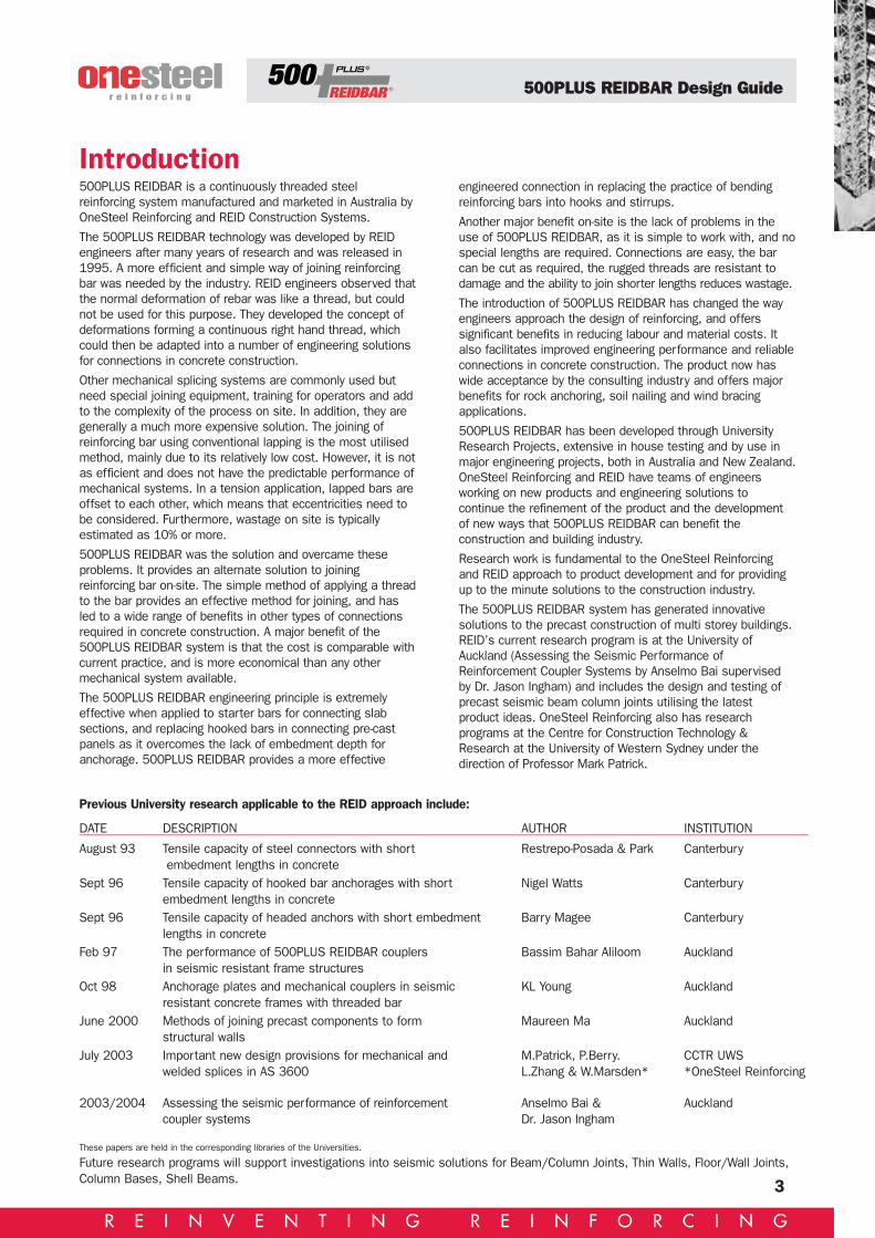
ComponentsREIDBAR Coupler Code Overall Hex Size Body Thread Weight
Length A/F A/C OD Depthmm mm mm mm mm kg
RB12C 90 25 29 22 43 0.23
RBA16C 102 30 34 30 47 0.31
RBA20C 129 37 43 35 61 0.50
RB25C 162 45 52 43 78 1.16
RB32C 210 57 66 55 102 2.30
Also available galvanized
REIDBAR NutsCode NUT Code Hex size may vary
Bar Yield depending on x 1.15 manufacturerLength mm Hex Size mm
RB12N* 40 25
RBA16N 35 0
RBA20N 45 36
RB25N 50 46
RB32N 65 50
RBA nuts are identified by a “V” groove machined into the hexagonat the half length or by stamping RBA—on the end face.* RB12N achieves maximum ultimate strength of bar
Also available galvanized

500PLUS REIDBAR Design Guide
11
ComponentsREIDBAR Foot Plate/Flange Nut Code Overall Hexagon Size Body Foot Weight
Length A/F Overall Dia. Overall Dia. kgmm mm mm mm
RB12FP 40 - 22 38 0.13
RBA16FP 51 30 30 50 0.24
RBA20FP 66 37 35 64 0.38
RB25FP 70 46 80 80 0.61
RB32FP 95 57 101 101 1.26
Also available galvanized
REIDBAR Threaded InsertCode Overall Body Foot Threaded Weight
Length Overall Dia. Overall Dia. Depth kgmm mm mm mm
RB12TI 100 22 38 43 0.23
RBA16TI 118 30 50 47 0.47
RBA20TI 148 35 64 61 0.72
RB25TI 191 43 80 78 1.27
Note 1: RB12TI, 16TI are also available hot forged with tri head RHINO FOOT. Stamped NZ on underside ofhead.
2: RBA--TI if cast are identified with a hexagon shape at the foot end of the body.: 3: RBA16TI is also available hot forged with tri head RHINO FOOT. Stamped A on underside of head.Also available galvanized
REIDBAR Threaded Insert Chair Code Comprises Minimum
Chair Adaptor Legs Panel Thickness mm
RB12TICH RBTIC RB12ADP NIL 125
RB16TICH RBTIC RB16ADP 3 150
RB20TICH RBTIC RB20ADP 3 175
Note 1: The chair will take all threaded inserts from RB12 to RB202: The chair can be used in 125mm to 200mm panel thicknesses
R E I N V E N T I N G R E I N F O R C I N G

500PLUS REIDBAR Design Guide
12
R E I N V E N T I N G R E I N F O R C I N G
REIDBAR Grout SleeveCode Overall Thread Body Body Nom Bar Embedment Weight
Length Depth ID OD Grout Vol Min Max mm mm mm mm ml mm mm kg
RB12GS 200 45 48-36 58-46 200 110 150 1.1
RBA16GS 240 47 32 50 200 140 190 1.4
RBA20GS 290 61 40 60 350 174 224 2.3
RB25GS 360 78 48 70 550 234 274 3.7
RB32GS 385 109 55 75 750 328 368 6.2
Note 1: RB32GS new design (485mm length) will be available during 2004
Components
Code Thread Thread Rubber Pluglength diameter OD
RB16GSSET 80 M8 32 also fits RBA16GS and RB32C
RB20GSSET 80 M8 40 also fits RBA20GS
RB25GSSET 80 M8 48
RB32GSSET 80 M8 55
Code Dimensions Weightkg
BPLATE20100 100 x 100 x 6.3 x 14 high 0.50
RB20SW 50 OD x 24 ID x 18 thick 0.15
BPLATE32150 150 x 150 x 10 x 24 high 1.70
RB32SW 70 OD x 37 ID x24 thick 0.31
REIDBAR Domed Base Plates & Spherical Washers
CONTINUING DEVELOPMENT MAY ALTER PRODUCT DIMENSIONS. CHECK WITH REIDIF CRITICAL TO YOUR APPLICATION.Commonly used accessories are available. These include Plastic Nail Plates for RB12,RB16, RB20 and RB25; and Bearer Plates.
Bar embedment depth
Also availablegalvanized
REIDBAR Grout Sleeve Setting Hardware

500PLUS REIDBAR Design Guide
13
Minimum embedment depths for threaded inserts & footplates in 25MPa and 30MPa concrete
Anchoring in Concrete
TABLE 2
Code Grade L1 Char L2 Char ThreadedDepth to develop Min Depth to develop Max Insert
Min Yield Yield Char Max Ult Ult LengthStrength Strength Strength tren plusmm kN mm kN 8mm*
25MPa 30MPa 25MPa 30MPa
RB12 500N 82 78 56.5 97 92 79 108
RB16 500N 110 103 100.6 130 122 140.8 126
RB20 500N 137 129 157.0 162 153 219.9 156
RB25 500N 171 161 245.5 203 191 343.7 199
RB32 500N 219 206 402.0 260 244 562.9 -
Note 1: The adoption of embedment depth L2 will ensure that the failure mechanism will be ductile rather than by brittle shear cone pullout.
Note 2: Embedment depth is calculated using the formulas developed by Haeussler. The general form is given as P = 0.972 x L2 x B2/3
where: P = pullout capacity of shear cone in NewtonsL = effective embedment depth in mmB = concrete compressive strength in MPa
(Test results have shown that pull out calculated with Haeussler will be about 15% conservative) (P.T. 2001)
Depth, edge and centre distanceeffectsThe design strength of concrete anchoring systems isdependent on many factors.
The five most critical are:
1. The compressive strength of the concrete.
2. The depth of embedment of the anchor foot.REIDBAR threaded inserts and footplates will develop thefull ultimate breaking strength of 500PLUS REIDBAR whenplaced at the embedment depth L2 shown in table 2. Atshallower depths the full breaking strength may not bereached and designers should apply the followingreduction factors to ascertain they have sufficient designstrength.
Reduction factors for reduced depths. To be applied to yieldand ultimate strength loads in table 2.
3. The shape of the anchor foot.REIDBAR threaded inserts and footplates provide a fullyeffective anchorage unlike a hooked bar with the sameembedment depth.
4. The proximity to other anchors.REIDBAR threaded inserts and footplates will develop thefull load capacity of the 500PLUS REIDBAR when placedat centres 6 times the minimum embedment L2 shown intable 2.
At closer spacing the full breaking strength of the bar may notbe reached.For example RB12 bars screwed into RB12TI (threadedinserts) at 300 centres in 25MPa concrete will still developthe characteristic yield strength (500MPa) of the bar but are
unlikely to develop the full breaking strength of the bar beforeconcrete rupture.(Bent bars at these centres and embedment depths can beexpected to provide significantly less capacity).Reduction factors for reduced bar centres to be applied toyield and ultimate strength loads in table 2.
This table applies to a single row of starters. If another row isrequired within 6L from this row, refer application toOneSteel. Correctly designed headed anchorages will alwaysoutperform hooked bars with the same effective depth.Reduction factors given will also apply to hooked bars.
5. Proximity to edges.REIDBAR threaded inserts and footplates will develop the fullload capacity of 500PLUS REIDBAR when placed at least 3times the minimum embedment (L2) from the edge of aconcrete component.Closer distances to edges will lead to the following reductionsin tensile capacity.Reduction factor for reduced edge distances. To be appliedto yield and ultimate strength loads in table 2.
FOR COMBINATION OF FACTORS SIMPLY MULTIPLYTOGETHER.
Depth 1L 0.9L 0.8L 0.7L 0.6L
Tensile reduction factor 1.0 0.80 0.65 0.50 0.35
Bar centres 6L 4L 2L 1L 0.5L
Tensile reduction factor 1.0 0.87 0.50 0.26 0.13
Distance to edge 3L 2L 1L 0.5L
Tensile reduction factor 1.0 0.87 0.50 0.26
* Screw in plastic nail plates recess the insert by 8mm
R E I N V E N T I N G R E I N F O R C I N G

500PLUS REIDBAR Design Guide
R E I N V E N T I N G R E I N F O R C I N G
HD PVC tube aroundbar if wanting to screwin verticals after layingblocks
RB12TI at 600 centres RB12NP tosupportthreaded insert(until concretecures)
Cavity filled with17.5 block mix
Typically RB12 at600 centres
Timberbottomplate
RB12N and washer
DPC
Header block
DPC2~RB12 bars
RB12 at 600 centres (typical)
Cavity filled with 17.5 block mix
RB12NP to support threadedinsert (until concrete cures)
RB12TI at 600 centres
RB____C RB____
Current pourPrevious pour
RB12N and washer
Typical Construction DetailsDomestic basement wallDETAIL 3
Common retainingwall footingDETAIL 4
Strip foundation inunstable groundDETAIL 5
14
500PLUS REIDBAR Design Guide
15
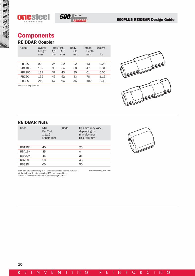
Typical Construction Details
RB___C
Fill cups withrecommended groutbefore placing
RB___GS
Fillet Strip RB___C RB___
NP___RBScrew through mouldinto nail plate
Steelpanelmould
Fillet StripTimber Liner
RB___TIPlasticplug
NP___RBScrew or nail to timber liner ordirectly to mould
Steelpanelmould
Anchorage for column startersDETAIL 6
Threaded insert to edgeof precast panelDETAIL 7
Coupling to edge ofprecast panelDETAIL 8
Pre-cast column elementsDETAIL 6A
Always ensure that the coupler is firmly screwed onto nail plate.Nail plates WILL NOT support foot traffic. Support the bar close to the coupler.
These columnstarters aretemporarilyterminated at floorlevel to provide a flatobstruction-free floorfor use as aprecasting bed.
Thread in prior to joining on site. (Alternatively, thevertical bars could extendthrough the column baseand into the grout sleeve,provided this does notcause handlingproblems.)
R E I N V E N T I N G R E I N F O R C I N G

500PLUS REIDBAR Design Guide
R E I N V E N T I N G R E I N F O R C I N G
Typical Construction DetailsGrout sleeve to edge ofprecast panelDETAIL 9
Footplate set deep in edgeof precast panel DETAIL 11
RB___
RB___GSRigid PVC tube
RB___GSSET
STEEL PANEL MOULD
Steel panelmould
RB___
RB___GS Plastic plug (Grout tubes optional)
Steel panel mould
Fillet strip
RB___WN
RB___
RB___FPRigid PVC tube
Used where anchorage depth varies fromstandard Threaded Insert Length.
RB___GSSET
Grout sleeve to edge of rebated precast panelDETAIL 10
16

500PLUS REIDBAR Design Guide
R E I N V E N T I N G R E I N F O R C I N G
Seismic Floor/Wall Connection detail DETAIL 14
Typical Construction Details
RB___
RB___Screw start bars into couplingbefore lowering into position(Alternatively, vertical bars couldextend into the grout sleeve,provided this does not causehandling problems)
RB___GS
RB___
Flood joint with approvedwith grout
RB___C
RB___
Flood joint withapproved grout
RB___
Grout tubes
RB12 500PLUS REIDBAR@ 600 Ctrs.Anchored with RB12 Footplate
Attachment Hangers2 per section SPS 20 Superplus Bolt2FA170 Swiftlift Stud
Probable movementwhen floor pulled awayfrom angle support
DRILL Ø22
25
68
190
6mm FILLET
6mmFILLETRIGHTROUND
SECTION BB SECTION AA
C
PART SECTION CC
NOTE: THIS DETAIL COULD ALSO BE USED WITH FLAT SLABS AND TEE SECTIONS
MESH OMITTED FROM THIS VIEW
C
B
B
A
A
50 x 50 x 6 washer
306
INSIDE FACE
Horizontal structural joint fortwo precast panelsDETAIL 12
Horizontal structural joint forrebated precast panelsDETAIL 13
17
R E I N V E N T I N G R E I N F O R C I N G

500PLUS REIDBAR Design Guide
R E I N V E N T I N G R E I N F O R C I N G
Typical Shear Wall ConnectionDETAIL 15
Typical Construction Details
Tests on the arrangement detailed haveshown that REID headed studs willtransfer the shear stress across a jointbetter than conventional hairpins of anequivalent steel area.Small hairpins at the upper and lowerends of the joint add to theconfinement and help to control localdeformation at ultimate loads.
Panel 2INFILL POUR
Panel 1
RB12HeadedStud orFootplate
R6 Hairpins attop and bottom
of joint
RB12Coupler
RB12 Barsalongside
heads of studs RB16 Nail Plate
RBA16TI IN 150 PANEL
RB12 Nail Plate
RB12TI IN 125 PANEL
Deformed bar Flood joint with approved grout RB___GS RB___
Support sleeve, seal inner end with a stiff high-strengthmortar and fill with approved grout
RB20TI IN 250 PANEL Australia only
Threaded Insert to Faceof Precast PanelDETAIL 16
18
Joining 500PLUS REIDBAR to Deformed Bar DETAIL 17

500PLUS REIDBAR Design Guide
R E I N V E N T I N G R E I N F O R C I N G
500PLUS REIDBAR starter bar systems have been developedto provide full strength and positive connections betweenprecast concrete panels, floor slabs and insitu suspendedfloors. The system comprises 500PLUS REIDBAR ThreadedInserts, 500PLUS REIDBAR Starter Bars, specially designedPlacement Chairs, Nailing Plates and Antenna Caps.
The versatility of the system allows the contractor to set upthe Threaded Inserts prior to the panel being poured or to‘puddle them in’ before the panel is floated off. Whatever themethod used, 500PLUS REIDBAR starter bar systems offerstrength, stability, price effectiveness and ease of operationthat you just don’t get with standard NBar starter bars.
Features:• Available in RB12, RBA16 and RBA20 diameters – off theshelf.
• Thread diameter is true to size – not a N20 bar with athread turned down to 16mm.
• Coarse thread on the bar resists damage and minimizesforeign materials blocking the threads of the cast-inThreaded Insert.
• Coarse thread results in speed of application whenscrewing the Insert and Starter together.
• System components are purpose designed and offerspeed of set up and installation either in the Precast yardor on site.
• Non standard lengths are easily catered for as starterbars are cut from standard 6 or 12 metre lengths ofThreaded Reinforcing Bar.
Starter Bar Systems
Comparison Table - 500PLUS REIDBAR Starter Bars vs N-bar Starter BarsTABLE 3
STRESSED Limit stateBAR SIZE GRADE METRIC AREA fsy strength
MPa THREAD mm2 kN ø fsykN
N12 500N M10 58 21.8 17.4
RB12 500N RB12 113.1 56.5 45.2
N16 500N M12 84.3 31.6 25.3
RBA16 500N RB16 201 100.5 80.4
N20 500N M16 157 58.9 47.1
RBA20 500N RB20 314 157.1 125.7
N24 500N M20 245 91.9 73.5
RB25 500N RB25 491 245.5 196.4
System Components
TISK Big Foot Insert
Nailing Plates Antenna Caps
19

500PLUS REIDBAR Design Guide
R E I N V E N T I N G R E I N F O R C I N G
Ultimate Tensile Load Capacity Table(A) CANTILEVERED DETAILFor 500PLUS REIDBAR starter bars with 500PLUSREIDBAR Threaded Inserts Big Foot FerrulesTABLE 5
Threaded Embed. Edge CentresInsert depth distance distance 25MPa 30MPaSize (L) (E) (C) ULTIMATE TENSILE CAPACITY (KN)
Characteristic min. ultimate strength of bar = 61 kN
RB12TISK 108 75 150 34.9 39.4
RB12TISK 108 100 200 45.7 51.6
RB12TISK 108 125 250 55.8 61.0
RB12TISK 108 150 300 61.0 61.0
RB12TISK 108 175 350 61.0 61.0
RB12TISK 108 200 400 61.0 61.0
RB12TISK 108 225 450 61.0 61.0
RB12TISK 108 250 500 61.0 61.0
RB12TISK 108 275 550 61.0 61.0
RB12TISK 108 300 600 61.0 61.0
RB12TISK 108 325 650 61.0 61.0
Characteristic min. ultimate strength of bar = 108.5 kN
RBA16TISK 126 150 300 77.9 88.0
RBA16TISK 126 175 350 88.7 100.2
RBA16TISK 126 200 400 98.5 108.5
RBA16TISK 126 225 450 107.3 108.5
RBA16TISK 126 250 500 108.5 108.5
RBA16TISK 126 275 550 108.5 108.5
RBA16TISK 126 300 600 108.5 108.5
RBA16TISK 126 325 650 108.5 108.5
RBA16TISK 126 350 700 108.5 108.5
RBA16TISK 126 375 750 108.5 108.5
Characteristic min. ultimate strength of bar = 169.6 kN
RBA20TI 153 150 300 96.6 109.1
RBA20TI 153 175 350 110.9 125.3
RBA20TI 153 200 400 124.3 140.5
RBA20TI 153 225 450 136.9 154.7
RBA20TI 153 250 500 148.5 167.7
RBA20TI 153 275 550 158.9 169.6
RBA20TI 153 300 600 168.3 169.6
RBA20TI 153 325 650 169.6 169.6
RBA20TI 153 350 700 169.6 169.6
RBA20TI 153 375 750 169.6 169.6
RBA20TI 153 400 800 169.6 169.6
RBA20TI 153 425 850 169.6 169.6
RBA20TI 153 450 900 169.6 169.6
Threaded Embed. Edge CentresInsert depth distance distance 15MPa 20MPa 25MPa 30MPa 32MPaSize (L) (E) (C) ULTIMATE TENSILE CAPACITY (KN)
Characteristic min. ultimate strength of bar = 61 kN
RB12TISK 108 75 150 14.8 17.9 20.8 23.5 24.5
RB12TISK 108 100 200 22.1 26.8 31.2 35.2 36.8
RB12TISK 108 125 250 29.9 36.3 42.1 47.6 49.7
RB12TISK 108 150 300 37.7 45.7 53.1 60.0 61.0
RB12TISK 108 175 350 45.2 54.8 61.0 61.0 61.0
RB12TISK 108 200 400 52.1 61.0 61.0 61.0 61.0
RB12TISK 108 225 450 58.1 61.0 61.0 61.0 61.0
RB12TISK 108 250 500 61.0 61.0 61.0 61.0 61.0
RB12TISK 108 275 550 61.0 61.0 61.0 61.0 61.0
RB12TISK 108 300 600 61.0 61.0 61.0 61.0 61.0
RB12TISK 108 325 650 61.0 61.0 61.0 61.0 61.0
Characteristic min. ultimate strength of bar = 108.5 kN
RBA16TISK 126 150 300 42.2 51.2 59.5 67.2 70.2
RBA16TISK 126 175 350 51.3 62.3 72.3 81.7 85.3
RBA16TISK 126 200 400 60.1 72.9 84.7 95.7 99.9
RBA16TISK 126 225 450 68.4 82.9 96.3 108.5 108.5
RBA16TISK 126 250 500 75.8 91.9 106.7 108.5 108.5
RBA16TISK 126 275 550 82.2 99.7 108.5 108.5 108.5
RBA16TISK 126 300 600 87.4 106.0 108.5 108.5 108.5
RBA16TISK 126 325 650 91.3 108.5 108.5 108.5 108.5
RBA16TISK 126 350 700 93.8 108.5 108.5 108.5 108.5
RBA16TISK 126 375 750 94.7 108.5 108.5 108.5 108.5
Characteristic min. ultimate strength of bar = 169.6 kN
RBA20TI 153 150 300 48.1 58.3 67.7 76.5 79.9
RBA20TI 153 175 350 59.1 71.7 83.2 94.1 98.2
RBA20TI 153 200 400 70.2 85.1 98.9 111.7 116.6
RBA20TI 153 225 450 81.1 98.4 114.2 129.1 134.8
RBA20TI 153 250 500 91.6 111.1 129.0 145.8 152.2
RBA20TI 153 275 550 101.5 123.0 142.9 161.5 168.6
RBA20TI 153 300 600 110.5 134.0 155.6 169.6 169.6
RBA20TI 153 325 650 118.6 143.8 167.0 169.6 169.6
RBA20TI 153 350 700 125.5 152.2 169.6 169.6 169.6
RBA20TI 153 375 750 131.2 159.0 169.6 169.6 169.6
RBA20TI 153 400 800 135.4 164.2 169.6 169.6 169.6
RBA20TI 153 425 850 138.2 167.6 169.6 169.6 169.6
RBA20TI 153 450 900 139.6 169.6 169.6 169.6 169.6
If the bar is being used to provide a moment connection and the compressive reaction is applied within the shear cone boundary, it is likely that the anchorage capacity will be improved.
Ultimate Tensile Load Capacity Table(B) SUSPENDED FLOORFor 500PLUS REIDBAR starter bars with 500PLUSREIDBAR Threaded Inserts Big Foot FerrulesTABLE 6
Starter Bar Systems
(A) CANTILEVERED DETAILFOR 500PLUS REIDBARSTARTER BARS
20
(B) SUSPENDED FLOORS FOR500PLUS REIDBAR STARTERBARS

500PLUS REIDBAR Design Guide
R E I N V E N T I N G R E I N F O R C I N G
Frequently Asked QuestionsQ How far into the coupler must the bar be
threaded?A Tests show that to achieve the ultimate strength of the
connection the thread engagement MUST BE AT LEAST80% of the maximum available in the fitting. Correct barinsertion is critical to the performance of the 500PLUSREIDBAR system. We recommend that good practiceREQUIRES the user to mark the bar at half couplerlength back from the inserted end so that a visual checkis available.
Q Is tightening torque critical in the performance of500PLUS REIDBAR components?
A Provided the bar is screwed tightly against the centrestop, or fully through the component, whichever isappropriate, the full breaking strength of the bar will bedeveloped. Does not apply to nuts as shown on page10. We recommend using a wrench with a minimumlength of 300mm to ensure the bar is fully engaged.
Q How much slip occurs in the thread of a coupleras it is loaded?
A Recent tests have shown that up to 0.5mm of slip canoccur in each end of the coupler at loads approachingyield. If this is an issue with crack widths at serviceabilitylimit state then couplers should be filled with REIDSwiftchem polyester resin at assembly. Tests with epoxyfilled RB16 couplers show slips around 0.2mm per endat 75% of bar yield. The effect of slip can be furtherreduced by staggering alternate couplers. An appropriatestagger distance would be the development length of thebar size being used. It should be noted however that inmost cases the 500PLUS REIDBAR fittings will be usedat construction joints which typically have crack widthswell above the coupler slip value.
Q How much slip occurs in the thread of a coupler ifnuts are fitted?
A Theory suggests that if we can induce a tension preloadinto a coupler which exceeds the required bar tensionthen no additional slip will be seen across the coupleruntil that pretension load is exceeded. Tests carried outat Auckland University in 2002 have shown that if thecorrect preload is applied using nuts tightened againstthe coupler ends, the coupled bar assembly will be stifferthan an unspliced bar at the same gauge length. Couplerslips measured across this gauge length are typicallyaround 0.1mm. Refer critical applications to REID.
Q What is the best way of cutting 500PLUSREIDBAR before joining?
A With an abrasive cutoff wheel or cutoff saw. Sheared orcropped ends usually present problems. Poorlymaintained equipment will leave a misshaped corediameter and excessive burr on the bar end making nutsand couplers hard to thread on. RB 12 can normally becut with a bolt cutter. Oxy acetylene cutting is a simpleand quick way of cutting large bars on site. Note:Starting the cut on the ridge of a 500PLUS REIDBARthread minimises heat input.
Q What end treatment is required before coupling?A If difficulty is encountered because of burring or
distortion of the end during cutting or shearing then alight dressing with an angle grinder to remove thedamage is all that is required.
Q What type of nuts should I use and when?A1 For most splicing and anchoring applications the primary
fittings (couplers, foot plates, inserts, grout sleeves)may be used without additional nuts. Tests havedemonstrated code compliance to meet the seismicrequirement of clause 7. 5. 1. 3 of NZS 3101:1995when the components are tested whilst embedded inconcrete. In order to satisfy the code, the spliced barmust not deflect more than 1.1 times the deflection foran equivalent gauge length of plain bar. StandardREIDBAR splices without nuts met the requirement. (Adiagram of the test rig is shown on page 9). Nuts arenot required with Grout Sleeves.
A2 Flange nuts (modified foot plates) and torque nuts.These are used for all designs where the nut is requiredto develop the full breaking strength of the bar e.g.terminations for rock bolts, ground anchors, hold-downbolts, tensioning applications etc. Torque nuts andflange nuts develop higher strengths to meet therequirements of NZ3101 for mechanical connectors.
A3 In critical applications (in plastic hinge zones) additionalnuts may be required to fully transfer load reversal underseismic events. In this case double nuts or torque nutsare used. Refer to questions/answers opposite on slipand pre load.
21(Refer Anselmo Bai/Dr. Jason Ingham test results page 3)

500PLUS Design Guide
22
R E I N V E N T I N G R E I N F O R C I N G
Q What testing has been done for 500PLUSREIDBAR?
A During the development of 500PLUS REIDBAR, extensivetests were conducted by REID to ensure compliance withall applicable codes, including the special seismicrequirements of New Zealand Reinforcement andStructural Design Standards. Tests have included cyclictension load tests, pullout tests to check embedmentanchorage, slip tests,etc. OneSteel Reinforcing and REIDcontinually monitor the system’s quality using accreditedtesting laboratories in an ongoing program of testing anddevelopment. Research continues to be undertaken.
Q Bending and rebendingA 500PLUS REIDBARs are highly ductile. 500PLUS
REIDBAR can be cold bent and rebent around theminimum former diameters specified inAS/NZS4671:2001 and NZS3402 without fracture.
The 500PLUS REIDBAR system can solve structuralconnection problems often encountered in thin sectionsor joints with thin panels. Refer detail 1a and 2 on page 8.
Q I want to bend large diameter bars. Can I heat500PLUS REIDBAR to assist in bending?
A1 RB12 is a micro alloyed bar and there will be minimalchange to the mechanical properties if the bar is allowedto cool in still air.
A2 RB16-32 are TEMPCORE bars and should not be heatedif the original mechanical properties are required.
Q Can I straighten an accidentally bent 500PLUSREIDBAR on site?
A1 RB12MA; YES, but with caution, especially if the bendradius is very small. Avoid using impact. It is better toheat the bar to a cherry red and rebend slowly. Allow tocool in still air.
A2 RB16-32TC; May be straightened cold provided due careis exercised and an appropriate method used tostraighten the bar. The bar should be closely examinedafter straightening to ensure that there are no visiblecracks in the bar at the rebend position.
Q Can I weld cast 500PLUS REIDBAR fittings?A Although Cast S.G. Iron fittings are weldable using
specialised techniques we do not recommend thepractice because the process will degrade the strengthand ductility of the fitting and therefore it will not meetits performance characteristics as stated in this manual.Hot forged nuts can be welded. Nuts manufactured fromfree machining steels can also be welded but cautionneeds to be exercised if load capacity is critical. ContactREID for further information regarding welding.
Q Can 500PLUS REIDBAR be hot dip galvanisedwithout loss of properties?
A1 RB12 is a micro alloyed bar with stable properties andmay be bent without the risk of cracking aftergalvanising. All bending/rebending should use thelargest possible bend radius. (Note: heavy coatings ofgalvanising on 500PLUS REIDBAR may preventcomponents being fitted. Refer all galvanisingapplications to REID local distributor.
A2 RB16-32TC will not generally be affected by hot dipgalvanising. However, it is not recommended that barsbent prior to galvanising be rebent. If this must beperformed careful checking for cracking should becarried out. All bending / rebending should use thelargest possible bend radius.Note: A galvanising thickness of 100 microns is allowedin the design of galvanised fittings.
Gaugelength(345mm)
DETAIL 18
Cyclic loading + 0.95fy -0.95fyDeflections measured at lessthan 1.1 times the gauge lengthof an equivalent length of bar.
Diagram of test arrangement
125 APIlinepipe x250 long
Frequently Asked Questions

500PLUS Design Guide
23
R E I N V E N T I N G R E I N F O R C I N G
Q How do I connect one precast concrete elementto another using 500PLUS REIDBAR?
A Easily with the 500PLUS REIDBAR grout sleeve. A500PLUS REIDBAR grout sleeve is cast into the top ofthe lower element and a coupler into the bottom of theupper element. This eliminates the need for any starterbars protruding from the precast elements and which
are liable to damage and to be bent which makeserection difficult. Immediately prior to final placing astarter bar of the correct length is screwed into thecoupler and non-shrink grout is poured into the groutsleeve cup. The units are then brought together into thefinal position, levelled and propped.Note: this pre-grout method avoids the necessity forcasting-in grout tubes and the need for a separategrouting operation. (See typical detail 6A and 12).NOTE: TO EFFECTIVELY ANCHOR A GROUT SLEEVE ITREQUIRES AT LEAST A LAP LENGTH OF BARPROTRUDING SCREWED INTO THE THREADED END
Q What grout can I use in 500PLUS REIDBAR groutsleeves?
A Most general purpose grouts with a 28-day compressivestrength exceeding 65Mpa when used in a flowableconsistency. REID grout sleeves have been tested withFosroc Conbextra GP, Sika Grout 212, MBT 830.
Q What are the minimum cover requirements for500PLUS REIDBAR and components.
A1 Code requirements e.g. AS3600 requirements forreinforcement must be observed.
A2 Components. The two main factors to be considered areFire and Corrosion. Sufficient protection for thecomponents should be specified by the designeraccording to the fire, corrosion and other serviceabilityrequirements of the application, taking into considerationthe relevant codes and the following notes which providea guide for designers.
A3 Fire. The temperature of the steel reinforcing is affectedby the cover of concrete over the full extent of theembedded bar. The temperature is averaged over thesteel by conduction along its length which acts to quicklydissipate any localised temperature variations. A minorreduction in the cover in a very localised area (e.g. at acoupler) would therefore not lead to any significantincrease in steel temperature and no increasedreduction in strength.
A4 Corrosion.(1) 12mm (RB12 series) 500PLUS REIDBARcomponents and selected other fittings are made fromnormal steels and require the same cover as the baritself unless galvanised or otherwise protected.
(2) 500PLUS REIDBAR components in sizes larger thanRB12 are generally manufactured from specially alloyed,high strength, ductile iron. Ductile iron corrodes at about30% of the rate of reinforcing steels and the products ofthe corrosion are not expansive. As such ductile irondoes not lead to the spalling and flaking problemscommonly associated with the corrosion of steels inconcrete. Cover to Ductile Iron components can bereduced because of this good corrosion resistance. Wewould suggest that cover be maintained to at least 50%of code requirements for reinforcing steel. The exceptionto the better corrosion resistance of ductile iron is seawater and in that case it is preferable to use the samecover limitations as the bar
TABLE 7
Code Grade Thread Stressed YieldType Area sq Strength
mm (1) kN
RB12 500N (2) M10 58 21
RB12 500N RB12 113 56
RBA16 500N (2) M12 84 31
RB16 500N RB16 201 100
RBA20 500N (2) M16 157 58
RB20 500N RB20 314 157
RB25 500N (2) M24 353 130
RB25 500N RB25 491 245
RB32 500N (2) M30 561 205
RB32 500N RB32 804 402
1. Stressed area from AS 4291 Pt 12. 500N values taken from OneSteel 500PLUS Brochure
Frequently Asked QuestionsQ Does 500PLUS REIDBAR lose mechanical strength
when machined?A1 RB12, being a micro alloyed bar, will have homogeneous
mechanical strengths across the full cross section.
A2 RB16-32 are TEMPCORE bars and will not havehomogeneous mechanical strengths across the full crosssection.
Q How does 500PLUS REIDBAR starter bar comparewith a metric threaded starter bar?There are four issues here:
A1 The minimum core diameter of reinforcing bars do notallow the same diameter metric thread to be cut to a fullprofile.
A2 The thread cutting process will induce a notch effect atthe distal end of the thread and further reduce the barstrength, e.g., tests with M32 thread on a YD32 bar hadan ultimate capacity of 327kN compared with 504kNultimate for the unthreaded bar. RB32 bar maximumultimate 562kN.
A3 500PLUS REIDBAR threaded inserts have an effectivedepth allowing ductile failure at full bar strength. Metricthreaded inserts tend to be shorter.
A4 See TEMPCORE machining notes above.

500PLUS Design Guide
24
R E I N V E N T I N G R E I N F O R C I N G
Q Can I use the 500PLUS REIDBAR system attemperatures below freezing?
A All low temperature applications should be consideredcarefully, especially where impact loads are alsopresent. AS/NZS 4671:2001 has no impact testrequirement. Recent tests have shown values of Charpyimpact resistance for RB32 at -15°C at around 17joules. Grade 500/7 SG Iron is not recommended forservice at temperatures below freezing if impact loadsare present.
Q Can I use SG Iron REIDBAR components for lifting?
A No. In casting processes there is always a potential forcasting defects. While vigilant QA procedures are inplace, 100% inspection is not possible.
Q Is the performance of threaded inserts affectedby cracks?
A Yes. We recommend that the ultimate capacity ofthreaded inserts be reduced by 25% for crack widths of0.4mm and 30 - 40% for crack widths of 0.8mm.DO NOT PLACE THREADED INSERTS IN THE LIKELYBURSTING ZONE OF COVER CONCRETE TO TENSIONSTEEL.
Q What is the relationship between torque appliedto the nut and tension induced in the bar?
A The relationship of Torque versus tension in 500PLUSREIDBAR systems is reasonably linear up to about 25%of the bar yield strength. After this load, increasingtorque may not translate into increasing tension. Forreliable tension loads above 25% of bar yield the barmust be stressed by hydraulic or mechanical jacking.
Frequently Asked Questions
INCREASING TORQUE ABOVE THESE VALUES MAY NOT RELATE TO INCREASED TENSION

500PLUS Design Guide
25
R E I N V E N T I N G R E I N F O R C I N G
SOIL & ROCK ANCHORINGFeatures and benefits• 500PLUS REIDBAR has closely defined mechanicalproperties which provide consistent performance underlong term anchor loading.
• Unlike strand tendons the solid anchors have noconstructional losses.
• Supplied in the hot rolled condition which is effectivelystress-free.
• The high ductility and smooth, relatively flat rate of strainhardening ensures a high margin of safety againsttensile/shear overload in the case of transversemovements in the rock or soil.
• Resists dynamic loads (e.g. traffic wheel loads).
• Preloading to the full working load ensures that the loadtransmitted to the anchorage medium (rock or soil) isconstant i.e. live loads are not transmitted to theanchorage medium.
• A range of chemical and expansion anchors enhance theversatility of the system.
• Rugged thread is resistant to damage.
• May be tensioned, released and re-tensioned with ease
• Simplicity in applying the prestress with jacks, torquewrenches or air operated tools
• Recoverable anchors may be removed to simplify laterexcavations
• The rigidity of the anchors makes them easy to installespecially in overhead applications.
• High shear bond as deformations are designed for shearinterlock with concrete or resin.
• Transmits the anchor forces efficiently to the grout bodywithout additional fittings.
• Standard stock lengths may be stored and cut to suit theapplication.
• Offcut bars may be used for all standard concretereinforcement applications in the construction site whilstsmall pieces are ideal for formwork, starter bars orhangers in underground works.
• Can be cut and spliced at any point along its length
• Can be welded

500PLUS Design Guide
26
R E I N V E N T I N G R E I N F O R C I N G
Rock anchorsRock anchors have traditionally been grouted with cementgrouts. The ultimate strength of an anchor in soundcompetent rock is dependent on many factors. Among themore important of these is the unit bond stress capacity ofthe rock/grout interface, the unit bond stress capacity of thebar/grout interface, the length of the anchor and theconsequences of failure.
The capacity of the cement grout to both bond to and protectthe bar as well as to bond with the substrate is largelydependent on the water cement ratio.
“The bond and shear characteristics of a cement grout arealso determined largely by the water cement ratio. The idealwater cement ratio lies in the range 0.35 to 0.4 (Hyett et al.,1992). Cement grouts above 0.4 will cure with excessivemicro porosity and grouts below 0.35 could be difficult topump and may be susceptible to void forming and incompletewetting of the strata.”
As a practical guide a grout with a cement water ratio 0.35 isdescribed as ‘sticks readily to and hangs from the hand whenupturned’ and a ‘0.4 grout readily sticks to the hand but canbe shaken free’.
Rock/grout interfaceThe rock/grout interface is subject to so many vagaries thatthe choice of a suitable bond stress valueis often difficult.
As a general guide the ultimate bond stress for competentrock can be taken as 10% of uniaxial compressive stress(where the uniaxial compressive strength is above 20MPaand the bond stress is limited to a max of 4.2MPa) (afterLittlejohn and Bruce 1977).
Test bores will give a guide to the initial selection but on siteproof load tests are always advisable. The ability of rock toadequately confine the grout column reduces as the anchorlength decreases below 1 metre (after Morris and Sharp1973). We suggest that the bond strength of the first 600mmof the hole depth be ignored unless massive unfractured rockis at the surface.
Anchorage with Cement Grout
Specifications & Working LoadsTABLE 9Mechanical properties and working loads for 500PLUS REIDBAR.
Code Grade Char Char Char Char MaxYield Min Min Min Tensile Stress Yield Ult Shear Working
Strength Strength .62 min Ult LoadMPa kN kN kN kN
RB12 500N 500 56.5 61 37.8 39
RBA16 500N 500 100.6 108.5 67.3 70
RBA20 500N 500 157.0 169.6 105.2 109
RB25 500N 500 245.5 265.1 164.4 171
RB32 500N 500 402.0 434.2 269.2 281

500PLUS Design Guide
27
R E I N V E N T I N G R E I N F O R C I N G
Anchorage with Cement GroutTABLE 10A guide to the ultimate strength of 500PLUS REIDBAR in cement grouted holes (typically 20MPa min) (bond stresses afterLittlejohn and Bruce 1977, Table 25 BS 8081 1989)
Material Ultimate ULTIMATE STRENGTH IN KN PER METRE FOR NOMINATED HOLE DIABond N/mm2 65mm 75mm 90mm 100mm 150mm
Soft Shale 0.21 - 0.83 42 - 169 49 - 195 59 - 234 65 – 260 98 - 391
Sandstone 0.83 - 1.73 169 - 350 195 – 407 234 - 486 260 - 543 391 - 562
Slate & Hard Shale 0.86 - 1.38 175 - 281 202 - 325 243 - 390 270 - 433 405 - 562
Soft Limestone 1.0 - 1.52 204 - 310 235 - 358 282 - 429 314 - 477 471 - 562
Granite & Basalt 1.72 - 3.10 351 – 562 405 - 562 486 - 562 540 - 562 562 - 562
Concrete 1.38 - 2.76 281 - 562 325 - 562 390 - 562 433 - 562 562 – 562
NB: For working loads apply a factor of safety of at least 2.5 to these ultimate loads. The bond developed by added length of embedment may not be proportional to the additionallength. The load transfer mechanism between grout and fissured rock is much less certain and it is advisable to consolidate and seal the cracked rock by pregrouting beforeinstallation of the anchor.
Non-shrink groutsFor sites with limited or very restricted access, shrinkagecompensated, cement-based grout capsules are available.These capsules are supplied as a ready-to-use powderencapsulated in a water permeable skin. When required foruse the capsules are simply soaked in water for about 5mins which penetrates the skin and wets the powder, forminga plastic non-shrink grout. Capsules are 25mm diameter x320mm long.
Soil anchorsThe following tables (Tables 12 & 13) give guide values forthe load transfer capacity of various broadclassifications of non-cohesive and cohesive soils. A testanchor should be made to reliably determine the loadcapacity. The following information is provided for guidanceonly. A geotechnical engineer should be consulted todetermine the appropriate design requirements.
TABLE 11
Ultimate bond stress with rock are not less than the values inTable 5
Code Max Bar Min. Recomm. CapsulesOD Hole Diameter per Metre
RB12 14.2 25 3
RB16 18.4 25 2
RB20 22.5 28 2
RB25 28.6 35 3
RB32 35.9 42 4
REID product code “GROUTCAP”
TABLE 12
A guide to working bond strengths between non-cohesive soils and cement grout
Soil types Condition Bond strengthMPa
Sandy gravels Very dense 0.38
Dense 0.30
Medium dense 0.20
Medium coarse sands with gravel Very dense 0.25
Dense 0.20
Medium dense 0.17
Fine to medium sands Dense 0.19
Medium dense 0.11

500PLUS Design Guide
28
R E I N V E N T I N G R E I N F O R C I N G
Table 13A guide to working adhesive strengths between cohesive soils and cement grout
Clay Field test Unconfined Typical Working WorkingCondition Compressive undrained Strength Strength
Strength Shear Strength Adhesion Adhesion(qu) (Cu) Short term ong termkPa kPa kPa kPa
Very soft Exudes between fingers when squeezed in fist 10 5 1 2Soft Easily penetrated by thumb 18 9 2 4
Medium strength Difficult to penetrate with thumb 40 20 4 8
Firm Easily indented with thumb nail 75 37 7 14
Stiff Readily indented with thumb nail 150 75 15 30
Hard Difficult to indent with thumb nail 300 150 30 60
* Working strength short term based on 0.5Cu/2.5 as the drilling operation causes temporary remoulding of the clay at the edge of the bore hole.** Working strength long term based on Cu/2.5
Typical Grouted AnchorTo position bar centrally in drilled holes a Bar Centraliser isused
ALSO SUITABLE FOR USE EITHER HORIZONTALLY ORVERTICALLY.
RB20/16 CEN SHOWN.
THIS PRODUCT SUITS A NOMINAL HOLE DIAMETER OF100mm.
NOM. 1.5
METRES
NOM. 0.5
METRES
Grout
Grout tubetaped to bar

500PLUS Design Guide
29
R E I N V E N T I N G R E I N F O R C I N G
A more recent development for securing rock bolts, tie backsor rock dowels is to use resin to bond the 500PLUS REIDBARover part or all of the 500PLUS REIDBAR length. Very fastinstallation can be achieved using resin anchors.
Each bore hole must be cleaned out with air or water afterdrilling and before the resin cartridge is installed.Table 14 shows the correct cartridge to be used for each500PLUS REIDBAR size and bore hole diameter. Failure touse the correct diameters may result in inadequate mixing ofthe two part resin and reduced final bond strength.
Optimum performance of the 500PLUS REIDBAR anchor isachieved when the applied preload from final stressingexceeds the maximum applied working load of the anchor. Incertain applications pre-stress is not required and theanchors may be proof loaded to ensure integrity according tothe design requirement.
Stressing of 500PLUS REIDBAR is simple with either:1) a hollow bore hydraulic jack or2) a large torque wrench or air wrench. Refer Questions andAnswers, from page 21.
The anchorage length can be determined from the followingtable according to the calculated anchor load determinedfrom site conditions and design requirements.
Anchorage with Resins
TABLE 14Bond length in mm for resin anchors to achieve bar ultimate strength
Code Bore hole Resin 90 MPa 50 MPa 30 MPa 14 MPa 5 MPadiameter Cartridge Granite Limestone Concrete Sandstone Mudstonemm
RB12 18* 200 250 360 400 625
RB16 25 RS25G7330 225 300 480 550 850
RB20 27 RS25G7330 250 375 600 700 1120
RB25 32 RS32G7450 300 450 750 910 1500
RB32 40 RS36G7500 400 575 960 1175 1950
RS25G7330 = 320 x 25 dia. = 157cc
* Minimum of 18 or as close as possible. Anchor capacity will reduce as hole size increases.
TABLE 15Number of resin cartridges per bore hole to achieve Table 14 strengths
Code Bore hole Resin 90 MPa 50 MPa 14MPa 5MPadiameter Cartridge Granite Limestone Sandstone Mudstonemm
RB12 18* 1 1 2 3
RB16 25 RS25G7330 1 1 2 3
RB20 27 RS25G7330 1 1 2 3
RB25 32 RS32G7450 1 1 2 3
RB32 40 RS36G7500 1 1 2 3
Note:1. The above resin usage does not include a waste allowance for over-drilling. Site trials should be conducted to confirm resin requirements. 2. Due to the short shelf life resin anchors may not always be available ex stock.* Minimum of 18 or as close as possible. Anchor capacity will reduce as hole size increases.
500PLUS Design Guide
30
R E I N V E N T I N G R E I N F O R C I N G
Drill and clean holeDrill a hole with diameter in accordance with Table 14. Fordeep holes it may be necessary to drill a larger hole initiallyand reduce to the correct bore diameter in the deeper region.Remove all debris from drilled hole. Flush clean with oil-freecompressed air.
Insert Resin CartridgeInsert the required number of resin cartridges into the holeand carefully push them to the end. If an active anchorage isrequired, use the Duo-speed cartridge system which has afast setting resin at the leading end and slower setting resinat the tail end which sets after pre-stress has been applied.
Insert 500PLUS REIDBARSpin the 500PLUS REIDBAR anticlockwise for right handthreaded bar and clockwise for left hand threaded bar. Usean electric or air drill spinning at approximately 100 RPM.With the bar spinning, push the bar through the cartridgesuntil the bar reaches the base of the hole. Spin for a furtherten (10) seconds or shorter time if the torque on the drillbecomes excessive. Spin times are critical. Spin too short –incomplete mixing, spin too long – bar and resin interface willbe destroyed. Refer to instructions on resin cartridgepackaging.
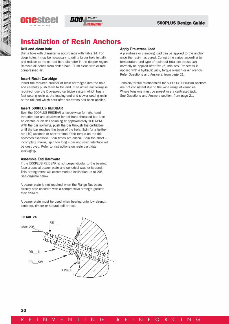
Assemble End HardwareIf the 500PLUS REIDBAR is not perpendicular to the bearingface a special bearer plate and spherical washer is used.This arrangement will accommodate inclination up to 20°.See diagram below.
A bearer plate is not required when the Flange Nut bearsdirectly onto concrete with a compressive strength greaterthan 25MPa.
A bearer plate must be used when bearing onto low strengthconcrete, timber or natural soil or rock.
Apply Pre-stress LoadA pre-stress or clamping load can be applied to the anchoronce the resin has cured. Curing time varies according totemperature and type of resin but total pre-stress cannormally be applied after five (5) minutes. Pre-stress isapplied with a hydraulic jack, torque wrench or air wrench.Refer Questions and Answers, from page 21.
Tension/torque relationships for 500PLUS REIDBAR Anchorsare not consistent due to the wide range of variables.Where tensions must be preset use a calibrated jack.See Questions and Answers section, from page 21.
Installation of Resin Anchors
Max 20°RB___
RB___N
RB___SW
B Plate
DETAIL 24

500PLUS Design Guide
31
R E I N V E N T I N G R E I N F O R C I N G
There are several methods available to anchor 500PLUSREIDBAR into concrete or other homogenous substrates.Starter bars are frequently located in critical stress zonesand consequently the following tables are based on the NZ3101:1995 requirement that bars in these zones develop thefull breaking strength of the bar at the interface of the newand old concrete. (This exceeds the less stringentrequirements of AS 3600 which suggests 1.1fy).
If starter bars are not in a critical stress zone, i.e. floortopping starters which will act mainly in shear, the holedepths and amount of resins can be reduced.
As a general rule, REID epoxy and polyester injection systemsas well as standard glass phials can be expected to developa approximately 14MPa adhesion between the resin plug anda good quality 30MPa concrete substrate. Hammer-in glasscapsules can be expected to provide approximately 12MPaadhesion.
Three common methods used to anchor 500PLUS REIDBARinto existing stone or concrete:
METHOD 1 -USING REID ‘HAMMER IN’ CAPSULES
DescriptionREID ‘Hammer In’ Capsules will anchor 500PLUS REIDBARinto rock, concrete or other homogeneous substrates.
Because of the unique design of the glass capsules the500PLUS REIDBAR can be simply hammered into the drilledhole in the substrate without any spinning of the bar.
The glass capsule contains a measure of resin and hardenerwith the hardener arranged in such a way that mixing willoccur without the need to spin the bar.
Directions for Use1. Holes of the correct diameter and depth should be drilledusing good quality drilling equipment, e.g. REID MultishankCarbide Drills.
2. Drilling debris and dust should be thoroughly cleaned fromthe hole using a suitable technique such as the stiff nylonbottle brushes available from REID. Compressed air orclean water is also commonly used.
3. Once the hole is prepared insert the correct capsule (orcapsules).
4. Hammer the end of the 500PLUS REIDBAR through theglass capsule until the bar reaches the bottom of thehole.
Caution: Always wear safety glasses when using hammer-incapsules
Anchoring into Existing Concrete
TABLE 17Capsule details. Note: Concrete strength min 30MPa
500PLUS Hole *Recom Number of **Curing timeREIDBAR size Diameter hole depth Capsule capsules @ 20°C
RB12 18 134 HIC12/CAC 2 1 hour
RB16 25 191 HIC/CAC16 2 1 hour
Note: 1. Hole depths given achieve bar ultimate strength.2. * Hole depths can be halved and a single Hammer In Capsule used where the 500PLUS REIDBARS are located in non-critical stress zones.3. Hole diameter is critical to load transfer.4. **Temperature of substrate.

500PLUS Design Guide
32
R E I N V E N T I N G R E I N F O R C I N G
METHOD 2 -USING REID CHEMICAL INJECTION SYSTEMS
DescriptionREID offers a range of high strength epoxy and polyesterchemical injection systems which will anchor 500PLUSREIDBAR into rock, concrete or other homogeneoussubstrates.All of these systems utilise cartridges with self-mixing nozzlesthat automatically mix the resins and hardeners as theproduct is gunned into the drilled hole.
Directions for Use1. Holes of the correct diameter and depth should be drilledusing good quality drilling equipment, e.g. REID Multi-shank Carbide Drills.
2. Drilling debris and dust should be thoroughly cleaned fromthe hole using a suitable technique such as the stiff nylonbottle brushes available from REID. Compressed air orclean water is also commonly used.
3. Once the hole is prepared insert the nozzle of theinjection gun into the hole and inject the resin into thebase of the hole.
4. Push the 500PLUS REIDBAR through the mixed resin andhardener until the bar reaches the bottom of the hole.Rotate the bar four times by hand in an anti-clockwisedirection.
Anchoring into Existing Concrete
TABLE 18Resin details. Note: Concrete strength min 30MPa
SWIFTCHEM 3+3 RIC 12 EPOXY RIC24 EPOXY
500PLUS Hole *Recom. **Curing time Approx **Curing time Approx **Curing time ApproxREIDBAR dia. depth @ 20°C holes @ 20°C holes @ 20°C holessize mm hole mm per pack per pack per pack
(Epoxy/Conc Bond (Epoxy/Concrete Bond (Epoxy/Concrete BondStress 11.7MPa) Stress 11.7MPa) Stress 15MPa)
RB12 18 134 1 hour 60 2 hours 100 24 hours 100
RB16 25 191 1 hour 35 2 hours 55 24 hours 55
RB20 27 239 1 hour 10 2 hours 15 24 hours 15
RB25 32 292 1 hour 6 2 hours 10 24 hours 10
RB32 40 382 1 hour 3 2 hours 5 24 hours 5
Note: 1. Hole depths given achieve bar ultimate strength.2. *Hole depths can be reduced where the 500PLUS REIDBARs are located in non-critical stress zones.3. Hole diameter is critical to load transfer.4. **Temperature of substrate.
500PLUS Design Guide
33
R E I N V E N T I N G R E I N F O R C I N G
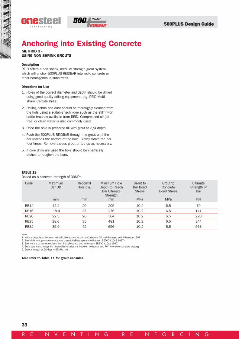
METHOD 3 -USING NON SHRINK GROUTS
DescriptionREID offers a non shrink, medium strength grout systemwhich will anchor 500PLUS REIDBAR into rock, concrete orother homogeneous substrates.
Directions for Use
1. Holes of the correct diameter and depth should be drilledusing good quality drilling equipment, e.g. REID Multi-shank Carbide Drills.
2. Drilling debris and dust should be thoroughly cleaned fromthe hole using a suitable technique such as the stiff nylonbottle brushes available from REID. Compressed air (oil-free) or clean water is also commonly used.
3. Once the hole is prepared fill with grout to 3/4 depth.
4. Push the 500PLUS REIDBAR through the grout until thebar reaches the bottom of the hole. Slowly rotate the barfour times. Remove excess grout or top up as necessary.
5. If core drills are used the hole should be chemicallyetched to roughen the bore.
Anchoring into Existing Concrete
TABLE 19Based on a concrete strength of 30MPa
Code Maximum Recom’d Minimum Hole Grout to Grout to UltimateBar OD Hole dia. Depth to Reach Bar Bond Concrete Strength of
Bar Ultimate Stress Bond Stress BarStrength
mm mm mm MPa MPa KN
RB12 14.2 20 205 10.2 6.5 79
RB16 18.4 25 276 10.2 6.5 141
RB20 22.5 28 384 10.2 6.5 220
RB25 28.6 35 481 10.2 6.5 344
RB32 35.9 42 656 10.2 6.5 563
Note: 1. Value extrapolated between Hemel Laboratories report on Conbextra GP and Restrapo and Wilkenson 19972. Bars O/D to edge concrete not less than 4db (Restrapo and Wilkenson SE50C V10c2 1997)3. Bars centre to centre not less than 8db (Restrapo and Wilkenson SE50C V10c2 1997)4. Extra care must always be taken with installations between horizontal and 70° to ensure complete wetting5. Grout strength at 28 days = 65MPa min
Also refer to Table 11 for grout capsules

500PLUS Design Guide
34
R E I N V E N T I N G R E I N F O R C I N G
Bracing & Tie DownFeatures and benefitsBracing:• Simple bracing system for all applications where rodbracing can be used.
• Very cost effective – saves time and money overtraditional methods.
• Uses standard end fittings and 500PLUS REIDBAR.
• No more welding of special fittings for bracing assemblies.
• No more threading of bar or rod.
• No more fabrication of bracing components.
• Versatile – a range of standard end connections used withstandard 500PLUS REIDBAR fits most applications andsituations.
• May be galvanized and used with galvanized 500PLUSREIDBAR for added durability.
Tie down:• 500PLUS REIDBAR provides cost effective solution totransfer tension/uplift forces to secure supports e.g. roofto foundation connection.
• Suits most construction methods and materials.
• The REID range of chemical anchors and 500PLUSREIDBAR fittings allow a variety of solutions for anchoring500PLUS REIDBAR to concrete foundations/ supports.
• Standard 500PLUS REIDBAR, nuts and associatedcomponents of the 500PLUS REIDBAR system are readilyavailable and do not require additional preparation.
• No more welding of special fittings for bracing assemblies.
• No more threading of bar or rod.

500PLUS Design Guide
R E I N V E N T I N G R E I N F O R C I N G
500PLUS REIDBAR is ideal for use as wind bracing in alltypes of building construction. Because the bar is threadedalong its full length it overcomes the problems of having toprefabricate conventional tie bars and site weld anchoragecleats to close tolerances.
Example: A tilt-up building wall resits lateral wind/seismicloads by means of a cantilevered footing and an in-planetruss at roof level.
Typical detail atrafter connection
Use Reids Liebig anchors
DETAIL 25
DETAIL 26
Max load in diagonal tie = (24-6) x √152 + 6215
= 19.4 kN
Use RB12 diagonal tension ties
R=2kN/m
W=0.5kPa
R=2kN/m
Wind Bracing
36

500PLUS Design Guide
36
R E I N V E N T I N G R E I N F O R C I N G
500PLUS REIDBARS are ideal for tie-down bars for lightweightmasonry, brick, steel framed, timber framed or solid timberstructures.
In extreme wind conditions such as Northern Australia 12mm500PLUS REIDBAR (RB12) greatly simplifies compliance withbuilding code requirements for cyclone tie-downs for all typesof building construction.
Using designers can simply and economically provide acontinuous tie from the building footing to roof truss that caneven be post tensioned to improve the structuralperformance of the wall unit.
Post tensioning wall ties can provide many advantages.
• Reduces flexural tensile stress in masonry walls.
• Improves stiffness of wall diaphrams.
• Reduces the likelihood of leakage due to shrinkage cracksin concrete or masonry.
• Reduces deflections in structural elements.
• Reduces thermal movement in solid timber constructionsystems.
Tie Down Bars
Masonry
DETAIL 27
L Bkt
RB12TN
RB12 bar
RB12TI
Timberframing
Solidtimber

500PLUS Design Guide
37
R E I N V E N T I N G R E I N F O R C I N G
WELDINGFeatures and benefits• 500PLUS REIDBAR systems are designed to eliminate orreduce the need to weld reinforcing bars. Site conditionscan often make it difficult to control both weldingprocedures and proper consumable selection.
References, standardsAS1554 Part 3 1983 and the WTIA technical note 1.
Joint designRefer to AS1554 Part 3
Choice of welding processThis grade of steel is readily weldable by either metal manualarc (MMA) or semi-automatic and automatic (SUBARC) orinert gas shielded (MIG) processes.
Optimum results are obtained with MIG and automaticprocesses.
ConsumablesWhen using MMA welding processes, we recommend the useof Hydrogen Controlled electrodes.
Note: 500PLUS REIDBAR 12mm origin is micro alloyed bar and can be welded using the procedures outlined. 500PLUSREIDBAR 16-32mm is manufactured by the TEMPCORE process and can be welded using the procedures outlined.

500PLUS Design Guide
38
R E I N V E N T I N G R E I N F O R C I N G
Concrete reinforcing and weldingCareful design, process specification, qualification andcontrol is vital for the integrity of weldments.Welding processes can produce undesirable metallurgicaldefects in the steels being welded and in other adjacentmaterials subject to arc strikes and weld spatter. Defectsintroduced during welding can embrittle steel and providedsites which act as stress concentrators, causing unexpectedmodes of failure. For this reason some codes prohibit, orrestrict the welding of reinforcing bars used in concreteconstruction.
As a general rule we do not recommend welding ofreinforcing bars – especially on site where the required levelof quality and supervision can be difficult to maintain. Wherewelding is required it should be critically supervised andcarried out under carefully controlled conditions by suitablyqualified welders and welding processes. Where bars are tobe positioned in pre-fabricated cages, consideration shouldbe given to tying rather than welding bars. Mechanicalconnection of bars using the benefits of 500PLUS REIDBARprovide effective alternatives for joining bars both in thefactory and on site.
Effect of heating on mechanical propertiesThere are two methods for achieving the required mechanicalstrengths of reinforcing bars:
• Addition of alloying elements to the steel
• Thermally treating the bar (cold water quenching andtempering)
Bars which are cold worked or thermally treated to increasetheir strength, loose mechanical strength after heating. Thesebars cannot be heated before bending and can be adverselyaffected by welding processes. Great care and control mustbe exercised when applying heat to such bars to ensure thatthey do not exceed the critical heating temperature at anypoint. This is recognised by AS3600 Clause 19.2.3.1 whichlimits the design strength to 250MPa for bars heated inexcess of 450°C.
RB12 500PLUS REIDBAR is microalloyed and retains its fullstrength and ductility on cooling after being heated totemperatures in excess of 600°C.
RB12 500PLUS REIDBAR may be heated to assist bendingwithout risk of reducing the mechanical properties, unlikecold worked or thermally treated bars.
See Questions and Answers section, pages 21-22.
RB12 MICROALLOYWelding arc energy (heat input)We recommend that a minimum welding arc energy of2kJ/mm be used for all processes.
The use of well controlled, high heat input processes isespecially important for tack welds, to reduce the risk forundesirable hardening in the heat affected zones adjacent tothe welds.
Choose the largest diameter electrode possible for the job.
The electrode chosen should never be less than 3.2mmAs a guide the following minimum electrode sizes should beused for all welds including tack welds:
Electrode diameters.
TABLE 20
500PLUS REIDBAR Minimum electrodediameter diameter
12, 16, 20 3.25
25, 32 4
over 32 5-6

500PLUS Design Guide
39
R E I N V E N T I N G R E I N F O R C I N G
RB12 MICROALLOY
Tack WeldsTack welds should be made with high heat inputs. In practice,this may be achieved by selecting the largest possible size ofelectrode to ensure adequate heat input.
AS 1554 provides appropriate requirements for tack welds.We recommend that tack welds on large diameter bars bemade by MIG processes. In practice it is doubtful that tackwelds on bars larger than 25 mm would be made with MMA.
PreheatingHeating of steels prior to welding reduces the risk of crackingin the heat affected zones.
Regardless of the grade of steel, the best welds are achievedwhen the steel temperature prior to welding is at least 20-25°C.
Welds should never be attempted at temperatures below 0°Cwithout preheating. In cold weather where such temperaturesare expected it is essential to preheat the steel to 20-25°C.Whilst good quality welds can be achieved in many steels atambient temperatures above 0°C, the weldability andresistance to cracking depends on the steel chemistry and anumber of factors which influence the rate of cooling from thewelding temperature. These include the initial temperature of
the steel, the physical size and mass of the pieces beingjoined, the size and shape of the weld, the welding heat inputand the ambient temperature.
No additional preheat is required for any size of 500PLUSREIDBAR when the welding arc energy exceeds 2kJ/mm.
Bars of 32mm diameter and larger require higher levels ofpreheat only when welded with arc energies less than2kJ/mm. In practice it is unlikely that such low arc energieswould be used for welding bars of this size.
< 25 < Preheat not required
32 25
40 50Preheat not required
50 75 50 Preheat not required
Electrode diameter
3.25 4 4 5 6
Arc energy kJ/mm E 1< E < 1.5 1.5 < E < 2.0 2.0 < E < 2.5 2.5 < E < 3.5 3.5 < E
Electrode diameter
3.25 4 5 6
< 25 Preheat not required
32 50 Preheat not required
40 75 50
50 100 75 Preheat not required
Hydrogen controlled electrodes (EXX15, EXX16, EXX18, EXX28, EXX48)or semi-automatic and automatic welding processes
Metal manual arc welding with non-hydrogen controlled electrodes (EXX10, EXX11, EXX12, EXX13, EXX14, Exx20, EXX24, Exx27)
Bar diameter Preheat temperature °C
Bar diameter Preheat temperature °C

500PLUS Design Guide
40
R E I N V E N T I N G R E I N F O R C I N G
500N 500PLUS REIDBAR produced by the TEMPCOREprocess has a carbon equivalent (CE) limit of 0.44 max and,as such, requires no pre-heating prior to welding.
Users should also be aware that hydrogen controlledelectrodes will be required for all weld types, andmatching strength electrodes will be required for butt welds.
GENERAL RULES FOR THE WELDING OF 500N500PLUS REIDBARAll welding must conform to the requirements of AS/NZS1554 part 3, 2002.
PreheatNot required
Post HeatNot required
Electrode Type• Hydrogen controlled welding processes and electrodessuch as GMAW (MIG), FCAW and low hydrogen MMAW(sticks) must be used for all weld types. Correct control,storage and drying of electrodes is essential.
• Matching strength W55x (E55xx) or W62x (E62xx) typeconsumables are required for all load bearing butt welds.
• Under-matching W50x (E48xx) and W41 (E40xx)electrodes may also be used for lap and other weld typeswith appropriate weld lengths as shown in the followingsections.
• Select electrode diameter to be compatible with size ofbars being joined.
Interpass TemperatureThis should be limited to 200°C maximum for all joints.
Welding Technique & heat InputBest results are achieved using stringer beads where heatinput will generally not exceed 2.5kj/mm. Weaving is notrecommended.
Welding Practice Notes• Observe 200°C maximum limit on interpass temperaturesfor TEMPCORE.
• For multiple welds, interpass temperature rise can beminimised by laying weld beads on separate joints insequence thus allowing each weld to cool between runs.As interpass temperatures are likely to increasethroughout, check the interpass temperature prior tocommencing each weld run.
• Balance welding on each side of joint as required tominimise distortion.
• For butt welds, back grind root run prior to completing thejoint.
• Clean and dress each weld run prior to deposition ofsubsequent runs.
• Refer to electrode manufacturer’s recommended currentranges and shielding gasses.
General NotesNon-symmetric joints such as lap welds may not be suitablefor use in seismic applications – specialist advice should besought in such cases.
RB16-32 TEMPCORE

500PLUS Design Guide
41
R E I N V E N T I N G R E I N F O R C I N G
Locational TackWeldsElectrode TypeUnder-matching strength electrodesare preferred but matching strengthmay be used.
Weld LengthNot less than the size of the smallerbar.
General NotesThese are usually used forpositioning and holding purposes,and in prefabricated elements.
They must not be used for liftingpurposes unless prior approval hasbeen obtained from the designengineer (see AS/NNS 1554.3).They do not affect the strength of500PLUS.
Double Sided TackWeldsElectrode TypeMatching and under-matchingstrength electrodes may be used.
Weld LengthMinimum total weld length is 5d
General NotesThe short length of conventionaldouble sided lap splice welds maycause excessive rotation at thesplice when loaded in tension, andthus contribute to concrete spalling.Longer weld lengths than thatrequired to develop full strength havetherefore been recommended. Thistendency to rotate can be furtherminimised by forming the weld in twoparts as shown, thus increasing theeffective geometric length. In thiscase, the gap between lap weldsshould not exceed the total weldlength.
Single Sided LapWeldsElectrode TypeMatching and under-matchingstrength electrodes may be used.
Weld length• Matching strength electrodes: 8d• Under-matching W50x (E48xx) typeelectrodes: 9d
• Under-matching W41x (E41xx) typeelectrodes: 10d
General NotesSingle sided lap welds, because oftheir greater length, have lesstendency to rotate, but should onlybe used with the permission of thesupervising engineer when access tothe second side is not available orimpractical. These welds may alsobe formed in two parts as shownprovided total weld lengths noted areused.
Strap WeldsElectrode TypeMatching and under-matchingstrength electrodes may be used.
Weld LengthsWelded one side: 5d for eachindividual weldWelded both sides: 3d for eachindividual weld
General NotesFull parent bar properties aregenerated by strap welds. The totalsectional area of the splice barsmust not be less than the crosssectional area of the parent bar.
The gap between parent bars mustnot exceed 20mm.
Strap welds may be welded either onone side or both sides notingminimum effective weld lengthsabove. Strap welds are bulkier thanlap or butt splice joints thus may notbe suitable for use in applicationswhere concrete cover is minimal.Where doubt exists, verify suitabilitywith the supervising engineer.
Butt WeldsElectrode TypeMatching strength electrodes areessential to develop full strength inthe butt weld.
General NotesObserve 200°C maximum interpasstemperature by allowing weld to coolbetween runs, particularly towardsend of welding for TEMPCORE.
RB16-32 TEMPCORE
500PLUS Design Guide
ACTCanberra OneSteel Reinforcing17 Sheppard Street Hume ACT 2620Phone: 02 6260 1244 Fax: 02 6260 1286
New South WalesAlbury OneSteel Reinforcing327 Kiewa Street, Albury NSW 2640Phone: 02 6021 1466 Fax: 02 6041 1594Central Coast OneSteel ReinforcingCnr Gavenlock Rd & Marklea Close,Tuggerah NSW 2259 Phone: 02 4351 1077 Fax: 02 4351 1075
Coffs Harbour OneSteel Reinforcing c/- OneSteel MetalandCnr Elswick & Isles Drive, Coffs Harbour NSW 2450 Phone: 02 6652 3744 Fax: 02 6652 4226
Lismore OneSteel Reinforcing c/- OneSteel Metaland39-41 Habib Drive, Lismore South NSW 2480Phone: 02 6621 8722 Fax: 02 6621 8497
McGraths Hill OneSteel Reinforcing38 Park Road, McGraths Hill NSW 2756Phone: 02 4587 9679 Fax: 02 4587 9122
Newcastle OneSteel Reinforcing15 Statham Street, Bennetts Green NSW 2290Phone: 02 4948 7433 Fax: 02 4947 2084
Orange OneSteel Reinforcing5 Stephens Place, Orange NSW 2800Phone: 02 6362 2299 Fax: 02 6362 4994
Port Macquarie OneSteel Reinforcing10 Belah Road, Port Macquarie NSW 2444Phone: 02 6581 1144 Fax: 02 6581 1181
Revesby OneSteel Reinforcing Service CentreGate 3 Mons Road, Revesby NSW 2212Phone: 02 9792 9062 Fax: 02 9792 1971
Smeaton Grange OneSteel Reinforcing2-4 Bluett Drive, Smeaton Grange NSW 2567 Phone: 02 4648 1691 Fax: 02 4648 1311
Tamworth OneSteel Reinforcing c/- OneSteel Metaland26-30 Goonan Street, West Tamworth NSW 2340Phone: 02 6765 4044 Fax: 02 6765 2552
Wagga Wagga OneSteel ReinforcingCnr Say & Schiller Streets, Wagga Wagga NSW 2650Phone: 02 6921 4178 Fax: 02 6921 7069
Wetherill Park OneSteel Reinforcing14 Walker Place, Wetherill Park NSW 2164Phone: 02 9725 1799 Fax: 02 9756 1168
Wollongong OneSteel Reinforcing14-16 Lady Penrhyn Drive, Unanderra NSW 2526Phone: 02 4272 9889 Fax: 02 4271 8718
Northern TerritoryDarwin OneSteel ReinforcingLot 1611 Bombing Road, Winnellie NT 0820Phone: 08 8947 0330 Fax: 08 8947 0358
QueenslandBrisbane OneSteel Reinforcing220 Bradman Street, Acacia Ridge QLD 4110Phone: 07 3845 5655 Fax: 07 3845 5697
Cairns OneSteel ReinforcingLot 25 Hargreaves Street, South Cairns Industrial Estate, Edmonton QLD 4869Phone: 07 4045 5955 Fax: 07 4045 5922
Carole Park OneSteel Reinforcing23-25 Argon Street, Carole Park QLD 4300Phone: 07 3271 2099 Fax: 07 3271 2950
Cleveland OneSteel ReinforcingLot 11 Freeth Street, Cleveland QLD 4163Phone: 07 3821 3222 Fax: 07 3821 3233
Gladstone OneSteel Reinforcing c/- OneSteel MetalandBensted Street, Gladstone QLD 4680Phone: 07 4972 8033 Fax: 07 4972 8066
Gold Coast OneSteel ReinforcingCnr Precision Drive & Barnett Place, Ernest QLD 4214Phone: 07 5594 0599 Fax: 07 5594 0495
Mackay OneSteel Reinforcing7 David Muir Street, Slade Point QLD 4740Phone: 07 4955 1922 Fax: 07 4955 2183
Maroochydore OneSteel Reinforcing517 Maroochydore Rd, Kunda Park QLD 4556Phone: 07 5445 1561 Fax: 07 5445 1038
Rockhampton OneSteel Reinforcing88 Hollingsworth Street, North Rockhampton QLD 4701Phone: 07 4927 9155 Fax: 07 4922 2773
Strathpine OneSteel Reinforcing8 Duntroon Street, Strathpine QLD 4500Phone: 07 3205 6766 Fax: 07 3205 4722
Toowoomba OneSteel ReinforcingLot 4 Production Court, Toowoomba QLD 4350Phone: 07 4633 3800 Fax: 07 4633 3690
Townsville OneSteel Reinforcing399 Bayswater Road, Garbutt QLD 4814Phone: 07 4775 5100 Fax: 07 4775 1222
South AustraliaAdelaide OneSteel Reinforcing519 Cross Keys Road, Cavan SA 5094Phone: 08 8349 8666 Fax: 08 8349 7555
TasmaniaHobart OneSteel Reinforcing9 Sunmont Street, Derwent Park TAS 7009Phone: 03 6273 0300 Fax: 03 6273 0315
Launceston OneSteel Reinforcing36b Murphy Street, Invermay TAS 7248Phone: 03 6334 3410 Fax: 03 6334 3412
VictoriaAltona North OneSteel Reinforcing2-22 Kyle Road, Altona North VIC 3025Phone: 03 9207 2200 Fax: 03 9207 2270
Campbellfield OneSteel Reinforcing58-60 Killara Road, Campbellfield VIC 3062Phone: 03 9357 8855 Fax: 03 9357 8292
Dandenong OneSteel ReinforcingFactory 3/1 Abbots Road, Dandenong VIC 3175Phone: 03 9706 4321 Fax: 03 9706 4235
Geelong OneSteel Reinforcing2 Hayworth Court, Breakwater VIC 3219Phone: 03 5248 3500 Fax: 02 5248 6315
Horsham OneSteel Reinforcing36 Hamilton Road, Horsham VIC 3400Phone: 03 5382 3192 Fax: 03 5381 1173
Ringwood OneSteel ReinforcingFactory 10/505 Maroondah HighwayRingwood VIC 3134Phone: 03 9879 5360 Fax: 03 9879 0575
Western AustraliaPerth OneSteel Reinforcing53 Harrison Road, Forestfield WA 6058Phone: 08 6332 3111 Fax: 08 6332 3149
Head OfficeNational Office OneSteel ReinforcingLevel 6, 205 Pacific Highway, St Leonards NSW 2065Phone: 02 8424 9800 Fax: 02 9966 0702
[email protected] www.reinforcing.comThis information is provided as a service to those interested in steel reinforcement. Since the information is provided for general guidance only, and in no way replaces the
services of professional consultants on particular projects or subjects, no legal liability can be accepted by OneSteel Reinforcing Pty Limited for its use.
500PLUS REIDBAR, 500PLUS REBAR and TEMPCORE are trademarks authorised for use by OneSteel Reinforcing Pty Limited ABN 22 004 148 289.
New South WalesTel: 02 9794 1000Fax: 02 9772 1689
Western AustraliaTel: 08 6332 3111Fax: 08 6332 3179
VictoriaTel: 03 9207 2200Fax: 03 9207 2270
Northern TerritoryTel: 08 8947 0330Fax: 08 8947 0358
QueenslandTel: 07 3845 5655Fax: 07 3845 5697
TasmaniaTel: 03 6273 0300Fax: 03 6273 0315
South AustraliaTel: 08 8349 8666Fax: 08 8349 7555
ACTTel: 02 6260 1244Fax: 02 6260 1286
National Head Office: Locked Bag 3050, Artarmon NSW 1570. Telephone: (61 2) 8424 9800. Facsimile: (61 2) 9966 0702
OSR437