+2 01229689304 - Aci Farfisa Intercoms - ACIFARFISA Technology in Evolution - Egypt
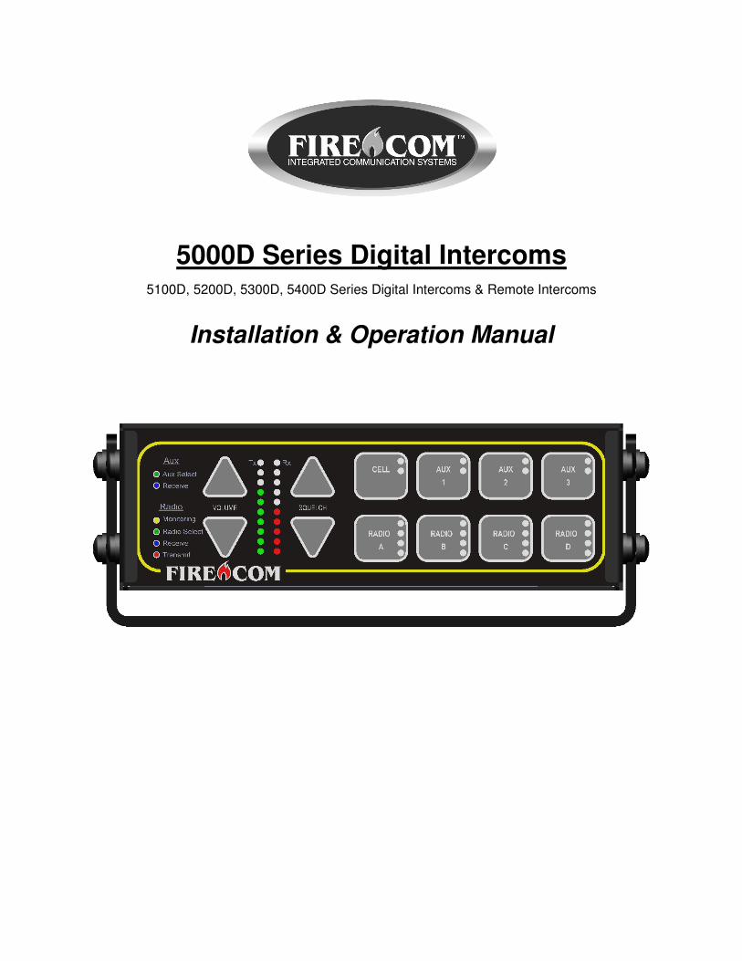
5000D Series Digital Intercoms 5100D, 5200D, 5300D, 5400D Series Digital Intercoms & Remote Intercoms
Installation & Operation Manual
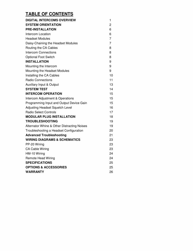
TABLE OF CONTENTS
DIGITAL INTERCOMS OVERVIEW 1
SYSTEM ORIENTATION 2
PRE-INSTALLATION 6
Intercom Location 6
Headset Modules 7
Daisy-Chaining the Headset Modules 7
Routing the CA Cables 8
Intercom Connections 8
Optional Foot Switch 8
INSTALLATION 9
Mounting the Intercom 9
Mounting the Headset Modules 9
Installing the CA Cables 10
Radio Connections 11
Auxiliary Input & Output 13
SYSTEM TEST 14
INTERCOM OPERATION 15
Intercom Adjustment & Operations 15
Programming Input and Output Device Gain 15
Adjusting Headset Squelch Level 16
Radio Select Controls 17
MODULAR PLUG INSTALLATION 18
TROUBLESHOOTING 19
Alternator Whine & Other Distracting Noises 19
Troubleshooting a Headset Configuration 20
Advanced Troubleshooting 21
WIRING DIAGRAMS & SCHEMATICS 23
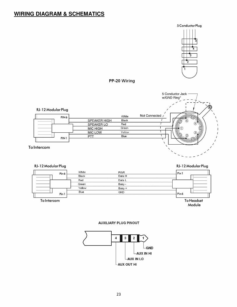
PP-20 Wiring 23
CA Cable Wiring 23
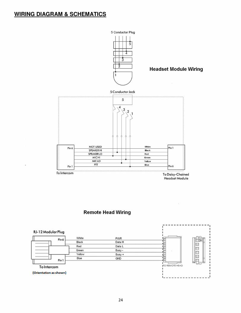
HM-10 Wiring 24
Remote Head Wiring 24
SPECIFICATIONS 25
OPTIONS & ACCESSORIES 25
WARRANTY 26
1
DIGITAL INTERCOMS OVERVIEW
5000D Series Digital Intercoms
The Firecom 5000D Series Digital Intercoms, when used with Firecom noise attenuating headsets, provide protection from hearing loss
that can occur from exposure to high noise levels, while also providing each user clear communication with the other crew members.
New Features:
• Squelch control
• Programmable from the faceplate
• Models available for 1, 2, 3, or 4 radios
• 90dB SNR audio quality
• Waterproof remote intercom head for outdoor installations.
Each crew member will hear all radio traffic and be able to communicate over the intercom. Crew members wearing Radio-Transmit
headsets may transmit over the apparatus radio from any headset position in the system. “Intercom Only” headsets will not transmit
over the radio.
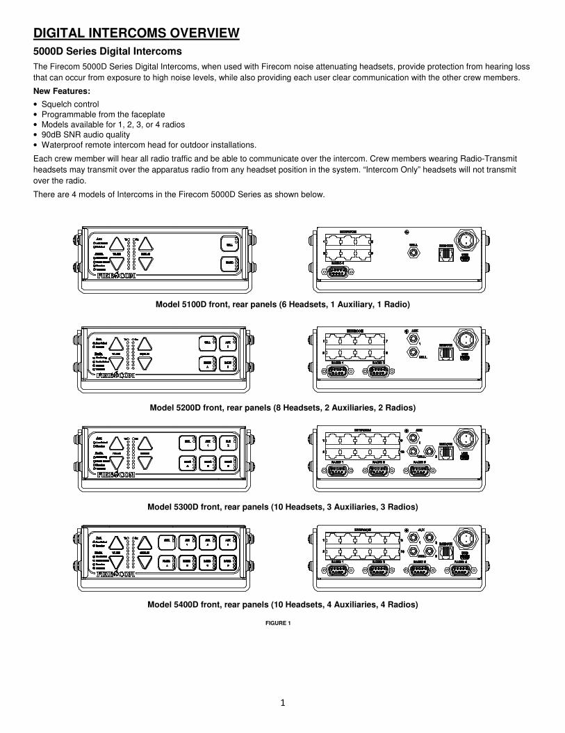
There are 4 models of Intercoms in the Firecom 5000D Series as shown below.
Model 5100D front, rear panels (6 Headsets, 1 Auxiliary, 1 Radio)
Model 5200D front, rear panels (8 Headsets, 2 Auxiliaries, 2 Radios)
Model 5300D front, rear panels (10 Headsets, 3 Auxiliaries, 3 Radios)
Model 5400D front, rear panels (10 Headsets, 4 Auxiliaries, 4 Radios)
FIGURE 1

2
SYSTEM ORIENTATION This section provides an overview of the 5000D Series Digital Intercom System and an introduction to its individual components. Figure 2 shows a typical system. Refer to this diagram for each component.
INTERCOM The main control unit for the 5000D Series Intercom System which contains all the controls and interface circuitry.
WIRELESS BASE STATION A Module which provides wireless communications between wireless headset users, belt pack users, and intercom and radio users.
2-WAY RADIO The existing 2-way radio in the apparatus.
MOBILE RADIO INTERFACE CABLE Provides the interface connections between the 5000D Series Digital Intercom and the 2-way radio in the apparatus. The cable needed depends on the make and model of your radio. Contact your local Firecom Dealer for more information regarding an Interface Cable specific to your radio.
POWER CABLE ASSEMBLY Provides the power connections for the 5000D Series Intercom Unit. The power connections should be made at the same place as the power connections for your radio.
HM-10 HEADSET MODULES The wired headset will be plugged into the Headset Module (HM-10) which is the standard module for headset-to-system interface.
PP-20 PUMP PANEL MODULE A water-resistant Headset Module used on the exterior of the apparatus (e.g. at the Pump Panel, at the tail-board, etc.).
CA CABLES Six-conductor flat cable which connects the 5000D Series Digital Intercom to the Wireless Base Station, HM-10, PP-20 Headset Modules, Remote Head, and Radio.
REMOTE HEAD INTERCOMS Remote Intercoms can be connected to the main control unit to control the unit from a remote location. Up to 5 remotes heads can be connected to the digital intercom by utilizing an RJ-12 splitter or by splicing into the 6 conductor modular cable.
FIGURE 2
3
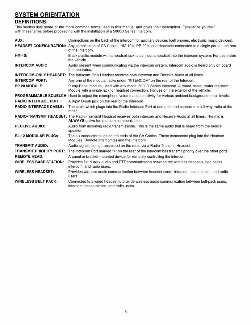
SYSTEM ORIENTATION DEFINITIONS: This section lists some of the more common terms used in this manual and gives their description. Familiarize yourself with these terms before proceeding with the installation of a 5000D Series Intercom.
AUX: Connections on the back of the intercom for auxiliary devices (cell phones, electronic music devices).
HEADSET CONFIGURATION: Any combination of CA Cables, HM-10’s, PP-20’s, and Headsets connected to a single port on the rear of the intercom.
HM-10: Black plastic module with a headset jack to connect a headset into the intercom system. For use inside the vehicle.
INTERCOM AUDIO: Audio present when communicating via the intercom system. Intercom audio is heard only on board the apparatus.
INTERCOM-ONLY HEADSET: The Intercom-Only Headset receives both intercom and Receive Audio at all times.
INTERCOM PORT: Any one of the modular jacks under “INTERCOM” on the rear of the Intercom.
PP-20 MODULE: Pump Panel module, used with any model 5000D Series Intercom. A round, metal, water resistant Module with a single jack for headset connection. For use on the exterior of the vehicle.
PROGRAMMABLE SQUELCH: Used to adjust the microphone volume and sensitivity for various ambient background noise levels.
RADIO INTERFACE PORT: A 9-pin D-sub jack on the rear of the Intercom.
RADIO INTERFACE CABLE: The cable which plugs into the Radio Interface Port at one end, and connects to a 2-way radio at the other.
RADIO-TRANSMIT HEADSET: The Radio-Transmit Headset receives both intercom and Receive Audio at all times. The mic is ALWAYS active for intercom communication.
RECEIVE AUDIO: Audio from incoming radio transmissions. This is the same audio that is heard from the radio’s speaker.
RJ-12 MODULAR PLUGs The six conductor plugs on the ends of the CA Cables. These connectors plug into the Headset Modules, Remote Intercom(s) and the Intercom.
TRANSMIT AUDIO: Audio signals being transmitted on the radio via a Radio-Transmit Headset.
TRANSMIT PRIORITY PORT: The Intercom Port marked “1” on the rear of the intercom has transmit priority over the other ports.
REMOTE HEAD: A panel or bracket-mounted device for remotely controlling the intercom.
WIRELESS BASE STATION: Provides full-duplex audio and PTT communication between the wireless headsets, belt-packs, intercom, and radio users.
WIRELESS HEADSET: Provides wireless audio communication between headset users, intercom, base station, and radio users.
WIRELESS BELT PACK: Connected to a wired headset to provide wireless audio communication between belt-pack users, intercom, bases station, and radio users.
4
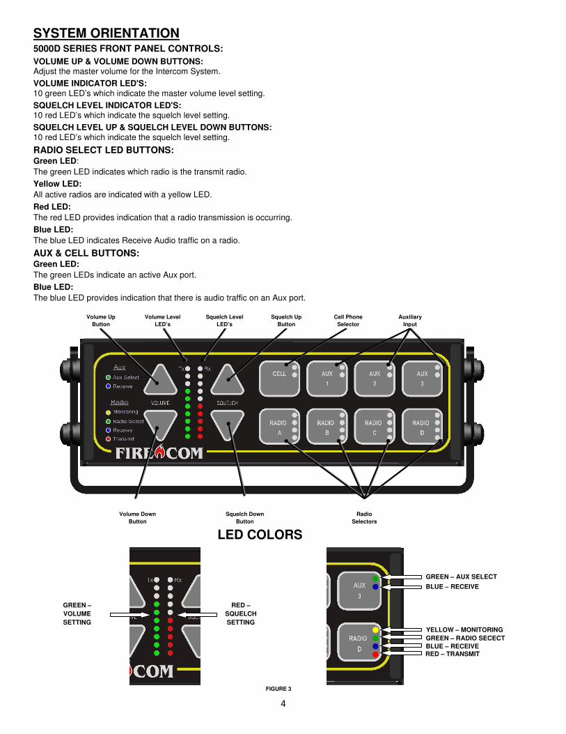
SYSTEM ORIENTATION 5000D SERIES FRONT PANEL CONTROLS:
VOLUME UP & VOLUME DOWN BUTTONS: Adjust the master volume for the Intercom System.
VOLUME INDICATOR LED'S: 10 green LED’s which indicate the master volume level setting.
SQUELCH LEVEL INDICATOR LED'S: 10 red LED’s which indicate the squelch level setting.
SQUELCH LEVEL UP & SQUELCH LEVEL DOWN BUTTONS: 10 red LED’s which indicate the squelch level setting.
RADIO SELECT LED BUTTONS: Green LED:
The green LED indicates which radio is the transmit radio.
Yellow LED:
All active radios are indicated with a yellow LED.
Red LED:
The red LED provides indication that a radio transmission is occurring.
Blue LED:
The blue LED indicates Receive Audio traffic on a radio.
AUX & CELL BUTTONS: Green LED:
The green LEDs indicate an active Aux port.
Blue LED:
The blue LED provides indication that there is audio traffic on an Aux port.
Squelch Up
Button
Squelch Down
Button
Volume Level
LED’s
Cell Phone
Selector
Squelch Level
LED’s
Volume Up
Button
Auxiliary
Input
Radio
Selectors
Volume Down
Button
GREEN – AUX SELECT
BLUE – RECEIVE
YELLOW – MONITORING
GREEN – RADIO SECECT
BLUE – RECEIVE RED – TRANSMIT
GREEN –
VOLUME
SETTING
RED –
SQUELCH
SETTING
LED COLORS
FIGURE 3
5
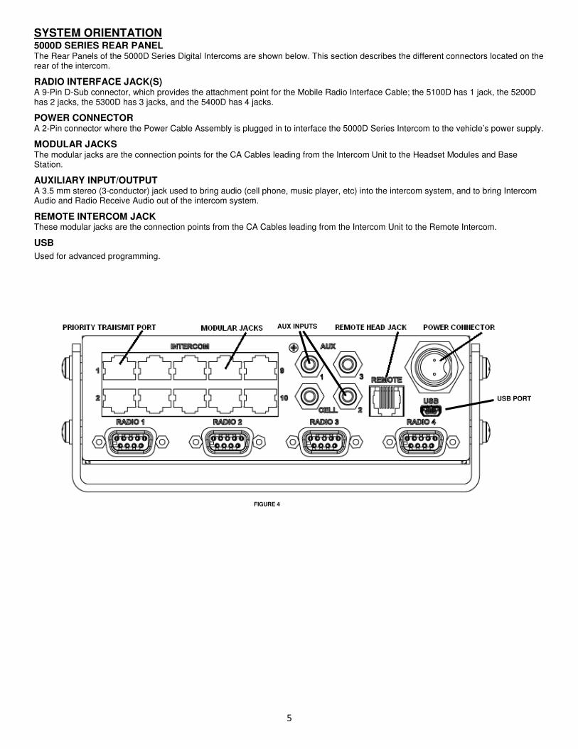
SYSTEM ORIENTATION 5000D SERIES REAR PANEL The Rear Panels of the 5000D Series Digital Intercoms are shown below. This section describes the different connectors located on the rear of the intercom.
RADIO INTERFACE JACK(S) A 9-Pin D-Sub connector, which provides the attachment point for the Mobile Radio Interface Cable; the 5100D has 1 jack, the 5200D has 2 jacks, the 5300D has 3 jacks, and the 5400D has 4 jacks.
POWER CONNECTOR A 2-Pin connector where the Power Cable Assembly is plugged in to interface the 5000D Series Intercom to the vehicle’s power supply.
MODULAR JACKS The modular jacks are the connection points for the CA Cables leading from the Intercom Unit to the Headset Modules and Base Station.
AUXILIARY INPUT/OUTPUT A 3.5 mm stereo (3-conductor) jack used to bring audio (cell phone, music player, etc) into the intercom system, and to bring Intercom Audio and Radio Receive Audio out of the intercom system.
REMOTE INTERCOM JACK These modular jacks are the connection points from the CA Cables leading from the Intercom Unit to the Remote Intercom.
USB
Used for advanced programming.
AUX INPUTS
USB PORT
FIGURE 4
6
PRE-INSTALLATION Before installing a Firecom 5000D Series Intercom System, it is very important to take time and plan the installation. This section will provide information to assist in planning the installation. You should read and understand all of the information contained in this section and the sections on System Orientation (page 2) and Installation (page 9) before installing the 5000D Series Intercom onto the apparatus.
IMPORTANT: Taking time to plan the installation BEFORE installing the 5000D Series Intercom System may prevent many installation errors which could result in improper system operation.
If you have any questions regarding the information contained in this section, contact your local Firecom Dealer for clarification BEFORE proceeding with the installation.
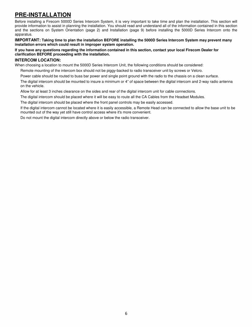
INTERCOM LOCATION: When choosing a location to mount the 5000D Series Intercom Unit, the following conditions should be considered:
Remote mounting of the intercom box should not be piggy-backed to radio transceiver unit by screws or Velcro.
Power cable should be routed to buss bar power and single point ground with the radio to the chassis on a clean surface.
The digital intercom should be mounted to insure a minimum or 4” of space between the digital intercom and 2-way radio antenna on the vehicle.
Allow for at least 3 inches clearance on the sides and rear of the digital intercom unit for cable connections.
The digital intercom should be placed where it will be easy to route all the CA Cables from the Headset Modules.
The digital intercom should be placed where the front panel controls may be easily accessed.
If the digital intercom cannot be located where it is easily accessible, a Remote Head can be connected to allow the base unit to be mounted out of the way yet still have control access where it's more convenient.
Do not mount the digital intercom directly above or below the radio transceiver.
7
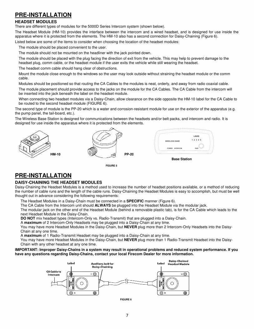
PRE-INSTALLATION HEADSET MODULES There are different types of modules for the 5000D Series Intercom system (shown below).
The Headset Module (HM-10) provides the interface between the intercom and a wired headset, and is designed for use inside the apparatus where it is protected from the elements. The HM-10 also has a second connection for Daisy-Chaining (Figure 6).
Listed below are some of the items to consider when choosing the location of the headset modules:
The module should be placed convenient to the user.
The module should not be mounted on the headliner with the jack pointed down.
The module should be placed with the plug facing the direction of exit from the vehicle. This may help to prevent damage to the headset plug, comm cable, or the headset module if the user exits the vehicle while still wearing the headset.
The headset comm cable should hang clear of obstructions.
Mount the module close enough to the windows so the user may look outside without straining the headset module or the comm cable.
Modules should be positioned so that routing the CA Cables to the modules is neat, orderly, and away from radio coaxial cable.
The module placement should provide access to the jacks on the module for the CA Cables. The CA Cable from the intercom will be inserted into the jack beneath the label on the headset module.
When connecting two headset modules via a Daisy-Chain, allow clearance on the side opposite the HM-10 label for the CA Cable to be routed to the second headset module (FIGURE 6).
The second type of module is the PP-20 which is a water and corrosion-resistant module for use on the exterior of the apparatus (e.g. the pump panel, the tail-board, etc.).
The Wireless Base Station is designed for communications between the headsets and/or belt packs, and intercom and radio. It is designed for use inside the apparatus where it is protected from the elements.
PRE-INSTALLATION DAISY-CHAINING THE HEADSET MODULES Daisy-Chaining the Headset Modules is a method used to increase the number of headset positions available, or a method of reducing the number of cable runs and the length of the cable runs. Daisy-Chaining the Headset Modules is easy to accomplish, but must be well thought out in advance considering the following requirements:
The Headset Modules in a Daisy-Chain must be connected in a SPECIFIC manner (Figure 6). The CA Cable from the Intercom unit should ALWAYS be plugged into the Headset Module via the modular jack. The modular jack on the other end of the Headset Module (behind a removable plastic tab), is for the CA Cable which leads to the next Headset Module in the Daisy-Chain. DO NOT mix headset types (Intercom-Only vs. Radio-Transmit) that are plugged into a Daisy-Chain. A maximum of 2 Intercom-Only Headsets may be plugged into a Daisy-Chain at any time. You may have more Headset Modules in the Daisy-Chain, but NEVER plug more than 2 Intercom-Only Headsets into the Daisy-Chain at any one time. A maximum of 1 Radio-Transmit Headset may be plugged into a Daisy-Chain at any time. You may have more Headset Modules in the Daisy-Chain, but NEVER plug more than 1 Radio-Transmit Headset into the Daisy-Chain with any other headset at any one time.
IMPORTANT: Improper Daisy-Chains in a system may result in operational problems and reduced system performance. If you have any questions regarding Daisy-Chains, contact your local Firecom Dealer for more information.
WIRELESS BASE
POWER INTERCOM PAIR
LINKS
1 2 3 4 5
HM-10 PP-20
Base Station
FIGURE 6
FIGURE 5
8
PRE-INSTALLATION ROUTING THE CA CABLES: CA cables are flat with six conductors, and may have RJ-12 Modular plugs on one or both cable ends used to make connections between the intercom unit and the HM-10’s, PP-20’s or Remote Intercom(s).
The path which you intend to run the CA Cables from the Intercom to the Headset Modules should also be planned BEFORE the installation. The items below are some of the items to consider when planning where to route the CA Cables.
Route the CA Cables away from hot surfaces (such as the vehicle exhaust system). Route the CA Cables away from any moving equipment on the vehicle. Route the CA Cables away from the antenna or the antenna cable.
DO NOT store excess cable. The length of each CA Cable should have no more than 10 inches of excess cable in each run for service loops (VERY IMPORTANT, especially in installations with a radio operating in the lower frequencies).
When routing the CA Cables through bulkheads or other sheet metal, use a rubber grommet in the hole to prevent damage to the cables.
REMOTE HEAD The main intercom can be remotely controlled by the Remote Head. This panel functions the same as the base unit front panel. Regardless of which button is pressed, both the main and remote units will respond and update at the same time. Power to the unit is supplied through the CA Cable from the Intercom. The Remote Head can be mounted either flush on the apparatus surface or with a special bracket.
INTERCOM CONNECTIONS: AUDIO MODULAR JACKS On the rear of the intercom, there are modular jacks under INTERCOM (Figure 13). These jacks are for connecting the CA Cables from the Headset Modules to the intercom. All of these modular jacks will provide intercom and radio communication to the headset positions.
REMOTE MODULAR JACKS On the rear of the intercom, there is 1 modular jack under REMOTE (Figure 13). This jack is for connecting CA Cables for the Remote Intercom(s). The CA Cables are all the same. Multiple Remote Intercoms can be installed by using an RJ12 splitter.
PRIORITY TRANSMIT It may be desirable for one member of the crew to have priority for transmitting on the radio. Any headset position plugged into this jack will have priority for radio transmit over all other headset positions. When the person in this position presses the PTT on the headset, ALL transmissions from any other headset position will be stopped and the person in the priority position will be able to transmit.
Priority Transmit Assignments:
5100D: Headset #1 has priority over Headset 2-6 5200D: Headset #1 has priority over Headsets 2-8, Headset #2 has priority over Headsets 3-8 5300D: Headset #1 has priority over Headset 2-10, Headset #2 has priority over Headsets 3-10, Headset #3 has priority over Headsets 4-10 5400D: Headset #1 has priority over Headset 2-10, Headset #2 has priority over Headsets 3-10, Headset #3 has priority over Headsets 4-10, Headset #4 has priority over Headsets 5-10
POWER CONNECTIONS The 5000D Series Intercom requires at least +12 volts DC nominal (with a negative ground) at 1.5 amps. This Intercom will accept DC voltage as high as 30 volts. The 5000D Series Intercom comes with a Power Cable Assembly and a 1.5 amp, in-line fuse. We suggest connecting the Intercom power and ground to the apparatus power buses.
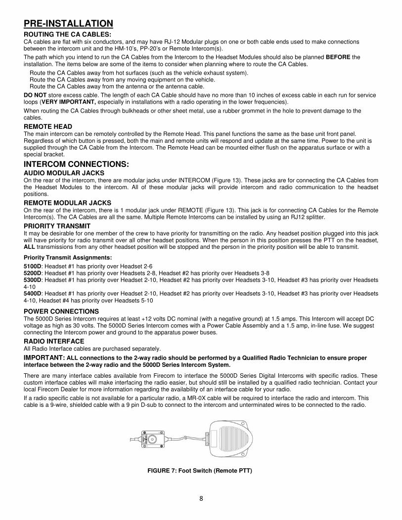
RADIO INTERFACE All Radio Interface cables are purchased separately.
IMPORTANT: ALL connections to the 2-way radio should be performed by a Qualified Radio Technician to ensure proper interface between the 2-way radio and the 5000D Series Intercom System.
There are many interface cables available from Firecom to interface the 5000D Series Digital Intercoms with specific radios. These custom interface cables will make interfacing the radio easier, but should still be installed by a qualified radio technician. Contact your local Firecom Dealer for more information regarding the availability of an interface cable for your radio.
If a radio specific cable is not available for a particular radio, a MR-0X cable will be required to interface the radio and intercom. This cable is a 9-wire, shielded cable with a 9 pin D-sub to connect to the intercom and unterminated wires to be connected to the radio.
FIGURE 7: Foot Switch (Remote PTT)
9
INSTALLATION
BEFORE INSTALLING the Firecom 5000D Series Intercoms, make sure you have read and understood the entire installation procedure. You should also read the sections on Pre-Installation (page 6) and System Orientation (pages 2 - 5). If any item in the Installation Procedure is not understood, or if you have any questions which are not addressed in this manual, contact your local Firecom Dealer for more information before you proceed with the installation.
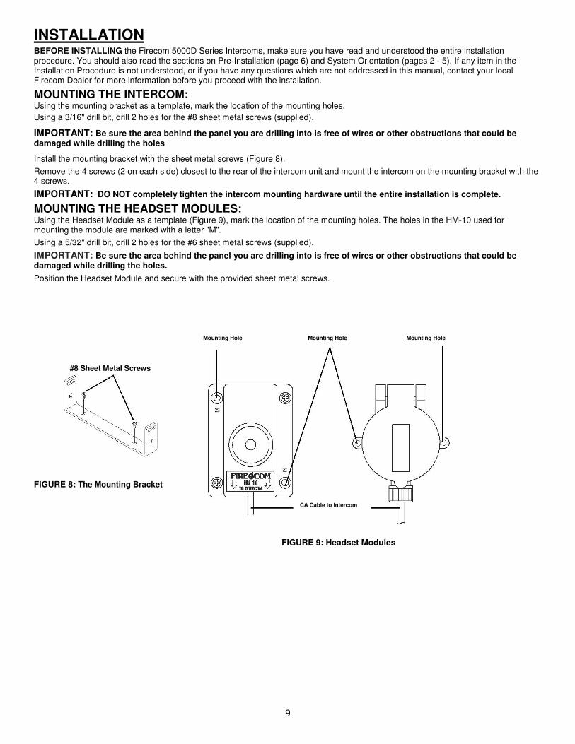
MOUNTING THE INTERCOM: Using the mounting bracket as a template, mark the location of the mounting holes.
Using a 3/16" drill bit, drill 2 holes for the #8 sheet metal screws (supplied).
IMPORTANT: Be sure the area behind the panel you are drilling into is free of wires or other obstructions that could be damaged while drilling the holes
Install the mounting bracket with the sheet metal screws (Figure 8).
Remove the 4 screws (2 on each side) closest to the rear of the intercom unit and mount the intercom on the mounting bracket with the 4 screws.
IMPORTANT: DO NOT completely tighten the intercom mounting hardware until the entire installation is complete.
MOUNTING THE HEADSET MODULES: Using the Headset Module as a template (Figure 9), mark the location of the mounting holes. The holes in the HM-10 used for mounting the module are marked with a letter ”M”.
Using a 5/32" drill bit, drill 2 holes for the #6 sheet metal screws (supplied).
IMPORTANT: Be sure the area behind the panel you are drilling into is free of wires or other obstructions that could be damaged while drilling the holes.
Position the Headset Module and secure with the provided sheet metal screws.
Mounting Hole Mounting Hole Mounting Hole
#8 Sheet Metal Screws
FIGURE 8: The Mounting Bracket
FIGURE 9: Headset Modules
CA Cable to Intercom
10
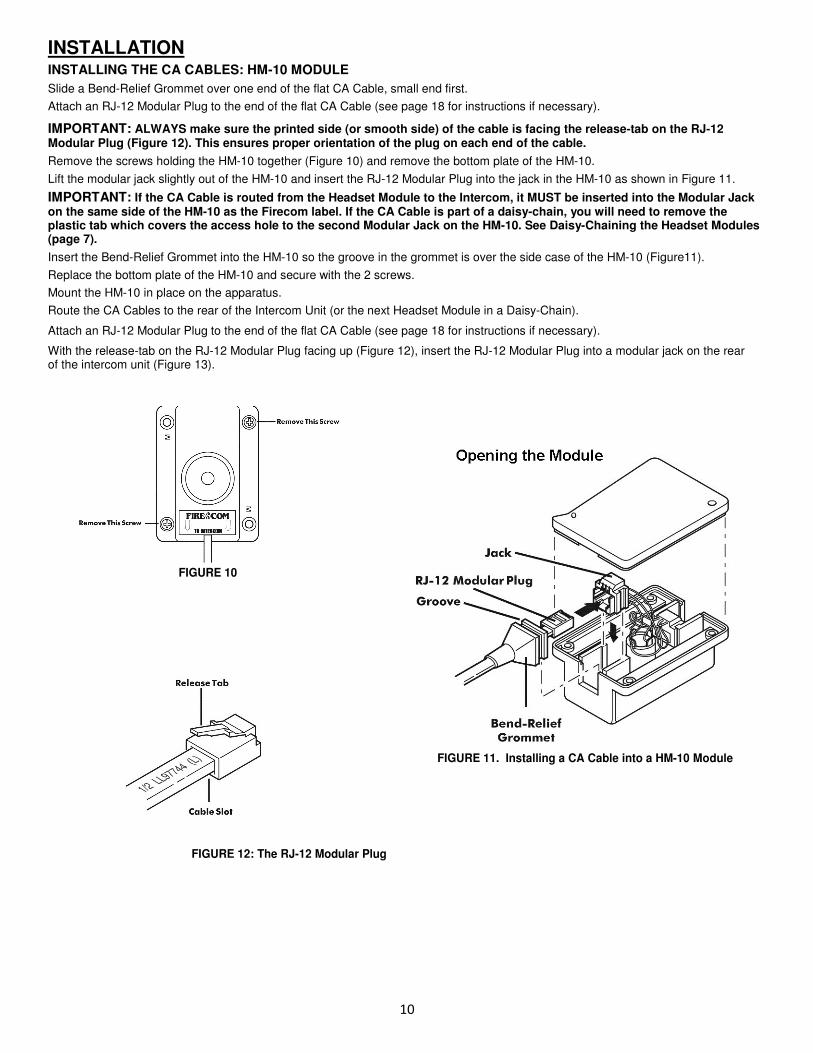
INSTALLATION INSTALLING THE CA CABLES: HM-10 MODULE
Slide a Bend-Relief Grommet over one end of the flat CA Cable, small end first.
Attach an RJ-12 Modular Plug to the end of the flat CA Cable (see page 18 for instructions if necessary).
IMPORTANT: ALWAYS make sure the printed side (or smooth side) of the cable is facing the release-tab on the RJ-12 Modular Plug (Figure 12). This ensures proper orientation of the plug on each end of the cable.
Remove the screws holding the HM-10 together (Figure 10) and remove the bottom plate of the HM-10.
Lift the modular jack slightly out of the HM-10 and insert the RJ-12 Modular Plug into the jack in the HM-10 as shown in Figure 11.
IMPORTANT: If the CA Cable is routed from the Headset Module to the Intercom, it MUST be inserted into the Modular Jack on the same side of the HM-10 as the Firecom label. If the CA Cable is part of a daisy-chain, you will need to remove the plastic tab which covers the access hole to the second Modular Jack on the HM-10. See Daisy-Chaining the Headset Modules (page 7).
Insert the Bend-Relief Grommet into the HM-10 so the groove in the grommet is over the side case of the HM-10 (Figure11).
Replace the bottom plate of the HM-10 and secure with the 2 screws.
Mount the HM-10 in place on the apparatus.
Route the CA Cables to the rear of the Intercom Unit (or the next Headset Module in a Daisy-Chain).
Attach an RJ-12 Modular Plug to the end of the flat CA Cable (see page 18 for instructions if necessary).
With the release-tab on the RJ-12 Modular Plug facing up (Figure 12), insert the RJ-12 Modular Plug into a modular jack on the rear of the intercom unit (Figure 13).
FIGURE 10
FIGURE 12: The RJ-12 Modular Plug
FIGURE 11. Installing a CA Cable into a HM-10 Module
11
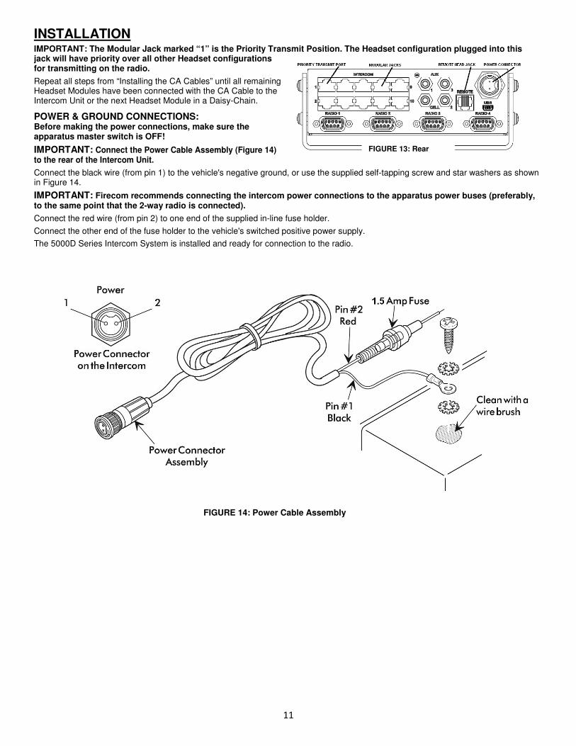
INSTALLATION IMPORTANT: The Modular Jack marked “1” is the Priority Transmit Position. The Headset configuration plugged into this jack will have priority over all other Headset configurations for transmitting on the radio.
Repeat all steps from “Installing the CA Cables” until all remaining Headset Modules have been connected with the CA Cable to the Intercom Unit or the next Headset Module in a Daisy-Chain.
POWER & GROUND CONNECTIONS: Before making the power connections, make sure the apparatus master switch is OFF!
IMPORTANT: Connect the Power Cable Assembly (Figure 14) to the rear of the Intercom Unit.
Connect the black wire (from pin 1) to the vehicle's negative ground, or use the supplied self-tapping screw and star washers as shown in Figure 14.
IMPORTANT: Firecom recommends connecting the intercom power connections to the apparatus power buses (preferably, to the same point that the 2-way radio is connected).
Connect the red wire (from pin 2) to one end of the supplied in-line fuse holder.
Connect the other end of the fuse holder to the vehicle's switched positive power supply.
The 5000D Series Intercom System is installed and ready for connection to the radio.
FIGURE 14: Power Cable Assembly
FIGURE 13: Rear
12
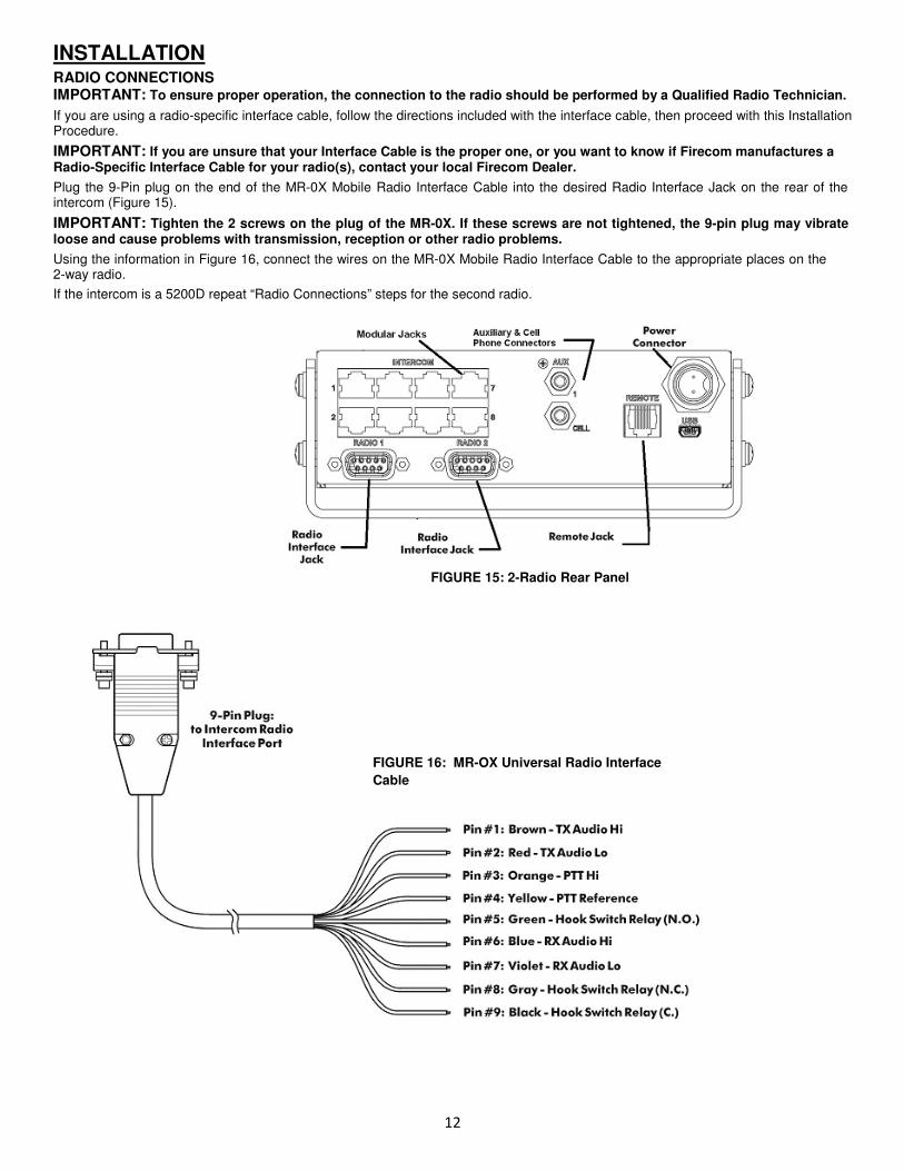
INSTALLATION RADIO CONNECTIONS IMPORTANT: To ensure proper operation, the connection to the radio should be performed by a Qualified Radio Technician.
If you are using a radio-specific interface cable, follow the directions included with the interface cable, then proceed with this Installation Procedure.
IMPORTANT: If you are unsure that your Interface Cable is the proper one, or you want to know if Firecom manufactures a Radio-Specific Interface Cable for your radio(s), contact your local Firecom Dealer.
Plug the 9-Pin plug on the end of the MR-0X Mobile Radio Interface Cable into the desired Radio Interface Jack on the rear of the intercom (Figure 15).
IMPORTANT: Tighten the 2 screws on the plug of the MR-0X. If these screws are not tightened, the 9-pin plug may vibrate loose and cause problems with transmission, reception or other radio problems.
Using the information in Figure 16, connect the wires on the MR-0X Mobile Radio Interface Cable to the appropriate places on the 2-way radio.
If the intercom is a 5200D repeat “Radio Connections” steps for the second radio.
FIGURE 15: 2-Radio Rear Panel
FIGURE 16: MR-OX Universal Radio Interface
Cable
13
INSTALLATION
AUXILIARY INPUT & OUTPUT
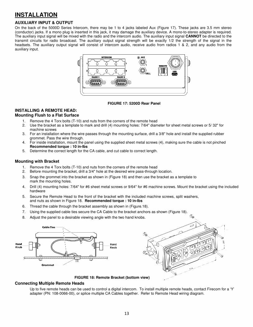
On the back of the 5000D Series Intercom, there may be 1 to 4 jacks labeled Aux (Figure 17). These jacks are 3.5 mm stereo (conductor) jacks. If a mono plug is inserted in this jack, it may damage the auxiliary device. A mono-to-stereo adapter is required. The auxiliary input signal will be mixed with the radio and the intercom audio. The auxiliary input signal CANNOT be directed to the transmit circuits for radio broadcast. The auxiliary output signal strength will be exactly 1/2 the strength of the signal in the headsets. The auxiliary output signal will consist of intercom audio, receive audio from radios 1 & 2, and any audio from the auxiliary input.
FIGURE 17: 5200D Rear Panel
INSTALLING A REMOTE HEAD: Mounting Flush to a Flat Surface
1. Remove the 4 Torx bolts (T-10) and nuts from the corners of the remote head 2. Use the bracket as a template to mark and drill (4) mounting holes: 7/64" diameter for sheet metal screws or 5/ 32" for
machine screws 3. For an installation where the wire passes through the mounting surface, drill a 3/8" hole and install the supplied rubber
grommet. Pass the wire through. 4. For inside installation, mount the panel using the supplied sheet metal screws (4), making sure the cable is not pinched
Recommended torque : 10 in-lbs 5. Determine the correct length for the CA cable, and cut cable to correct length.
Mounting with Bracket
1. Remove the 4 Torx bolts (T-10) and nuts from the corners of the remote head 2. Before mounting the bracket, drill a 3/4" hole at the desired wire pass-through location.
3. Snap the grommet into the bracket as shown in (Figure 18) and then use the bracket as a template to mark the mounting holes.
4. Drill (4) mounting holes: 7/64" for #6 sheet metal screws or 9/64" for #6 machine screws. Mount the bracket using the included hardware
5. Secure the Remote Head to the front of the bracket with the included machine screws, split washers, and nuts as shown in Figure 18. Recommended torque : 10 in-lbs
6. Thread the cable through the bracket assembly as shown in (Figure.18).
7. Using the supplied cable ties secure the CA Cable to the bracket anchors as shown (Figure 18).
8. Adjust the panel to a desirable viewing angle with the two hand knobs.
FIGURE 18: Remote Bracket (bottom view)
Connecting Multiple Remote Heads
Up to five remote heads can be used to control a digital intercom. To install multiple remote heads, contact Firecom for a ‘Y’ adapter (PN: 108-0066-00), or splice multiple CA Cables together. Refer to Remote Head wiring diagram.
14
SYSTEM TEST This procedure tests all functions of the 5000D Series Intercom System and is used to test the system for proper operation after installation. In the event of a system failure, it may be used to identify exact symptoms before troubleshooting a problem, and to test the system after repair work has been performed.
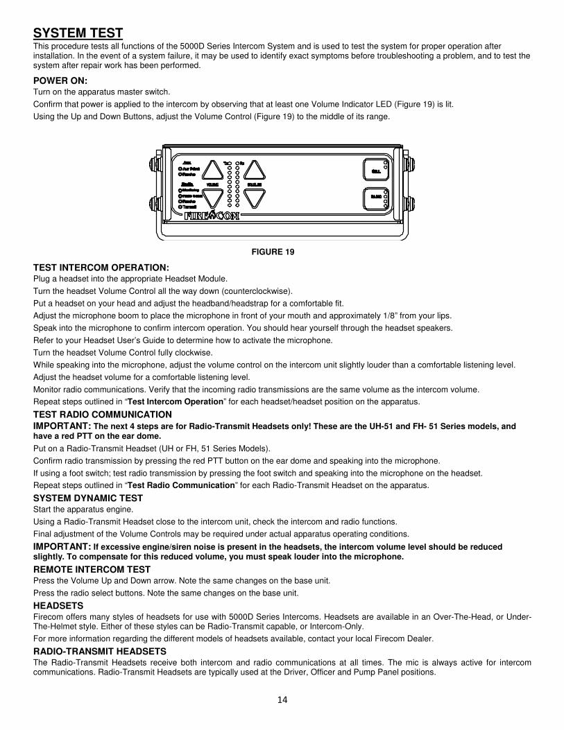
POWER ON: Turn on the apparatus master switch.
Confirm that power is applied to the intercom by observing that at least one Volume Indicator LED (Figure 19) is lit.
Using the Up and Down Buttons, adjust the Volume Control (Figure 19) to the middle of its range.
FIGURE 19
TEST INTERCOM OPERATION: Plug a headset into the appropriate Headset Module.
Turn the headset Volume Control all the way down (counterclockwise).
Put a headset on your head and adjust the headband/headstrap for a comfortable fit.
Adjust the microphone boom to place the microphone in front of your mouth and approximately 1/8” from your lips.
Speak into the microphone to confirm intercom operation. You should hear yourself through the headset speakers.
Refer to your Headset User’s Guide to determine how to activate the microphone.
Turn the headset Volume Control fully clockwise.
While speaking into the microphone, adjust the volume control on the intercom unit slightly louder than a comfortable listening level.
Adjust the headset volume for a comfortable listening level.
Monitor radio communications. Verify that the incoming radio transmissions are the same volume as the intercom volume.
Repeat steps outlined in “Test Intercom Operation” for each headset/headset position on the apparatus.
TEST RADIO COMMUNICATION IMPORTANT: The next 4 steps are for Radio-Transmit Headsets only! These are the UH-51 and FH- 51 Series models, and have a red PTT on the ear dome.
Put on a Radio-Transmit Headset (UH or FH, 51 Series Models).
Confirm radio transmission by pressing the red PTT button on the ear dome and speaking into the microphone.
If using a foot switch; test radio transmission by pressing the foot switch and speaking into the microphone on the headset.
Repeat steps outlined in “Test Radio Communication” for each Radio-Transmit Headset on the apparatus.
SYSTEM DYNAMIC TEST Start the apparatus engine.
Using a Radio-Transmit Headset close to the intercom unit, check the intercom and radio functions.
Final adjustment of the Volume Controls may be required under actual apparatus operating conditions.
IMPORTANT: If excessive engine/siren noise is present in the headsets, the intercom volume level should be reduced slightly. To compensate for this reduced volume, you must speak louder into the microphone.
REMOTE INTERCOM TEST Press the Volume Up and Down arrow. Note the same changes on the base unit.
Press the radio select buttons. Note the same changes on the base unit.
HEADSETS Firecom offers many styles of headsets for use with 5000D Series Intercoms. Headsets are available in an Over-The-Head, or Under-The-Helmet style. Either of these styles can be Radio-Transmit capable, or Intercom-Only.
For more information regarding the different models of headsets available, contact your local Firecom Dealer.
RADIO-TRANSMIT HEADSETS The Radio-Transmit Headsets receive both intercom and radio communications at all times. The mic is always active for intercom communications. Radio-Transmit Headsets are typically used at the Driver, Officer and Pump Panel positions.
15
INTERCOM OPERATION VOLUME CONTROLS (ALL MODELS):
VOLUME INDICATOR The Volume Indicator is a vertical row of 10 colored LED’s. Minimum volume is indicated by only the bottom yellow indicator being lit. Maximum volume is indicated by all 10 LED’s being lit. Master headset volume is set with the front face volume pad
IMPORTANT: When power is turned off to the intercom, the intercom and Remote Intercoms remember the last volume setting and will return to that volume level when power is turned on again.
VOLUME UP BUTTON (ALL MODELS) Pressing this button once increases the intercom volume by one step. After pressing the button three times one more LED in the Volume Indicator lights. Once maximum volume has been reached (all LED's in the Volume Indicator are lit), pressing the Volume Up Button will have no effect.
VOLUME DOWN BUTTON (ALL MODELS) Pressing this button once decreases the intercom volume by one step. After pressing the button three times, one less LED in the Volume Indicator lights. Once minimum volume has been reached (only the bottom LED in the Volume Indicator is lit), pressing the Volume Down Button will have no effect.
The minimum volume level is not zero volume. It is NOT possible to turn the intercom audio off using the Volume Control Buttons.
The Volume Controls on the 5000D Series Digital Intercoms adjust the volume of INTERCOM COMMUNICATION ONLY! The Volume Controls DO NOT adjust the volume of the Receive Audio from the radio(s). To adjust the volume of the Receive Audio, adjust the Receive Audio Adjustment (page 16) or the radio's volume control.
INTERCOM ADJUSTMENTS AND OPERATIONS: For the Radio, Aux, and Cell connections to the intercom the user can adjust input gain and output gain to allow interfacing the intercom to other equipment.
It is important to set your device gain levels appropriately for your connected equipment. • An input gain that is too low results in insufficient volume level.
• An output gain that is too low causes insufficient volume level in your end device.
• An output gain that is too high results in audio distortion caused by clipping or squealing in your output device.
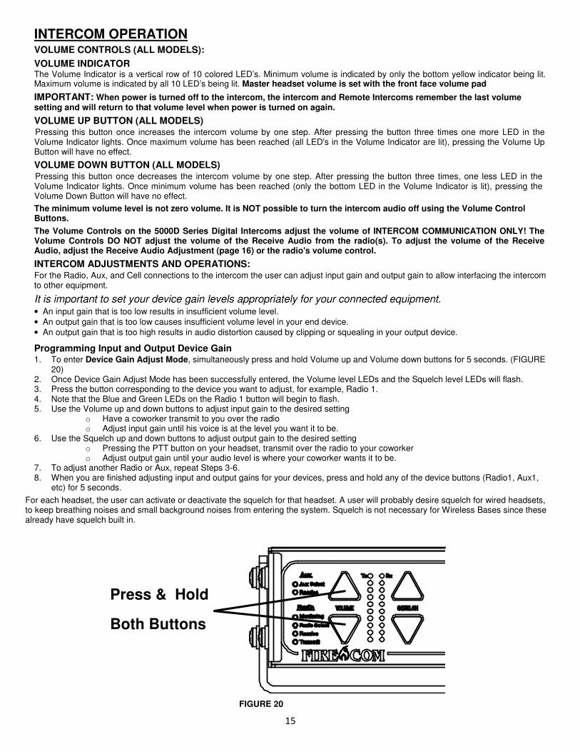
Programming Input and Output Device Gain 1. To enter Device Gain Adjust Mode, simultaneously press and hold Volume up and Volume down buttons for 5 seconds. (FIGURE
20) 2. Once Device Gain Adjust Mode has been successfully entered, the Volume level LEDs and the Squelch level LEDs will flash. 3. Press the button corresponding to the device you want to adjust, for example, Radio 1. 4. Note that the Blue and Green LEDs on the Radio 1 button will begin to flash. 5. Use the Volume up and down buttons to adjust input gain to the desired setting
o Have a coworker transmit to you over the radio o Adjust input gain until his voice is at the level you want it to be.
6. Use the Squelch up and down buttons to adjust output gain to the desired setting o Pressing the PTT button on your headset, transmit over the radio to your coworker o Adjust output gain until your audio level is where your coworker wants it to be.
7. To adjust another Radio or Aux, repeat Steps 3-6. 8. When you are finished adjusting input and output gains for your devices, press and hold any of the device buttons (Radio1, Aux1,
etc) for 5 seconds.
For each headset, the user can activate or deactivate the squelch for that headset. A user will probably desire squelch for wired headsets, to keep breathing noises and small background noises from entering the system. Squelch is not necessary for Wireless Bases since these already have squelch built in.
FIGURE 20
Press & Hold
Both Buttons
16
Squelch The Squelch is a system wide squelch adjust. All headsets that have squelch enabled will respond to changes in the squelch level.
To change the Squelch level, press the Squelch up or Squelch down buttons to increase or decrease the squelch level. Higher squelch levels are needed for higher noise environments.
Tech Note:
For wireless base stations, it is suggested that you disable squelch for the headset port which you have plugged your wireless base into.
Headset Squelch Enable/Disable
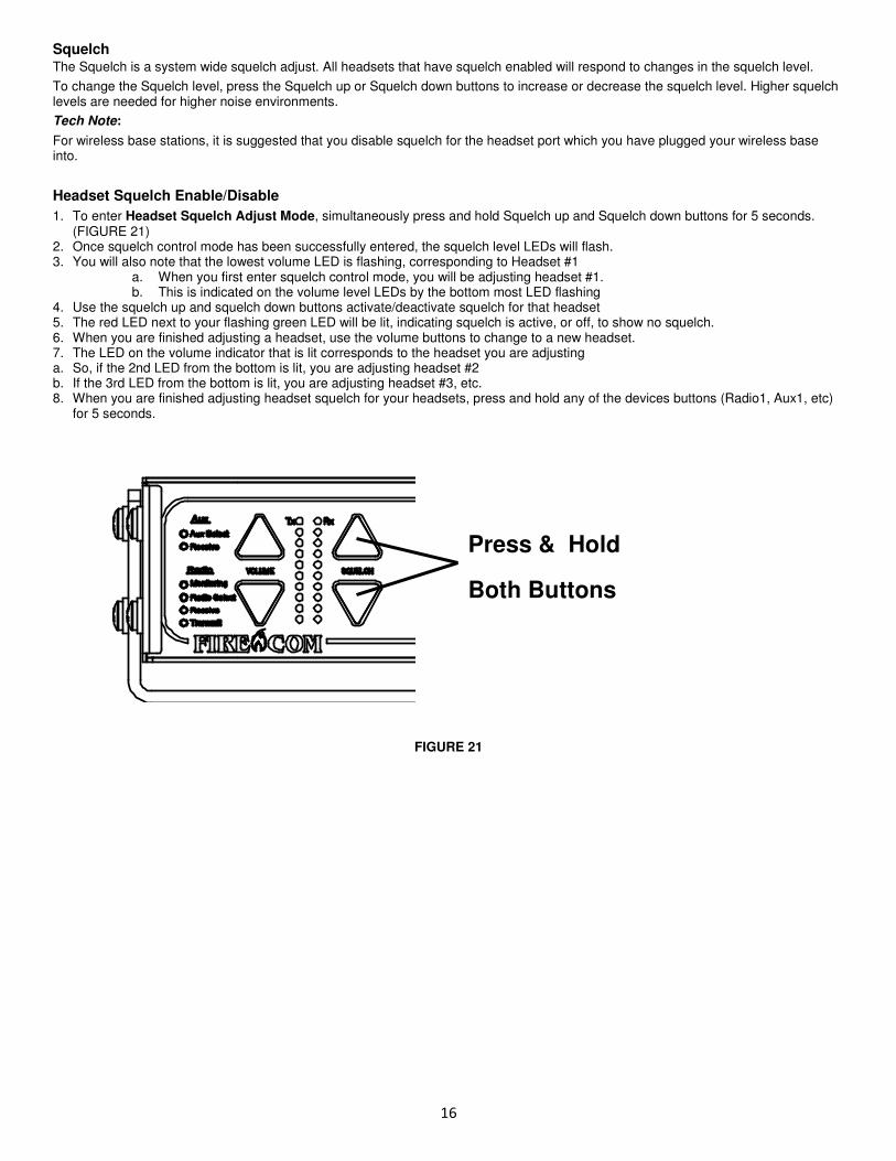
1. To enter Headset Squelch Adjust Mode, simultaneously press and hold Squelch up and Squelch down buttons for 5 seconds. (FIGURE 21)
2. Once squelch control mode has been successfully entered, the squelch level LEDs will flash. 3. You will also note that the lowest volume LED is flashing, corresponding to Headset #1
a. When you first enter squelch control mode, you will be adjusting headset #1. b. This is indicated on the volume level LEDs by the bottom most LED flashing
4. Use the squelch up and squelch down buttons activate/deactivate squelch for that headset 5. The red LED next to your flashing green LED will be lit, indicating squelch is active, or off, to show no squelch. 6. When you are finished adjusting a headset, use the volume buttons to change to a new headset. 7. The LED on the volume indicator that is lit corresponds to the headset you are adjusting a. So, if the 2nd LED from the bottom is lit, you are adjusting headset #2 b. If the 3rd LED from the bottom is lit, you are adjusting headset #3, etc. 8. When you are finished adjusting headset squelch for your headsets, press and hold any of the devices buttons (Radio1, Aux1, etc)
for 5 seconds.
FIGURE 21
Press & Hold
Both Buttons
17
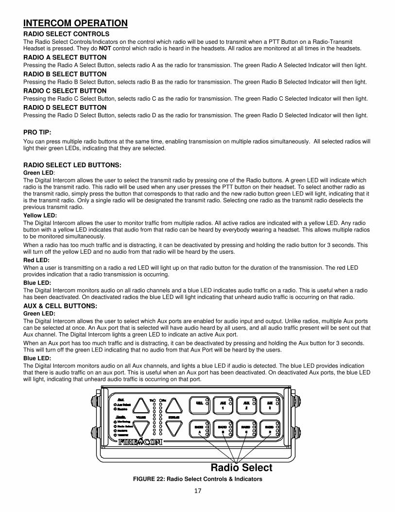
INTERCOM OPERATION RADIO SELECT CONTROLS The Radio Select Controls/Indicators on the control which radio will be used to transmit when a PTT Button on a Radio-Transmit Headset is pressed. They do NOT control which radio is heard in the headsets. All radios are monitored at all times in the headsets.
RADIO A SELECT BUTTON Pressing the Radio A Select Button, selects radio A as the radio for transmission. The green Radio A Selected Indicator will then light.
RADIO B SELECT BUTTON Pressing the Radio B Select Button, selects radio B as the radio for transmission. The green Radio B Selected Indicator will then light.
RADIO C SELECT BUTTON Pressing the Radio C Select Button, selects radio C as the radio for transmission. The green Radio C Selected Indicator will then light.
RADIO D SELECT BUTTON Pressing the Radio D Select Button, selects radio D as the radio for transmission. The green Radio D Selected Indicator will then light.
PRO TIP:
You can press multiple radio buttons at the same time, enabling transmission on multiple radios simultaneously. All selected radios will light their green LEDs, indicating that they are selected.
RADIO SELECT LED BUTTONS: Green LED:
The Digital Intercom allows the user to select the transmit radio by pressing one of the Radio buttons. A green LED will indicate which radio is the transmit radio. This radio will be used when any user presses the PTT button on their headset. To select another radio as the transmit radio, simply press the button that corresponds to that radio and the new radio button green LED will light, indicating that it is the transmit radio. Only a single radio will be designated the transmit radio. Selecting one radio as the transmit radio deselects the previous transmit radio.
Yellow LED:
The Digital Intercom allows the user to monitor traffic from multiple radios. All active radios are indicated with a yellow LED. Any radio button with a yellow LED indicates that audio from that radio can be heard by everybody wearing a headset. This allows multiple radios to be monitored simultaneously.
When a radio has too much traffic and is distracting, it can be deactivated by pressing and holding the radio button for 3 seconds. This will turn off the yellow LED and no audio from that radio will be heard by the users.
Red LED:
When a user is transmitting on a radio a red LED will light up on that radio button for the duration of the transmission. The red LED provides indication that a radio transmission is occurring.
Blue LED:
The Digital Intercom monitors audio on all radio channels and a blue LED indicates audio traffic on a radio. This is useful when a radio has been deactivated. On deactivated radios the blue LED will light indicating that unheard audio traffic is occurring on that radio.
AUX & CELL BUTTONS: Green LED:
The Digital Intercom allows the user to select which Aux ports are enabled for audio input and output. Unlike radios, multiple Aux ports can be selected at once. An Aux port that is selected will have audio heard by all users, and all audio traffic present will be sent out that Aux channel. The Digital Intercom lights a green LED to indicate an active Aux port.
When an Aux port has too much traffic and is distracting, it can be deactivated by pressing and holding the Aux button for 3 seconds. This will turn off the green LED indicating that no audio from that Aux Port will be heard by the users.
Blue LED:
The Digital Intercom monitors audio on all Aux channels, and lights a blue LED if audio is detected. The blue LED provides indication that there is audio traffic on an aux port. This is useful when an Aux port has been deactivated. On deactivated Aux ports, the blue LED will light, indicating that unheard audio traffic is occurring on that port.
FIGURE 22: Radio Select Controls & Indicators
Radio Select

18
MODULAR PLUG INSTALLATION
This section describes the installation of the RJ-12 Modular Plugs onto the flat CA Cable.
1. Using the cutter blade on the crimping tool (labeled A in Figure 23), cut the flat CA Cable so the cut is clean and 90 degrees to the sides of the cable.
2. Fully insert one end of the CA Cable between the stripping blades (labeled C in Figure 23) until the end of the cable hits the stop (labeled B in Figure 23).
FIGURE 23: RJ-12 Modular Plug Crimping Tool FIGURE 24: Stripped CA Cable
3. Squeeze the handles of the crimping tool together until the tool bottoms out. 4. While holding the handles together, pull the cable out of the tool. 5. The stripped insulation should expose approximately 3/16” of wire (Figure 24). 6. Push a RJ-12 Modular Plug into the plug holder on the crimping tool (labeled D in 23) until the release tab on the plug locks into
position. 7. Holding the cable so that the printed side (or smooth side) of the cable is toward the release-tab on the plug, push the cable into
the plug as far as it will go. ALWAYS make sure the printed side (or smooth side) of the cable is facing the release-tab on the RJ-12 Modular Plug (Figure 25). This ensures proper orientation of the plug on each end of the cable.
8. Squeeze the tool handles COMPLETELY together. You may feel the crimper finish punching the contacts through the insulation on the wires.
9. Let the handles spring open.
10. Push down on the release-tab on the RJ-12 Modular Plug (Figure 25) and remove the RJ-12 Modular Plug from the crimping tool.
11. Inspect the plug to ensure that the cable is held securely in place.
12. Repeat this procedure as necessary to install a RJ-12 Modular Plug on each end of each CA Cable.
FIGURE 25: RJ-12 Modular Plug
19
TROUBLESHOOTING The Firecom 5000D Series Intercoms, when installed properly and adjusted according to specifications, will perform reliably and offer you the finest in hearing protection and enhanced communication. However, as with any electronic equipment, occasionally a malfunction may occur.
In the following sections, you will find information that will help familiarize you with the intercom system and aid in the troubleshooting process.
If the symptoms you are experiencing are not covered in this manual, or if you are having difficulty troubleshooting your system, contact your local Firecom Dealer for assistance.
IF THE SYSTEM DOES NOT OPERATE AS EXPECTED, CHECK THE FOLLOWING ITEMS FIRST: - Check that the apparatus master switch is on.
- Check the fuse or circuit breaker.
- Check system wiring and interconnections.
- Check the orientation of all RJ-12 Modular Connectors on both ends of each CA Cable. See Modular Plug Installation (page 18).
- Check that the headsets are plugged in all the way.
- Check intercom and headset control settings.
- Check for corrosion on headset plugs.
- Check all intercom ports for bent or stuck pins that can be straightened.
If these steps do not correct the problem, review the Advanced Troubleshooting procedures on pages 21-22. ALTERNATOR WHINE & OTHER DISTRACTING NOISES Because of the level of ambient noise present with the apparatus motor running, alternator whine and other noises may not be noticed in the communications systems until an intercom is added. A noisy system will always be more apparent, once an intercom is installed.
COMMON CAUSES OF NOISE ON THE COMMUNICATION CIRCUIT Improper installation
Intercom adjusted improperly
Radio Interface not connected properly
Intercom power connections dirty, loose or connected to the wrong location
Battery terminals corroded
A faulty alternator
Generally, the problem is not caused by the alternator, but is usually the result of a difference in potential between the apparatus radio signal ground and intercom signal ground. Additional sources may also exist in the apparatus electrical system.
TO REDUCE OR ELIMINATE ALTERNATOR WHINE Connect the apparatus radio to the cleanest power source: a source without motors (e.g. heaters, windshield wipers, etc.), sirens, strobes or flashers.
Use the same precautions when connecting the intercom power.
Ensure that the power and ground connections for the radio and the intercom are clean and tight.
Ensure that the power and ground wires for the radio and the intercom are no smaller in diameter than 18 AWG.
Keep all battery connections clean and free from dirt and corrosion.
Use separate noise filters on radio and/or intercom power as needed
20
TROUBLESHOOTING TROUBLESHOOTING A HEADSET CONFIGURATION This procedure will help determine if a problem exists in a particular headset configuration, and which component in the headset configuration is faulty.
Examine the headset’s label to determine if the headset is an Intercom-Only Headset or a Radio-Transmit Headset.
If the headset is a 51 Series FH or UH model, it is a Radio-Transmit headset. The speakers should always be active. The mic should always be active for intercom communication and pressing the Red PTT button on the ear dome will key the radio for radio transmission.
If the headset is a 52 Series FH or UH model, it is an Intercom-Only Headset. The speakers should always be active. The mic should be active for intercom communication only when the Black PTT button on the ear dome is pressed. The headset should never cause the radio to key.
If the headset is a 54 Series FH or UH model, it is an Intercom-Only Headset. The speakers should always be active. Pressing the Yellow PTT on the ear dome will activate the mic for intercom communication. The mic will remain active until the Yellow PTT is pressed again.
Plug the headset into another good headset configuration.
If the headset fails to perform properly in the new location, the headset is faulty. Contact Firecom Service for a Return Material Authorization (RMA) Number. to return the headset for repair.
Unplug the CA Cable from the intercom unit and exchange intercom ports with a known good headset configuration.
If the headset configuration works properly, check the intercom port for bent or stuck pins which can be straightened.
If the headset fails to perform properly, the headset configuration has a faulty component and you should continue troubleshooting the headset configuration.
Check the HM-10 by exchanging it with a known good one.
If the new HM-10 works, check the RJ-12 Modular Jack of the faulty HM-10 for bent or stuck pins. If the pins look good and the HM-10 fails to perform properly, it will need to be replaced.
Install new RJ-12 Modular Plugs on BOTH ends of the CA Cable (page 23).
Replace the CA Cable.
21
ADVANCED TROUBLE-SHOOTING This section is designed for use by a QUALIFIED RADIO TECHNICIAN only! The headset was working properly, but has now failed. Make sure you read and understand the entire procedure before attempting any of the troubleshooting steps in this section.
If there are questions regarding this information, contact your local Firecom Dealer for more information before proceeding with the troubleshooting steps.
The System Test on page 14 is also a helpful tool in isolating and determining the actual symptoms of the problem.
THERE IS NO SOUND IN THE HEADSET FROM EITHER THE INTERCOM OR THE RADIO
Check the headset Volume Control. Make sure it is not turned all the way down.
Check the headset configuration for faulty connections or components. See Troubleshooting a Headset configuration (page 20).
Verify that some of the Volume Indicator LEDs on the front panel of the intercom are lit, indicating that the intercom is powered on.
Measure the voltage between pins 1 & 2 on the Power Cable. There should be at least 12 volts DC present, and not more than 30 volts DC.
Check the wiring to the intercom and any fuses or circuit breakers in the power circuits to the intercom and correct any faults.
If there is sufficient power to the intercom, and it doesn’t work, the Intercom Unit is faulty. Contact Firecom Service for a Return Material Authorization (RMA) Number to return the Intercom Unit for repair.
THERE IS SOUND IN THE HEADSET FROM THE INTERCOM, BUT NOT FROM THE RADIO (Perform one or more of the following as needed.) Check the radio volume. Make sure it is not turned all the way down.
If there is no audio from the radio’s speaker:
Disconnect the Radio Interface Cable from the radio. If there is audio from the radio’s speaker, the Radio Interface Cable is faulty.
If there is still no audio from the radio’s speaker, the radio is faulty.
Disconnect the Radio Interface Cable from the back of the intercom unit. If there is audio from the radio’s speaker, the Intercom Unit is faulty. Contact Firecom Service for a Return Material Authorization (RMA) Number to return the Intercom Unit for repair.
If there is audio from the radio’s speaker, check the connections to pins 6 & 7 on the Radio Interface Port on the back of the intercom unit.
Verify that Receive Audio is present by listening to the radio’s speaker.
Try swapping the intercom unit with a known good one (if one is available). If the problem persists, the problem is in the Radio or the Mobile Radio Interface wiring.
If no fault can be found, then the fault must lie in the Intercom Unit. Contact Firecom Service for a Return Material Authorization (RMA) Number to return the Intercom Unit for repair.
22
ADVANCED TROUBLE-SHOOTING THERE IS SOUND IN THE HEADSET FROM THE RADIO, BUT NOT FROM THE INTERCOM
Check the headset configuration for faulty connections or components. See Troubleshooting a Headset configuration (page 20).
The Intercom Unit is faulty. Contact Firecom for a Return Material Authorization (RMA) Number to return the Intercom Unit for repair.
THERE IS SOUND IN ONLY ONE EAR
Check to see if the headset is a model UH-51S headset. The UH-51S has one slotted ear dome without a speaker in it. This is normal operation for a UH-51S.
The headset is faulty. Contact Firecom for a Return Material Authorization (RMA) Number to return the headset for repair.
YOU CAN HEAR OTHERS ON THE INTERCOM, BUT THEY CANNOT HEAR YOU
If the headset is an Intercom-Only Headset with a Black PTT, be sure that the PTT button is fully depressed when trying to talk on the intercom.
If the headset is an Intercom-Only Headset with a Yellow PTT, press and release the PTT and test again.
Check the headset configuration for faulty connections or components. See Troubleshooting a Headset configuration (page 20).
The headset is faulty. Contact Firecom for a Return Material Authorization (RMA) Number to return the headset for repair.
YOU CAN'T HEAR OTHERS ON THE INTERCOM, BUT THEY CAN HEAR YOU
Check the headset configuration for faulty connections or components. See Troubleshooting a Headset configuration (page 20).
The Intercom Unit is faulty. Contact Firecom for a Return Material Authorization (RMA) Number to return the Intercom unit for repair.
THERE IS A LOUD SQUEAL IN THE INTERCOM SYSTEM WHEN THE INTERCOM VOLUME IS TURNED UP
Check for an open mic too near the speakers of a headset. Feedback problems are often fixed by turning the intercom volume down, moving the mic away from the headset speakers, or unplugging a headset when not in use.
If the problem persists, unplug the headset configurations one at a time from the rear of the Intercom Unit until the squeal stops.
Check the headset configuration for faulty connections or components. See Troubleshooting a Headset configuration (page 20).
Check the radio programming for “Mic Mute Checked”.
THE RADIO RECEIVE AUDIO IS WEAK
Check the setting of the radio’s volume control. The radio’s volume should be set at the normal volume for use with no intercom system present.
Verify proper connection to pins 6 & 7 on the Radio Interface Cable.
Try swapping the Intercom Unit with a known good one (if one is available). If the problem persists, the problem is in the radio or the Mobile Radio Interface wiring.
If no fault can be found, then the fault must lie in the Intercom Unit. Contact Firecom for a Return Materials Authorization (RMA) Number to return the Intercom Unit for repair.
THE RADIO KEYS BUT HAS NO TRANSMIT AUDIO (CARRIER BUT NO AUDIO)
Check the affected headset configuration for faulty connections or components. See Troubleshooting a Headset configuration (page 20).
Verify connection of pins 1 & 2 on the Radio Interface Cable and the Radio Interface Port.
Try swapping the Intercom Unit with a known good one (if one is available). If the problem persists, the problem is in the Mobile Radio Interface wiring.
If no fault can be found, then the fault must lie in the Intercom Unit. Contact Firecom for a Return Materials Authorization (RMA) Number to return the Intercom Unit for repair.
THERE IS A SQUEAL IN TRANSMIT AUDIO:
Check radio programming.
Check the Transmit Audio Gain Setting.
23
WIRING DIAGRAM & SCHEMATICS
24
WIRING DIAGRAM & SCHEMATICS
25
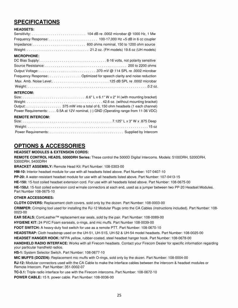
SPECIFICATIONS
HEADSETS:
Sensitivity: . . . . . . . . . . . . . . . . . . . . . . . . . . . . 104 dB re .0002 microbar @ 1000 Hz, 1 Mw
Frequency Response: . . . . . . . . . . . . . . . . . . . . . . . . . 100-17,000 Hz +5 dB in 6 cc coupler
Impedance: . . . . . . . . . . . . . . . . . . . . . . . . . . . 600 ohms nominal, 150 to 1200 ohm source
Weight: . . . . . . . . . . . . . . . . . . . . . . . . . . . . . . . . 21.2 oz. (FH models) 19.6 oz (UH models)
MICROPHONE:
DC Bias Supply: . . . . . . . . . . . . . . . . . . . . . . . . . . . . . . . . . . 8-16 volts, not polarity sensitive
Source Resistance: . . . . . . . . . . . . . . . . . . . . . . . . . . . . . . . . . . . . . . . . . . 200 to 2200 ohms
Output Voltage: . . . . . . . . . . . . . . . . . . . . . . . . . . . . . .370 mV @ 114 SPL re .0002 microbar
Frequency Response:. . . . . . . . . . . . . . . . . Optimized for speech clarity and noise reduction
Max. Amb. Noise Level:. . . . . . . . . . . . . . . . . . . . . . . . . . . . . .125 dB SPL re .0002 microbar
Weight: . . . . . . . . . . . . . . . . . . . . . . . . . . . . . . . . . . . . . . . . . . . . . . . . . . . . . . . . . . . . . .0.2 oz.
INTERCOM:
Size: . . . . . . . . . . . . . . . . . . . . . . . . . . . . . . . . .6.6" L x 6.1" W x 2" H (with mounting bracket)
Weight: . . . . . . . . . . . . . . . . . . . . . . . . . . . . . . . . . . . . . . . 42.6 oz. (without mounting bracket)
Output: . . . . . . . . . . . . . . . . . . 375 mW into a total of 6, 150 ohm headsets (1 each channel) Power Requirements: . . . . 0.5A at 12V nominal, (-) GND (Operating range from 11-36 VDC)
REMOTE INTERCOM: Size: . . . . . . . . . . . . . . . . . . . . . . . . . . . . . . . . . . . . . . . . . . . . . . 7.125" L x 3" W x .875 Deep
Weight: . . . . . . . . . . . . . . . . . . . . . . . . . . . . . . . . . . . . . . . . . . . . . . . . . . . . . . . . . . . . . . 15 oz
Power Requirements: . . . . . . . . . . . . . . . . . . . . . . . . . . . . . . . . . . . . . . Supplied by Intercom
OPTIONS & ACCESSORIES HEADSET MODULES & EXTENSION CORDS:
REMOTE CONTROL HEADS, 5000DRH Series: These control the 5000D Digital Intercoms. Models: 5100DRH, 5200DRH, 5300DRH, 5400DRH
BRACKET ASSEMBLY: Remote Head Kit: Part Number: 108-0303-00
HM-10: Interior headset module for use with all headsets listed above. Part Number: 107-0407-10
PP-20: A water-resistant headset module for use with all headsets listed above. Part Number: 107-0413-15
HE-150: 15-foot coiled headset extension cord. For use with all headsets listed above. Part Number: 108-0675-00
HE-150J: 15-foot coiled extension cord w/male connectors at each end, used as a jumper between two PP-20 Headset Modules. Part Number 108-0675-10
OTHER ACCESSORIES:
CLOTH COVERS: Replacement cloth covers, sold only by the dozen. Part Number: 108-0003-00
CRIMPER: Crimping tool used for installing the RJ-12 Modular Plugs onto the CA Cables (instructions included). Part Number: 108-0023-00
EAR SEALS: ComLeather™ replacement ear seals, sold by the pair. Part Number: 108-0089-00
HYGIENE KIT: 24 PVC Foam earseals, o-rings, and mic muffs. Part Number 108-0039-00
FOOT SWITCH: A heavy-duty foot switch for use as a remote PTT. Part Number: 108-0670-10
HEADSTRAP: Cloth headstrap used on the UH-51, UH-51S, UH-52 & UH-54 model headsets. Part Number: 108-0025-00
HEADSET HANGER HOOK: NFPA yellow, rubber-coated, steel headset hanger hook. Part Number: 108-0678-00
HANDHELD RADIO INTERFACE: Works with all Firecom headsets. Contact your Firecom Dealer for specific information regarding your particular handheld radios.
HS-1: System Selector Switch. Part Number: 108-0677-10
MIC MUFFS (DOZEN): Replacement mic muffs with O-rings, sold only by the dozen. Part Number: 108-0004-00
RJ-12: Modular connectors used with the CA Cable to make the interface cables between the intercom & headset modules or Remote Intercom. Part Number: 351-0002-07
TC-3.1: Triple radio interface for use with the Firecom intercoms. Part Number: 108-0672-10
POWER CABLE: 15 ft. power cable. Part Number: 108-0036-00

26
WARRANTY
Firecom Standard Limited Warranty
Firecom, a division of Sonetics Corporation, (“Firecom”) warrants to the original purchaser of its products that products will be free from defects in materials and workmanship under normal and proper use for the period of two years from date of purchase.
Firecom will repair or replace, at its option, any products showing factory defects during this warranty period, subject to the following provisions and obligations: 1. This warranty applies only to a new product sold through authorized channels of distribution. 2. All work under warranty must be performed by Firecom. 3. All returned products must be shipped to our address, freight prepaid and Firecom will return products to customer via ground freight. Any
expedite fees or additional freight charges will be charged to customer. 4. Any attempt to repair, service, or alter the product in any way voids this warranty. 5. This warranty does not apply in the event of accident, abuse, misuse, liquid contact, improper installation, unauthorized repair, tampering,
modification, fire, earthquake, or damage from other external sources – including damage caused by user-replaceable parts. 6. This warranty does not apply: (a) to consumable parts such as batteries, ear seals, intercom bags, cables, external power supplies, parts
listed as accessories to a system, or other parts designed to diminish in function over time unless a failure is due to a defect in materials or workmanship; (b) to cosmetic damage or to defects caused by normal wear and tear or aging of the product; (c) to damage caused by use with non-Firecom products; (d) to damage caused by operating the product outside the permitted or intended uses or environments described by Firecom; (e) to damage caused by service performed by anyone who is not a representative of Firecom or an Firecom Authorized Service Provider; (f) to a product or part that has been modified without the written permission of Firecom; (g) if any Firecom serial number has been removed or defaced.
7. This warranty does not extend to any other equipment, apparatus, vehicle, aircraft, or watercraft to which this product may be attached or connected.
THE FOREGOING IS YOUR SOLE REMEDY FOR FAILURE IN SERVICE OR DEFECTS. SONETICS CORPORATION SHALL NOT BE LIABLE UNDER THIS OR ANY IMPLIED WARRANTY FOR INCIDENTAL OR CONSEQUENTIAL DAMAGES, NOR FOR ANY INSTALLATION OR REMOVAL COSTS OR OTHER SERVICE FEES. THIS WARRANTY IS IN LIEU OF ALL OTHER WARRANTIES, EXPRESS OR IMPLIED, INCLUDING THE WARRANTY OF MERCHANTABILITY OR FITNESS OF USE, WHICH ARE HEREBY EXCLUDED. TO THE EXTENT THAT THIS EXCLUSION IS NOT LEGALLY ENFORCEABLE, THE DURATION OF SUCH IMPLIED WARRANTIES SHALL BE LIMITED TO TWO YEARS FROM DATE OF PURCHASE. NO SUIT FOR BREACH OF EXPRESS OR IMPLIED WARRANTY MAY BE BROUGHT AFTER TWO YEARS FROM DATE OF PURCHASE.
Subject to the terms and limitations of this Firecom Standard Limited Warranty, this warranty covers any new covered product found to be defective
within the applicable warranty period. Firecom reserves the right to examine the alleged defective covered product to determine whether this
Firecom Standard Limited Warranty is applicable, and final determination of warranty coverage lies solely with Firecom. If Firecom determines that
warranty coverage applies, Firecom reserves the right to either repair or replace a covered product or any part thereof, as determined by Firecom in
its sole discretion. If the product has been subjected to conditions which exclude coverage under the warranty, customer will be so advised.
Customer may then authorize paid repair service or other disposition of the product. Notwithstanding any other provision of this warranty, if you sell
or otherwise transfer ownership of your covered product, this Firecom Standard Limited Warranty shall automatically terminate.
7340 SW Durham Road, Portland, Oregon 97224 U.S.A. � 800-527-0555 * 503-684-6647 � Fax: 503-620-2943 email: [email protected] � [email protected] � firecom.com
© 2012. Sonetics Corporation. All rights reserved. The information in this document is subject to change without notice. No part of this document may be copied or reproduced in any form without the prior written consent of Sonetics Corporation.
Document number 600-3018-00 Rev E