50 TPS700 Performance Series
160
User Manual TC(R)702/703/705 Version 1.1 English 50 40 30 20 TPS700 Performance Series
Transcript of 50 TPS700 Performance Series

User Manual TC(R)702/703/705Version 1.1English
50403020 TPS700 Performance Series
2 TC(R)702/703/705-1.1.0en
The type and the serial number of your instrument areindicated on the label inside the battery compartment.Write the type and serial number of your instrument in thespace provided below, and always quote this informationwhen you need to contact your agency or serviceworkshop.
Type: Serial no.:
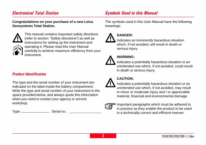
The symbols used in this User Manual have the followingmeanings:
DANGER:
Indicates an imminently hazardous situationwhich, if not avoided, will result in death orserious injury.
WARNING:
Indicates a potentially hazardous situation or anunintended use which, if not avoided, could resultin death or serious injury.
CAUTION:Indicates a potentially hazardous situation or anunintended use which, if not avoided, may resultin minor or moderate injury and / or appreciablematerial, financial and environmental damage.
Important paragraphs which must be adhered toin practice as they enable the product to be usedin a technically correct and efficient manner.
Symbols Used in this Manual
Congratulations on your purchase of a new LeicaGeosystems Total Station.
This manual contains important safety directions(refer to section "Safety directions") as well asinstructions for setting up the instrument andoperating it. Please read this User Manualcarefully to achieve maximum efficiency from yourinstrument.
Electronical Total Station
Product Identification

3TC(R)702/703/705-1.1.0en
Introduction
Operating the Instrument
Measuring Preparation
FNC Key
Start-Up Programs
Applications
Setting-Out via PC
Coding
Menu
Saving Data
Safety Directions
Care and Storage
Technical Data
Corrections and Formulae
Accessories
Index
Contents - Overview
Contents - Overview
8
14
20
41
47
54
78
80
85
116
124
138
145
149
152
153

4 TC(R)702/703/705-1.1.0enContents
Contents
Introduction ................................................... 8Special Features ......................................................... 8Important Components ................................................ 9Technical Terms and Abbreviations ............................ 10Area of Applicability ................................................... 12PC Software Package Leica SurveyOffice .................. 13
Operating the Instrument ........................... 14Keypad ..................................................................... 14Trigger Key ............................................................... 17Buttons ..................................................................... 17Symbols .................................................................... 18Menu Tree ................................................................ 19
Measuring Preparation ............................... 20Unpacking ................................................................. 20Batteries .................................................................... 21Battery Charger ......................................................... 22
Battery Charger GKL111 ................................................. 22Battery Charger GKL122 ............................................... 24Inserting / Replacing Battery ........................................... 25
Powering the Total Station from an External PowerSupply ....................................................................... 26Setting Up the Tripod ................................................. 27
Centring with Laser Plummet, Coarse Level-Up ......... 28Accurate Levelling-Up with Electronic Level................ 29Laser Intensity ........................................................... 29Centring with Shifting Tribrach ................................... 30Hints for Positioning ................................................... 30User Entries .............................................................. 31
Entry of Numeric Values ................................................. 31Entry of Alphanumeric Values ......................................... 32Inserting Characters/Numbers ........................................ 32Deleting Letters/Numbers ............................................... 33Character Set ................................................................. 34
Point Search ............................................................. 35Wildcard Search ............................................................. 37
Measuring ................................................................. 38Station Block .................................................................. 39
FNC Key ....................................................... 41EDM Change ............................................................ 41REC (Storing) ............................................................ 42Laser Pointer ............................................................. 42Tracking .................................................................... 42Target Offset ............................................................. 43Check Tie .................................................................. 44Height Determination Of Remote Points ..................... 45Delete Last Record .................................................... 46

5TC(R)702/703/705-1.1.0en
Contents, continued
Contents
Start-Up Programs ...................................... 47Setting Job ................................................................ 48Setting Station ........................................................... 49
Known Point ................................................................... 49Set Manually ................................................................... 49Height Transfer ............................................................... 50
Orientation ................................................................ 51Method 1: Set Orientation ............................................... 51Method 2: Measure Target Points ................................... 52Display of Computed Orientation .................................... 53Displaying Residuals ...................................................... 53Useful Information .......................................................... 53
Applications ................................................. 54Introduction ............................................................... 54Surveying .................................................................. 55Setting Out ................................................................ 56
Setting Out Coordinates from Memory ............................ 56Manual Input of Setting Out Values ................................. 56Polar Setout .................................................................... 57Orthogonal Setout .......................................................... 57Cartesian Setout ............................................................. 57Example ......................................................................... 58Errors ............................................................................. 58
Tie Distance .............................................................. 591. Polygonal Methods (A-B, B-C) .................................... 592. Radial Methods (A-B, A-C) .......................................... 61Extended Display ............................................................ 62Error ............................................................................... 62
Area Computation ..................................................... 63Free Station .............................................................. 65
Measuring Facilities ........................................................ 66Computation Procedure .................................................. 67Station Setup .................................................................. 67Measurements ................................................................ 68Results ........................................................................... 69Residuals ....................................................................... 70Error Messages .............................................................. 71
Reference Line .......................................................... 72Definition of the Base Line .............................................. 72Reference Line ............................................................... 74Reference Line ............................................................... 75Orthogonal Setout .......................................................... 76Notes .............................................................................. 77
Setting-Out via PC ....................................... 78
Coding .......................................................... 80Quick Code ............................................................... 84

6 TC(R)702/703/705-1.1.0en
Contents, continued
Contents
Menu ............................................................. 85Quick Settings ........................................................... 85Settings ..................................................................... 86
System Settings .............................................................. 86Angle Settings ................................................................ 89Unit Settings ................................................................... 92EDM Settings .................................................................. 93Communication .............................................................. 98Date and Time ................................................................ 99
Data Manager ......................................................... 100VIEW / EDIT DATA ....................................................... 100Delete Memory ............................................................. 105Data Download ............................................................. 106Statistics ....................................................................... 107Messages and Warnings .............................................. 108
Determining Instrument Errors ................................. 109Line-Of-Sight Error (Hz-Collimation) ............................. 110V-Index (Vertical Index Error) ........................................ 110Determining The Line-Of-Sight Error (c) ........................ 111Determining V-Index ..................................................... 112Possible Messages when Determining InstrumentErrors ........................................................................... 113
System Information ................................................. 114
Saving Data .................................................116Start-Up Programs ................................................... 116
Job ............................................................................... 116Station .......................................................................... 116Orientation .................................................................... 117
Applications .............................................................. 118Measuring Application .................................................. 118Survey Application ........................................................ 118Setting-Out Application ................................................. 118Tie Distance Application ............................................... 119Area Application ........................................................... 119Free Station Application ................................................ 119Reference Line Application ........................................... 121
Functions ................................................................ 122Determination of the Height of Remote Points .............. 122Target Offset ................................................................. 122
Correction Parameters ............................................ 122EDM ............................................................................. 122Atmospheric Corrections .............................................. 122
Coding .................................................................... 123OSW-Coding ................................................................ 123GSI-Coding ................................................................... 123
Fixed Points (Coordinates) ...................................... 123RS232 .................................................................... 123

7TC(R)702/703/705-1.1.0en
Contents, continued
Contents
Safety Directions ....................................... 124Intended Use of Instrument ...................................... 124
Permitted Uses ............................................................. 124Adverse Uses ............................................................... 124
Limits of Use ........................................................... 125Responsibilities ....................................................... 125Hazards of Use ....................................................... 126Laser Classification ................................................. 130
Integrated EDM (Infrared Laser) .................................. 131Integrated EDM (Visible Laser) .................................... 132Guide Light EGL ........................................................... 133Laser Plummet ............................................................. 134
Electromagnetic Compatibility (EMC) ....................... 135FCC Statement (Applicable in U.S.) ......................... 137
Care and Storage....................................... 138Transport ................................................................ 138
In the Field .................................................................... 138Inside Vehicle ............................................................... 139Shipping ....................................................................... 139
Storage ................................................................... 139Cleaning ....................................................................... 140
Checking and Adjusting ........................................... 141Tripod ........................................................................... 141Circular Level ............................................................... 141Circular Level on the Tribrach ....................................... 141Laser Plummet ............................................................. 142Reflectorless EDM ........................................................ 143
Technical Data ........................................... 145
Corrections and Formulae ........................ 149Atmospheric Correction ........................................... 149Reduction Formulae ................................................ 151
Accessories ............................................... 152
Index ........................................................... 153

8Introduction TC(R)702/703/705-1.1.0en
IntroductionThe Leica Geosystems TC(R)702/703/705 is a high quality electronictotal station designed for theconstruction site.Its innovative technology makes dailysurveying jobs easier.
The instrument is ideally suited forsimple construction surveys andsetting out tasks.
The operation of the instrument'sfunctions can be learned easily in ashort space of time.
Special Features
TC
700z
01
• Reflectorless measuring EDM
• Large display, alphanumerickeypad
• Endless drive
• Laser plummet
• Two axis compensator
• Camcorder batteries
• Light, slender construction
• On-board software and datamemory

9TC(R)702/703/705-1.1.0en Introduction
1 Optical sight2 Integrated guide light EGL (optio-
nal)3 Vertical drive4 Battery GEB111 (optional)5 Battery spacer for GEB1116 Battery holder for GEB111/
GEB121/GAD397 Eyepiece; focussing graticule8 Telescope focusing ring9 Detachable carrying handle with
mounting screws10 Serial interface RS23211 Foot screws12 Objective with integrated Electro-
optic Distance Meter (EDM)13 Battery adapter GAD39 for 6 sin-
gle cells (optional)14 Battery GEB121 (optional)15 Display16 Keypad17 Circular level18 On/Off key19 Trigger key20 Horizontal drive
Important Components
1 3 8 9
11 171615
2 4
TC
700Z
02
18
7
12
5 6
2010 191413

10Introduction TC(R)702/703/705-1.1.0en
Technical Terms and Abbreviations
ZA = Line of sight / collimationaxisTelescope axis = line from the reticleto the centre of the objective.
SA = Standing axisVertical rotation axis of the totalstation.
KA = Tilting axisHorizontal rotation axis of thetelescope (Trunion axis).
V = Vertical angle / zenith angle
VK = Vertical circleWith graduated scale for reading theV-angle.
Hz = Horizontal angle
HK = Horizontal circleWith graduated scale for reading theHz-angle.
ZA
ZA
KA
KAKA
SA
SA
SA
HK
VK
Hz
V
TC
700Z
24
SA

11TC(R)702/703/705-1.1.0en Introduction
Technical Terms and Abbreviations, continued
c i
Line-of-sighterror (Hz-collimation)The line-of-sighterror is thedeviation fromthe perpendicularbetween thetilting axis andthe line-of-sight.This can beeleminated bymeasuring inboth faces.
Zenith
Point on theplumb line abovethe observer.
Standing axisnclination
Angle betweenplumb line andstanding axis.
V-index(Vertical indexerror)With horizontalline-of-sight theV-circle readingshould be exactly90°(100gon).The deviationfrom this valuesis termed V-index (i).
Reticle
Glass platewithin thetelescopeengraved withthe cross hairlines.
Plumb line /Compensator
Direction ofgravity. Thecompensatordefines theplumb line withinthe instrument.
TC
700Z
37
TC
700Z
40
TC
700Z
38
TC
700Z
39
TC
700Z
13
TC
700Z
16

12Introduction TC(R)702/703/705-1.1.0en
TechnicalTerms and Abbreviations, continued
SD Indicated meteorologicalcorrected slope distancebetween instrument tilting axisand centre of prism/laser spot(TCR)
HD Indicated meteorologicalcorrected horizontal distance
dH Height difference betweenstation and target point
hr Reflector height above ground
hi Instrument height aboveground
E0 Station coordinate (Easting)
N0 Station coordinate (Northing)
H0 Station height
E Easting of target point
N Northing of target point
H Height of target point
TC
700Z
59
hrSD
dH
hiHD
E0, N
0, H
0
E, N, HThis User Manual is valid for allinstruments in the TPS700 Perfor-mance Series.
TC Instruments are equipped with aninvisible infrared EDM. The TCR In-struments are also equipped with avisible red laser for reflectorlessmeasuring.
Sections only valid for TCRinstruments are marked accordingly.
Area of Applicability

13TC(R)702/703/705-1.1.0en Introduction
PC Software Package Leica SurveyOffice
Program content
After successful installation thefollowing programs appear:
• Data Exchange Manager :For data exchange of coordinates,measurements, codelists andoutput formats between instrumentand PC.
• Codelist Manager :For creating and processing ofcodelists.
• Software Upload :For loading/deleting systemsoftware, application programsand EDM-software as well assystem/application texts.
Before the Software Upload,always insert a chargedbattery into the instrument.
• Coordinate Editor :Import/Export, creation andprocessing of co-ordinate files.
The software package LeicaSurveyOffice is used to exchangedata between the TPS700 and thePC. It contains several auxiliaryprograms to support your use of theinstrument.
Installation on the PCThe installation program for the LeicaSurveyOffice can be found on theCD-ROM supplied. Please note thatthe Leica SurveyOffice can only beinstalled under the operating systemsMS Windows 95, Windows 98 andWindows NT4.0.
To install, start the program"setup.exe " in the directory\SOffice\"Language"\Disk1 on theCD-ROM and follow the installationprogram prompts. When usingTPS700 instruments, select theoption "Standard" or "User defined"and also select TPS700 Tools.
• Settings :General settings for allSurveyOffice applications (e.g.interface parameter).
• External Tools :Access to Format Manager (user-defined output formats) and TPSSetup (user-defined basicsettings). Additional softwarepackages can be called directlyfrom here.
• Exit :Quits the SurveyOffice.
• Register :Register type of instrument andadditional objects (e.g. formats) orprograms.
For more information aboutLeica SurveyOffice, pleaserefer to the comprehensiveOnline Help.

14Operating the Instrument TC(R)702/703/705-1.1.0en
Operating the Instrument
The On/Off key is located on theside cover of the TC(R)702/703/705to avoid inadvertently switching theinstrument off.
TC
700Z
25
Buttons Symbols
Fixed keysKeys withpermanently definedfunctions (e.g.ENTER, SHIFT).
Fixed keys - 2nd levelFunctions on second key level.Can be activated by pressing
and the corresponding fixedkeys.
Keypad
Pt 13hr 1.700 m
IHz 135°54'23"V 102°12'48"HD ----.--- m
<SETUP>
RL
Focus barCurrently processed fieldor button
NavigationkeysThe navigationkeys havedifferentfunctionsdepending onthe application.
All displays shown areexamples. Local software
versions may differ from the basicversion.
Data entry keysEntry of numbers, letters, andspecial characters

15TC(R)702/703/705-1.1.0en Operating the Instrument
Fixed keys
Measure distance and angles;record measured values.
Measure distance and angles;display measured valueswithout recording.
Key, programmable withfunction from the FNC menu.
Starts application programs.
Switches the electronic levelon/off. The laser plummet isautomatically switched on withthe electronic level.
Switches to the second keylevel (EDM, FNC, MENU,illumination, ESC) andswitching betweenalphanumeric/numericcharacter set.
Deletes character/field; stopsEDM.
Confirms an entry; continue tothe next field.
Key combinations
-> +
Access to distance measuringfunctions and distance corrections(ppm).
-> +
Quick-access to measurement-supporting functions.
-> +
Access to Data Manager, instrumentsettings and adjustments.
-> +
Switches the display illumination onand off and activates the displayheating if the instrument temperatureis less than -5°C).
Keypad, continued
ESC -> +
Quit a dialog or the edit mode withactivation of the "previous" value.Return to next higher level.
PgUP-> +
"Page Up" = scrolling upwards ifseveral displays are available in onedialog.
PgDN-> +
"Page Down" = scrolling downwardsif several displays are available inone dialog.

16Operating the Instrument TC(R)702/703/705-1.1.0en
Navigation keys
/ / /
The navigation keys can take on arange of functions depending on thecontext in which they are used:
• Control of the focus• Control of the cursor• Page through a selection• Selection and confirmation of
parameters
Keypad, continued
The exact function of thesekeys will be covered in moredetail at the appropriatepoints in the User Manual.
Data entry keys
.. Entry of numbers andletters/special characters.
Entry of the decimal pointand special characters.
Change between positive/negative sign; entry ofspecial characters.
When a data entry key is pressed,the corresponding number is called.In alphanumeric data entry mode,each key is used for the entry of 3letters and a digit.If the key is repeatedly pressedquickly, the next character (letter,special character, number) is called.If the key is not pressed again withinapproximately 1 second, thecharacter is applied as an entry.
17TC(R)702/703/705-1.1.0en Operating the Instrument
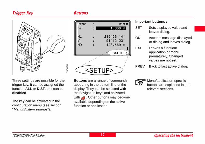
Important buttons :
SET Sets displayed value andleaves dialog.
OK Accepts message displayedor dialog and leaves dialog.
EXIT Leaves a function/application or menuprematurely. Changedvalues are not set.
PREV Back to last active dialog.
Menu/application-specificbuttons are explained in therelevant sections.
Buttons
Buttons are a range of commandsappearing in the bottom line of thedisplay. They can be selected withthe navigation keys and activatedwith . Other buttons may becomeavailable depending on the activefunction or application.
Trigger Key
Three settings are possible for thetrigger key. It can be assigned thefunction ALL or DIST, or it can bedisabled .
The key can be activated in theconfiguration menu (see section"Menu/System settings").
TC
700Z
63
<SETUP>
PtNr : M13hr : 1.600 m
Hz : 236°56'14"V : 91°12'23"HD : 123.569 m
<SETUP>
18Operating the Instrument TC(R)702/703/705-1.1.0en
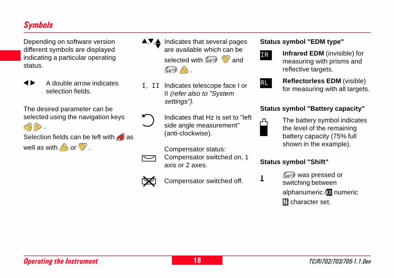
Depending on software versiondifferent symbols are displayedindicating a particular operatingstatus.
A double arrow indicatesselection fields.
The desired parameter can beselected using the navigation keys
.
Selection fields can be left with as
well as with or .
Status symbol "EDM type"
Infrared EDM (invisible) formeasuring with prisms andreflective targets.
Reflectorless EDM (visible)for measuring with all targets.
Status symbol "Battery capacity"
The battery symbol indicatesthe level of the remainingbattery capacity (75% fullshown in the example).
Status symbol "Shift"
was pressed orswitching between
alphanumeric / numeric
character set.
Symbols
IR
RL
, , Indicates that several pagesare available which can be
selected with and
.
I, II Indicates telescope face I orII (refer also to "Systemsettings").
Indicates that Hz is set to "leftside angle measurement"(anti-clockwise).
Compensator status:Compensator switched on, 1axis or 2 axes.
Compensator switched off.
19TC(R)702/703/705-1.1.0en Operating the Instrument
+
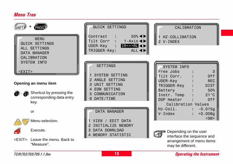
Depending on the userinterface the sequence andarrangement of menu itemsmay be different.
Menu Tree
Opening an menu item
.. Shortcut by pressing thecorresponding data entrykey.
or
Menu selection.
Execute.
<EXIT> Leave the menu. Back to"Measure".
SYSTEM INFOFree Jobs : 3Tilt Corr. : OffUSER-Key : RECTRIGGER-Key : DISTBattery : 50%Instr. Temp : 21°CDSP Heater : Off
Calibration ValuesHz-Coll. : -0.015gV-Index : +0.008g
<SW>
SETTINGS
1 SYSTEM SETTING2 ANGLE SETTING3 UNIT SETTING4 EDM SETTING5 COMMUNICATION6 DATE/TIME
CALIBRATION
1 HZ-COLLIMATION2 V-INDEX
DATA MANAGER
1 VIEW / EDIT DATA2 INITIALIZE MEMORY3 DATA DOWNLOAD4 MEMORY STATISTIC
MENU QUICK SETTINGS ALL SETTINGS DATA MANAGER CALIBRATION SYSTEM INFO
<EXIT>
QUICK SETTINGS
Contrast : 50%Tilt Corr : 1-AxisUSER-Key : IR<=>RLTRIGGER-Key: ALL

20Measuring Preparation TC(R)702/703/705-1.1.0en
8
4
Kurzanleitung
TC300 jkm kdkjodkolmdlkomömlkok
klkoklkodklkdiük9 ojokokokdo
Unpacking
Remove TC(R)702/703/705 from transport case and check for completeness:
Measuring Preparation
TC
700Z
31
1 Data cable Lemo0/RS232(optional)
2 Zenith eyepiece or eyepiece forsteep angles (optional)
3 Counterweight for eyepiece forsteep angles (optional)
4 Removable tribrach GDF111/GDF121(optional)
5 Battery charger and accessories(optional)
6 Allen key (2x)Adjusting pins (2x)
7 Battery GEB111 (optional)8 Sun filter (optional)9 Battery GEB121 (optional)
10 Mains adapter for battery charger(optional)
11 Mini prism rod (optional)12 Total station13 Mini prism + holder (optional)14 Mini target plate (only for TCR
instruments)15 Protective cover / Lens hood16 Tip for mini prism (optional)
43
5
12
13
15
6
8
7
9
14
16
11
1
10
2

21TC(R)702/703/705-1.1.0en Measuring Preparation
8
14
Only use batteries, batterychargers and accessoriesrecommended by LeicaGeosystems.
Batteries
Your Leica Geosystems instrument isoperated with rechargable plug-inbatteries. The Pro battery (GEB121)or the Basic battery (GEB111) isrecommended for TPS700 Perfor-mance Series instruments. As anoption, six individual cells can beused with the appropriate batteryadapter GAD39.
TC
700z
93
GEB111GEB121 Individual cells in thebattery adapter GAD39
Six individual cells produce a voltageof 9 Volts. The battery indicator in thedisplay is designed for a voltage of 6Volts (internal battery GEB111/GEB121) and a voltage of 12 Volts(external battery). For this reason thecharge state of individual cells is notindicated correctly. The batteryadapter with individual cells shouldtherefore be used as abackup. The advantage of individualcells is the low self-discharge rate -even over longer periods of time.

22Measuring Preparation TC(R)702/703/705-1.1.0en
8
4
Connect battery charger GKL111 tomains or inside the vehicle.Insert battery GEB111/GEB121 intothe charger so that the metalcontacts of the charger and of thebattery connect and the battery islocked in place.The continuously lit green lampindicates the charging process.
TC
700Z
74
Battery Charger
The battery chargers GKL111 orGKL122 are used to charge thebatteries. Please refer to thecorresponding battery charger usermanual for more information.
In order to fully extendbattery capacity it isabsolutely necessary tocarry out 3 to 5 completecharging/discharging cycleswith the new GEB111/GEB121 batteries.
Using the Basic battery chargerGLK111 one Basic / Pro battery canbe charged. Charging can be carriedout via a mains socket using thepower supply unit or via the vehicleconnection cable inside vehicles (12Vor 24V).
TC
700Z
73
Battery charger GKL111
Mainsconnection cable
Battery Charger GKL111
Vehicleconnectioncable

23TC(R)702/703/705-1.1.0en Measuring Preparation
8
14
As soon as the green lamp is flashingthe battery is charged and can beremoved from the charger. Chargingtime is 1 to 2 hours.Insert charged battery into the batteryholder of your instrument. Payattention to the correct polarity(corresponding to the diagram in thebattery cover).
Slide battery holder with insertedbattery into the instrument. Now theinstrument is ready for measuringand can be switched on.
Find more information in section"Inserting / Replacing Battery" or theinstruction leaflet for the chargerGKL111.
TC
700Z
75
TC
700Z
76
Battery Charger GKL111, continued

24Measuring Preparation TC(R)702/703/705-1.1.0en
8
4
Battery Charger GKL122
The Professional charger (GKL122)will charge up to four batteries, eitherfrom a 220V or 110V mains using themains plug or from the 12V or 24Vsource provided by the cigarettelighter in a vehicle. At any one time,either two Pro / Basic batteries andtwo batteries with 5-pin sockets canbe charged or, by using the adapterplate (GDI121), four Pro / Basicbatteries.
TC
700z
94
Powercable
Charger GKL122
Vehicle connection cable
Chargingcable
Adapter plateGDI121
The adapter plate can be connectedto the Pro charger (GKL122) or to theGKL23 charger, and enables two Pro/ Basic batteries to be chargedsimultaneously.
For instructions on how to use thecharger, refer to the user manual onthe charger.
TC
700z
95
ChargerGKL23
Adapter plateGDI121
The battery chargers areintended for indoor use only.
Use a battery charger in a dry roomonly, never outdoors. Chargebatteries only at an ambienttemperature between 10°C and 30°C( 50°F to 86°F ). We recommend atemperature of 0°C to +20°C (32°F to68°F) for storing the batteries.
25TC(R)702/703/705-1.1.0en Measuring Preparation
8
14
TC
700Z
06
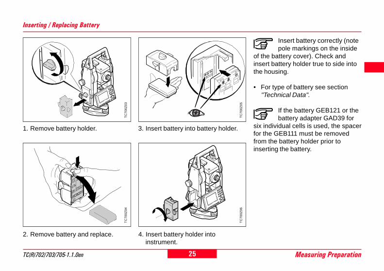
Insert battery correctly (notepole markings on the inside
of the battery cover). Check andinsert battery holder true to side intothe housing.
• For type of battery see section"Technical Data".
If the battery GEB121 or thebattery adapter GAD39 for
six individual cells is used, the spacerfor the GEB111 must be removedfrom the battery holder prior toinserting the battery.
2. Remove battery and replace. 4. Insert battery holder intoinstrument.
3. Insert battery into battery holder.
Inserting / Replacing Battery
1. Remove battery holder.T
C70
0Z03
TC
700Z
04
TC
700Z
05

26Measuring Preparation TC(R)702/703/705-1.1.0en
8
4
To comply with electromagneticcompatibility (EMC) requirementswhen supplying the TC(R)702/703/705 instruments from an externalpower supply, it is necessary to fit aso-called ferrite core to the cableused to connect the instrument to theexternal power supply.
The Lemo connector withthe ferrite core must always
be at the instrument end of the lead.
Powering the Total Station from an External Power Supply
The cables supplied by LeicaGeosystems are fitted with a ferritecore as standard. If you intend to useolder cables that are not fitted with aferrite core, the cables must be fittedwith a ferrite core prior to use.You can order ferrite cores from yourLeica Geosystems representative(spare part number for the ferritecore: 703707).
To fit the core, open it and clip it ontothe cable close to the Lemoconnector before the cable is usedwith a TC(R)702/703/705 instrument(approx. 2 cm from the Lemoconnector).

27TC(R)702/703/705-1.1.0en Measuring Preparation
8
14
TC
700Z
19
TC
700Z
32
When setting up the tripodpay attention to a horizontalposition of the tripod plate.
Heavy inclinations of the tripod platemust be corrected with the tribrachfootscrews.
TC
700Z
33
Setting Up the Tripod
1. Loosen the clamping screws onthe tripod legs, pull out to therequired length and tighten thescrews.
2. In order to guarantee a firmfoothold sufficiently press thetripod legs into the ground.When pressing the legs into theground note that the force must beapplied along the legs.
Careful handling of tripod
• Check all screws and bolts forcorrect fit.
• During transport always use thecover supplied.Scratches and other damages canresult in poor fit and measuringinaccuracies.
• Use the tripod only for surveyingtasks.
TC
700Z
57
TC
700Z
58
1. 1.
1.
2.
2.
2.
28Measuring Preparation TC(R)702/703/705-1.1.0en
8
4
TC
700Z
07
Centring with Laser Plummet, Coarse Level-Up
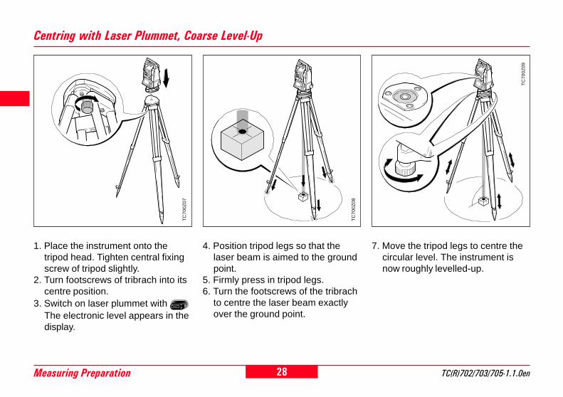
1. Place the instrument onto thetripod head. Tighten central fixingscrew of tripod slightly.
2. Turn footscrews of tribrach into itscentre position.
3. Switch on laser plummet with The electronic level appears in thedisplay.
4. Position tripod legs so that thelaser beam is aimed to the groundpoint.
5. Firmly press in tripod legs.6. Turn the footscrews of the tribrach
to centre the laser beam exactlyover the ground point.
7. Move the tripod legs to centre thecircular level. The instrument isnow roughly levelled-up.
TC
700Z
08
TC
700Z
09

29TC(R)702/703/705-1.1.0en Measuring Preparation
8
14
TC
700Z
10
1. Switch on electronic level with In the case of insuffient levelling-up an inclined level symbolappears.
3. Check centring with the laserplummet and re-centre ifnecessary.
4. Switch off the electronic level and
the laser plummet with or .
2. Centre the electronic level byturning the footscrews.
If the electronic level is centered theinstrument is levelled-up.
Accurate Levelling-Up with Electronic Level
Changing the laser intensity
External influences and the surfaceconditions may require theadjustment of the intensity of thelaser. The intensity of the laserplummet can be adjusted in 25%steps as required.
Min. 50% Max
5. The indicated laser intensity is set,and the function terminated, withthe <OK> button .
Laser plummet and electroniclevel are activated togetherwith .
Laser Intensity
20"
20"
20"
20"

30Measuring Preparation TC(R)702/703/705-1.1.0en
8
4
Positioning over pipes ordepressions
In some circumstances, the laserspot is not visible (e.g. over pipes). Inthis case, the laser spot can be madevisible by placing a sheet of transpa-rent material over the end of the pipe.
TC
700Z
35
Hints for Positioning
TC
700Z
23
If the instrument is equipped with ashifting tribrach it can be aligned tothe ground point by slight shifting.
1. Loosen screw.2. Shift instrument.3. Fix instrument by turning screw.
Centring with Shifting Tribrach
31TC(R)702/703/705-1.1.0en Measuring Preparation
8
14
User Entries
Entry of Numeric Values 1. Enter new value
Replace value displayed by newvalue:Move the focus to the required inputfield using the navigation keys
( and ). Type the numeric
value and the decimal point using thenumeric keys. The sign can bechanged from positive to negativeand vice versa at any time during
data entry using the (±) key.
concludes the entry and the focusjumps to the next input field.
Numeric fields can contain onlynumeric values, the negative signand the decimal point. Examples ofnumeric fields are: Hz (horizontalangle), E (Easting coordinate), hi(instrument height).
Numeric values can be entered intwo ways:
2. Edit value displayed
Changing only a few digits in thevalue displayed:Move the focus to the required inputfield using the navigation keys
( and ) . The key opens
Edit mode and places the cursor onthe character on the extreme right of
the field. The key opens Edit
mode and places the cursor on thecharacter on the extreme left of thefield. Move the cursor to thecharacter to be changed using the
and keys. Type the required
digit. concludes the entry and the
focus jumps to the next input field. Ifthe entry is not to be confirmed,
press and the old value will
be recalled.
32Measuring Preparation TC(R)702/703/705-1.1.0en
8
4
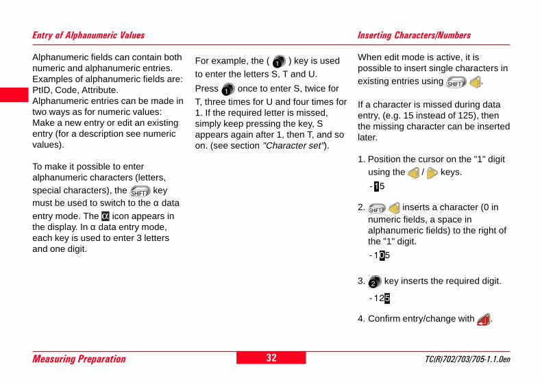
When edit mode is active, it ispossible to insert single characters inexisting entries using .
If a character is missed during dataentry, (e.g. 15 instead of 125), thenthe missing character can be insertedlater.
1. Position the cursor on the "1" digitusing the / keys.
Inserting Characters/Numbers
2. inserts a character (0 innumeric fields, a space inalphanumeric fields) to the right ofthe "1" digit.
-15
3. key inserts the required digit.
4. Confirm entry/change with .
-105
-125
Alphanumeric fields can contain bothnumeric and alphanumeric entries.Examples of alphanumeric fields are:PtID, Code, Attribute.Alphanumeric entries can be made intwo ways as for numeric values:Make a new entry or edit an existingentry (for a description see numericvalues).
To make it possible to enteralphanumeric characters (letters,special characters), the keymust be used to switch to the α data
entry mode. The icon appears inthe display. In α data entry mode,each key is used to enter 3 lettersand one digit.
Entry of Alphanumeric Values
For example, the ( ) key is used
to enter the letters S, T and U.
Press once to enter S, twice for
T, three times for U and four times for1. If the required letter is missed,simply keep pressing the key, Sappears again after 1, then T, and soon. (see section "Character set").

33TC(R)702/703/705-1.1.0en Measuring Preparation
8
14
When edit mode is active, individualcharacters in an entry can be deleted
using the key.
Example:
Deleting Letters/Numbers
The cursor jumps to the next
character. If you press
repeatedly, character after characteris deleted until the input field isempty.
Pressing again restores the entry
as it was prior to editing.
Numeric values aredisplayed in a fixed format
with digits after the decimal point,even if the digits are zero. Digits afterthe decimal point are not deleted by
, but set to zero.1ABC32 1AB32
If the focus is on an inputfield, but edit mode is not
active, deletes the entire entry. If
is pressed again, the old value is
restored.

34Measuring Preparation TC(R)702/703/705-1.1.0en
8
4
NumericCharacter Set
Key Numeric Alpha1 Alpha2 Alpha3 Alpha4
0 / $ % 0
. # @ & .
+/- * ? ! -
1 S T U 1
2 V W X 2
3 Y Z [space] 3
4 J K L 4
5 M N O 5
6 P Q R 6
7 A B C 7
8 D E F 8
9 G H I 9
Character Set
In data fields where searches areperformed for point numbers orcodes, it is also possible to enter the"*" character.
Sign+/- In the alphanumeric character set,
"+" and "-" are treated as normalalphanumeric characters. i.e. theyhave no mathematical function.
Special characters* Place holder for WILDCARD point
searches (see section "WildcardSearch").
"+" / "-" appears only in thefirst position of an entry.
In edit mode, the position ofthe decimal point cannot be
changed. The decimal point isskipped.
Alphanumeric Character Set
35TC(R)702/703/705-1.1.0en Measuring Preparation
8
14
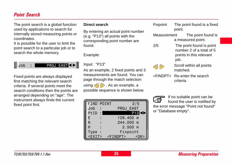
Point Search
The point search is a global functionused by applications to search forinternally stored measuring points orcoordinates.It is possible for the user to limit thepoint search to a particular job or tosearch the whole memory.
Job : PROJ_EAST
Fixed points are always displayedfirst matching the relevant searchcriteria. If several points meet thesearch conditions then the points arearranged depending on "age". Theinstrument always finds the currentfixed point first.
Direct search
By entering an actual point number(e.g. "P13") all points with thecorresponding point number arefound.
Example:
Input: "P13"
As an example, 2 fixed points and 3measurements are found. You canpage through the match selection
using . As an example, apossible sequence is shown below.
FIND POINT 2/5Job : PROJ_EASTPtID : P13E : 128.400 mN : 244.000 mH : 2.500 mType : Fixpoint<EXIT> <FINDPT> <OK>
Fixpoint The point found is a fixedpoint.
Measurement The point found isa measured point.
2/5 The point found is pointnumber 2 of a total of 5points in this relevantjob.
Scroll within all pointsmatched.
<FINDPT> Re-enter the searchcriteria.
If no suitable point can befound the user is notified by
the error message "Point not found"or "Database empty".

36Measuring Preparation TC(R)702/703/705-1.1.0en
8
4
Point Search, continued
Point number Time of recording
At the end of the measuredpoints the search returns tothe beginning of the fixedpoints.
TC
700Z
89
... ....
P13 14:52:10
... ....
P13 15:34:55
... ....
... ....
... ....
... ....
P13 14:59:01 ... .... ... ....
P13 15:46:12
P13 16:18:38 ... .....
Fixed points
Measurements
Point search is always started withthe last recorded point.The last entered/measured points aredisplayed first; fixed points beforemeasured points.
Scroll through the list ofpoints found.
Found:
P13, fixed point, time: 15:34:55
P13, measurement, time: 14:59:01
P13, measurement, time: 15:46:12
P13, measurement, time: 16:18:38
P13, fixed point, time: 14:52:10
to start of list !
Pointfoundfirst

37TC(R)702/703/705-1.1.0en Measuring Preparation
8
14
Wildcard Search
The Wildcard search is indicated by a"*" . The asterisk is a place holder forany following sequence ofcharacters.
Wildcards are always used if thepoint number is not fully known, or ifa batch of points is to be searchedfor.
Examples:
* all points of any length arefound.
A all points with exactly thepoint number "A" are found.
A* all points of any lengthstarting with "A" are found(e.g.: A9, A15, ABCD)
*1 all points of any length witha "1" at the second placeare found(e.g.: A1, B12, A1C)
A*1 all points of any length withan "A" at the first place anda "1" at the third place arefound (e.g.: AB1, AA100,AS15)
Definitions
Fixpoint The point found is a fixedpoint.
Measurement The point found is ameasured point.
2/5 The point found is pointnumber 2 of a total of 5points in this relevantjob.
Scroll within all pointsfound.
<FINDPT> Re-enter the searchcriteria.
Starts point search.
FINDPOINT
Job : PROJ_4PtID : S*

38Measuring Preparation TC(R)702/703/705-1.1.0en
8
4
Measuring
After switching on and setting upcorrectly, the total station isimmediately ready for measuring.
TC
700Z
25
Example of a possible measuringdisplay:
In the measuring display calling allfunctions/applications under FNC,EDM, PROG, MENU, LIGHT, LEVEL-and LASER-PLUMMET is possible.
All displays shown areexamples. Local software
versions may differ from the basicversion.
Displays
Indicates further displays withadditional data (e.g. dH, SD,E, N, H, ....)
: Changes the display.
<Hz0> Set the Hz-orientation to0°00'00" / 0 gon.
Angles are permanentlydisplayed. At the time ofpressing the key a distancemeasurement is triggered.The angle values anddistance are stored in theinternal memory ordownloaded via serialinterface.
Triggers a distancemeasurement and shows thison the display. Angles aredisplayed independently ofthe distance measurement.The displayed distanceremains valid until it isreplaced by a new distancemeasurement.
PtID : M13hr : 1.600 m
Hz : 236°56'14"V : 91°12'23"HD : 123.569 m
<QCODE> <Hz0> <SETUP>

39TC(R)702/703/705-1.1.0en Measuring Preparation
8
14
This dialog generates a station blockwithout co-ordinates which can beevaluated by software.
In the data output the data is madeavailable depending on theevaluation possiblitie. The orientationis manual.
Station Block
Orientation:The orientation is designated with thenumber and description of the targetpoint.
2) Move cursor to "BsPt" and enterorientation point number. Close
entry with .3) Manual input of a Hz value as
orientation or set <Hz0>.
The orientation is continuouslydisplayed but can be modified in theedit mode.
Buttons:<SET> The entries are registered
and the measuring displayis activated again.
<STN> Starts manual input of thestation coordinates.
TC
700Z
79
Procedure:<SETUP> This button in the
measuring display activatesthe definition of station andorientation.
Station:The station can be defined with astation name.
1) Move cursor to "Stn" and enterstation number as well asinstrument height "hi". Close entry
with .
SETUPStn : 100hi : 1.500 m
BsPt: 101BsBrg : 0°00'00"
<EXIT> <JOB> <STN> <SET>

40Measuring Preparation TC(R)702/703/705-1.1.0en
8
4
Station Block , continued
STATIONStn : 23
E0 : 1475687.345 mN0 : 1693405.602 mH0 : 1243.932 m
<EXIT><ENH=0><PREV><SET>
1. Move cursor to the required line.
Close entry with .
2. <SET>: The entries are registeredand the measuring display isactivated again.
<ENH=0> The station co-ordinatesare set to (0/0/0).
<EXIT> Back to measuring displaywithout saving.
Manual input of the stationcoordinates:
Within this dialog, the name, theheight and the station co-ordinates ofthe instrument can be set manually.
<PREV> Back to setup display.

41TC(R)702/703/705-1.1.0en FNC Key
8
14
20
FNC Key
With "FNC" ( + ) differentfunctions are available.
Application of individual functions aredescribed in this section.
Functions can also be started directlyfrom the different applications.
Each function from the FNCmenu can be assigned to the
key (see section "Menu/Settings").
Each function can be startedeither using the shortcut with
the corresponding data entry key orselected with / and the
selection confirmed with . In thisUser Manual only the shortcutmethod of starting the functions isgiven.
EDM Change
Shortcut to the function"IR<=>RL".
Change between the two EDM typesIR (Infrared) and RL (Reflectorless).New setting is displayed for aboutone second.
IR: Infrared: Distancemeasurements with prisms.
RL: Visible laser: Distancemeasurements without prismsup to 80m; with prisms from1 km.
Find more information in section"EDM Settings".
FUNCTIONS 2
5 OFFSET6 CHECK TIE7 REMOTE HEIGHT (REM)8 DEL. LAST REC. (DLR)
<EXIT>
FUNCTIONS 1
1 IR<=>RL RL2 REC3 LASERPOINTER On4 TRACKING OFF
<EXIT>

42FNC Key TC(R)702/703/705-1.1.0en
8
4
0
Laser Pointer
Shortcut to the function"LASERPOINTER".
Switches on or off the visible laserbeam for illuminating the target point.The new setting is displayed forapprox. one second and then set.
The last active measurement moderemains set when the instrument isswitched off.
Tracking
Shortcut to the function"TRACKING".
Switches on or off the trackingmeasurement mode. The new settingis displayed for approx. one secondand then set. The function can onlybe activated from within the sameEDM type and prism type.
The following options are available:
REC (Storing)
Shortcut to the function"REC".
Actual measured data is stored by"REC" to the internal memory or viathe serial interface.
By activating "REC" the followingactions are carried out:
• Recording a measurement block.
• Incrementing of current pointnumber.
EDM Type Tracking measurementmodeOff <=> On
IR IR-Fine <=> IR_TrackIR-Fast <=> IR-Track
RL RL-Short <=> RL-Track

43TC(R)702/703/705-1.1.0en FNC Key
8
14
20
Target Offset
Shortcut to the function"OFFSET".
If it is not possible to set up thereflector directly, or it is not possibleto aim the target point directly, theoffset values (length, cross and/orheight offset) can be entered. Thevalues for the angle and distancesare calculated directly for the targetpoint.
3D OFFSETPtID : 23hr : 1.500 mL_Offset : 2.200 mT_Offset : 3.660 mH_Offset : 1.780 mMode: Permanent <EXIT> <SET>
Procedure:1. Enter the point ID and the reflector
height2. Enter the offset values (length,
cross and/or height) as per thesketch
3. Define the period for which theoffset is to apply.
4. <SET> calculates the correctedvalues and jumps to theapplication from which the offsetfunction was started. Thecorrected angle and distances aredisplayed as soon as a validdistance measurement has beentriggered or exists.
<EXIT> Leaves the function andreturns to the applicationfrom which the function wasstarted.
Changes to 2D target offset(without entry of the heightoffset).
The period of applicability can be setas follows:
The function can only bestarted in the applications
"Measuring" and "Surveying". Theoffset values are always reset to 0when the application is quit.
TC
700Z
96
Offs.Cross +
Offs
.Lng
th +
Offset PT.MeasurementPoint
Offs.Cross -
Offs
.Lng
th -
Elev. +:Offset point ishigher thanmeasurement
Reset afterREC
The offset values arereset to 0 after the pointis saved.
Permanent The offset values areapplied to all furthermeasurements.

44FNC Key TC(R)702/703/705-1.1.0en
8
4
0
Check Tie
Shortcut to the function"CHECK TIE".
Calculation and display of the slopeand horizontal distance, heightdifference, azimuth, and co-ordinatedifferences between the last twomeasured points. Valid distancemeasurements are required for thecalculation( , ).
CHECK TIEBrg : 85°19'35"Hdist: 9.011 mSdist: 9.059 mdE : 8.768 mdN : 2.077 mdH : 0.939 m<EXIT>
The function can only be started inthe "Measuring" and "Surveying"applications. New measurementsmust be made after changing to a dif-ferent application.
TC
700Z
91
Sdist
dH
Hdist
Azi
NImportant Messages Meaning
Check tie not possible! The function can only be activated in the"Measuring" and "Surveying" applications.
Less than 2 validmeasurements!
The values cannot be calculated as thereexist less than 2 valid measurements.

45TC(R)702/703/705-1.1.0en FNC Key
8
14
20
Height Determination Of Remote Points
Points directly above the base prismcan be determined without a prism atthe target point.
Measure base point:
1. Enter point number and prismheight.
Determine remote point:
3. Aim at the remote point with thetelescope .
TC
700Z
15
BASE POINT Pt1
Pt1 : 100hr : 1.600 mHD : ----.--- m
<EXIT> <MEAS>
2. Trigger distance measurement andindication of horizontal distance(HD) with <MEAS>.
<MEAS> Measure and record thebase point.
REMOTE POINT Pt2Pt1 : 100Pt2 : 101dH : 8.346 mH : 512.042 mHD : 70.571 m
<EXIT> <NEWBASE> <MEAS>
Remote point
Base point
Slope distance
Hei
ght
diff.
4. Store with <MEAS> measureddata of the remote point. No newdistance measurement is carriedout.
Height (H) and height difference (dH)as function of actual V-angle andmeasured distance to base point arecomputed and displayed immediately.
<NEWBASE> Enter and measure anew base point.
Shortcut to the function"REMOTE HEIGHT (REM)".

46FNC Key TC(R)702/703/705-1.1.0en
8
4
0
Delete Last Record
Deleting the last record is notreversible !
Only records can be deletedwhich were recorded in"Surveying" or in "Measuring".
Shortcut to the function "DEL.LAST REC. (DLR)".
This function deletes the lastrecorded data block. This can beeither a measurement block or acode block.
DELETE LAST RECORD
SURE TO DELETE ?
<NO> <YES>
Important messages Meaning
Not permitted to delete recordoutside "Surveying" or in"MEASURING"
Function "DELETE LAST RECORD" isonly active in applications "Surveying"and "MEASURING".
Output set to RS232 Current setting for data storage is"RS232" (see section"Configuration"). Measured data hasbeen output via interface and socannot be deleted in the field memory.
Not permitted to delete this record Record cannot be deleted becauselast data set was not registered eitherin "Surveying" nor in "MEASURING".
Last record has been deleted The last record has been alreadydeleted. Function cannot be activatedany more.

47TC(R)702/703/705-1.1.0en Start-Up Programs
8
14
20
Start-Up ProgramsStart-up programs are a set offunctions for successful stationssetup and data management. Theuser can select start-up programsindividually.
Opens the program menu,execute an application with
.
Error messages:
"SET A JOB FIRST""NO JOB IN SYSTEM"• No valid job set.> Carry out "SET JOB" and select a
valid job or generate a new one.
"SET A STATION FIRST""NO STATION IN SYSTEM"• No valid station defined in the job.> Carry out "SET STATION" and
define a valid station. Note that ajob was already set.
"SET ORIENTATION FIRST""NO ORIENTATION IN SYSTEM"• No orientation set in the job.> Carry out "SET ORIENTATION"
and make sure that JOB andSTATION are valid.
A "•" indicates that a job is set andthat in the job set the last station/orientation in the memory correspondto the actual station/orientation.
SETTING OUT
1[�] SetJob2[�] SetStation3[ ] SetOrientation4 Start
<EXIT>
.. Shortcut to a start-upprogram by pressing thecorresponding data entrykey
or
Select or skip a start-upprogram. The selection ismarked by the black bar.
Execute the marked start-up program.
<EXIT> Quits the start-up programsand returns to the programmenu or selection of a newapplication.
Find further information aboutindividual start-up programson the subsequent pages !

48Start-Up Programs TC(R)702/703/705-1.1.0en
8
4
0
All data is saved in JOBS, likedirectories. Jobs containmeasurement data of different types(e.g. measurements, codes, fixedpoints, stations,...) and areindividually manageable and can bereadout, edited or deleted separately.
If a job was not yet defined and or REC is activated in "MEASURE"the system automatically generates ajob with name "DEFAULT".Using the SurveyOffice softwarepackage TPS300/700 Tools "TPSsetup" the number of available jobscan be either set to 8 (mixed datamanagement: measurements andfixed points) or to 16 (onlymeasurements or only fixed points).
Setting Job
Re-enter Job
<NEW> Defines a new job.Activates a display for inputof a new job name anduser.
<SET> Sets job and returns tostart-up program overview.
<EXIT> Back to start-up programoverview.
All subsequent recorded datais stored in this job/directory.
Date and time areautomatically placed by thesystem and cannot bechanged.
SelectionUsing the arrow keys you can scrollwithin the available jobs. Select thedesired job.
1/2 Job no 1 of a total of twoavailable jobs.
Remarks
SELECT JOB 1/2
Job : Project_A05Oper : R.FISCHERDate : 04/07/1998Time : 16:42
<EXIT> <NEW> <SET>

49TC(R)702/703/705-1.1.0en Start-Up Programs
8
14
20
Setting Station
Each co-ordinate computation relatesto the currently set station.Therefore, at least station point planco-ordinates (E0, N0) are required.The station height can be enteredoptionally. The co-ordinates can beentered either manually or read fromthe internal memory.
H N
EN0
E0
1. Enter a point number from thememory.
2. <SET>Sets and records station co-ordinates. Return to start-upprogram overview.
3. Wildcard search enables theglobal search for points in thecomplete memory (all jobs).
: Extends the display.
<H0-TRANS> Starts the "HEIGHTTRANSFER" function.
TC
700Z
86
Set Manually
If an entered point number cannot befound in the internal memory then themanual input is activatedautomatically.
1. Enter Point ID.
2. Enter co-ordinates and height.
3. <OK> : Sets and records stationco-ordinates. Return to "SETSTATION".
Known Point
SET STATIONStn.: 200hi : 1.600 m
E0 : 1000.000 mN0 : 1000.000 mH0 : 1000.000 m<EXIT> <H0-TRANS> <SET>

50Start-Up Programs TC(R)702/703/705-1.1.0en
8
4
0
Expands the display.<MAN> Opens manual height entry.
Height Transfer
The height transfer function definesthe height of the position of theinstrument from measurements to atarget point of known height.
Procedure:1. <H0-TRANS> in the "SET STATI-
ON" display starts the heighttransfer and carries out a pointsearch using the wildcard criterion(*), i.e. the last point measured/entered is displayed first, fixedpoints before measurements.
2. Enter the required point numberfor the target point or page throughthe list of points found using
.
3. / / <MEAS>:Measurement to the selectedtarget point.
4. <RES>: display of the results.
RESULTSStn : STN1PtID : PF22H0 I : 436.719 mH0 II: 435.065 mMean : 435.892 m
<EXIT><PREV> <NEW> <OK>
The following are displayed:• Station name• Point ID of the target point• Calculated station height (H0) from
measurement in the correspondingtelescope face. If measurementsare performed in both telescopeface, the measurements areaveraged.
If the calculated values forH0 in the first and second
telescope face vary by more than10cm, an error message is displayed.The measurement does not need tobe repeated, H0_MEAN is calculatedin any case.
<OK> Back to the SET STATIONdisplay, H0 is set and onlysaved with <SET>.
<NEW> Starts a new measurement<EXIT> Ends the height transfer,
returns to SET STATIONdisplay (H0 is not set).
<PREV> Back to the measurementdialog.
TC
700Z
92 E,N,H
E0,N0;H0 = ?
Sdist
Hdist
HEIGHT TRANSFER PtID: *
PF22Measurement
hr : 1.670 mHD : ---.--- mdH : ---.--- m<EXIT> <RES> <MEAS>

51TC(R)702/703/705-1.1.0en Start-Up Programs
8
14
20
Orientation
This program enables an orientationangle to be entered manually, or forthe orientation to be determined bymeasurement to points with knownco-ordinates.
Orientation co-ordinates can beeither obtained from the internalmemory or entered manually. Usingbutton <Hz0> the orientation can beset to 0.000 quickly and easily.
The system offers the followingpossibilities:
• Set any Hz-value manually.
• With <Hz0> set Hz=0.000.
• Orientation to target points withknown co-ordinates.
Method 1: Set Orientation
Set any Hz-orientation
By entering the Hz-angle the usercan set any Hz-orientation.
Moves cursor to input field"BsBrg".
Enters new angle.
Deletes field or sets to0°00'00".
Set Hz0
Using button <Hz0> the orientationcan be set to 0.000 quickly andeasily.
<Hz0> Set Hz-orientation to0°00'00".
<SET> Confirms the orientation ifno entry has been made, orsets and records the neworientation if a new point IDhas been entered, or a newHz-angle has been set.
Optionally, an alphanumericpoint number and a
description can be added to theorientation block.
ORIENTATION (Set new or confirm)
BsPt: 101BsBrg: 0°00'00"
<EXIT><Hz0> <COORD><SET>

52Start-Up Programs TC(R)702/703/705-1.1.0en
8
4
0
Method 2: Measure Target PointsT
C70
0Z14
1. Targetpoint
2. Targetpoint
3. Target point
Hz=
0
Hz1
For determining the orientation, amaximum of 5 target points withknown co-ordinates can be used.
Orientation co-ordinates can beeither obtained from the internalmemory or entered manually.
If an orientation point number cannotbe found in the internal memory thenthe instrument automatically activatesthe manual entry of the co-ordinates.
<COORD> Activates input/edit modefor entry of a knownorientation point.
1/I Status indication;shows that first pointwas measured intelescope face I.
1/I II First point measured intelescope face I and II.
dHz: After the firstmeasurement thefinding of other targetpoints (or the samepoint when changingthe telescope position)is easier by setting theindicated angledifference near to0°00'00" by turning theinstrument.
dHD: Difference betweenhorizontal distance totarget point computedfrom co-ordinates andthe measureddistance.
<MEAS> An angle and a distancemeasurement is triggered.If no distance can bemeasured only an anglemeasurement is made.
Dialog for orientation toseveral target points.
ORIENTATION 1/I IIBsPt : 201hr : 1.300 mBsBrg: 236°56'14"dHz : +51°12'23"dHD : 0.569 m
<MEAS> <SET>

53TC(R)702/703/705-1.1.0en Start-Up Programs
8
14
20
Displaying Residuals Useful Information
• If the orientation is only measuredin telescope face II the Hz-orientation is based on telesopeface II. If measured only intelescope face I or mixed the Hz-orientation is based on telescopeface I.
• The prism height may not bechanged during measurements inthe first and second telescopeface.
• If a target point is measuredseveral times in the sametelescope face the last validmeasurement is used for thecomputation.
TC
700Z
80
dHD (-)
dOffs (+)dHz (+)
<RESI> Displays residuals.
dH: Height residualsdHD: Correction on the horizontal
distancedHz: Correction on Hz-angle.
Display of Computed Orientation
<OK> Sets computed Hz-orientation.
If more than one target point ismeasured then the orientation iscomputed using the "least squaresmethod".
<SET> Displays orientation resultsif several target points aremeasured.
ORIENTATION RESULT
NoPts : 2Stn : 200HzCor . 123°00'23"StDev : ± 0°00'08"
<EXIT> <RESI> <OK>
actual
design
RESIDUALS 1/3
BsPt : ABC1dHz : 0°00'23"dHD : -0.045 mdH : 0.075 m
<EXIT> <PREV> <OK>

54Applications TC(R)702/703/705-1.1.0en
8
4
0
ApplicationsDepending on local softwareversions the contents of the
displays (lines) described in thissection can differ. However, thefunction of the relevant displayremains the same.
Before starting anapplication, make sure the
instrument is perfectly levelled upand the station data is correctly set.
Button functions
Triggers a distancemeasurement.
Measures and records themeasured values.
When starting anapplication the dialog withthe Start-up programs iscalled automatically (seesection "Start-Up Programs").
With these onboard applications thefunctionality of the TC(R)702/703/705instruments is improved considerably.As a result, the functionality is exten-ded and the daily surveying fieldworkis made easier. By using internallyrecorded values the user is mainlyprotected from entering incorrectdata. Points with given coordinatesas well as measured points can beused within the programs.
The following programs are availablein the internal memory:
• Surveying• Setting Out• Tie Distance• Area• Free Station• Reference Line
Introduction
Opens the program menus.
PROGRAM1 SURVEYING2 SETTING OUT3 TIE DISTANCE4 AREA (PLAN)5 FREE STATION6 REFERENCE LINE<EXIT>
.. Start the requiredapplication directly bypressing the correspondingdata entry key.
Or
Selects the desiredapplication.
Opens the application andactivates the Start-upprograms.

55TC(R)702/703/705-1.1.0en Applications
8
14
20
Procedure:
1. Input of point number.2. Input of code, if required (see also
"CODING")3. Enter new reflector height or
change the existing height.4. Trigger and record measurements
with , or (if REC isassigned).
<QCODE> Start the "Quick Code"function
Find further informationabout coding or about quickcode in section "CODING".
With / you can switchquickly and easily between differentdisplays.
Surveying
With the program "Surveying" themeasuring of an unlimited number ofpoints is supported. The program canbe compared to simple measuring.Only the guided stationing ororientation (see section "Start-UpPrograms") and the additional displayfor target co-ordinates are different.
TC
700Z
48
Measured data can either berecorded in the internal
memory or output via serial interfaceRS232 (see "Configuration / InterfaceParameter").
Measuring display 1
Measuring display 2
Hz : 123°12'34"SD : 406.542 mdH : 72.081 m<EXIT> <QCODE>
Measuring display 3
E : 1739.420 mN : 932.711 mH : 456.123 m<EXIT> <QCODE>
SURVEYING 1PtID : AB-12hr : 1.600 mCode : BaumHz : 123°12'34"V : 79°56'45"HD : 412.883 m<EXIT> <QCODE>

56Applications TC(R)702/703/705-1.1.0en
8
4
0
Setting Out
The application computes setting-outelements for the polar, cartesian ororthogonal setting out of pointsusing either co-ordinates or manuallyentered angle, horizontal distanceand height. Setting out differencescan be displayed continuously.In the Setting out program threedifferent displays are availableshowing setting out valuescorresponding to the relevantmethod.
Switches the display andmethod.
A point search with the wildcardcriterion (*) is automaticallyperformed on starting setting-out, i.e.the last point measured/entered isdisplayed first, fixed points beforemeasurements. Points can be easilyselected by scrolling through with / .
Additionally, the type of the pointfound (fixed point or measured point)is displayed.
Input a point number.If the desired point number could notbe found the system opens themanual co-ordinate entryautomatically (see example).
Setting Out Coordinates from Memory
<B&D> Switches the instrument to"Manual input of setting outvalues".
Changes to 3D set out.
Manual Input of Setting Out Values
BEAR & DIST ENTRY
PtNr : ABC1Azi : 123°12'36"Dist : 123.569 mH : 12.456 m
<EXIT> <PREV> <SET>
1. Enter direction (Brg), horizontaldistance (Dist) and height (H) ofsetout point.
2. <SET> : The entered data is set.Calling the setting out dialog.
3. Trigger measurement with or
.4. The setout offsets are displayed in
the same way as with the polarsetout.
<PREV> Changes to 2D/3D settingout (ref. to section "Settingout co-ordinates frommemory").
2D-SET OUTPtID : C1*
P100Fixpoint
Dist : 10.200 mdHz : +30°25'14"dHD : 4.782 m<EXIT> <B&D>

57TC(R)702/703/705-1.1.0en Applications
8
14
20
Polar Setout
TC
700Z
41+dHz
+dHD
Normal indication of polar setoutoffsets dHz, dHD, dH.
The position offset betweenmeasured point and setout point isindicated in a longitudinal and trans-versal element.
TC
700Z
47
Actual
+dL
point to besetout
+dT
dL: Longitudinal offset: positiveif nominal point furtheraway.
dT: Transversal offset,perpendicular to line-of-sight: positive if nominalpoint is to the right ofmeasured point.
dHz
Cartesian SetoutOrthogonal Setout
dHz: Angle offset: positive ifpoint to be setout is to theright of the actual direction.
dHD: Longitudinal offset: positiveif point to be setout isfurther away.
dH: Height offset: positive ifpoint to be setout is higherthan measured point.
TC
700Z
42
+dE+dN
E
N
Setting out is based on a coordinatesystem and the offset is divided into anorth and east element.
dE Easting offset betweensetout and actual point.
dN Northing offset betweensetout and actual point.
point to be setout point tobe setout
ActualActual

58Applications TC(R)702/703/705-1.1.0en
8
4
0
Errors
No or invalid PtId or coords:• The point number entered is not
available.> Re-enter point number/co-
ordinates.
Invalid entries of data:• Manually entered setting out data
is incomplete (e.g. setting outdistance missing).
> Check setout parameter and re-enter.
By entering a wildcard (*), a group ofpoints can be found easily and setout one after the other.
Example
Procedure:1. Enter "C1*" in the "PtID" field.
2. starts the point search andfinds all points that meet thesearch criterion (e.g. C10, C11,C12, …)
3. Using you can page quicklythrough the points found.
FIND POINT 3/6Job : Proj_A4PtID : C12E : 735.482 mN : 633.711 mH : 141.581 mType : Fixpoint<EXIT> <FINDPT> <OK>
<EXIT> Leaves point search withoutselecting a point. Back tosetting-out.
<FINDPT> Re-enter the searchcriteria.
4. <OK> Selects the required pointand returns to setting-out.
2D-SET OUTPtID : C1*
P100Fixpoint
Dist : 10.200 mdHz : +30°25'14"dHD : 4.782 m<EXIT> <B&D>

59TC(R)702/703/705-1.1.0en Applications
8
14
20
Tie Distance
The application Tie Distancecomputes slope distance, horizontaldistance, height difference andazimuth of two target pointsmeasured online , selected from theMemory or entered using theKeypad .
Distances and directions betweentwo successive points aredetermined and can be saved in theinternal memory (e.g 3 to 4).
TC
700Z
85
T101
T202
T303
Az 1-2
Az 2-3
dSD 1-2
dSD 2-3
Hz=
0°00
'00'
'N
1. Enter desired point number andreflector height for the first targetpoint.
TIE DISTANCE PT 1Pt1 : T101hr : 1.300HD : 102.501 m
1. Polygonal Methods (A-B, B-C)
The user can choose between twodifferent methods:
TIE DISTANCE
1 Polygonal (A-B, B-C)2 Radial (A-B, A-C)
<EXIT>
60Applications TC(R)702/703/705-1.1.0en
8
4
0
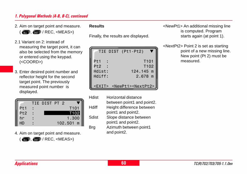
2. Aim on target point and measure.( , / REC, <MEAS>)
2.1 Variant on 2: instead ofmeasuring the target point, it canalso be selected from the memoryor entered using the keypad.(<COORD>)
3. Enter desired point number andreflector height for the secondtarget point. The previouslymeasured point number isdisplayed.
4. Aim on target point and measure.( , / REC, <MEAS>)
TIE DIST PT 2Pt1 : T101Pt2 : T102hr : 1.300HD : 102.501 m
1. Polygonal Methods (A-B, B-C), continued
Hdist Horizontal distancebetween point1 and point2.
Hdiff Height difference betweenpoint1 and point2.
Sdist Slope distance betweenpoint1 and point2.
Brg Azimuth between point1and point2.
<NewPt1> An additional missing lineis computed. Programstarts again (at point 1).
<NextPt2> Point 2 is set as startingpoint of a new missing line.New point (Pt 2) must bemeasured.
TIE DIST (Pt1-Pt2)
Pt1 : T101Pt2 : T102Hdist: 124.145 mHdiff: 2.678 m
<EXIT> <NewPt1><NextPt2>
Results
Finally, the results are displayed.

61TC(R)702/703/705-1.1.0en Applications
8
14
20
2. Aim on target point and measure.( , / REC, <MEAS>)
2.1 Variant on 2: instead ofmeasuring the target point, it canalso be selected from the memoryor entered using the keypad.(<COORD>)
3. Enter desired point number andreflector height for the secondtarget point. The previouslymeasured point number isdisplayed.
4. Aim on target point and measure.( , / REC, <MEAS>)
Results
Finally, the results are displayed.
<NewCP> Measure new centrepoint. Program startsagain (at point 1).
<NextRP> Measure new radialpoint (centre point Pt. 1is retained)
1. Enter desired point number andreflector height for the first targetpoint.
2. Radial Methods (A-B, A-C)T
C70
0Z10
3
1
2
3
4
Az 1-2
Az 1-3
Az 1-4
Centrepoint
Hz=
0°00
'00'
'
NSlope distance 1-2
Slopedistance 1-3
Slope distance 1-4
CENTRE POINTPt1 : 15hr : 1.600HD : --.--- m
RADIAL POINTPt1 : 15Pt2 : 16hr : 1.600HD : --.--- m
RADIAL DIST (1-2)
Pt1 : 15Pt2 : 16Hdist: 2.359 mHdiff: 1.003 m
<START> <NewCP> <NextRP>

62Applications TC(R)702/703/705-1.1.0en
8
4
0
Extended Display
Error message"No Distance measured"
• Distance measurement has notbeen carried out or not saved.
> Make the measurement again.
Error
Changes between displaysshown above and below.
TIE DIST PT 1Pt1 : T101hr : 1.300 mHz : 222°45'42"V : 87°30'55"HD : 102.501 m
<EXIT> <MEAS>
TIE DIST PT 1Pt1 : T101hr : 1.300 mHD : 102.501 m
On the measurement of the targetpoints and when displaying results,additional angle and distanceinformation can be displayed.

63TC(R)702/703/705-1.1.0en Applications
8
14
20
Area Computation
The application areas (plane)computes online areas from anunlimited number of points connectedby straight lines.
From three measured points the areais computed and displayed on-line.By activating <RESULT> the numberof points used, the computed areaand the closed polygonal length (e.g.line 1-2-3-4-1) are displayed.
The points can be measuredoptionally in the first or
second telescope face. Between theindividual points the telescope facecan be changed. One distance mustalways be measured.
TC
700Z
341
2 3
4
5
Start
Actual area, alwaysclosed to the startingpoint (1).
Polygonal length, fromstarting point to theactual measured point.

64Applications TC(R)702/703/705-1.1.0en
8
4
0
Area Computation, continued
The area is always displayedaccording to the onboard unitsetting ( m², hectare).
Displayed are:• area• number of measured points• circumference of closed area/
length of closed polygon.
<NEW> Starts a new areacomputation. Thecounter is set to "0"again.
<EXIT> Quits the program areacomputation.
AREA-RESULTS
NoPts: 15Area : 148.472 m2Area : 0.014 haPerim: 65.241 m
<EXIT> <NEW>
1. Input of point number.
2. Trigger a distance measurement:This can be achieved in thefollowing ways:
<MEAS> Triggers and records ameasurement. Pointcounter and pointnumber areincremented.
Same function as<MEAS>.
Triggers anddisplays a distancemeasurement.
REC Save with REC if key
is assignedaccordingly.
<RESULT> Records areas,perimeter and pointcounter.
AREA (plan)PtID: 1hr : 1.500 mHD : ---.-- mArea : 0.000 m2Pts : 1
<EXIT> <RESULT> <MEAS>
ResultsMeasuring display

65TC(R)702/703/705-1.1.0en Applications
8
14
20
Free Station
The application "Free Station" is usedto determine the instrument positionfrom measurements to a minimum oftwo known points and a maximum offive known points.It supports measurements to pointsusing either distances and Hz- and V-angles (typical 2 point resection) orangles only (typical 3 point resection)or a combination of angles anddistances to different points.
The following measurementssequences to target points arepossible:1. Hz- and V-angles only,2. Distance and Hz- and V-angle,3. Hz- and V-angles to some point(s)
and Hz- and V-angle plus distanceto other point(s).
The final computed results areEasting, Northing and Height of thepresent instrument station, includingthe instruments Hz-circle orientation.Standard deviations and residuals foraccuracy assessments are providedadditionally.
The station coordinates andorientation can be finally set active tothe system.
TC
700Z
90
E
H N
Measurements and results (position,standard deviations and residuals)are always recorded to the internalmemory, provided the internalmemory is set as the Data Storagemedia.
All displays shown areexamples. Local software
versions may differ from the basicversion.

66Applications TC(R)702/703/705-1.1.0en
8
4
0
Measuring Facilities
The points can be measured intelescope face I or II, or a mixture (I +II), the sequence is of nosignificance. E.g. first point intelescope face II, last point intelescope face I + II, second point inface I, etc.
Measurements made in bothtelescope faces are checked forgross errors to ensure that the samepoint has been aimed at.
Measurement restrictions:
• 2 face measurementsFor measurements in 2 faces, thereflector height, the refCoeff andthe must be kept the same forboth faces for the same targetpoint, although it is permissible tochange these parameters betweendifferent target points. An errormessage will be generated if thereflector height changes betweenface I and face II while measuringto the same target point.
• Target points with 0.000 heightTarget points with 0.000 height arediscarded for height processing. Iftarget points have a valid height of0.000 m, use 0.001 m to enable itfor height processing.
If a target point is measuredseveral times in the same
telescope face the last validmeasurement is used forcomputation.

67TC(R)702/703/705-1.1.0en Applications
8
14
20
The computation procedureautomatically defines the calculationmethod, e.g. 2 point resection, 3point resection with angles only,etc…)If more than the minimum requiredmeasurements are performed, theprocessing routine uses a leastsquares adjustment to determine theplan position and averagesorientation and heights.
1. The original averaged face I andface II measurements enter thecomputation process. In case ofmultiple measurements to thesame target point, only the lastmeasurement for each face enterthe computation process.
2. All measurements are treated withthe same accuracy, whether theseare measured in single or dualface.
Computation Procedure
3. The final plan position (E, N) iscomputed from a least squaresadjustment, including standarddeviations and residuals for Hz-angle and horizontal distances.
4. The height of the station (H)including the standard deviationand residual is calculated from theaveraged heights (based on theoriginal measurements).
5. The Hz-circle orientation iscomputed with the originalaveraged face I and face IImeasurements and the finalcomputed plan position.
Set the occupied station name andinstrument.
Procedure:1. Enter the station name (Stn)2. Enter the instrument height (hi)
Station Setup
<OK> Proceeds to themeasurement screen.
<EXIT> Back to start-up programoverview.
FREE STATION (Station Setup)
Stn : PEG1hi : 1.567 m
<EXIT> <OK>

68Applications TC(R)702/703/705-1.1.0en
8
4
0
Free Station methods:• 2 point resection
=> always use the -key orthe Button <MEAS>
• 3 point resection with anglesonly=> Always use the REC-command
under the FNC-menu or the -key if REC is assigned to it.
• Mix of distances and angles=> Use either -key or theButton <MEAS> for distances andangles or REC-command forangles only.
Measurements
b) If the target is not aprism or the reflectorlessEDM cannot measure adistance, only Hz- and V-angles are measured andrecorded.Measures and records theHz- and V-angles and thedistance.
REC Measures and records Hz-and V-angles.
<CALC> Computes and displays theinstrument position if atleast 2 points in single facewith at least one distanceare measured
<EXIT> Back to the start-up pro-gram overview.
1/I Status indication; showsthat first point wasmeasured in telescopeface I.
1/I II Shows that first point wasmeasured in telescopeface I and II.
<MEAS> Button initiatesmeasurements.a) If the target is a prism,the angles (Hz and V) anddistance are automaticallymeasured and recorded.
Procedure:1. Enter the target point number
(PtID).If the desired point is not foundwithin the internal memory, thesystem automatically opens themanual coordinate entry.
2. Enter the reflector height (hr).
FREE STATION 1/I IIPtID: ABC1hr : 2.300 mHz : 236°56'14"V : 91°12'23"SD : 123.569 m
<EXIT> <CALC> <MEAS>

69TC(R)702/703/705-1.1.0en Applications
8
14
20
Results
<SET> Sets the displayed co-ordinates and instrumentheight as a new station.
<RESID>Displays the residuals.<PREV> Returns to the measuring
screen for more points tomeasure.
<EXIT> Quits the application "FREESTATION" without settingthe new station data to thesystem.
This dialog shows the final computedstation co-ordinates and instrumentheight.
1st page (display of station co-ordinates and instrument height)
Stn = Name of occupied stationE = Computed station EastingN = Computed station NorthingH = Computed station Heighthi = Instrument height
If the instrument height wasset to 0.000 in the setup
screen, then the station height refersto height of trunnion axis.
FREE STATION RESULTStn: PEG1E : 14757687.345 mN : 16934025.602 mH : 1243.932 mhi : 1.576 m
<EXIT><PREV><RESID><SET>
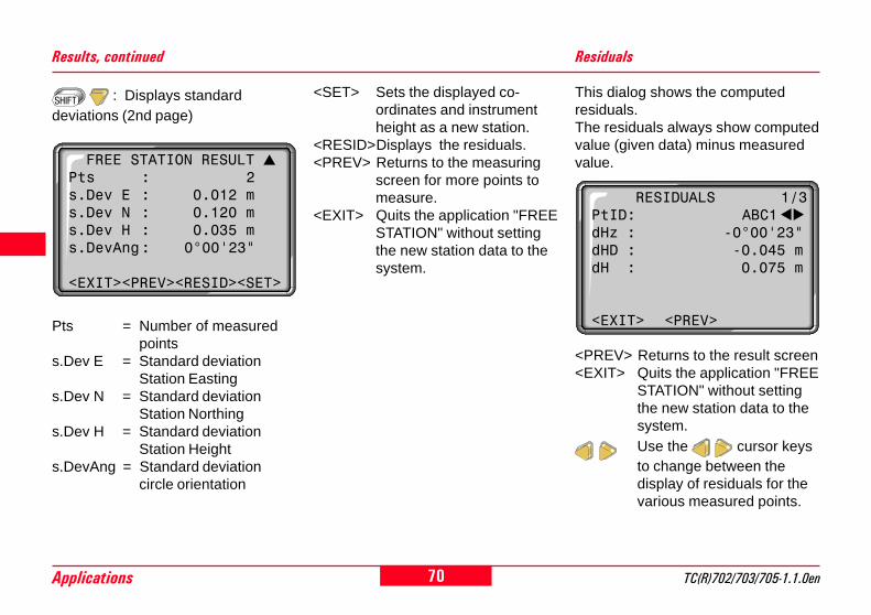
70Applications TC(R)702/703/705-1.1.0en
8
4
0
<SET> Sets the displayed co-ordinates and instrumentheight as a new station.
<RESID>Displays the residuals.<PREV> Returns to the measuring
screen for more points tomeasure.
<EXIT> Quits the application "FREESTATION" without settingthe new station data to thesystem.
Results, continued Residuals
This dialog shows the computedresiduals.The residuals always show computedvalue (given data) minus measuredvalue.
<PREV> Returns to the result screen<EXIT> Quits the application "FREE
STATION" without settingthe new station data to thesystem.Use the cursor keysto change between thedisplay of residuals for thevarious measured points.
Pts = Number of measuredpoints
s.Dev E = Standard deviationStation Easting
s.Dev N = Standard deviationStation Northing
s.Dev H = Standard deviationStation Height
s.DevAng = Standard deviationcircle orientation
: Displays standarddeviations (2nd page)
FREE STATION RESULT Pts : 2s.Dev E : 0.012 ms.Dev N : 0.120 ms.Dev H : 0.035 ms.DevAng: 0°00'23"
<EXIT><PREV><RESID><SET>
RESIDUALS 1/3PtID: ABC1dHz : -0°00'23"dHD : -0.045 mdH : 0.075 m
<EXIT> <PREV>

71TC(R)702/703/705-1.1.0en Applications
8
14
20
Error Messages
Important messages Meaning
Selected point has no valid data This message occurs if the selected target point has no easting or northingcoordinate
Max 5 points supported If already 5 points are measured and a further point is selected . The systemsupports maximum 5 points
Bad data - no position computed The measurements may not allow to compute final station coordinates (Easting,Northing)
Bad data - no height computed Either the target height are invalid or insufficient measurements are available tocompute a final station height.
Insufficient space in job The present selected job is full and does not allow further storage. This errorcould occur either with measurements or when the system stores result data,such as station results, standard deviations or residuals.
Hz (I - II) > 0.9 deg, measure pointagain
This error occurs if a point was measured in one face and the measurement inthe other face differs by more than 180° ±0.9° for the horizontal angle circle
V (I - II) > 0.9 deg, measure pointagain
This error occurs if a point was measured in one face and the measurement inthe other face differs by more than 180° ±0.9° for the vertical angle reading
More points or distance required There are insufficient data measured to be able to compute a position. Eitherthere are not enough points used or not enough distances measured.
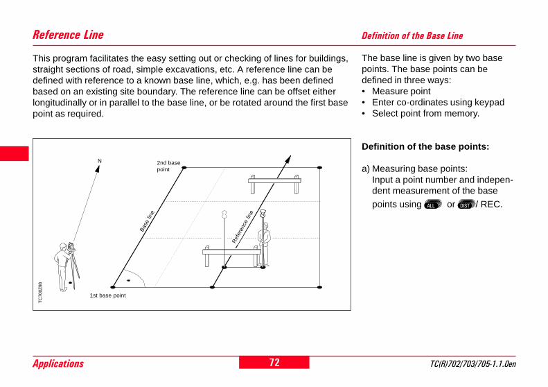
72Applications TC(R)702/703/705-1.1.0en
8
4
0
This program facilitates the easy setting out or checking of lines for buildings,straight sections of road, simple excavations, etc. A reference line can bedefined with reference to a known base line, which, e.g. has been definedbased on an existing site boundary. The reference line can be offset eitherlongitudinally or in parallel to the base line, or be rotated around the first basepoint as required.
Reference LineT
C70
0Z98
1st base point
2nd basepoint
Ref
eren
ce li
ne
Bas
e lin
e
N
Definition of the Base Line
The base line is given by two basepoints. The base points can bedefined in three ways:• Measure point• Enter co-ordinates using keypad• Select point from memory.
Definition of the base points:
a) Measuring base points:Input a point number and indepen-dent measurement of the base
points using or / REC.

73TC(R)702/703/705-1.1.0en Applications
8
14
20
Definition of the Base Line, continued
b) Base points with co-ordinates:Input a point number. The searchfor associated points in thememory can be initiated using<COORD>. If the required point isnot in memory or there are no validco-ordinates in the memory, theprogram prompts for manual entryof the co-ordinates.
Analogous procedure for the secondbase point.
<EXIT> Return to the start-upprograms.
<COORD> Input co-ordinates orsearch for fixed pointsand measurements.
<FINDPT> Activates selective pointsearch (see "PointSearch" section)
<OK> Confirms the entry andcontinues the program.
<NewL> Renewed input of thefirst base point.
Triggers a distancemeasurement.
Triggers a distancemeasurement and registerthe measured data.
Define Baseline Pt.1PtID: 101hr : 1.600 m
Hz : 236°56'14"V : 91°12'23"HD : 15.457 m<EXIT> <COORD>

74Applications TC(R)702/703/705-1.1.0en
8
4
0
1st base point
Rot+
Ref
eren
celin
e
Line
+
2nd base point
Bas
e lin
e
Referencepoint
Offs+
Input of the parameters:
Using the navigation keys / ,the focus can be moved to the offsetand rotation parameters for thereference line.
Reference Line
TC
700Z
99
The base line can be offsetlongitudinally and in parallel, as wellas rotated. This new line is called thereference line. All measured datarefers to the reference line.
Rot+: Rotation of the referenceline clockwise around thereference point.
Hoff+: Height offset; the referenceline is higher than the firstbase point.
The calculation of thereference line is performed
in stages as per the diagram shownon the left.
<EXIT> Return to the start-upprograms
<NewL> Return to the definition of anew base line
<L&O> Opens the "OrthogonalSetout" application
<RefL> Opens the "Reference Line"application
The following entries are possible:
Offs+: Parallel offset of thereference line to the right,referred to the direction ofthe base line (1-2).
Line+: Longitudinal offset of thestart point (=referencepoint) of the reference linein the direction of basepoint 2.
Define Ref.Line ShiftsPt.1 : 101Pt.2 : 102Offs: 1.000 mLine: 5.450 mRot : 20°00'00"Hoff: 0.000 m<EXIT><NewL><L&O> <RefL>

75TC(R)702/703/705-1.1.0en Applications
8
14
20
TC
700Z
102
1st base point
He
igh
t
Referenceheight
dHt-
dHt+
Hei
ght
diff.
+
<EXIT> Return to the start-upprograms
<RefL> Redefine reference line.
The height of the first reference pointis always used as the referenceheight for the calculation of heightdifferences (dHt).
Reference Line
The <RefL> function calculateslongitudinal, transverse and heightdifferences relative to the referenceline. After the first distancemeasurement, the measurementdialog displays the calculated values(dLine, dOffs, dHt) continually iftracking mode is activated.dOffs
refe
renc
e lin
e
measuredpoint
1st referencepoint
dLin
e
TC
700Z
101
Triggers a distancemeasurement.
Measures and registersmeasured data.
If tracking mode is activated(see "EDM Settings
section"), correction values for theposition of the reflector are displayedcontinuously.
1st reference point
Reference Line ResultPtID: 103hr : 1.550 m
dOffs: -0.054 mdLine: 0.020 mdHt : 0.120 m<EXIT> <RefL>

76Applications TC(R)702/703/705-1.1.0en
8
4
0
Relative to the reference line you canenter longitudinal, transverse andheight offsets for the target points tobe set-out. The program thencalculates the differences betweenthe measured point and thecalculated point. The programdisplays either the orthogonal (dL, dT,dH) or the polar differences (dHz,dHD, DH). By "making" thesedifferences as small as possible, youcan position the prism on the point tobe set-out.
Using / , you can switchbetween polar and orthogonal settingout differences.
If tracking mode is activated(see "EDM Settings"
section), correction values for theposition of the reflector are displayedcontinuously.
Orthogonal Setout
Display in measure mode:
<EXIT> Return to the start-upprograms.
<SHIFTS>Redefine reference line.<CALC> Set-out points.<L&O> Input new setting out
elements.Triggers a distancemeasurement.Triggers a distancemeasurement and registerthe measured data.
Offset input:
Example "orthogonal methods"
Offs
refe
renc
e lin
e
measuredpoint
1st referencepoint
Line
TC
700Z
100
setting outpoint
dOffs
dLin
e
dOffs: 3.750 mdLine: 10.500 mdHt : 0.350 m
Input Line & OffsetPtId: 103hr : 1.550 m
Offs: 3.750 mLine: 10.500 mHt : 1.500 m<EXIT> <SHIFTS> <CALC>
Measure Line & Offset PtId: 103hr : 1.550 m
dHz : -0°15'20"dHD : 1.220 mdH : 0.350 m<EXIT> <SHIFTS> <L&O>

77TC(R)702/703/705-1.1.0en Applications
8
14
20
The signs for the distance and angledifferences are exactly the same asfor the "Setout" application. Theseare correction values (required minusactual).
+dHz Turn telescopeclockwise to the settingout point.
+dHD The setting out point isfurther away than thepoint measured.
+dHt The setting out point ishigher than themeasured point.
Notes
Warnings/messages
Orthogonal Setout, continued
Important messages Meaning
Save via RS232 Data output (system setting menu) via RS232interface is activated. To be able to successfullystart reference line, the "IntMem" setting must beenabled.
Base line too short Base line is shorter than 1 cm. Choose basepoints such that the horizontal separation of bothpoints is at least 1 cm.
Distance not measured No distance measured or invalid.Repeat distance measurement until a validdistance is displayed.
Co-ordinates invalid No co-ordinates or invalid co-ordinates for apoint. Ensure that a point used has at least oneEasting and one Northing co-ordinate.

78Setting-Out via PC TC(R)702/703/705-1.1.0en
8
4
0
Setting-Out via PCWhen Setting-out via PC is used,data is sent from a computer (fieldcomputer, external data recordingunit) to the instrument. In general,this data is either coordinates orcalculated data, e.g. angles ordistances.
Following transmission of thenecessary data, the correspondingscreen is displayed, i.e. eithersetting-out with co-ordinates orsetting-out with azimuth, distanceand height. The subsequentprocedure for setting-out points is thesame as in the "Setting-Out"application on the instrument.
Procedure
RS232 Command
1. Open the start dialog. setout CRLFc CRLF
REMOTE SET OUT
Ready to receiveset out data...
<EXIT>
2. Input the setting-out values or the co-ordinates to be set-out.
Data Type RS232 Command
Point ID (PtID): PUT/11….+12345678_CRLFBearing (Brg): PUT/24…2+12345678_CRLFHorizontal distance (Dist): PUT/34…0+12345678_CRLFEasting co-ordinate (E): PUT/81…0+12345678_CRLFNorthing co-ordinate (N): PUT/82…0+12345678_CRLFHeight (H): PUT/83…0+12345678_CRLF
(_ = space)

79TC(R)702/703/705-1.1.0en Setting-Out via PC
8
14
20
Once the required data has beentransferred to the instrument, thedisplay changes automatically andshows the difference in the directionto the point to be set-out.
Setting-Out via PC, continued
REMOTE SET OUTPtID: 31Dist: 80.350 mdHz : 1°23'42"dHD : --------HD : --------hr : 1.500 m<EXIT>
Following the distancemeasurement, the horizon-tal distance difference andthe height difference to thepoint to be set-out aredisplayed.
Transmission of themeasured data to theexternal data recording unit.Measurements includingdata recording can also betriggered from the externaldata recording unit.
The measured data isalways transmitted over the
RS232 interface and is never writtento the internal memory in theinstrument.
Further displays
Change to further displayswith additional data inaccordance with theselected setting-outmethod:
• Setting-out with azimuth, distance,and height; change to orthogonalsetting-out (dL, dQ, dH) anddisplay of the setting-out values(PtID, Brg, Dist) and the stationdata (E0, N0, H0, hi).
• Setting-out with co-ordinates:change to orthogonal (dL, dQ, dH)or cartesian setting -out (dE, dN,dH) and display of the setting-outvalues (PtID, E, N, H, Brg, Dist).
orREC
Further commands
Inputs new data
Quits setting-outvia PC
RS232 Commands
c CRLF
x CRLF

80Coding TC(R)702/703/705-1.1.0en
8
4
0
CodingCodes contain information aboutrecorded points. With the help ofcoding, points can be assigned to aparticular group simplifying laterprocessing.
A clear differentiation is madebetween GSI-coding (TPS100instruments) and OSW-coding(TPS300/TPS700-instruments). Forfurther information regarding"Coding", please refer to section"Data Manager".
OSW-coding
Unlike the GSI-coding OSW-codingenables the division into attributenames and values.
Code: Code name
Desc.: Additional remark
Attrib.: User-defined attributename; defined whencreating the codelist.
Value: Attribute value; can beentered or edited whencalling the code.
GSI-coding
GSI codelists created with TCToolsor in T100 instruments can be used.
Code: Code name
Desc.: Additional remark
Info1: more, freely editable ... informationInfo8: lines

81TC(R)702/703/705-1.1.0en Coding
8
14
20
Coding, continuedSearching code blocks
How I can find an already enteredcode again ?Starting from "SURVEYING" thecode function can be easily called.
1. Move cursor to field "Code".
2. Enter a wildcard place holder (e.g.T*) or exact code designation and
confirm with . Code function isactivated.
CODE (Find/Select)Find: T*Code : TR1Desc : Survey_peg
<EXIT> <MAN> <ATTR><SET>
All codes corresponding to theentered search criteria are found.
<ATTR> Displays the remainingattributes.
<MAN> Starts manual code input .
Using the arrow keys, youcan page through the codesfound with entered searchcriteria.
Manual code input
Individual code blocks can beentered directly via keypad.
<MAN> Starts manual code inputand opens an empty codeblock.
Navigation and numeric/alphanumeric input possiblevia cursor keys.
Attributes 5 to 8 can be displayedwith <MORE> or .
ATTRIBUTE ENTRYCode : ------Info1: ------Info2: ------Info3: ------Info4: ------
<EXIT><PREV> <MORE><REC>
SURVEYING 1PtID : A101hr : 1.700 mCode : *Hz : 153°41'23"V : 82°12'17"HD : ----.--- m<EXIT> <QCODE>

82Coding TC(R)702/703/705-1.1.0en
8
4
0
Extending/editing code
1. Call available code from code list.
2. Attributes can be overwrittenfreely.
Exceptions:
With the codelist editor ofSurveyOffice a status can beassigned to the attributes.
• Attributes with "fixed status" (seeSurveyOffice) are write-protected.They cannot be overwritten oredited.
• For attributes with status"Mandatory" an input of aconfirmation is required.
• Attributes with status "Normal" canbe edited freely.
Call edit mode and editattribute.
Coding, continuedRecording code block
After quitting the code function with<SET> the code block in the systemis temporarily set. Recording onlywith measurement ( - or REC-fixkeys) and always with reference tothe actual point number.
Leica SurveyOfficeWith the help of the TPS-
Setup ("External Tools") theinstrument can be configured, so thatthe codes are recorded either beforeor after the measurement.
ATTRIBUTE ENTRYCode : TRBInfo1: PYLONInfo2: CONCRETEInfo3: H=1.1Info4: D=0.5
<EXIT><PREV> <MORE><SET>

83TC(R)702/703/705-1.1.0en Coding
8
14
20
Warnings / Messages
ATTRIB. CANNOT BE CHANGED> Attribute with fixed status cannot
be changed.
NO CODELIST AVAILABLE> No codelist in memory. Manual
input for code and attributes arecalled automatically.
ENTRY REQUIRED<OK>> Code missing. Extend input. One
or more attributes must be enteredor confirmed.
Coding, continuedPossible buttons<EXIT> Quits code function. Re-
turns to previous applicationor function.
<MAN> Activates the manual codeentry.
<MORE>Displays more codeattributes.
<SET> Accepts the code entry orselection and sets the codeblock in the systemtemporarily.
Individually (<MAN>)entered code blocks will not
be copied to the codelist.
Leica SurveyOfficeCodelists can be easily
created and uploaded to theinstrument using the supplied "LeicaSurveyOffice" Software.

84Coding TC(R)702/703/705-1.1.0en
8
4
0
Using the quick code function, apredefined code can be calleddirectly via the numeric keypad onthe instrument. The code is selectedby entering a two digit number, themeasurement triggered and themeasured data and code saved.A total of 100 codes can beassigned.
Each code can be assigned a uniqueone or two digit number in the LeicaSurveyOffice "Codelist Manager".The quick code function is started bytyping this number on the numerickeypad.If no numbers are allocated to thecodes in the "Codelist Manager", thecode is selected in accordance withthe order in which the codes wereentered in the code list (01 -> firstcode in the code list … 10 -> tenthcode in the code list … 00 ->hundredth (and last) code in the codelist).
Quick Code
A two digit code must alwaysbe entered on the
instrument's numeric keypad even ifonly a one digit code was assigned inthe Codelist Manager. For example:4 -> enter 04.
To activate the function the quickcode display must be opened.
Procedure
1. Press <QCODE> button in the"Measuring" or "Surveying"application.
2. Enter a two digit number on thenumeric keypad -> code isselected, the measurementtriggered and the measured dataand code saved.
The name of the selected code isdisplayed after the measurement.
It is not possible to makeany entries in the quick codedialog.
The quick code function canonly be activated in the
"Measuring" and "Surveying"applications (if there is a code list inthe memory).
QUICK CODE 1PtID : 31hr : 1.300 mCode : TREEHz : 89°23'45"V : 50°17'11"Sdist: 32.789 m<EXIT>

85TC(R)702/703/705-1.1.0en Menu
8
14
20
MenuOpens the menufunctions.
MENU1 QUICK SETTINGS2 ALL SETTINGS3 DATA MANAGER4 CALIBRATION5 SYSTEM INFO
<EXIT>
<EXIT> Leaves the menu. Back to"Measure".
Quick Settings
"Quick Settings" are settingsfrequently used integrated into acommon display. All of these settingscan also be changed in theconfiguration.The parameter or selection fields arecontrolled via the navigation keys.The current active parameter isindicated by the black bar.
Contrast:Set the display contrast in 10% steps.
Tilt Correction:Switch the compensator on or off.
USER key:Allocate function from FNC menu.
Trigger key:Configuration of trigger key located atthe side of the instrument. This canbe assigned with ALL, DIST ordeactivated.
Calling up menufunctions.
QUICK SETTINGS
Contrast : 50%Tilt Corr : 1-AxisUSER-Key : IR<=>RLTRIGGER-Key: ALL
<EXIT> <SET>
Each menu command can either bestarted directly using the appropriatedata entry key( ... ) or selected using /
and the selection confirmed using
. Only the shortcut method isreferred to in this User Manual.
Shortcut to the function"QUICK SETTINGS".
The display contents,particularly lines, contained
in this description can vary in localversions of the software. The functionof the display is however identical.

86Menu TC(R)702/703/705-1.1.0en
8
4
0
Settings System Settings
This menu enables extensive user-specific settings in order to adapt theinstrument to their own requirements.
All parameter selection fields areavailable to the user.
Displays additionalparameters.
Select a setting.
<EXIT> Back to "Settings"without setting thechanged settings.
<SET> Sets the changedsettings and returns to"Settings".
<EXIT> Leaves "Settings". Back to"Measure".
BeepThe beep is an acoustic signal aftereach key stroke.
Off Beep switched offNormal Beep switched onLoud Increased volume
Sector BeepOff: Sector beep switched off.On: Sector beep sounds at right
angles (0°, 90°, 180°, 270°or 0, 100, 200, 300 gon).
Code SetDefines whether the code block issaved before or after themeasurement (see also "Coding"section).
Before Save code block before themeasurement
After Save code block after themeasurement
Opens the menufunctions.
SETTINGS1 SYSTEM SETTING2 ANGLE SETTING3 UNIT SETTING4 EDM SETTING5 COMMUNICATION6 DATE/TIME<EXIT>
SYSTEM SETTINGS
Beep : LoudSector Beep: OffData Output: RS232AutoOFF : Enable
<EXIT> <SET>
Shortcut to the function "ALLSETTINGS".

87TC(R)702/703/705-1.1.0en Menu
8
14
20
Example Sector Beep:
From 95.0 to 99.5 gon (or from 105.0to 100.5 gon) a "Fast beep" soundswhilst from 99.5 to 99.995 gon (orfrom 100.5 to 100.995 gon) a "Per-manent beep" sounds.
Data OutputRS232 Data is recorded via the
serial interface. For thispurpose, a data storagedevice must be connected.
IntMem All data is recorded in theinternal memory.
AutoOFFEnable The instrument is switched
off after 20 minutes withoutany action (= no keypressed; V and Hz angledeviation ≤ ±3' / ±600cc).
Disable Function is deactivated andthe instrument ispermanently operating. Thebattery will not last for aslong.
Sleep Economy mode. Instrumentis recovered by any keystroke.
TC
700Z
27
1 1
1
223 3
1 No beep2 Fast beep (interrupted)3 Permanent beep
System Settings, continued
0° 180°
90°
TC
700Z
30
Contrast
10% Setting the display contrast in10% steps; adapting thereadability depending on thelight conditions.
The readability of LCDs is influencedby external conditions (temperature,lighting) and by the reading angle(see figure). The display contrast canbe adapted step by step until theoptimum readability is achieved.
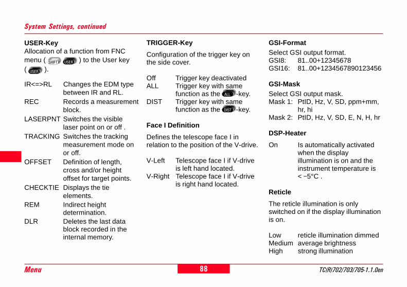
88Menu TC(R)702/703/705-1.1.0en
8
4
0
System Settings, continued
GSI-FormatSelect GSI output format.GSI8: 81..00+12345678GSI16: 81..00+1234567890123456
GSI-MaskSelect GSI output mask.Mask 1: PtID, Hz, V, SD, ppm+mm,
hr, hiMask 2: PtID, Hz, V, SD, E, N, H, hr
DSP-Heater
On Is automatically activatedwhen the displayillumination is on and theinstrument temperature is< −5°C .
Reticle
The reticle illumination is onlyswitched on if the display illuminationis on.
Low reticle illumination dimmedMedium average brightnessHigh strong illumination
USER-KeyAllocation of a function from FNCmenu ( ) to the User key( ).
IR<=>RL Changes the EDM typebetween IR and RL.
REC Records a measurementblock.
LASERPNT Switches the visiblelaser point on or off .
TRACKING Switches the trackingmeasurement mode onor off.
OFFSET Definition of length,cross and/or heightoffset for target points.
CHECKTIE Displays the tieelements.
REM Indirect heightdetermination.
DLR Deletes the last datablock recorded in theinternal memory.
TRIGGER-Key
Configuration of the trigger key onthe side cover.
Off Trigger key deactivatedALL Trigger key with same
function as the -key.DIST Trigger key with same
function as the -key.
Face I Definition
Defines the telescope face I inrelation to the position of the V-drive.
V-Left Telescope face I if V-driveis left hand located.
V-Right Telescope face I if V-driveis right hand located.

89TC(R)702/703/705-1.1.0en Menu
8
14
20
Hz-Incrementation
Hz angle incrementation
Right Set Hz to "Right anglemeasurement"(= clockwise).
Left Set Hz to "Left anglemeasurement"(= counterclockwise)."Left angle measurements"are only shown in thedisplay. They are recordedas "Right anglemeasurements" to theinternal memory.
Angle Settings
Tilt corrOff Tilt compensation switched
off.1-Axis V-angles relate to the
plumb line.2-Axis V-angles relate to plumb
line and the Hz-angles arecorrected for the tilt of thestanding axis.
If the instrument is used on anunstable base (e.g. shaking platform,ship, etc.) the compensator shouldbe switched off.This avoids the compensator driftingout of its measuring range andinterupting the measuring process byindicating an error.
ANGLE SETTINGSTilt Corr.: 1-AxisHz increm.: RightV setting : ZenithHz-collim.: OnAngle res.: 0°00'05"
<EXIT> <SET>
The compensator settingremains active even after theinstrument is switched off.

90Menu TC(R)702/703/705-1.1.0en
8
4
0
V-angles above the horizontal planeare indicated as positive values andbelow the horizontal plane as negati-ve values.
TC
700Z
29
V setting
The "0"- orientation of the vertical circle can be selected to the zenith, the horizontal plane or in %.
Angle Settings, continued
TC
700Z
28
The V-angle increases from 0° - 360°(0 - 400 gon).
100% correspond to an angle of 45°(50 gon, 800 mil).
The % value increasesrapidly. "--.--%" appears onthe display above 300%.
Zenith Horizontal plane Slope %
--.--%
--.--%
+300%
+100%
-100%
0°
+18%
-300%
45°
20°
71°3
4'
-50 gon
gon
360s± V
TC
700Z
87
-79.5 gon

91TC(R)702/703/705-1.1.0en Menu
8
14
20
Hz collimationOn Hz-collimation is switched
ON.Off Hz-collimation is switched
OFF.
If option "Hz-collimation ON" isactive, each measured Hz-angle iscorrected relative to the V-angle.
For normal operation the Hz-collimation remains switched on.
Find more information aboutthe Hz-collimation in section"Determining instrumenterrors".
Angle Settings, continued
ResolutionThe displayed angle format can beselected in three steps.
• For 360°'" :0° 00' 01" / 0° 00' 05" / 0° 00' 10"
• For 360° :TC(R)702: 0.0001° / 0.0005° /
0.0010°TC(R)703/705: 0.0005° / 0.0010° /
0.0050°
• For gon :TC(R)702: 0.0001 gon /
0.0005 gon /0.0010 gon
TC(R)703/705: 0.0005 gon /0.0010 gon /0.0050 gon
• For mil :0.01 mil / 0.05 mil / 0.10 mil

92Menu TC(R)702/703/705-1.1.0en
8
4
0
Unit Settings
Distance
meter Meterft-in1/8 US feet -inch - 1/8 inchUS-ft US feetINT-ft International feet
Temperature°C Degree Celsius°F Degree Fahrenheit
Pressurembar MillibarhPa Hecto PascalmmHg Millimeter mercury columninHg Inch mercury column
Angle
° ' " (degree sexagesimal)possible angle values:0° to 359°59'59''
dec. deg (degree decimal)possible angle values:0° to 359.999°
gon possible angle values:0 gon to 399.999 gon
mil possible angle values:0 to 6399.99mil
The setting of the angle units can bechanged at any time.The actual displayed values areconverted according to the selectedunit.
UNIT SETTINGS
Angle: gonDistance: US-ftTemp. : °FPressure: inHg
<EXIT> <SET>

93TC(R)702/703/705-1.1.0en Menu
8
14
20
EDM Settings
The EDM settings contain a detailedmenu with selection fields forrequired settings.
Dist ModeWith TCR instruments different settings for measurements with visible (RL)and invisible (IR) EDM type are available.Depending on selected measuring mode the selection prism types are diffe-rent.
With the RL-EDM each objectin the beam is measured(possibly branches, cars,etc.).
EDM SETTINGS
LaserPointer: OffEDM Mode : IR-FinePrism Type : RoundPrism Const : 0 mm
<EXIT> <PPM> <SET>
Laser PointerOff: Visible laser beam is
switched off.On: Visible laser beam for
defining the target point isswitched on.
Open second display with .
Guide Light : Off
<EXIT> <SIGNAL> <SET>
RL-Short Short range. Fordistancemeasurements withoutprisms with a targetdistance up to 80 m(3mm + 2 ppm)
RL-Track Continuous distancemeasurement withoutprisms (< 1 km)(5mm + 2 ppm)
RL-Prism Long range. Fordistancemeasurements withprisms from 1 km(5mm + 2 ppm)
IR-Fine Fine measuring modefor high precisionmeasurements withprisms(2mm + 2 ppm)
IR-Fast Quick measuring modewith higher measuringspeed and reducedaccuracy(5mm + 2 ppm)
IR-Track Continuous distancemeasuring(5mm + 2 ppm)
IR-Tape Distance measurementusing Retro targets(5mm + 2 ppm)

94Menu TC(R)702/703/705-1.1.0en
8
4
0
Leica Geosystems Prisms(Professional Series)
Constants[mm]
Leica Geosystems Prisms(Basic Series)
Standard prism GPR121
0.0
Standard prism GPR111
Miniprism GMP101/102
+17.5
Miniprism GMP111
360° PrismGRZ4
+23.1
Reflective targets +34.4
USER -- is set at "Prismconst"(Example adjacent)
RL +34.4 Reflectorless
EDM Settings, continued
Prism typeOpen the function in the EDM settings.
Prism constantOpen the function in the EDMsettings.
Entry of a user specific prismconstant. Input can only be made in[mm].
Formula:Prism constant to be entered= -mm + 34.4
Example:
Non-Leica Geosystems prismconstant = 14 mm
=>Prism constant to be entered= -14 + 34.4 = 20.4
Limit value: -999 mm to +999 mm10
0
4030
50
3886
48
2680
80
3886
48
1980
80
8660
10
10
20
30
3020
70
20
11085
45
45
18

95TC(R)702/703/705-1.1.0en Menu
8
14
20
EDM Settings, continued
1 Flashing red diode
2 Flashing yellow diode
Operating range:5 - 150 m (15 -500 ft)
Divergence:12 m (40ft) at 100m (330 ft)
Guide Light EGLThe optionally available Guide LightEGL consists of two colouredflashing lights in the telescope of thetotal station. All TC(R)702/703/705-instruments can be equipped withthis Guide Light. The person at theprism can be guided by the flashinglights directly to the line of sight. Thelight points are visible up to adistance of 150 meters. This is usefulwhen setting out points.
Off: The automatic Guide LightEGL is switched off.
On: The automatic Guide LightEGL is switched on.
Menu options are only activewhen an EGL is installed.
TC
700Z
22
2 1 TC
700Z
12
6 m(20 ft)
6 m(20 ft)
100
m (
330
ft)

96Menu TC(R)702/703/705-1.1.0en
8
4
0
EDM Settings, continued
Atmospheric Parameters (ppm)Distance measurement is influenceddirectly by the atmospheric conditionsof the air through which distancemeasurements are taken.
ATMOSPHERIC DATA
Pressure : 1013 paTemperature : 12 °C
Atmos ppm : 0Indiv ppm :<EXIT><PPM=0><PREV> <SET>
• PressureAir pressure at instrument location.
• Ht. a. MSLHeight above sea level atinstrument location.
• TemperatureAir temperature at instrumentlocation.
• Rel. Humid.Relative humidity of air in %(normally 60%)
• Refr.CoeffInput of refraction coefficient forthe atmospheric conditions.
• Atmos_ppmCalculated and indicatedatmospheric ppm.
In order to take into considerationthese influences distancemeasurements are corrected usingatmospheric correction parameters,ppm.
The atmosperic distance correctionsare derived from the air temperature,from the air pressure or the height atmean sea level and the relative airhumidity or the humidity temperature.
Ht. a. MSL : 0 mRefr. Coeff : 0.13Rel. humid. : 60 %Atmos ppm : 0

97TC(R)702/703/705-1.1.0en Menu
8
14
20
Refraction correction
The refraction correction is taken intoaccount in the calculation of theheight differences and the horizontaldistance.
Standard <PPM=0>Set all values such that the
total PPM is equal to "0" (see also"PPM Tables" in section"Atmospheric Corrections").
<SIGNAL> button
EDM SIGNAL
EDM Type: IR
60%
<EXIT> <PREV>
EDM Type:Indication of current EDM selection(infrared or reflectorless).
:Indication of EDM signal strength(reflection strength) in 1% steps.Enables optimum distancemeasurement to poorly visibletargets.
<PREV> Back to EDM settings.
EDM Settings, continued

98Menu TC(R)702/703/705-1.1.0en
8
4
0
Communication
For data transfer between PC andinstrument the communicationparameters of the serial interfaceRS232 must be set.
Leica Standard setting:19200 Baud, 8 Databit, No Parity,1 Stopbit, CR/LF
BaudrateData transfer speed 2400, 4800,9600, 19200 [bits/second]
Databits7 Data transfer is realized with 7
databits. Is set automatically ifparity is "Even" or "Odd".
8 Data transfer is realized with 8databits. Is set automatically ifparity is "None".
ParityEven Even parityOdd Odd parityNone No parity (if data bit is
set to 8)
EndmarkCR/LF Carriage return; line feedCR/LF Carriage return
StopbitsFirm setting 1.
Interface plug connections:
TC
700Z
84
1 External battery2 Not connected / inactive3 GND4 Data reception (TH_RXD)5 Data transfer (TH_TXD)
TH ... Theodolite
12
3
45
COMMUNICATIONBaudrate : 19200Datenbits: 8Parity : NoneEndmark : CR/LFStopbits : 1
<EXIT> <SET>

99TC(R)702/703/705-1.1.0en Menu
8
14
20
Date and Time
For displaying and setting of date andtime.
Time:Form: hh:mm:ss
(hours, minutes, seconds)
Date:Form: dd/mm/yyyy
(day, month, year)
/ Selects an input field.
/ Activates edit mode.
The time/date is immediately set forthe complete system after input.
SET DATE/TIME
Time(24h): 12:15:07Date : 29/02/2000
<OK>
Adjustable Date Adjustable Time

100Menu TC(R)702/703/705-1.1.0en
8
4
0
Data Manager
The Data Manager contains allfunctions for entering, editing andchecking data in the field.
Open the menufunctions.
Shortcut to the function"DATA MANAGER".
VIEW / EDIT DATA
<EXIT> Back to Data Manager.
Direct selection of the datatype.
Select data type usingarrow keys.
Opens Data Manager.
VIEW / EDIT DATA
1 JOB2 FIXPOINT3 MEASUREMENT4 CODELIST
<EXIT>
• VIEW / EDIT DATAEdit, create, view and delete jobs,measurements, fixed points andcodelists.
• INITIALIZE MEMORYDelete complete memory,individual jobs or complete dataareas (e.g. fixed points,measurements).
• DATA DOWNLOADSelected data sets are transferedto the interface without protocoland test procedures.
• MEMORY STATISTICStatistical information about joband memory allocation.
Shortcut to the function"VIEW / EDIT DATA" in the"Data Manager" display.
DATA MANAGER
1 VIEW / EDIT DATA2 INITIALIZE MEMORY3 DATA DOWNLOAD4 MEMORY STATISTIC
<EXIT>
..

101TC(R)702/703/705-1.1.0en Menu
8
14
20
VIEW / EDIT DATA, continued
Job search:
Using the arrow keys the joblist can be paged through inboth directions.
Deleting job:
Select relevant job.
<DEL> Deletes all data within a job.
Job
Jobs are a summary of data ofdifferent types, e.g. fixed points,measurements, codes, results, etc.
The job definition consists of theinput of job name and user.Additionally, the system generatestime and date at the time of creation.
VIEW JOB 1/2
Job : Project_01COper: T.WaitsDate: 16/06/98Time: 09:30:11
<EXIT> <DEL> <NEW>
Input of a Job:
<NEW> Defines a new job and jobdata entry (e.g. job, user).
<SAVE> Creates and registers thenew job.
<PREV> Back to job search withoutsaving.

102Menu TC(R)702/703/705-1.1.0en
8
4
0
VIEW / EDIT DATA, continued
Fixed points
Fixed points may be entered withpoint number, coordinates (E, N) andheight.
VIEW FIXPOINTJob: Project_01CFind: *PtID: ABC1E : 31798003.234 mN : 15635975.915 mH : 8723.001 m<EXIT> <DEL> <NEW>
Measurements
Measurement data available in theinternal memory can be searchedand displayed or deleted.
Enter fixed points:
<NEW> Starts the point and editinput for fixed points orediting of existing fixedpoints by calling the rele-vant point number.
Within the job selectionfield the directory for thefixed point is selected.
<SAVE> Saves the data entered.
<PREV> Back to fixed point searchor display of coordinates.
Fixed point search:
The same conditions are valid hereas with point search. You can enterthe exact point number or limit thedata range by entering a wildcard(e.g. A*).
Input of a search criteria for points.
Selection fieldfor job.
Valid fixed points contain a minimumof one point number and either theco-ordinates (E, N) or the height (H).
<DEL> Deletes the selected fixedpoint.
VIEW MEASUREMENT(Set Data Search)
Job: Projekt_01CPtID : A*
<EXIT> <VIEW>

103TC(R)702/703/705-1.1.0en Menu
8
14
20
VIEW / EDIT DATA, continued
Points can be searched for by twomethods:
• Job selection:(e.g. "Project_01C")
• Point selection:Finds all points meeting theconditions mentioned above andalso the search critera for the pointsearch.
e.g. If "A*" is entered, all data forwhich the point ID starts with "A" isfound.
Extended display withco-ordinates and timeinformation.
<DEL> Deletes the selecteddata set from theinternal memory.
<SEARCH> Back to point search.
Additional data blocks canbe recorded in the
measuring range irrespective of theprogram in use.
Corrections:EDM-Type, EDM-Mode, Prism typ,Prism constant, Atmospheric PPM,Pressure, Ht. Above Sea Level,Temperature, Rel. humid., RefractionCoefficient
Stations:PtID, E, N, H, hi, Date, Time
Results:No pts, StDev. Hz, Date, Time, Area,Tie Distance, setout differences, etc.
Measurements :Pt, Hz, V, SD, Hd, dH, hr, E, N, H,Date, Time
Codes:Code, Rem., Attr.1-8
You will find detailedinformation on the storage of
data in the section "Saving Data".
VIEW 35Type : MeasurementPtID : A412Hz : 125°13'00"V : 92°45'12"H0 : 113.405 mhr : 1.500 m<EXIT> <DEL> <SEARCH>

104Menu TC(R)702/703/705-1.1.0en
8
4
0
VIEW / EDIT DATA, continued
Codelist
To each code a description and amaximum of 8 attributes with up to 16characters can be assigned.
VIEW CODELISTFind: Nr*Code: Nr01Desc: Border lineInfo1: Nr.123Info2: 12.54Info3: 5.20<EXIT> <DEL> <NEW>
<NEW> : Enter new codelist:
Input of a new code and a descriptivetext.
INPUT CODELIST
Code: Nr01Desc: Border line
<EXIT><PREV><ATTR><SAVE>
<ATTR> Input of attributes(alphanumeric).
<SAVE> Records inputs; back tocode search.
<PREV> Back to code search;without saving.
Deleting code:
Select relevant code.
<DEL> Deletes code block.
Extended display forviewing and checkingattributes.
Code can be searched directly, eitherwith the code name or wildcard (*).
Searching for code:
The codelist can be toggledthrough in both directionsusing the arrow keys .

105TC(R)702/703/705-1.1.0en Menu
8
14
20
Delete Memory
Individual jobs or complete dataareas of a job are deleted. Deletingall data in memory.Two selection fields enable a specificarea to be selected.
Shortcut to the function"INITIALIZE MEMORY" in the"Data Manager" display. Clearing all data
in database '
<NO> <YES>
<NO> Back to selection of area tobe deleted. Data is kept.
<YES> Deletes the selected dataarea within the selected job.
Deleting the memory cannotbe undone. After confirming
the message all data is deletedpermanently.
INITIALIZE MEMORY
Job : Project_04BData: Measurements
<EXIT> <ALLMEM> <DEL>
Selection of job and dataarea to be deleted.
Possible data areas:• measurements• fixed points• jobs
<DEL> Starts deleting processwithin the selected area.
<ALLMEM>Deletes all data inmemory. All data will belost !

106Menu TC(R)702/703/705-1.1.0en
8
4
0
With this special function measureddata can be transfered via the serialinterface to a receiver (e.g. aLaptop). The success of the transferis not checked when this type of datatransfer is used.
Shortcut to the function"DATA DOWNLOAD" in the"Data Manager" display.
Data Download
Job: Selection of job from whichdata should be transfered.
Data: Fixed points ormeasurements can be sentseparately andindependently from eachother. Selection of datatype.
Format: Select output format.The following formats canbe selected for output:1. GSI2. APA CAD3. User-defined data formatsUser-defined formats mustbe first loaded using LeicaSurvey Office (Data Ex-change Manager).
Selection of individualparameters.
<SEND> Data is sent via interface.
Example: "GSI" format
Within the "data" setting"MEASUREMENTS", a data setcould have the following appearance:
11....+00000D19 21.022+1664182622.022+09635023 31..00+0000664958..16+00000344 81..00+0000334282..00-00005736 83..00+0000009187..10+00001700 522.16-00000000
If the receiver is too slow inprocessing data the data
could be lost. With this type of datatransfer the instrument is notinformed about the performance ofthe receiver (no protocol).
DATA DOWNLOAD
Job : Project_04BData: MeasurementsForm: EASI
<EXIT> <SEND>

107TC(R)702/703/705-1.1.0en Menu
8
14
20
Statistics
It is possible for the user to call-upimportant information about thestatus of the internal memory.Additionally, the user can obtaininformation about the composition ofthe data in the individual jobs.
Stations :Number of stations used within theselected jobs.
Fixpoints :Number of stored fixed points withinthe selected jobs.
Meas Recs :Number of recorded data blocks(measured points, codes, etc.) withinthe selected jobs.
Free Jobs :Number of free or not defined jobs.<EXIT> Back to Data Manager.
MEMORY INFORMATIONJob :Project_04BStations : 18Fixpoints: 372MeasRecs : 2534
Free Jobs : 1<EXIT>
Shortcut to the function"MEMORY STATISTIC" in the"Data Manager" display.

108Menu TC(R)702/703/705-1.1.0en
8
4
0
Messages and Warnings
Messages
Data SAVED• Data has been recorded in the
internal memory.> Display disappears after <1
seconds. Back to last activedisplay.
Data DELETED• Data has been deleted in the
internal memory.> Display disappears after <1
seconds. Back to last activedisplay.
JOB DELETED• The content of a complete job has
been deleted permanently.> Display disappears after <1
seconds. Back to last activedisplay.
Warnings
No data found in memory!• No relevant data blocks could be
found in the memory.> Search for other data or enter
relevant data in the Data Manager.Confirm with <OK>. Back to lastactive display.
Error messages
All memory blocks occupied!!• Available memory full.> Delete a job or data area in the
internal memory. Confirmmessage with <OK>.
Job already exists in database!!• Job or job name already exists in
memory.> Change job name. Make sure that
the job name is not alreadyavailable. Confirm message with<OK>.
Invalid Job-Name!!• Job name is empty or contains a
"-".> Change job name. Confirm
message with <OK>.
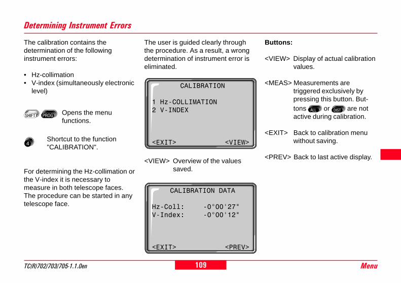
109TC(R)702/703/705-1.1.0en Menu
8
14
20
Determining Instrument Errors
The calibration contains thedetermination of the followinginstrument errors:
• Hz-collimation• V-index (simultaneously electronic
level)
The user is guided clearly throughthe procedure. As a result, a wrongdetermination of instrument error iseliminated.
CALIBRATION DATA
Hz-Coll: -0°00'27"V-Index: -0°00'12"
<EXIT> <PREV>
Buttons:
<VIEW> Display of actual calibrationvalues.
<MEAS> Measurements aretriggered exclusively bypressing this button. But-tons or are notactive during calibration.
<EXIT> Back to calibration menuwithout saving.
<PREV> Back to last active display.
Opens the menufunctions.
<VIEW> Overview of the valuessaved.
Shortcut to the function"CALIBRATION".
For determining the Hz-collimation orthe V-index it is necessary tomeasure in both telescope faces.The procedure can be started in anytelescope face.
CALIBRATION
1 Hz-COLLIMATION2 V-INDEX
<EXIT> <VIEW>

110Menu TC(R)702/703/705-1.1.0en
8
4
0
The vertical circle should readexactly 90° (100 gon) when the lineof sight is horizontal. Any deviationfrom this figure is termed verticalindex error (i).
By determining the vertical indexerror the electronic level is adjustedautomatically.
V-Index (Vertical Index Error)
TC
700Z
13
i
Line-Of-Sight Error (Hz-Collimation)
The line-of-sight error or collimationerror (C) is the deviation from theperpendicular between the tilting axisand the line of sight.
The effect of the line-of-sight error tothe Hz-angle increases with thevertical angle.For horizontal aimings the error ofthe Hzangle equals the line-of-sighterror.
TC
700Z
16
cThe instruments are adjusted in thefactory prior to shipping.
Instrument errors can change withtime and temperature.
These errors should bedetermined before the
instrument is used for the first time,before precision surveys, after longperiods of transport, before and afterlong periods of work, and if thetemperature changes by more than10°C (18°F).
Before determining theinstrument errors, level-upthe instrument using the
electronic bubble. The instrumentshould be secure and firm, andshould be protected from directsunlight in order to avoid thermalwarming on one side only.

111TC(R)702/703/705-1.1.0en Menu
8
14
20
Determining The Line-Of-Sight Error (c)
TC
700Z
17
ca. 100 m
± 4°30'
1. Level up instrument exactly usingthe electronic level.
2. Aim at a point approximately 100mfrom the instrument that is lessthan ± 4°30' (5 gon) from thehorizontal.
3. <MEAS> Trigger measurement.
4. Change telescope face and aim onpoint again.
TC
700Z
18
180°
180°
6. Indication of previous andrecomputed line-of-sight-error.
The new value can be eitheraccepted with <SET> or rejected with<EXIT>.
HZ-COLLIMATION 1
Hz : 123°43'07"V : 272°11'31"
Sight target !
<EXIT> <MEAS>
For checking the horiontal aiming Hzand V are displayed.
5. <MEAS> Trigger measurementagain.
HZ-COLLIMATION 2
Hz : 303°43'17"V : 87°48'19"dHz: -0°00'10"dV : 0°00'28"
<EXIT> <MEAS>
HZ-COLLIMATION (c)
c(old): -0°00'27"c(new): -0°00'25"

112Menu TC(R)702/703/705-1.1.0en
8
4
0
1. Level up instrument exactly usingthe electronic level.
2. Aim at a point approximately 100mfrom the instrument that is lessthan ± 4°30' (5 gon) from thehorizontal.
3. <MEAS> Trigger measurement.
4. Change telescope position andaim on point again.
6. Indication of previous andrecomputed V-index.
The new value can be eitheraccepted with <SET> or rejected with<EXIT>.
VERTICAL INDEX 1
Hz : 123°43'07"V : 272°11'31"
Sight target !
<EXIT> <MEAS>
For checking the horiontal aiming Hzand V are displayed.
5. <MEAS> Trigger measurementagain.
VERTICAL INDEX 2
Hz : 303°43'17"V : 87°48'19"dHz: -0°00'10"dV : 0°00'28"
<EXIT> <MEAS>
VERTICAL INDEX (i)
i(old): -0°00'27"i(new): -0°00'14"
By determining the verticalindex error the electroniclevel is adjustedautomatically.
Determining V-Index
TC
700Z
17
ca. 100 m
TC
700Z
18
180°
180°
± 4°30'

113TC(R)702/703/705-1.1.0en Menu
8
14
20
Possible Messages when Determining Instrument Errors
Important messages Meaning Measures
V-Angle not suitable forcalibration (Check V-angle or face)
Aiming tolerance not met or telescope facenot changed.
Aim on the target point with an accuracy ofmin. 5 gon. The target point must beapproximately in the horizontal plane.Confirmation of the message required.
Calibration result out oftolerance. Previousvalues retained
Computed values out of tolerance. Previousvalues retained.
Repeat measurements.Confirmation of the message required.
Hz-Angle out of limit Hz-angle in second face deviates more than5 gon from the target point.
Aim on the target point with an accuracy ofmin. 5 gon.Confirmation of the message required.
Measurement Error. Tryagain.
Measurement error appeared (e.g. instableset up or period between measuring intelescope face I and II too long).
Repeat the process.Confirmation of the message required.

114Menu TC(R)702/703/705-1.1.0en
8
4
0
System Information
IR<=>RL Switches between IRand RL.
REC Records a measurementblock
LASERPNT Switches on or off thevisible laser point.
TRACKING Switches on or off thetracking measurementmode.
OFFSET Definition of length,cross and/or heightoffset for target points.
CHECKTIE Displays the tieelements.
REM Indirect heightdetermination.
DLR Deletes the last datablock recorded in theinternal memory.
Free JobsNumber of free jobs is displayed. Ifno jobs are in the memory under"Measure and Record" the systemcreates a "Default" job automatically.All data is stored into this Default jobwhich can be freely renamed.
Tilt Corr.Display of current compensatorsetting:Off: Compensator switched off.1-Axis: Compensator activated in
longitudinal axis along thedirection to the target).
2-Axis: Compensator activated inlongitudinal and transverseaxis
USER-KeyCurrent assignment of the -key.The following functions from the FNCmenu are available:
Useful information which can becalled via menu. These are onlyindications of actual setting andcannot be changed here. All changesto settings must be carried out inmenu "SETTINGS".
Opens the menufunctions.
Shortcut to the function"SYSTEM INFO".
Scrolls the display.
<SW> Software versions overview.

115TC(R)702/703/705-1.1.0en Menu
8
14
20
TRIGGER-KeyOff: function deactivated.ALL: ALL function activated.DIST: DIST function activated.
BatteryRemaining battery power (e.g. 40%).
Instr.Temp.Measured instrument temperature.
DSP Heater (On/Off)Activates the display heating. Withsetting ON the heating is switched onas soon as the instrumenttemperature falls below "-5°C" andthe illumination is switched off.When the temperature increasesagain, the heating is automaticallyswitched off.
System Information, continued
Software versionsThe software of the instrument iscomposed of different softwarepackages. Depending on thispackages different versions arepossible.Op-System: Operating SystemAppl.-SW: Applications, functions
and menuLayout: User displays
Hz-Coll. (On/Off)The correction of measured Hz-angles with the Hz collimation can beswitched On/Off.
Calibration ValuesIndication of last determined andstored calibration values(Hz-collimation, V-index).

116Saving Data TC(R)702/703/705-1.1.0en
8
4
0
Saving DataThe following categories of data arestored in the internal memory:• Measured data• Fixed points• Jobs
The measured data are subdividedinto different objects (measurements,target points, stations, results,residuals, correction parameters,codes). Depending on theapplication, one or more of theseobjects are saved, the contents(attributes) of the objects aredescribed in the following. The timeand date are also saved at the sametime with each object, as well as thename of the application in which theobjects were saved.
Comment on the "Measurement"object:E, N, H, HD and dH are calculatedfrom the measurements (applies toall applications).
Job
Job = Job nameOper = Observer nameRem1 = Comment 1Rem2 = Comment 2Date = DateTime = Time
Start-Up Programs
Station
Stn = Station numberE0 = Station co-ordinate (Easting)N0 = Station co-ordinate (Northing)H0 = Station heighthi = Instrument height
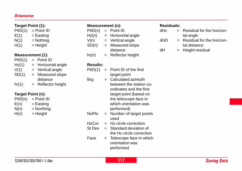
117TC(R)702/703/705-1.1.0en Saving Data
8
14
20
Target Point (1):PtID(1) = Point IDE(1) = EastingN(1) = NothingH(1) = Height
Measurement (1):PtID(1) = Point IDHz(1) = Horizontal angleV(1) = Vertical angleSD(1) = Measured slope
distancehr(1) = Reflector height
Target Point (n):PtID(n) = Point IDE(n) = EastingN(n) = NorthingH(n) = Height
Orientation
Measurement (n):PtID(n) = Point IDHz(n) = Horizontal angleV(n) = Vertical angleSD(n) = Measured slope
distancehr(n) = Reflector height
Results:PtID(1) = Point ID of the first
target pointBrg = Calculated azimuth
between the station co-ordinates and the firsttarget point (based onthe telescope face inwhich orientation wasperformed)
NoPts = Number of target pointsused
HzCor = Hz circle correctionSt Dev = Standard deviation of
the Hz circle correctionFace = Telescope face in which
orientation wasperformed
Residuals:dHz = Residual for the horizon-
tal angledHD = Residual for the horizon-
tal distancedH = Height residual

118Saving Data TC(R)702/703/705-1.1.0en
8
4
0
Applications
Measuring Application
Measurement:
PtID = Point IDHz = Horizontal angleV = Vertical angleSD = Measured slope distancehr = Reflector height
Measurement:
PtID = Point IDHz = Horizontal angleV = Vertical angleSD = Measured slope distancehr = Reflector height
Target Point:PtID = Point IDE = EastingN = NorthingH = Height
Measurement:PtID = Point IDHz = Horizontal angleV = Vertical angleSD = Measured slope distancehr = Reflector height
Results:dE = Easting setting-out
difference between targetand measured point
dN = Northing setting-outdifference between targetand measured point
dH = Height setting-outdifference between targetand measured point
Survey Application Setting-Out Application

119TC(R)702/703/705-1.1.0en Saving Data
8
14
20
Measurement (1):PtID(1) = Point IDHz(1) = Horizontal angleV(1) = Vertical angleSD(1) = Measured slope distancehr(1) = Reflector height
Measurement (n):PtID(n) = Point IDHz(n) = Horizontal angleV(n) = Vertical angleSD(n) = Measured slope distancehr(n) = Reflector height
Results:NoPts = Number of pointsArea = AreaPerim. = Perimeter of area
Area Application
Target Point (1):PtID(1) = Point IDE(1) = EastingN(1) = NorthingH(1) = Height
Measurement (1):PtID(1) = Point IDHz(1) = Horizontal angleV(1) = Vertical angleSD(1) = Measured slope distancehr(1) = Reflector height
Target Point (n):PtID(n) = Point IDE(n) = EastingN(n) = NorthingH(n) = Height
Free Station Application
Measurement (1):PtID(1) = Point IDHz(1) = Horizontal angleV(1) = Vertical angleSD(1) = Measured slope distancehr(1) = Reflector height
Measurement (n):PtID(n) = Point IDHz(n) = Horizontal angleV(n) = Vertical angleSD(n) = Measured slope distancehr(n) = Reflector height
Results (n-1) - (n):SD = Slope distanceHD = Horizontal distancedH = Height differenceBrg = Azimuth
Tie Distance Application

120Saving Data TC(R)702/703/705-1.1.0en
8
4
0
Measurement (n):PtID(n) = Point IDHz(n) = Horizontal angleV(n) = Vertical angleSD(n) = Measured slope distancehr(n) = Reflector height
Station results:Stn = Station numberE = Station co-ordinate (Easting)N = Station co-ordinate (Northing)H = Station heighthi = Instrument height
Standard deviations:StDv(E) = Standard deviation of the
station co-ordinates(Easting)
StDv(N) = Standard deviation of thestation co-ordinates(Northing)
StDv(H) = Standard deviation of thestation height
StDv(P) = Average point positionerror=
Free Station Application, continued
Residuals:dHz = Residual on the horizon-
tal angledHD = Residual on the horizon-
tal distancedH = Height residual
Orientation point (1):PtID(1) = Point IDE(1) = EastingN(1) = NorthingH(1) = Height
Orientation measurement (1):PtID(1) = Point IDHz(1) = Measured horizontal
angle + orientationunknowns
V(1) = Vertical angleSD(1) = Measured slope
distancehr(1) = Reflector height
Orientation results:PtID(1) = Point ID of the first
target pointBrg = Calculated azimuth
between the station co-ordinates and the firsttarget point (based onthe telescope face inwhich orientation wasperformed)
NoPts = Number of target pointsused
HzCor = Hz circle correctionStDev = Standard deviation of
the Hz circle correctionFace = Telescope face in which
orientation wasperformed
22 )()( NmFEmF +

121TC(R)702/703/705-1.1.0en Saving Data
8
14
20
• Reference lineMeasurement (1):PtID = Point IDHz = Horizontal angleV = Vertical angleHD = Measured slope distancehr = Reflector heightTarget Point (1):PtID = Point IDE = EastingN = NorthingH = HeightMeasurement (2):PtID = Point IDHz = Horizontal angleV = Vertical angleHD = Measured slope distancehr = Reflector heightTarget Point (2):PtID = Point IDE = EastingN = NorthingH = HeightTransformation Parameters:Line = Longitudinal offsetOffs = Parallel offsetHoff = Height offsetRot = Rotation
Reference Line Application
• Reference LineMeasurement:PtID = Point IDHz = Horizontal angleV = Vertical angleHD = Slope distancehr = Reflector height
Results:dLine = Longitudinal offset with
respect to reference pointOffs = Transverse offset with
respect to reference pointdHt = Height offset with respect
to reference point
• Orthogonal setting outOrthogonal setting out elements:PtID = Point IDLine = Longitudinal valueOffs = Transverse valueHt = Height value
Measurement:PtID = Point IDHz = Horizontal angleV = Vertical angleHD = Slope distancehr = Reflector height
Results:Line = Longitudinal difference
required - actualdOffs = Transverse difference
required - actualdHt = Height difference required -
actual

122Saving Data TC(R)702/703/705-1.1.0en
8
4
0
Correction Parameters
A correction block is stored everytime when:• a new job is stored or• one or more parameters are
changed in the EDM settings in theinstrument (see list below).
EDM
EDM typeEDM modePrism typePrism constants
Atmospheric Corrections
Pressure = Air pressureTemperature= TemperatureRel. humid. = Relative atmospheric
humidityRefr. Coeff. = Coefficient of
refractionHt. a. MSL = Height above see
levelAtmos ppm = Atmospheric PPM
Functions
Determination of the Height of RemotePoints
Measurement (1):PtID(1) = Point IDHz(1) = Horizontal angleV(1) = Vertical angleSD(1) = Measured slope distancehr(1) = Reflector height
Measurement (n):PtID(n) = Point IDHz(n) = Horizontal angleV(n) = Vertical angleSD(n) = Measured slope distancehr(n) = Reflector height
Results (n-1) - (n):dH = Height difference
Target Offset
L_Offset = Length offsetT_Offset = Cross offsetH_Offset = Height offset

123TC(R)702/703/705-1.1.0en Saving Data
8
14
20
Coding
OSW-Coding
Code = Name of codeDesc = CommentAttr1 = Attribute name 1Attr2 = Attribute name 2Attr3 = Attribute name 3Attr4 = Attribute name 4Attr5 = Attribute name 5Attr6 = Attribute name 6Attr7 = Attribute name 7Attr8 = Attribute name 8
GSI-Coding
Code = Name of codeDesc = CommentInfo1 = Information 1Info2 = Information 2Info3 = Information 3Info4 = Information 4Info5 = Information 5Info6 = Information 6Info7 = Information 7Info8 = Information 8
Fixed Points (Coordinates)
PtID = Point IDE = EastingN = NorthingH = Height
RS232
Measurements (PtID, Hz, V, SD, hr)are output over the RS232 serialinterface if data output over RS232 isset.
No results or othercalculated data (e.g. HD) is
output over the RS232 serialinterface.
The type of data output (internalmemory or RS232) is set in the menu(see MENU / SYSTEM INFO).

124Safety Directions TC(R)702/703/705-1.1.0en
8
4
0
Safety DirectionsThe following directions shouldenable the person responsible for theTC(R)702/703/705, and the personwho actually uses the instrument, toanticipate and avoid operationalhazards.
The person responsible for theinstrument must ensure that all usersunderstand these directions andadheres to them.
Permitted Uses
The electronic total stations areintended to the following applications:
• Measuring horizontal and verticalangles
• Measuring distances
• Recording measurements
• Computing by means ofapplication software
• Visualising the standing axis (withlaser plummet)
Intended Use of Instrument
Adverse Uses
• Use of the total station withoutprevious instruction
• Use outside of the intended limits• Disabling safety systems and rem-
oval of hazard notices• Opening the instrument using tools
(screwdriver, etc.), unless this isspecifically permitted for certainfunctions
• Modification or conversion of theinstrument
• Use after misappropriation• Use with accessories from other
manufacturers without the priorexpress approval of LeicaGeosystems
• Aiming directly into the sun• Inadequate safeguards at the
surveying site (e.g. whenmeasuring on roads, etc.)

125TC(R)702/703/705-1.1.0en Safety Directions
8
14
20
Limits of Use
Refer to section "Technical Data".
Environment:Suitable for use in an atmosphereappropriate for permanent humanhabitation: not suitable for use in ag-gressive or explosive environments.Use in rain is permissible for limitedperiods.
Temperature limits
Responsibilities
Area of responsibility for themanufacturer of the originalequipment Leica Geosystems AG,CH-9435 Heerbrugg(hereinafter referred to as LeicaGeosystems):Leica Geosystems is responsible forsupplying the product, including theUser Manual and originalaccessories, in a completely safecondition.
Responsibilities of themanufacturers of non-Leica Geo-systems accessories:
The manufacturers of non-Leica Geosystems
accessories for the TC(R)702/703/705 electronic total stations areresponsible for developing,implementing and communicatingsafety concepts for their products,and are also responsible for theeffectiveness of those safetyconcepts in combination with the Lei-ca Geosystems product.
• Controlling machines, orcontrolling moving objects orsimilar, with the integrated EDM(visible laser)
• Deliberate dazzling of third parties
WARNING:
Adverse use can lead toinjury, malfunction, and
material damage.It is the task of the personresponsible for the instrument toinform the user about hazards andhow to counteract them. Theelectronic total stations are not to beused until the user has been properlyinstructed how to use them.
Adverse Uses, continued
+50
0
-20
+122
0
-4 -40
+158
-40
0 0
TC
700Z
60
°F °C °F °C

126Safety Directions TC(R)702/703/705-1.1.0en
8
4
0
Responsibilities of the person incharge of the instrument:
WARNING:The person responsible forthe instrument must ensure
that it is used in accordance with theinstructions. This person is alsoaccountable for the training anddeployment of personnel who use theinstrument and for the safety of theequipment when in use.
The person in charge of theinstrument has the following duties:
• To understand the safetyinstructions on the product and theinstructions in the User Manual.
• To be familiar with local regulationsrelating to accident prevention.
• To inform Leica Geosystemsimmediately if the equipmentbecomes unsafe.
Hazards of Use
WARNING:The absence of instruction,or the inadequate imparting
of instruction, can lead to incorrect oradverse use, and can give rise toaccidents with far-reaching human,material, financial and environmentalconsequences.Precautions:All users must follow the safetydirections given by the manufacturerand the directions of the personresponsible for the instrument.
WARNING:The battery charger is notdesigned for use under wet
and severe conditions. If instrumentbecomes wet it may cause you toreceive an electric shock.Precautions:Use charger only in dry rooms andprotect instrument from humidity. Donot use instruments in a wetenvironment.

127TC(R)702/703/705-1.1.0en Safety Directions
8
14
20
DANGER:Because of the risk ofelectrocution, it is very
dangerous to use reflector poles andextensions in the vicinity of electricalinstallations such as power cables orelectrical railways.Precautions:Keep at a safe distance fromelectrical installations. If it is essentialto work in this environment, firstcontact the safety authoritiesresponsible for the electricalinstallations and follow theirinstructions.
Hazards of Use, continued
WARNING:If you open the charger,either of the following
actions may cause you to receive anelectric shock:• Touching live components• Using the charger after incorrect
attempts to carry out repairsPrecautions:Do not open the charger. Only a Lei-ca Geosystems-approved servicetechnician is entitled to repair it.
WARNING:By surveying during athunderstorm you are at risk
from lightening.Precautions:Do not carry out field surveys duringthunderstorms.
CAUTION:
Be careful not to point theinstrument directly towards
the sun, because the telescopefunctions as a magnifying lens andcan injure your eyes or damage thedistance measuring device and theGuide Light EGL.Precautions:Do not point the telescope directly atthe sun.

128Safety Directions TC(R)702/703/705-1.1.0en
8
4
0
WARNING:If computers intended foruse indoors are used in the
field there is a danger of electricshock.
Precautions:
Adhere to the instructions given bythe computer manufacturer withregard to field use in conjunction withLeica Geosystems instruments.
Hazards of Use, continued
WARNING:During target recognition orstakeout procedures there is
a danger of accidents occurring if theuser does not pay attention to the en-vironmental conditions (e.g.obstacles, excavations or traffic).Precautions:The person responsible for theinstrument must make all users fullyaware of the existing dangers.
WARNING:
Inadequate securing of thesurveying site can lead to
dangerous situations, for example intraffic, on building sites and atindustrial installations.Precautions:Always ensure that the surveying siteis adequately secured. Adhere to thelocal regulations governing accidentprevention and road traffic.
CAUTION:If a target lamp accessory isused with the instrument the
lamp's surface temperature may beextreme after a long working period.It may cause pain if touched.Replacing the halogen bulb beforethe lamp has been allowed to cooldown may cause burning to the skinor fingers.Precautions:Use appropriate heat protection suchas gloves or woollen cloth beforetouching the lamp, or allow the lampto cool down first.

129TC(R)702/703/705-1.1.0en Safety Directions
8
14
20
Hazards of Use, continued
WARNING:If the equipment isimproperly disposed of, the
following can happen:• If polymer parts are burnt,
poisonous gases are producedwhich may impair health.
• If batteries are damaged or areheated strongly, they can explodeand cause poisoning, burning,corrosion or environmentalcontamination.
• By disposing of the equipmentirresponsibly you may enableunauthorized persons to use it incontravention of the regulations,exposing themselves and thirdparties to the risk of severe injuryand rendering the environmentliable to contamination.
• Leakage of silicone oil from thecompensator can damage theoptical and electronicsubassemblies.
Precautions:Dispose of the equipmentappropriately in accordance with theregulations in force in your country.Always prevent access to theequipment by unauthorizedpersonnel.
CAUTION:During the transport ordisposal of charged batteries
it is possible for inappropriatemechanical influences to constitute afire hazard.Precautions:Before transporting or disposing ofequipment, discharge the battery(e.g. by running the instrument intracking mode until the batteries areexhausted).

130Safety Directions TC(R)702/703/705-1.1.0en
8
4
0
Laser Classification
CAUTION:Allow only authorized LeicaGeosystems service
workshops to service the instrument.
Hazards of Use, continued
CAUTION:Watch out for erroneousmeasurements if the
instrument is defective or if it hasbeen dropped or has been misusedor modified.Precautions:Periodically carry out testmeasurements and perform the fieldadjustments indicated in the UserManual particularly after theinstrument has been subjected to ab-normal use and before and afterimportant measurements.
CAUTION:If the accessories used withthe instrument are not
properly secured, and the equipmentis subjected to mechanical shock(e.g. blows, falling etc.), theequipment may be damaged, safetydevices may be ineffective or peoplemay sustain injury.Precautions:When setting-up the instrument,make sure that the accessories (e.g.tripod, tribrach, etc.) are correctlyadapted, fitted, secured and locked inposition.Avoid subjecting the equipment tomechanical shock.Never position the instrument on thetripod baseplate without securelytightening the central fixing screw. Ifthe screw is loosened always removethe instrument immediately from thetripod.
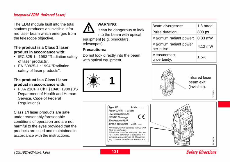
131TC(R)702/703/705-1.1.0en Safety Directions
8
14
20
The EDM module built into the totalstations produces an invisible infra-red laser beam which emerges fromthe telescope objective.
The product is a Class 1 laserproduct in accordance with:• IEC 825-1 : 1993 "Radiation safety
of laser products".• EN 60825-1 : 1994 "Radiation
safety of laser products".
The product is a Class I laserproduct in accordance with:• FDA 21CFR Ch.I §1040: 1988 (US
Department of Health and HumanService, Code of FederalRegulations)
Class 1/I laser products are safeunder reasonably foreseeableconditions of operation and are notharmful to the eyes provided that theproducts are used and maintained inaccordance with the instructions.
Integrated EDM (Infrared Laser)
WARNING:It can be dangerous to lookinto the beam with optical
equipment (e.g. binoculars,telescopes)
Precautions:
Do not look directly into the beamwith optical equipment.
TC70
0Z54
Type: TC.... Art.No.: ......Power: 12V/6V ---, 1A maxLeica Geosystems AGCH-9435 HeerbruggManufactured:1998Made in Switzerland S.No.: ......This laser product complies with 21CFR1040 as applicable.This device complies with part 15 of theFCC Rules. Operation is subject to thefollowing two conditions: (1) This devicemay not cause harm-ful interference, and
1
TC70
0Z11
Infrared laserbeam exit(invisible).
Beam divergence: 1.8 mrad
Pulse duration: 800 ps
Maximum radiant power: 0.33 mW
Maximum radiant powerper pulse:
4.12 mW
Measurementuncertainty:
± 5%

132Safety Directions TC(R)702/703/705-1.1.0en
8
4
0
Integrated EDM (Visible Laser)
As an alternative to the infraredbeam, the EDM incorporated into thetotal station produces a visible redlaser beam which emerges from thetelescope objective.The product is a Class 2 laserproduct in accordance with:• IEC 825-1 : 1993 "Radiation safety
of laser products".• EN 60825-1 : 1994 "Radiation
safety of laser products".
The product is a Class II laserproduct in accordance with:• FDA 21CFR Ch.I §1040: 1988 (US
Department of Health and HumanService, Code of FederalRegulations)
Class 2/II laser products:Do not stare into the beam or direct itunnecessarily at other persons. Eyeprotection is normally afforded byaversion responses including theblink reflex.
WARNING:It can be dangerous to lookinto the beam with optical
equipment (e.g. binoculars,telescopes)
Precautions:
Do not look directly into the beamwith optical equipment.
Labelling
A V O ID EX P O SU R ELaser rad iation is em itted from this ap ertu re
Type: TC.... Art.No.: ......Power: 12V/6V ---, 1A maxLeica Geosystems AGCH-9435 HeerbruggManufactured:1998Made in Switzerland S.No.: ......This laser product complies with 21CFR 1040as applicable.This device complies with part 15 of the FCCRules. Operation is subject to the following twoconditions: (1) This device may not cause harm-ful interference, and (2) this device must acceptany interference received, including inter-ference that may cause undesired operation.
LASER RADIATION - DO NOT
620-690nm/0.95mW max.CLASS II LASER PRODUCT
STARE INTO BEAM
2 1/4s
TC
700Z
53
Emitted W avelenght :
M ax. em itted Power :
Standar d appl ied :
0.95mW c.w .
620-690nm
EN60825-1 : 1994- 07
IEC825-1 : 1993- 11
Max. emitted Power : 0.95mW
Emitted Wavelength : 620-690nm
Standard applied : EN60825-1:1994-07
IEC825-1 : 1993-11

133TC(R)702/703/705-1.1.0en Safety Directions
8
14
20
TC70
0Z11
The integrated Guide Light producesa visible LED beam from the upperfront side of the telescope.The product is a Class 1 LED product*) in accordance with:• IEC 825-1: 1993 "Radiation safety
of laser products"• EN 60825-1: 1994 "Radiation
safety of laser products"
*) Within the specified working rangeof > 5 m (> 16 ft).
Class 1 LED products are safe underreasonably foreseeable conditions ofoperation and are not harmful to theeyes provided that the products areused and maintained in accordancewith the instructions.
CAUTION:
Use the Guide Light onlywithin the specified working
range of > 5 m (> 16 ft) from thetelescope.
Guide Light EGL
1 Exit for flashing red LED2 Exit for flashing yellow LED
Integrated EDM, continued
TC
300z
22
12
Exit for laserbeam(visible).
Beam divergence: 0.15 x 0.35 mrad
Pulse duration: 800 ps
Maximum radiantpower:
0.95 mW
Maximum radiantpower per pulse:
12 mW
Measurementuncertainty:
± 5%
1
Flashing LED yellow red
Beam divergence: 2.4 ° 2.4 °
Pulse duration: 2 x 10⁵ ms 1 x 10⁵ ms
Maximum radiantpower:
0.28 mW 0.47 mW
Maximum radiantpower per pulse:
0.75 mW 2.5 mW
Measurementuncertainty:
± 5 % ± 5 %

134Safety Directions TC(R)702/703/705-1.1.0en
8
4
0
The integrated laser plummetproduces a visible laser beam whichemerges from the base of theinstrument.
The product is a Class 2 laserproduct in accordance with:• IEC 825-1 : 1993 "Radiation safety
of laser products".• EN 60825-1 : 1994 "Radiation
safety of laser products".
The product is a Class II laserproduct in accordance with:• FDA 21CFR Ch.I §1040: 1988 (US
Department of Health and HumanService, Code of FederalRegulations)
Class 2/II laser products:Do not stare into the beam or direct itunnecessarily at other persons. Eyeprotection is normally afforded byaversion responses including theblink reflex.
Laser Plummet
Labelling
Emitted W avelenght :
M ax. em itted Power :
Standar d appl ied :
0.95mW c.w .
620-690nm
EN60825-1 : 1994- 07
IEC825-1 : 1993- 11
Max. emitted Power : 0.95mW c.w.
Emitted Wavelength : 620-690nm
Standard applied : EN60825-1:1994-07
IEC825-1 : 1993-11
TC
700Z
55
Type: TC.... Art.No.: ......Power: 12V/6V ---, 1A maxLeica Geosystems AGCH-9435 HeerbruggManufactured:1998Made in Switzerland S.No.: ......This laser product complies with 21CFR 1040as applicable.This device complies with part 15 of the FCCRules. Operation is subject to the following twoconditions: (1) This device may not cause harm-ful interference, and (2) this device must acceptany interference received, including inter-ference that may cause undesired operation.
LASER RADIATION - DO NOT
620-690nm/0.95mW max.CLASS II LASER PRODUCT
STARE INTO BEAM
2 1/4s
A V O ID EX P O SU R ELaser rad iation is em itted from this ap ertu re

135TC(R)702/703/705-1.1.0en Safety Directions
8
14
20
Laser beam (visible)
Infrared laser beamexit (invisible).
TC
700Z
56
Electromagnetic Compatibility (EMC)
The term "electromagneticcompatibility" is taken to mean thecapability of the instrument tofunction correctly in an environmentwhere electromagnetic radiation andelectrostatic discharges are present,and without causing electromagneticdisturbances in other equipment.
Laser Plummet, continued
WARNING:Electromagnetic radiationcan cause disturbances inother equipment.
Although electronic total stationsmeet the strict regulations andstandards which are in force in thisrespect, Leica Geosystems cannotcompletely exclude the possibilitythat other equipment may bedisturbed.
Beam divergence: 0.16 x 0.6 mrad
Pulse duration: c.w.
Maximum radiantpower:
0.95 mW
Maximum radiantpower per pulse:
n/a
Measurementuncertainty:
± 5%

136Safety Directions TC(R)702/703/705-1.1.0en
8
4
0
Electromagnetic Compatibility (EMC), continued
CAUTION:There is a risk thatdisturbances may be caused
in other equipment if the total stationis used in conjunction withaccessories from othermanufacturers, e.g. field computers,personal computers, walkie-talkies,non-standard cables, externalbatteries.Precautions:Use only the equipment andaccessories recommended by LeicaGeosystems. When combined withtotal stations, they meet the strictrequirements stipulated by theguidelines and standards. Whenusing computers and walkie-talkies,pay attention to the information aboutelectromagnetic compatibilityprovided by the manufacturer.
CAUTION:Disturbances caused byelectromagnetic radiation
can result in the tolerance limits formeasurements being exceeded.
Although the total stations meet thestrict regulations and standardswhich are in force in this connection,Leica Geosystems cannot completelyexclude the possibility that the totalstation may be disturbed by veryintense electromagnetic radiation,e.g. near radio transmitters, walkie-talkies, diesel generators, powercables.Check the plausibility of resultsobtained under these conditions.
WARNING:If the total station is operatedwith connecting cables
attached at only one of their two ends(e.g. external supply cables, interfacecables), the permitted level ofelectromagnetic radiation may beexceeded and the correct functioningof other instruments may beimpaired.
Precautions:
While the total station is in use,connecting cables (e.g. instrument toexternal battery, instrument tocomputer) must be connected at bothends.

137TC(R)702/703/705-1.1.0en Safety Directions
8
14
20
FCC Statement (Applicable in U.S.)
WARNING:This equipment has been tested and found tocomply with the limits for a Class B digital
device, pursuant to part 15 of the FCC Rules.These limits are designed to provide reasonableprotection against harmful interference in a residentialinstallation.This equipment generates, uses and can radiatefrequency energy and, if not installed and used inaccordance with the instructions, may cause harmfulinterference to radio communications.However, there is no guarantee that interference will notoccur in a particular installation.
If this equipment does cause harmful interference toradio or television reception, which can be determined byturning the equipment off and on, the user is encouragedto try to correct the interference by one or more of thefollowing measures:• Reorient or relocate the receiving antenna.• Increase the separation between the equipment and
receiver.• Connect the equipment into an outlet on a circuit diffe-
rent from that to which the receiver is connected.• Consult the dealer or an experienced radio/TV
technician for help.
WARNING:
Changes or modifications not expresslyapproved by Leica Geosystems for compliancecould void the user's authority to operate theequipment.
Product labelling:
This device complies with part 15 of the FCCRules. Operation is subject to the following twoconditions: (1) This device may not cause harm-ful interference, and (2) this device must acceptany interference received, including inter-ference that may cause undesired operation.
TC
700Z
54
Type: TC.... Art.No.: ......Power: 12V/6V ---, 1A maxLeica Geosystems AGCH-9435 HeerbruggManufactured:1998Made in Switzerland S.No.: ......This laser product complies with 21CFR 1040as applicable.This device complies with part 15 of the FCCRules. Operation is subject to the following twoconditions: (1) This device may not cause harm-ful interference, and (2) this device must acceptany interference received, including inter-ference that may cause undesired operation.

138Care and Storage TC(R)702/703/705-1.1.0en
8
4
0
TC
700Z
21
TC
700Z
36
When transporting or shipping theequipment always use the originalLeica Geosystems packaging(transport case and shippingcardboard).
After a longer period ofstorage or transport of yourinstrument always check thefield ajustment parametersindicated in this manualbefore using the instrument.
Transport In the Field
• carry the tripod with its legssplayed across your shoulder,keeping the attached instrumentupright.
When transporting the equipment inthe field , always make sure to
• either carry the instrument in itsoriginal transport case or,
Care and Storage

139TC(R)702/703/705-1.1.0en Care and Storage
8
14
20
TC
700Z
70
TC
700Z
71
TC
700Z
61 °F °C
Never transport the instrument looseinside the vehicle .The instrument can be damaged byblows and vibrations. It must alwaysbe transported in its case and beproperly secured.
Storage
When storing the equipment,particularly in summer and
inside a vehicle, take thetemperature limits into account.
When storing the intrument inside abuilding also use the transport case(if possible, in a safe place).
Inside Vehicle Shipping
For shipping the instrument by rail,aircraft or ship use the Leica Geosy-stems original packaging (transportcase or shipping cardboard) oranother suitable packaging securingthe instrument against blows andvibrations.

140Care and Storage TC(R)702/703/705-1.1.0en
8
4
0
Cleaning
If the instrument becomeswet, leave it unpacked.
Wipe down, clean, and dry theinstrument (at not more than 40 °C/108°F), transport case, foam inserts,and accessories. Pack up theequipment only when it is perfectlydry.
When using the instrument in thefield always close the transport case.
Objective, eyepiece andprisms:
• Blow dust off lenses and prisms.• Never touch the glass with fingers.• Use only a clean, soft and lint-free
cloth for cleaning. If necessary,moisten the cloth with purealcohol.
Use no other liquids; these mayattack polymer components.
Fogging of prisms:Reflector prisms that are
cooler than the ambient temperaturetend to fog. It is not enough simply towipe them. Keep them for some timeinside your jacket or in the vehicle toallow them to adjust to the ambienttemperature.
Cables and plugsKeep plugs clean and dry.
Blow away any dirt lodged in theplugs of the connecting cables.
TC
700Z
66
TC
700Z
50
TC
700Z
67

141TC(R)702/703/705-1.1.0en Care and Storage
8
14
20
1 2
TC
700Z
44
TC
700Z
43
TC
700Z
45
Checking and Adjusting
Level-up the instrument in advancewith the electronic level. The bubblemust be centered. If it extendsbeyond the circle, use the Allen keysupplied to center it by turning theadjustment screws.
After adjustment no screw must beloose.
Circular Level
Level the instrument and thenremove it from the tribrach. If thebubble is not centred, adjust it usingthe adjusting pin.Turning the adjustment screws:• to the left: the bubble approaches
the screw• to the right: the bubble goes away
from the screw.
After adjustment no screw must beloose.
Circular Level on the Tribrach
The connections between metal andtimber components must always befirm and tight.• Tighten the Allen screws (2)
moderately.• Tighten the articulated joints on the
tripod head (1) just enough to keepthe tripod legs open when you lift itoff the ground.
Tripod

142Care and Storage TC(R)702/703/705-1.1.0en
8
4
0
2
360°
± 0.8 mm / 1.5 m
1
TC
700Z
20
Laser spot:Ø 2.5 mm / 1.5 m
Laser Plummet
The laser plummet is integrated intothe vertical axis of the instrument.Under normal circumstances settingof the laser plummet is notnecessary. If an adjustment isnecessary due to external influencesthe instrument has to be returned toany Leica service department.
Checking by turning theinstrument by 360°:1. Install the instrument on the tripod
approx. 1.5 m above ground andlevel up.
2. Switch on laser plummet and markthe centre of the red spot.
3. Turn instrument slowly by 360°and observe the red laser spot.
Inspecting the laser plummet shouldbe carried out on a bright, smoothand horizonal surface (e.g. a sheet ofpaper).
If the centre of the laser spot makesa clearly circular movement or if thecentre of the point is moving awaymore than 1mm from the first markedpoint an adjustment is possiblynecessary. Call your nearest Leicaservice department.
Depending on brightness and surfacethe size of the laser spot can vary. Ata distance of 1.5 m an average valueof 2.5 mm diameter must beestimated.
The maximum diameter of thecircular movement of the centre ofthe laser spot should not exceed +/-0.8 mm at a distance of 1.5 m.

143TC(R)702/703/705-1.1.0en Care and Storage
8
14
20
TC
700Z
88
Reflectorless EDM
The red laser beam used formeasuring without reflector isarranged coaxially with the line ofsight of the telescope, and emergesfrom the objective port. If theinstrument is well adjusted, the redmeasuring beam will coincide withthe visual line of sight. Externalinfluences such as shock or largetemperature fluctuations can displacethe red measuring beam relative tothe line of sight.
The direction of the beamshould be inspected before
precise measurement of distances isattempted, because an excessivedeviation of the laser beam from theline of sight can result in imprecisedistance measurements.
Inspection
A target plate is provided. Set it upbetween five and 20 metres awaywith the grey reflective side facing theinstrument. Move the telescope toface II. Switch on the red laser beamby activating the laser-point function.Use the telescope crosshair to alignthe instrument with the centre of thetarget plate, and then inspect theposition of the red laser spot on thetarget plate. Generally speaking thered spot cannot be seen through thetelescope, so look at the target platefrom just above the telescope or fromjust to the side of it.If the spot illuminates the cross, theachievable adjustment precision hasbeen reached; if it lies outside thelimits of the cross, the direction of thebeam needs to be adjusted.
If the spot on the more reflective sideof the plate is too bright (dazzling),use the white side instead to carryout the inspection.

144Care and Storage TC(R)702/703/705-1.1.0en
8
4
0
TC
700Z
51
TC
700Z
52
Adjusting the Direction of the Beam
Pull the two plugs out from theadjustment ports on the top side ofthe telescope housing.To correct the height of the beam,insert the screwdriver into the rearadjustment port and turn it clockwise(spot on target plate moves obliquelyupwards) or anticlockwise (spotmoves obliquely downwards).To correct the beam laterally, insertthe screwdriver into the frontadjustment port and turn it clockwise(spot moves to the right) oranticlockwise (spot moves to theleft).
Reflectorless EDM, continued
Throughout the adjustmentprocedure, keep the
telescope pointing to the target plate.
After each field adjustment,replace the plugs in the
adjustment ports to keep out dampand dirt.

145TC(R)702/703/705-1.1.0en Technical Data
8
14
20
Technical DataAngle measurement• absolute, continuous,• Updates each 0.3 seconds• Units selectable
360° sexagesimal, 400gon,360° decimal, 6400 mil, V%, ±V
• Standard deviation(acc. to DIN 18723 / ISO 12857)TC(R)702 2" (0.6 mgon)TC(R)703 3" (1 mgon)TC(R)705 5" (1.5 mgon)
• Smallest display resolutiongon: TC(R)702 0.0001
TC(R)703/705 0.0005360d: TC(R)702 0.0001
TC(R)703/705 0.0005360s: 1"mil: 0.01
Level sensitivity• Circular level: 6'/2 mm• Electronic bubble: 20"/2mm
Telescope• Transits fully• Magnification: 30x
• Image: upright
• Free objective aperture: 40 mm
• Shortest focussingdistance: 1.7 m (5.6 ft)
• Focusing: fine
• Field of view: 1°30' (1.7gon)
• Telescope field of view at100m 2.6 m
Laser plummet :• In alidade, turns with instrument• Accuracy: max. rot. diameter of
laser spot: ± 0.8 mm / 1.5m• Diameter of laser spot:
2.5 mm / 1.5m
Compensator :• 2-axis-oil compensator• Setting range ±4' (0.07 gon)• Setting accuracy
TC(R)702 0.5" (0.2 mgon)TC(R)703 1" (0.3 mgon)TC(R)705 1.5" (0.5 mgon)
Keyboard :• Tilt angle: 70°• Base area: 110x75 mm• No. of buttons: 24 plus ON
and trigger key(on side cover)
Display:• Backlit• Heatable (Temp. < -5°C)• LCD: 144x64 Pixel• 8 lines with 24 characters each

146Technical Data TC(R)702/703/705-1.1.0en
8
4
0
Tilting axis height:• without tribrach 196 mm• with tribrach GDF111
240 mm ± 5 mm• with tribrach GDF121
238 mm ± 5 mm
Power supply :• Battery GEB111: NiMh
(0% Cadmium)Voltage: 6V, 1800 mAh
• Battery GEB121: NiMh(0% Cadmium)
Voltage: 6V, 3600 mAh• Battery adapter GAD39:
6 x LR6/AA/AM3, 1.5V,only alkaline batteries
• External supply(via serial interface)
If an external cable is used,then the voltage range must liebetween 11.5VDC and 14VDC.
Type of tribrach :• Tribrach removable GDF111/
GDF121Thread diam.: 5/8"
(DIN 18720 / BS 84)
Dimensions :• Instrument:
Height (including tribrach andcarrying handle):- with tribrach GDF111
360 mm ± 5 mm- with tribrach GDF121
358 mm ± 5 mmWidth: 150 mmLength: 145 mm
• Case: 468x254x355mm(LxBxH)
Weight:(including battery GEB111 andtribrach)• with tribrach GDF111 5.33 kg• with tribrach GDF121 5.52 kg
Technical Data, continuedNumber of measurements :GEB111:• Angle: >4 h• Distance: > 1000GEB121:• Angle: >8 h• Distance: > 2000
Temperature range :• Storage: -40°C to +70°C
-40°F to +158°F• Operating: -20°C to +50°C
-4°F to +122°F
Automatic corrections:• Line-of-sight error Yes• Vertical-index error Yes• Earth curvature Yes• Refraction Yes• Tilt correction Yes
Recording:• RS232 interface Yes• Internal memory: Yes
Total capacity 288 KB≈ 4500 data blocks and
≈ 7000 fixed points

147TC(R)702/703/705-1.1.0en Technical Data
8
14
20
Standardprism
3 prisms(GPH3)
360°reflector
Tape60mm x60mm
Mini-prism
11800 m(6000 ft)
2300 m(7500 ft)
800 m(2600 ft)
150 m(500 ft)
800 m(2600 ft)
23000 m
(10000 ft)4500 m
(14700 ft)1500 m(5000 ft)
250 m(800 ft)
1200 m(4000 ft)
33500 m
(12000 ft)5400 m
(17700 ft)2000 m(7000 ft)
250 m(800 ft)
2000 m(7000 ft)
Distance measurement (RL: visible)• Type visible red laser• Carrier wavelength 0.670 µm• Measuring system special frequency system
basis 100 MHz = 1.5 m• EDM type coaxial• Display (least count) 1 mm• Laser spot size: approx. 7x 14 mm / 20 m
approx. 10 x 20 mm / 50 m
Technical Data, continuedDistance measurement (IR: infrared)• Type infrared• Carrier wavelength 0.780 µm• Measuring system special frequency system
basis 100 MHz = 1.5 m• EDM type coaxial• Display (least count) 1 mm
1) Strong haze, visibility 5km; or strong sunlight, severe heatshimmer
2) Light haze, visibility about 20km; or moderate sunlight,slight heat shimmer
3) Overcast, no haze, visibility about 40km; no heat shimmer
* Beam interruptions, severe heat shimmer and movingobjects within the beam path can result in deviations from thespecified accuracy.
Range:(normal and rapid measurement)
EDM measuringprogram
Accuracy *Time per
measurement
Standardmeasurement
2 mm + 2 ppm <1 sec.
Fast measurement 5 mm + 2 ppm <0.5 sec.
Tracking 5 mm + 2 ppm <0.3 sec.
IR Tape 5 mm + 2 ppm <0.5 sec.

148Technical Data TC(R)702/703/705-1.1.0en
8
4
0
Atmosphericconditions
Standard prism(GPR1)
Three prisms(GPH3)
1 1500 m (5000 ft) 2000 m (7000 ft)
2 5000 m (16000 ft) 7000 m (23000 ft)
3 > 5000 m (16000 ft) > 9000 m (30000 ft)
Atmosphericconditions
No reflector(white target)*
No reflector(grey, albedo 0.25)
4 60 m (200 ft) 30 m (100 ft)
5 80 m (260 ft) 50 m (160 ft)
6 80 m (260 ft) 50 m (160 ft)
EDM measuringprogram
Accuracy ** Time per measurement
Short 3 mm + 2 ppm3.0 sec.
+1.0 sec./10m > 30m
Prism 5 mm + 2 ppm 2.5 sec.
Tracking 5 mm + 2 ppm1.0 sec.
+0.3 sec./10m > 30m
Technical Data, continued
Distance measurement (with reflector)• Range of measurement: from 1000m up• Display unambiguous: to 12 km
* Kodak Grey Card used with exposure meter for reflectedlight
4) Object in strong sunlight, severe heat shimmer5) Object in shade, or sky overcast6) Day, night and twilight
Range (with reflector)
Range (without reflector)
1) Strong haze, visibility 5km; or strong sunlight, severe heatshimmer
2) Light haze, visibility about 20km; or moderate sunlight,slight heat shimmer
3) Overcast, no haze, visibility about 40km; no heat shimmer
Distance measurement (reflectorless)• Range of measurement: 1.5 m to 80 m
(to target plate 710 333)• Display unambiguous: to 760 m• Prism constant (additive constant): + 34.4 mm
** Beam interruptions, severe heat shimmer and movingobjects within the beam path can result in deviations from thespecified accuracy.

149TC(R)702/703/705-1.1.0en Corrections and Formulae
8
14
20
Corrections and Formulae
The distance displayed is correct onlyif the scale correction in ppm (mm/km) which has been enteredcorresponds to the atmosphericconditions prevailing at the time ofthe measurement.
The atmospheric correction includesadjustments for air pressure, airtemperature and relative humidity.
If, for highest-precision distancemeasurements, the atmosphericcorrection should be determined withan accuracy of 1 ppm, the followingparameters must be redetermined:Air temperature to 1°C; air pressureto 3 millibars; relative humidity to20%.
The air humidity influences thedistance measurement if the climateis extremely hot and damp.
For high-precision measurements,the relative humidity must bemeasured and entered along with theair pressure and the temperature.
Atmospheric Correction
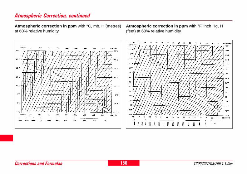
150Corrections and Formulae TC(R)702/703/705-1.1.0en
8
4
0
Atmospheric Correction, continued
Atmospheric correction in ppm with °C, mb, H (metres)at 60% relative humidity
Atmospheric correction in ppm with °F, inch Hg, H(feet) at 60% relative humidity

151TC(R)702/703/705-1.1.0en Corrections and Formulae
8
14
20
Reduction Formulae
= displayed slope distance [m]D0 = uncorrected distance [m]ppm = scale correction [mm/km]mm = prism constant [mm]
= D0 · (1 + ppm · 10-6) + mm
The instrument calculates slopedistance, horizontal distance andheight difference in accordance withthe following formula. Earth curvatureand mean refraction coefficient (k =0.13) are taken into accountautomatically. The calculated hori-zontal distance relates to the stationheight, not to the reflector height.
Reflector
Mean sea level
Height measurement
Instrument
ζ
TC
700Z
97

152Accessories TC(R)702/703/705-1.1.0en
8
4
0
AccessoriesLeica Geosystems offers two accessory sets that ease the user's choice from the range of accessories offered by Lei-ca Geosystems. The existing accessories continue to be available.
TC
700Z
49
Standard Accessory Set
Tribrach GDF111 BASIC
Battery GEB111 (2x)
Battery charger GKL111 BASIC
Data cable Lemo0/RS232
Extended Accessory Set
Tribrach GDF121 PRO
Battery GEB121 (2x)
Battery charger GKL122 PRO
Data cable Lemo0/RS232

153TC(R)702/703/705-1.1.0en Index
8
14
20
Index
360° Prism GRZ4 ........................................................... 94
A Abbreviations ................................................................. 10Accessories .................................................................. 152Accuracy ............................................................. 147, 148Accurate Levelling-Up .................................................... 29Adapter GKL23 .............................................................. 24Adapter plate (GDI121) .................................................. 24Adjusting the Direction of the Beam ............................ 144Alphanumeric Character Set ......................................... 34Alphanumeric Values ..................................................... 32Angle .............................................................................. 92Angle measurement ..................................................... 145Angle Settings ................................................................ 89Applications ........................................................... 54, 118Area Computation .......................................................... 63Atmos_ppm .................................................................... 96Atmospheric Correction ............................................... 149Atmospheric Parameters (ppm) .................................... 96Automatic corrections .................................................. 146AutoOFF ......................................................................... 87
B Base line ........................................................................ 72Base point ............................................................... 45, 72Basic battery (GEB111) .................................................. 21Batteries ......................................................................... 21Battery .......................................................................... 115Battery adapter GAD39 ............................................ 9, 21Battery charger ....................................................... 20, 22
Battery Charger GKL122 .............................................. 24Battery Charger GKL111 ................................................ 22Battery charger GKL111 BASIC ................................... 152Battery charger GKL122 PRO ..................................... 152Battery GEB111 ....................................................... 9, 152Battery GEB111/GEB121 ............................................... 22Battery GEB121 ...................................................... 9, 152Battery holder for GEB111/GEB121/GAD39 ................... 9Battery spacer for GEB111 .............................................. 9Baudrate ......................................................................... 98Beep ............................................................................... 86Button functions ............................................................. 54Buttons .................................................................... 15, 17
C CALIBRATION.............................................................. 109Calibration Values ........................................................ 115Care and Storage......................................................... 138Carrying handle ................................................................ 9Cartesian Setout ............................................................ 57Centring with Laser Plummet ........................................ 28Centring with Shifting Tribrach ...................................... 30Check Tie ....................................................................... 44Checking and Adjusting ............................................... 141Circular Level ............................................................... 141Circular level .................................................................... 9Circular Level on the Tribrach ..................................... 141Cleaning ....................................................................... 140Coarse Level-Up ............................................................ 28Codelist ........................................................................ 104Codelist Manager ........................................................... 13Coding ................................................................... 80, 123

154Index TC(R)702/703/705-1.1.0en
8
4
0
Index, continuedCommunication .............................................................. 98Compensator ................................................................ 145Computation Procedure ................................................. 67Computed Orientation .................................................... 53Contrast ................................................................... 85, 87Coordinate Editor ........................................................... 13Correction Parameters ................................................. 122Corrections and Formulae ........................................... 149Counterweight for eyepiece for steep angles................ 20Cursor ............................................................... 31, 32, 33
D Data .............................................................................. 106Data cable Lemo0/RS232 .................................... 20, 152DATA DOWNLOAD ...................................................... 100Data Download............................................................. 106Data entry keys ....................................................... 14, 16Data entry mode ............................................................ 32Data Exchange Manager ............................................... 13Data Manager .............................................................. 100Data Output .................................................................... 87Databits .......................................................................... 98Date ................................................................................ 99Date and Time ................................................................ 99Delete Last Record ........................................................ 46Delete Memory ............................................................. 105Deleting code ............................................................... 104Deleting job .................................................................. 101Deleting Letters/Numbers .............................................. 33Determining Instrument Errors .................................... 109
Determining The Line-Of-Sight Error (c) ......................111Determining V-Index .................................................... 112Dimensions .................................................................. 146Display ..................................................................... 9, 145Dist Mode ....................................................................... 93Distance ......................................................................... 92Distance measurement .................................................. 38Distance measurement (IR: infrared) ......................... 147Distance measurement (reflectorless) ........................ 148Distance measurement (RL: visible) ........................... 147Distance measurement (with reflector) ....................... 148DSP-Heater .................................................................... 88
E Edit mode ......................................................... 31, 32, 33EDM Change .................................................................. 41EDM measuring program .................................... 147, 148EDM Settings ................................................................. 93EDM SIGNAL ................................................................. 97Electromagnetic Compatibility (EMC) ............................ 26Electromagnetic Compatibility (EMC) .......................... 135Electronic Level .............................................................. 29Endmark ......................................................................... 98Enter fixed points ......................................................... 102Enter new codelist ........................................................ 104Extended Accessory Set .............................................. 152Extending/editing code .................................................. 82External Power Supply ................................................... 26External Tools ................................................................. 13

155TC(R)702/703/705-1.1.0en Index
8
14
20
Index, continued
F Face I Definition ............................................................. 88Fixed keys ............................................................... 14, 15Fixed keys - 2nd level .................................................... 14Fixed point search ........................................................ 102Fixed points .................................................................. 102Fixed Points (Coordinates) .......................................... 123Fixpoint .................................................................... 35, 37Fixpoints ....................................................................... 107FNC Key ......................................................................... 41FNC menu ...................................................................... 41Focus bar ....................................................................... 14Foot screws ...................................................................... 9Format .......................................................................... 106Free Jobs ............................................................ 107, 114Free Station .................................................................... 65Functions ...................................................................... 122
G GSI-coding ..................................................................... 80GSI-Format .................................................................... 88GSI-format .................................................................... 106GSI-Mask ....................................................................... 88Guide Light EGL ................................................... 95, 133
H Hazards of Use ............................................................ 126Height Determination Of Remote Points ....................... 45Height Transfer .............................................................. 50Horizontal angle ............................................................. 10Horizontal circle ............................................................. 10Horizontal drive ................................................................ 9Horizontal plane ............................................................. 90
Ht. a. MSL ...................................................................... 96Hz collimation ................................................................. 91Hz-Coll. (On/Off) .......................................................... 115Hz-Collimation .............................................................. 110Hz-Incrementation .......................................................... 89Hz0 ................................................................................. 38
I Important Components .................................................... 9INITIALIZE MEMORY .................................................. 100Input of a Job ............................................................... 101Inserting / Replacing Battery ......................................... 25Inserting Characters/Numbers ...................................... 32Inside Vehicle ............................................................... 139Inspection ..................................................................... 143Instrument Temperature ............................................... 115Integrated EDM (Visible Laser) .................................. 132Integrated EDM (Infrared Laser) .................................. 131Integrated guide light EGL ............................................... 9Intended Use of Instrument ......................................... 124IR-Fast ............................................................................ 93IR-Fine ............................................................................ 93IR-Tape ........................................................................... 93IR-Track .......................................................................... 93
J Job ....................................................................... 101, 106Job search .................................................................... 101
K Key combinations ........................................................... 15Keyboard ...................................................................... 145Keypad ...................................................................... 9, 14

156Index TC(R)702/703/705-1.1.0en
8
4
0
Index, continued
L Laser Classification ...................................................... 130Laser Intensity ................................................................ 29Laser Plummet .................................................... 134, 142Laser plummet ............................................................. 145Laser Pointer ........................................................... 42, 93Laser spot size ............................................................. 147Leica Standard setting ................................................... 98Leica SurveyOffice .................................................. 13, 82Lens hood ...................................................................... 20Level sensitivity ............................................................ 145Limits of Use ................................................................ 125Line & Offset .................................................................. 77Line of sight / collimation axis ........................................ 10Line-of-sight error (Hz-collimation) ................................ 11Line-Of-Sight Errors ..................................................... 110
M Mains adapter for battery ............................................... 20Manual code input .......................................................... 81Manual Input of Setting Out Values ............................... 56Manual input of the station coordinates ........................ 40Meas Recs ................................................................... 107Measurement .......................................................... 35, 37Measurements ............................................................. 102Measuring ...................................................................... 38MEMORY STATISTIC .................................................. 100Menu............................................................................... 85Menu Tree ...................................................................... 19Messages and Warnings ............................................. 108Mini prism ....................................................................... 20Mini prism GMP 111 ....................................................... 94
Mini prism GMP101/102 ................................................ 94Mini prism rod ................................................................. 20
N Navigation keys ....................................................... 14, 16Number of measurements ........................................... 146Numeric Character Set .................................................. 34Numeric Values .............................................................. 31
O Objective .......................................................................... 9On/Off key ........................................................................ 9Opening an menu item .................................................. 19Operating the Instrument ............................................... 14Optical sight ..................................................................... 9Orientation ............................................................... 39, 51Orthogonal Setout ................................................... 57, 76OSW-coding ................................................................... 80
P Parity .............................................................................. 98Plug connections ........................................................... 98Plumb line / Compensator ............................................. 11Point Search ................................................................... 35Polar Setout ................................................................... 57Polygonal Methods ........................................................ 60Positioning...................................................................... 30Power supply ................................................................ 146Pressure .................................................................. 92, 96Prism constant ............................................................... 94Prism type ...................................................................... 94Pro battery (GEB121) .................................................... 21Protective cover ............................................................. 20

157TC(R)702/703/705-1.1.0en Index
8
14
20
Index, continued
Q Quick Code .................................................................... 55Quick Settings ................................................................ 85
R Radial Methods .............................................................. 61Range ........................................................................... 147Range (with reflector) .................................................. 148REC (Storing) ................................................................. 42Recording ..................................................................... 146Recording code block .................................................... 82Reduction Formulae .................................................... 151Reference Line ........................................................ 72, 74Reference point .............................................................. 74Reflective targets ........................................................... 94Reflectorless EDM ....................................................... 143Refraction Coefficient .................................................... 96Refraction correction ...................................................... 97Relative Humidity ........................................................... 96Remote point .................................................................. 45Removable tribrach GDF111/GDF121........................... 20Residuals ................................................................ 53, 70Resolution ...................................................................... 91Responsibilities ............................................................ 125Reticle ..................................................................... 11, 88RL-Prism ........................................................................ 93RL-Short ......................................................................... 93RL-Track ......................................................................... 93RS232 .......................................................................... 123RS232 Command .......................................................... 78
S Safety Directions .......................................................... 124Saving Data .................................................................. 116Searching code blocks .................................................. 81Searching for code ....................................................... 104Sector Beep ................................................................... 86Serial interface RS232 ..................................................... 9Set Hz0 ........................................................................... 51Setting Job ..................................................................... 48Setting Out ..................................................................... 56Setting Out Coordinates from Memory .......................... 56Setting Station ................................................................ 49Setting Up the Tripod ..................................................... 27Setting-Out via PC ......................................................... 78Settings .......................................................................... 86Shipping ....................................................................... 139Sign ................................................................................ 34Slope % .......................................................................... 90Software Upload ............................................................ 13Software versions ........................................................ 115Special characters ......................................................... 34Standard Accessory Set .............................................. 152Standard prism GRP111 ............................................... 94Standard prism GPR121 ................................................ 94Standing axis .................................................................. 10Standing axis inclination ................................................ 11Start-Up Programs ................................................ 47, 116Station ............................................................................ 39Station Block .................................................................. 39Stations ........................................................................ 107Statistics ....................................................................... 107

158Index TC(R)702/703/705-1.1.0en
8
4
0
Stopbits .......................................................................... 98Storage ......................................................................... 139Sun filter ......................................................................... 20Surveying ....................................................................... 55Symbols ................................................................... 14, 18System Information ..................................................... 114System Settings ............................................................. 86
T Target Offset ................................................................... 43Technical Data ............................................................. 145Technical Terms ............................................................. 10Temperature ............................................................ 92, 96Temperature range....................................................... 146Tie Distance ................................................................... 59Tilt correction .................................................. 85, 89, 114Tilting axis ...................................................................... 10Tilting axis height ......................................................... 146Time ................................................................................ 99Time per measurement ....................................... 147, 148Tip for mini prism ........................................................... 20Tracking .......................................................................... 42Transport ...................................................................... 138Tribrach GDF111 BASIC ............................................. 152Tribrach GDF121 PRO................................................. 152Trigger Key ..................................................................... 17Trigger key ................................................................ 9, 85TRIGGER-Key ....................................................... 88, 115Tripod ........................................................................... 141Type of tribrach ............................................................ 146
U Unit ................................................................................. 92Unpacking ...................................................................... 20User Entries ................................................................... 31USER key ....................................................................... 85USER-Key ............................................................. 88, 114
V V setting ......................................................................... 90V-Index ......................................................................... 110V-index (Vertical index error) ......................................... 11Vehicle connection cable ............................................... 22Vertical angle / zenith angle .......................................... 10Vertical circle .................................................................. 10Vertical drive .................................................................... 9Vertical Index Error ...................................................... 110VIEW / EDIT DATA....................................................... 100
W Weight .......................................................................... 146WILDCARD point searches ........................................... 34Wildcard Search ............................................................ 37
Z Zenith ...................................................................... 11, 90Zenith eyepiece or eyepiece for steep angles .............. 20
Index, continued

159TC(R)702/703/705-1.1.0en Index
8
14
20
Leica Geosystems AG, Heerbrugg, Switzer-land, has been certified as beingequipped with a quality system which meetsthe International Standards of QualityManagement and Quality Systems (ISOstandard 9001) and Environmental Manage-ment Systems (ISO standard 14001).
Total Quality Management-Our commitment to total customersatisfaction
Ask your local Leica Geosystems agent for moreinformation about our TQM program
TQM
TQM

Leica Geosystems AGCH-9435 Heerbrugg
(Switzerland)Phone +41 71 727 31 31
Fax +41 71 727 46 73www.leica-geosystems.com
Printed in Switzerland - Copyright LeicaGeosystems AG, Heerbrugg, Switzerland 2000Translation of original text (712677-1.1.0de)
712678-1.1.0en