4OI5 Engineering Design Introduction to VHDL. 2 Introduction VHDL (VHSIC Hardware Description...
77
4OI5 Engineering Design Introduction to VHDL
-
Upload
luke-willis -
Category
Documents
-
view
240 -
download
0
Transcript of 4OI5 Engineering Design Introduction to VHDL. 2 Introduction VHDL (VHSIC Hardware Description...
4OI5 Engineering Design
Introduction to VHDL
2
Introduction• VHDL (VHSIC Hardware Description Language) is a
language used to express complex digital systems concepts for documentation, simulation and synthesis.
• VHDL was first standardized in 1987 in IEEE 1076-1987.An enhanced version was released in 1993
• Why VHDL?– Use of schematic entry for a complex digital design is a
tedious and time consuming process.• What is the difference between VHDL and conventional
programming languages?– Conventional languages are sequential while digital
hardware devices operate in parallel. VHDL is designed to model parallel operations.

3
Relationship between entity and architecture body
Interface declaration
Functional definition
Entity
Entity Declaration
Architecture body
Black box
Internal machinery
4
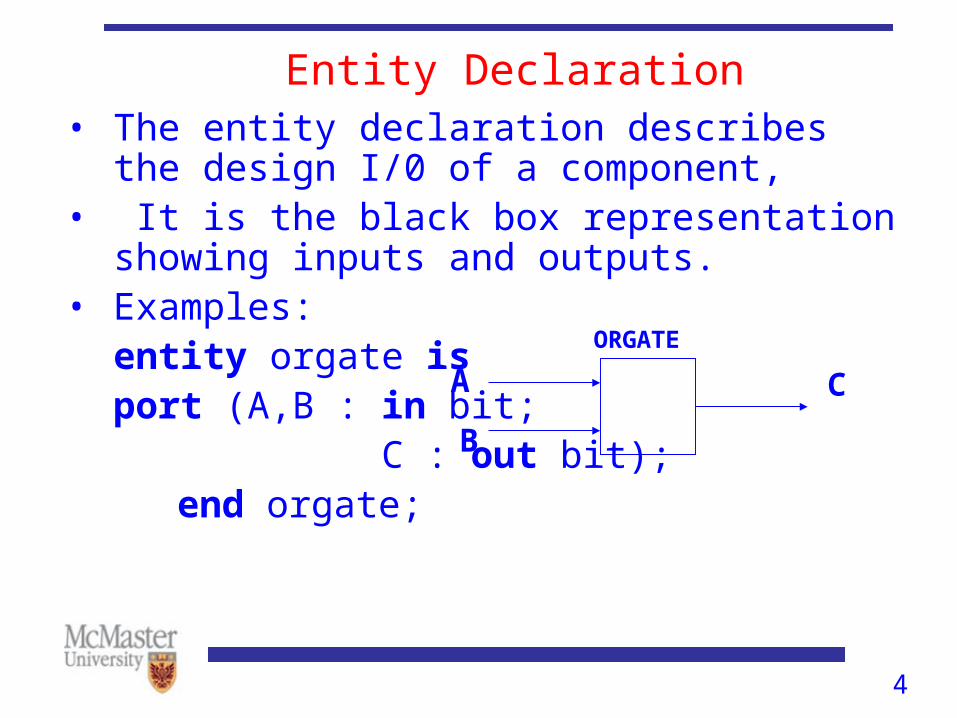
Entity Declaration• The entity declaration describes the design I/0 of a
component,• It is the black box representation showing inputs
and outputs.• Examples:
entity orgate is port (A,B : in bit; C : out bit);
end orgate;
A
B
C
ORGATE
5
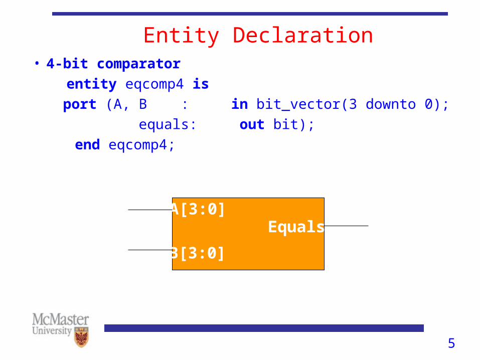
Entity Declaration• 4-bit comparator
entity eqcomp4 is
port (A, B : in bit_vector(3 downto 0);
equals: out bit);
end eqcomp4;eqcomp4
[3:0]A[3:0]
B[3:0]
Equals
eqcomp4Eqcomp4
6
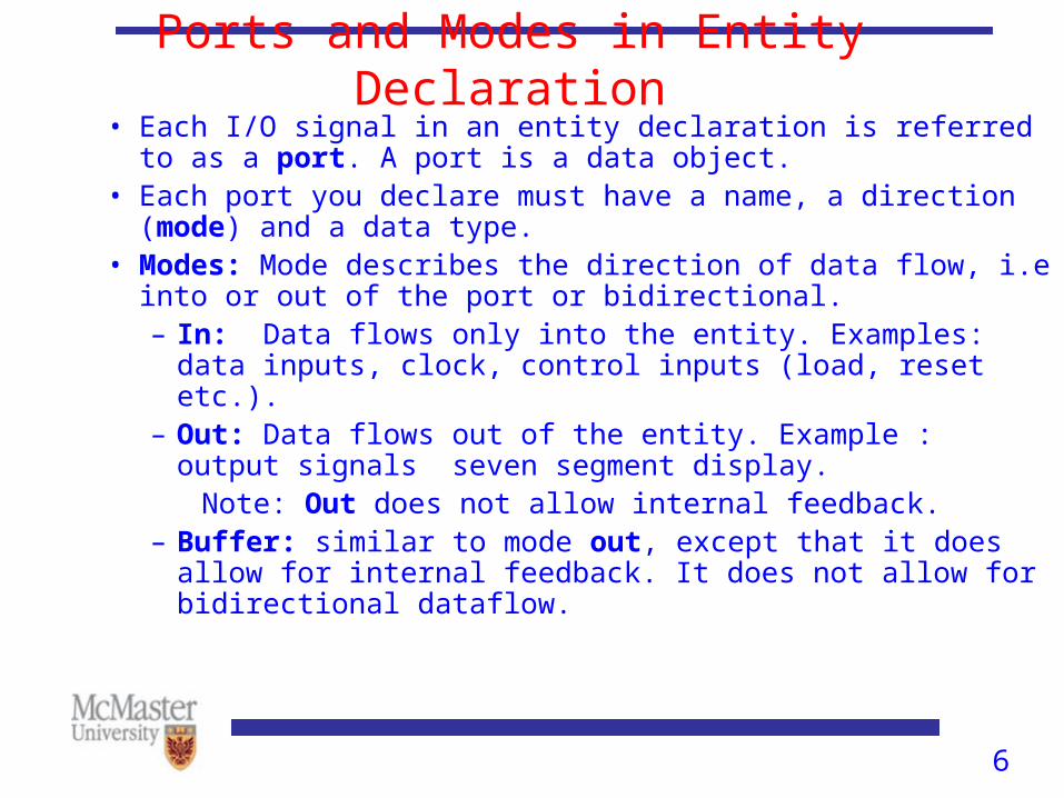
Ports and Modes in Entity Declaration• Each I/O signal in an entity declaration is referred to as a port. A
port is a data object.• Each port you declare must have a name, a direction (mode) and a
data type.• Modes: Mode describes the direction of data flow, i.e into or out of
the port or bidirectional. – In: Data flows only into the entity. Examples: data inputs,
clock, control inputs (load, reset etc.).– Out: Data flows out of the entity. Example : output signals
seven segment display. Note: Out does not allow internal feedback.– Buffer: similar to mode out, except that it does allow for
internal feedback. It does not allow for bidirectional dataflow.
7
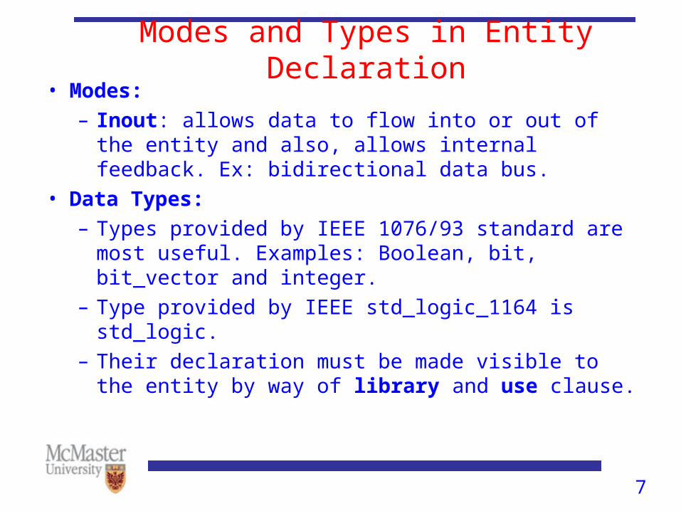
Modes and Types in Entity Declaration• Modes:
– Inout: allows data to flow into or out of the entity and also, allows internal feedback. Ex: bidirectional data bus.
• Data Types:
– Types provided by IEEE 1076/93 standard are most useful. Examples: Boolean, bit, bit_vector and integer.
– Type provided by IEEE std_logic_1164 is std_logic.
– Their declaration must be made visible to the entity by way of library and use clause.
8
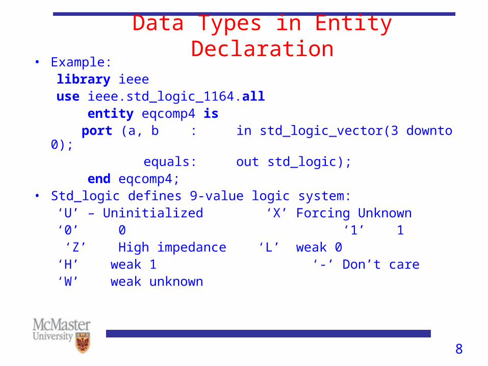
Data Types in Entity Declaration• Example:
library ieeeuse ieee.std_logic_1164.all
entity eqcomp4 is port (a, b : in std_logic_vector(3 downto 0); equals: out std_logic);
end eqcomp4;• Std_logic defines 9-value logic system:
‘U’ – Uninitialized ‘X’ Forcing Unknown‘0’ 0 ‘1’ 1 ‘Z’ High impedance ‘L’ weak 0‘H’ weak 1 ‘-’ Don’t care‘W’ weak unknown
9
Architecture Bodies• Entity declaration is the black box with I/O
description while architecture body provides the functional description of that black box.
• Every architecture body is associated with an entity declaration.
• VHDL architectures are categorized in style as:1.Behavior 2.Dataflow3.Structural
• A design can use any or all of these styles.
10
Behavioral Descriptions• Behavioral descriptions are sometimes referred to as
high-level descriptions because of their resemblance to high level languages such as C and Fortran.
• Advantages: one doesn’t need to focus on the gate-level implementation of a design. Instead focus on accurately modeling its function.
11
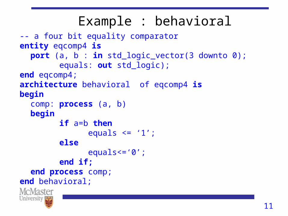
Example : behavioral-- a four bit equality comparator entity eqcomp4 is
port (a, b : in std_logic_vector(3 downto 0);equals: out std_logic);
end eqcomp4;architecture behavioral of eqcomp4 isbegin
comp: process (a, b)begin
if a=b thenequals <= ‘1’;
elseequals<=‘0’;
end if;end process comp;
end behavioral;
12
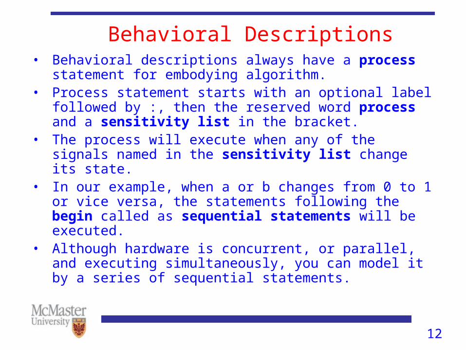
Behavioral Descriptions• Behavioral descriptions always have a process statement for
embodying algorithm.• Process statement starts with an optional label followed by :,
then the reserved word process and a sensitivity list in the bracket.
• The process will execute when any of the signals named in the sensitivity list change its state.
• In our example, when a or b changes from 0 to 1 or vice versa, the statements following the begin called as sequential statements will be executed.
• Although hardware is concurrent, or parallel, and executing simultaneously, you can model it by a series of sequential statements.
13
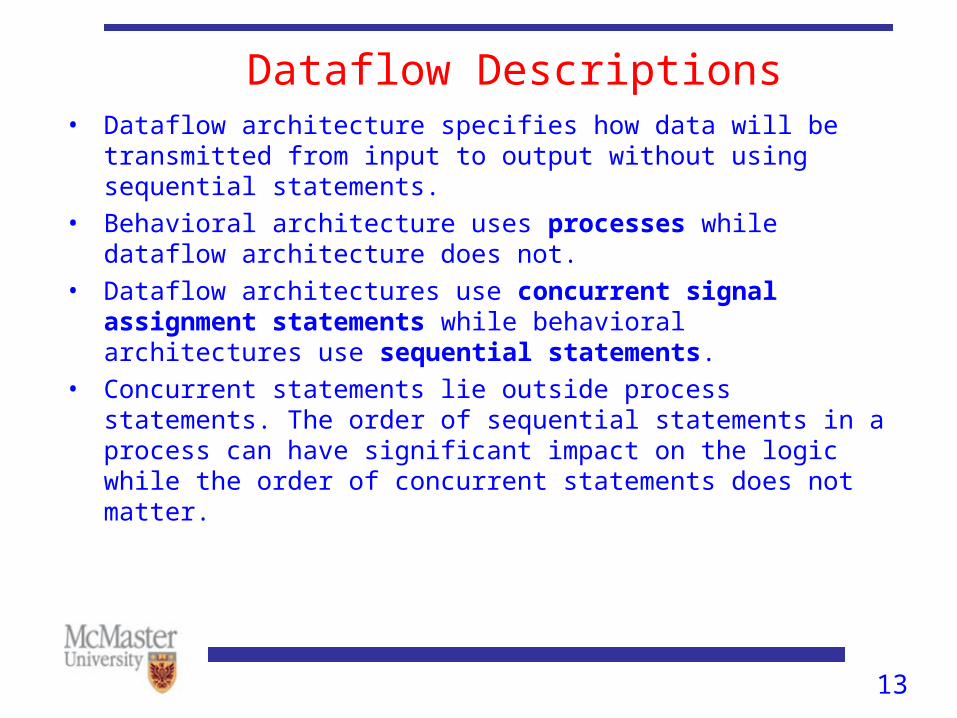
Dataflow Descriptions• Dataflow architecture specifies how data will be transmitted
from input to output without using sequential statements.• Behavioral architecture uses processes while dataflow
architecture does not.• Dataflow architectures use concurrent signal assignment
statements while behavioral architectures use sequential statements.
• Concurrent statements lie outside process statements. The order of sequential statements in a process can have significant impact on the logic while the order of concurrent statements does not matter.
14
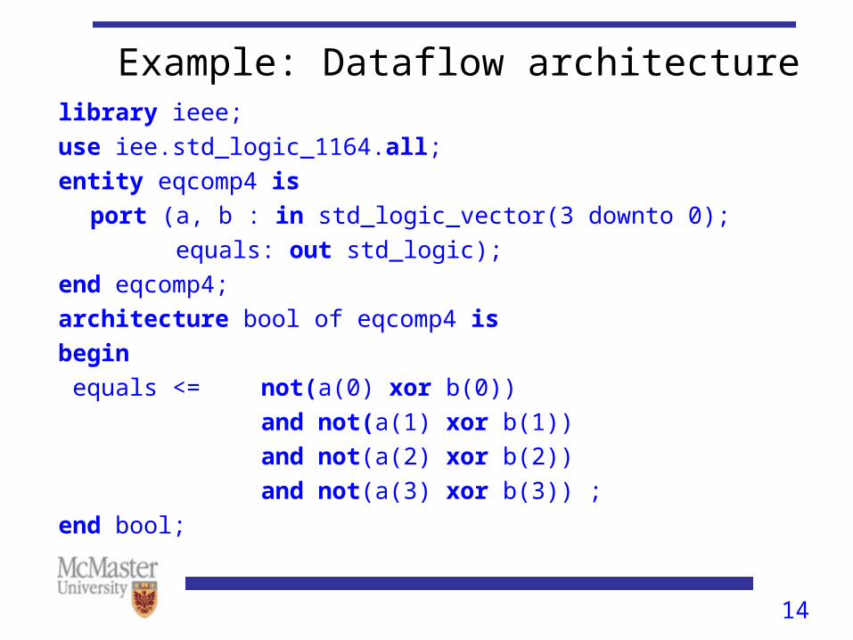
Example: Dataflow architecturelibrary ieee;
use iee.std_logic_1164.all;
entity eqcomp4 is
port (a, b : in std_logic_vector(3 downto 0);
equals: out std_logic);
end eqcomp4;
architecture bool of eqcomp4 is
begin
equals <= not(a(0) xor b(0))
and not(a(1) xor b(1))
and not(a(2) xor b(2))
and not(a(3) xor b(3)) ;
end bool;
15
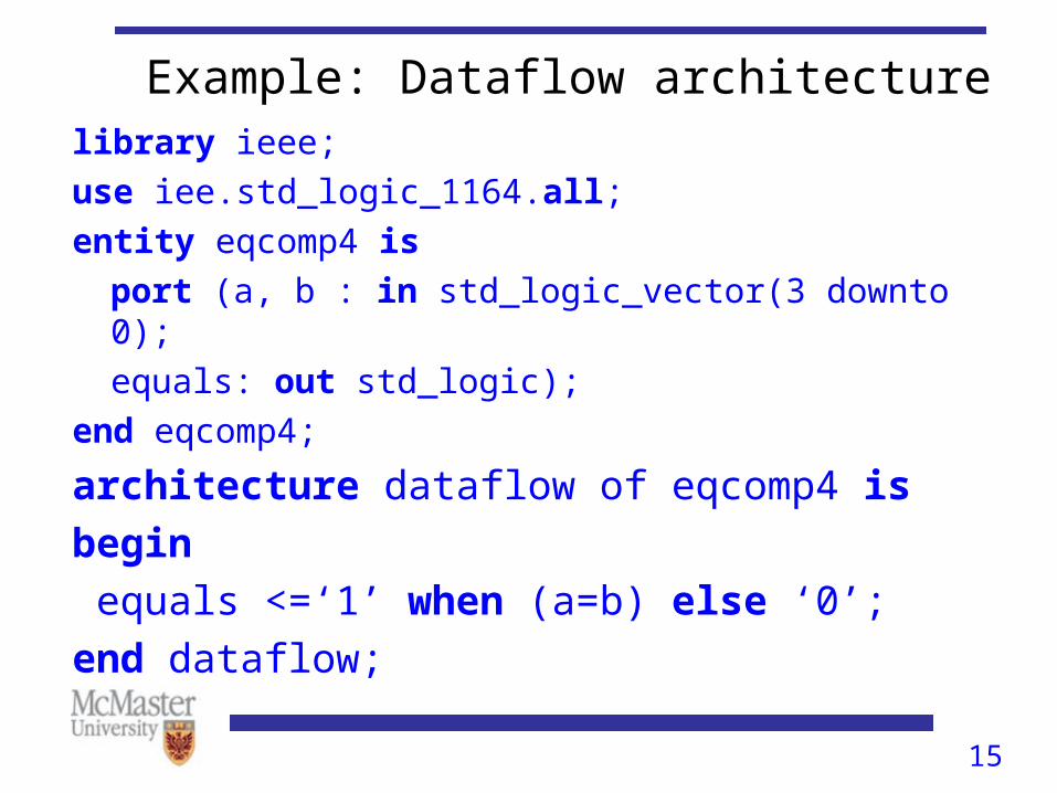
Example: Dataflow architecturelibrary ieee;
use iee.std_logic_1164.all;
entity eqcomp4 is
port (a, b : in std_logic_vector(3 downto 0);
equals: out std_logic);
end eqcomp4;
architecture dataflow of eqcomp4 is
begin
equals <=‘1’ when (a=b) else ‘0’;
end dataflow;
16
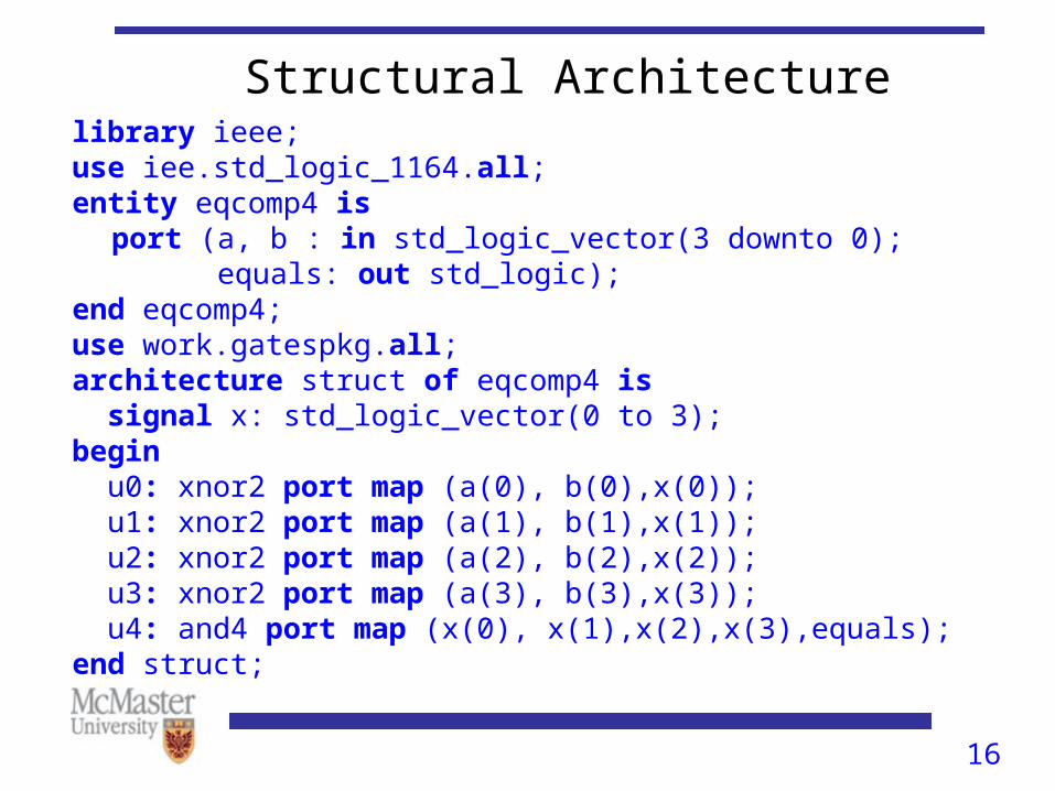
Structural Architecturelibrary ieee;use iee.std_logic_1164.all;entity eqcomp4 is
port (a, b : in std_logic_vector(3 downto 0);equals: out std_logic);
end eqcomp4;use work.gatespkg.all;architecture struct of eqcomp4 is signal x: std_logic_vector(0 to 3);begin u0: xnor2 port map (a(0), b(0),x(0)); u1: xnor2 port map (a(1), b(1),x(1)); u2: xnor2 port map (a(2), b(2),x(2)); u3: xnor2 port map (a(3), b(3),x(3)); u4: and4 port map (x(0), x(1),x(2),x(3),equals);end struct;
17
Structural Architecture• Structural descriptions consist of VHDL netlists –
components are instantiated and connected together with signals.
• Act of instantiation is either
(i) an act of placing a component or
(ii) an instance of a component – that is, a particular occurrence of a component.
18
Identifiers• Basic identifiers are made up of alphabetic, numeric and/or
underscore characters.
– The first character must be a letter.
– The last character can not be an underscore.
– Two underscores in succession are not allowed.
– VHDL reserved words such as entity, is, architecture should not be used as identifiers.
• Upper and lower case letters are equivalent when used in identifiers. The following are equivalent:– Clk, clk, CLK, clK
19
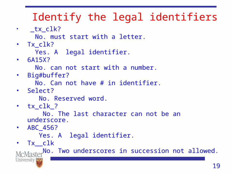
Identify the legal identifiers• _tx_clk? No. must start with a letter.• Tx_clk? Yes. A legal identifier.• 6A15X? No. can not start with a number.• Big#buffer? No. Can not have # in identifier.• Select? No. Reserved word.• tx_clk_? No. The last character can not be an underscore.• ABC_456? Yes. A legal identifier.• Tx__clk No. Two underscores in succession not allowed.
20
Data Objects• Data objects hold value of specified types. They belong to
one of four classes: constants, variables, signals and files.
• Constants: A constant holds a value that can not be changed within the design description.
– Example: constant width: integer := 8;
– Constants are used to improve the readability of code and also makes it easier to modify.
21
Data Objects
• Signals: Signals represent wires and can therefore interconnect components.
– Examples: Ports, inputs or outputs of logic gates.
– Example: signal count: logic_vector(3 downto 0);
– Signals declared as ports have modes. But locally declared signals do not.
• Variables: Variables are used only in processes and must be declared in the declarative region of the architecture. – Example: variable result: std_logic :=‘0’;
– Unlike constants, value of a variable can be changed within the design description.
– Unlike signals, variables do not represent wires or memory elements.
22
Data Objects• Variables:
– Variables are used mainly for computational purposes.
– Variable assignment is immediate, not scheduled.
23
Combinational Logic• Combinational logic can be implemented with concurrent
and sequential statements.
• Concurrent statements are used in dataflow and structural descriptions.
• Sequential statements are used in behavioral descriptions.

24
Four-to-one Multiplexer Using Concurrent Statements
• Selective signal assignment (with-select-when)
a[3:0]
b[3:0]
c[3:0]
d[3:0]
s(0)
S(1)
x[3:0]
00
01
11
10
MUX
25
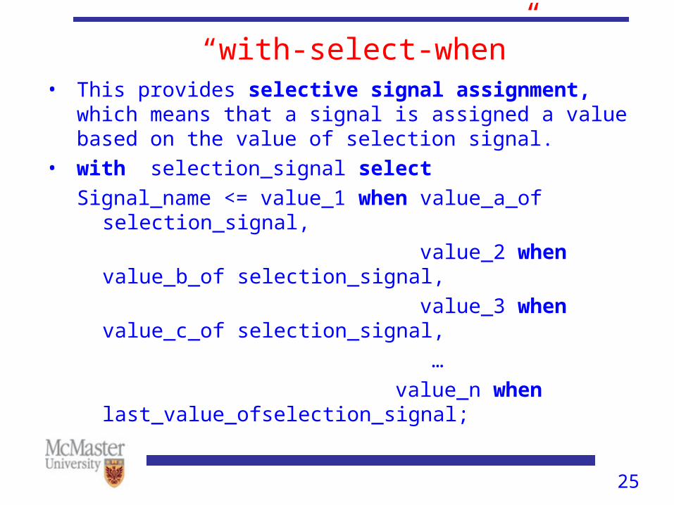
“with-select-when”• This provides selective signal assignment, which means that
a signal is assigned a value based on the value of selection signal.
• with selection_signal select
Signal_name <= value_1 when value_a_of selection_signal,
value_2 when value_b_of selection_signal,
value_3 when value_c_of selection_signal,
…
value_n when last_value_ofselection_signal;

26
“with select when” implementation of MUXentity mux is port(
a,b,c,d : in std_logic_vector(3 downto 0);
s : in std_logic_vector(1 downto 0);
x: out std_logic_vector(3 downto 0));
end mux;
architecture with_select_when of mux is
begin
with s select
x <= a when “00”,
b when “01”,
c when “10”,
d when others;
end with_select_when;
27
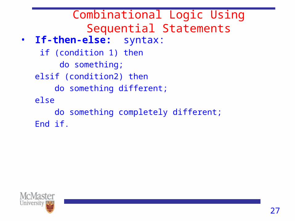
Combinational Logic Using Sequential Statements
• If-then-else: syntax: if (condition 1) then
do something;
elsif (condition2) then
do something different;
else
do something completely different;
End if.
28
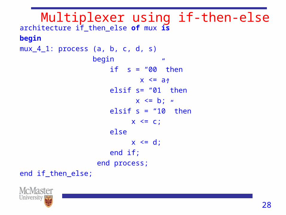
Multiplexer using if-then-elsearchitecture if_then_else of mux is
begin
mux_4_1: process (a, b, c, d, s)
begin
if s = “00” then
x <= a;
elsif s= “01” then
x <= b;
elsif s = “10” then
x <= c;
else
x <= d;
end if;
end process;
end if_then_else;

29
Synchronous logic• VHDL implementation of D-type flip-flop (DFF):
entity dff_logic is port (
d, clk : in std_logic;
q : out std_logic);
end dff_logic;
architecture a of dff_logic is
begin
process (clk) begin
if (clk’event and clk = ‘1’) then
q <= d;
end if;
end process;
end a;
30
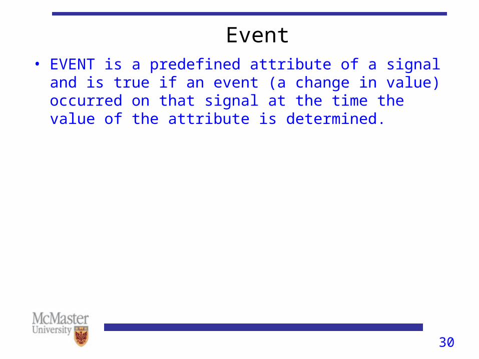
Event• EVENT is a predefined attribute of a signal and is true if an
event (a change in value) occurred on that signal at the time the value of the attribute is determined.

31
Wait• When a process has a sensitivity list it is always suspended
after executing the last statement in the process
• Wait is an alternative way of suspending a process
• Syntax:wait on sensitivity_list
wait until boolean_expression;
wait for time_expression;
• Examples: wait on a,b;
wait until ( x < 10);
wait for 10 ns;
32
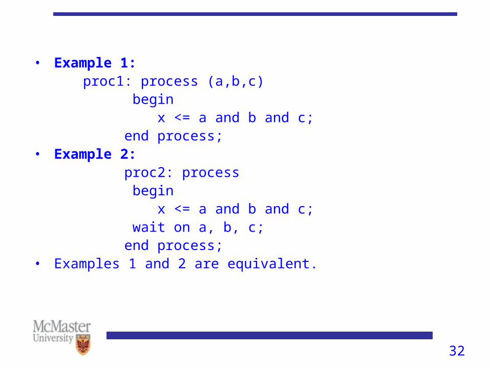
• Example 1: proc1: process (a,b,c) begin x <= a and b and c; end process;• Example 2: proc2: process begin x <= a and b and c; wait on a, b, c; end process;• Examples 1 and 2 are equivalent.
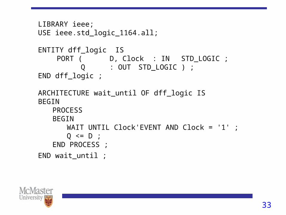
33Figure 7.39 Code for a D flip-flop using WAIT UNTIL
LIBRARY ieee; USE ieee.std_logic_1164.all;
ENTITY dff_logic IS PORT ( D, Clock : IN STD_LOGIC ;
Q : OUT STD_LOGIC ) ; END dff_logic ;
ARCHITECTURE wait_until OF dff_logic IS BEGIN
PROCESSBEGIN
WAIT UNTIL Clock'EVENT AND Clock = '1' ;Q <= D ;
END PROCESS ;
END wait_until ;
34
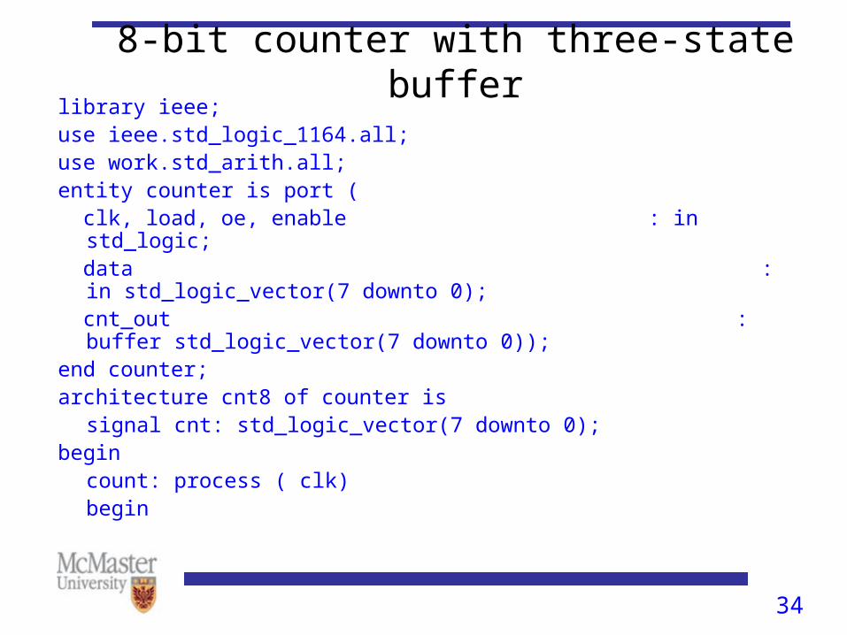
8-bit counter with three-state bufferlibrary ieee;use ieee.std_logic_1164.all;use work.std_arith.all;entity counter is port ( clk, load, oe, enable : in std_logic; data : in std_logic_vector(7 downto 0); cnt_out : buffer std_logic_vector(7 downto 0));end counter;architecture cnt8 of counter is
signal cnt: std_logic_vector(7 downto 0);begin
count: process ( clk)begin
35
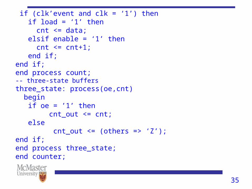
if (clk’event and clk = ‘1’) then if load = ‘1’ then cnt <= data; elsif enable = ‘1’ then cnt <= cnt+1; end if;end if;end process count; -- three-state buffersthree_state: process(oe,cnt) begin if oe = ’1’ then cnt_out <= cnt; else cnt_out <= (others => ‘Z’);end if;end process three_state;end counter;
36
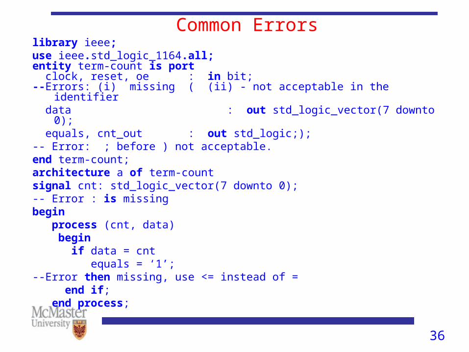
Common Errorslibrary ieee;use ieee.std_logic_1164.all;entity term-count is port clock, reset, oe : in bit;--Errors: (i) missing ( (ii) - not acceptable in the identifier data : out std_logic_vector(7 downto 0); equals, cnt_out : out std_logic;); -- Error: ; before ) not acceptable.end term-count;architecture a of term-count signal cnt: std_logic_vector(7 downto 0);-- Error : is missingbegin process (cnt, data) begin if data = cnt equals = ‘1’;--Error then missing, use <= instead of = end if; end process;
37
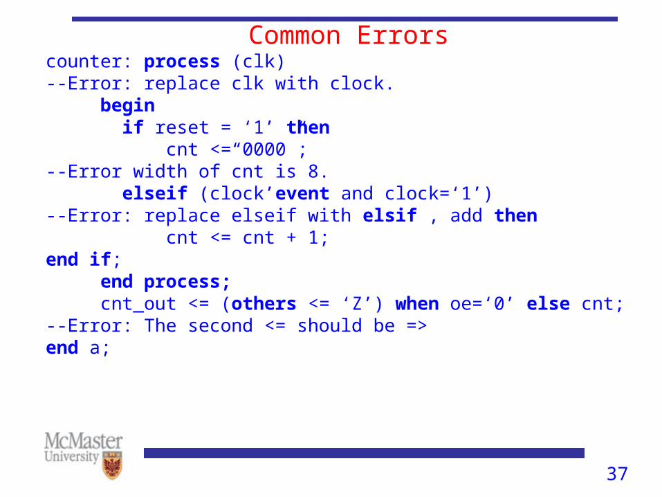
Common Errorscounter: process (clk)--Error: replace clk with clock. begin if reset = ‘1’ then cnt <=“0000”;--Error width of cnt is 8. elseif (clock’event and clock=‘1’)--Error: replace elseif with elsif , add then cnt <= cnt + 1;end if; end process; cnt_out <= (others <= ‘Z’) when oe=‘0’ else cnt;--Error: The second <= should be =>end a;
38
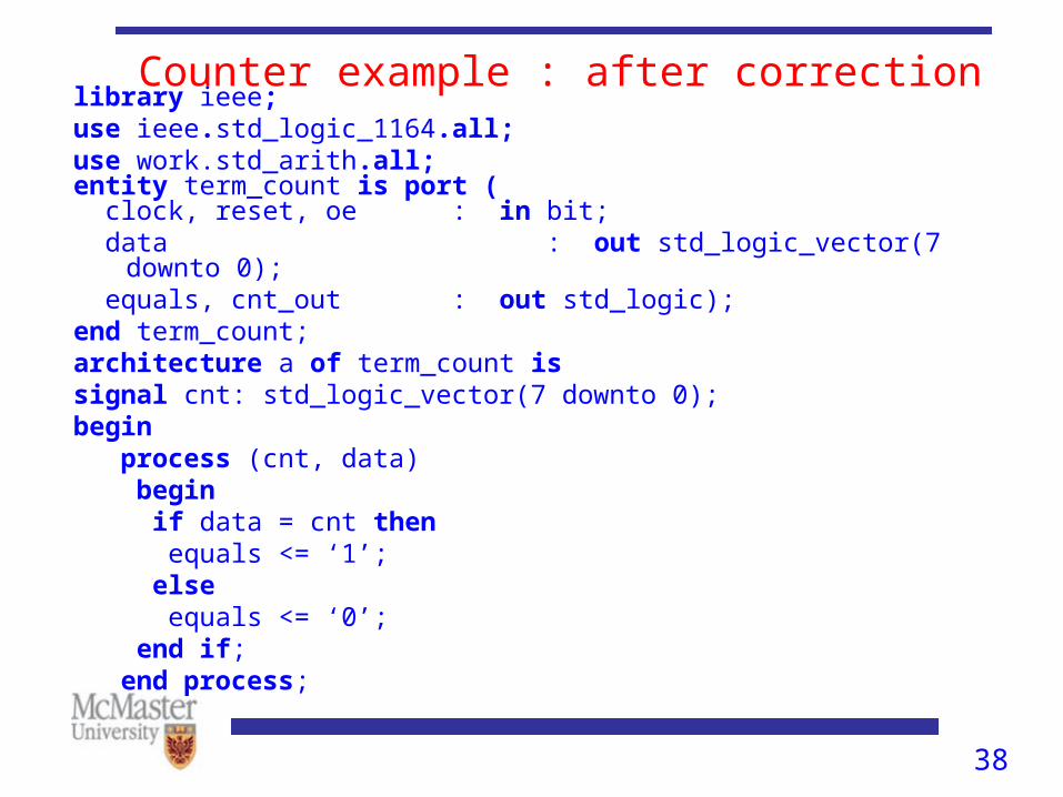
Counter example : after correctionlibrary ieee;use ieee.std_logic_1164.all;use work.std_arith.all;entity term_count is port ( clock, reset, oe : in bit; data : out std_logic_vector(7 downto 0); equals, cnt_out : out std_logic); end term_count;architecture a of term_count issignal cnt: std_logic_vector(7 downto 0);begin process (cnt, data) begin if data = cnt then equals <= ‘1’; else equals <= ‘0’; end if; end process;
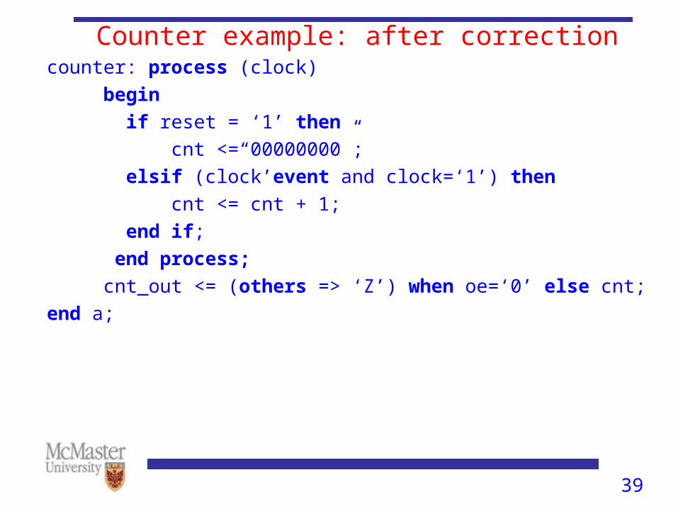
39
Counter example: after correctioncounter: process (clock)
begin
if reset = ‘1’ then
cnt <=“00000000”;
elsif (clock’event and clock=‘1’) then
cnt <= cnt + 1;
end if;
end process;
cnt_out <= (others => ‘Z’) when oe=‘0’ else cnt;
end a;

40
Counter example: after correctioncounter: process (clock)
begin
if reset = ‘1’ then
cnt <=“00000000”;
elsif (clock’event and clock=‘1’) then
cnt <= cnt + 1;
end if;
end process;
cnt_out <= (others => ‘Z’) when oe=‘0’ else cnt;
end a;

41
Functions, Packages, Components and Procedures
function bool2bit(a:BOOLEAN) return bit is begin if a then return ‘1’; else return ‘0’; end if;end bool2bit;
42
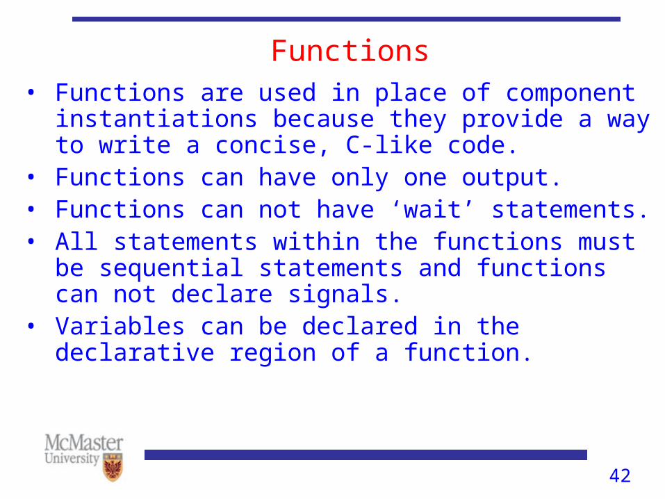
Functions• Functions are used in place of component instantiations
because they provide a way to write a concise, C-like code.
• Functions can have only one output.• Functions can not have ‘wait’ statements.• All statements within the functions must be sequential
statements and functions can not declare signals.• Variables can be declared in the declarative region of a
function.
43
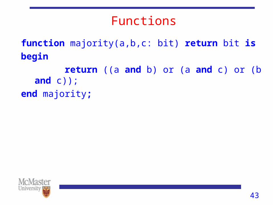
Functions
function majority(a,b,c: bit) return bit is
begin
return ((a and b) or (a and c) or (b and c));
end majority;
44
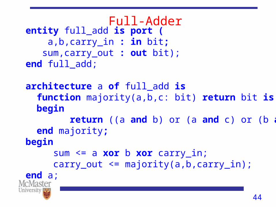
Full-Adderentity full_add is port ( a,b,carry_in : in bit; sum,carry_out : out bit);end full_add;
architecture a of full_add is function majority(a,b,c: bit) return bit is begin return ((a and b) or (a and c) or (b and c)); end majority;begin sum <= a xor b xor carry_in; carry_out <= majority(a,b,carry_in);end a;
45
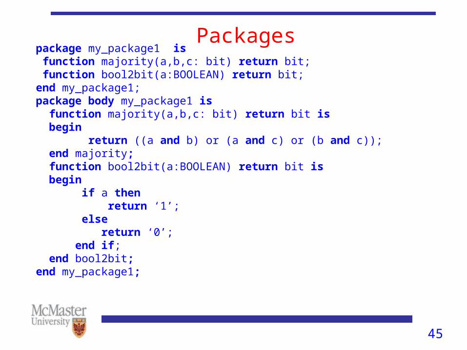
Packages package my_package1 is function majority(a,b,c: bit) return bit; function bool2bit(a:BOOLEAN) return bit;end my_package1;package body my_package1 is function majority(a,b,c: bit) return bit is begin return ((a and b) or (a and c) or (b and c)); end majority; function bool2bit(a:BOOLEAN) return bit is begin if a then return ‘1’; else return ‘0’; end if; end bool2bit;end my_package1;
46
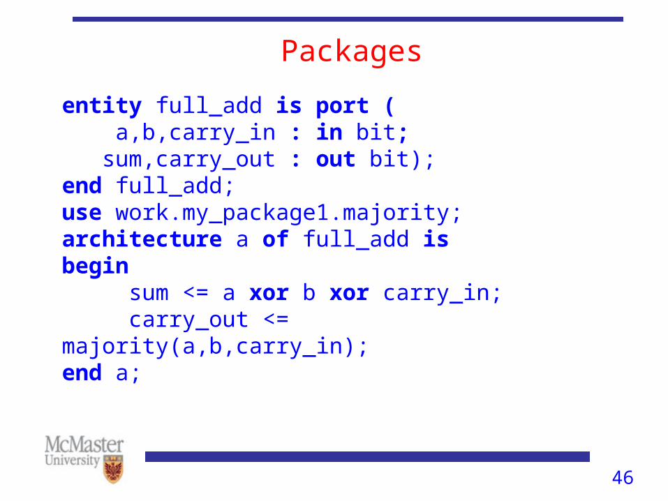
Packages
entity full_add is port ( a,b,carry_in : in bit; sum,carry_out : out bit);end full_add;use work.my_package1.majority;architecture a of full_add isbegin sum <= a xor b xor carry_in; carry_out <= majority(a,b,carry_in);end a;
47
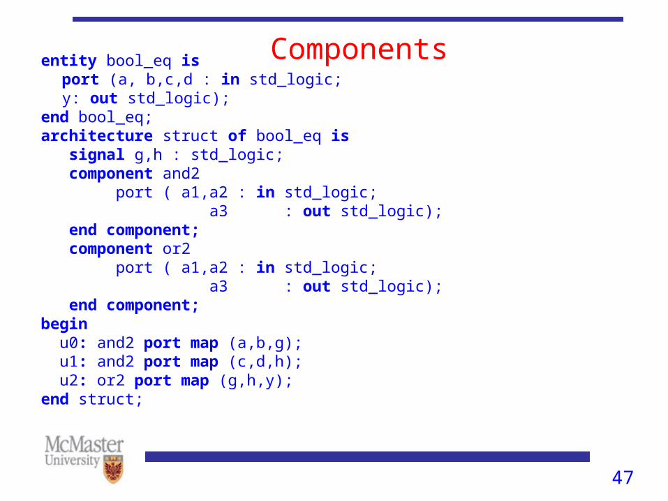
Componentsentity bool_eq isport (a, b,c,d : in std_logic;
y: out std_logic);end bool_eq;architecture struct of bool_eq is signal g,h : std_logic; component and2 port ( a1,a2 : in std_logic; a3 : out std_logic); end component; component or2 port ( a1,a2 : in std_logic; a3 : out std_logic); end component;begin u0: and2 port map (a,b,g); u1: and2 port map (c,d,h); u2: or2 port map (g,h,y); end struct;
48
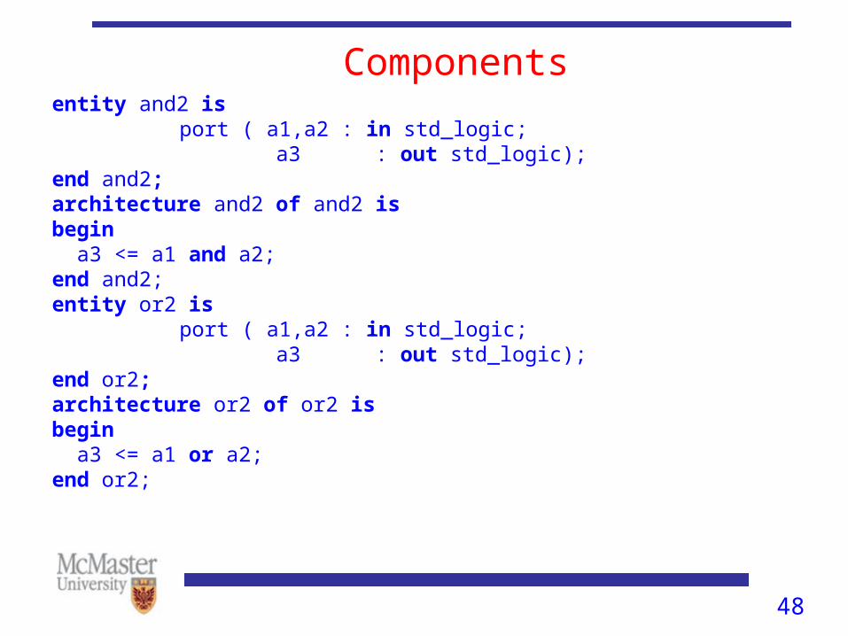
Componentsentity and2 is
port ( a1,a2 : in std_logic; a3 : out std_logic);end and2;architecture and2 of and2 isbegin a3 <= a1 and a2;end and2;entity or2 is
port ( a1,a2 : in std_logic; a3 : out std_logic);end or2;architecture or2 of or2 isbegin a3 <= a1 or a2;end or2;
49
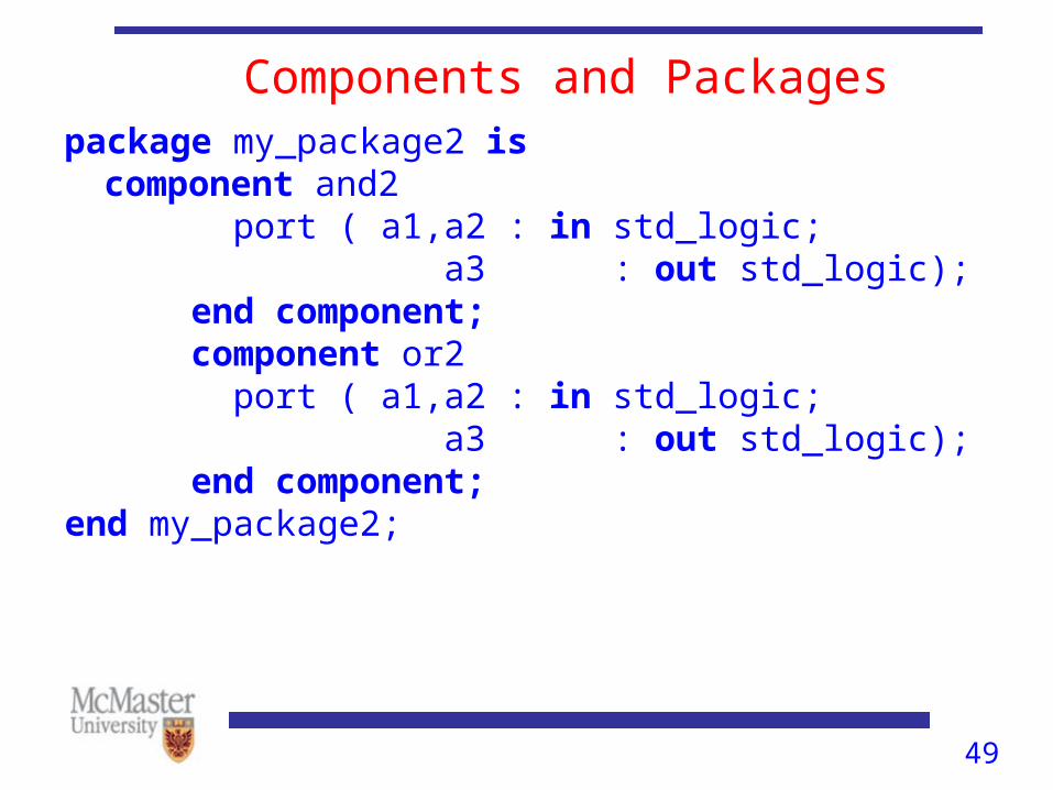
Components and Packagespackage my_package2 is
component and2 port ( a1,a2 : in std_logic; a3 : out std_logic); end component; component or2 port ( a1,a2 : in std_logic; a3 : out std_logic); end component;end my_package2;
50
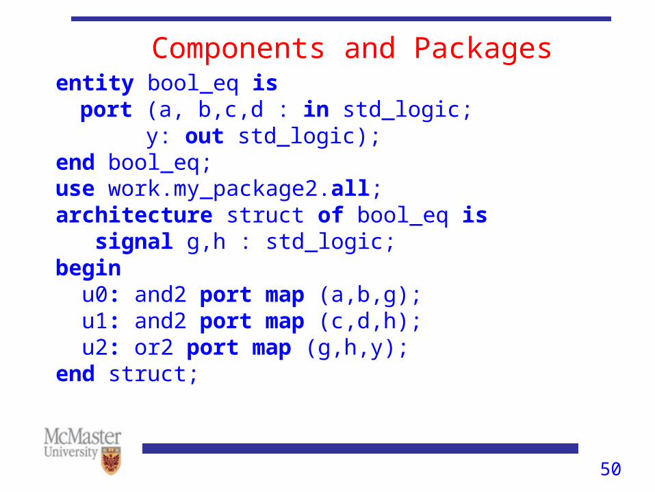
Components and Packagesentity bool_eq is
port (a, b,c,d : in std_logic;y: out std_logic);
end bool_eq;use work.my_package2.all;architecture struct of bool_eq is signal g,h : std_logic;begin u0: and2 port map (a,b,g); u1: and2 port map (c,d,h); u2: or2 port map (g,h,y); end struct;
51
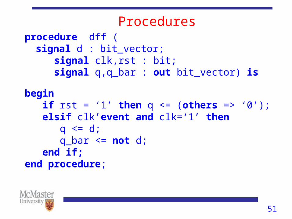
Proceduresprocedure dff (
signal d : bit_vector; signal clk,rst : bit; signal q,q_bar : out bit_vector) isbegin if rst = ‘1’ then q <= (others => ‘0’); elsif clk’event and clk=‘1’ then q <= d; q_bar <= not d; end if;end procedure;
52
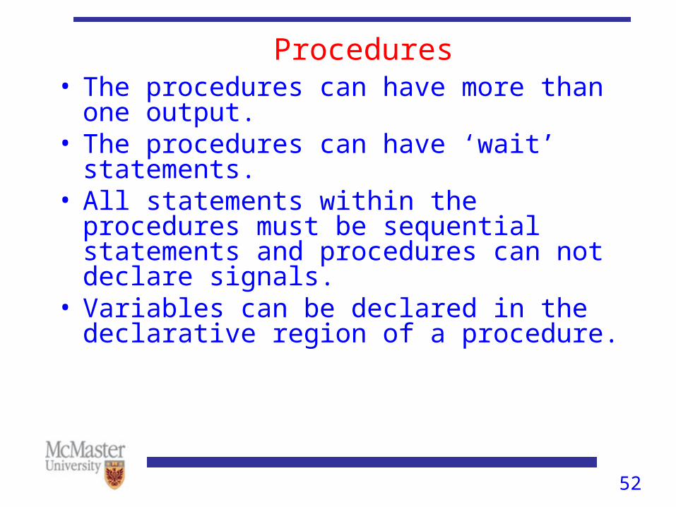
Procedures• The procedures can have more than one output. • The procedures can have ‘wait’ statements.• All statements within the procedures must be
sequential statements and procedures can not declare signals.
• Variables can be declared in the declarative region of a procedure.
53
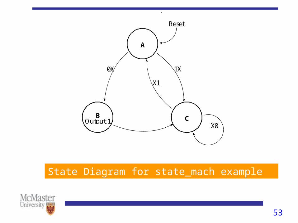
A
R e s e t
C B O u t p u t 1
X 1
1 X 0 X
X 0
State Diagram for state_mach example
54
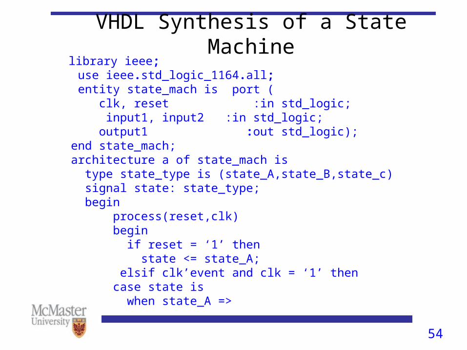
VHDL Synthesis of a State Machine library ieee; use ieee.std_logic_1164.all; entity state_mach is port ( clk, reset :in std_logic; input1, input2 :in std_logic; output1 :out std_logic); end state_mach; architecture a of state_mach is type state_type is (state_A,state_B,state_c) signal state: state_type; begin process(reset,clk) begin if reset = ‘1’ then state <= state_A; elsif clk’event and clk = ‘1’ then case state is when state_A =>
55
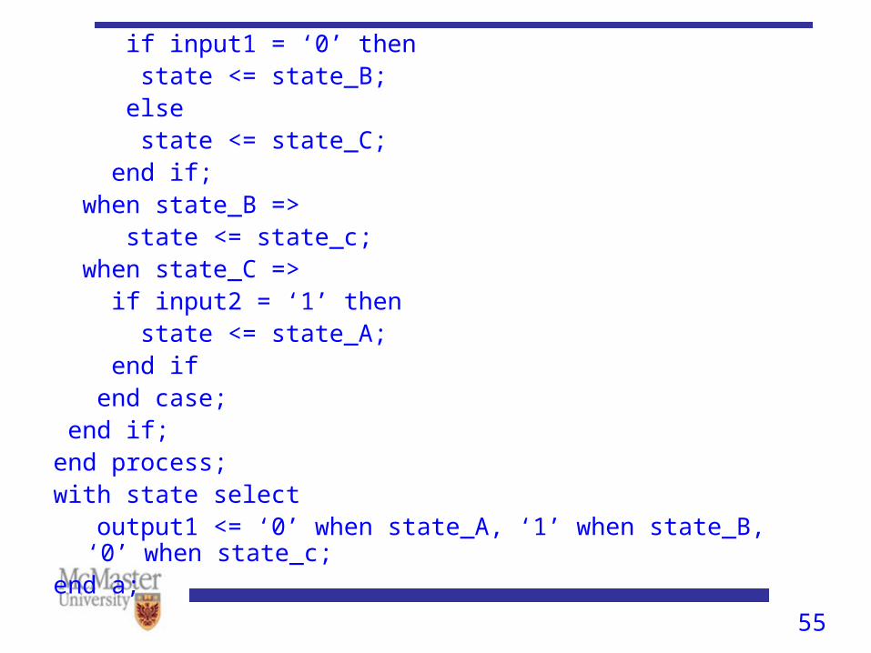
if input1 = ‘0’ then state <= state_B; else state <= state_C; end if; when state_B => state <= state_c; when state_C => if input2 = ‘1’ then state <= state_A; end if end case; end if;end process;with state select output1 <= ‘0’ when state_A, ‘1’ when state_B, ‘0’ when state_c; end a;
56
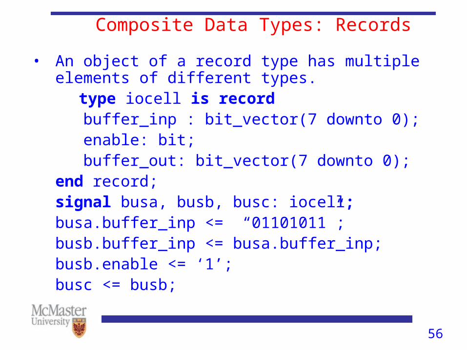
Composite Data Types: Records
• An object of a record type has multiple elements of different types.
type iocell is record buffer_inp : bit_vector(7 downto 0); enable: bit; buffer_out: bit_vector(7 downto 0);end record;signal busa, busb, busc: iocell;busa.buffer_inp <= “01101011”;busb.buffer_inp <= busa.buffer_inp;busb.enable <= ‘1’;busc <= busb;
57
Comparison of Logic Technologies• Traditional IC chips such as MSI TTL perform a fixed
operation defined by the device manufactures. The user must connect the chips to build a circuit.
• Application Specific Integrated Circuits (ASIC), Complex Programmable Logic Devices (CPLD) and Field Programmable Gate Array (FPGA) are ICs whose internal function is defined by the user.
• For CPLD or FPGA, user programming is required to perform the desired operation while ASIC requires a customized manufacturing step for the user defined operation.
58
Data Types and Subtypes• Besides predefined types (e.g., BIT, STD_LOGIC) user can
define their own types in VHDL.
• The command for this purpose is type
• Example:type DIGIT is (‘0’,’1’,’2’,’3’,’4’,’5’,’6’,’7’,’8’,’9’);
• A subtype is a type with a constraint
• Example:subtype MIDDLE is DIGIT range ’3’ to ’7’;
59
Data types • An array object can be assigned to another array object of the
same type.
• Assignment can be made to an entire array, or to an element or to a slice.
• Example:SIGNAL X: STD_LOGIC_VECTOR(0 to 3);
X <=“1100”;
X(3) <=‘0’;
X(0 to 2) <=“101”;
60
Array type
• Multiple Elements having the same type
• Examples:
type data_word is array (7 downto 0) of std_logic;
type ROM is array (0 to 125) of data_word;
type decode_matrix is array (positive range 15 downto 1, natural range 3 downto 0) of std_logic;
• Positive and natural are predefined subtypes of integer:
subtype natural is integer range 0 to integer’high;
subtype positive is integer range 1 to integer’high;
61
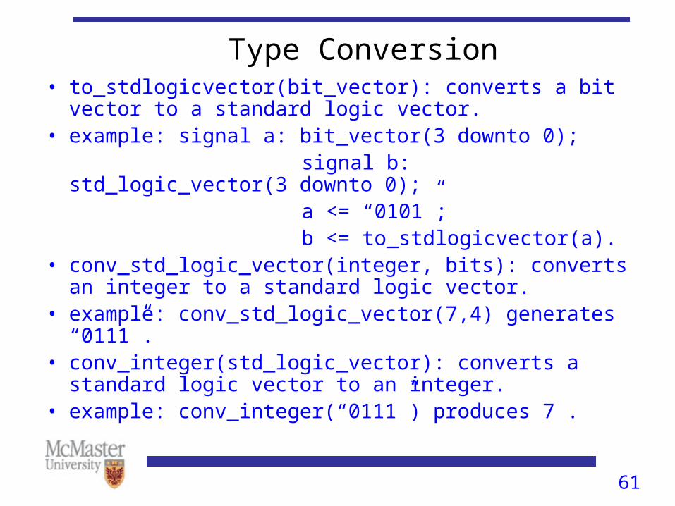
Type Conversion• to_stdlogicvector(bit_vector): converts a bit vector to a
standard logic vector.• example: signal a: bit_vector(3 downto 0); signal b: std_logic_vector(3 downto 0); a <= “0101”; b <= to_stdlogicvector(a).• conv_std_logic_vector(integer, bits): converts an integer to a
standard logic vector.• example: conv_std_logic_vector(7,4) generates “0111”.• conv_integer(std_logic_vector): converts a standard logic
vector to an integer.• example: conv_integer(“0111”) produces 7 .

62
Attributes• Scalar types have attributes. The value attributes are ‘left,
‘right, ‘high, ‘low and ‘length.
• ‘left yields the leftmost value of a type and ‘right the rightmost.
• ‘high yields the greatest value of a type. For enumeration types, ‘high and ‘right yield the same value.
• For integer ranges, ‘high yields the greatest integer in the range.
63
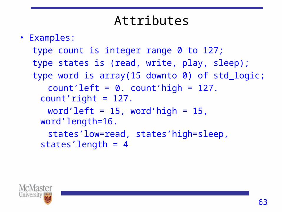
Attributes• Examples:
type count is integer range 0 to 127;
type states is (read, write, play, sleep);
type word is array(15 downto 0) of std_logic;
count’left = 0. count’high = 127. count’right = 127.
word’left = 15, word’high = 15, word’length=16.
states’low=read, states’high=sleep, states’length = 4
64
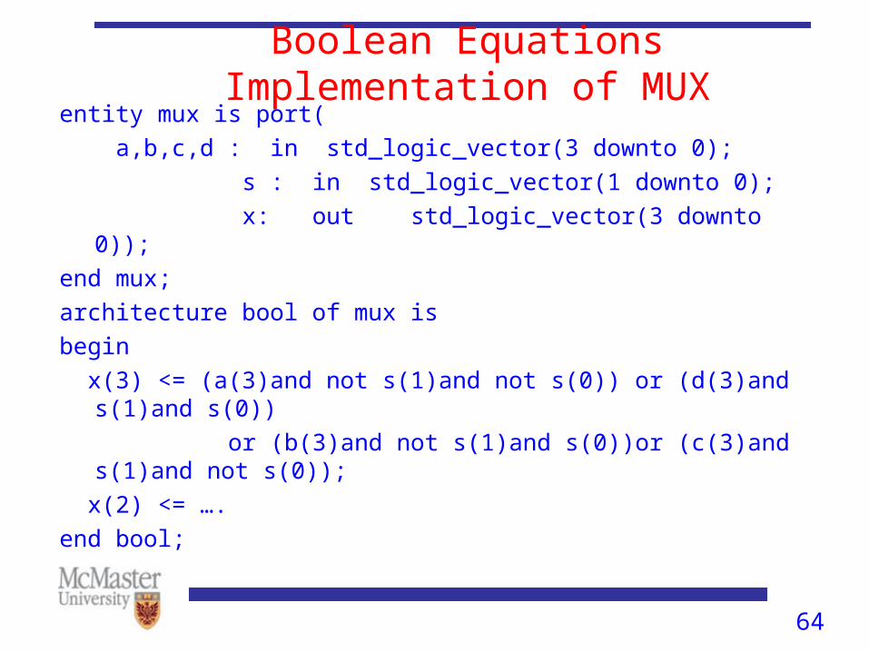
Boolean Equations Implementation of MUXentity mux is port(
a,b,c,d : in std_logic_vector(3 downto 0);
s : in std_logic_vector(1 downto 0);
x: out std_logic_vector(3 downto 0));
end mux;
architecture bool of mux is
begin
x(3) <= (a(3)and not s(1)and not s(0)) or (d(3)and s(1)and s(0))
or (b(3)and not s(1)and s(0))or (c(3)and s(1)and not s(0));
x(2) <= ….
end bool;
65
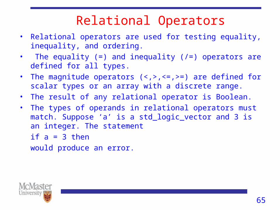
Relational Operators• Relational operators are used for testing equality, inequality, and
ordering.• The equality (=) and inequality (/=) operators are defined for all
types.• The magnitude operators (<,>,<=,>=) are defined for scalar types
or an array with a discrete range. • The result of any relational operator is Boolean.• The types of operands in relational operators must match. Suppose
‘a’ is a std_logic_vector and 3 is an integer. The statement
if a = 3 then
would produce an error.

66
Overloaded Operators• But, relational operators may be overloaded.
• Many overloaded operators are defined in the IEEE 1164 and 1076.3 standards.
• For example, IEEE 1076.3 defines functions to overload = operator for the types signed and integer.
• std_arith package defines new functions and overloads the arithmetic operators to handle the type std_logic_vector and interpreting as unsigned.
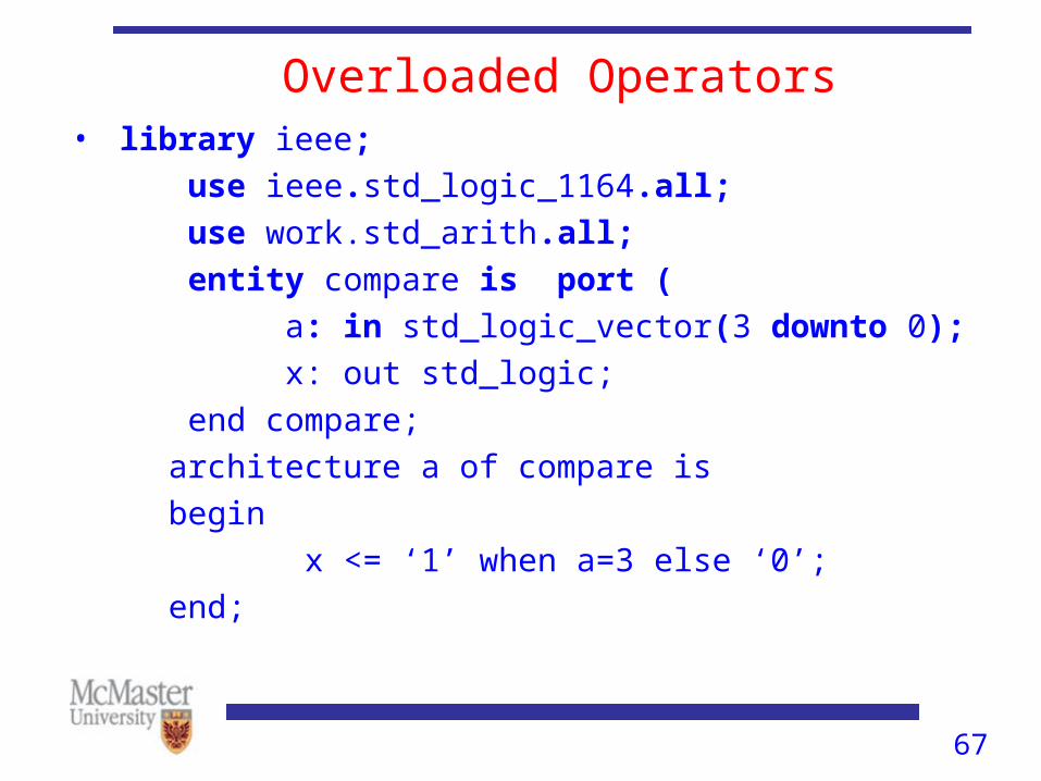
67
Overloaded Operators• library ieee;
use ieee.std_logic_1164.all;
use work.std_arith.all;
entity compare is port (
a: in std_logic_vector(3 downto 0);
x: out std_logic;
end compare;
architecture a of compare is
begin
x <= ‘1’ when a=3 else ‘0’;
end;
68
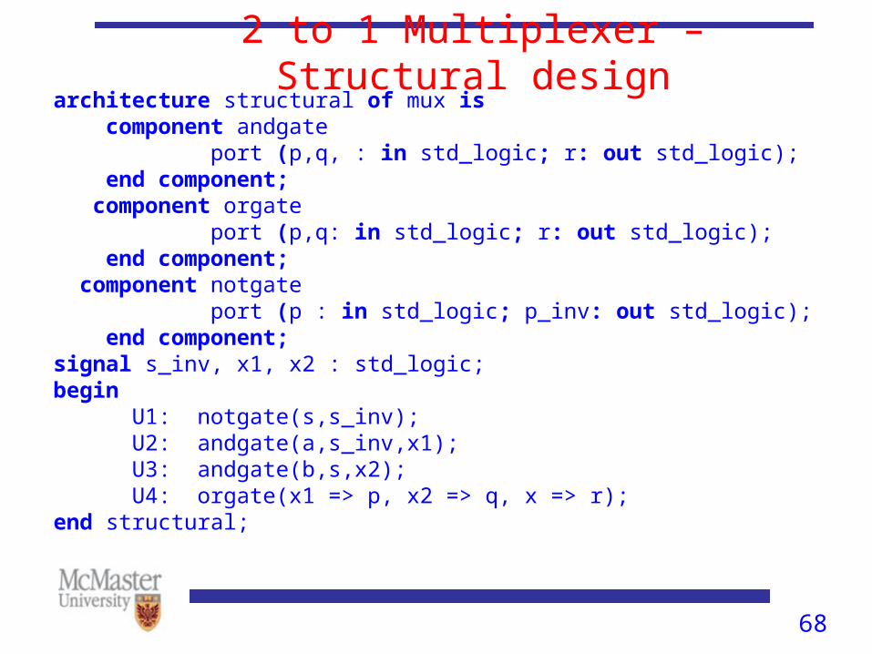
2 to 1 Multiplexer – Structural designarchitecture structural of mux is component andgate port (p,q, : in std_logic; r: out std_logic); end component; component orgate port (p,q: in std_logic; r: out std_logic); end component; component notgate port (p : in std_logic; p_inv: out std_logic); end component;signal s_inv, x1, x2 : std_logic;begin U1: notgate(s,s_inv); U2: andgate(a,s_inv,x1); U3: andgate(b,s,x2); U4: orgate(x1 => p, x2 => q, x => r);end structural;
69
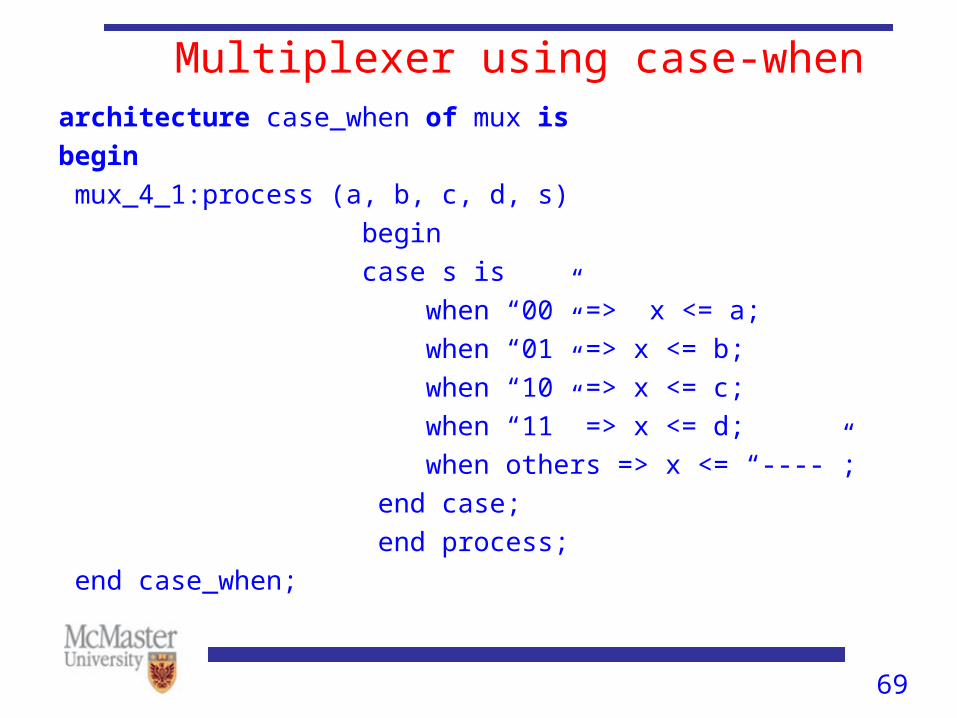
Multiplexer using case-whenarchitecture case_when of mux is
begin
mux_4_1:process (a, b, c, d, s)
begin
case s is
when “00” => x <= a;
when “01” => x <= b;
when “10” => x <= c;
when “11” => x <= d;
when others => x <= “----”;
end case;
end process;
end case_when;
70
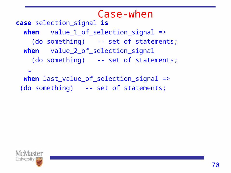
Case-whencase selection_signal is
when value_1_of_selection_signal =>
(do something) -- set of statements;
when value_2_of_selection_signal
(do something) -- set of statements;
…
when last_value_of_selection_signal =>
(do something) -- set of statements;
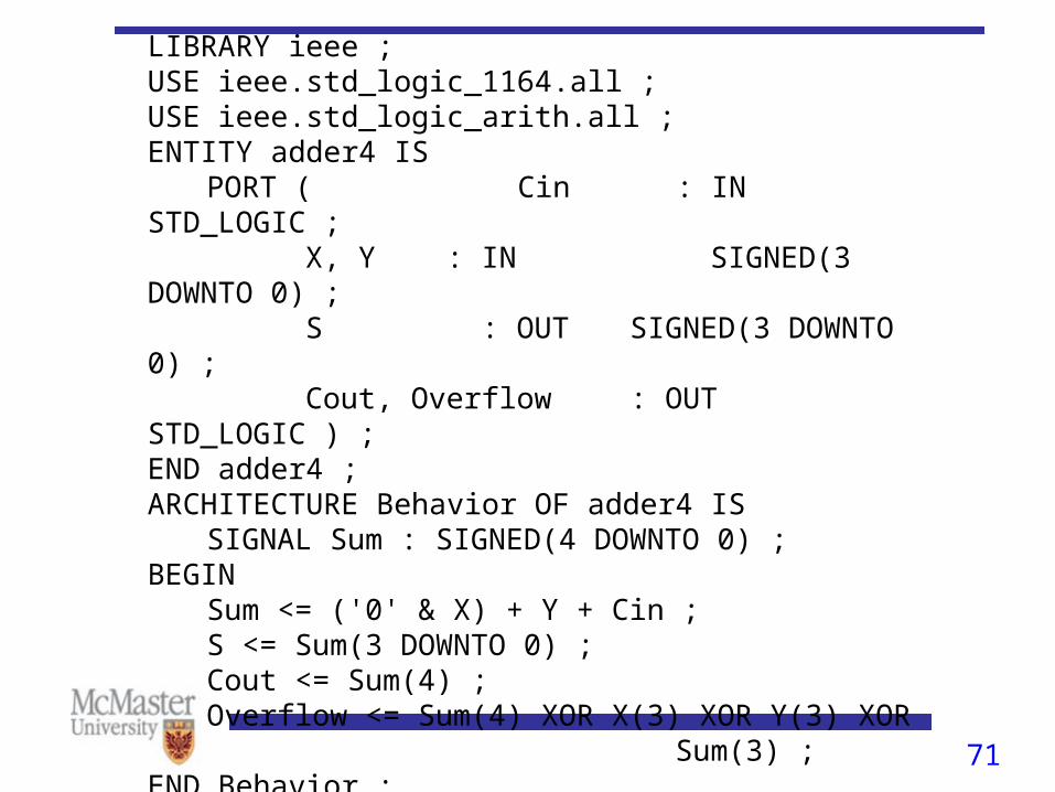
71Figure 5.30 Use of the arithmetic package
LIBRARY ieee ;USE ieee.std_logic_1164.all ;USE ieee.std_logic_arith.all ;ENTITY adder4 IS
PORT ( Cin : IN STD_LOGIC ;X, Y : IN SIGNED(3 DOWNTO 0) ;S : OUT SIGNED(3 DOWNTO 0) ;Cout, Overflow : OUT STD_LOGIC ) ;
END adder4 ;ARCHITECTURE Behavior OF adder4 IS
SIGNAL Sum : SIGNED(4 DOWNTO 0) ;BEGIN
Sum <= ('0' & X) + Y + Cin ;S <= Sum(3 DOWNTO 0) ;Cout <= Sum(4) ;Overflow <= Sum(4) XOR X(3) XOR Y(3) XOR
Sum(3) ;END Behavior ;
4 BIT ADDER
72
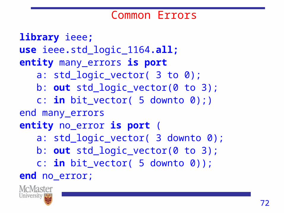
Common Errors
library ieee;use ieee.std_logic_1164.all;entity many_errors is port a: std_logic_vector( 3 to 0); b: out std_logic_vector(0 to 3); c: in bit_vector( 5 downto 0);)end many_errorsentity no_error is port ( a: std_logic_vector( 3 downto 0); b: out std_logic_vector(0 to 3); c: in bit_vector( 5 downto 0));end no_error;
73
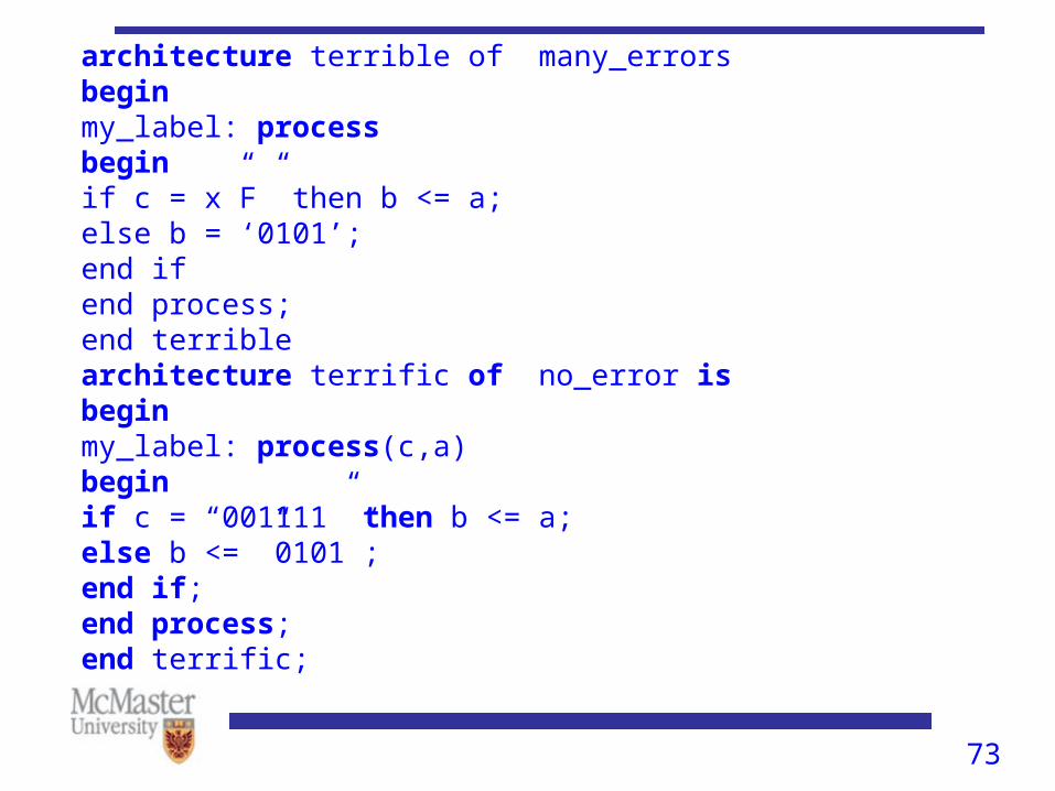
architecture terrible of many_errorsbeginmy_label: processbeginif c = x”F” then b <= a;else b = ‘0101’;end ifend process;end terrible architecture terrific of no_error isbeginmy_label: process(c,a)beginif c = “001111” then b <= a;else b <= ”0101”;end if;end process;end terrific;
74
Resets in Synchronous logic• According to the VHDL standard for simulation, if a
signal is not explicitly initialized, it gets initialized to the ‘left of its type.
• In the hardware world, however, this is not always true. So, you have to explicitly initialize it in the code.
75
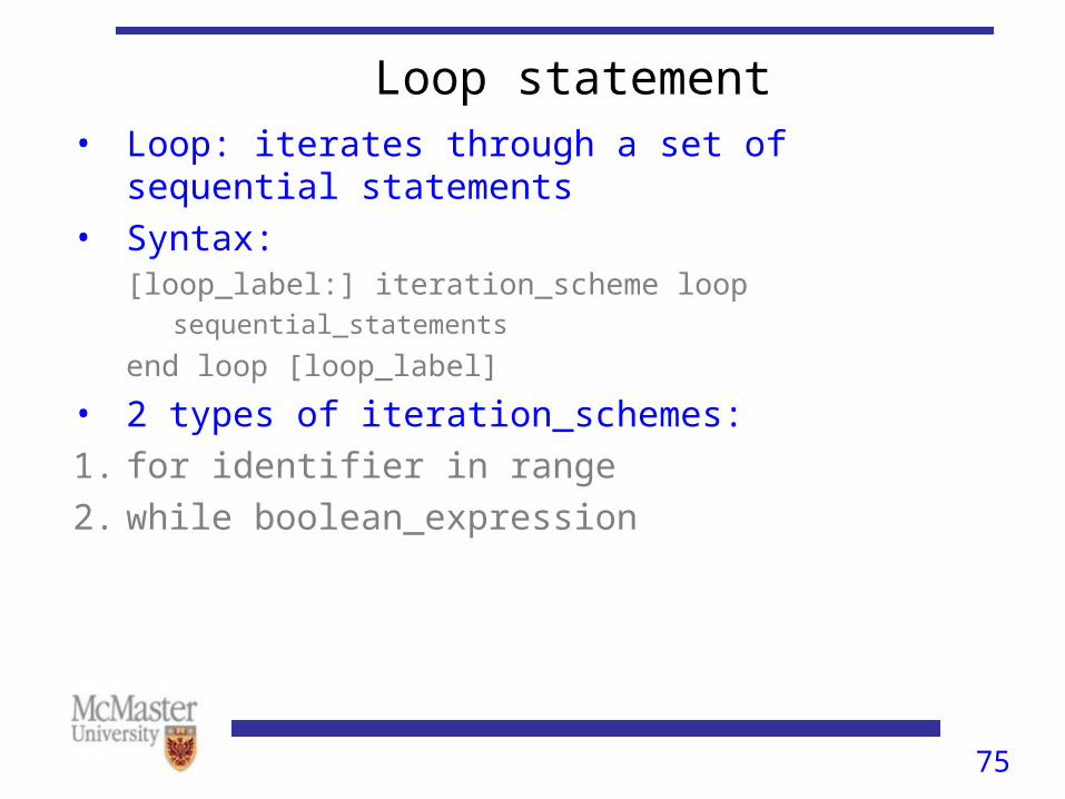
Loop statement• Loop: iterates through a set of sequential statements
• Syntax:[loop_label:] iteration_scheme loop
sequential_statements
end loop [loop_label]
• 2 types of iteration_schemes:
1. for identifier in range
2. while boolean_expression

76
4-bit left-to-right shift register
ENTITY shiftn ISPORT ( R : IN STD_LOGIC_VECTOR(3 DOWNTO 0) ;
Clock : IN STD_LOGIC ;L, w : IN STD_LOGIC ;Q : BUFFER STD_LOGIC_VECTOR(3 DOWNTO 0) ) ;
END shiftn ;ARCHITECTURE Behavior OF shiftn ISBEGIN
PROCESSBEGIN
WAIT UNTIL Clock'EVENT AND Clock = '1' ;IF L = '1' THEN
Q <= R ;ELSE
Genbits: FOR i IN 0 TO 2 LOOPQ(i) <= Q(i+1) ;
END LOOP ;Q(3) <= w ;
END IF ;END PROCESS ;
END Behavior ;
77
Process Statement Execution• A process is either being executed or suspended. It is
executed when one of the signals in its sensitivity list has a change in value.
• A process continues to execute until the last statement is reached and it suspends itself. It is executed again when there is a event on a signal in the sensitivity list.
• A wait statement can also be used to suspend a process. wait statement should either be at the beginning or at the end of a process.