4IPSU 5FDIOJDBM 3FQPSUT in-sheet laser imaging microscopy ...mousecochlea.umn.edu/pubs/Biotechniques...
11
www.BioTechniques.com Vol. | No. | Introduction The ability to selectively visualize three- dimensional (3-D) biological structures is useful for understanding structure, function, and dysfunction relation- ships in tissues and organs, and is one of the initiatives of the National Insti- tutes of Health (NIH) Roadmap for Medical Research. Three-dimensional reconstruction of anatomical structures requires that tissues be sectioned (either mechanically or nondestructively) and structures segmented for 3-D rendering. Nondestructive optical sectioning produces well-aligned sections and can be performed, at high resolution using confocal and multiphoton microscopy, but imaging depth is limited to a few hundred microns. For thick specimens, micro MRI or micro CT can be used, but at lower resolution and without the advantages offered by immunofluores- cence. Light sheet–based microscopy is an important, innovative tool that offers nondestructive optical sectioning of selec- tively stained thick tissues at a spatial resolution between that of micro MRI and confocal microscopy. Development of this technology has been hindered by the lack of a commercial device, although several investigators have constructed light sheet–based microscopes. Optical sectioning using a plane of light was described as early as 1903 by Siedentopf and Zsigmondy (1), but given the unfortunate name of ultramicroscopy, which now refers to electron microscopy. The basis for light-sheet optical sectioning and the materials for the construction of a device are quite simple. A thin light sheet is produced using a cylindrical lens and is projected through either a transparent or fixed and cleared specimen to illuminate a thin plane (i.e., optical section) within the tissue. The optical section is observed orthogonal to the light sheet, and by moving the specimen through the thin plane of light, a z stack of serial sections is produced. Pioneering work on a light sheet microscope was done by Voie et al. (2–4) and called orthogonal-plane fluorescence optical sectioning (OPFOS). Their device collected real-time, 2-D optical sections in cleared tissues using a light sheet that was produced using a single laser, beam expander, and cylin- drical lens. Fuchs et al. (5) constructed a similar device, called thin–light sheet microscopy (TLSM) to optically section specimens in seawater. Another device was developed by Huisken et al. (6) called selective plane illumination microscopy (SPIM). This method rotates an agarose- embedded specimen through a single laser light sheet, but requires complex algorithms to produce a z stack of optical sections. Dodt et al. (7) called their method ultramicroscopy and added dual light sheet illumination for the optical sectioning of larger specimens such as the mouse brain. The quality of the optical sections produced by all of these devices is dependent upon the optical geometry of the light sheet. A light sheet produced by a cylindrical lens has a Gaussian intensity prole and reaches a minimal thickness (called the beam waist) in close proximity to the focal plane of the lens (see Supple- mentary Materials and Supplementary Figure 1 for details). The beam waist has a relatively constant thickness over a region called the confocal parameter, which is also twice the Raleigh range. For small specimens whose dimensions do not exceed the confocal parameter, the optical section appears to have nearly uniform resolution across the width of the specimen. However, for large specimens, optimized resolution and focus is present only in the tissue region illuminated within the confocal parameter of the light sheet. For large specimens and full-frame imaging, one can choose lenses that result in a larger confocal parameter, but this conguration also produces thicker light sheets and lower image resolution. In order to achieve high-resolution across the full width of large specimens, Buytaert and Dirckx (8) moved a specimen through the beam waist and stitched image columns together to produce a high-resolution, well-focused composite image. However, a light sheet–based device has not yet been developed which incorporates the best features of the previous devices (2–8). is study reports on the development of such a device, which is modular and optimized, and called a thin-sheet laser imaging microscope (TSLIM). In addition, we provide details for the construction of a in-sheet laser imaging microscopy for optical sectioning of thick tissues Peter A. Santi 1 , Shane B. Johnson 1 , Matthias Hillenbrand 2 , Patrick Z. GrandPre 1 , Tiffany J. Glass 1 , and James R. Leger 3 1 Department of Otolaryngology, University of Minnesota, Minneapolis, MN, USA, 2 Technische Universität, Ilmenau, Germany, and 3 Electrical and Computer Engineering, University of Minnesota, Minneapolis, MN, USA BioTechniques 46:287-294 (April 2009) doi 10.2144/000113087 Keywords: optical sectioning; light-sheet imaging; 3-D reconstruction Supplementary material for this article is available at www.BioTechniques.com/article/113087. We report the development of a modular and optimized thin-sheet laser imaging microscope (TSLIM) for nondestructive optical sectioning of organisms and thick tissues such as the mouse cochlea, zebrash brain/ inner ear, and rat brain at a resolution that is comparable to wide-eld uo- rescence microscopy. TSLIM optically sections tissue using a thin sheet of light by inducing a plane of uorescence in transparent or xed and cleared tissues. Moving the specimen through the thinnest portion of the light sheet and stitching these image columns together results in optimal resolution and focus across the width of a large specimen. Dual light sheets and aberra- tion-corrected objectives provide uniform section illumination and reduce absorption artifacts that are common in light-sheet microscopy. Construction details are provided for duplication of a TSLIM device by other investigators in order to encourage further use and development of this important technology.
Transcript of 4IPSU 5FDIOJDBM 3FQPSUT in-sheet laser imaging microscopy ...mousecochlea.umn.edu/pubs/Biotechniques...
www.BioTechniques.com287Vol. 46 | No. 4 | 2009
Introduction The ability to selectively visualize three-dimensional (3-D) biological structures is useful for understanding structure, function, and dysfunction relation-ships in tissues and organs, and is one of the initiatives of the National Insti-tutes of Health (NIH) Roadmap for Medical Research. Three-dimensional reconstruction of anatomical structures requires that tissues be sectioned (either mechanically or nondestructively) and structures segmented for 3-D rendering. Nondestructive optica l sectioning produces well-aligned sections and can be performed, at high resolution using confocal and multiphoton microscopy, but imaging depth is limited to a few hundred microns. For thick specimens, micro MRI or micro CT can be used, but at lower resolution and without the advantages offered by immunofluores-cence. Light sheet–based microscopy is
an important, innovative tool that offers nondestructive optical sectioning of selec-tively stained thick tissues at a spatial resolution between that of micro MRI and confocal microscopy. Development of this technology has been hindered by the lack of a commercial device, although several investigators have constructed light sheet–based microscopes.
Optical sectioning using a plane of light was described as early as 1903 by Siedentopf and Zsigmondy (1), but given the unfortunate name of ultramicroscopy, which now refers to electron microscopy. The basis for light-sheet optical sectioning and the materials for the construction of a device are quite simple. A thin light sheet is produced using a cylindrical lens and is projected through either a transparent or fixed and cleared specimen to illuminate a thin plane (i.e., optical section) within the tissue. The optical section is observed orthogonal to the light sheet, and by moving the specimen through the thin
plane of light, a z stack of serial sections is produced. Pioneering work on a light sheet microscope was done by Voie et al. (2–4) and called orthogonal-plane f luorescence optical sectioning (OPFOS). Their device collected real-time, 2-D optical sections in cleared tissues using a light sheet that was produced using a single laser, beam expander, and cylin-drical lens. Fuchs et al. (5) constructed a similar device, called thin–light sheet microscopy (TLSM) to optically section specimens in seawater. Another device was developed by Huisken et al. (6) called selective plane illumination microscopy (SPIM). This method rotates an agarose-embedded specimen through a single laser light sheet, but requires complex algorithms to produce a z stack of optical sections. Dodt et al. (7) called their method ultramicroscopy and added dual light sheet illumination for the optical sectioning of larger specimens such as the mouse brain.
The quality of the optical sections produced by all of these devices is dependent upon the optical geometry of the light sheet. A light sheet produced by a cylindrical lens has a Gaussian intensity pro(le and reaches a minimal thickness (called the beam waist) in close proximity to the focal plane of the lens (see Supple-mentary Materials and Supplementary Figure 1 for details). The beam waist has a relatively constant thickness over a region called the confocal parameter, which is also twice the Raleigh range. For small specimens whose dimensions do not exceed the confocal parameter, the optical section appears to have nearly uniform resolution across the width of the specimen. However, for large specimens, optimized resolution and focus is present only in the tissue region illuminated within the confocal parameter of the light sheet. For large specimens and full-frame imaging, one can choose lenses that result in a larger confocal parameter, but this con(guration also produces thicker light sheets and lower image resolution. In order to achieve high-resolution across the full width of large specimens, Buytaert and Dirckx (8) moved a specimen through the beam waist and stitched image columns together to produce a high-resolution, well-focused composite image. However, a light sheet–based device has not yet been developed which incorporates the best features of the previous devices (2–8). )is study reports on the development of such a device, which is modular and optimized, and called a thin-sheet laser imaging microscope (TSLIM). In addition, we provide details for the construction of a
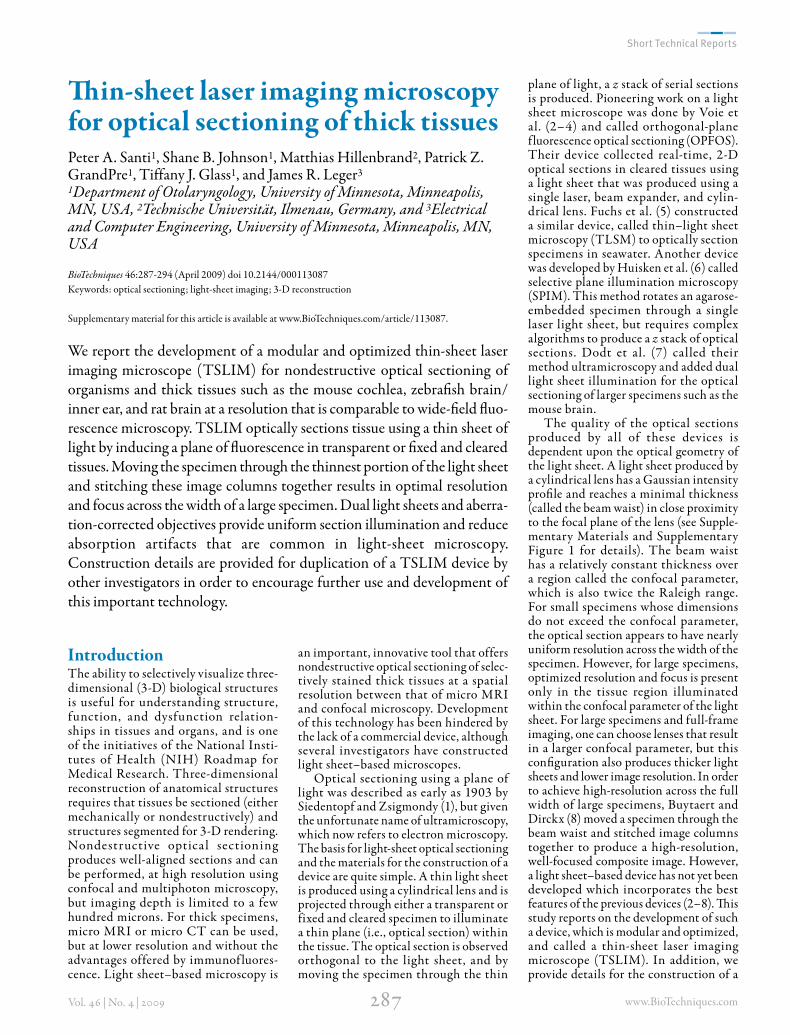
!in-sheet laser imaging microscopy for optical sectioning of thick tissuesPeter A. Santi1, Shane B. Johnson1, Matthias Hillenbrand2, Patrick Z. GrandPre1, Tiffany J. Glass1, and James R. Leger3
1Department of Otolaryngology, University of Minnesota, Minneapolis, MN, USA, 2Technische Universität, Ilmenau, Germany, and 3Electrical and Computer Engineering, University of Minnesota, Minneapolis, MN, USA
BioTechniques 46:287-294 (April 2009) doi 10.2144/000113087 Keywords: optical sectioning; light-sheet imaging; 3-D reconstruction
Supplementary material for this article is available at www.BioTechniques.com/article/113087.
We report the development of a modular and optimized thin-sheet laser imaging microscope (TSLIM) for nondestructive optical sectioning of organisms and thick tissues such as the mouse cochlea, zebra(sh brain/ inner ear, and rat brain at a resolution that is comparable to wide-(eld *uo-rescence microscopy. TSLIM optically sections tissue using a thin sheet of light by inducing a plane of *uorescence in transparent or (xed and cleared tissues. Moving the specimen through the thinnest portion of the light sheet and stitching these image columns together results in optimal resolution and focus across the width of a large specimen. Dual light sheets and aberra-tion-corrected objectives provide uniform section illumination and reduce absorption artifacts that are common in light-sheet microscopy. Construction details are provided for duplication of a TSLIM device by other investigators in order to encourage further use and development of this important technology.
www.BioTechniques.com288Vol. 46 | No. 4 | 2009
TSLIM device by other investigators to encourage its further use and development (see Supplementary Materials).
Materials and methodsAdult CBA/BL6 mice and 5-day-old rat pups were euthanized by CO2 inhalation, decapitated, and mouse cochleas and rat brains were removed and fixed by immersion in 4% paraformaldehyde/1% glutaraldehyde for 24 h. Paraformal-dehyde-(xed Casper mutant zebra(sh (Danio rerio) 6–8 weeks old were shipped to the University of Minnesota for TSLIM imaging. All specimens (except rat brains) were decalcified in a 10% solution of disodium ethylene diaminetetraacetic acid for 3 d and bleached in a 5% solution of H2O2 for 24 h. Mouse cochleas were separated from surrounding tissues and rat brains were hemisected and cut into thirds. )e anterior 5 mm of the zebra(sh head containing the brain and inner ears were used for imaging. All tissues were dehydrated in ascending concentrations of ethanol, immersed in hexane, and then cleared to transparency using Spalteholz *uid (9) which consists of 5:3 methyl salicylate:benzyl benzoate. Rat brains were cleared in 2:1 benzyl benzoate:benzyl alcohol (8) as this solution appeared to clear brain tissue better than Spalteholz *uid. )e refractive index of the cleared specimens and the *uid-(lled specimen chamber was 1.56. Tissue *uorescence, which is necessary for TSLIM imaging, was induced either by chemical (xation autof luorescence (paraformaldehyde/glutaraldehyde), or by immersion in Rhodamine B isothiocyanate (1 mg/200 mL in Spalteholz for 24 h). A 590-nm bandpass (lter was used to block scattered laser light from entering the CCD camera which was used to capture images.
Design and speci(cations of the TSLIM device are shown in computer-aided design (CAD) diagrams (Figure 1, Supplementary Figure 2). TSLIM consists of (ve primary components: two thin-sheet illumi-nators with aberration corrected objec-tives, a specimen chamber, a microscope with digital camera, motorized micropo-sitioners and rotating stage, and control and imaging so+ware. A complete list of materials used for the TSLIM device can be found in Supplementary Table 1 and a parts diagram is outlined in Supple-mentary Figure 2. Assembly and alignment procedures are also available in the Supple-mentary Materials. TSLIM contains two opposing laser illuminators that are mounted on a horizontal optical bench rail, which project their light sheets into
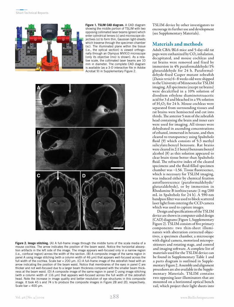
Figure 1. TSLIM CAD diagram. A CAD diagram showing the middle portion of TSLIM with two opposing collimated laser beams (green) which enter cylindrical lenses (c) and microscope ob-jectives (o) to form thin, Gaussian light-sheets which traverse through the specimen chamber (sc). The illuminated plane within the tissue (i.e., the optical section) is viewed orthogo-nally through an Olympus MVX10 microscope [only its objective (mo) is shown]. As a rela-tive scale, the collimated laser beams are 10 mm in diameter. The complete CAD diagram is available (as a 3-D interactive file in Adobe Acrobat 9) in Supplementary Figure 2.
A
B
C D
Figure 2. Image stitching. (A) A full-frame image through the middle turns of the scala media of a mouse cochlea. The arrow indicates the position of the beam waist. Notice the horizontal absorp-tion artifacts in the left side of the image. The image appears well-focused only in a narrow region (i.e., confocal region) across the width of the section. (B) A composite image of the same region in panel A using image stitching (with a column width of 46 µm) that appears well-focused across the full width of the cochlea. Scale bar = 200 µm. (C) A full-frame image of the zebrafish head with an arrow indicating the position of the beam waist. Notice that membranes of the eyes in panel C are thicker and not well-focused due to a larger beam thickness compared with the smaller beam thick-ness at the beam waist. (D) A composite image of the same region in panel C using image stitching (with a column width of 116 µm) that appears well-focused across the full width of the zebrafish head. Note the increase in image quality and better resolution of eye structures in this composite image. It took 45 s and 74 s to produce the composite images in Figure 2B and 2D, respectively. Scale bar = 400 µm.
the specimen chamber. Each illuminator consists of a 15 mW, green (λ = 532 nm) frequency-doubled Nd:YAG laser, a 10× or 20× Galilean beam expander, a cylin-drical lens, and a 5× microscope objective. A 532-nm solid-state laser was selected because it excites and causes emission of a wide variety of *uorescent markers that are used for biological research. )e laser beam is expanded and collimated using a Galilean beam expander, and then travels through a cylindrical lens, which focuses the beam in the y direction. )e cylindrical lens and microscope objective assemble a Keplerian beam expander, which means that the beam leaving the microscope objective is collimated in the y direction. As the cylindrical lens does not a.ect the z component of the beam, the micro-scope objective has a focusing e.ect on the beam that results in a di.raction-limited light-sheet thickness in the z direction. )e improvement in image quality by the addition of an objective lens is shown in Supplementary Figure 3; this was (rst used by Greger et al. (10). )e light sheet then passes through the specimen chamber, which is positioned orthogonal to the optical axis of a horizontally mounted, Olympus MVX10 microscope (Olympus
America, Inc., Center Valley, PA, USA). A glass cuvette or a custom-designed specimen chamber with an open top is (lled with clearing *uid and the specimen is attached to a black Delrin rod (Small Parts Inc., Miramar, FL, USA) that extends into the middle of the chamber. )e specimen attaching rod is connected to an optional, motorized rotating stage for convenient rotation/orientation of the specimen. )e light sheet enters and leaves the chamber through the side windows and the *uorescent image plane in the tissue is viewed through the back window of the chamber nearest the MVX10 objective. Micropositioners (Newport Corp., Irvine, CA, USA) move the specimen (not the chamber) in the x,y,z direc-tions (QImaging, Surrey, BC, Canada) through the illumination plane and at the focal point of the microscope objective. A custom LabVIEW program (version 8.6; National Instruments, Austin, TX, USA) was used to control the micropositioners and collect images using a Retiga 2000 (1600 × 1200 px) digital camera attached to the MVX10 microscope. Microposi-tioner control, image stitching and stack collection were automated and run on a Windows XP–based PC (See program
*owchart in Supplementary Figure 4). )e program controlled x-axis microp-ositioner movement while building a composite image from columns collected at each x-axis step. Column width was chosen to coincide with the confocal parameter of the light sheet and supplied to the CCD camera as a region of interest (ROI). A+er saving each composite image, the z axis was incremented and the next optical section was generated. Images were processed in Adobe Photoshop (Adobe CS3; Adobe Systems Incorporated, San Jose, CA, USA) and ImageJ (version 1.41; National Institutes of Health, Bethesda, MD, USA). After processing, stacks were loaded into Amira so+ware (Visage Imaging Inc., Carlsbad, CA, USA) for reconstruction of individual tissue struc-tures. See Supplementary Materials for information regarding obtaining a copy of our custom LabVIEW program or TSLIM community resources.
Results and discussionTissues from the mouse, zebra(sh, and rat were used to illustrate some of the capabilities of TSLIM. However, TSLIM can be used for optical sectioning of many
Only Semrock offers you a complete range of filters from best value to best performance
– all backed by a five-year warranty.
A Unit of IDEX Corporation
O
www.BioTechniques.com292Vol. 46 | No. 4 | 2009
di.erent types of tissues and organisms. Since TSLIM is modular, it can be con(gured with di.erent lasers, beam expanders, lenses, and specimen chambers for di.erent types of specimens. For high resolution of small structures, a thin beam waist is required and TSLIM could be con(gured for single-beam, full-frame imaging. Exposure times varied depending upon tissue f luorescence, specimen thickness, the number of optical sections desired, and whether single- or dual-beam illumination was used. A typical length of time to obtain a single, full-frame optical section using dual-beam illumination was
1 s. However, for high-resolution struc-tures in a large specimen, a full-frame image would appear focused only within the confocal region of the light sheet. )is is shown in Figure 2 using the mouse cochlea and zebra(sh head. In Figure 2A and 2C the arrow indicates the approximate position of the beam waist and in that region the specimen appears well focused. To the le+ and right of the beam waist, the optical section appears out of focus due to increasing thickness of the light sheet away from the focal point of the lens. To provide
optimal resolution and focus across the full width of a specimen, the specimen was moved across the beam waist of the light sheet and image columns (the size of the confocal region) were obtained and stitched together to form a well focused, composite image (Figure 2, B and D). It took 46 s and 74 s to produce the composite image in Figure 2, B and D, respectively. In addition, horizontal lines are noticeable in the le+ portion of Figure 2A: these are produced by the uneven absorption of light by certain tissue structures as the light passes through the specimen. )ese absorption artifacts, which are common in light-sheet microscopy, are minimized by dual-beam illumination in TSLIM (7,11). Huisken et al. (11) also used beam oscil-lation to reduce absorption lines, but their method required complex equipment and so+ware.
In some specimens that were repeatedly imaged over a period of several months, or exposed to the beam for a long period of time, we noticed a loss in *uorochrome emission (i.e., photobleaching). )is loss was much less than observed in wide-(eld *uorescence microscopy. Photobleaching
in light-sheet microscopy is minimized since only a thin portion of the tissue (i.e., the plane illuminated by the light sheet) is exposed during optical sectioning. In addition, tissue clearing, tissue staining, and the use of a sensitive digital camera requires relatively low-watt light sources (15 mW each) and short exposure times. A preliminary experiment was performed to quantify photobleaching by TSLIM for full-frame and column stitching imaging. In full-frame imaging, tissue was exposed to the light sheet for 1 s or 48 s to produce a composite image by stitching. Pixel intensity decreases were measured in optical sections that were obtained by full-frame versus column stitching. As expected, photobleaching was less a+er a 1-s full-frame image (pixel intensity decrease = 0.85%) compared with a 48-s stitched image (pixel intensity decrease = 8.85%). However, in dye-stained tissue, *uorochrome emission could be restored by restaining the tissue by immersion in Rhodamine B isothiocyanate.
High-magni(cation TSLIM imaging resolves many cellular details within the cochlea. Figure 3A is a 3-D perspective
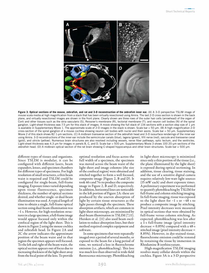
Figure 3. Optical sections of the mouse, zebrafish, and rat and 3-D reconstruction of the zebrafish inner ear. (A) A 3-D perspective TSLIM image of mouse scala media at high magnification from a stack that has been virtually resectioned using Amira. The last 2-D cross section is shown in the back plane, and virtually resectioned images are shown in the front plane. Clearly shown are three rows of the outer hair cells (arrowhead) of the organ of Corti and other tissues such as the stria vascularis (S), Reissner’s membrane (R), tectorial membrane (T), and neuron cell bodies (N) of the spiral ganglion. Light-sheet thickness was 7.5 µm for this stack of images. A movie showing the full stack of 134 sections with a section step size of 1 µm is available in Supplementary Movie 1. The approximate scale of 2-D images in the stack is shown. Scale bar = 50 µm. (B) A high-magnification 2-D cross-section of the spiral ganglion of a mouse cochlea showing neuron cell bodies with nuclei and their axons. Scale bar = 50 µm. Supplementary Movie 2 of this stack shows 82 1-µm sections. (C) A midbrain transverse section of the zebrafish head and 3-D isosurface renderings of the inner ear using Amira. 3-D reconstructions of the inner ear include the semicircular canals (blue), lagena (green), VIII nerve (red), saccule and transverse canal (gold), and utricle (yellow). Numerous brain structures are also resolved including vessels, nerve fiber pathways, optic tectum, and the ventricles. Light-sheet thickness was 4.3 µm for images in panels B, C, and D. Scale bar = 500 µm. Supplementary Movie 3 shows 100 20-µm sections of the zebrafish head. (D) A midbrain optical section of the rat brain showing C-shaped hippocampus and other brain structures. Scale bar = 500 µm.
A B
C D
www.BioTechniques.com294Vol. 46 | No. 4 | 2009
image (using Amira) from a stack of 134 serial TSLIM sections through the mouse cochlea. )e last 2-D section of the stack and virtual, oblique sections through the organ of Corti are shown in this (gure. )ree rows of the outer hair cells and the smaller, single row of pillar cells are clearly visible, as well as a number of other important cochlear structures (e.g., the stria vascularis, tectorial and Reiss-ner’s membranes, and spiral ganglion neurons). A movie (Supplemental Movie 1) of this stack is available in the Supple-mentary Materials. Figure 3B shows an image from a stack of optical sections through the spiral ganglion of another mouse cochlea. )e axons, cell bodies, and nuclei are clearly visible in this (gure and in Supplemental Movie 2, showing 82 1-μm sections of the spiral ganglion (see Supplementary Materials).
TSLIM was also used to image the zebra(sh head. Figure 3C shows imaging of the head of the Casper mutant (12) and 3-D reconstruction of the inner ear using Amira. )e eyes, which contain pigment, were opaque, but other structures such as the brain and membranous labyrinth of the inner ear were clearly resolved in 3-D renderings by Amira, including the semicircular canals, saccule, utricle, lagena, and branches of the VIII nerve. High magni(cation of the brain resolved many structures such as cell bodies, blood vessels, ventricles and nerve (ber pathways that are traceable in a stack of well-aligned serial sections. Supple-mental Movie 3 shows 100 20-μm serial sections through a zebra(sh head. TSLIM imaging was also used to optically section the rat brain. Figure 3D is a cross-section through the rat brain which clearly shows the hippocampus.
Like other light-sheet based devices (2–8,10–11) TSLIM is a powerful imaging technology that permits nondestructive, high-resolution, rapid, and e0cient optical sectioning of thick tissues, whole organs, and even small organisms. TSLIM’s primary advantage over previous systems is that it is modular, optimized, and
incorporates the best features from other designs. It uses o.-the-shelf components and can be constructed for a reasonable cost of $22,000 for a dual-beam system (not including the Olympus microscope and Retiga camera). TSLIM imaging is well-suited for optically sectioning large, (xed, and cleared specimens, and produces a stack of well-aligned images that can be volume-rendered or segmented for isosurface 3-D reconstruction of individual structures. It may also be used for imaging live tissue and organisms in an aqueous solution, provided that they are transparent and contain a f luoro-chrome. )e construction of TSLIM by other investigators will serve to establish the capabilities and limitations of light-sheet based optical sectioning in a variety of di.erent specimens.
Acknowledgments)is work was supported by the Capita Foundation, the Digital Technology Center, and the Supercomputing Institute at the University of Minnesota. It was also supported in part by the National Institute on Deafness and Other Communication Disorders (grant no. RO1 DC007588, to P.S.). We thank Dave Hultman for the construction of custom parts, Richard M. White for generously sending us paraformaldehyde-(xed zebra(sh, and Marilyn Carroll and Justin Anker for providing the rat brains. All authors made signi(cant contributions to this research and the writing of the manuscript. S.J., P.S., and T.G. processed the tissues and prepared the images. S.J. and P.G. wrote the LabVIEW program for specimen movement and image collection. M.H. prepared the CAD design of TSLIM and developed a method to test and align the light sheets. P.S. wrote the manuscript, and J.L. provided expertise on optics selection and measurement. )is paper is subject to the NIH Public Access Policy.
The authors declare no competing interests.
References 1. Siedentopf, H. and R. Zsigmondy. 1903. Über
Sichtbarmachung und Groessenbestimmung ultramikroskopischer Teilchen, mit beson-derer Anwendung auf Goldrubinglaesern. Annalen der Physik 10:1-39.
2. Voie, A.H., D.H. Burns, and F. A. Spelman. 1993. Orthogonal-plane !uores-cence optical sectioning: three-dimensional imaging of macroscopic biological specimens. J. Microsc. 170:229-236.
3. Voie, A.H. and F.A. Spelman. 1995. Three-dimensional reconstruction of the cochlea from two-dimensional images of optical sections. Comput. Med. Imaging Graph. 19:377-384.
4. Voie, A . H . 2 0 02 . I ma g i ng i ntact guinea pig tympanic bulla by orthogonal-plane f luorescence optical sectioning microscopy. Hear. Res. 171:119-128.
5. Fuchs, E., J.S. Ja"e, R.A. Long, and F. Azam. 2002. "in laser light sheet microscope for microbial oceanography. Opt. Express 10:145-154.
6. Huisken, J., J. Swoger, F. Del Bene, J. Wittbrodt, and E.H. Stelzer. 2004. Optical sectioning deep inside live embryos by selective plane illumination microscopy. Science 305:1007-1009.
7. Dodt, H.-U., U. Leischner, A. Schierloh, N. Jährling, C.P. Mauch, K. Deininger, J.M. Deussing, and M. Eder. 2007. Ultrami-croscopy: three-dimensional visualization of neuronal networks in the whole mouse brain. Nat. Methods 4:331-336.
8. Buy taer t, J. A.N. and J.J.J. Dirck x . 2007. Design and quantitative resolution measurements of an optical virtual sectioning three-dimensional imaging technique for biomedical specimens, featuring two-micrometer slicing resolution. Biomed. Opt. 12:014039.1-014039.13.
9. Spalteholz, W. 1914. Über das Durchsich-tigmachen von menschlichen und tierischen Päparaten. S. Hierzel, Leipzig, Germany.
10. Greger, K., Swoger, J., and E. Stelzer. 2007. Basic building units and properties of a !uorescence single plane illumination microscope. Rev. Sci. Instru. 78:023705.1-023705.7.
11. Huisken, J. and D.Y. Stainier. 2007. Even !uorescence excitation by multidirec-tional selective plane illumination microscopy (mSPIM). Opt. Lett. 32:2608-2610.
12. White, R.M., A. Sessa, C. Burke, T. Bowman, J. LeBlanc, C. Ceol, C. Borque, M. Dovey, et al. 2008. Transparent adult zebra#sh as a tool for in vivo transplantation analysis. Cell Stem Cell 2:183-189.
Received 24 September 2008; accepted 17 December 2008.
Address correspondence to Peter A. Santi, Department of Otolaryngology, Room 121, Lions Research Building, 2001 Sixth St. SE, Minneapolis, MN, USA 55455. e-mail: [email protected]
BIOMEDICAL Optics.
800.363.1992 | www.edmundoptics.com
www.BioTechniques.com!Vol. 46 | No. 4 | 2009
LabVIEW program A copy of our custom LabVIEW program for image collection and stitching (for nonpro"t educational use) can be obtained via a Materials Transfer Form from the authors by email at [email protected]. In addition, a web site (http://mousecochlea.umn.edu/TSLIM) has been developed for information exchange between TSLIM users.
Information on opticsLight-sheet formation by a lens (see Supplementary Figure 1)As Gaussian beams have an in"nite intensity distribution, the distance from the optical axis at which the intensity reduces to 1/e2 of the on axis value is usually de"ned as the width of the beam. At the thinnest region of the light sheet this distance is called the beam waist w 0 and its size can be calculated approximately by
0 0
fw w
.
[Eq. S1]
#e thickness of the light sheet grows with increasing distance from the beam waist according to
2
0( ) 1R
x fw x w
x
.
[Eq. S2]
#e Rayleigh range x R is the distance on either side of the beam waist where
the beam width, w (x), has increased to 2 ! w 0:
20
R
wx
.
[Eq. S3]
Twice the Rayleigh range is called the confocal parameter, b , and is a region of the beam where the focal thickness remains approximately constant. A smaller focal length improves axial resolution by producing thinner light sheets, but only over a smaller distance across the illumi-nated plane of the tissue. Paraxial calcu-lations show that the beam waist within the solution is the same as in air, while the Rayleigh range increases by the refractive index of the solution. Diagram and nomen-clature derived from: Siegman, A.E. 1986. Lasers, p.663-671. University Science Books, Sausalito, CA.
Assembly instructions Part numbers correspond with parts listed in Supplementary Table 1 and diagrammed in Supplementary Figure 5.
Step 1: Base With screws from the kit (SK-25A), attach the long optical rail (PRL-36) along the long axis of the aluminum base plate (SL104). Attach the short optical rail (PRL-12) to the base plate, perpendicular to the long optical rail. Mounting the microscope horizontally on the base plate opposite of the short optical rail requires another optical rail, which will depend upon the microscope used.
Step 2: IlluminatorsMount a rail carrier (PRC-3) on the long optical rail. Attach a stage (423) with
adjustment screw (AJS100–1) to the rail carrier such that the stage axis of movement is perpendicular to the axis of the long optical rail. Mount the stage so that it will move in the z axis (see Parts Diagram, Figure S5). Attach another stage (433) on top of the 423 stage such that it will move in the same axis as the long optical rail (x axis on the diagram). To the 433 stage, attach the optical breadboard (MB612). #is requires drilling a new pattern of holes in the bread-board that "t the pattern of the 433 stage. #e breadboard serves as the platform for the optical components. Attach the right angle bracket (NT58–181) to the breadboard and $ush with its back corner. As shown in the diagram, attach a 423 stage with AJS100–1 adjustment screw to the right angle bracket. To this stage attach the optical mount (600A-2R). To the optical mount attach the custom beam expander holder (SL101), into which "ts the beam expander (NT55–579). #e beam expander should be "tted with the rear accessory attachment (NT55–582), which allows the attachment of the laser holder (SL106) and laser (GM32–15H).
After attaching the laser and beam expander, the cylindrical lens is attached. First, attach a post holder base (BA1S) to the breadboard so that it lines up well with the beam expander, but allows enough room for the objective lens (Figure S5). To the BA1S, attach a post holder (PH3-ST) with a post (TR3). To the top of the post, attach the cylindrical lens holder (CYM-2R) and cylindrical lens. Next, attach the BA2T2 post holder to the breadboard (Figure S5). To this, attach a PH3-ST post holder and TR3 post. At the top of the post, attach the compact XYZ stage (MT-XYZ). To this stage attach the kinematic mount (KM200). #e objective lens holder (SL107) is secured in the KM200 into which the objective lens (NT59–876) is mounted.
Step 3: Specimen Chamber SystemBeginning with another PRC-3 rail carrier, attach a 423 stage with AJS100–1
Supplementary Material For:
"in-sheet laser imaging microscopy for optical section-ing of thick tissuesPeter A. Santi1, Shane B. Johnson1, Matthias Hillenbrand2, Patrick Z. GrandPre1, Tiffany J. Glass1, and James R. Leger3
1Department of Otolaryngology, University of Minnesota, Minneapolis, MN, USA, 2Technische Universität, Ilmenau, Germany, and 3Electrical and Computer Engineering, University of Minnesota, Minneapolis, MN, USA
BioTechniques 46:287-294 (April 2009) doi 10.2144/000113087 Keywords: optical sectioning; light-sheet imaging; 3-D reconstruction
www.BioTechniques.com%Vol. 46 | No. 4 | 2009
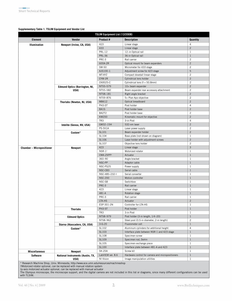
Supplementary Table 1. TSLIM Equipment and Vendor List
TSLIM Equipment List (12/2008)
Element Vendor Product # Description Quantity
Illumination Newport (Irvine, CA, USA) 423 Linear stage 4433 Linear stage 2PRL-12 12–in Optical rail 1PRL-36 36-in Optical rail 1PRC-3 Rail carrier 2600A-2R Optical mount for beam expanders 2SM-50 Micrometer for 433 stage 2AJS100–1 Adjustment screw for 423 stage 5MT-XYZ Compact dovetail linear stage 2CYM-2R Cylindrical lens holder 2CKX525-C Cylindrical lens (f = 50.8mm) 2
Edmund Optics (Barrington, NJ, USA)
NT55–579 10& beam expander 2NT55–582 Beam expander rear accessory attachment 2NT58–181 Right angle bracket 2NT59–876 5& Plan Apo objective 2
Thorlabs (Newton, NJ, USA) MB612 Optical breadboard 2PH3-ST Post holder 4BA1S Post holder base 2BA2T2 Post holder base 2KM200 Kinematic mount for objective 2TR3 3-in Post 4
Intelite (Genoa, NV, USA) GM32–15H 532-nm laser 2PS-5V1A Laser power supply 2
Custom* SL101 Beam expander holder 2SL104 Base plate (not shown on diagram) 1SL106 Laser holder with adjustment screws 2SL107 Objective lens holder 2
Chamber – Micropositioner Newport 423 Linear stage 3NSR-1† Motorized rotator 1CMA-25PP‡ Actuator 1360–90 Angle bracket 1NSC-PP Adaptor cable 1NSC-PS25 Power supply 1NSC-CB3 Serial cable 1NSC-485–232-I Serial converter 1NSC-200 Motion controller 1NSC-SB Switchbox 1PRC-3 Rail carrier 1423 Linear stage 1481-A Rotation stage 1PRC-3 Rail carrier 1LTA-HS Actuator 2ESP-301-2N Controller for LTA-HS 1
Thorlabs PH3-ST Post holder 1TR3 3-in Post 1
Edmund Optics NT58–979 Post holder (3-in length, 1/4–20) 1NT58–962 Steel post (0.5-in diameter, 2-in length) 2
Starna (Atascadero, CA, USA) 3-G-20 Fluorometer cell 1
Custom* SL102 Aluminum cylinders for additional height 4SL103 Interface plate between NSR-1 and 423 stage 1SL108 Specimen screw 1SL109 Specimen rod, Delrin 1SL105 Specimen exchange piece 1SL100 Interface plate between 481-A and 423 1
Miscellaneous Newport SK-25A Screw kit 1
Software National Instruments (Austin, TX, USA)
LabVIEW ver. 8.6 Hardware control for camera and micropositioners 1NI Vision Image manipulation utilities 1
* Research Machine Shop, Univ. Minnesota, http://www.ece.umn.edu/resources/machineshop†Motorized rotator optional, can be replaced with manual rotation system‡y-axis motorized actuator optional, can be replaced with manual actuatorThe Olympus microscope, the microscope support, and the digital camera are not included in this list or diagrams, since many different configurations can be used with TLSIM.
www.BioTechniques.com'Vol. 46 | No. 4 | 2009
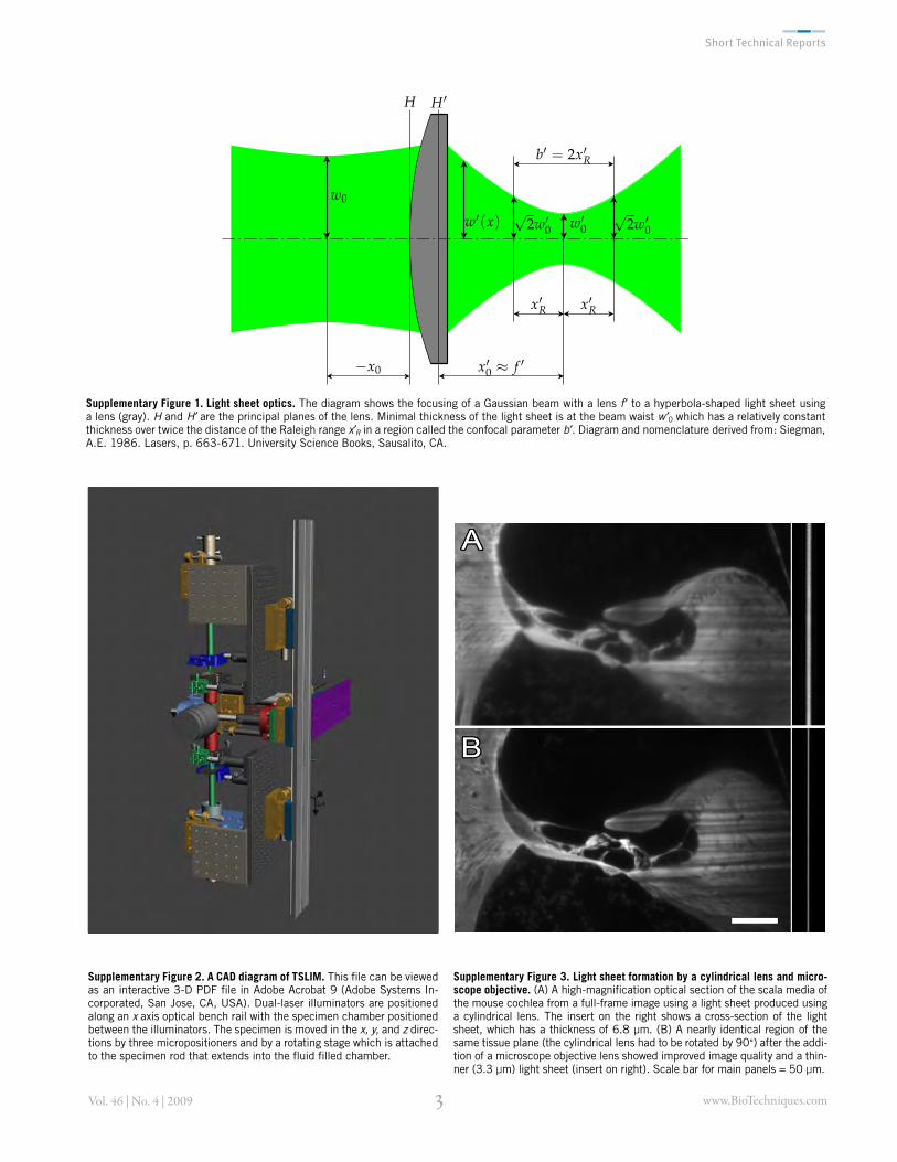
Supplementary Figure 2. A CAD diagram of TSLIM. This file can be viewed as an interactive 3-D PDF file in Adobe Acrobat 9 (Adobe Systems In-corporated, San Jose, CA, USA). Dual-laser illuminators are positioned along an x axis optical bench rail with the specimen chamber positioned between the illuminators. The specimen is moved in the x, y, and z direc-tions by three micropositioners and by a rotating stage which is attached to the specimen rod that extends into the fluid filled chamber.
Supplementary Figure 3. Light sheet formation by a cylindrical lens and micro-scope objective. (A) A high-magnification optical section of the scala media of the mouse cochlea from a full-frame image using a light sheet produced using a cylindrical lens. The insert on the right shows a cross-section of the light sheet, which has a thickness of 6.8 µm. (B) A nearly identical region of the same tissue plane (the cylindrical lens had to be rotated by 90°) after the addi-tion of a microscope objective lens showed improved image quality and a thin-ner (3.3 µm) light sheet (insert on right). Scale bar for main panels = 50 µm.
Supplementary Figure 1. Light sheet optics. The diagram shows the focusing of a Gaussian beam with a lens f to a hyperbola-shaped light sheet using a lens (gray). H and H are the principal planes of the lens. Minimal thickness of the light sheet is at the beam waist w 0 which has a relatively constant thickness over twice the distance of the Raleigh range x R in a region called the confocal parameter b . Diagram and nomenclature derived from: Siegman, A.E. 1986. Lasers, p. 663-671. University Science Books, Sausalito, CA.
www.BioTechniques.com(Vol. 46 | No. 4 | 2009
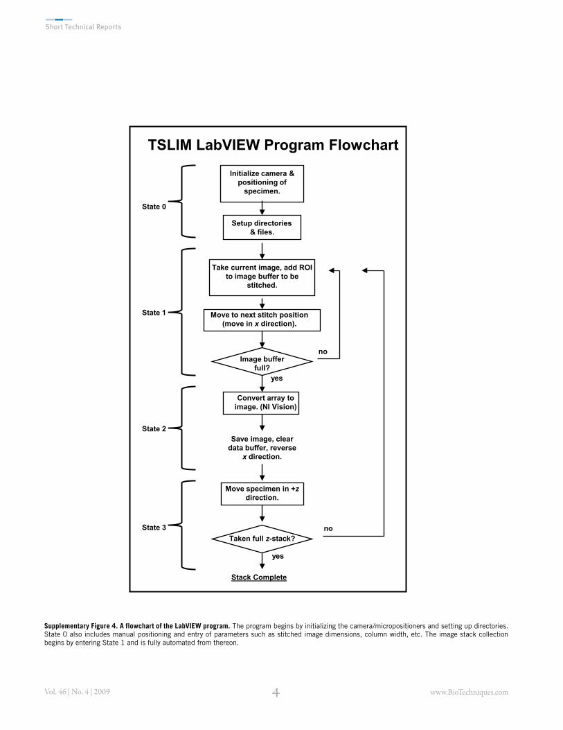
Supplementary Figure 4. A flowchart of the LabVIEW program. The program begins by initializing the camera/micropositioners and setting up directories. State 0 also includes manual positioning and entry of parameters such as stitched image dimensions, column width, etc. The image stack collection begins by entering State 1 and is fully automated from thereon.
Initialize camera & positioning of
specimen.
Take current image, add ROI to image buffer to be
stitched.
Move to next stitch position (move in x direction).
Image buffer full?
no
yes
Save image, clear data buffer, reverse
x direction.
Move specimen in +z direction.
noTaken full z-stack?
yes
State 0
State 1
State 2
TSLIM LabVIEW Program Flowchart
State 3
Convert array to image. (NI Vision)
Setup directories & files.
Stack Complete
www.BioTechniques.com)Vol. 46 | No. 4 | 2009
adjustment screw. Above this, attach the SL100 interface plate. Add a PH3-ST post holder with TR3 post to the 481-A, and screw the 481-A down to the interface plate. Glue the specimen chamber (3-G-20) to the post. Put this assembly on the long optical rail between the illuminators.
Step 4: Micropositioner SystemPlace a PRC-3 rail carrier on the short optical rail. To this attach two 423 stages with CMA-25PP motorized actuators in an x/y stack. To get the specimen up to the height of the rest of the system it is necessary to next attach 4 aluminum cylinders to the x/y stack and to these cylinders the 360–90 angle bracket. To the angle bracket attach the SL103 interface plate, which allows minor adjustments and the attachment of the NSR-1 rotator. A*er removing the plug from the ring of the NSR-1, it is possible to add the specimen exchange piece (SL105), specimen screw (SL108), and specimen rod (SL109).
TSLIM Alignment ProcedurePart numbers correspond with parts listed in Supplementary Table 1 and diagrammed in Supplementary Figure 5.
!in Sheet Laser Imaging Microscope Alignment (see Figure S5 for part labels)#e "rst four steps are performed without cylindrical lens, microscope objectives, or chamber.
1. Alignment of the cameraUsing a level, rotate the camera until it is horizontal.
2. Alignment of laser and beam expanderPlace a white sheet of paper at a distance of about 10 cm in front of the beam expander. Turn the screws holding the laser (SL106) until the image of the laser beam on the sheet of paper is rotationally symmetric. It is important to visualize the beam at highest intensity because its direction changes as the power increases.
3. Adjustment of the Edmund’s Galilean beam expanderPosition a plane parallel glass plate behind the beam expander and rotate this glass plate about 45 degrees in order to create a interference pattern which can be visualized with a white sheet of paper in the direction of the re$ection. Adjust the beam expander collar (NT55–579) until only 0–1 interference fringes are visible to collimate the beam.
4. Adjustment of the expanded laser beam parallel to the base rail and to the correct height.Move an aperture or a comparable object attached to a carrier along the rail and tilt the beam expander group (laser and attached beam expander) until the image of the laser beam on the aperture is stationary along the length of the rail (parallel to the
rail). Adjust the height of the collimated beam to the height of the microscope.
5. Adjustment of the lateral position of the microscope objective (NT59–876)Insert the microscope objective (NT59–876). Adjust y and z position of the micro-scope objective with the linear stages (MT-XYZ) in order to align it coaxially to the collimated laser beam.
6. Adjustment of the cylindrical lensInsert the cylindrical lens. Adjust the post holding the lens (PH3-ST) to the right height and tighten the screw on the post holder. Adjust the distance between the cylindrical lens and the microscope objective to the position where the beam leaving the microscope objective is colli-mated in the y direction (fine adjust-ments can be done with the linear stage (MT-XYZ). Rotate the cylindrical lens until the light sheet leaving the illumi-nation objective is perpendicular to the optical axis of the main microscope.
7. Fine adjustment of the light sheetLaser intensity is attenuated by one neutral density "lter, protecting the CCD from damage. Put a mirror in the place of the specimen chamber to ref lect the laser beam into the imaging microscope. Tilt the microscope objective (NT59–876) with the kinematic mount (KM200) in order to get the best possible light sheet thickness by reducing side lobes (the light sheet should be symmetrical).
8. Alignment of the specimen chamberInsert the specimen chamber. Position the specimen chamber near the microscope objective. Rotate the chamber so that it is square to the objective of the imaging microscope.
9. Alignment of the two beamsA*er lens alignment, the beams will be parallel but not coincident. #e beams can be aligned by looking at a stained specimen placed in the specimen chamber. Replace the neutral density "lter with a bandpass "lter transmitting the light emitted by the specimen. Focus the imaging micro-scope on one of the two light sheets. #e beam waist can be recognized by the area with the highest resolution and should be positioned close to the center of the imaging microscope by the linear stage (433). Focus the imaging microscope on the other light sheet and redo the focusing step. In order to make both beams coincident, adjust the z position of one of the two light sheets with the linear stage (423).placed in the specimen chamber. Replace the neutral density "lter with a bandpass "lter trans-
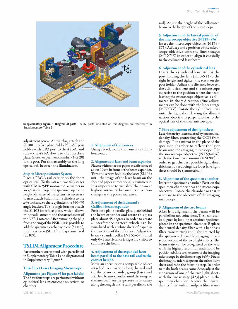
Supplementary Figure 5. Diagram of parts. TSLIM parts indicated on this diagram are referred to in Supplementary Table 1.
www.BioTechniques.com+Vol. 46 | No. 4 | 2009
mitting the light emitted by the specimen. Focus the imaging microscope on one of the two light sheets. #e beam waist can be recognized by the area with the highest resolution and should be positioned close to the center of the imaging microscope by the linear stage (433). Focus the imaging microscope on the other light sheet and redo the focusing step. In order to make both beams coincident, adjust the z position of one of the two light sheets with the linear stage (423).