4.ECE2 CN - UNIT - I : INTRODUCTION
24
4.ECE2 CN - UNIT - I : INTRODUCTION During the 20th century, the key technology was information gathering, processing, and distribution. The merging of computers and communications has had a profound influence on the way computer systems are organized. The concept of the ''computer center'' as a room with a large computer to which users bring their work for processing is now totally obsolete. The old model of a single computer serving all of the organization's computational needs has been replaced by one in which a large number of separate but interconnected computers do the job. These systems are called computer networks. A network is a set of devices (often referred to as nodes) connected by communication links. A node can be a computer, printer, or any other device capable of sending and/or receiving data generated by other nodes on the network Definition: The term ''computer network '' to mean a collection of autonomous computers interconnected by a single technology. Two computers are said to be interconnected if they are able to exchange information. The connection need not be via a copper wire; fiber optics, microwaves, infrared, and communication satellites can also be used. Networks come in many sizes, shapes and forms. There is considerable confusion in the literature between a computer network and a distributed system. Definition: The key distinction is that in a distributed system, a collection of independent computers appears to its users as a single coherent system. A data communications system has five components. 1. Message. The message is the information (data) to be communicated. Popular forms of information include text, numbers, pictures, audio, and video. 2. Sender . The sender is the device that sends the data message. It can be a computer, workstation, telephone handset, video camera, and so on. 3. Receiver . The receiver is the device that receives the message. It can be a computer, workstation, telephone handset, television, and so on.
Transcript of 4.ECE2 CN - UNIT - I : INTRODUCTION

4.ECE2 CN - UNIT - I :
INTRODUCTION During the 20th century, the key technology was information gathering, processing, and
distribution. The merging of computers and communications has had a profound
influence on the way computer systems are organized. The concept of the ''computer
center'' as a room with a large computer to which users bring their work for processing is
now totally obsolete. The old model of a single computer serving all of the organization's
computational needs has been replaced by one in which a large number of separate but
interconnected computers do the job. These systems are called computer networks.
A network is a set of devices (often referred to as nodes) connected by communication
links. A node can be a computer, printer, or any other device capable of sending and/or
receiving data generated by other nodes on the network
Definition:
The term ''computer network'' to mean a collection of autonomous computers
interconnected by a single technology. Two computers are said to be interconnected if
they are able to exchange information. The connection need not be via a copper wire;
fiber optics, microwaves, infrared, and communication satellites can also be used.
Networks come in many sizes, shapes and forms.
There is considerable confusion in the literature between a computer network and a
distributed system.
Definition:
The key distinction is that in a distributed system, a collection of independent computers
appears to its users as a single coherent system.
A data communications system has five components.
1. Message. The message is the information (data) to be
communicated. Popular forms of information include text,
numbers, pictures, audio, and video.
2. Sender. The sender is the device that sends the data
message. It can be a computer, workstation, telephone handset,
video camera, and so on.
3. Receiver. The receiver is the device that receives the message.
It can be a computer, workstation, telephone handset, television,
and so on.

4. Transmission medium. The transmission medium is the
physical path by which a message travels from sender to receiver.
Some examples of transmission media include twisted-pair wire,
coaxial cable, fiber-optic cable, and radio waves
5. Protocol. A protocol is a set of rules that govern data
communications. It represents an agreement between the
communicating devices. Without a protocol, two devices may be
connected but not communicating, just as a person speaking
French cannot be understood by a person who speaks only
Japanese.
1.1 Uses of Computer Networks
1.1.1 Business Applications
The issue here is resource sharing, and the goal is to make all programs, equipment, and
especially data available to anyone on the network without regard to the physical location
of the resource and the user. In the simplest of terms, one can imagine a company's
information system as consisting of one or more databases and some number of
employees who need to access them remotely. In this model, the data are stored on
powerful computers called servers. Often these are centrally housed and maintained by a
system administrator. In contrast, the employees have simpler machines, called clients,
on their desks, with which they access remote data, for example, to include in
spreadsheets they are constructing. The client and server machines are connected by a
network, as illustrated in Fig. 1-1.
Figure 1-1. A network with two clients and one server
Figure 1-2. The client-server model involves requests and replies.
In client-server model Communication takes the form of the client process sending a
message over the network to the server process. The client process then waits for a reply
message. When the server process gets the request, it performs the requested work or
looks up the requested data and sends back a reply. These messages are shown in Fig. 1-2.
A second goal of setting up a computer network has to do with people rather than
information or even computers. A computer network can provide a powerful

communication medium among employees. Virtually every company that has two or
more computers now has e-mail (electronic mail), which employees generally use for a
great deal of daily communication. But e-mail is not the only form of improved
communication made possible by computer networks. With a network, it is easy for two
or more people who work far apart to write a report together. When one worker makes a
change to an online document, the others can see the change immediately, instead of
waiting several days for a letter. Such a speedup makes cooperation among far-flung
groups of people easy where it previously had been impossible. another form of
computer-assisted communication is videoconferencing. Using this technology,
employees at distant locations can hold a meeting, seeing and hearing each other and
even writing on a shared virtual blackboard. Videoconferencing is a powerful tool for
eliminating the cost and time previously devoted to travel.
A third goal for increasingly many companies is doing business electronically with other
companies, especially suppliers and customers. For example, manufacturers of
automobiles, aircraft, and computers, among others, buy subsystems from a variety of
suppliers and then assemble the parts. Using computer networks, manufacturers can place
orders electronically as needed. Being able to place orders in real time (i.e., as needed)
reduces the need for large inventories and enhances efficiency. A fourth goal that is
starting to become more important is doing business with consumers over the Internet.
Airlines, bookstores, and music vendors have discovered that many customers like the
convenience of shopping from home.
1.1.2 Home Applications
Uses of the Internet for home users are :
1. Access to remote information. 2. Person-to-person communication.
3. Interactive entertainment. 4. Electronic commerce.
Person-to-person communication often goes by the name of peer-to-peer communication,
to distinguish it from the client-server model. In this form, individuals who form a loose
group can communicate with others in the group, as shown in Fig. 1-3. Every person can,
in principle, communicate with one or more other people; there is no fixed division into
clients and servers.
Figure 1-3. In a peer-to-peer system there are no fixed clients and servers. On-line auctions are more of a peer-to-peer system, sort of consumer-to-consumer. Some
of these forms of e-commerce have acquired cute little tags.

Figure 1-4. Some forms of e-commerce. 1.1.3 Mobile Users
Mobile computers, such as notebook computers and personal digital assistants (PDAs),
are one of the fastest-growing segments of the computer industry. Many owners of these
computers have desktop machines back at the office and want to be connected to their
home base even when away from home or en route. People on the road often want to use
their portable electronic equipment to send and receive telephone calls, faxes, and
electronic mail, surf the Web, access remote files, and log on to remote machines. And
they want to do this from anywhere on land, sea, or air. Wireless networks are also
important to the military. wireless networking and mobile computing are often related,
they are not identical, as
Figure 1-5. Combinations of wireless networks and mobile computing.
1.1.4 Social Issues
The widespread introduction of networking has introduced new social, ethical, and
political problems.
1.2 Network Hardware
There are two types of transmission technology
1. Broadcast links. 2. Point-to-point links.
Broadcast networks have a single communication channel that is shared by all the
machines on the network. Short messages, called packets in certain contexts, sent by any
machine are received by all the others. An address field within the packet specifies the
intended recipient. Upon receiving a packet, a machine checks the address field. If the
packet is intended for the receiving machine, that machine processes the packet; if the
packet is intended for some other machine, it is just ignored. Broadcast systems generally
also allow the possibility of addressing a packet to all destinations by using a special
code in the address field. When a packet with this code is transmitted, it is received and
processed by every machine on the network. This mode of operation is called
broadcasting. Some broadcast systems also support transmission to a subset of the
machines, something known as multicasting.
In contrast, point-to-point networks consist of many connections between individual
pairs of machines. To go from the source to the destination, a packet on this type of
network may have to first visit one or more intermediate machines. Often multiple routes,
of different lengths, are possible, so finding good ones is important in point-to-point
networks. As a general rule, smaller, geographically localized networks tend to use
broadcasting, whereas larger networks usually are point-to-point. Point-to-point

transmission with one sender and one receiver is sometimes called unicasting. criterion
for classifying networks is their scale. In Fig. 1-6 we classify multiple processor systems
by their physical size. At the top are the personal area networks, networks that are
meant for one person. For example, a wireless network connecting a computer with its
mouse, keyboard, and printer is a personal area network. Also, a PDA that controls the
user's hearing aid or pacemaker fits in this category. Beyond the personal area networks
come longer-range networks. These can be divided into local, metropolitan, and wide
area networks. Finally, the connection of two or more networks is called an internetwork.
The worldwide Internet is a well-known example of an internetwork. Distance is
important as a classification metric because different techniques are used at different
scales.
Figure 1-6. Classification of interconnected processors by scale.
1.2.1 Local Area Networks ( LAN )
Local area networks, generally called LANs, are privately-owned networks within a
single building or campus of up to a few kilometers in size. They are widely used to
connect personal computers and workstations in company offices and factories to share
resources (e.g., printers) and exchange information. LANs are distinguished from other
kinds of networks by three characteristics: (1) their size, (2) their transmission technology,
and (3) their topology.
LANs are restricted in size, which means that the worst-case transmission time is
bounded and known in advance. Knowing this bound makes it possible to use certain
kinds of designs that would not otherwise be possible. It also simplifies network
management. LANs may use a transmission technology consisting of a cable to which all
the machines are attached, like the telephone company party lines once used in rural areas.
Traditional LANs run at speeds of 10 Mbps to 100 Mbps, have low delay (microseconds
or nanoseconds), and make very few errors. Newer LANs operate at up to 10 Gbps. In
this book, we will adhere to tradition and measure line speeds in megabits/sec (1 Mbps is
1,000,000 bits/sec) and gigabits/sec (1Gbps is 1,000,000,000 bits/sec). Various
topologies are possible for broadcast LANs. Figure 1-7
In a bus (i.e., a linear cable) network, at any instant at most one machine is the master and
is allowed to transmit. All other machines are required to refrain from sending. An
arbitration mechanism is needed to resolve conflicts when two or more machines want to
transmit simultaneously. The arbitration mechanism may be centralized or distributed.
IEEE 802.3, popularly called Ethernet, for example, is a bus-based broadcast network

with decentralized control, usually operating at 10 Mbps to 10 Gbps. Computers on an
Ethernet can transmit whenever they want to; if two or more packets collide, each
computer just waits a random time and tries again later.
Figure 1-7. Two broadcast networks. (a) Bus. (b) Ring.
A second type of broadcast system is the ring. In a ring, each bit propagates around on its
own, not waiting for the rest of the packet to which it belongs. Typically, each bit
circumnavigates the entire ring in the time it takes to transmit a few bits, often before the
complete packet has even been transmitted. As with all other broadcast systems, some
rule is needed for arbitrating simultaneous accesses to the ring. Various methods, such as
having the machines take turns, are in use. IEEE 802.5 (the IBM token ring), is a ring-
based LAN operating at 4 and 16 Mbps. FDDI is another example of a ring network.
Broadcast networks can be further divided into static and dynamic, depending on how the
channel is allocated. A typical static allocation would be to divide time into discrete
intervals and use a round-robin algorithm, allowing each machine to broadcast only when
its time slot comes up. Static allocation wastes channel capacity when a machine has
nothing to say during its allocated slot, so most systems attempt to allocate the channel
dynamically (i.e., on demand).
Dynamic allocation methods for a common channel are either centralized or
decentralized. In the centralized channel allocation method, there is a single entity, for
example, a bus arbitration unit, which determines who goes next. It might do this by
accepting requests and making a decision according to some internal algorithm. In the
decentralized channel allocation method, there is no central entity; each machine must
decide for itself whether to transmit. You might think that this always leads to chaos, but
it does not.
1.2.2 Metropolitan Area Networks ( MAN )
A metropolitan area network, or MAN, covers a city. The best-known example of a
MAN is the cable television network available in many cities. This system grew from
earlier community antenna systems used in areas with poor over-the-air television
reception. MAN might look like the system shown in Fig. 1-8. In this figure we see both
television signals and Internet being fed into the centralized head end for subsequent
distribution to people's homes. Cable television is not the only MAN. Recent
developments in high-speed wireless Internet access resulted in another MAN, which has
been standardized as IEEE 802.16.
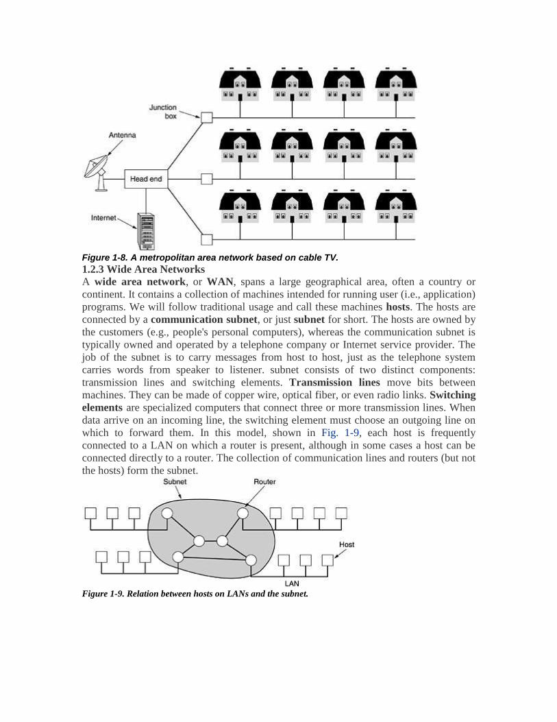
Figure 1-8. A metropolitan area network based on cable TV.
1.2.3 Wide Area Networks
A wide area network, or WAN, spans a large geographical area, often a country or
continent. It contains a collection of machines intended for running user (i.e., application)
programs. We will follow traditional usage and call these machines hosts. The hosts are
connected by a communication subnet, or just subnet for short. The hosts are owned by
the customers (e.g., people's personal computers), whereas the communication subnet is
typically owned and operated by a telephone company or Internet service provider. The
job of the subnet is to carry messages from host to host, just as the telephone system
carries words from speaker to listener. subnet consists of two distinct components:
transmission lines and switching elements. Transmission lines move bits between
machines. They can be made of copper wire, optical fiber, or even radio links. Switching
elements are specialized computers that connect three or more transmission lines. When
data arrive on an incoming line, the switching element must choose an outgoing line on
which to forward them. In this model, shown in Fig. 1-9, each host is frequently
connected to a LAN on which a router is present, although in some cases a host can be
connected directly to a router. The collection of communication lines and routers (but not
the hosts) form the subnet.
Figure 1-9. Relation between hosts on LANs and the subnet.

1.2.4 Wireless Area Networks (WAN )
wireless networks can be divided into three main categories:
1. System interconnection. 2. Wireless LANs. 3. Wireless WANs.
System interconnection is all about interconnecting the components of a computer using
shortrange radio. Almost every computer has a monitor, keyboard, mouse, and printer
connected to the main unit by cables. system interconnection networks use the master-
slave paradigm of Fig. 1- 10(a). The system unit is normally the master, talking to the
mouse, keyboard, etc., as slaves. The master tells the slaves what addresses to use, when
they can broadcast, how long they can transmit, what frequencies they can use, and so on.
Figure 1-10. (a) Bluetooth configuration. (b) Wireless LAN.
The next step up in wireless networking is the wireless LANs. These are systems in
which every computer has a radio modem and antenna with which it can communicate
with other systems. Often there is an antenna on the ceiling that the machines talk to, as
shown in Fig. 1-10(b). However, if the systems are close enough, they can communicate
directly with one another in a peer-to-peer configuration. Wireless LANs are becoming
increasingly common in small offices and homes, where installing Ethernet is considered
too much trouble, as well as in older office buildings, company cafeterias, conference
rooms, and other places. There is a standard for wireless LANs, called IEEE 802.11,
which most systems implement and which is becoming very widespread. The third kind
of wireless network is used in wide area systems. The radio network used for cellular
telephones is an example of a low-bandwidth wireless system. This system has already
gone through three generations. The first generation was analog and for voice only. The
second generation was digital and for voice only. The third generation is digital and is for
both voice and data.
1.2.5 Home Networks
The fundamental idea is that in the future most homes will be set up for networking.
Every device in the home will be capable of communicating with every other device, and
all of them will be accessible over the Internet. Many devices are capable of being
networked. Some of the categories (with examples) are as follows:
1. Computers (desktop PC, notebook PC, PDA, shared peripherals).
2. Entertainment (TV, DVD, VCR, camcorder, camera, stereo, MP3).
3. Telecommunications (telephone, mobile telephone, intercom, fax).
4. Appliances (microwave, refrigerator, clock, furnace, airco, lights).
5. Telemetry (utility meter, smoke/burglar alarm, thermostat, babycam).

1.2.6 Internetworks
A collection of interconnected networks is called an internetwork or internet. A
common form of internet is a collection of LANs connected by a WAN Subnets,
networks, and internetworks are often confused. Subnet makes the most sense in the
context of a wide area network, where it refers to the collection of routers and
communication lines owned by the network operator. An internetwork is formed when
distinct networks are interconnected. In our view, connecting a LAN and a WAN or
connecting two LANs forms an internetwork.
1.3 Network Software
1.3.1 Protocol Hierarchies
Networks are organized as a stack of layers or levels, each one built upon the one below
it. The number of layers, the name of each layer, the contents of each layer, and the
function of each layer differ from network to network. The purpose of each layer is to
offer certain services to the higher layers, shielding those layers from the details of how
the offered services are actually implemented. In a sense, each layer is a kind of virtual
machine, offering certain services to the layer above it. Layer n on one machine carries
on a conversation with layer n on another machine. The rules and conventions used in
this conversation are collectively known as the layer n protocol.
Basically, a protocol is an agreement between the communicating parties on how
Communication is to proceed. A five-layer network is illustrated in Fig. 1-11. The entities
comprising the corresponding layers on different machines are called peers. The peers
may be processes, hardware devices, or even human beings. In other words, it is the peers
that communicate by using the protocol.
Figure 1-11. Layers, protocols, and interfaces.
In reality, no data are directly transferred from layer n on one machine to layer n on
another machine. Instead, each layer passes data and control information to the layer
immediately below it, until the lowest layer is reached. Below layer 1 is the physical
medium through which actual communication occurs. In Fig. 1-11, virtual
communication is shown by dotted lines and physical communication by solid lines.

Between each pair of adjacent layers is an interface. The interface defines which
primitive operations and services the lower layer makes available to the upper one.
A set of layers and protocols is called a network architecture. The specification of an
architecture must contain enough information to allow an implementer to write the
program or build the hardware for each layer so that it will correctly obey the appropriate
protocol. A list of protocols used by a certain system, one protocol per layer, is called a
protocol stack.
Figure 1-12. Example information flow supporting virtual communication in layer 5.
A message, M, is produced by an application process running in layer 5 and given to
layer 4 for transmission. Layer 4 puts a header in front of the message to identify the
message and passes the result to layer 3. The header includes control information, such as
sequence numbers, to allow layer 4 on the destination machine to deliver messages in the
right order if the lower layers do not maintain sequence. In some layers, headers can also
contain sizes, times, and other control fields.
In many networks, there is no limit to the size of messages transmitted in the layer 4
protocol, but there is nearly always a limit imposed by the layer 3 protocol. Consequently,
layer 3 must break up the incoming messages into smaller units, packets, prepending a
layer 3 header to each packet. In this example, M is split into two parts, M1 and M2.
Layer 3 decides which of the outgoing lines to use and passes the packets to layer 2.
Layer 2 adds not only a header to each piece, but also a trailer, and gives the resulting
unit to layer 1 for physical transmission. At the receiving machine the message moves
upward, from layer to layer, with headers being stripped off as it progresses. None of the
headers for layers below n are passed up to layer n. The important thing to understand
about Fig. 1-12 is the relation between the virtual and actual communication and the
difference between protocols and interfaces. The peer processes in layer 4, for example,
conceptually think of their communication as being ''horizontal,'' using the layer 4
protocol. Each one is likely to have a procedure called something like SendToOtherSide
and GetFromOtherSide, even though these procedures actually communicate with lower
layers across the 3/4 interface, not with the other side.

1.3.2 Design Issues for the Layers
Every layer needs a mechanism for identifying senders and receivers. Since a network
normally has many computers, some of which have multiple processes, a means is
needed for a process on one machine to specify with whom it wants to talk. As a
consequence of having multiple destinations, some form of addressing is needed in order
to specify a specific destination.
Another design decision concerns with the rules for data transfer. In some systems,
data only travel in one direction; in others, data can go both ways. The protocol must also
determine how many logical channels the connection corresponds to and what their
priorities are. Many networks provide at least two logical channels per connection, one
for normal data and one for urgent data.
Error control is an important issue because physical communication circuits are not
perfect. Many error-detecting and error-correcting codes are known, but both ends of the
connection must agree on which one is being used. In addition, the receiver must have
some way of telling the sender which messages have been correctly received and which
have not.
An issue that occurs at every level is how to keep a fast sender from swamping a slow
receiver with data. Various solutions have been proposed and will be discussed later.
Some of them involve some kind of feedback from the receiver to the sender, either
directly or indirectly, about the receiver's current situation. Others limit the sender to an
agreed-on transmission rate. This subject is called as flow control.
When there are multiple paths between source and destination, a route must be chosen.
Sometimes this decision must be split over two or more layers. Then a low-level decision
might have to made to select one of the available circuits based on the current traffic load
called routing.
1.3.3 Connection-Oriented and Connectionless Services
Layers can offer two different types of service to the layers above them: connection
oriented and connectionless.
Connection-oriented service is modeled after the telephone system. To talk to someone,
you pick up the phone, dial the number, talk, and then hang up. Similarly, to use a
connection oriented network service, the service user first establishes a connection, uses
the connection, and then releases the connection. The essential aspect of a connection is
that it acts like a tube: the sender pushes objects (bits) in at one end, and the receiver
takes them out at the other end. In most cases the order is preserved so that the bits arrive
in the order they were sent.
In contrast to this, connectionless service is modeled after the postal system. Each
message (letter) carries the full destination address, and each one is routed through the
system independent of all the others. Normally, when two messages are sent to the same
destination, the first one sent will be the first one to arrive. However, it is possible that

the first one sent can be delayed so that the second one arrives first. Each service can be
characterized by a quality of service. Some services are reliable in the sense that they
never lose data. Usually, a reliable service is implemented by having the receiver
acknowledge the receipt of each message so the sender is sure that it arrived. The
acknowledgement process introduces overhead and delays, which are often worth it but
are sometimes undesirable.
Unreliable (meaning not acknowledged) connectionless service is often called datagram
service, in analogy with telegram service, which also does not return an
acknowledgement to the sender.
Figure 1-13. Six different types of service.
1.3.4 Service Primitives
A service is formally specified by a set of primitives (operations) available to a user
process to access the service. These primitives tell the service to perform some action or
report on an action taken by a peer entity. If the protocol stack is located in the operating
system, as it often is, the primitives are normally system calls. These calls cause a trap to
kernel mode, which then turns control of the machine over to the operating system to
send the necessary packets. The set of primitives available depends on the nature of the
service being provided. The primitives for connection-oriented service are different from
those of connectionless service.
Figure 1-14. Five service primitives for implementing a simple connection-oriented service.
First, the server executes LISTEN to indicate that it is prepared to accept incoming
connections. A common way to implement LISTEN is to make it a blocking system call.
After executing the primitive, the server process is blocked until a request for connection
appears.
Next, the client process executes CONNECT to establish a connection with the server.
The CONNECT call needs to specify who to connect to, so it might have a parameter
giving the server's address. The operating system then typically sends a packet to the peer
asking it to connect, as shown by (1) in Fig. 1-15. The client process is suspended until
there is a response. When the packet arrives at the server, it is processed by the operating
system there. When the system sees that the packet is requesting a connection, it checks
to see if there is a listener. If so, it does two things: unblocks the listener and sends back

an acknowledgement (2). The arrival of this acknowledgement then releases the client. At
this point the client and server are both running and they have a connection established. It
is important to note that the acknowledgement (2) is generated by the protocol code itself,
not in response to a user-level primitive. If a connection request arrives and there is no
listener, the result is undefined.
In some systems the packet may be queued for a short time in anticipation of a LISTEN.
Figure 1-15. Packets sent in a simple client-server interaction on a connection-oriented network.
The next step is for the server to execute RECEIVE to prepare to accept the first request.
Normally, the server does this immediately upon being released from the LISTEN, before
the acknowledgement can get back to the client. The RECEIVE call blocks the server.
Then the client executes SEND to transmit its request (3) followed by the execution of
RECEIVE to get the reply. The arrival of the request packet at the server machine
unblocks the server process so it can process the request. After it has done the work, it
uses SEND to return the answer to the client (4). The arrival of this packet unblocks the
client, which can now inspect the answer. If the client has additional requests, it can make
them now. If it is done, it can use DISCONNECT to terminate the connection. Usually,
an initial DISCONNECT is a blocking call, suspending the client and sending a packet to
the server saying that the connection is no longer needed (5). When the server gets the
packet, it also issues a DISCONNECT of its own, acknowledging the client and releasing
the connection. When the server's packet (6) gets back to the client machine, the client
process is released and the connection is broken.
1.3.5 The Relationship of Services to Protocols
Services and protocols are distinct concepts.
A service is a set of primitives (operations) that a layer provides to the layer above it. The
service defines what operations the layer is prepared to perform on behalf of its users, but
it says nothing at all about how these operations are implemented. A service relates to an
interface between two layers, with the lower layer being the service provider and the
upper layer being the service user.
A protocol, in contrast, is a set of rules governing the format and meaning of the packets,
or messages that are exchanged by the peer entities within a layer. Entities use protocols
to implement their service definitions. They are free to change their protocols at will,
provided they do not change the service visible to their users.

Figure 1-16. The relationship between a service and a protocol.
A service is like an abstract data type or an object in an object-oriented language. It
defines operations that can be performed on an object but does not specify how these
operations are implemented. A protocol relates to the implementation of the service and
as such is not visible to the user of the service.
1.4 Reference Models
1.4.1 The OSI Reference Model The model is called the ISO OSI (Open Systems Interconnection) Reference Model
because it deals with connecting open systems—that is, systems that are open for
communication with other systems.
Figure 1-17. The OSI reference model.
The OSI model has seven layers.
1. A layer should be created where a different abstraction is needed.
2. Each layer should perform a well-defined function.
3. The function of each layer should be chosen with an eye toward defining
internationally standardized protocols.
4. The layer boundaries should be chosen to minimize the information flow across the
interfaces.
5. The number of layers should be large enough that distinct functions need not be thrown

together in the same layer out of necessity and small enough that the architecture does not
become unwieldy.
The Physical Layer
The physical layer is concerned with transmitting raw bits over a communication
channel. The design issues have to do with making sure that when one side sends a 1 bit,
it is received by the other side as a 1 bit, not as a 0 bit. The design issues here largely deal
with mechanical, electrical, and timing interfaces, and the physical transmission medium,
which lies below the physical layer.
The Data Link Layer
The main task of the data link layer is to transform a raw transmission facility into a line
that appears free of undetected transmission errors to the network layer. It accomplishes
this task by having the sender break up the input data into data frames (typically a few
hundred or a few thousand bytes) and transmit the frames sequentially. If the service is
reliable, the receiver confirms correct receipt of each frame by sending back an
acknowledgement frame. Another issue that arises in the data link layer (and most of
the higher layers as well) is how to keep a fast transmitter from drowning a slow receiver
in data. Some traffic regulation mechanism is often needed to let the transmitter know
how much buffer space the receiver has at the moment. Frequently, this flow regulation
and the error handling are integrated.
The Network Layer
The network layer controls the operation of the subnet. A key design issue is
determining how packets are routed from source to destination.
If too many packets are present in the subnet at the same time, they will get in one
another's way, forming bottlenecks. The control of such congestion also belongs to the
network layer. More generally, the quality of service provided (delay, transit time, jitter,
etc.) is also a network layer issue.
When a packet has to travel from one network to another to get to its destination, many
problems can arise. The addressing used by the second network may be different from the
first one. The second one may not accept the packet at all because it is too large. The
protocols may differ, and so on. It is up to the network layer to overcome all these
problems to allow heterogeneous networks to be interconnected. In broadcast networks,
the routing problem is simple, so the network layer is often thin or even nonexistent.
The Transport Layer
The basic function of the transport layer is to accept data from above, split it up into
smaller units if need be, pass these to the network layer, and ensure that the pieces all
arrive correctly at the other end. Furthermore, all this must be done efficiently and in a
way that isolates the upper layers from the inevitable changes in the hardware technology.
The transport layer also determines what type of service to provide to the session layer,
and, ultimately, to the users of the network. The most popular type of transport
connection is an error-free point-to-point channel that delivers messages or bytes in the
order in which they were sent. The transport layer is a true end-to-end layer, all the way
from the source to the destination. In other words, a program on the source machine
carries on a conversation with a similar program on the destination machine, using the
message headers and control messages. In the lower layers, the protocols are between
each machine and its immediate neighbors, and not between the ultimate source and

destination machines, which may be separated by many routers. The difference between
layers 1 through 3, which are chained, and layers 4 through 7, which are end-to-end.
The Session Layer
The session layer allows users on different machines to establish sessions between them.
Sessions offer various services, including dialog control (keeping track of whose turn it
is to transmit), token management (preventing two parties from attempting the same
critical operation at the same time), and synchronization (checkpointing long
transmissions to allow them to continue from where they were after a crash).
The Presentation Layer
Lower layers, which are mostly concerned with moving bits around, the presentation
layer is concerned with the syntax and semantics of the information transmitted. In order
to make it possible for computers with different data representations to communicate, the
data structures to be exchanged can be defined in an abstract way, along with a standard
encoding to be used ''on the wire.'' The presentation layer manages these abstract data
structures and allows higher-level data structures (e.g., banking records), to be defined
and exchanged.
The Application Layer
The application layer contains a variety of protocols that are commonly needed by users.
One widely-used application protocol is HTTP (HyperText Transfer Protocol), which
is the basis for the World Wide Web. When a browser wants a Web page, it sends the
name of the page it wants to the server using HTTP. The server then sends the page back.
Other application protocols are used for file transfer, electronic mail, and network news.
1.4.2 The TCP/IP Reference Model TCP/IP stands for Transmission Control Protocol / Internet Protocol. The TCP/IP
reference model is a set of protocols that allow communication across multiple diverse
networks.
Figure 1-18. The TCP/IP reference model.
The Internet Layer
Its job is to permit hosts to inject packets into any network and have them travel
independently to the destination (potentially on a different network). They may even
arrive in a different order than they were sent, in which case it is the job of higher layers
to rearrange them, if in-order delivery is desired. Note that ''internet'' is used here in a
generic sense, even though this layer is present in the Internet. The internet layer defines
an official packet format and protocol called IP (Internet Protocol). The job of the

internet layer is to deliver IP packets where they are supposed to go. Packet routing is
clearly the major issue here, as is avoiding congestion. For these reasons, it is reasonable
to say that the TCP/IP internet layer is similar in functionality to the OSI network layer.
Figure 1-18 shows this correspondence.
The Transport Layer
The layer above the internet layer in the TCP/IP model is now usually called the
transport layer. It is designed to allow peer entities on the source and destination hosts
to carry on a conversation, just as in the OSI transport layer. Two end-to-end transport
protocols have been defined here. The first one, TCP (Transmission Control Protocol),
is a reliable connection oriented protocol that allows a byte stream originating on one
machine to be delivered without error on any other machine in the internet. It fragments
the incoming byte stream into discrete messages and passes each one on to the internet
layer. At the destination, the receiving TCP process reassembles the received messages
into the output stream. TCP also handles flow control to make sure a fast sender cannot
swamp a slow receiver with more messages than it can handle. The second protocol in
this layer, UDP (User Datagram Protocol), is an unreliable, connectionless protocol for
applications that do not want TCP's sequencing or flow control and wish to provide their
own. It is also widely used for one-shot, client-server-type request-reply queries and
applications in which prompt delivery is more important than accurate delivery, such as
transmitting speech or video.
Figure 1-19. Protocols and networks in the TCP/IP model initially.
The Application Layer
The TCP/IP model does not have session or presentation layers. No need for them was
perceived, so they were not included. Experience with the OSI model has proven this
view correct: they are of little use to most applications. On top of the transport layer is
the application layer. It contains all the higher-level protocols. The early ones included
virtual terminal (TELNET), file transfer (FTP), and electronic mail (SMTP), as shown in
Fig. 1-19. The virtual terminal protocol allows a user on one machine to log onto a distant
machine and work there. The file transfer protocol provides a way to move data
efficiently from one machine to another. Electronic mail was originally just a kind of file
transfer, but later a specialized protocol (SMTP) was developed for it. Many other
protocols have been added to these over the years: the Domain Name System (DNS) for
mapping host names onto their network addresses, NNTP, the protocol for moving
USENET news articles around, and HTTP, the protocol for fetching pages on the World
Wide Web, and many others.

The Host-to-Network Layer
Below the internet layer is a great void. The TCP/IP reference model does not really say
much about what happens here, except to point out that the host has to connect to the
network using some protocol so it can send IP packets to it. This protocol is not defined
and varies from host to host and network to network.
1.4.3 Comparision of the OSI and TCP/IP Reference Model
S. No. OSI TCP/IP
1. 7 Layers 4 Layers
2. Model was first defined before
implementation takes place.
Model defined after, protocol were
implemented.
3.
OSI model based on three
concepts i.e. service, interface and
protocol.
TCP/IP model did not originally clearly
distinguish between service, interface and
protocol.
4. OSI does not support internet
working.
TCP/IP support.
5. Strict layering. Lossely layered.
1.5 Example Networks
1.5.1 The Internet The Internet is not a network at all, but a vast collection of different networks that use
certain common protocols and provide certain common services. It is an unusual system
in that it was not planned by anyone and is not controlled by anyone.
The ARPANET
Figure 1-20. The original ARPANET design.
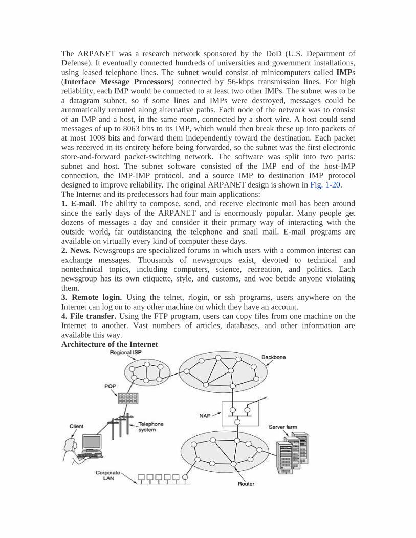
The ARPANET was a research network sponsored by the DoD (U.S. Department of
Defense). It eventually connected hundreds of universities and government installations,
using leased telephone lines. The subnet would consist of minicomputers called IMPs
(Interface Message Processors) connected by 56-kbps transmission lines. For high
reliability, each IMP would be connected to at least two other IMPs. The subnet was to be
a datagram subnet, so if some lines and IMPs were destroyed, messages could be
automatically rerouted along alternative paths. Each node of the network was to consist
of an IMP and a host, in the same room, connected by a short wire. A host could send
messages of up to 8063 bits to its IMP, which would then break these up into packets of
at most 1008 bits and forward them independently toward the destination. Each packet
was received in its entirety before being forwarded, so the subnet was the first electronic
store-and-forward packet-switching network. The software was split into two parts:
subnet and host. The subnet software consisted of the IMP end of the host-IMP
connection, the IMP-IMP protocol, and a source IMP to destination IMP protocol
designed to improve reliability. The original ARPANET design is shown in Fig. 1-20.
The Internet and its predecessors had four main applications:
1. E-mail. The ability to compose, send, and receive electronic mail has been around
since the early days of the ARPANET and is enormously popular. Many people get
dozens of messages a day and consider it their primary way of interacting with the
outside world, far outdistancing the telephone and snail mail. E-mail programs are
available on virtually every kind of computer these days.
2. News. Newsgroups are specialized forums in which users with a common interest can
exchange messages. Thousands of newsgroups exist, devoted to technical and
nontechnical topics, including computers, science, recreation, and politics. Each
newsgroup has its own etiquette, style, and customs, and woe betide anyone violating
them.
3. Remote login. Using the telnet, rlogin, or ssh programs, users anywhere on the
Internet can log on to any other machine on which they have an account.
4. File transfer. Using the FTP program, users can copy files from one machine on the
Internet to another. Vast numbers of articles, databases, and other information are
available this way.
Architecture of the Internet

Figure 1-21. Overview of the Internet. 1.5.2 Connection-Oriented Networks: X.25, Frame Relay, and ATM
X.25, which was the first public data connection oriented network. It was deployed in the
1970s at a time when telephone service was a monopoly everywhere and the telephone
company in each country expected there to be one data network per country—theirs. To
use X.25, a computer first established a connection to the remote computer, that is, placed
a telephone call. This connection was given a connection number to be used in data
transfer packets (because multiple connections could be open at the same time). Data
packets were very simple, consisting of a 3-byte header and up to 128 bytes of data. The
header consisted of a 12-bit connection number, a packet sequence number, an
acknowledgement number, and a few miscellaneous bits. X.25 networks operated for
about a decade with mixed success.
In the 1980s, the X.25 networks were largely replaced by a new kind of network called
frame relay. The essence of frame relay is that it is a connection-oriented network with
no error control and no flow control. Because it was connection-oriented, packets were
delivered in order (if they were delivered at all). The properties of in-order delivery, no
error control, and no flow control make frame relay akin to a wide area LAN. Its most
important application is interconnecting LANs at multiple company offices. Frame relay
enjoyed a modest success and is still in use in places today.
Asynchronous Transfer Mode
ATM (Asynchronous
Transfer Mode) is connection-oriented network. ATM was going to solve all the world's
networking and telecommunications problems by merging voice, data, cable television,
telex, telegraph, carrier pigeon, tin cans connected by strings, tom-toms, smoke signals,
and everything else into a single integrated system that could do everything for everyone.
ATM Virtual Circuits
Figure 1-22. A virtual circuit.
Since ATM networks are connection-oriented, sending data requires first sending a
packet to set up the connection. As the setup packet wends its way through the subnet, all
the routers on the path make an entry in their internal tables noting the existence of the
connection and reserving whatever resources are needed for it. Connections are often
called virtual circuits, in analogy with the physical circuits used within the telephone
system. Most ATM networks also support permanent virtual circuits, which are
permanent connections between two (distant) hosts. They are similar to leased lines in the
telephone world. Each connection, temporary or permanent, has a unique connection
identifier. Once a connection has been established, either side can begin transmitting data.
The basic idea behind ATM is to transmit all information in small, fixed-size packets
called cells. The cells are 53 bytes long, of which 5 bytes are header and 48 bytes are
payload, as shown in Fig. 1-23. Part of the header is the connection identifier, so the
sending and receiving hosts and all the intermediate routers can tell which cells belong to

which connections. This information allows each router to know how to route each
incoming cell. Cell routing is done in hardware, at high speed. In fact, the main argument
for having fixed-size cells is that it is easy to build hardware routers to handle short,
fixed-length cells. Variable-length IP packets have to be routed by software, which is a
slower process. Another plus of ATM is that the hardware can be set up to copy one
incoming cell to multiple output lines, a property that is required for handling a television
program that is being broadcast to many receivers. Finally, small cells do not block any
line for very long, which makes guaranteeing quality of service easier.
Figure 1-23. An ATM cell
1.5.3 Wireless LANs: 802.11
The proposed standard had to work in two modes:
1. In the presence of a base station.
2. In the absence of a base station.
In the former case, all communication was to go through the base station, called an
access point in 802.11 terminology. In the latter case, the computers would just send to
one another directly. This mode is now sometimes called ad hoc networking. A typical
example is two or more people sitting down together in a room not equipped with a
wireless LAN and having their computers just communicate directly. The two modes are
illustrated in Fig. 1-24.
Figure 1-24. (a) Wireless networking with a base station. (b) Ad hoc networking.
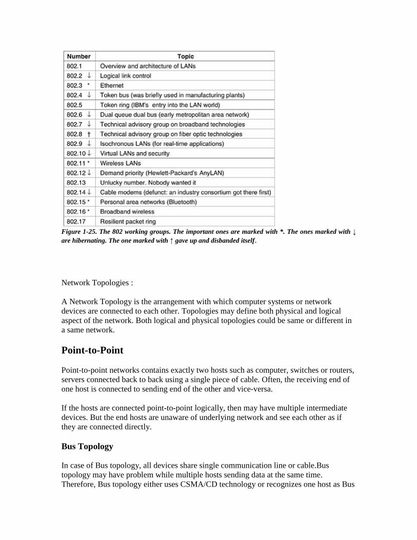
Figure 1-25. The 802 working groups. The important ones are marked with *. The ones marked with ↓
are hibernating. The one marked with ↑ gave up and disbanded itself.
Network Topologies :
A Network Topology is the arrangement with which computer systems or network
devices are connected to each other. Topologies may define both physical and logical
aspect of the network. Both logical and physical topologies could be same or different in
a same network.
Point-to-Point
Point-to-point networks contains exactly two hosts such as computer, switches or routers,
servers connected back to back using a single piece of cable. Often, the receiving end of
one host is connected to sending end of the other and vice-versa.
If the hosts are connected point-to-point logically, then may have multiple intermediate
devices. But the end hosts are unaware of underlying network and see each other as if
they are connected directly.
Bus Topology
In case of Bus topology, all devices share single communication line or cable.Bus
topology may have problem while multiple hosts sending data at the same time.
Therefore, Bus topology either uses CSMA/CD technology or recognizes one host as Bus

Master to solve the issue. It is one of the simple forms of networking where a failure of a
device does not affect the other devices. But failure of the shared communication line can
make all other devices stop functioning.
Both ends of the shared channel have line terminator. The data is sent in only one
direction and as soon as it reaches the extreme end, the terminator removes the data from
the line.
Star Topology
All hosts in Star topology are connected to a central device, known as hub device, using a
point-to-point connection. That is, there exists a point to point connection between hosts
and hub. The hub device can be any of the following:
Layer-1 device such as hub or repeater
Layer-2 device such as switch or bridge
Layer-3 device such as router or gateway
As in Bus topology, hub acts as single point of failure. If hub fails, connectivity of all
hosts to all other hosts fails. Every communication between hosts, takes place through
only the hub.Star topology is not expensive as to connect one more host, only one cable is
required and configuration is simple.
Ring Topology
In ring topology, each host machine connects to exactly two other machines, creating a
circular network structure. When one host tries to communicate or send message to a host
which is not adjacent to it, the data travels through all intermediate hosts. To connect one
more host in the existing structure, the administrator may need only one more extra cable.
Failure of any host results in failure of the whole ring.Thus, every connection in the ring
is a point of failure. There are methods which employ one more backup ring.
Mesh Topology
In this type of topology, a host is connected to one or multiple hosts.This topology has
hosts in point-to-point connection with every other host or may also have hosts which are
Hosts in Mesh topology also work as relay for other hosts which do not have direct point-
to-point links. Mesh technology comes into two types:
Full Mesh: All hosts have a point-to-point connection to every other host in the
network. Thus for every new host n(n-1)/2 connections are required. It provides
the most reliable network structure among all network topologies.

Partially Mesh: Not all hosts have point-to-point connection to every other host.
Hosts connect to each other in some arbitrarily fashion. This topology exists
where we need to provide reliability to some hosts out of all.
Tree Topology
Also known as Hierarchical Topology, this is the most common form of network
topology in use presently.This topology imitates as extended Star topology and inherits
properties of bus topology.
This topology divides the network in to multiple levels/layers of network. Mainly in
LANs, a network is bifurcated into three types of network devices. The lowermost is
access-layer where computers are attached. The middle layer is known as distribution
layer, which works as mediator between upper layer and lower layer. The highest layer is
known as core layer, and is central point of the network, i.e. root of the tree from which
all nodes fork.
All neighboring hosts have point-to-point connection between them.Similar to the Bus
topology, if the root goes down, then the entire network suffers even.though it is not the
single point of failure. Every connection serves as point of failure, failing of which
divides the network into unreachable segment.
Hybrid Topology
A network structure whose design contains more than one topology is said to be hybrid
topology. Hybrid topology inherits merits and demerits of all the incorporating
topologies.
The above picture represents an arbitrarily hybrid topology. The combining topologies
may contain attributes of Star, Ring, Bus, and Daisy-chain topologies. Most WANs are
connected by means of Dual-Ring topology and networks connected to them are mostly
Star topology networks. Internet is the best example of largest Hybrid topology