49953046-Final-Report-9794
59
INDUSTRIAL INTERNSHIP FINAL REPORT 1
-
Upload
fergot2010 -
Category
Documents
-
view
54 -
download
8
Transcript of 49953046-Final-Report-9794

INDUSTRIAL INTERNSHIP FINAL REPORT
1

INDUSTRIAL INTERNSHIP FINAL REPORT
2
EXECUTIVE SUMMARY
The Student Industrial Internship Program is conducted for 32 weeks and
compulsory for all student of UTP in order to graduate with Bachelor's Degree. The
students will undergo their industrial internship at a host company relevant to their
courses. The purpose of the industrial internship is to expose UTP students to the real
working environment and also develop skills which are necessary in the working life in
future.
The author was attached to Foxboro (M) Sdn Bhd, which is one of the Control
and Instrumentation company in Malaysia. Under supervision of Mr. Zulkefli Zakba,
Mr. Muharram and Mr. Aimee, the author has successfully completed a project relates
to the Distributed Control System (DCS) design. The author also able to get some
insight and practical application of theories learnt in UTP based on industrial practice.
This Industrial Internship Final Report summarizes all the relevant tasks and
projects that the author was involved during eight-month internship period at the host
company. The report consists of five main sections, the first section being the
Introduction which includes an introduction to the host company, the objectives of
internship program and the scope of the author's work during the internship period. The
second section covers the projects and activities done for the internship program. The
author's learning experiences will be well explained in the third section of the report. In
the fourth section, discussions and recommendations towards the Host Company and
UTP will be put across. The final section is a wrap up of the whole report consisting of
Conclusion, References and Appendices.

INDUSTRIAL INTERNSHIP FINAL REPORT
3
ACKNOWLEDGEMENT
First and foremost, I would like to convey my deepest appreciation and gratitude
to all supervisors and engineers at Foxboro which are Mr. Zulkefli, Mr. Aimee, Mr.
Muharram and Mr. Hafiz for their guidance, advice and discussions for the completion
and success of this internship. Without their support and encouragement, I would not be
able to have as much knowledge and input as I already gain from this internship.
Next, I want to thank all Foxboro staffs, apprentices and other interns for their
remarkable assist and sharing while I was there. With their help and support, I am able
to adopt with the new working environment and to cope with all the given task.
Other than that, I would also like to thank my UTP supervisor, Ms. Salina
Mohmad for travelling far away to attend industrial visit at my host company, for taking
the time to evaluate this report, and for her advices and suggestions regarding this
Industrial Internship Program.
Last but not least, I like to take this opportunity to express my appreciation to
my family, especially to my parent for giving me full support to complete this industrial
training. May ALLAH SWT bless them all and thank you so much for their support.

INDUSTRIAL INTERNSHIP FINAL REPORT
4
TABLE OF CONTENTS
VERIFICATION STATEMENT .................................................................................. 1
EXECUTIVE SUMMARY ........................................................................................... 2
ACKNOWLEDGEMENT .................................................................................... 3
TABLE OF CONTENT ....................................................................................... 4
LIST OF FIGURES AND TABLE ........................................................................ 5
CHAPTER I : INTRODUCTION
1.1 Description of Host Company .............................................................. 7
1.2 Objectives of Industrial Internship Program ........................................... 9
1.3 Scope of Works, Tasks and Project Undertaken ..................................... 10
CHAPTER II : PROJECTS AND ACTIVITIES
2.1 System Fundamental
2.1.1 Objectives ............................................................................. 11
2.1.2 Intelligent Automation (I/A) Series .......................................... 11
2.1.3 Process Control ...................................................................... 14
2.2 Software Induction
2.2.1 Introduction ........................................................................ 18
2.2.2 FoxView ............................................................................. 18
2.2.3 FoxDraw ............................................................................. 20
2.2.4 Integrated Control Configurator (ICC) .................................... 27
2.3 HIMA Upgrade Project
2.3.1 Introduction ..................................................................... 31
2.3.2 The Task .......................................................................... 31
2.3.3 Factory Acceptance Test (FAT) .......................................... 35

INDUSTRIAL INTERNSHIP FINAL REPORT
5
CHAPTER III : LESSON LEARNED AND EXPERIENCE GAINED
3.1 Technical Lessons
3.1.1 Foxboro I/A Series ............................................................... 41
3.2 Non-Technical Lessons
3.2.1 Communication Skills ........................................................... 41
3.2.2 Leadership and Management Skills ......................................... 42
3.2.3 Safety Training and Awareness ............................................... 42
3.3 Problems Faced ................................................................................... 43
CHAPTER IV : DISCUSSION AND RECOMMENDATIONS
4.1 Host Company .................................................................................... 44
4.2 UTP ................................................................................................... 45
CHAPTER V
CONCLUSION ....................................................................................... 46
REFERENCES ........................................................................................ 47
APPENDICES .......................................................................................... 48

INDUSTRIAL INTERNSHIP FINAL REPORT
6
LIST OF FIGURES AND TABLE
FIGURES
Figure 1.1 : Chart of Foxboro
Figure 2.1 : Components of control system
Figure 2.2 : Engineering diagram for Control Systems
Figure 2.3 : FoxView
Figure 2.4 : FoxDraw
Figure 2.5 : Sample FoxDraw Supplied Palettes
Figure 2.6 : I/A Series Symbol Palette Examples
Figure 2.7 : Configure Objects Dialog Box
Figure 2.8 : ECB16 Diagram
Figure 2.9 (a) : Mapping Table
Figure 2.9 (b) : Complete Database
Figure 2.10 : Loading Database to ICC
Figure 2.11 (a) : Configure Graphic
Figure 2.11 (b) : Edit Layout of Graphic
TABLE
Table 2.1 : ECBPG Parameters

INDUSTRIAL INTERNSHIP FINAL REPORT
7
CHAPTER I
INTRODUCTION
1.1: Description of Host Company
Foxboro Malaysia Sdn. Bhd. or Foxboro (M) Sdn. Bhd. is the result of a venture
between Invensys and a local associated company of Permodalan Usahawan Nasional
Berhad (PUNB) which is Progressive Impact Technology (PIT).
Foxboro (M) Sdn. Bhd. leading products and services fall into several inter-
related categories: Intelligent Automation (I/A) Series System for Distributed Control
System (DCS), SCADA and Remote Terminal Unit, Terminal Automation System and
Field Measurement and Instrumentation.
Foxboro (M) Sdn. Bhd., with its employees support Foxboro's entire range of
process control products including Design, Engineering, Fabrication, Integration,
Commissioning, Training and Maintenance. Foxboro (M) Sdn. Bhd. thrives in the areas
of engineering and customer service. Foxboro (M) Sdn. Bhd. operation has extensive
experience in handling design, engineering, procurement, site services and supports
associated with grass root projects, re-instrumentation, revamps and modernization
projects - all performed locally. All products and services are developed, delivered and
serviced under ISO 9001:2000 certified guidelines.

INDUSTRIAL INTERNSHIP FINAL REPORT
8
Foxboro (M) Sdn. Bhd. was established in Malaysia since 1977. Malaysia equity
participation since 1992:
Figure 1.1 : Chart of Foxboro
• Office Locations:
o Head Office: Bukit Jelutong, Shah Alam, Peninsular Malaysia.
o Branch Office 1: Bintulu, Sarawak, East Malaysia.
o Branch Office 2: Paka, Terengganu, Peninsular Malaysia.
• Local Agents (Field Instruments):
Peninsular & East Malaysia.
• Major Registration Status:
TNB License (PIT), MOF (PIT) and Petronas License.
Foxboro Malaysia is an ISO 9001 : 2000 Certified Organization

INDUSTRIAL INTERNSHIP FINAL REPORT
9
1.2: Objectives of Industrial Internship Program
The primary objective of the industrial internship is to expose UTP students to
the real working environment so that the student can relate theoretical knowledge
gained at the university with application in industry. Besides, the student will also be
able to develop work ethics and communication skills which can only be achieved
through actual working experience. At the end of the industrial internship program,
student will be able to:
i. To give opportunity to student to work with industrial practitioners
- Student will work and communicate with the practitioners from
different position such as managers, engineers, technicians, vendor and
etc.
ii. To expose students to potential employers
- Students will have an opportunity to create good acquaintances with the
individuals and organizations involved in the industry, which hopefully
will be useful for future purposes.
iii. To acquaint the UTP students with industry and its programs
- Students will aware on various industries related to their field of
studies. In the same time, it also enhances the student’s work ethics thru
the ethics practiced by industrial practitioners.
iv. To integrate theory with practice.
- Theory learned must be practice in a real life application. Thru
industrial internship program, student will have the opportunity to
correlate theory learned at university with the practical application in the
industry.

INDUSTRIAL INTERNSHIP FINAL REPORT
10
1.3: Scope of Work, Tasks and Projects Undertaken
1.3.1 System fundamental
• Attend briefing about Foxboro (M) system presented by En. Abdul Halim
i. Intelligent Automation (I/A) Series
ii. Introduction to Process Control
1.3.2 Software induction
• Study training manual provided about Intelligent Automation (I/A) series.
i. FoxView
ii. FoxDraw
• Attend training about I/A series conducted by engineering manager, Mr. Fuad.
i. Integrated Control Configurator (ICC)
1.3.3 Main Project
• Hima Upgrade Project
i. Creating the comparison table
ii. Do the mapping table
iii. Upload the database to the Application Workstation (AW)
iv. Configuring the graphic
v. Factory Acceptance Test (FAT)

INDUSTRIAL INTERNSHIP FINAL REPORT
11
CHAPTER II
PROJECTS AND ACTIVITIES
2.1: System Fundamental
2.1.1 Objectives
For the first 6 weeks of industrial training program, trainee had to undergo an
induction program which is a systematic training program for new engineers and staff
that acquire them to understand better the system used by Foxboro (M). Below are
training induction program objective:
• To provide basic technical knowledge necessary to enable engineers to
understand and apply on the features and benefit of Foxboro Automation
products, services and related offerings.
• Understand conceptual overview of the products
• Further enhance the depth of product knowledge necessary to build
yourself as a competent I/A System Engineer.
2.1.2 Intelligent Automation (I/A) Series
• Current offering by Foxboro (M)
i. Foxboro I/A Series System
ii. Foxboro A² Automation System
• Technology terms
i. Fault Tolerant
o 2 running module e.g. CP60

INDUSTRIAL INTERNSHIP FINAL REPORT
12
o Both modules running and process information at the same time with
identical image, once CP60 failed, the other will take over without
any delay
ii. Redundant
o 2 running modules e.g. LAN interface
o One module running and the other is on standby, once the running
module failed, the standby will take over with some delay over
transfer of image file
iii. Single
o 1 running module
o If module failed, no information from that module available to
DCS
• Hardware Component
i. Networks
o Nodebus – 10 Mbps
o Carrier Band LAN (interconnecting nodebus) – 5 Mbps
o Mixed – Nodebus & Ethernet
o Mesh networks – Ethernet
o Fieldbus
ii. Workstation
o Application workstation (AW) – AW functions as file/image
server for diskless station like Control Processor (CP) and
Gateway (GW). It also function as server for application like
integrated control configurator (ICC) and AIMHistorian package

INDUSTRIAL INTERNSHIP FINAL REPORT
13
(program file and data storage). AW can also be used as operator
workstation
o Model – AW50 series, AW51 series, P92, P93, P95, P79, P80,
P81 series
o Workstation processor (WP) – WP function as operator
workstation to monitor/control plant process/alarm thru custom
graphic display and alarm displays. Operator are able to change
setpoint of controller, acknowledge alarm and etc
o AW with control software – functions as operator workstation,
file server and also as control station to directly communicate
with FBMs, PLC etc depending on the control station software
loaded to it. Available in NT system and Solaris operating system
(Version prior to V8.0)
iii. Gateway (GW)
o GW functions as DCS interface to 3rd party subsystem e.g.
PLC. It processes the input/output signals from 3rd party
system via serial link communication. Normal protocol is
MODBUS RTU using RS232 (15 mtr), RS485 (~ 1.2 km)
o Current offering – GW30B, FBM23X (FDSI with
serial/Ethernet comm)
o Fault tolerant and simplex configuration
iv. Control Processor (CP)
o CP functions is to process the input/output signals from
Fieldbus Modules (FBM) and further process these signal
with required function such as PID controller, sequences
control, logic control, alarm, etc.

INDUSTRIAL INTERNSHIP FINAL REPORT
14
o Hardware series – CP10, CP30, CP40, CP60, FCP270,
ZCP270
v. Fieldbus Modules (FBM)
o Functions as an interface to input/output signals from the field
and send the information to CP for further processing such
analogue indication, analogue alarming, digital alarm indication
etc.
o Hardware series – FBM100 series, FBM200 series
vi. Others
o Communication Processor (COMM10) – functions as DCS
interface to printers
o Dual Nodebus Interface (DNBT) – functions as interface for
AW/WP to nodebus
o CBLAN Interface (CBLI)v – functions as interface for nodebus
to communicate to another nodebus
o Ethernet switches (100Mbps) with 1G uplinks
2.1.3 Process Control
A process control system is used to monitor data and control equipment on the
plant. Very small installations may use hydraulic or pneumatic control systems, but
larger plants with up to 30.000 signals to and from the process require a dedicated
distributed control system. The purpose of this system is to read values from a large
number of sensors, run programs to monitor the process and control valves switches etc.
to control the process. At the same time values, alarms, reports and other information
are presented to the operator and command inputs accepted.

INDUSTRIAL INTERNSHIP FINAL REPORT
15
Process control systems consists of following components:
Figure 2.1 : Components of control system
- Field instrumentation: sensors and switches that sense process conditions such as
temperature, pressure or flow. These are connected over single and multiple pair
electrical cables (hardwired) or communication bus systems called fieldbus.
- Control devices, such as Actuators for valves, electrical switchgear and drives or
indicators are also hardwired or connected over fieldbus.
- Controllers execute the control algorithms so that desired actions are taken. The
controllers will also generate events and alarms based on changes of state and alarm
conditions and prepare data for operators and information systems.

INDUSTRIAL INTERNSHIP FINAL REPORT
16
- A number of servers perform the data processing required for data presentation,
historical archiving, alarm processing and engineering changes.
- Clients such as operator stations and engineering stations are provided for human
interfaces.
- The communication can be laid out in many different configurations, often including
connections to remote facilities, remote operations support and similar.
Figure 2.2 : Engineering diagram for Control Systems
The main function of the control system is to make sure the production,
processing and utility systems operate efficiently within design constraints and alarm
limits. The control is typically specified in programs s a combination of logic and
control function blocks such as AND, ADD, PID. For a particular system, a library of
standard solutions such as Level Control Loop, Motor Control is defined. This means
that the system can be specified with combinations of typical loops, consisting of one or
more input devices, function blocks and output devices, rather than formal
programming.

INDUSTRIAL INTERNSHIP FINAL REPORT
17
The system is operated from the Central Control Room (CCR) with a
combination of graphical process displays, alarm lists, reports and historical data
curves. Desk screens are often used in combination with large wall screens as shown on
the right. With modern system the same information is available to remote locations
such as an onshore corporate operations support centre.
Field devices in most process areas must be protected not to act as ignition
sources for potential hydrocarbon leaks. Equipment is explosive hazard classified e.g. as
safe by pressurization (Ex.p), safe by explosive proof encapsulation (Ex.d) or
intrinsically safe (Ex.i). All areas are mapped into explosive hazard zones from Zone 0
(Inside vessels and pipes), Zone 1 (Risk of hydrocarbons), Zone 2 (Low risk of
hydrocarbons) and Safe Area.
Beyond the basic functionality the control system can be used for more
advanced control and optimization functions. Some examples are:
• Well control may include automatic startup and shutdown of a well and/or a set
of wells. Applications can include optimization and stabilization of artificial lift
such as Pump off control and Gas lift Optimization.
• Flow assurance serves to make sure that the flow from wells, in pipelines and
risers are stable and maximized under varying pressure, flow and temperatures.
Unstable flow can result in slug formation, hydrates etc.
• Optimization of various processes to increase capacity or reduce energy costs.
• Pipeline Management modeling, leak detection and pig tracking
• Support for Remote Operations, where facility data is available to company
specialists located at a central support center.
• Support for remote operation where the entire facility is unmanned or without
local operators full or part time, and is operated from a remote location.

INDUSTRIAL INTERNSHIP FINAL REPORT
18
2.2: Software Induction
2.2.1 Introduction
The I/A Series software is a sophisticated set of software that provides optimum
process control and management capability for a wide range of applications. It is easily
tailored to meet specific requirements and plant management needs and allows for the
distribution of functionality and computing power to a wide geographic area.
2.2.2 FoxView
FoxView is a window into the I/A Series system software, providing a user-
friendly interface to the total process. On either a 70 Series or 50 Series workstation,
user can interact with any or all of the real-time plant, field, and process data available
in the system. FoxView provides:
• Direct access to dynamic process displays
• Entry into user-configurable operating environments specific to each user - the
process engineer, process operator, and software engineer
• Execution of embedded real-time and historical trending
• Service and display of process alarms via the Alarm Manager
• An overview of the compounds and blocks in the control database and access to
block default detail displays via FoxSelect
• Access to other applications, such as:
- FoxDraw software for building and configuring dynamic user graphics
- System Management Displays for monitoring system equipment health
- Integrated Control Configurator for configuring the control database

INDUSTRIAL INTERNSHIP FINAL REPORT
19
- Historian for configuring the historization of data and system messages
- Access to FoxAlert Alarm Manager
- Access to the four most recently used displays.
Additionally, with FoxView user have:
• Flexibility in customizing environments to conform to the site requirements
• Rapid access to FoxView from other applications
• Screen print utility
• Window sizing options.
The multi-window capability of Solaris and Windows NT operating systems
allows user to monitor the information on a process control display as well as access
other applications without closing any window.
Figure 2.3 : FoxView

INDUSTRIAL INTERNSHIP FINAL REPORT
20
2.2.3 FoxDraw
FoxDraw is a display builder and configurator that allows user to create and
maintain dynamically updating process displays. Displays can represent the plant, a
process area or a detailed portion of the process.
User can draw basic objects using FoxDraw's toolbars, menu items and shortcut
keys. User assign graphic attributes such as color and line style to the objects, and then
configure them to reflect process variable changes or operator actions.
FoxDraw includes numerous palettes of objects such as operator buttons, pumps,
tanks, pipes, motors, valves and ISA symbols. User can also create own palettes for
storing complex objects and company-standard symbols. The Palette Browser helps
user navigate standard FoxDraw palettes as well as an extended library of I/A Series
Symbols palettes. Displays can include faceplates, trends and bitmapped images. User
can easily edit the displays to reflect changes in the process control scheme or to
maximize operating efficiency and security.
Using FoxDraw's built-in conversion utility, user can convert 50 Series displays
and markers and AutoCAD files to FoxDraw format.
Configuration information such as variable names and process limits (high/low
scale, for example) is retrieved through the FoxAPI server.
FoxDraw runs on Solaris and Windows NT platforms. It is also compatible with
Windows 95/98, so user can run it on a PC without I/A Series software. This means user
can build and maintain process displays on- or off-site, with optimum convenience and
flexibility.

INDUSTRIAL INTERNSHIP FINAL REPORT
21
Figure 2.4 : FoxDraw
2.2.3.1 Symbol Palettes
FoxDraw includes numerous palettes of pre-built objects such as pumps, tanks,
pipes, motors, valves, and ISA symbols. Standard libraries include vast selections of
simple and complex objects with which to build displays. User can copy an object from
a "copy" palette to a display and modify the object's primitive objects.

INDUSTRIAL INTERNSHIP FINAL REPORT
22
i. Standard Palettes
Palettes (see Figure 2.5) are collections of objects that user can select for use in
displays. Numerous useful display elements are available in FoxDraw supplied palettes,
and user can create your own palettes of frequently used objects. Foxboro supplied
palette objects include:
• ISA-recommended symbols
• Three-dimensional drawings of tanks, valves, pipes and utility equipment
• Buttons and switches
• Arrows
• Flow chart symbols
• Electronic symbols
• Workstations, consoles, and enclosures.

INDUSTRIAL INTERNSHIP FINAL REPORT
23
Figure 2.5 : Sample FoxDraw Supplied Palettes
ii. I/A Series Symbols Palettes
I/A Series Symbols provides over 1,200 configurable FoxDraw graphical objects
to help users build displays with greater flexibility and ease. It is an extended directory
of palettes designed to accompany I/A Series FoxDraw's existing palettes. Sample
displays built using the Symbols palette libraries are included with the CD-ROM.
Advantages of the Symbols FoxDraw palette library include:
• Every part of a graphic object can have its graphical attributes changed,
including fill color, pattern and level; edge color, style and thickness; and text
front, style and color.
• With the Palette Browser, user can install whatever palettes user want on the
hard drive.

INDUSTRIAL INTERNSHIP FINAL REPORT
24
• Every part of a graphic object can be configured for passive or operator
dynamics.
• Each graphic object is well labeled, for quick navigation, which allows the user
to easily find the piece or section of an object to be configured.
• Every graphical object has been optimized for best call up time during run-time.
• Engineering time is reduced to build new graphic objects.
Figure 2.6 : I/A Series Symbol Palette Examples

INDUSTRIAL INTERNSHIP FINAL REPORT
25
2.2.3.2 Configuration
There are two ways of configuring a display object. User can:
i. Choose the Dynamic Update tab to connect one of the object's attributes, such as
visibility or fill level, to a process variable or a file. With this type of
configuration, changes in an attribute are triggered dynamically by changes in
the process variable. No operator intervention is necessary.
ii. Choose the Operator Action tab to connect the entire object to an action, such as
opening a display, executing a command, or setting a value. An operator triggers
the action by selecting the object.
An individual object can have both types of connections, although it can have
only one operator action. Each object type (for example, rectangle, circle, text) has its
own set of dynamic attributes such as visibility, fill level and text color.
As shown in Figure 2.7, all configuration options are available from a single
dialog box that displays all selected objects. There is no need to reopen the dialog box
for each configuration task. A built-in filter provides a convenient way of selecting
desired object types.

INDUSTRIAL INTERNSHIP FINAL REPORT
26
Figure 2.7 : Configure Objects Dialog Box
User can assign unique names to the objects that has been created and configure
in FoxDraw. While the names are optional, they are useful for distinguishing among
several objects of the same type in a single display. User configure an object's dynamic
attributes to the value of a variable (process variable or shared variable) which then
controls the object's behavior.
User can specify an object's static presentation (as specified by its graphic
attributes). Typically, these attributes determine an object's fill and edge. A text object's
specifications include font style, color, and direction. A display object can reflect the
current value of a process variable. The appearance of a display object can be animated,
based on the value of one or more process variables. User configure animation by
specifying an object's dynamic attribute, choosing a conversion method, and creating a
table of expected inputs and desired outputs.
FoxDraw allows user to assign an operator action to a display object, creating an
interactive connection between the display object and the operator. This capability
permits an operator to trigger an event by performing an action or record data.

INDUSTRIAL INTERNSHIP FINAL REPORT
27
2.2.4 Integrated Control Configurator (ICC)
2.2.4.1 Integrator Database Configuration
When configuring the Integrator, it is recommended that user verify proper
communication with the PLCs prior to configuring the compounds or blocks, as
follows:
i. Configure the ECBP and ECB16’s.
ii. Verify proper operation of ECBP (goes on-line, or white, automatically after an
Integrator reload providing all initialization checks are successful).
iii. Verify proper operation of ECB16’s (MOD PC). These must be initially turned
on-line by selecting GO ON-LINE from the Equipment Change Display
(Peripheral Change Option).
Once all ECBs are on-line and communication has been established, compound and
block configuration can begin.
Please observe the following rules:
i. Only one MDSCAN is allowed per compound.
ii. The MDSCAN block must be the first block entered in a compound, to ensure
processing of current data.
iii. Control and I/O blocks operating on PLC data retrieved by a MDSCAN block
must be resident in the same compound as that MDSCAN block.
iv. All I/O blocks in a compound must be configured to execute in a BPC in which
the associated MDSCAN executes. Failure to comply causes the I/O block to
process data values of 0.

INDUSTRIAL INTERNSHIP FINAL REPORT
28
v. All blocks that perform I/O must be in the same compound as the MDSCAN
block, must be the same phase as the MDSCAN block and cannot run at a faster
frequency than the MDSCAN block.
vi. Within a compound, block periods can be equal to, or a multiple of, the
MDSCAN block PERIOD. I/O blocks should not be configured to execute at a
faster frequency than the associated MDSCAN block.
vii. A MDSCAN block may request up to 256 bytes of data (2000 register for coil or
contact values; 125 registers for analog values).
viii. Multiple compounds may be configured to run in a single phase, but the I/O load
should be kept under 75% as shown by the Station Block display. This equates
to reading approximately 900 bytes per second at 9600 baud or 1800 bytes per
second at 19,200 baud. Additionally, the number of block equivalents executing
per second should not exceed 300. If either limit is exceeded, BPC overruns may
occur.
Figure 2.8 : ECB16 Diagram

INDUSTRIAL INTERNSHIP FINAL REPORT
29
2.2.4.2 Compound Configuration
An Integrator compound can contain one and only one MDSCAN block, and
this block must be the first block (top of the list) in the list of blocks in a compound.
When configuring the compound, the recommended settings for period and phase are 1
and 0, respectively.
Compounds in the Integrator may exist without a MDSCAN block; however,
any block which performs I/O to the PC must be in a compound which contains an
associated MDSCAN block (which addresses the PC memory location of the I/O block)
2.2.4.3 ECBPG Block Configurations
Basic ECBPG Parameters:
Table 2.1 : ECBPG Parameters
NRBUS This parameter defines the number of active ports: 1 = 1 port 2 = 2 ports.
Set NRBUS=1 for non fault tolerant gateway.
BUSTYP The value configured for BUSTYP is the number of retries to make in case of communications failures, before failing a device.
The default value of R for this parameter prevents the premature initialization of the integrator's hardware interface to the communications channel(s) to the field devices. When the ECBP or ECBPG parameters have been configured to their desired values, and the R is changed to any other value, the communications interface is initialized in accordance with the other configured parameters.

INDUSTRIAL INTERNSHIP FINAL REPORT
30
PIOWDT PIO Watch Dog Timer is a nonconnectable, nonsettable integer input that determines the value, in seconds, of each FBMs communications watch dog timer.
Each FBM’s BSDLAY parameter is based on the value of PIOWDT. PIOWDT can be only be changed by the FBM Configure function of the Integrated Control Configurator.
BAUD RS-232-C serial communications baud rate selection: 3 = 19200 4 = 9600 5 = 4800 6 = 2400 7 = 1200 8 = 600 9 = 300 3 is not available for the gateway integrator.
DATBIT RS-232-C serial communications number of data bits: 7 or 8.
PARITY RS-232 serial communications parity selection: 0 = no parity 1 = odd parity 2 = even parity
STPBIT RS-232-C serial communications number of stop bits: 1 or 2.
The communication settings above should matched to the PLC devices for
communication to be establish properly.

INDUSTRIAL INTERNSHIP FINAL REPORT
31
2.3: HIMA Upgrade Project
2.3.1 Introduction
HIMA is the first port of call for many companies throughout the world when it
comes to safety-related automation solutions. The secret of success is that HIMA focus
uncompromisingly on the field of safety. That is because focus leads to absolute
expertise and increases experience - and that in turn means better solutions for process,
machine and building safety. It is one of the leading PLC company in safety and
shutdown system.
HIMA Upgrade Project is one of the project owns by Malaysia Liquefied
Natural Gas (MLNG) as the client. The purpose of doing this upgrade is because
HIMA, as the third party PLC for shutdown and safety system, has upgraded their
system by dividing the I/O into two gateway and some new point has been added to
their system. So, Foxboro as the Distributed Control System (DCS) side, have to follow
the new system from HIMA and also have to upgrade the system accordingly. This is
because the graphic for the system and process of the plant is showed at DCS side.
2.3.2 The Task
2.3.2.1 Build The Database For The System
For this project, the upgrade consists total of 19 gateways to be upgraded
including Fire Fighting and Gas Detection System. So, there are 19 different database to
be build or edit depends on the I/O list and mapping table. Mapping table shows the
analogue and digital point that DCS connected to HIMA PLC side. Usually use excel to
build. It is the important document for F.A.T.

INDUSTRIAL INTERNSHIP FINAL REPORT
32
Figure 2.9 (a) : Mapping Table
Next task after completing the mapping table is starting to build the real
database. From the mapping table, we know where to locate the block in the database. If
the block does not exist in the database, new block is created.
Figure 2.9 (b) : Complete Database

INDUSTRIAL INTERNSHIP FINAL REPORT
33
2.3.2.2 Load The Database To Application Workstation (AW)
For this purpose, the database in CSV file been converted into ICC file before
uploading it to the AW. Check the database in ICC and make sure all the blocks have
been uploaded. Configure the parameters of the block using ICC so that the block is
function. For this project, the changes of the database mostly on the naming of the
compounds, but the blocks name remain same as existing name.
Figure 2.10 : Loading Database to ICC
2.3.2.3 Configure and Edit The Graphic
For this upgrade, the graphic needs to be reconfigured because of the change of
the compound name in the database. Use Display Configurator to change the
configuration of the graphic. Display Builder can be used to edit the graphic.

INDUSTRIAL INTERNSHIP FINAL REPORT
34
Figure 2.11 (a) : Configure Graphic
Figure 2.11 (b) : Edit Layout of Graphic

INDUSTRIAL INTERNSHIP FINAL REPORT
35
2.3.3 Factory Acceptance Test (FAT)
2.3.3.1 Introduction
The intent of FAT is to provide an integration testing procedure for the I/A
Series DCS System with HIMA PLC System. It describes Integration Test management
aspects, participation, problem classifications and resolutions, acceptance and
overviews of the tests.
This FAT shall govern the scope and test methods to be performed during the
whole duration of the Integration Test. Deviations from the said documented procedures
shall not be allowed unless otherwise agreed between Foxboro, HIMA and MLNG. The
objectives of the Integration Test are:
• To demonstrate that the Foxboro DCS system communicates correctly with the
HIMA, that the software configuration of the communication modules has been
completed correctly and that total system performance meets MLNG functional
specification and technical directions which have been agreed upon throughout
the project execution phase, as documented in relevant referenced
correspondence and approved drawings.
The objective of testing of interfaces to the I/A Series verify and establish that:
i. I/A and the HIMA can communicate and exchange read/write data.
ii. Address mapping between I/A and the HIMA is consistent.
iii. Control database functions configured within the I/A System are correct.
iv. Data from HIMA are properly displayed on I/A displays.
v. There are fall back and recovery schemes in place that lead to acceptable
situations in the event of partial or total loss of communication.

INDUSTRIAL INTERNSHIP FINAL REPORT
36
In order to achieve above objectives:
i. HIMA PLC will be tested for communication compatibility with I/A DCS
system.
ii. Complete I/O testing for the HIMA interface shall be checked for address
mapping by reference to HIMA and Foxboro supplied documents.
iii. I/A resident control/display functions shall be checked for the gateway blocks.
iv. Special communication failure schemes shall be checked.
v. Error messages generated by HIMA (if any) that are part of the interfaces shall
be checked.
Actual interface devices shall be integrated to I/A system, forced to simulate conditions
of data change from PLCs. Verification of data transfer and configuration in DCS
involves viewing the data status in detail blocks as well as user graphic displays,
checking alarm reports and checking safety an functions. In order to assist in having the
integration test run in an organized, systematic manner, the following information is
included:
a) Test procedures
b) Log forms (System activity log, problem log, etc.)
c) Inventory and test forms
d) Acceptance/waiver forms

INDUSTRIAL INTERNSHIP FINAL REPORT
37
2.3.3.2 Integration Test Methodology
2.3.3.2.1 Integration Test Management
The Foxboro DCS Lead Engineer shall be responsible ensuring personnel and
facilities are adequate for the performance of the integrated test. All test activities shall
be managed by the DCS Lead Engineer/Project Engineer responsible taking the system
to the jobsite.
2.3.3.2.2 Participation
The proposed integration test program is a joint effort between Foxboro and
HIMA, which is witnessed by MLNG. Separate physical test teams are normally
assigned for each test section to prevent confusion due to system complexity. The
general anatomy of a test team is as follows:
a) MLNG Representative.
b) HIMA PLC Representative.
c) Foxboro implementation engineer.
For the testing, MLNG representative witnesses the test to be performed with the
Foxboro DCS implementation engineer being responsible for demonstration of system
function. Foxboro/MLNG representative shall be responsible for logging problems in
the problem log.
2.3.2.2.3 Software Control
Software modifications shall only be performed by equipment owners. For DCS
software, modification to control and I/O configuration may only be made by Foxboro
Engineer who shall take equipment to the jobsite. DCS software version numbers shall
be updated in the DCS system log when they are revised.

INDUSTRIAL INTERNSHIP FINAL REPORT
38
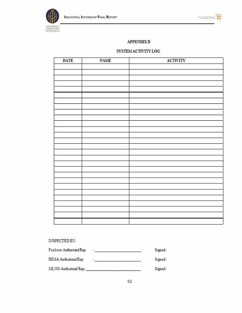
2.3.3.2.4 System Activity
Foxboro I/A Series system activity shall be monitored and recorded once the
system is powered up until acceptance. All kind of abnormal activities shall be recorded
in this System Activity Log. This is to check the hardware failures during testing. Please
refer Appendix D.
2.3.3.2.5 Problem Resolution
When product deficiencies (non-conformance to specifications) are identified
during the course of the tests, they will be recorded and Foxboro will initiate corrective
action. However, the test will continue, even though the deficiency may not have been
corrected (in accordance with the problem classifications, see section below). It is
desirable to initially run the demonstration from beginning to end (when possible), and
thereby, define all deficiencies that require additional work. All deficiencies will then
be corrected and appropriate tests re-run to demonstrate that the deficiencies have been
corrected. Where possible, Foxboro shall endeavor to rectify deficiencies on a daily
basis and demonstrate corrections the next day to prevent an accumulation of
unresolved issues.
Five major classes of problems are identifiable which may occur during the test period:
CLASS 1 Testing cannot continue until the problem is resolved (e.g., processor
failure and system is not functional for further testing without repair).
CLASS 2 Continued testing is not obstructed, but the system cannot be accepted
for shipment until the problem is resolved (e.g., software bug disabling a
process critical function i.e. system implementation configuration errors.
CLASS 3 Shipment need not be delayed, but the modifications/revisions must be
implemented prior to customer field acceptance.

INDUSTRIAL INTERNSHIP FINAL REPORT
39
CLASS 4 Foxboro, HIMA and MLNG agreed scope extensions that extend the
scope of the system from that defined by Foxboro, HIMA and MLNG.
Agreed scope extensions will require review for schedule impact and
cost prior to formal implementation schedule.
CLASS 5 Software bugs which require non standard techniques (or work around)
to utilize a needed function. All system faults (e.g. software bugs, etc)
shall be corrected prior to shipment.
When a problem occurs, Foxboro, HIMA and MLNG will prepare a description
of the problem on a PROBLEM LOG form. This form will be directed to the Foxboro
Service Manager or his designated representative for this particular area of the test.
Foxboro will then respond with a classification of the problem that is mutually
agreeable to both parties. Next, Foxboro will then submit to HIMA a schedule for
resolution of the problem. Finally, Foxboro will proceed with the resolution in
accordance with the submitted schedule and the problem classification, as follows:
CLASS 1 Foxboro project personnel will work to correct the problem. The test
section that was being executed at the time the problem occurred will be
repeated as appropriate, depending upon the fault.
CLASS 2 The problem will be recorded on a PROBLEM LOG form, with a
schedule for resolution. At the time the problem is corrected by Foxboro
project personnel, the test section that was being executed at the time the
problem occurred will be repeated from the beginning.
CLASS 3 The modification/revisions will be recorded on a PROBLEM LOG form,
with a schedule for resolution.
CLASS 4 Foxboro will promptly prepare a schedule proposal and cost estimate for
the desired application

INDUSTRIAL INTERNSHIP FINAL REPORT
40
CLASS 5 Software bugs which require non-standard techniques [or work-around]
to utilize a needed function shall be corrected before shipment. At the
time the problem is corrected, a suitable test for it will be developed.
The test will be reviewed and agreed by Foxboro, HIMA and MLNG.
2.3.3.2.6 Reporting Test Result
Foxboro shall be responsible for maintaining records of the test result entered on
forms specifically designed for the test. The SIT test results along shall form the basis
for signing the Inspection Release Certificate required before the system can be
accepted. When test results are negative, the problem reporting procedures shall be
followed.

INDUSTRIAL INTERNSHIP FINAL REPORT
41
CHAPTER III
LESSON LEARNED AND EXPERIENCE GAINED
After going through 32 weeks of training in Services Department at Foxboro
(M), I have gained a lot of experiences and learned so many things related to employee
disciplines as well as an engineer. Apart from applying theoretical knowledge to the
industry based practice, the author also gained various experiences related to DCS
engineer working life. Moreover, the nature of Foxboro in treating the trainee like the
real engineer allows the author to grab as much knowledge as possible from the project
masters, engineers, apprentices, trainees and other interns. Lastly, the author was able to
improve his soft skills through observation and experience with other fellow workers.
3.1: Technical Lessons
3.1.1 Foxboro I/A Series
Throughout the internship program, the author was exposed to the software that
Foxboro use to design the DCS system for the plant called I/A Series. Using this
software, the author can design the graphic layout for certain plant and configure the
graphic as well. FoxView and FoxDraw are the common utilities that have been used by
the author during his internship period.
3.2: Non-Technical Lessons
3.2.1 Communication Skills
The past eight months internship was the author's first experience of the working
life. He had to make full use of his soft skills in order to successfully complete the given
tasks. Good communication skills are a necessity as most of the tasks assigned to the
author could not be done by the author alone. Discussions and consultations with other
engineers are required to understand the related topic to the task. So, it is vital to the

INDUSTRIAL INTERNSHIP FINAL REPORT
42
author to communicate effectively or to convey the messages and questions correctly,
so that problem faced can be solved easily. Besides, the author was also required to
present the project output to the supervisor for grading purpose which in the same time
helping to improve the author's communication and presentation skill.
3.2.2 Leadership And Management Skills
Leadership and management are most important skills that must have in an
employee to become successful person in his/her career. During 32 weeks of training at
Foxboro (M) the author have gain many experience that build his leadership and
management skill. On the second week of the training, the author was asked to make a
planning schedule to complete the task given to him. This schedule develop his skill on
manage time to complete the task on time without any delay.
Working with a leader Mr. Zulkefli, as his supervisor, was a great experience
where the author can observe how a leader work and manage the department jobs. The
way he works little bit influences how the author performs in his work. His skill on lead
a group encourage the author to work hard and become a good leader in the future.
3.2.3 Safety Training And Awareness
At Foxboro (M), the author have undergone safety briefing about the importance
of safety environmental in order to give awareness towards the danger exposed in the
plant and know the procedures for handling portable extinguisher beside acknowledge
about the acts available related to health and safety. The content of the course include:
• Occupational Safety and Health Act (OSHA)
• Emergency fire extinguishers such as fire fighting hose and fire fighting hose.
• Personal Protective Equipment (PPE)
• Emergency help due to exposure.

INDUSTRIAL INTERNSHIP FINAL REPORT
43
3.3: Problems Faced
Every work has its own challenges and problems. As a trainee, the first
challenge that the author faced is to adapt with the working environment practiced at the
host company. However, after several weeks working, the author was able to work at
ease at both site office and staging room as the workers are very friendly and extremely
helpful in resolving any problems occurred during the training period.
In the process of finishing the projects given by the supervisor, sometimes the
author have to find information from different persons. The author have takes this as
challenges in dealing with people from different level. Sometimes it is very difficult to
find answers to solve the tasks given because of the lost of data and lack of information
on the tasks. When this happened, the author have to search for the answers from the
engineers. Dealing with experienced people from different levels was a challenge where
the communication skill is very important.
Doing work that different from what the author learned at UTP also another
problem faced by him during his internship training at Foxboro (M). Task that given
need him to learn new things to finish it up. The author have to learn I/A series software
that used by Foxboro (M) by himself. Although there are many problems and challenges
faced during internship, the author have successfully encountered them with the help
from family, friends and supervisors.

INDUSTRIAL INTERNSHIP FINAL REPORT
44
CHAPTER IV
DISCUSSION AND RECOMMENDATIONS
The industrial internship programmed offered by UTP, which is prior to the
completion of our studies in UTP carries fourteen credit hours and lasts for thirty-two
weeks. This internship turns out to be an excellent experience indeed where the
undergraduate student of UTP managed to undergo practical work in the industry and
not only learn the theoretical knowledge from class. The Industrial Internship Program
(IIP) guidelines book provided to both students and plant supervisors is really help in
ensuring the success of the program. Nevertheless there are some rooms for the program
improvement that need to be discussed here.
4.1: Host Company (Foxboro)
4.1.1 Group
A trainee should be assign to a group of engineers or work in a group with other
engineers. This is important so that trainee can learn from the other engineers and also
can become reference for the trainee when they face a problem. In the process of
learning it is proved that learning in a group is better than learning alone. So, I strictly
recommend Foxboro(M) to put trainee in a group of engineers for their learning process
as well as doing their work as a trainee at Foxboro (M).
4.1.2 Schedule of training
Foxboro (M) should prepared schedule of training for trainees before they arrive
to the host company. The schedule should include what project will be involved and
training will be attended by the trainees during their 32 weeks of training. This is to
make sure all trainees that come to Foxboro (M) doing what suppose they do and not
just wasting time surfing internet or walking around the company. Good schedule of
training will give benefit to both sides. Company will get extra man power while trainee
get new knowledge and experience that cannot be achieve at university.

INDUSTRIAL INTERNSHIP FINAL REPORT
45
4.2: UTP
4.2.1 Reduce weekly report
The Industrial Internship Committee (ITC) should review on the significant
number of report and written works that have to be produce by the student during the
Industrial Internship Program (IIP). At the current situation, students have to write a
report on the highlights of their activities on weekly basis instead of the final report at
the end of the training. Most of the supervisors and the students found that, the
requirement is so burdening. Students have to carry out their routine works at the office,
complete the assignments given by the supervisor and the same time they prepare the
weekly report for the IIC. As consequences, UTP trainees are tends to spend most of
their time sit in front the computer or looks for the relevant material in the library to
deal with their report. It will bring no good for the efficiency of the IIP. It also
burdening the supervisors to read and give mark to the report since they are already
busy with their routine work as an engineer.
4.2.2 Marking scheme standardization
The weekly evaluation carried a big portion which about 30 percent of the total
marks of the IIP. For the time being there is no proper marking scheme standardization
on that based on their experience and own justification. Oral presentation marking
should be done by UTP supervisor only except the content. It will be fair for all trainees
as for experienced engineers who are the IIP supervisor, they will more flexible in
evaluating the students compared to the new engineers who set for a higher
requirements and expectation. A proper marking scheme has to be established and a
better supervision by the IIC should be carried out. IIC should looks in depth on this
matter.

INDUSTRIAL INTERNSHIP FINAL REPORT
46
CHAPTER V
CONCLUSION
After 32 weeks undergoing Industrial Internship Program at Foxboro (M), a lot
of interesting things can be concluded by the end of my industrial training. Being
exposed to the real working environment, especially in electrical engineering field has
given me many useful knowledge and practical to learn. Involved in project and done
tasks those given to me really challenge me to become a real engineer although I am
still a student. Being trusted by supervisor and engineers in Foxboro (M) to handle and
involved with their projects give me a feel that big responsibilities lay on me. In
conclusion, this industrial training had achieved it objective to expose Universiti
Teknologi Petronas (UTP) students to the real working environment so that they can
relate theoretical knowledge with application in industry. At Foxboro (M), even though
not all tasks that given to me completely practiced my knowledge as electrical and
electronic engineering student at UTP, there still have relation that I can relate and used.
This industrial internship also develop my skills in safety practices, work ethics,
communication, management, and many more as state on the objective of industrial
training program.

INDUSTRIAL INTERNSHIP FINAL REPORT
47
REFERENCES
• www.foxboro.com.ny
• www.hima.com
• Training module of Introduction To Configuration – I/A Series software
(Module 2)
• Training module of Introduction To Configuration – FoxDraw (Module 4)
• Manual of I/A Series V8.11
• FoxDoc 8.3

INDUSTRIAL INTERNSHIP FINAL REPORT
48
APPENDICES

INDUSTRIAL INTERNSHIP FINAL REPORT
49

INDUSTRIAL INTERNSHIP FINAL REPORT
50

INDUSTRIAL INTERNSHIP FINAL REPORT
51
INDUSTRIAL INTERNSHIP FINAL REPORT
52

INDUSTRIAL INTERNSHIP FINAL REPORT
53

INDUSTRIAL INTERNSHIP FINAL REPORT
54

INDUSTRIAL INTERNSHIP FINAL REPORT
55

INDUSTRIAL INTERNSHIP FINAL REPORT
56

INDUSTRIAL INTERNSHIP FINAL REPORT
57

INDUSTRIAL INTERNSHIP FINAL REPORT
58

INDUSTRIAL INTERNSHIP FINAL REPORT
59


![[DRAFT, PRE-FINAL OR FINAL] REPORT - OECD](https://static.fdocuments.net/doc/165x107/5ec770f8c7c9f9670a3f7375/-draft-pre-final-or-final-report-.jpg)