
490NBX – ASCII to PLC Gateway · 490NBX – ASCII to PLC Gateway Product User Guide Software...
43
490NBX – ASCII to PLC Gateway Product User Guide Software Build Date: July 18 th , 2016 Version 3.1.1 Platform: NNA1 Real Time Automation, Inc. 1 1-800-249-1612
Transcript of 490NBX – ASCII to PLC Gateway · 490NBX – ASCII to PLC Gateway Product User Guide Software...

490NBX – ASCII to PLC Gateway Product User Guide
Software Build Date: July 18th, 2016
Version 3.1.1 Platform: NNA1
Real Time Automation, Inc. 1 1-800-249-1612

Trademarks
CompactLogix, ControlLogix, & PLC-5 are registered trademarks of Rockwell Automation, Inc. EtherNet/IP is a trademark of the ODVA. MicroLogix, RSLogix 500, and SLC are trademarks of Rockwell Automation, Inc. Microsoft, Windows, and Internet Explorer are registered trademarks of Microsoft Corporation. BACnet® is a registered trademark of American Society of Heating, Refrigerating and Air-Conditioning Engineers (ASHRAE). All other trademarks and registered trademarks are the property of their holders.
Limited Warranty
Real Time Automation, Inc. warrants that this product is free from defects and functions properly.
EXCEPT AS SPECIFICALLY SET FORTH ABOVE, REAL TIME AUTOMATION, INC. DISCLAIMS ALL OTHER WARRANTIES, BOTH EXPRESSED AND IMPLIED, INCLUDING BUT NOT LIMITED TO IMPLIED WARRANTIES OF MERCHANTABILITY OR FITNESS FOR A PARTICULAR APPLICATION. THIS LIMITED WARRANTY GIVES YOU SPECIFIC LEGAL RIGHTS. YOU MAY ALSO HAVE OTHER RIGHTS, WHICH VARY FROM STATE TO STATE.
The examples and diagrams in this manual are included solely for illustrative purposes. Because of the many variables and requirements associated with any particular application, Real Time Automation, Inc. cannot assume responsibility or liability for actual use based on the examples and diagrams. Except as specifically set forth above, Real Time Automation and its distributors and dealers will in no event be liable for any damages whatsoever, either direct or indirect, including but not limited to loss of business profits, income, or use of data. Some states do not allow exclusion or limitation of incidental or consequential damages; therefore, the limitations set forth in this agreement may not apply to you.
No patent liability is assumed by Real Time Automation with respect to use of information, circuits, equipment, or software described in this manual.
Government End-Users
If this software is acquired by or on behalf of a unit or agency of the United States Government, this provision applies: The software (a) was developed at private expense, is existing computer software, and was not developed with government funds; (b) is a trade secret of Real Time Automation, Inc. for all purposes of the Freedom of Information Act; (c) is “restricted computer software” submitted with restricted rights in accordance with subparagraphs (a) through (d) of the Commercial “Computer Software-Restricted Rights” clause at 52.227-19 and its successors; (d) in all respects is proprietary data belonging solely to Real Time Automation, Inc.; (e) is unpublished and all rights are reserved under copyright laws of the United States. For units of the Department of Defense (DoD), this software is licensed only with “Restricted Rights”: as that term is defined in the DoD Supplement of the Federal Acquisition Regulation 52.227-7013 (c) (1) (ii), rights in Technical Data and Computer Software and its successors, and: Use, duplication, or disclosures is subject to restrictions as set forth in subdivision (c) (1) (ii) of the Rights in Technical Data and Computer Software clause at 52.227-7013. If this software was acquired under GSA schedule, the U.S. Government has agreed to refrain from changing or removing any insignia or lettering from the Software or documentation that is provided or from producing copies of the manual or media. Real Time Automation, Inc.
© 2016 Real Time Automation, Inc. All rights reserved.
Real Time Automation, Inc. 2 1-800-249-1612

Overview ....................................................................................................................................................... 5
Hardware ...................................................................................................................................................... 6
Powering the Gateway .............................................................................................................................. 6
Accessing the Main Page............................................................................................................................... 7
Error: Main Page Does Not Launch ........................................................................................................... 8
Committing Changes to the Settings ............................................................................................................ 9
Main Page ................................................................................................................................................... 10
Device Configuration ................................................................................................................................... 11
PLC Configuration........................................................................................................................................ 12
TCP/IP Communication Setup ..................................................................................................................... 14
Is my device a Server or Client? .............................................................................................................. 14
If the Gateway is a Client Connecting to a Server Device ....................................................................... 14
If a Client Device is Connecting to the Gateway Acting as a Server ....................................................... 15
Setting up ASCII to PLC Communication ..................................................................................................... 16
Define PLC Tag / File................................................................................................................................ 16
Define ASCII Message Termination ......................................................................................................... 17
Message Queue....................................................................................................................................... 18
Data Conversion ...................................................................................................................................... 18
Setting up PLC to ASCII Communication ..................................................................................................... 19
Define PLC Tag / File................................................................................................................................ 19
Add Delimiters to ASCII Message ............................................................................................................ 20
Data Conversion ...................................................................................................................................... 20
Diagnostics and Troubleshooting................................................................................................................ 21
PLC Status ................................................................................................................................................ 21
Port & Direction Selection ...................................................................................................................... 21
TCP/IP Information .................................................................................................................................. 21
Diagnostics and Troubleshooting – ASCII to PLC ........................................................................................ 22
Diagnostic Counters ................................................................................................................................ 23
Diagnostics and Troubleshooting – PLC to ASCII ........................................................................................ 24
Diagnostic Counters ................................................................................................................................ 25
Diagnostics and Troubleshooting – LEDs .................................................................................................... 26
Diagnostics – Main Page ............................................................................................................................. 27
PLC Status ................................................................................................................................................ 27
ASCII Status ............................................................................................................................................. 27
Real Time Automation, Inc. 3 1-800-249-1612

Device Status ........................................................................................................................................... 28
Save/Load the Configuration ...................................................................................................................... 29
Export Configuration ............................................................................................................................... 29
Import Configuration .............................................................................................................................. 29
Utilities ........................................................................................................................................................ 30
Revision Listing ........................................................................................................................................ 30
Diagnostics Logging ................................................................................................................................. 30
Security Configuration ............................................................................................................................ 31
Security - Log In ....................................................................................................................................... 31
Upgrade Firmware .................................................................................................................................. 32
Reset Gateway ........................................................................................................................................ 32
Intelligent Reset Button .............................................................................................................................. 33
Save and Replace Configuration using SD Card .......................................................................................... 34
Data Transfer To/From SD Card .............................................................................................................. 34
Using IP Setup with SD Card .................................................................................................................... 34
Appendix A: Error Definitions ..................................................................................................................... 35
Appendix B: I/O Messaging - Configuration (Rev 7.03 or Later) ................................................................. 39
Input / Output Assembly Byte Breakdown ............................................................................................. 39
Input / Output Assembly Handshaking Breakdown ................................................................................ 40
ASCII to PLC ......................................................................................................................................... 40
PLC to ASCII ......................................................................................................................................... 40
Input / Output Assembly Diagnostics Breakdown .................................................................................. 41
I/O Adapter Comm LED 2 ........................................................................................................................ 41
Appendix C: Create User Defined Tag in RSLogix 5000 ............................................................................... 42
Appendix D: How to Access Program Scope Tags in RSLogix5000 .............................................................. 43
Real Time Automation, Inc. 4 1-800-249-1612

Overview The 490NBX gateway seamlessly connects up to 10 Ethernet TCP/IP devices to a ControlLogix, CompactLogix, FlexLogix, MicroLogix, PLC5E, SLC, or other legacy PLC featuring a NetENI module.
Tools and documents available online: http://www.rtaautomation.com/product/435-nbx-support/
If at any time you need further assistance do not hesitate to call Real Time Automation support.
Support Hours are Monday-Friday 8am-5pm CST
Toll free: 800-249-1612 Email: [email protected]
Real Time Automation, Inc. 5 1-800-249-1612

Hardware
Powering the Gateway • An 8-24 VDC power source to the gateway, Red Wire = (+) Black Wire = (-).
a. The unit draws 175mA @ 12V.
Real Time Automation, Inc. 6 1-800-249-1612

Accessing the Main Page The following steps will help you access the browser based configuration of the 490NBX. By default, DHCP is enabled. If the 490NBX fails to obtain an IP address over DHCP it will Auto IP with 169.254.X.Y.
• Connect an 8-24 VDC power source to the gateway, Red Wire = (+) Black Wire = (-).
• Using the supplied crossover cable, connect the gateway to the PC.
• Insert the provided CD-ROM into a computer also on the network. (Refer to the Accessing_Browser_Configuration doc on the cd to setup DHCP on your PC).
• Run the IPSetup.exe program from the CD-ROM.
• Find unit under “Select a Unit”.
a. To change the IP Address to match that of your PC if DHCP has failed, enter the desired static IP settings on the left hand side and click Set.
i. You will know DHCP has failed if the gateway’s IP address is AutoIP at 169.254.X.Y.
ii. If successful it will say DHCP’d at ex: 192.168.0.100 or however your DCHP Client is setup.
• Click Launch Webpage. The Main Page should appear.
Default setting is set to DHCP. If DHCP fails, default IP Address is 169.254.x.y
Real Time Automation, Inc. 7 1-800-249-1612

Error: Main Page Does Not Launch If the Main Page does not launch, please verify the following:
1. Check that the PC is set for a valid IP Address a. Open a MS-DOS Command Prompt b. Type “ipconfig” and press enter c. Note the PC’s IP Address, Subnet, and Default Gateway
2. The gateway must be on the same Network/Subnet as the PC whether its setup for DHCP/Static.
Once you have both devices on the same network, you should be able to ping the gateway using a MS-DOS Command Prompt.
The Screenshot above shows a gateway that is currently set to a static IP Address of 192.168.0.100.
If you are able to successfully ping your gateway, open a browser and try to view the main page of the gateway by entering the IP Address of the gateway as the URL.
If still having trouble finding the IP Address of your gateway, then the IP Address can be reset back to DHCP. See Intelligent Reset Button for instructions.
Real Time Automation, Inc. 8 1-800-249-1612

Committing Changes to the Settings • Any changes made to the IP address or DHCP settings will take effect immediately.
• All other changes made to the settings of the gateway will not take effect until the gateway is restarted. Changes will not be stored if the gateway’s power is removed prior to a reboot.
• The gateway detects changes and will prompt you with a red notice box to restart the gateway after change.
• NOTE: The gateway does not need to be restarted after every change. Multiple changes can be
made before a restart, but they will not be committed until the gateway is restarted.
• When all desired changes have been made, press the Reboot button.
• The webpage will redirect to our rebooting page shown below:
• The reboot can take up to 20 seconds. You will know the save was successful if the red box is no
longer present.
o If the IP address has not been modified, the gateway will automatically redirect to the main page.
o If the IP address was modified, a message will appear at the top of the page to instruct the user to manually open a new webpage at that new IP.
Fun Fact: The load screen pays homage to the RCA Television test pattern used from 1939-1970. The Native American head was used to check brightness and contrast, the corner circles check beam focus on the edges of the screen, the bars for low frequency response and the large circle to test height. Real Time Automation, Inc. 9 1-800-249-1612

Main Page The main page is where important information about your gateway and its connections are displayed.
Navigation (green box below):
You can easily navigate between pages (Main, Configuration, Diagnostics, and Other pages) using the buttons on the left hand side.
Device Status (orange box below):
This quickly shows the high-level status of any ASCII Ports that are enabled in the TCP/IP Configuration. The values on this page mimic the same values that are displayed on the Diagnostics Page.
Real Time Automation, Inc. 10 1-800-249-1612
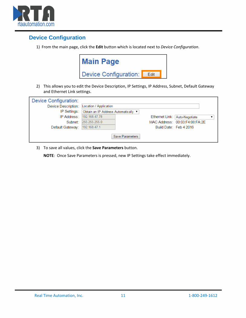
Device Configuration 1) From the main page, click the Edit button which is located next to Device Configuration.
2) This allows you to edit the Device Description, IP Settings, IP Address, Subnet, Default Gateway and Ethernet Link settings.
3) To save all values, click the Save Parameters button.
NOTE: Once Save Parameters is pressed, new IP Settings take effect immediately.
Real Time Automation, Inc. 11 1-800-249-1612

PLC Configuration 1) Click the PLC Configuration button under the CONFIGURATION section.
2) PLC Type: Select which PLC you are using. a. If using a Logix PLC, all processors are compatible. b. If using a PLC5E, then it must be: Series C, Revision N.1 or later; Series D, Revision E.1 or
later; or Series E, Revision D.1 or later. c. If using a SLC5/05, then it must be: Series A, Version OS501; or FRN5 Series B and Series
C or later. d. If using a NetENI module, select based on the Processor it is connected to. e. If connecting to an I/O Scanner, please see User Guide, Appendix B for more details.
3) IP Address: Enter the IP Address of the PLC. a. If using I/O Scanner, this is the IP Address of the PLC.
i. If the IP Address is 0.0.0.0, the gateway will accept messages from any device.
4) Controller Slot: Enter the slot that the Controller is located in. a. If you are using an Integrated Ethernet Card, enter slot 0. b. For Logix processors, this is NOT the slot of the Ethernet Adapter.
5) Communication Mode: Select whether to use unconnected or connected messaging.
a. Connected (Class 3 Explicit) (Default): Relies on reserved resources to transfer data to/from the PLC. This is more reliable than Unconnected Messaging.
b. Unconnected (UCMM): Relies on shared resources to transfer data to/from the PLC. This could result in message timeouts if there are a lot of devices fighting for these shared buffers.
6) Inter-Message Delay: The Inter-Message Delay is a forced delay for each request the gateway
sends to the PLC. a. This setting will affect the speed at which a message is delivered and the amount of
traffic the gateway adds to the network.
Real Time Automation, Inc. 12 1-800-249-1612

b. If set to 0, the gateway will communicate as fast as possible to the PLC and generate the most traffic.
c. In applications with a heavy network, it is recommended that you increase this delay to limit network traffic.
7) Heartbeat Tag/File: This Tag or File will act as an incremental counter for messages passed
though the gateway. a. For RSLogix5000 Family: This should be an INT Data Type Tag. b. For RSLogix500 Family: This should be an N Register. c. This can be used to monitor if the gateway has stopped communicating with the PLC.
Real Time Automation, Inc. 13 1-800-249-1612

TCP/IP Communication Setup From any page, click the TCP/IP Configuration button under the CONFIGURATION section.
Is my device a Server or Client? If the TCP/IP device you are connecting to needs to know the IP Address of our gateway, or is in charge of making the connection over the TCP port, then that TCP/IP device is a Client. The 490NBX needs to act as a Server.
If the Gateway is a Client Connecting to a Server Device
1) Enable: Check this box to enable any of the 10 possible ports. • These numbers (0-9) are used internally to identify the various connections for the ASCII
Configuration section. 2) Client: Check the Client checkbox if the gateway is connecting to a TCP/IP Server device. 3) IP Address: Enter the IP address of the Server that the gateway will open a TCP/IP Connection
to. • The combination of IP Address and TCP Port must match the device exactly in order for
the gateway to open a connection. 4) TCP Port: Enter the TCP Port Number that the Server is communicating on.
• The combination of IP Address and TCP Port must match the device exactly in order for the gateway to open a connection.
5) Inactivity Timeout: Enter the amount of time in seconds that the gateway will wait idle before closing the connection.
• The default value is set to 5 seconds. If communication is not occurring every 5 seconds, then you will see the TCP/IP Connection Attempts on the Diagnostics page increment. To fix, the Inactivity Timeout can be increased for the port or disabled by writing a value of 0.
6) Reconnect Delay: Enter the amount of time in seconds that the gateway will wait before attempting to reestablish a connection to the Server device.
• The default value is set to 10 seconds so that reconnect messages do not add additional stress to the network.
Real Time Automation, Inc. 14 1-800-249-1612

If a Client Device is Connecting to the Gateway Acting as a Server 1) Enable: Check this box to enable any of the 10 possible ports.
• These numbers (0-9) are used internally to identify the various connections for the ASCII Configuration section.
1) Client: Uncheck the Client checkbox if the gateway is being connected by a Client TCP/IP device. 2) IP Address: Enter the IP Address of the Client that the gateway will accept a TCP/IP connection
from. • Enter 0.0.0.0 if you want the gateway to listen for any IP Address to make the
Connection. • The combination of the IP Address and TCP/IP Port must match the device exactly in
order for the device to open a connection to the gateway. 3) TCP Port: Enter the TCP/IP Port Number on which the Client is communicating.
• The combination of the IP Address and TCP/IP Port must match the device exactly in order for the device to open a connection to the gateway.
4) Inactivity Timeout: Enter the amount of time in seconds that the gateway will wait idly before closing the connection.
• The default value is set to 5 seconds. If communication is not occurring every 5 seconds, then you will see the TCP/IP Connection Attempts on the Diagnostics page increment. To fix, the Inactivity Timeout can be increased for the port or disabled by writing a value of 0.
5) Reconnect Delay: This feature is disabled if the gateway is a Server.
Real Time Automation, Inc. 15 1-800-249-1612

Setting up ASCII to PLC Communication Click the ASCII Configuration button under the CONFIGURATION section.
Define PLC Tag / File 1) Data Type: Select the Data Type for the Tag / File Name that you defined in the PLC.
a. If PLC Type configured is I/O Scanner, then this field is not used. 2) Enter the Tag / File name you want the gateway to move the ASCII message to.
a. The Tag / File must be defined in the PLC and must match exactly. b. Most of the time, the Tag Name is defined within the Controller Scope of the PLC for
Read/Write Access. i. To configure our gateway for a Program Scope Tag, see Appendix D for
instructions. c. If PLC Type configured is I/O Scanner, then this field is not used.
Real Time Automation, Inc. 16 1-800-249-1612

Define ASCII Message Termination 1) To define an ASCII message, you must select one or more of the following end cases: Character
Count, Timer, or Delimiters. a. Character Count: Enter the max number of characters that the device could output.
Example: If your device sends a four digit temperature, set the length to 4. i. If using an INT Data Type, this is also the dimension size/2 + 1 of the Tag / File.
ii. If using a SINT Data Type, this is also the dimension size + 2 of the Tag / File. iii. For Controllers using RSLogix 5000, the range for each data type is:
♦ STRING/INT/SINT: 1-4096 characters ♦ STRING– If using more than 82 characters, a User Defined Data Type must
be created within the PLC and used. Refer to Appendix C for instructions. ♦ For Controllers using RSLogix 500, the range for each data type is:
♦ STRING: 1-82 characters ♦ INT: 1-200 characters ♦ SINT: Not Used
b. Timer: Use this option if your device sends data of varying lengths and does not have end delimiters. This is the amount of time we will wait after the last character of a message before considering the message complete.
c. Delimiters i. Start: Select how many Start Delimiters to look for in the ASCII message. Use
this feature if the ASCII message has common starting delimiter(s), (characters at the beginning of every message).
♦ The value of this first dropdown will either gray out or allow a delimiter to be selected from the next dropdown.
ii. End: Select how many End Delimiters to look for in the ASCII message. Use this feature if the ASCII message has common end delimiter(s). <CR><LF> is a common example.
♦ The value of this first dropdown will either gray out or allow a delimiter to be selected from the next dropdown.
iii. Remove Delimiters: If using any Start or End Delimiters and you do not want them to be sent to the PLC, then enable this checkbox.
Real Time Automation, Inc. 17 1-800-249-1612

Message Queue 1) Queue Size: Enter the number of complete messages you want the gateway to hold before
discarding. 2) Queue Full Behavior: If the Queue is full, the gateway will discard messages one of the following
ways: a. Discard New Data: Gateway will discard any new messages. b. Overwrite Oldest Data: Gateway will overwrite oldest message with new data.
Data Conversion 1) NULL Character Handling: Select how the gateway will handle the NULL Character.
a. None (Default): Does no additional conversion on the data before sending it to the PLC. b. Remove NULL: Removes all NULL characters from the ASCII Message before sending it to
the PLC.
Real Time Automation, Inc. 18 1-800-249-1612

Setting up PLC to ASCII Communication Click the ASCII Configuration button under the CONFIGURATION section.
Define PLC Tag / File 1) Data Type: Select the Data Type for the Tag / File Name that you defined in the PLC.
a. If PLC Type configured is I/O Scanner, then this field is not used. 2) Enter the Tag / File name that you want the gateway to monitor for messages.
a. The Tag / File must be defined in the PLC and must match exactly. b. Most of the time, the Tag Name is defined within the Controller Scope of the PLC for
Read/Write Access. i. To configure our gateway for a Program Scope Tag, see Appendix D for
instructions. c. If PLC Type configured is I/O Scanner, then this field is not used.
3) Character Count: Enter the maximum number of characters that the gateway can send to the ASCII device.
a. If using an INT Data Type, this is also the dimension size/2 + 1 of the Tag / File. b. If using a SINT Data Type, this is also the dimension size + 2 of the Tag / File c. For Controllers using RSLogix5000, the range for each data type is:
i. STRING/INT/SINT: 1-4096 characters. ii. STRING– If using more than 82 characters, a User Defined Data Type must be
created within the PLC and used. Refer to Appendix C for instructions. d. For Controllers using RSLogix500, the range for each data type is:
i. STRING: 1-82 characters ii. INT: 1-200 characters
iii. SINT: Not Used
Real Time Automation, Inc. 19 1-800-249-1612

Add Delimiters to ASCII Message 1) Delimiters: Configure the characters to add to the message.
a. Start: Use this feature to add a common starting delimiter(s) to messages being sent to the ASCII device.
i. The value of this first dropdown will either gray out or allow a delimiter to be selected from the next dropdown.
ii. Use this feature only if your ASCII device requires such delimiters. iii. All ASCII messages will receive the starting delimiters selected.
b. End: Use this feature to add a common end delimiter(s) to messages being sent to the ASCII device.
i. The value of this first dropdown will either gray out or allow a delimiter to be selected from the next dropdown.
ii. Use this feature only if your ASCII device requires such delimiters. iii. All ASCII messages will receive the end delimiters selected.
Data Conversion 1) Data Conversion:
a. None (Default): Does no additional conversion on the data before sending it from the gateway to the ASCII device.
b. Prepend NULL: Adds a NULL character to the beginning of each message that is to be sent from the gateway to the ASCII device.
c. Postpend NULL: Adds a NULL character to the end of each message that is to be sent from the gateway to the ASCII device.
Real Time Automation, Inc. 20 1-800-249-1612

Diagnostics and Troubleshooting
From any page, click the Diagnostics button under the DIAGNOSTICS section.
PLC Status PLC Status: Shows same information that is on the main page diagnostics. See section Diagnostics-Main Page for further explanations. Connection Attempts: Increments every time the 490NBX loses connection to the PLC and attempts to reconnect. Write Heartbeat to PLC: OK: Number of successful write messages to heartbeat Tag/File Name. Error: Number of failed write messages to heartbeat Tag/File Name. Last Error: Specific error information pertaining to the last failed heartbeat message to the PLC.
Port & Direction Selection Port Selection: Use the << and >> buttons to navigate to the desired port diagnostics. Direction Selection: Use the ASCII to PLC / PLC to ASCII tabs to select the direction you want to view.
TCP/IP Information TCP/IP Status:
Disabled: The selected port is not enabled. Initializing: The gateway is the Client and have sent a TCP/IP connection request to the TCP/IP Server device and is waiting for a response. Listening: The gateway is the Server and is listening for a connection request from the TCP/IP Client device. Connected: Good communication with the TCP/IP device.
Connection Attempts: This value increments every time the 490NBX loses connection to the TCP/IP device and attempts to reconnect.
NOTE: The PLC Status and TCP/IP Status must both be connected for data to appear in the Diagnostics web page.
Real Time Automation, Inc. 21 1-800-249-1612

Diagnostics and Troubleshooting – ASCII to PLC This page will automatically refresh to show the latest data.
Last message sent to PLC (chars): This buffer shows the last message that was successfully sent to the PLC. Next message stored in ASCII queue (chars – messages queued):
This buffer shows the next ASCII message waiting to be sent. This ASCII message will only be sent to the PLC if the Length field within the Tag/File is set to zero, indicating the last message has been processed.
-When using String Data Type, the .LEN needs to be set to 0. -When using INT Data Type, the 1st array index [0] needs to be set to 0. -When using SINT Data Type, the 1st and 2nd array index [0] & [1] needs to be set to 0.
Current message being processed (chars): This buffer shows the real time data that the ASCII device is sending out to the 490NBX gateway. All data in this buffer is pending due to one of the three end cases not being met. Those end cases are Character Count, Timer, and Delimiters. Send Test Message to PLC:
Use this field to send a test message to the PLC. • PLC and Port must be configured to use this feature. • This message will not work if buffer is already full. Message will be discarded.
Real Time Automation, Inc. 22 1-800-249-1612

Diagnostic Counters
ASCII Event: Delimiter: Increments if a successful ASCII message was received with delimiters being read.
Length: Increments if a successful ASCII message was received containing the max character count. Timeout: Increments if a successful ASCII message was received with the timer value being reached.
Discards: Increments if a message was thrown away due to the ASCII queue buffer being full. Read Handshake Message from PLC: OK: Increments when the length field is non-zero in the PLC.
Error: Increments when there is an error with the Tag/File in the PLC. Last Error: This will report the most recent error.
Note: Errors that show up here are reported from either the 490NBX or the PLC. For detailed errors and explanations, please see Appendix A. Write ASCII Message to PLC: OK: Increments with every successful message sent from ASCII to the PLC. Error: Increments when there is an error writing the Tag / File.
Last Error: This will report the most recent error found. Note: Errors that show up here are reported from either the 490NBX or the PLC. For detailed errors and explanations, please see Appendix A.
Real Time Automation, Inc. 23 1-800-249-1612

Diagnostics and Troubleshooting – PLC to ASCII This page will automatically refresh to show the latest data.
Last message sent to ASCII (chars):
This buffer shows the last message that was sent to the ASCII device. Data portion should be filled in first and then the Length field. When the Length is non-zero, the gateway will process it and then set to 0, indicating another message can be sent.
-When using String Data Type, length is set using the .LEN field. -When using INT Data Type, the length is the 1st array index [0]. -When using SINT Data Type, the length is the 1st and 2nd array index [0] & [1].
Send Test Message to ASCII: Use this field to bypass the PLC and send a test message out to the ASCII device from the gateway. All delimiter information configured in the ASCII Configuration section will be applied when a message is sent.
• PLC and Port must be configured to use this feature.
Real Time Automation, Inc. 24 1-800-249-1612

Diagnostic Counters Read ASCII Message from PLC: OK: Increments with every read request for the length field from the gateway.
Error: Increments when there is an error with the Tag/File Name in the PLC. Last Error: This will report the most recent error found.
Note: Errors that show up here are reported from either the 490NBX or the PLC. For detailed errors and explanations, please see Appendix A. Write Handshake Message to PLC: OK: Increments with every successful message sent from PLC to the ASCII device. Error: Increments when there is an error with the Tag/File Name in the PLC.
Last Error: This will report the most recent error found. Note: Errors that show up here are reported from either the 490NBX or the PLC. For detailed errors and explanations, please see Appendix A.
Real Time Automation, Inc. 25 1-800-249-1612

Diagnostics and Troubleshooting – LEDs When both LEDs blink Red alternating like railroad crossing lights, the gateway’s configuration has changed. A reboot is necessary for the new configuration to take effect.
If the PLC Type of the gateway is configured for I/O Scanner, LED 2 has special meaning. See Appendix B for further information.
LED 1 : ASCII
Blink Green
No messages sent or received.
Solid Green
All TCP Connections are valid and are communicating with the gateway within the Inactivity Timeout configured.
Blink Red
1) Data Timeout – No data within Inactivity Timeout.
2) Queue is full and gateway is discarding messages.
Solid Red
1) No TCP Devices configured/enabled.
2) No ASCII Devices configured/enabled.
Off Ethernet cable is unplugged.
LED 2 : Allen-Bradley PLC
Blink Green
No messages sent or received.
Solid Green
Connection to PLC is valid and communication is good.
Blink Red
1) Had good connection to PLC but have since lost it.
2) No connection has ever been made to the PLC but IP Address is configured.
Solid Red
1) No PLC Configured.
2) No IP Address entered for PLC.
Off Ethernet cable is unplugged.
Real Time Automation, Inc. 26 1-800-249-1612

Diagnostics – Main Page For a snapshot diagnostic view of the gateway, go to the Main Page. This page will automatically refresh.
PLC Status This shows the Status of the PLC Connection. Possible values are:
1) No PLC Configured – Displays when either a PLC Type is not selected and/or the IP address is set to 0.0.0.0.
2) Connection Request Sent to PLC – Displays when a valid PLC Type and IP Address is configured and gateway is attempting to connect to the PLC.
3) Connection retry delay – Displays when a valid PLC Type and IP Address is configured and gateway tried to connect to the PLC but failed.
• Verify the PLC Type, IP Address, Controller Slot, and Communication Mode to ensure information entered is correct.
• Normally, Connection Attempts will also increment with this PLC Status. 4) I/O Adapter – Displays when PLC Type is selected to I/O Scanner
ASCII Status This shows the overall status of the ASCII devices. Possible values are:
1) No TCP/IP devices Configured – Displays when no ports are configured on the TCP/IP Configuration page.
2) No Messages RX or TX – Displays when at least 1 port is configured and no ASCII messages have been successfully sent to the PLC or PLC messages sent to the ASCII device.
• Verify the ASCII Configuration page is correct. 3) Queue Full – Discarding Messages – Displays when the buffer in the gateway is full and incoming
messages are being discarded. This means the ASCII device is sending data faster than the PLC is clearing out the length field in the tag/register.
Real Time Automation, Inc. 27 1-800-249-1612

Device Status There are 4 columns that make up this status. The status reflected here show the current status for configured parameters. This means that any pending changes made to that parameter since it was last powered up will not display.
Example: If since the last power up, the TCP/IP port has since been disabled, you will need to restart the gateway in order to see that port row disappear from the main page.
1) Left column: The left most column indicates which port the status is for. • 0 - 9 – to represent the possible TCP/IP Ports on the gateway
2) TCP/IP Status: Status of the TCP/IP connection for that port. Possible statuses are: • “Disabled”: The selected port is not enabled. • “Initializing”: The gateway is the Client and have sent a TCP/IP connection request to the
TCP/IP Server device and is waiting for a response. • “Listening”: The gateway is the Server and is listening for a connection request from the
TCP/IP Client device. • “Connected”: Good communication with the TCP/IP device.
3) ASCII to PLC Status and PLC to ASCII Status columns: The two right columns break down the communication on that specific port by direction. Possible statuses are:
• “Disabled” – Indicates that the direction on that port is not enabled. • “Tag/File Not Yet Defined” – Indicates that the port and direction are enabled, but the
tag/file name is blank. o Only when PLC Type is not I/O Adapter
• A decimal value – Represents number of complete messages that the gateway has received or the number of messages that we have received from the PLC and transmitted to the ASCII device.
4) Background colors: • White – Even row number with no errors for that port and direction. • Gray – Odd row number with no errors for that port and direction. • Read – Error for at least 1 of the reasons listed below:
i. PLC Type is not configured ii. PLC Type is configured (not I/O Adapter) but IP address is 0.0.0.0
iii. Error Count on Diagnostics page is non-zero for that direction. NOTE: The area will display with a red background if there are any errors listed on the diagnostics page, even if they are old. To remove this red background, go to the Diagnostics page for that port and direction and clear counters.
Real Time Automation, Inc. 28 1-800-249-1612

Save/Load the Configuration
Click the Export/Import Config button under the OTHER section.
Export Configuration 1) Click the Save Configuration to PC button. 2) A prompt will then ask the type of file to save as. Any type will suffice. 3) This will save all of the configuration except for the Gateway’s IP Network Settings, since this
must be unique. 4) Save this file to the PC.
Import Configuration 1) Click Choose File and search for the configuration to load to the 490NBX. 2) Click Load Configuration. If successful, you will be redirected to the main page and be forced to
reboot the gateway. a. If the load failed, you will be prompted with an error.
Real Time Automation, Inc. 29 1-800-249-1612

Utilities The Utilities screen offers additional features and functionality in the gateway including Logging, Security, Update Firmware Capability, and Restart Options.
Here you can also: • Configure logging settings for diagnostic purposes. • Configure security settings. • Upgrade the firmware right from the webpage. • Various options to reset the gateway.
Revision Listing Displays the full catalog number of the gateway. Have this number ready when contacting a RTA Technical Support Specialist.
Diagnostics Logging Most users will not need to do anything with this feature. If there are problems with the gateway, a RTA Technical Support Specialist will direct you in how to use this feature.
Real Time Automation, Inc. 30 1-800-249-1612

Security Configuration Click on the Security button to configure security for a single username and password.
1) Log Out Timer: The system will automatically log inactive users off after this period of time. 2) Username: Enter a username, max of 30 characters, case sensitive. 3) Password: Enter a password for the username, max of 30 characters, case sensitive. 4) Hint: A helpful reminder of what the password is. 5) Admin Information: Enter contact information in case username/password is forgotten. 6) Click the Save Parameters button to save.
Security - Log In 1) Username: Name of the user to login. 2) Password: Password of the user to login. 3) Log In: If login is successful, the user will be redirected to the Main Page. 4) Display Hint: Displays the hint specified for the user if one was set up. 5) Reset Password: This is used to reset security settings. Confirm reset password must be selected
to confirm this action. Once confirmed, there is a 15 minute window to do a hard reset of the gateway by physically removing and restoring power from the gateway. Once power is restored, you may navigate to the IP address of the gateway as normal.
Real Time Automation, Inc. 31 1-800-249-1612

Upgrade Firmware Click the Upgrade Firmware button if you need to upgrade firmware for the gateway.
From here, click Choose File and select the XXXXX_APP.s19 file. Once the file name appears next to Application File, click the Upgrade Firmware button.
The firmware will load and will automatically reboot the gateway after 30 seconds and redirect the webpage to the Main Page when finished.
Reset Gateway There are 3 options to reset the 490NBX.
• Restart the Gateway – Saves the current settings of the gateway and performs a software reboot.
• Reset to Last Powerup – Brings the device back to its last power up settings. • Reset to Shipped Defaults – Brings the device back to its original manufacturing defaults, except
for the IP Address. To reset just the IP Address, see Intelligent Reset Button for instructions.
Once an option is selected, click the Reset button to execute.
Real Time Automation, Inc. 32 1-800-249-1612

Intelligent Reset Button If the IP Address of the gateway is forgotten or unknown, there is an easy way to recover the IP Address using a reset button on the hardware.
1) On the side of the gateway with the SD card slot, there is a small pinhole. Using a small paperclip, press the button through this pinhole and hold the button for at least 5 seconds.
2) After 5 seconds, the unit will acknowledge the command and the Comm LED (see section Diagnostics and Troubleshooting – LEDs) will go to Blink Green at 100ms.
3) Release the button and the gateway will reset to default DHCP IP settings. (Refer to the Accessing_Browser_Configuration doc on the cd to setup DHCP on your PC).
Real Time Automation, Inc. 33 1-800-249-1612

Save and Replace Configuration using SD Card This function saves the gateway’s configuration to an SD Card. If the SD card is placed in another unit, the configuration on the SD card will automatically populate the gateway on power up.
This SD Card replaces every configurable field in the gateway, INCLUDING IP Address, Subnet Mask, and Default Gateway.
Data Transfer To/From SD Card Data is written to the SD Card if no current configuration is found on the SD card and when a configuration change is saved.
Data is written from the SD Card upon power up. If the SD Card contains a configuration that differs in any way from the configuration already in the gateway the configuration from the SD card will be applied.
NOTE: When data is being written from the SD Card to the gateway, it will take up to 30 seconds for the data transfer to be completed. During this time, the gateway cannot be accessed via the webpage.
Using IP Setup with SD Card When an SD Card is present and an IP Address is modified through IPSetup.exe, a popup will appear after the Set button is pressed. This is intended as an extra precaution to ensure that the IP Address should be modified from what is currently stored in the SD Card.
1. Enter a UserName of RTA. 2. Enter a Password of RTA. 3. Press OK. 4. This will then update the IP Address of the gateway and the SD Card with what was set through
IPSetup.exe.
Real Time Automation, Inc. 34 1-800-249-1612

Appendix A: Error Definitions
Error Status Name Description
0x00 Success Service was successful
0x01 Controller Slot Doesn’t Exist Connection related service failed along the connection path
0x02 Resource unavailable Resources needed for the object requested service were unavailable
0x03 Invalid parameter value See Error 0x20
0x04 Incorrect Tag Data Type
Tag Name Doesn’t Match (ext: 0000h)
Path segment identifier or the segment syntax was not understood by the processing node. Path processing shall stop when a path segment error is encountered
0x05 Incorrect Controller Type The path is referencing an object class, instance or structure element that is not known or is not contained in the processing node. Path processing shall stop when a path destination unknown error is encountered
0x06 Partial transfer Only part of the expected data was transferred
0x07 Connection Lost The messaging connection was lost
0x08 Incorrect Controller Slot The requested service was not implemented or was not defined for this object class/instance
0x09 Invalid attribute value Invalid attribute data detected
0x0A Attribute list error An attribute in the Get_Attribute_List or Set_Attribute_List response has a non-zero status
0x0B Already in requested mode / state The object is already in the mode/state being requested by the service
0x0C Object state conflict The object cannot perform the requested service in its current mode/state
0x0D Object already exists The requested instance of object to be created already exists
0x0E Attribute not settable A request to modify a non-modifiable attribute was received
0x0F Privilege violation A permission/privilege check failed
Real Time Automation, Inc. 35 1-800-249-1612

0x10 Device state conflict The device’s current mode/state prohibits the execution of the requested service
0x11 Reply data too large The data to be transmitted in the response buffer is larger than the allocated response buffer
0x12 Fragmentation of a primitive value The service specified an operation that is going to fragment a primitive data value
0x13 Not enough data The service did not supply enough data to perform the specified operation
0x14 Attribute not supported The attribute specified in the request is not supported
0x15 Too much data The service supplied more data than was expected
0x16 Object does not exist The object specified does not exist in the device
0x17 Server fragmentation sequence The fragmentation sequence for this service is not currently active for this data
0x18 No stored attribute data The attribute data of this object was not saved prior to the requested service
0x19 Store operation failure The attribute data of this object was not saved due to a failure during the attempt
0x1A Routing failure, request packet
too large
The service request packet was too large for transmission on a network in the path to the destination. The routing device was forced to abort the service
0x1B Routing failure, response packet
too large
The service response packet was too large for transmission on a network in the path from the destination. The routing device was forced to abort the service
0x1C Missing attribute list entry data The service did not supply an attribute in a list of attributes that was needed by the service to perform the requested behavior
0x1D Invalid attribute value list The service is returning the list of attributes supplied with status information for those attributes that were invalid
Real Time Automation, Inc. 36 1-800-249-1612

0x1E Embedded server error An embedded service resulted in an error: This can mean the Controller Slot, IP Address or Tag Name does not match. The Tag is not defined in the Controller Scope within the PLC, or the Tag does not have Read/Write privileges.
0x1F Vendor specific error A vendor specific error has been encountered. The Additional Code Field of the Error Response defines the particular error encountered. Use of this General Error Code should only be performed when none of the Error Codes presented in this table or within an Object Class definition accurately reflect the error
0x20 Invalid parameter A parameter associated with the request was invalid. This code is used when a parameter does not meet the requirements of this specification and/or the requirements defined in an Application Object Specification
0x21 Write once value or medium already written
An attempt was made to write to a write-once medium that has already been written, or to modify a value that cannot be changed once established
0x22 Invalid reply received An invalid reply is received. This status code can serve for other causes of invalid replies
0x23 Buffer Overflow The message received is larger than the receiving buffer can handle. The entire message was discarded.
0x24 Message format error The format of the received message is not supported by the server
0x25 Key failure in path The key segment that was included as the first segment in the path does not match the destination module. The object specific status shall indicate which part of the key check failed
0x26 Path size invalid The size of the path which was sent with the Service Request is either not large enough for all the Requests to be routed to an object or too much routing data was included
0x27 Unexpected attribute An attempt was made to set an attribute that is not able to be set at this time
Real Time Automation, Inc. 37 1-800-249-1612

0x28 Invalid member ID The Member ID specified in the request does not exist in the specified Class/Instance/Attribute
0x29 Member not settable A request to modify a non-modifiable member was received
0x2C Attribute not gettable A request to read a non-readable attribute was received
Real Time Automation, Inc. 38 1-800-249-1612

Appendix B: I/O Messaging - Configuration (Rev 7.03 or Later) In order to enable I/O Messaging, under the PLC Type dropdown select I/O Scanner on the PLC Configuration page. Once you enable I/O Messaging, the Tag Name and Data Type in the ASCII to PLC and PLC to ASCII direction will not be used.
1. Set up the 490NBX as a Generic Ethernet Module into the Ethernet module I/O tree 2. Set the Data Format to “Data SINT” 3. Input Assembly: 100 (0x64) - Input Size: 416 Bytes 4. Output Assembly: 112 (0x70) - Output Size: 416 Bytes 5. Configuration Assembly: Any number (unused) - Configuration Size: 0 bytes
Input / Output Assembly Byte Breakdown Input Assembly (ASCII to PLC) Port 0: Input Assembly (ASCII to PLC) Port 1:
- Bytes 0-1: Output Handshake - Bytes 208-209: Output Handshake
- Bytes 2-3: Input Sequence Number - Bytes 210-211: Input Sequence Number
- Bytes 4-7: Input Length - Bytes 212-215: Input Length
- Bytes 8-207: Input Data (0-200 bytes) - Bytes 216-415: Input Data (0-200 bytes)
Output Assembly (PLC to ASCII) Port 0: Output Assembly (PLC to ASCII) Port 1:
- Bytes 0-1: Input Handshake - Bytes 208-209: Input Handshake
- Bytes 2-3: Output Sequence Number - Bytes 210-211: Output Sequence Number
- Bytes 4-7: Output Length - Bytes 212-215: Output Length
- Bytes 8-207: Output Data (0-200 bytes) - Bytes 216-415: Output Data (0-200 bytes)
Real Time Automation, Inc. 39 1-800-249-1612

Input / Output Assembly Handshaking Breakdown ASCII to PLC
The PLC monitors the Input Sequence Number for a non-zero value that doesn’t match the Input Handshake. This indicates new data is ready for processing.
Upon receiving new data, the PLC reads the length of the data and processes it (up to 200 bytes). The PLC then echoes the Input Sequence Number into the Input Handshake. This is the indication to the 490NBX that the message was processed.
New messages from the 490NBX are only written to the PLC when the Input Sequence Number matches the Input Handshake. All other messages are queued in the 490NBX until the queue is full. Messages are then discarded based on the discard rules defined by the user.
The Sequence Number will roll over to 1 after 65535.
PLC to ASCII
If the Output Sequence Number matches the Output Handshake, the PLC can write a new message to the 490NBX.
The PLC must write the Output Length and Output Data first, then increment the Output Sequence Number.
Once the message is processed by the 490NBX, the Output Handshake is echoed with the Last Output Sequence Number.
Zero is an invalid value for the Output Sequence Number.
Real Time Automation, Inc. 40 1-800-249-1612

Input / Output Assembly Diagnostics Breakdown When I/O Messaging is used, only the following counters or statuses are used on the Diagnostics page:
• The ASCII to PLC buffer display: - Last message sent to PLC - Next message stored in ASCII queue - Current message being processed - Send Test Message to PLC - ASCII Event counters
• PLC to ASCII buffer display: - Last message received from PLC - Send Test Message to ASCII
I/O Adapter Comm LED 2 This LED shows the following states when the PLC Type of the gateway is configured for I/O Scanner only.
• Solid Green: Gateway is connected and communicating. • Blink Green: Gateway is in start up state and is waiting for a connection. • Blink Red: A data timeout has occurred. The Data Inactivity period, or the RPI value
configured in the PLC when a connection is made, has been reached. • Off: Gateway’s Ethernet cable is unplugged.
Real Time Automation, Inc. 41 1-800-249-1612

Appendix C: Create User Defined Tag in RSLogix 5000 1) Within RSLogix 5000, click on Data Types and select Strings.
2) Right click on String and select New String Type. Give the new data type a name. 3) Select the max number of characters to be transferred. 4) When creating the tag name in the PLC, select the name of the new user defined data type you
just created.
Real Time Automation, Inc. 42 1-800-249-1612

Appendix D: How to Access Program Scope Tags in RSLogix5000 1) If you are using a tag that does not display in the list of tags when the scope is set to Controller
Scope. EX: In the picture below, the Controller is set to “test2”.
2) In the example below, the tag “AnotherTag” is setup in Program Scope named, “AnotherProgram”:
3) To access this tag “AnotherTag” in scope “AnotherProgram”, we need to enter it into our gateway using the following syntax:
Tag Name = “PROGRAM:ProgramName.TagName” where ProgramName = Scope name & TagName = Actual Tag Name
In the previous example, it would be the following: “PROGRAM:AnotherProgram.AnotherTag”
Real Time Automation, Inc. 43 1-800-249-1612