4.8SP 3.6SP 24 Bit System Processor · Operating Manual - PROTEA 4.8SP and 3.6SP System Processors...
16
ASHLY AUDIO INC. 847 Holt Road Webster, NY 14580-9103 Phone: (585) 872-0010 Toll-Free: (800) 828-6308 Fax: (585) 872-0739 www.ashly.com 4.8SP 3.6SP 24 Bit System Processor Operating Manual Digital Audio Products
Transcript of 4.8SP 3.6SP 24 Bit System Processor · Operating Manual - PROTEA 4.8SP and 3.6SP System Processors...
ASHLY AUDIO INC.847 Holt Road Webster, NY 14580-9103 Phone: (585) 872-0010
Toll-Free: (800) 828-6308 Fax: (585) 872-0739www.ashly.com
4.8SP3.6SP
24 Bit System Processor
Operating Manual
Digital Audio Products
Operating Manual - PROTEA 4.8SP and 3.6SP System Processors
2
Table Of Contents
1 INTRODUCTION . . . . . . . . . . . . . . . . . . . . . . . . . . . . . . . . . . . . . . . . . . . . . . . . . 41.1 Audio Features . . . . . . . . . . . . . . . . . . . . . . . . . . . . . . . . . . . . . . . . . . . . . . . . . . . 41.2 User Interface . . . . . . . . . . . . . . . . . . . . . . . . . . . . . . . . . . . . . . . . . . . . . . . . . . . . 4
2 UNPACKING . . . . . . . . . . . . . . . . . . . . . . . . . . . . . . . . . . . . . . . . . . . . . . . . . . . . . 4
3 AC POWER REQUIREMENTS . . . . . . . . . . . . . . . . . . . . . . . . . . . . . . . . . . . . 4
4 FRONT PANEL CONTROL FEATURES . . . . . . . . . . . . . . . . . . . . . . . . . . . 54.1 Function Keys and Data Wheel . . . . . . . . . . . . . . . . . . . . . . . . . . . . . . . . . . . . . 54.2 Presets . . . . . . . . . . . . . . . . . . . . . . . . . . . . . . . . . . . . . . . . . . . . . . . . . . . . . . . . . 54.3 Input Select . . . . . . . . . . . . . . . . . . . . . . . . . . . . . . . . . . . . . . . . . . . . . . . . . . . . . 54.4 Output Select . . . . . . . . . . . . . . . . . . . . . . . . . . . . . . . . . . . . . . . . . . . . . . . . . . . . 54.5 LED Indicators . . . . . . . . . . . . . . . . . . . . . . . . . . . . . . . . . . . . . . . . . . . . . . . . . . 54.6 Audio Functions . . . . . . . . . . . . . . . . . . . . . . . . . . . . . . . . . . . . . . . . . . . . . . . . . 6 4.6a Gain . . . . . . . . . . . . . . . . . . . . . . . . . . . . . . . . . . . . . . . . . . . . . . . . . . . . . . . . 6 4.6b EQ . . . . . . . . . . . . . . . . . . . . . . . . . . . . . . . . . . . . . . . . . . . . . . . . . . . . . . . . . 6 4.6c Delay . . . . . . . . . . . . . . . . . . . . . . . . . . . . . . . . . . . . . . . . . . . . . . . . . . . . . . . 7 4.6d Crossover . . . . . . . . . . . . . . . . . . . . . . . . . . . . . . . . . . . . . . . . . . . . . . . . . . . 8 4.6e Limit . . . . . . . . . . . . . . . . . . . . . . . . . . . . . . . . . . . . . . . . . . . . . . . . . . . . . . 104.7 Other Functions . . . . . . . . . . . . . . . . . . . . . . . . . . . . . . . . . . . . . . . . . . . . . . . . . 10 4.7a Recall . . . . . . . . . . . . . . . . . . . . . . . . . . . . . . . . . . . . . . . . . . . . . . . . . . . . . 10 4.7b Save . . . . . . . . . . . . . . . . . . . . . . . . . . . . . . . . . . . . . . . . . . . . . . . . . . . . . . 11 4.7c Copy . . . . . . . . . . . . . . . . . . . . . . . . . . . . . . . . . . . . . . . . . . . . . . . . . . . . . . 11 4.7d Mute . . . . . . . . . . . . . . . . . . . . . . . . . . . . . . . . . . . . . . . . . . . . . . . . . . . . . . 11 4.7e Utilities . . . . . . . . . . . . . . . . . . . . . . . . . . . . . . . . . . . . . . . . . . . . . . . . . . . . 11 4.7f Factory Reset . . . . . . . . . . . . . . . . . . . . . . . . . . . . . . . . . . . . . . . . . . . . . . . 11
5 INTERCONNECT FEATURES . . . . . . . . . . . . . . . . . . . . . . . . . . . . . . . . . . . . 125.1 Audio Connections . . . . . . . . . . . . . . . . . . . . . . . . . . . . . . . . . . . . . . . . . . . . . . 125.2 USB Connection . . . . . . . . . . . . . . . . . . . . . . . . . . . . . . . . . . . . . . . . . . . . . . . . 125.3 RS-232 Data Connection . . . . . . . . . . . . . . . . . . . . . . . . . . . . . . . . . . . . . . . . . 12
6 PROTEA NE SOFTWARE . . . . . . . . . . . . . . . . . . . . . . . . . . . . . . . . . . . . . . . . . 12
7 TROUBLESHOOTING . . . . . . . . . . . . . . . . . . . . . . . . . . . . . . . . . . . . . . . . . . . . 14
8 SPECIFICATIONS . . . . . . . . . . . . . . . . . . . . . . . . . . . . . . . . . . . . . . . . . . . . . . . . 14
9 WARRANTY INFORMATION . . . . . . . . . . . . . . . . . . . . . . . . . . . . . . . . . . . . 15
10 BLOCK DIAGRAM . . . . . . . . . . . . . . . . . . . . . . . . . . . . . . . . . . . . . . . . . . . . . . . 16
3
Operating Manual - PROTEA 4.8SP and 3.6SP System Processors
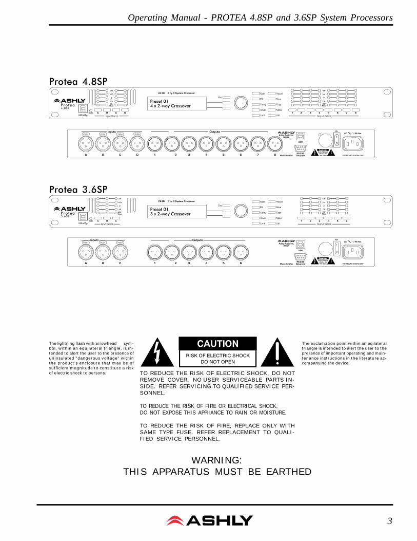
WARNING:THIS APPARATUS MUST BE EARTHED
The exclamation point within an eqilateraltriangle is intended to alert the user to thepresence of important operating and main-tenance instructions in the literature ac-companying the device.
The lightning flash with arrowhead sym-bol, within an equilateral triangle, is in-tended to alert the user to the presence ofuninsulated "dangerous voltage" withinthe product's enclosure that may be ofsufficient magnitude to constitute a riskof electric shock to persons. TO REDUCE THE RISK OF ELECTRIC SHOCK, DO NOT
REMOVE COVER. NO USER SERVICEABLE PARTS IN-SIDE. REFER SERVICING TO QUALIFIED SERVICE PER-SONNEL.
TO REDUCE THE RISK OF FIRE OR ELECTRICAL SHOCK,DO NOT EXPOSE THIS APPlIANCE TO RAIN OR MOISTURE.
TO REDUCE THE RISK OF FIRE, REPLACE ONLY WITHSAME TYPE FUSE. REFER REPLACEMENT TO QUALI-FIED SERVICE PERSONNEL.
CAUTIONRISK OF ELECTRIC SHOCK
DO NOT OPEN
Protea 4.8SP
Protea 3.6SP
Operating Manual - PROTEA 4.8SP and 3.6SP System Processors
4
1. INTRODUCTION
Thank you for your purchase of this Ashly Protea 4.8SP or 3.6SP Digital Crossover/SystemProcessor. The Protea series builds on the tradition of quality and value which has earned Ashly itsplace as a market leader in crossovers, equalization, and signal processing.
The 4.8SP has four inputs and eight outputs, while the 3.6SP has three inputs and six outputs.The front panel interface allows quick access to all control parameters by offering dedicated functionbuttons, eliminating the need for hidden sub-menus. For even faster set-ups and stronger visualizationof Input/Output routing, EQ, and Filter curves, a USB port is provided for use with Windows™ ProteaNE Software. Full control by third party controllers is also available via RS-232.
1.1 AUDIO FEATURES
The Protea 4.8SP and 3.6SP utilize state of the art DSP technologies, beginning with 24 bit, 48kHz delta-sigmaA/D converters with 128x oversampling. Digital processing includes Gain, Parametric EQ, Shelving Filters, Time Delay,Crossover Functions, Compression, Limiting, and Matrix Routing, all taking place in twin 120MHz Motorola DSP56362high performance DSP processors. D/A conversion uses 24 bit delta-sigma converters with 128x oversampling. Allinputs and outputs are precision balanced and RF protected using XLR connectors.
1.2 USER INTERFACE
Front Panel Interface: A backlit 2 x 20 character LCD displays channel and function settings. Dedicatedbuttons provide access to all audio functions and system tools. The display indicates the current preset number, thensubsequently shows the selected input or output and its active control parameters. Five segment LED arrays on eachinput and output provide audio level information and mute status.
Protea NE Software: The computer interface uses Ashly PROTEA NE SOFTWARE for Windows, which allowscomplete PC control of the unit through a USB jack. Protea NE software is supplied with each unit, or can be down-loaded at no cost from the Ashly web site. Advantages of using the software include greater preset capacity, and a veryintuitive visual representation of the audio routing and control process.
2. UNPACKING
As a part of our system of quality control, every Ashly product is carefully inspected before leaving the factoryto ensure flawless appearance. After unpacking, please inspect for any physical damage. Save the shipping carton andall packing materials, as they were carefully designed to minimize the possibility of transportation damage should theunit again require packing and shipping. In the event that damage has occurred, immediately notify your dealer so thata written claim to cover the damages can be initiated. The right to any claim against a public carrier can be forfeited ifthe carrier is not notified promptly and if the shipping carton and packing materials are not available for inspection bythe carrier. Save all packing materials until the claim has been settled.
3. AC POWER REQUIREMENTS
Note: The AC power switch is on the back panel. The Protea 4.8SP and 3.6SP use a universal input powersupply which will accept any line voltage in the range of 100VAC to 240VAC, 50-60Hz. A standard IEC-320 groundedAC inlet is provided on the rear panel to accept the detachable power cord. Never remove the AC earth groundconnection to the unit. In the event of fuse failure, refer the product to a qualified service technician for fuse replace-ment, replacing only with the same type and rating fuse.
5
Operating Manual - PROTEA 4.8SP and 3.6SP System Processors
4. FRONT PANEL CONTROL FEATURES
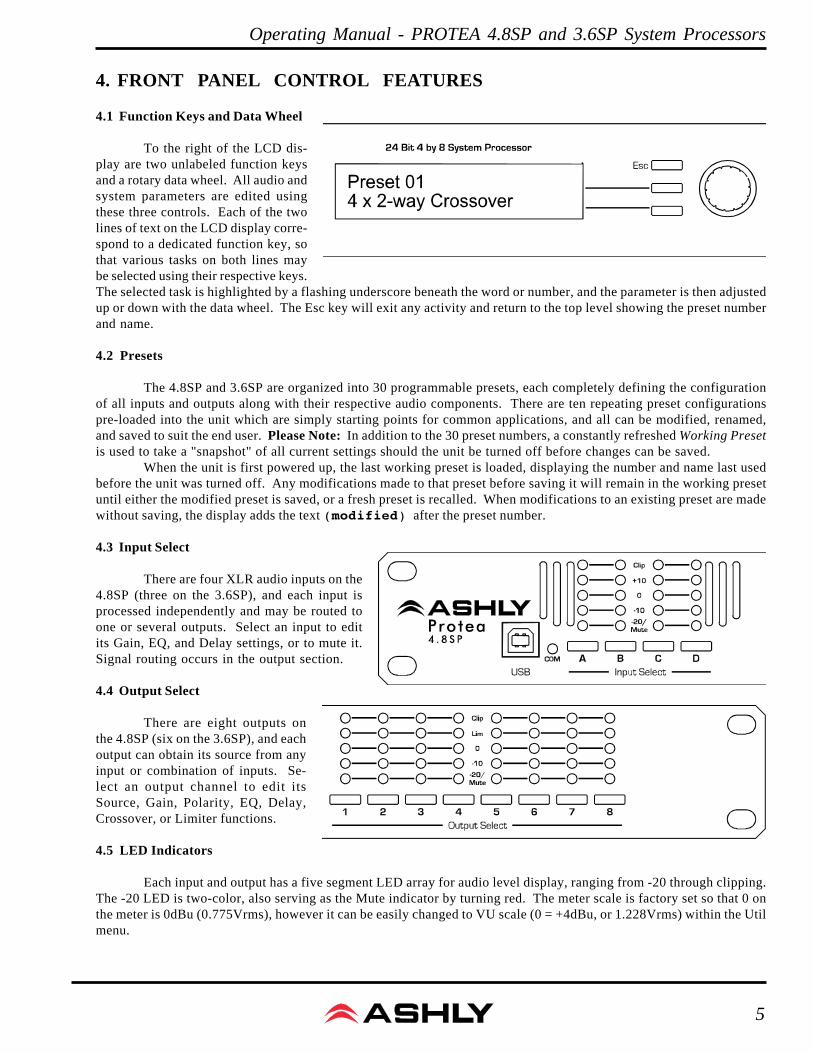
4.1 Function Keys and Data Wheel
To the right of the LCD dis-play are two unlabeled function keysand a rotary data wheel. All audio andsystem parameters are edited usingthese three controls. Each of the twolines of text on the LCD display corre-spond to a dedicated function key, sothat various tasks on both lines maybe selected using their respective keys.The selected task is highlighted by a flashing underscore beneath the word or number, and the parameter is then adjustedup or down with the data wheel. The Esc key will exit any activity and return to the top level showing the preset numberand name.
4.2 Presets
The 4.8SP and 3.6SP are organized into 30 programmable presets, each completely defining the configurationof all inputs and outputs along with their respective audio components. There are ten repeating preset configurationspre-loaded into the unit which are simply starting points for common applications, and all can be modified, renamed,and saved to suit the end user. Please Note: In addition to the 30 preset numbers, a constantly refreshed Working Presetis used to take a "snapshot" of all current settings should the unit be turned off before changes can be saved.
When the unit is first powered up, the last working preset is loaded, displaying the number and name last usedbefore the unit was turned off. Any modifications made to that preset before saving it will remain in the working presetuntil either the modified preset is saved, or a fresh preset is recalled. When modifications to an existing preset are madewithout saving, the display adds the text (modified) after the preset number.
4.3 Input Select
There are four XLR audio inputs on the4.8SP (three on the 3.6SP), and each input isprocessed independently and may be routed toone or several outputs. Select an input to editits Gain, EQ, and Delay settings, or to mute it.Signal routing occurs in the output section.
4.4 Output Select
There are eight outputs onthe 4.8SP (six on the 3.6SP), and eachoutput can obtain its source from anyinput or combination of inputs. Se-lect an output channel to edit itsSource, Gain, Polarity, EQ, Delay,Crossover, or Limiter functions.
4.5 LED Indicators
Each input and output has a five segment LED array for audio level display, ranging from -20 through clipping.The -20 LED is two-color, also serving as the Mute indicator by turning red. The meter scale is factory set so that 0 onthe meter is 0dBu (0.775Vrms), however it can be easily changed to VU scale (0 = +4dBu, or 1.228Vrms) within the Utilmenu.
Operating Manual - PROTEA 4.8SP and 3.6SP System Processors
6
4.6 Audio Functions
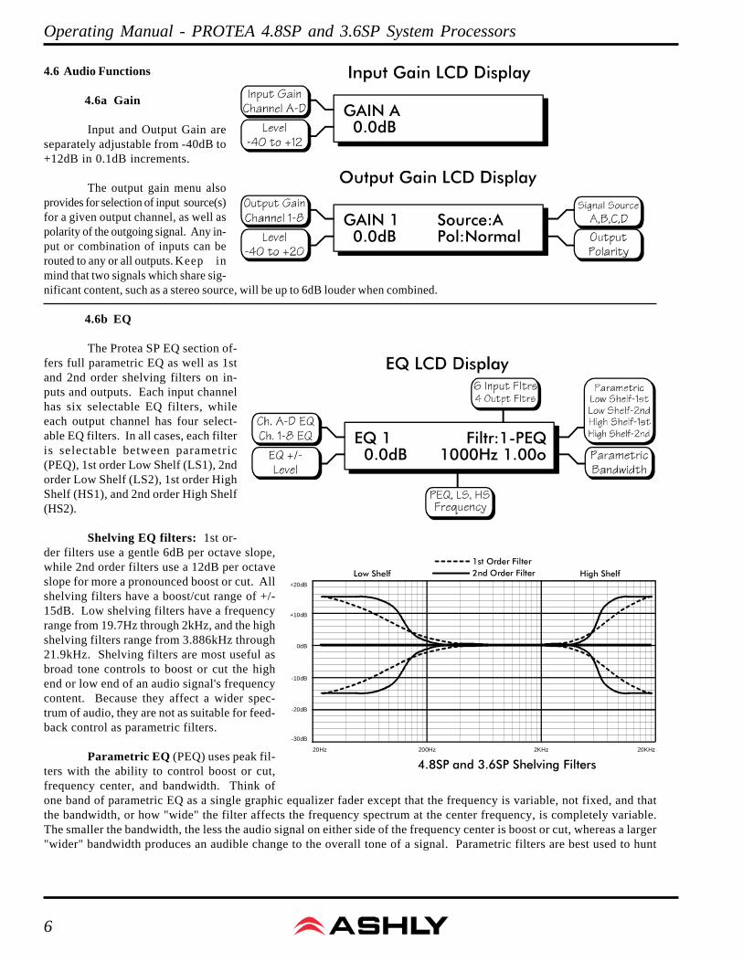
4.6a Gain
Input and Output Gain areseparately adjustable from -40dB to+12dB in 0.1dB increments.
The output gain menu alsoprovides for selection of input source(s)for a given output channel, as well aspolarity of the outgoing signal. Any in-put or combination of inputs can berouted to any or all outputs. Keep inmind that two signals which share sig-nificant content, such as a stereo source, will be up to 6dB louder when combined.
4.6b EQ
The Protea SP EQ section of-fers full parametric EQ as well as 1stand 2nd order shelving filters on in-puts and outputs. Each input channelhas six selectable EQ filters, whileeach output channel has four select-able EQ filters. In all cases, each filteris selectable between parametric(PEQ), 1st order Low Shelf (LS1), 2ndorder Low Shelf (LS2), 1st order HighShelf (HS1), and 2nd order High Shelf(HS2).
Shelving EQ filters: 1st or-der filters use a gentle 6dB per octave slope,while 2nd order filters use a 12dB per octaveslope for more a pronounced boost or cut. Allshelving filters have a boost/cut range of +/-15dB. Low shelving filters have a frequencyrange from 19.7Hz through 2kHz, and the highshelving filters range from 3.886kHz through21.9kHz. Shelving filters are most useful asbroad tone controls to boost or cut the highend or low end of an audio signal's frequencycontent. Because they affect a wider spec-trum of audio, they are not as suitable for feed-back control as parametric filters.
Parametric EQ (PEQ) uses peak fil-ters with the ability to control boost or cut,frequency center, and bandwidth. Think ofone band of parametric EQ as a single graphic equalizer fader except that the frequency is variable, not fixed, and thatthe bandwidth, or how "wide" the filter affects the frequency spectrum at the center frequency, is completely variable.The smaller the bandwidth, the less the audio signal on either side of the frequency center is boost or cut, whereas a larger"wider" bandwidth produces an audible change to the overall tone of a signal. Parametric filters are best used to hunt
200Hz 2KHz 20KHz20Hz
0dB
-10dB
-20dB
+10dB
+20dB
-30dB
Low Shelf High Shelf
4.8SP and 3.6SP Shelving Filters
2nd Order Filter1st Order Filter
GAIN A 0.0dB
GAIN 1 0.0dB
Source:APol:Normal
EQ 1 0.0dB
Filtr:1-PEQ1000Hz 1.00o
7
Operating Manual - PROTEA 4.8SP and 3.6SP System Processors
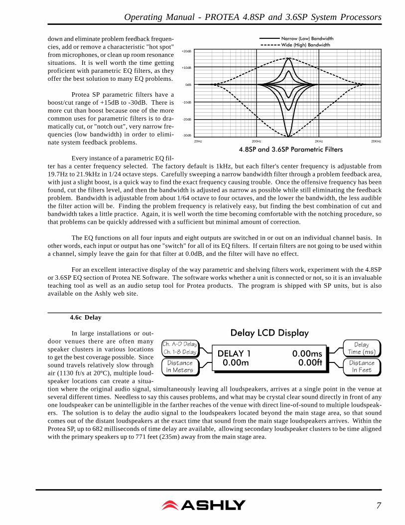
down and eliminate problem feedback frequen-cies, add or remove a characteristic "hot spot"from microphones, or clean up room resonancesituations. It is well worth the time gettingproficient with parametric EQ filters, as theyoffer the best solution to many EQ problems.
Protea SP parametric filters have aboost/cut range of +15dB to -30dB. There ismore cut than boost because one of the morecommon uses for parametric filters is to dra-matically cut, or "notch out", very narrow fre-quencies (low bandwidth) in order to elimi-nate system feedback problems.
Every instance of a parametric EQ fil-ter has a center frequency selected. The factory default is 1kHz, but each filter's center frequency is adjustable from19.7Hz to 21.9kHz in 1/24 octave steps. Carefully sweeping a narrow bandwidth filter through a problem feedback area,with just a slight boost, is a quick way to find the exact frequency causing trouble. Once the offensive frequency has beenfound, cut the filters level, and then the bandwidth is adjusted as narrow as possible while still eliminating the feedbackproblem. Bandwidth is adjustable from about 1/64 octave to four octaves, and the lower the bandwidth, the less audiblethe filter action will be. Finding the problem frequency is relatively easy, but finding the best combination of cut andbandwidth takes a little practice. Again, it is well worth the time becoming comfortable with the notching procedure, sothat problems can be quickly addressed with a sufficient but minimal amount of correction.
The EQ functions on all four inputs and eight outputs are switched in or out on an individual channel basis. Inother words, each input or output has one "switch" for all of its EQ filters. If certain filters are not going to be used withina channel, simply leave the gain for that filter at 0.0dB, and the filter will have no effect.
For an excellent interactive display of the way parametric and shelving filters work, experiment with the 4.8SPor 3.6SP EQ section of Protea NE Software. The software works whether a unit is connected or not, so it is an invaluableteaching tool as well as an audio setup tool for Protea products. The program is shipped with SP units, but is alsoavailable on the Ashly web site.
4.6c Delay
In large installations or out-door venues there are often manyspeaker clusters in various locationsto get the best coverage possible. Sincesound travels relatively slow throughair (1130 ft/s at 20ºC), multiple loud-speaker locations can create a situa-tion where the original audio signal, simultaneously leaving all loudspeakers, arrives at a single point in the venue atseveral different times. Needless to say this causes problems, and what may be crystal clear sound directly in front of anyone loudspeaker can be unintelligible in the farther reaches of the venue with direct line-of-sound to multiple loudspeak-ers. The solution is to delay the audio signal to the loudspeakers located beyond the main stage area, so that soundcomes out of the distant loudspeakers at the exact time that sound from the main stage loudspeakers arrives. Within theProtea SP, up to 682 milliseconds of time delay are available, allowing secondary loudspeaker clusters to be time alignedwith the primary speakers up to 771 feet (235m) away from the main stage area.
200Hz 2KHz 20KHz20Hz
0dB
-10dB
-20dB
+10dB
+20dB
-30dB
4.8SP and 3.6SP Parametric Filters
Wide (High) BandwidthNarrow (Low) Bandwidth
DELAY 1 0.00m
0.00ms0.00ft

Operating Manual - PROTEA 4.8SP and 3.6SP System Processors
8
Output channels have time delay as well. Output delay is best used to aligndiscrete drivers within a speaker cabinet or cluster, normally quite close together. Forexample, a typical three way speaker cluster would have low end, midrange, and highfrequency drivers all located near one another. The different drivers for each fre-quency band are not necessarily the same physi-cal depth with respect to the front of the loud-speaker cluster, so there exists the problem ofsame signals (at the crossover points) arrivingat the cluster "front" at different times, creatingundesirable wave interaction and frequencycancellation. The solution, again, is to slightlydelay the signal to the drivers closest to thecluster front. Using the location of the driverdiaphragm farthest back as a reference point,measure the distance to other drivers in the clus-ter, and set the output delay for each accord-ingly, with the driver diaphragm closest to thefront getting the longest delay and the driver atthe very back getting no output delay. Note:Although delay in the SP is adjusted only bytime, the corresponding distance in both feetand meters is always shown as well.
4.6d Crossover (Xover)
Crossover functions are avail-able only on the output channels.Every channel's crossover consists ofa high pass filter (HPF) and a low passfilter (LPF), along with the frequen-cies and filter types used. Eachoutput's crossover section is essentially a bandpass filter, making it necessary for the user to map out ahead of time whichoutputs will be used for the various frequency bands, and set the overlapping filter frequencies and types accordingly.Note: The HPF determines the lower frequency limit of the signal, while the LPF determines the upper frequency limit.
The frequency range for the high pass filter (HPF) is from 19.7Hz to 21.9kHz, with an option to turn the filter offat the low end of the frequency selection. The low pass filter (LPF) offers the same frequency range, with the "off" optionat the high end of the frequency selection.
There are 11 types of filters available in the crossover section, each suited to a specific preference or purpose.The slope of each filter type is defined by the first characters in the filter type, 12dB, 18dB, 24dB, or 48dB per octave.The steeper the slope, the more abruptly the "edges" of the pass band will drop off. There is no best filter slope for everyapplication, so experiment to see which one sounds most pleasing in a specific system. Ashly factory default presets useall 24dB/octave Linkwitz-Riley filters in the crossover section, but of course they can be changed to suit the applica-tion.
In addition to the frequency and slope, crossover filters can be selected as having Butterworth, Bessel, orLinkwitz-Riley response. These refer to the shape of a filter's slope at the cut-off frequency, affecting the way twoadjacent pass bands interact at the crossover point. 24db/octave Linkwitz-Riley filters produce a flat transition throughthe crossover region, assuming both overlapping filters are set to the same frequency, slope, and response type. 24dB/oct Linkwitz-Riley filters are the industry standard, the easiest to use, and the filter type recommended by Ashly. Otherfilter types are available, but may require polarity switching or other adjustments for proper results. The followingparagraphs offer a summary of the three filter types as used in 4.8SP and 3.6SP crossovers:
Same sound arrives attwo different times.
Fix by delaying secondary speakers 177mS.
Speaker onMain Stage
Secondary Speaker200 ft from Main Stage
Input (Long) Time DelayFor Remote Speakers
High - No Delay
Midrange Delay12 Inches = 0.9mS
Low Delay8 Inches = 0.6mS
Example: 12 Inches
Example: 8 Inches
Output (Short) Time DelayFor Driver Alignment
CROSSOVER 119.7Hz
HPF24dB-Lnkwtz
9
Operating Manual - PROTEA 4.8SP and 3.6SP System Processors
ButterworthButterworth filters individually are always -3dB at the displayed crossover frequency and are used because they
have a "maximally flat" passband and sharpest transition to the stopband. When a Butterworth HPF and LPF of the samecrossover frequency are summed, the combined response is always +3dB. With 12dB per octave Butterworth crossoverfilters, one of the outputs must be inverted or else the combined response will result in a large notch at the crossoverfrequency.
BesselThese filters, as implemented on the SP processors, are always -3dB at the displayed crossover frequency.
Bessel filters are used because they have a maximally flat group delay. Stated another way, Bessel filters have the mostlinear phase response. When a Bessel HPF and LPF of the same crossover frequency are summed, the combined responseis +3dB for 12dB/oct, 18dB/oct, and 48dB/oct Bessel filters, and -2dB for 24dB/oct Bessel filters. One of the outputsmust be inverted when using either 12dB/oct or 18dB/oct Bessel crossover filters or else the combined response willhave a large notch.
Linkwitz-RileyThe 12 dB/oct, 24dB/oct and 48dB/oct Linkwitz-Riley filters individually are always -6dB at the displayed
crossover frequency, however the 18dB/oct Linkwitz filters individually are always -3dB at the displayed crossoverfrequency. The reason for this is that Linkwitz-Riley filters are defined in terms of performance criterion on the summingof two adjacent crossover HPF and LPF filters, rather than defined in terms of the pole-zero characteristics of individualfilters. The 18dB/oct Linkwitz-Riley individually are 18dB/oct Butterworth filters in that they have Butterworth pole-zero characteristics and also satisfy the criterion for Linkwitz-Riley filters.
When a Linkwitz-Riley HPF and LPF of the same displayed crossover frequency are summed, the combinedresponse is always flat. With 12dB/oct Linkwitz-Riley crossover filters, one of the outputs must be inverted or else thecombined response will have a large notch at the crossover frequency.
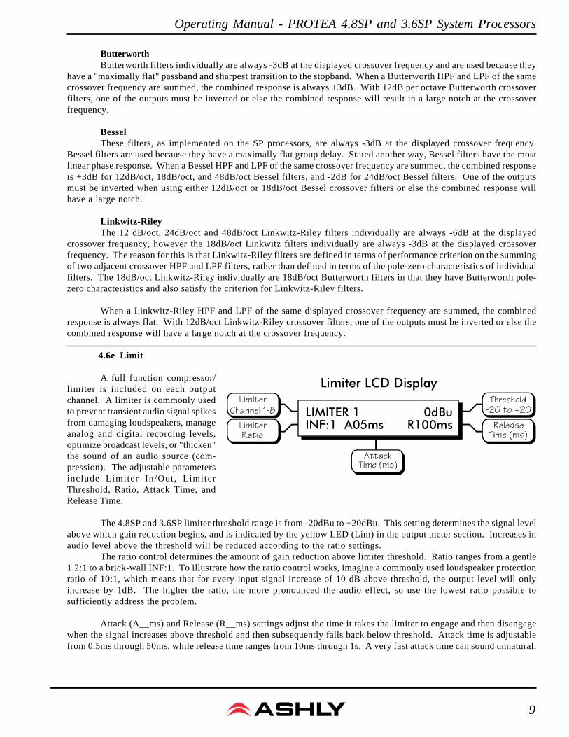
4.6e Limit
A full function compressor/limiter is included on each outputchannel. A limiter is commonly usedto prevent transient audio signal spikesfrom damaging loudspeakers, manageanalog and digital recording levels,optimize broadcast levels, or "thicken"the sound of an audio source (com-pression). The adjustable parametersinclude Limiter In/Out, LimiterThreshold, Ratio, Attack Time, andRelease Time.
The 4.8SP and 3.6SP limiter threshold range is from -20dBu to +20dBu. This setting determines the signal levelabove which gain reduction begins, and is indicated by the yellow LED (Lim) in the output meter section. Increases inaudio level above the threshold will be reduced according to the ratio settings.
The ratio control determines the amount of gain reduction above limiter threshold. Ratio ranges from a gentle1.2:1 to a brick-wall INF:1. To illustrate how the ratio control works, imagine a commonly used loudspeaker protectionratio of 10:1, which means that for every input signal increase of 10 dB above threshold, the output level will onlyincrease by 1dB. The higher the ratio, the more pronounced the audio effect, so use the lowest ratio possible tosufficiently address the problem.
Attack (A__ms) and Release (R__ms) settings adjust the time it takes the limiter to engage and then disengagewhen the signal increases above threshold and then subsequently falls back below threshold. Attack time is adjustablefrom 0.5ms through 50ms, while release time ranges from 10ms through 1s. A very fast attack time can sound unnatural,
LIMITER 1INF:1 A05ms
0dBuR100ms
Operating Manual - PROTEA 4.8SP and 3.6SP System Processors
10
while a very long attack time can miss some of the initial transient. Similarly, a very short release time can make the audiosound uneven, while a very long release time can create "pumping", or "breathing" characteristics depending on the kindof signal. Experiment to find the best solution for a given application.
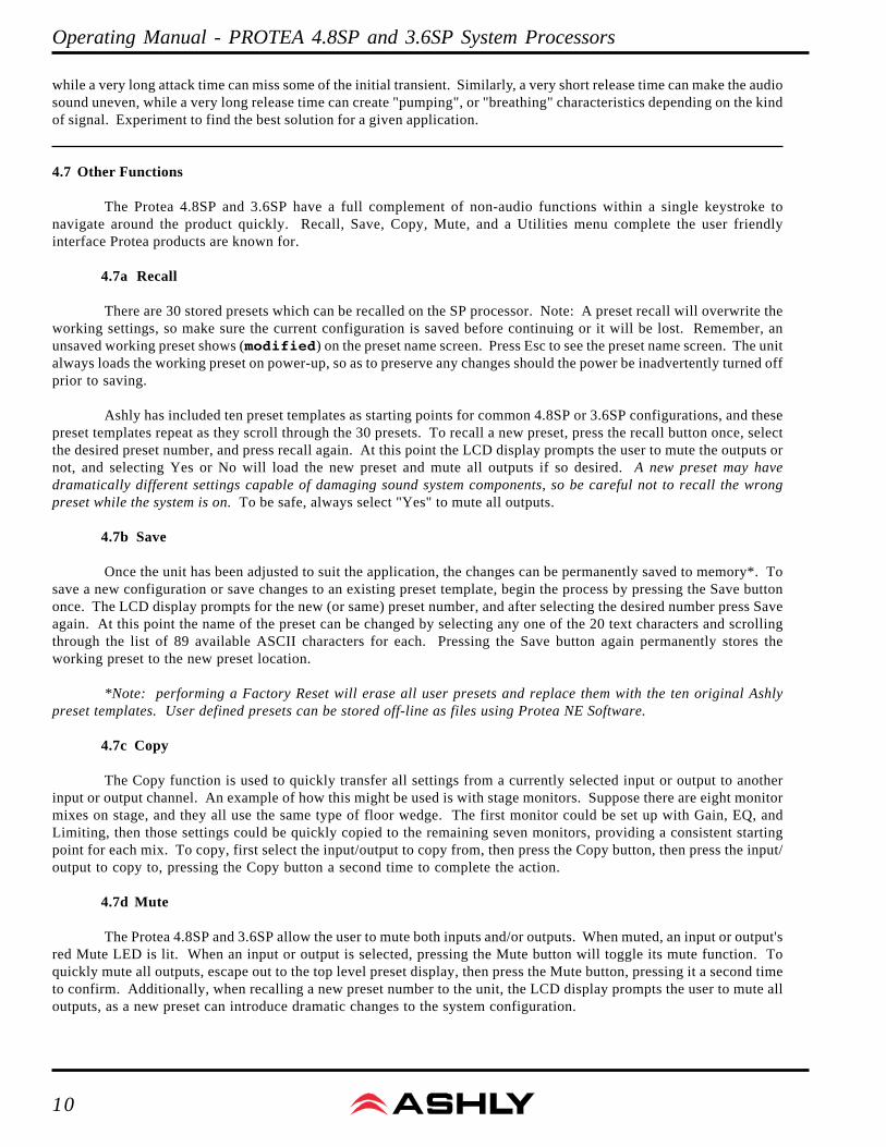
4.7 Other Functions
The Protea 4.8SP and 3.6SP have a full complement of non-audio functions within a single keystroke tonavigate around the product quickly. Recall, Save, Copy, Mute, and a Utilities menu complete the user friendlyinterface Protea products are known for.
4.7a Recall
There are 30 stored presets which can be recalled on the SP processor. Note: A preset recall will overwrite theworking settings, so make sure the current configuration is saved before continuing or it will be lost. Remember, anunsaved working preset shows (modified) on the preset name screen. Press Esc to see the preset name screen. The unitalways loads the working preset on power-up, so as to preserve any changes should the power be inadvertently turned offprior to saving.
Ashly has included ten preset templates as starting points for common 4.8SP or 3.6SP configurations, and thesepreset templates repeat as they scroll through the 30 presets. To recall a new preset, press the recall button once, selectthe desired preset number, and press recall again. At this point the LCD display prompts the user to mute the outputs ornot, and selecting Yes or No will load the new preset and mute all outputs if so desired. A new preset may havedramatically different settings capable of damaging sound system components, so be careful not to recall the wrongpreset while the system is on. To be safe, always select "Yes" to mute all outputs.
4.7b Save
Once the unit has been adjusted to suit the application, the changes can be permanently saved to memory*. Tosave a new configuration or save changes to an existing preset template, begin the process by pressing the Save buttononce. The LCD display prompts for the new (or same) preset number, and after selecting the desired number press Saveagain. At this point the name of the preset can be changed by selecting any one of the 20 text characters and scrollingthrough the list of 89 available ASCII characters for each. Pressing the Save button again permanently stores theworking preset to the new preset location.
*Note: performing a Factory Reset will erase all user presets and replace them with the ten original Ashlypreset templates. User defined presets can be stored off-line as files using Protea NE Software.
4.7c Copy
The Copy function is used to quickly transfer all settings from a currently selected input or output to anotherinput or output channel. An example of how this might be used is with stage monitors. Suppose there are eight monitormixes on stage, and they all use the same type of floor wedge. The first monitor could be set up with Gain, EQ, andLimiting, then those settings could be quickly copied to the remaining seven monitors, providing a consistent startingpoint for each mix. To copy, first select the input/output to copy from, then press the Copy button, then press the input/output to copy to, pressing the Copy button a second time to complete the action.
4.7d Mute
The Protea 4.8SP and 3.6SP allow the user to mute both inputs and/or outputs. When muted, an input or output'sred Mute LED is lit. When an input or output is selected, pressing the Mute button will toggle its mute function. Toquickly mute all outputs, escape out to the top level preset display, then press the Mute button, pressing it a second timeto confirm. Additionally, when recalling a new preset number to the unit, the LCD display prompts the user to mute alloutputs, as a new preset can introduce dramatic changes to the system configuration.
11
Operating Manual - PROTEA 4.8SP and 3.6SP System Processors
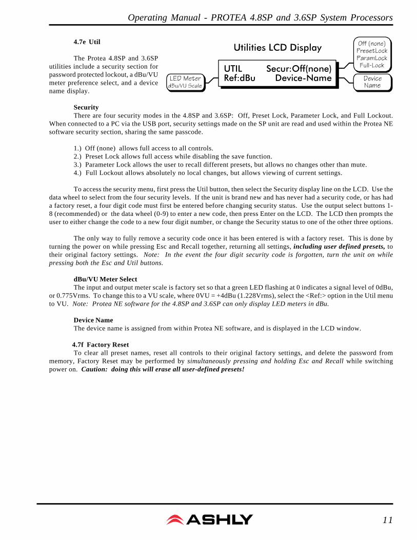
4.7e Util
The Protea 4.8SP and 3.6SPutilities include a security section forpassword protected lockout, a dBu/VUmeter preference select, and a devicename display.
SecurityThere are four security modes in the 4.8SP and 3.6SP: Off, Preset Lock, Parameter Lock, and Full Lockout.
When connected to a PC via the USB port, security settings made on the SP unit are read and used within the Protea NEsoftware security section, sharing the same passcode.
1.) Off (none) allows full access to all controls.2.) Preset Lock allows full access while disabling the save function.3.) Parameter Lock allows the user to recall different presets, but allows no changes other than mute.4.) Full Lockout allows absolutely no local changes, but allows viewing of current settings.
To access the security menu, first press the Util button, then select the Security display line on the LCD. Use thedata wheel to select from the four security levels. If the unit is brand new and has never had a security code, or has hada factory reset, a four digit code must first be entered before changing security status. Use the output select buttons 1-8 (recommended) or the data wheel (0-9) to enter a new code, then press Enter on the LCD. The LCD then prompts theuser to either change the code to a new four digit number, or change the Security status to one of the other three options.
The only way to fully remove a security code once it has been entered is with a factory reset. This is done byturning the power on while pressing Esc and Recall together, returning all settings, including user defined presets, totheir original factory settings. Note: In the event the four digit security code is forgotten, turn the unit on whilepressing both the Esc and Util buttons.
dBu/VU Meter SelectThe input and output meter scale is factory set so that a green LED flashing at 0 indicates a signal level of 0dBu,
or 0.775Vrms. To change this to a VU scale, where 0VU = +4dBu (1.228Vrms), select the <Ref:> option in the Util menuto VU. Note: Protea NE software for the 4.8SP and 3.6SP can only display LED meters in dBu.
Device NameThe device name is assigned from within Protea NE software, and is displayed in the LCD window.
4.7f Factory ResetTo clear all preset names, reset all controls to their original factory settings, and delete the password from
memory, Factory Reset may be performed by simultaneously pressing and holding Esc and Recall while switchingpower on. Caution: doing this will erase all user-defined presets!
UTILRef:dBu
Secur:Off(none)Device-Name

Operating Manual - PROTEA 4.8SP and 3.6SP System Processors
12
5. INTERCONNECT FEATURES
5.1 Audio Connections
All Protea audio connections use three pin XLR jacks, with pin 2 (+), pin 3 (-), and pin 1(G). Inputs and outputsare electronically precision balanced. If an unbalanced signal is fed to an input, the signal should be on the (+)connection (pin 2) and pin 3 must be tied to ground, or significant signal loss will result. In other words, never float pin2 or pin 3. It is strongly recommended that balanced signals be used whenever possible.
A Note About Input Signal Levels:There are no analog gain trim adjustments on the Protea SP unit, therefore all the processing (including gain)
is done in the digital domain. As a consequence of this design philosophy, it is important to feed the Protea processorwith the proper nominal signal level to achieve good signal to noise performance as well as headroom before clipping.This unit is designed to clip at signal levels above +20dBu = 7.75Vrms which places the noise floor lower than -90dBu.The optimum input signal level which should be fed into the Protea processor is 0dBu = .775Vrms. This input level willallow 20dB of headroom while giving a nominal signal that is >90dB above the noise floor.
5.2 USB Connection
There are two USB ports on the SP unit, one on the front and one on the back panel. They bothserve the same function, but a front panel USB connection will always override the back panel USB portif both are being used simultaneously. A six foot USB-A to USB-B cable is provided with every ProteaSP unit to connect to a computer running Ashly Protea NE software.
5.3 RS-232 Data Connections
Several third party controllers use RS-232 for control of other devices which may include theProtea SP processors. For detailed information regarding the implementation of RS-232 control, contactthe Ashly service department. Note: Protea NE software will not work with a 4.8SP or 3.6SP processorusing RS-232. The computer connection must use a USB port.
6. PROTEA NE SOFTWARE
Loading the softwareAshly Protea NE software is included on a CD with each unit. Check the Ashly web site at www.ashly.com to
verify that you are installing the latest software release. Autorun will launch the application<ProteaSystemSoftwareNE>to install the Protea software.
Connect the SP processorThe control connection is made using a standard USB-A to USB-B cable, provided by Ashly with each unit.
Identify the processor in softwareOnce the software is loaded to the computer and the data connection has been made to the 4.8SP or 3.6SP, all
installed NE software compatible Ashly products will be automatically detected and shown in the active device listingon the left side of the Protea NE software startup canvas. Note: In the event of multiple processors of the same model onthe network, the user can find a single physical unit by right clicking over the unit’s name in the drop down menu, andthen click <Identify>, which will flash the Com LED on that unit’s face panel for two seconds.
The software scans for active devices on power-up, but the user can manually scan at any time as well with <ScanFor Devices> at the bottom of the network device listing. All Ashly devices continuously broadcast their availability tothe software. All currently connected and active products are highlighted in green, while units which may be or have
13
Operating Manual - PROTEA 4.8SP and 3.6SP System Processors
been formerly installed but are currently off-line or unavailable show up in red. Individual products can be dragged ontothe project canvas to simulate physical rack installation groups, but editing each product can be done from either theproduct list or the image on the canvas.
The NE software project canvasThe project canvas is used to visually represent and control a fixed physical sound system installation, and can
display any of the Ashly processors, amplifiers, and remotes used in that system. The user can also place an assortmentof isolated control objects such as level faders, single LEDs, meter bars, etc, and map them to specific product functionswithin that project. Once a control object is placed, right click on it to bring up its properties. Additionally, lines,rectangles, text, and even image files can be added to create a custom virtual control screen along with the Ashlyproducts and individual control objects. To see all available canvas tools, right click anywhere over open canvas.Checking <Design Mode> allows placed objects to be moved around, while unchecking <Design Mode> locks objectsin place
MetersInputs and outputs each have real-time virtual meter displays, shown in dBu only. Output compressor/limiters
have meter displays shown in dB.
Presets OptionsThe 4.8SP or 3.6SP will store up to 30 total presets. A preset file takes a “snapshot” of all current settings and stores
complete control data for all channels and all audio functions. In addition to pressing the Save button on the face panel,individual presets can be saved to the processor by using <Preset Options/Save Preset To Protea>, or saved to a PC using<Preset Options/Save To Disk>. Preset files for Ashly SP products use the extension (*.pne).
In addition to the face panel preset recall button, a preset can be recalled in software from either a computer or fromthe processor’s internal memory. Caution: A new preset may have dramatically different settings capable of damagingsound system components, so be careful not to recall the wrong preset while the system is on.
The Protea 4.8SP and 3.6SP are similar to the older Ashly Protea 4.24C and 3.24CL models respectively. An existingpreset file from the older *.pcc format can be loaded onto the new SP unit using <Preset Options/Load 4.24C Preset FromDisk>.
SecurityThe 4.8SP and 3.6SP processors have front panel security options within the utilities menu. Additionally, Protea NE
software offers independent management of the front panel security as well as software security. The password will be thesame in software as it is on the physical unit.
Operating Manual - PROTEA 4.8SP and 3.6SP System Processors
14
7. TROUBLESHOOTING
7.1 - Audio Troubleshooting Tips
No power - Is the detachable AC cord fully plugged in? Is the rear panel power switch on?
Controls don't work - check the Security Level. If set to Full Lockout, then Protea unit is "view only". Changesecurity settings in Util menu or software.
No sound - Check to see if the input or output is muted. Is the input or output Gain turned down? Check theselected audio source(s) for each output, making sure there is signal applied to the designated input(s). If the crossoveris used, make sure the high pass filter (HPF) is set to a lower frequency than the low pass filter (LPF).
Clip light stays on - Is the input signal level too high? Check to see that the nominal input level is 0dBu, allowing20dB of input headroom. Are input or output gain settings too high? Check to see if an EQ filter has too much boost.
Distorted sound but no Clip LED- Check individual EQ filters to see if there is excessive boost.
Muffled sound - If expecting full range audio on an output, make sure the crossover settings are not inadvertentlyset so as to limit the pass band.
Excessive Noise - An input signal level or an input gain setting that is too low could require the loss to be madeup for at the output gain stage, producing more noise than a properly set up gain structure. Do not use the DSP processorsection for dramatic increases in level, but rather optimize the signal source for a nominal 0dBu output.
Forgot the password - See section 4.7e
8. SPECIFICATIONS
Input . . . . . . . . . . . . . . . . . . . . . . . . . . . . . . Active Balanced, 18KΩMax. Input Level . . . . . . . . . . . . . . . . . . . . +20dBuInput Gain Range . . . . . . . . . . . . . . . . . . . -40dB to +12dB
Output . . . . . . . . . . . . . . . . . . . . . . . . . . . . Active Balanced, 112ΩMax. Output Level . . . . . . . . . . . . . . . . . . +20dBuOutput Gain Range . . . . . . . . . . . . . . . . . . -40dB to +12dB
EQEQ Filter Types . . . . . . . . . . . . . . . . . . . . . 1st or 2nd Order High or Low Shelf, ParametricShelving Filter Boost/Cut Range . . . . . . ±15dBShelving Filter Frequency Range . . . . . . Low Shelf 19.7Hz to 2kHz, High Shelf 3.8kHz to 21.9kHzParametric Filter Boost/Cut Range . . . . +15dB/-30dBParametric Filter Frequency Range . . . 19.7Hz to 21.9kHz, 1/24 Octave StepsParametric Filter Bandwidth . . . . . . . . . Four Octaves to 1/64 Octave
Input and Output Delay . . . . . . . . . . . . . . 0-682 milliseconds
CrossoverHPF and LPF Frequency Range . . . . . . . 19.7Hz to 21.9kHz, OffAvailable Filter Types . . . . . . . . . . . . . . . 12dB/Oct Butterworth, 12dB/Oct Bessel, 12dB/Oct Linkwitz-Riley 18dB/Oct Bessel, 18dB/Oct Linkwitz-Riley 24dB/Oct Butterworth, 24dB/Oct Bessel, 24dB/Oct Linkwitz-Riley 48dB/Oct Butterworth, 48dB/Oct Bessel, 48dB/Oct Linkwitz-Riley
15
Operating Manual - PROTEA 4.8SP and 3.6SP System Processors
LimiterThreshold Range . . . . . . . . . . . . . . . . . . . -20dBu to +20 dBuRatio Range . . . . . . . . . . . . . . . . . . . . . . . . 1.2:1 to INF:1Attack Time Range . . . . . . . . . . . . . . . . . 0.5ms to 50msRelease Time Range . . . . . . . . . . . . . . . . 10ms to 1 Second
Frequency Response . . . . . . . . . . . . . . . . 20Hz to 20KHz, ±0.25dBTHD . . . . . . . . . . . . . . . . . . . . . . . . . . . . . . <0.01% @ 1KHz, +20dBuDynamic Range . . . . . . . . . . . . . . . . . . . . >110dB 20Hz - 20KHz unweightedAudio Sampling Rate . . . . . . . . . . . . . . . 48KHzPropagation Delay . . . . . . . . . . . . . . . . . 1.46mSSignal LEDs & Clip . . . . . . . . . . . . . . . . Inputs: -20/Mute, -10, 0, +10, Clip (dBu or VU) Outputs: -20/Mute, -10, 0, Limit Threshold, Clip (dBu or VU)AC Requirements . . . . . . . . . . . . . . . . . . . Universal Power Supply, 100-240VAC, 50/60Hz, 20W maxEnvironmental . . . . . . . . . . . . . . . . . . . . . 40°F - 120°F (4°C-49°C) Non-condensingWeight . . . . . . . . . . . . . . . . . . . . . . . . . . . . 9 LbsDimensions . . . . . . . . . . . . . . . . . . . . . . . . 19.0” L x 1.75” H x 8.5” D (48.3 cm x 8.9 cm x 21.6 cm)
9. ASHLY AUDIO INC Limited Warranty (USA ONLY)(Other countries please contact your respective distributor or dealer)
For units purchased in the USA, warranty service for this unit shall be provided by ASHLY AUDIO, INC. inaccordance with the following warranty statement:
ASHLY AUDIO, INC. warrants to the owner of this product that it will be free from defects in workmanship andmaterials for a period of FIVE years from the original date of purchase. ASHLY AUDIO INC. will without charge, repair orreplace at its discretion any defective product or component parts upon prepaid delivery of the product to the ASHLYAUDIO, INC. factory service department, accompanied with a proof of original date of purchase in the form of a valid salesreceipt. This warranty gives you specific legal rights, and you may also have other rights, which vary from state to state.
EXCLUSIONS: This warranty does not apply in the event of misuse, neglect or as a result of unauthorizedalterations or repairs made to the product. This warranty is void if the serial number is altered, defaced, or removed. ASHLYAUDIO reserves the right to make changes in design, or make additions to, or improvements upon this product, withoutany obligation to install the same on products previously manufactured.
Any implied warranties which may arise under the operation of state law shall be effective only for FIVE yearsfrom the original date of purchase of the product. ASHLY AUDIO, INC. shall be obligated to only correct defects in theproduct itself. ASHLY AUDIO, INC. is not liable for any damage or injury which may result from or be incidental to or aconsequence of such defect. Some states do not allow limitations on how long an implied warranty lasts, or the exclusion,or limitation of incidental or consequential damages, so the above limitations or exclusions may not apply to you.
OBTAINING WARRANTY SERVICE:
For warranty service in the United States, please follow this procedure:
1) Return the product to ASHLY AUDIO, INC, freight prepaid, with a written statement describing the defect andapplication that the product is used in. ASHLY AUDIO, INC. will examine the product and perform any necessary service,including replacement of defective parts, at no further cost to you.
2) Ship your product to:
Ashly Audio Inc.Attn: Service Department847 Holt RoadWebster, NY 14580-9103
Operating Manual - PROTEA 4.8SP and 3.6SP System Processors
ASHLY AUDIO INC. 847 Holt Road Webster, NY 14580-9103Phone: (585) 872-0010 Fax: (585) 872-0739
Toll Free (800) 828-6308 www.ashly.comCopyright 2011 by Ashly Audio Corporation. All rights reserved worldwide.
Protea 4.8SP and 3.6SP R2 0111 Printed in USA
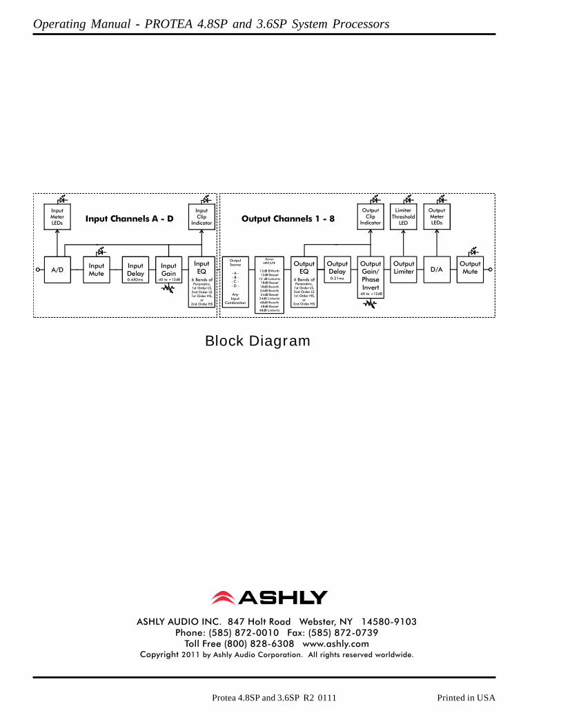
A/D
A/DInputMute
InputEQ
InputMeterLEDs Input Channels A - D
-40 to +12dB
InputGain
6 Bands ofParametric,
1st Order LS,2nd Order LS1st Order HS,
or2nd Order HS
InputClip
Indicator
InputDelay0-682ms
OutputEQ
4 Bands ofParametric,
1st Order LS,2nd Order LS1st Order HS,
or2nd Order HS
-40 to +12dB
OutputClip
Indicator
0-21ms
OutputSource
- A -- B -- C -- D -
AnyInput
Combination
XoverHPF/LPF
12dB BWorth12dB Bessel
12 dB Linkwitz18dB Bessel18dB Bworth24dB Bworth24dB Bessel
24dB Linkwitz48dB Bworth48dB Bessel
48dB Linkwitz
OutputDelay
OutputGain/PhaseInvert
OutputLimiter
OutputMute
LimiterThreshold
LED
OutputMeterLEDs
D/A
Output Channels 1 - 8
Block Diagram