46494766 Quidway s6502 Ethernet Switch Installation Manual 1
120
Huawei Technologies Proprietary HUAWEI Quidway S6502 Ethernet Switch Installation Manual Release 3000 Series
-
Upload
andrecastro46 -
Category
Documents
-
view
291 -
download
3
description
Huawei s6502
Transcript of 46494766 Quidway s6502 Ethernet Switch Installation Manual 1

Huawei Technologies Proprietary
HUAWEI
Quidway S6502 Ethernet Switch Installation Manual
Release 3000 Series
Huawei Technologies Proprietary
Quidway S6502 Ethernet Switch
Installation Manual
Manual Version T2-080476-20050610-C-1.00
Product Version Release 3000 Series
BOM 3104A076
Huawei Technologies Co., Ltd. provides customers with comprehensive technical support and service. If you purchase the products from the sales agent of Huawei Technologies Co., Ltd., please contact our sales agent. If you purchase the products from Huawei Technologies Co., Ltd. directly, Please feel free to contact our local office, customer care center or company headquarters.
Huawei Technologies Co., Ltd.
Address: Administration Building, Huawei Technologies Co., Ltd.,
Bantian, Longgang District, Shenzhen, P. R. China
Postal Code: 518129
Website: http://www.huawei.com

Huawei Technologies Proprietary
Copyright © 2005 Huawei Technologies Co., Ltd.
All Rights Reserved
No part of this manual may be reproduced or transmitted in any form or by any means without prior written consent of Huawei Technologies Co., Ltd.
Trademarks
, HUAWEI, C&C08, EAST8000, HONET, , ViewPoint, INtess, ETS, DMC,
TELLIN, InfoLink, Netkey, Quidway, SYNLOCK, Radium, M900/M1800, TELESIGHT, Quidview, Musa, Airbridge, Tellwin, Inmedia, VRP, DOPRA, iTELLIN, HUAWEI OptiX, C&C08 iNET, NETENGINE, OptiX, iSite, U-SYS, iMUSE, OpenEye, Lansway, SmartAX, infoX, and TopEng are trademarks of Huawei Technologies Co., Ltd.
All other trademarks and trade names mentioned in this manual are the property of their respective holders.
Notice
The information in this manual is subject to change without notice. Every effort has been made in the preparation of this manual to ensure accuracy of the contents, but all statements, information, and recommendations in this manual do not constitute the warranty of any kind, express or implied.

Huawei Technologies Proprietary
About This Manual
Release Notes
The corresponding product version of this manual is Release 3000 Series.
Related Manuals
The following manuals provide more information about the Quidway S6502 Ethernet Switch.
Manual Content
Quidway S6502 Ethernet Switch Installation Manual
It provides information for the system installation.
Quidway S6500 Series Ethernet Switches Operation Manual
It is used for assisting the users in data configurations and typical applications.
Quidway S6500 Series Ethernet Switches Command Manual
It is used for assisting the users in using various commands.
Organization
Quidway S6502 Ethernet Switch Installation Manual mainly introduces the hardware features, installation, configuration and maintenance of S6502 Ethernet Switch. To avoid any possible device damage and personal injury before the installation and during the installation, please read the manual carefully. The manual consists of the following chapters.
Chapter 1 Product Overview The chapter introduces the characteristics of S6502 Ethernet Switch according to the forwarding engines.
Chapter 2 Line Processing Unit The chapter introduces LPUs of S6502 Ethernet Switch.
Chapter 3 Installation Preparation The chapter introduces the installation preparation and precaution of S6502 Ethernet Switch.
Chapter 4 Hardware Installation The chapter introduces the booting process of S6502 Ethernet Switch, including the setup of mainframe, cards and cables.

Huawei Technologies Proprietary
Chapter 5 System Debugging The chapter introduces the system debugging.
Chapter 6 Switch Monitoring and Maintenance The chapter introduces the monitoring and maintenance of S6502 Ethernet Switch.
Appendix A Lightning Protection of the Switch The appendix introduces lightning protection of S6502 Ethernet Switch.
Intended Audience
The manual is intended for the following readers:
Network engineers Network administrators Customers who are familiar with network fundamentals
Conventions
The manual uses the following conventions:
I. General conventions
Convention Description
Arial Normal paragraphs are in Arial.
Boldface Headings are in Boldface.
Courier New Terminal Display is in Courier New.
II. GUI conventions
Convention Description
< > Button names are inside angle brackets. For example, click the <OK> button.
[ ] Window names, menu items, data table and field names are inside square brackets. For example, pop up the [New User] window.
/ Multi-level menus are separated by forward slashes. For example, [File/Create/Folder].

Huawei Technologies Proprietary
III. Keyboard operation
Format Description
<Key> Press the key with the key name inside angle brackets. For example, <Enter>, <Tab>, <Backspace>, or <A>.
<Key1+Key2> Press the keys concurrently. For example, <Ctrl+Alt+A> means the three keys should be pressed concurrently.
<Key1, Key2> Press the keys in turn. For example, <Alt, A> means the two keys should be pressed in turn.
IV. Mouse operation
Action Description
Select Press and hold the primary mouse button (left mouse button by default).
Click Select and release the primary mouse button without moving the pointer.
Double-Click Press the primary mouse button twice continuously and quickly without moving the pointer.
Drag Press and hold the primary mouse button and move the pointer to a certain position.
V. Symbols
Eye-catching symbols are also used in the manual to highlight the points worthy of special attention during the operation. They are defined as follows:
Caution, Warning, Danger: Means reader be extremely careful during the
operation.
Note, Comment, Tip, Knowhow, Thought: Means a complementary description.
Environmental Protection
This product has been designed to comply with the requirements on environmental protection. For the proper storage, use and disposal of this product, national laws and regulations must be observed.

Installation Manual Quidway S6502 Ethernet Switch Table of Contents
Huawei Technologies Proprietary
i
Table of Contents
Chapter 1 Product Overview ........................................................................................................ 1-1 1.1 General Information ........................................................................................................... 1-1
1.1.1 Preface .................................................................................................................... 1-1 1.1.2 Switching Engine..................................................................................................... 1-1
1.2 SRPU specifications .......................................................................................................... 1-2 1.3 LS81P12TE........................................................................................................................ 1-3
1.3.1 Specifications .......................................................................................................... 1-3 1.3.2 Panel and LEDs ...................................................................................................... 1-4 1.3.3 Cable ....................................................................................................................... 1-5
1.4 LS81T12PE........................................................................................................................ 1-6 1.4.1 Specifications .......................................................................................................... 1-6 1.4.2 Panel and LEDs ...................................................................................................... 1-7 1.4.3 Port Cable ............................................................................................................... 1-8
1.5 Relationship between Switching Engines and Cards ........................................................ 1-8 1.6 Overall Hardware Layout of S6502.................................................................................... 1-8
1.6.1 Chassis.................................................................................................................... 1-8 1.6.2 Backplane.............................................................................................................. 1-12 1.6.3 Power Supplies ..................................................................................................... 1-12 1.6.4 External PoE Power Supply .................................................................................. 1-14 1.6.5 Fan Tray ................................................................................................................ 1-14
1.7 Technical Specifications .................................................................................................. 1-15
Chapter 2 Line Processing Unit ................................................................................................... 2-1 2.1 Brief Introduction to LPU.................................................................................................... 2-1 2.2 LS81FT48A-48-port 10Base-T/100Base-TX Fast Ethernet Card...................................... 2-1
2.2.1 Introduction to Card................................................................................................. 2-1 2.2.2 Panel and LEDs ...................................................................................................... 2-2 2.2.3 Matching Cable ....................................................................................................... 2-2
2.3 LS81FT48E-48-port 10/100Base-T Fast Ethernet Card.................................................... 2-3 2.3.1 Introduction to Card................................................................................................. 2-3 2.3.2 Panel and LEDs ...................................................................................................... 2-4 2.3.3 Matching Cable ....................................................................................................... 2-4
2.4 LS81FT48F-PoE-Supported 48-port 10/100Base-T Fast Ethernet Card .......................... 2-5 2.4.1 Introduction to Card................................................................................................. 2-5 2.4.2 Panel and LEDs ...................................................................................................... 2-6 2.4.3 Matching Cable ....................................................................................................... 2-6
2.5 LS81FM24A/LS81FS24A-24-port 100Base-FX MMF/SMF Fast Ethernet Card ............... 2-7 2.5.1 Introduction to Card................................................................................................. 2-7

Installation Manual Quidway S6502 Ethernet Switch Table of Contents
Huawei Technologies Proprietary
ii
2.5.2 Panel and LEDs ...................................................................................................... 2-8 2.5.3 Matching Cable ....................................................................................................... 2-8
2.6 LS81FP48-48-port 100Base-FX(SFP) Ethernet Card ....................................................... 2-9 2.6.1 Introduction.............................................................................................................. 2-9 2.6.2 Panel and LEDs .................................................................................................... 2-10 2.6.3 Matching Cable ..................................................................................................... 2-10
2.7 LS81GT8UA-8-port 10/100/1000Base-T Ethernet Card.................................................. 2-11 2.7.1 Introduction to Card............................................................................................... 2-11 2.7.2 Panel and LEDs .................................................................................................... 2-12 2.7.3 Matching Cable ..................................................................................................... 2-12
2.8 LS81GT8UE-8-port 10/100/1000Base-T Ethernet Card.................................................. 2-13 2.8.1 Introduction to Card............................................................................................... 2-13 2.8.2 Panel and LEDs .................................................................................................... 2-14 2.8.3 Matching Cable ..................................................................................................... 2-14
2.9 LS82GT20-20-port 10/100/1000Base-T Ethernet Card................................................... 2-15 2.9.1 Introduction to Card............................................................................................... 2-15 2.9.2 Panel and LEDs .................................................................................................... 2-16 2.9.3 Matching Cable ..................................................................................................... 2-16
2.10 LS82GT20A-20-port 10/100/1000Base-T Ethernet Card .............................................. 2-16 2.10.1 Introduction to Card............................................................................................. 2-16 2.10.2 Panel and LEDs .................................................................................................. 2-17 2.10.3 Matching Cable ................................................................................................... 2-18
2.11 LS81GT48-48-port 10/100/1000Base-T Ethernet Card................................................. 2-18 2.11.1 Introduction to Card............................................................................................. 2-18 2.11.2 Panel and LEDs .................................................................................................. 2-19 2.11.3 Matching Cable ................................................................................................... 2-19
2.12 LS81GT48A-PoE-Supported 48-port 10/100/1000Base-T Ethernet Card .................... 2-20 2.12.1 Introduction to Card............................................................................................. 2-20 2.12.2 Panel and LEDs .................................................................................................. 2-21 2.12.3 Matching Cable ................................................................................................... 2-21
2.13 LS81T12P-12-port 10/100/1000Base-T + 4-port 1000Base-X (SFP) Ethernet Card.... 2-22 2.13.1 Introduction to Card............................................................................................. 2-22 2.13.2 Panel and LEDs .................................................................................................. 2-23 2.13.3 Matching Cable ................................................................................................... 2-24
2.14 LS81P12T-12-port 1000Base-X (SFP) + 4-port 10/100/1000Base-T Ethernet Card.... 2-25 2.14.1 Introduction to Card............................................................................................. 2-25 2.14.2 Panel and LEDs .................................................................................................. 2-26 2.14.3 Matching Cable ................................................................................................... 2-27
2.15 LS81GB8UA-8-port 1000Base-X (GBIC) Ethernet Card............................................... 2-27 2.15.1 Introduction to Card............................................................................................. 2-27 2.15.2 Panel and LEDs .................................................................................................. 2-28 2.15.3 Matching Cable ................................................................................................... 2-29

Installation Manual Quidway S6502 Ethernet Switch Table of Contents
Huawei Technologies Proprietary
iii
2.16 LS81GP8UB-8-port 1000Base-X (SFP) Ethernet Card................................................. 2-29 2.16.1 Introduction to Card............................................................................................. 2-29 2.16.2 Panel and LEDs .................................................................................................. 2-30 2.16.3 Matching Cable ................................................................................................... 2-31
2.17 LS82GP20-20-port 1000Base-X (SFP) Ethernet Card.................................................. 2-31 2.17.1 Introduction to Card............................................................................................. 2-31 2.17.2 Panel and LEDs .................................................................................................. 2-32 2.17.3 Matching Cable ................................................................................................... 2-32
2.18 LS82GP20A-20-port 1000Base-X (SFP) Ethernet Card ............................................... 2-33 2.18.1 Introduction to Card............................................................................................. 2-33 2.18.2 Panel and LEDs .................................................................................................. 2-34 2.18.3 Matching Cable ................................................................................................... 2-34
2.19 LS81TGX1B-1-port 10GBASE-R-XENPAK Ethernet Card ........................................... 2-34 2.19.1 Introduction to Card............................................................................................. 2-34 2.19.2 Panel and LEDs .................................................................................................. 2-35 2.19.3 Matching Cable ................................................................................................... 2-36
2.20 LS81TGX1C-1-port 10GBASE-R-XENPAK Ethernet Card ........................................... 2-36 2.20.1 Introduction to Card............................................................................................. 2-36 2.20.2 Panel and LEDs .................................................................................................. 2-37 2.20.3 Matching Cable ................................................................................................... 2-37
Chapter 3 Installation Preparations............................................................................................. 3-1 3.1 Safety Information.............................................................................................................. 3-1
3.1.1 General Recommendations .................................................................................... 3-1 3.1.2 Electricity ................................................................................................................. 3-1 3.1.3 Moving..................................................................................................................... 3-1 3.1.4 Wearing an ESD Wrist Strap................................................................................... 3-2 3.1.5 Laser ....................................................................................................................... 3-3
3.2 Examining Installation Site................................................................................................. 3-3 3.2.1 Temperature/Humidity Requirements ..................................................................... 3-3 3.2.2 Cleanness Requirements........................................................................................ 3-3 3.2.3 Anti-static Requirements ......................................................................................... 3-4 3.2.4 Grounding Requirements ........................................................................................ 3-5 3.2.5 Power Supply Requirements................................................................................... 3-5
3.3 Installation Planning........................................................................................................... 3-5 3.3.1 Space Requirement ................................................................................................ 3-5 3.3.2 Rack-Mounting Requirements................................................................................. 3-5
3.4 Installation Tools ................................................................................................................ 3-6
Chapter 4 Hardware Installation .................................................................................................. 4-1 4.1 Confirm the Installation Preparation .................................................................................. 4-1 4.2 Installation Flowchart ......................................................................................................... 4-1 4.3 Mount the Switch in 19-Inch Standard Rack ..................................................................... 4-2 4.4 Mount the Switch on the Tabletop ..................................................................................... 4-2

Installation Manual Quidway S6502 Ethernet Switch Table of Contents
Huawei Technologies Proprietary
iv
4.5 Connect Ground Wire and Power Cord............................................................................. 4-2 4.5.1 Connect Ground Wire ............................................................................................. 4-2 4.5.2 Connect AC Power Cord......................................................................................... 4-5
4.6 Install Cabling Rack ........................................................................................................... 4-6 4.7 Install Switch Boards ......................................................................................................... 4-6 4.8 Connect Port Cables.......................................................................................................... 4-7
4.8.1 Connect Console Cable .......................................................................................... 4-7 4.8.2 Connect Category-5 Cables.................................................................................... 4-8 4.8.3 Connect Optical Fibers............................................................................................ 4-9
4.9 Recommendations on Cabling......................................................................................... 4-11 4.9.1 For Table-Mounting............................................................................................... 4-11 4.9.2 Rack-Mounted Switch ........................................................................................... 4-11
4.10 Cable Binding................................................................................................................. 4-11 4.10.1 Use of Labels ...................................................................................................... 4-11 4.10.2 Precautions for Binding Cables........................................................................... 4-11
4.11 Check after Installation .................................................................................................. 4-14
Chapter 5 System Debugging ...................................................................................................... 5-1 5.1 Setting up Configuration Environment............................................................................... 5-1
5.1.1 Setting up Configuration Environment .................................................................... 5-1 5.1.2 Connecting Console Cable ..................................................................................... 5-1 5.1.3 Setting Terminal Parameters .................................................................................. 5-1
5.2 Powering on and Booting................................................................................................... 5-5 5.2.1 Checking before Power on...................................................................................... 5-5 5.2.2 Powering on the Switch........................................................................................... 5-5 5.2.3 Checking after Power on (Recommended)............................................................. 5-5 5.2.4 Booting Interface ..................................................................................................... 5-5
Chapter 6 Switch Monitoring and Maintenance ......................................................................... 6-1 6.1 Switch Monitoring............................................................................................................... 6-1
6.1.1 Configuration System Troubleshooting................................................................... 6-1 6.1.2 Power Troubleshooting ........................................................................................... 6-2 6.1.3 Fan Troubleshooting ............................................................................................... 6-2 6.1.4 Cards Troubleshooting............................................................................................ 6-2
6.2 Hardware Maintenance...................................................................................................... 6-3 6.2.1 Power Module Replacement ................................................................................... 6-3 6.2.2 Service Card Replacement ..................................................................................... 6-4 6.2.3 Fan Frame Replacement ........................................................................................ 6-5
6.3 BOOTROM and Host Software Loading............................................................................ 6-6 6.3.1 Introduction to Loading Approaches ....................................................................... 6-6 6.3.2 Loading Software Locally via Boot Menu................................................................ 6-7 6.3.3 Loading Software Remotely and Locally via Commands ..................................... 6-17 6.3.4 Booting the Switch with Dual Images.................................................................... 6-19 6.3.5 Loading Combined BOOTROM File...................................................................... 6-21
Installation Manual Quidway S6502 Ethernet Switch Table of Contents
Huawei Technologies Proprietary
v
6.3.6 Dealing with Failed Loading .................................................................................. 6-25 6.3.7 Dealing with Lost Password .................................................................................. 6-26
Appendix A Lightning Protection of the Switch.........................................................................A-1 A.1 Installation of Lightning Arrester for AC Power (Socket Strip with Lightning Protection)..A-1 A.2 Installation of Lightning Arrester for Network Port.............................................................A-2

Installation Manual Quidway S6502 Ethernet Switch Chapter 1 Product Overview
Huawei Technologies Proprietary
1-1
Chapter 1 Product Overview
1.1 General Information
1.1.1 Preface
Quidway S6500 Series Ethernet Switches, developed by Huawei Technologies, are series of modularized wire speed Ethernet switches that operate at layer two/three, of which S6503, S6506 and S6506 are intended to operate at the distribution layer of IP metropolitan area networks (MANs) and at the core layer of small or medium sized enterprise networks and campus area networks; S6502 is designed for the core layer of small or midsize enterprise networks, the distribution layer and access layer of IP MANs.
S6502 is a two-slot high-capacity cost-effective layer three Ethernet switch. It provides high-density GE/FE ports, as well as modularized components that enable you to configure flexibly according to your specific needs.
³ÇÓò¹Ç¸ÉÍø
NE80
MAN back bone
小区网络
小区网络
小区网络
小区网络
POP
CAN CAN CAN CAN
POP
GE/GE Trunk GE/GE Trunk
S6500 seriesGE/FE
S3000S3500 S2000 MA5200
GE FEFE GE
S8016
³ÇÓò¹Ç¸ÉÍø
NE80
MAN back bone
小区网络
小区网络
小区网络
小区网络
POP
CAN CAN CAN CAN
POP
GE/GE Trunk GE/GE Trunk
S6500 seriesGE/FE
S3000S3500 S2000 MA5200
GE FEFE GE
S8016
Figure 1-1 S6502 in a MAN
S6502 supports 1+1 redundant AC and DC power supplies. One of its slots is designed for switching engine and the other for the LPU. Both of them can provide high-density service ports.
1.1.2 Switching Engine
Switching engine (also known as SRPU) is the core component of a S6500 switch. Currently, following types of switching engines are available on S6502:
LS81P12TE

Installation Manual Quidway S6502 Ethernet Switch Chapter 1 Product Overview
Huawei Technologies Proprietary
1-2
LS81T12PE
Generally the SRPU can provide these functions:
Forwarding L2/L3 data between LPUs, when connected to LPUs through the backplane.
Management and route calculation. It can monitor and reset the LPU, upgrade LPU software.
Processing monitoring signals on the power system and fans, which are transferred through the backplane.
In addition to these functions, the SRPU of S6502 also can provide high-density service ports:
LS81P12TE: provides four 10/100/1000BASE-T ports and 12 × 1000BASE-X (SFP) ports.
LS81T12PE: provides 12 × 10/100/1000BASE-T port and four 1000BASE-X (SFP) ports.
1.2 SRPU specifications
Table 1-1 SRPU specifications
Item LS81T12PE/LS81P12TE
Switching capacity 48 Gbps
Packet forwarding rate 36 Mpps
Number of VLANs 4K
MAC address table 16K
IP address table 64K
Number of ACLs 128 per port
Number of SRPU slot 1
Number of LPU slot 1

Installation Manual Quidway S6502 Ethernet Switch Chapter 1 Product Overview
Huawei Technologies Proprietary
1-3
1.3 LS81P12TE
Figure 1-2 Appearance of an LS81P12TE
1.3.1 Specifications
Table 1-2 LS81P12TE specifications
Item LS81P12TE
CPU MPC8245
Boot ROM 512KB
Flash memory 32MB
SDRAM 256M
Dimensions (L × W) 366.7 × 340 mm (14.4 × 13.4 in.)
Port Four 10/100/1000BASE-T Ethernet ports 12 × 1000BASE-X (SFP) Ethernet ports
Max power consumption 40W
Port rate
1000 Mbps full duplex (optical port) 10 Mbps half/full duplex (electric port) 100 Mbps half/full duplex (electric port) 1000M full duplex (electric port)
SFP module Refer to Table 1-4
Ethernet port cable and max transmission distance
100 m (328 ft) over category-5 twisted pair cable

Installation Manual Quidway S6502 Ethernet Switch Chapter 1 Product Overview
Huawei Technologies Proprietary
1-4
Item LS81P12TE
Supported standard
IEEE 802.3z IEEE 802.3ab IEEE 802.1p IEEE 802.1Q IEEE 802.1D IEEE802.1X IEEE802.1s IEEE802.1w IEEE 802.3x IEEE 802.3ad IEEE802.3
1.3.2 Panel and LEDs
LS81P12TE has four 10/100/1000BASE-T ports and 12 × 1000BASE-X (SFP) ports; each has a status LED with it. Figure 1-3 illustrates the front panel of an LS81P12TE.
Figure 1-3 The front panel of an LS81P12TE
The status LEDs on an LS81P12TE are described in Table 1-3.
Table 1-3 Description of LEDs on the front panel of an LS81P12TE
LED Status
OFF The link is down or no link presented.
ON The link is active. LINK/ACT
Blinking Data is being transmitted or received through the port.

Installation Manual Quidway S6502 Ethernet Switch Chapter 1 Product Overview
Huawei Technologies Proprietary
1-5
1.3.3 Cable
I. 1000BASE-X (SFP) port cable
Table 1-4 Description of 1000BASE-X (SFP) port cable
SFP module Central wavelength
Connector Matching cable
Maximum transmission
distance
50/125 µm multimode optical fiber cable
550 m (1804 ft)
1000BASE-SX-SFP 850nm LC 62.5/125 µm multimode optical fiber cable
275 m (902 ft)
1000BASE-LX-SFP 10 km (6 mi)
1000BASE-LH-SFP 1310nm LC
9/125 µm single mode optical fiber cable
30 km (about 19 mi)
1000BASE-ZX-LR-SFP
40 km (about 25 mi)
1000BASE-ZX-VR-SFP 70 km (43 mi)
1000BASE-ZX-UR-SFP
1550nm LC 9/125 µm single mode optical fiber cable
100km (62 mi)
SFP-GE-LH70-SM1470-CW 1470nm LC
9/125 µm single mode optical fiber cable
70km (43 mi)
SFP-GE-LH70-SM1490-CW 1490nm LC
9/125 µm single mode optical fiber cable
70km (43 mi)
SFP-GE-LH70-SM1510-CW 1510nm LC
9/125 µm single mode optical fiber cable
70km (43 mi)
SFP-GE-LH70-SM1530-CW 1530nm LC
9/125 µm single mode optical fiber cable
70km (43 mi)
SFP-GE-LH70-SM1550-CW 1550nm LC
9/125 µm single mode optical fiber cable
70km (43 mi)
SFP-GE-LH70-SM1570-CW 1570nm LC
9/125 µm single mode optical fiber cable
70km (43 mi)
SFP-GE-LH70-SM1590-CW 1590nm LC
9/125 µm single mode optical fiber cable
70km (43 mi)
Installation Manual Quidway S6502 Ethernet Switch Chapter 1 Product Overview
Huawei Technologies Proprietary
1-6
SFP module Central wavelength
Connector Matching cable
Maximum transmission
distance
SFP-GE-LH70-SM1610-CW 1610nm LC
9/125 µm single mode optical fiber cable
70km (43 mi)
1000BASE-T-FD-SFP - RJ45 - 100m (328 ft)
II. 10/100/1000Base-T port cable
Category-5 twisted pair cable is ended with RJ45 connectors, whose maximum transmission distance is 100 m.
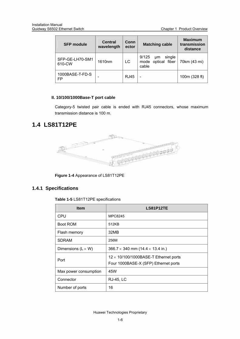
1.4 LS81T12PE
Figure 1-4 Appearance of LS81T12PE
1.4.1 Specifications
Table 1-5 LS81T12PE specifications
Item LS81P12TE
CPU MPC8245
Boot ROM 512KB
Flash memory 32MB
SDRAM 256M
Dimensions (L × W) 366.7 × 340 mm (14.4 × 13.4 in.)
Port 12 × 10/100/1000BASE-T Ethernet ports Four 1000BASE-X (SFP) Ethernet ports
Max power consumption 45W
Connector RJ-45, LC
Number of ports 16

Installation Manual Quidway S6502 Ethernet Switch Chapter 1 Product Overview
Huawei Technologies Proprietary
1-7
Item LS81P12TE
Port rate
1000 Mbps full duplex (optical port) 10 Mbps half/full duplex (electric port) 100 Mbps half/full duplex (electric port) 1000M full duplex (electric port)
SFP module Refer to Table 1-4
Port cable and max transmission distance 100 m (328 ft) over category-5 twisted pair cable
Supported standard
IEEE 802.3z IEEE 802.3ab IEEE 802.1p IEEE 802.1Q IEEE 802.1D IEEE802.1X IEEE802.1s IEEE802.1w IEEE 802.3x IEEE 802.3ad IEEE802.3
1.4.2 Panel and LEDs
LS81T12PE has 12 × 10/100/1000BASE-T ports and four 1000BASE-X (SFP) ports, each has a status LED with it. Figure 1-5 illustrates the front panel of an LS81T12PE.
Figure 1-5 LS81T12PE front panel
The status LEDs on an LS81T12PE are described in Table 1-6.
Table 1-6 Description of LEDs on the front panel of an LS81T12PE
LED Status
OFF The link is down or no link presented.
ON The link is active. LINK/ACT
Blinking Data is being transmitted or received through the port.
Installation Manual Quidway S6502 Ethernet Switch Chapter 1 Product Overview
Huawei Technologies Proprietary
1-8
1.4.3 Port Cable
Refer to 1.3.3 for information about the port cable required by an LS81T12PE.
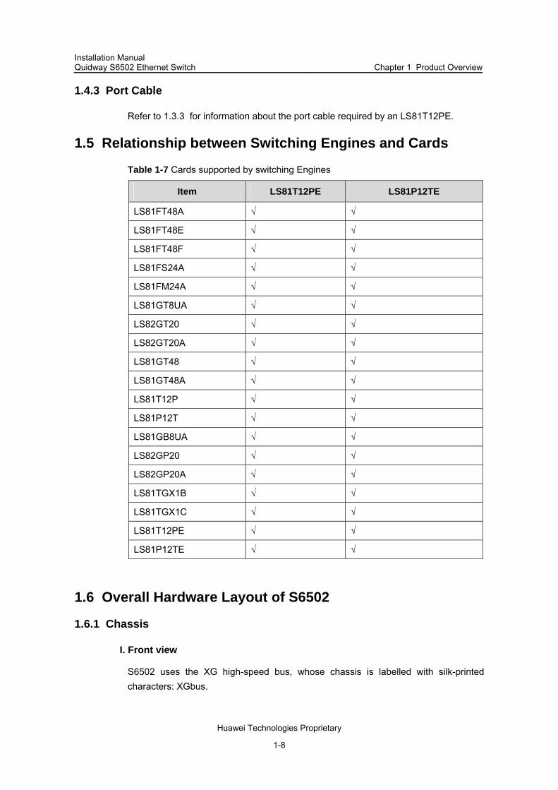
1.5 Relationship between Switching Engines and Cards
Table 1-7 Cards supported by switching Engines
Item LS81T12PE LS81P12TE
LS81FT48A √ √
LS81FT48E √ √
LS81FT48F √ √
LS81FS24A √ √
LS81FM24A √ √
LS81GT8UA √ √
LS82GT20 √ √
LS82GT20A √ √
LS81GT48 √ √
LS81GT48A √ √
LS81T12P √ √
LS81P12T √ √
LS81GB8UA √ √
LS82GP20 √ √
LS82GP20A √ √
LS81TGX1B √ √
LS81TGX1C √ √
LS81T12PE √ √
LS81P12TE √ √
1.6 Overall Hardware Layout of S6502
1.6.1 Chassis
I. Front view
S6502 uses the XG high-speed bus, whose chassis is labelled with silk-printed characters: XGbus.

Installation Manual Quidway S6502 Ethernet Switch Chapter 1 Product Overview
Huawei Technologies Proprietary
1-9
The front panel is occupied by the power supply modules, RESET button, COM port (for PoE management), console port, 10Base-T/100Base-TX management port and its status LED, fan LED, card status LED.
S6502 provides two horizontal slots, with the upper for SRPU and the lower for LPU. The SRPU is mandatory, and the lower slot can hold many types of LPU cards.
Figure 1-6 illustrates the front panel of an S6502 switch, where the LS81P12TE is inserted in slot 0 and LS81GT8UE in slot 1.
(11)
(10)
(1) (2) (5) (6)(4)(3) (7)
(8)
(9)
(1) (2)
(11)
(10)
(1) (2) (5) (6)(4)(3) (7)
(8)
(9)
(1) (2)
(1) Power switch (2) Power module handle (3) RESET button (4) COM port (5) Console port (6) Management prot (7) Fan LED (8) Card status LED (9) Fan tray (10) Slot 1 (11) Slot 0
Figure 1-6 The front panel of an S6502 switch
Power modules
The power modules, in 1+1 redundancy, are at the top left corner of the chassis. You can select to be AC or DC powered. There are LED, power switch and power input socket on a power supply module (refer to Section 4.5 for more information).
RESET button
You can reset the system with the RESET button.
COM port
Table 1-8 COM port attributes
Item Description
Connector RJ45
Number of connector 1
Supported standard Asynchronous EIA/TIA-232
Baudrate ≤ 115200 bps (defaults to 9600 bps)
Transmission distance ≤ 15m (49.2 ft)
Function For monitoring external PoE power supply when connected to it

Installation Manual Quidway S6502 Ethernet Switch Chapter 1 Product Overview
Huawei Technologies Proprietary
1-10
Note:
S6502 switch can provide power to the powered devices (PDs) connected, such as IP phone sets, WLAN access point (AP), through the external PoE power distribution unit and its card supporting PoE function.
Console port
The console port matches RJ45 connector and can be connected to a PC with an asynchronous serial port cable, for local system debugging, configuration, maintenance, management, system software loading and so on. It also can be used to connect to a Modem device for remote debugging, configuration, maintenance, management and other similar tasks.
Table 1-9 Console port attributes
Item Description
Connector RJ45
Number of connector 1
Electric standard Asynchronous EIA/TIA-232
Baudrate ≤ 115200 bps, defaults to 9600 bps
Transmission distance ≤ 15m (49.2 ft)
Function For connection with an ASCII terminal Being connected to the serial interface of a local PC or
a remote PC running terminal emulation software
Management port (10Base-T/100Base-TX)
The management port matches RJ45 connector and can be used to connect to a PC for local system debugging, system software loading and other similar tasks, or to a remote a network management station (NMS) for remote management.
Table 1-10 Management port attributes
Item Description
Connector RJ45
Number of connector 1
Port rate 10 Mbps, half/full duplex 100 Mbps, half/full duplex MDI-X
Port cable and max transmission distance 100 m (328 ft) over category-5 twisted pair cable
Installation Manual Quidway S6502 Ethernet Switch Chapter 1 Product Overview
Huawei Technologies Proprietary
1-11
Item Description
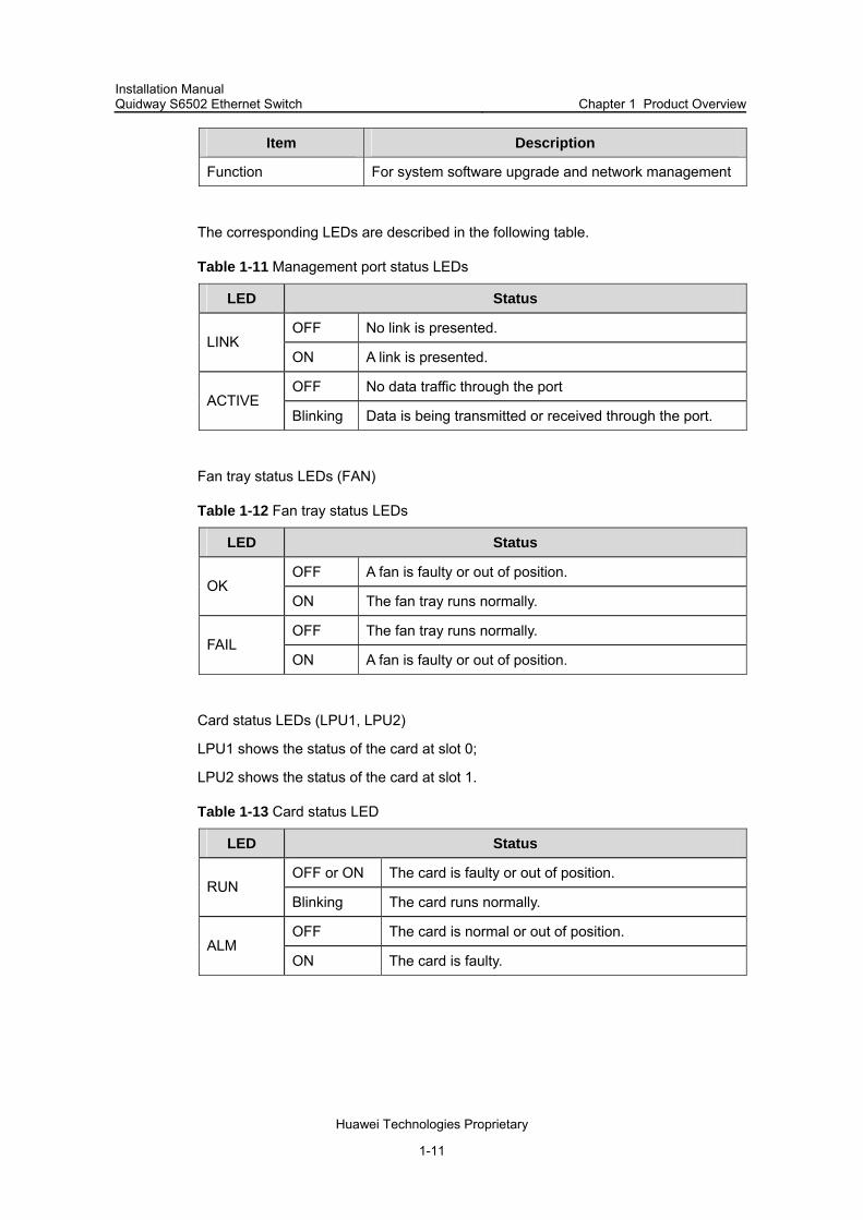
Function For system software upgrade and network management
The corresponding LEDs are described in the following table.
Table 1-11 Management port status LEDs
LED Status
OFF No link is presented. LINK
ON A link is presented.
OFF No data traffic through the port ACTIVE
Blinking Data is being transmitted or received through the port.
Fan tray status LEDs (FAN)
Table 1-12 Fan tray status LEDs
LED Status
OFF A fan is faulty or out of position. OK
ON The fan tray runs normally.
OFF The fan tray runs normally. FAIL
ON A fan is faulty or out of position.
Card status LEDs (LPU1, LPU2)
LPU1 shows the status of the card at slot 0;
LPU2 shows the status of the card at slot 1.
Table 1-13 Card status LED
LED Status
OFF or ON The card is faulty or out of position. RUN
Blinking The card runs normally.
OFF The card is normal or out of position. ALM
ON The card is faulty.

Installation Manual Quidway S6502 Ethernet Switch Chapter 1 Product Overview
Huawei Technologies Proprietary
1-12
II. Rear view
(1) (2)
(1) PoE power input (2) Grounding screw
Figure 1-7 Rear view of an S6502 chassis
An S6502 chassis provides -48V DC input for connection with external PoE power distribution unit.
Note:
The backplane, SRPU, power module and fan tray all are required components in S6502.
1.6.2 Backplane
The backplane mainly functions in:
Providing communication channels for signal exchange between cards. Providing support for card hot-swapping Auto-detecting the card type inserted at slots Leading in electric power for distributed supply to the system Leading in signal lines for monitoring the fan tray and power frame
1.6.3 Power Supplies

Installation Manual Quidway S6502 Ethernet Switch Chapter 1 Product Overview
Huawei Technologies Proprietary
1-13
Note:
The S6502 supports either AC or DC input, but they cannot run concurrently. You can choose the specific type as needed. Although the system can operate normally when one power module is working, the S6502 still provides two slots for power modules, in attempt to support 1+1 redundancy. The power module on the S6502 is hot-swappable.
The AC power supply module and DC power supply module of an S6502 Ethernet switch meet the following requirements:
AC power module and DC power module have exactly the same dimensions and installation ports;
AC power module and DC power module have exactly the same type of output plug-in units located at the same position;
AC power module and DC power module cannot be both inserted in one S6502.
I. AC power module
For AC power supply, you must use AC power module and AC power socket.
Table 1-14 AC power module specifications
Item AC power module
Rated voltage 100 VAC to 240 VAC.; 50 Hz or 60 Hz
Max voltage range 90 VAC to 264 VAC.; 50 Hz or 60 Hz
Max power output 300 W
II. DC power module
For DC power supply, you must use DC power module and DC power socket.
Table 1-15 DC Power supply specifications
Item DC power module
Rated voltage -48 VDC to -60 VDC
Max voltage range -36 VDC to -72 VDC
Max power output 300 W

Installation Manual Quidway S6502 Ethernet Switch Chapter 1 Product Overview
Huawei Technologies Proprietary
1-14
1.6.4 External PoE Power Supply
When connected to an external PoE power supply, the S6502 can supply power to remote PD devices, such as IP phone sets and WLAN access point hosts, through its card which support PoE function.
Figure 1-8 Appearance of an external PoE power supply
Note:
S6502 supports an external PoE power supply with up to 1500 W power output. A single PSE2500-A1 power supply module can provide output power of 1250 W with 100 VAC to 140 VAC input voltage, and two modules up to 2400 W output. Three power supply modules are required to provide output power of 2400 W if power supply redundancy is desired. When with 200 VAC to 240VAC input voltage, a single PSE2500-A1 power supply module can provide 2500 W output. Two power modules are required if power supply redundancy is desired.
1.6.5 Fan Tray
The fan tray is at the right side of an S6502 chassis, and directly connected to the backplane through a connector. The fan fault signals are summarized and transmitted from the backplane to the SRPU for further processing. The fan tray is hot-swappable.

Installation Manual Quidway S6502 Ethernet Switch Chapter 1 Product Overview
Huawei Technologies Proprietary
1-15
Figure 1-9 Fan tray on an S6502
1.7 Technical Specifications
Table 1-16 System specifications
Item S6502
Physical dimensions (H × W × D) 130.5 x 436 x 400 mm (5.12 x 17.2 x 15.8 in.)
Weight (fully configured) ≤44 lb (20 kg )
Number of SRPU slot 1
Number of LPU slot 1
Max GE ports 64
Max FE ports 48
MTBF (mean time between failures) 218,000 h
MTTR (mean time to repair) 1 h
AC
Rated voltage: 100 VAC to 240 VAC, 50 Hz or 60 Hz Max voltage range: 90 VAC to 264 VAC, 50 Hz or 60 Hz
Rated voltage: -48 VDC to -60 VDC Max voltage range: -36 VDC to -72 VDC
Input voltage
DC
PoE input voltage: --55 V to -46 V, 55.0 A
Operating temperature 0ºC to 45ºC (32ºF to 113ºF)
Operating humidity (non-condensing) 10% to 90%

Installation Manual Quidway S6502 Ethernet Switch Chapter 2 Line Processing Unit
Huawei Technologies Proprietary
2-1
Chapter 2 Line Processing Unit
2.1 Brief Introduction to LPU
Based on industry standard and complying with modular designing idea, S6502 combines advantages of the mainstream products in the field. The reasonable division of the system module ports makes it has a sound system structure and standardized and independent functional modules. By far, the S6502 provides 10/100/1000 Mbps autosensing Ethernet electrical ports, 100 Mbps Ethernet (single mode/multimode) optical ports, GE (single mode/multimode) GBIC optical ports, SFP optical ports and 10G optical ports.
The following sections describe the LPU specifications and performances in detail.
2.2 LS81FT48A-48-port 10Base-T/100Base-TX Fast Ethernet Card
Figure 2-1 LS81FT48A appearance
2.2.1 Introduction to Card
This LPU provides 48 10/100 Mbps auto-sensing Ethernet electrical interfaces.
Table 2-1 LS81FT48A attribute
Attribute LS81FT48A
CPU MPC850
BootROM 512 KB
SDRAM 64M
Dimensions (L × W) 366.7 × 340 mm (14.4 × 13.4 in.)
Maximum power consumption 75 W
Connector RJ-45
Number of interfaces 48

Installation Manual Quidway S6502 Ethernet Switch Chapter 2 Line Processing Unit
Huawei Technologies Proprietary
2-2
Attribute LS81FT48A
Interface transmission speed10/100 Mbps half-/full-duplex MDI/MDI-X auto-sensing
Matching cable and maximum transmission distance
Category-5 twisted pair with maximum transmission distance of 100 m (328 ft)
Conformed standard
IEEE802.3 IEEE802.3x IEEE802.3ad IEEE802.1p IEEE802.1D IEEE802.1Q IEEE802.1X IEEE802.1s IEEE802.1w
2.2.2 Panel and LEDs
Figure 2-2 LS81FT48A panel
Every 100 Mbps Ethernet port has a green LED. The following table describes the LED state.
Table 2-2 LED state description of LS81FT48A
LED State Description
OFF No link is present.
ON A link is present LINK/ACT
Blinking Packets are being transmitted/received on the port.
2.2.3 Matching Cable
The matching cable to the interface is category-5 twisted pair with a maximum transmission distance of 100 m (328 ft).

Installation Manual Quidway S6502 Ethernet Switch Chapter 2 Line Processing Unit
Huawei Technologies Proprietary
2-3
2.3 LS81FT48E-48-port 10/100Base-T Fast Ethernet Card
Figure 2-3 LS81FT48E appearance
2.3.1 Introduction to Card
This LPU provides 48 × 10/100 Mbps auto-sensing Ethernet electrical interfaces.
Table 2-3 LS81FT48E attribute
Attribute LS81FT48E
CPU MPC8241
BootROM 512 KB
SDRAM 128M
Dimensions (L × W) 366.7 × 340 mm (14.4 × 13.4 in.)
Maximum power consumption 35 W
Connector RJ-45
Number of interfaces 48
Interface transmission speed
10/100 Mbps half-/full-duplex MDI/MDI-X auto-sensing
Matching cable and maximum transmission distance
Category-5 twisted pair with maximum transmission distance of 100 m (328 ft)

Installation Manual Quidway S6502 Ethernet Switch Chapter 2 Line Processing Unit
Huawei Technologies Proprietary
2-4
Attribute LS81FT48E
Conformed standard
IEEE802.3 IEEE 802.3ad IEEE802.3x IEEE802.1p IEEE802.1D IEEE802.1Q IEEE802.1X IEEE802.1s IEEE802.1w
2.3.2 Panel and LEDs
Figure 2-4 LS81FT48E panel
Every port has a green LED. The following table describes the LED state.
Table 2-4 LED state description of LS81FT48E
LED State Description
OFF No link is present.
ON A link is present LINK/ACT
Blinking Packets are being transmitted/received on the port.
2.3.3 Matching Cable
The matching cable to the interface is category-5 twisted pair with a maximum transmission distance of 100 m (328 ft).

Installation Manual Quidway S6502 Ethernet Switch Chapter 2 Line Processing Unit
Huawei Technologies Proprietary
2-5
2.4 LS81FT48F-PoE-Supported 48-port 10/100Base-T Fast Ethernet Card
Figure 2-5 LS81FT48F appearance
2.4.1 Introduction to Card
This LPU provides 48 × 10/100 Mbps auto-sensing Ethernet electrical interface service channels. And all the interfaces support PoE, that is, to implement remote power supply to PDs through Ethernet twisted pair cables.
Table 2-5 LS81FT48F attribute
Attribute LS81FT48F
CPU MPC8241
BootROM 512 KB
SDRAM 128M
Dimensions (L × W) 366.7 × 340 mm (14.4 × 13.4 in.)
Maximum power consumption 35 W
Connector RJ-45
Number of i8nterfaces 48
Interface transmission speed
10/100 Mbps half-/full-duplex MDI/MDI-X auto-sensing
Matching cable and maximum transmission distance
Category-5 twisted pair with maximum transmission distance of 100 m (328 ft)
Maximum PoE distance 100m (328 ft)

Installation Manual Quidway S6502 Ethernet Switch Chapter 2 Line Processing Unit
Huawei Technologies Proprietary
2-6
Attribute LS81FT48F
Maximum power each port can provide
Each port provides a maximum power of 15.4 W for the connected device.
Conformed standard
IEEE802.3 IEEE802.3x IEEE 802.3ad IEEE802.1p IEEE802.1D IEEE802.1Q IEEE802.1X IEEE802.1s IEEE802.1w IEEE802.3af
2.4.2 Panel and LEDs
Figure 2-6 LS81FT48F panel
Every port has a green LED. The following table describes the LED state.
Table 2-6 LED state description of LS81FT48F
LED State Description
Off No link is present.
On A link is present LINK/ACT
Blinking Packets are being transmitted/received on the port.
2.4.3 Matching Cable
The matching cable to the interface is category-5 twisted pair with a maximum transmission distance of 100 m (328 ft).

Installation Manual Quidway S6502 Ethernet Switch Chapter 2 Line Processing Unit
Huawei Technologies Proprietary
2-7
2.5 LS81FM24A/LS81FS24A-24-port 100Base-FX MMF/SMF Fast Ethernet Card
Figure 2-7 LS81FM24A/LS81FS24A appearance
2.5.1 Introduction to Card
This LPU provides 24 100 Mbps auto-sensing Ethernet optical interfaces.
Table 2-7 LS81FM24A/LS81FS24A attribute
Description Attribute
LS81FM24A LS81FS24A
CPU MPC850
BootROM 512 KB
SDRAM 64M
Dimensions (L × W) 366.7 × 340 mm (14.4 × 13.4 in.)
Maximum power consumption
70 W
Connector MT-RJ
Number of interfaces 24
Interface transmission speed
100 Mbps full-duplex
Conformed standard
IEEE802.3 IEEE802.3x IEEE802.3ad IEEE802.1p IEEE802.1D IEEE802.1Q IEEE802. 1X IEEE802.1s IEEE802.1w

Installation Manual Quidway S6502 Ethernet Switch Chapter 2 Line Processing Unit
Huawei Technologies Proprietary
2-8
Description Attribute
LS81FM24A LS81FS24A
Optical fiber and maximum transmission distance
62.5/125 µm multimode optical fiber cable with the maximum transmission distance of 2 km (1.2 mi)
9/125 µm single mode optical fiber cable with the maximum transmission distance of 15 km (9.3)
2.5.2 Panel and LEDs
Figure 2-8 LS81FM24A panel
Every 100 Mbps electrical port has a green LED. The following table describes the LED state.
Table 2-8 LED state description of LS81FM24A
LED State Description
ON (LINK) The interface is properly connected to another interface.
OFF (LINK) The interface is not connected to any other interface. LINK/ACT
Blinking (ACT) Packets are being transmitted/received on the port.
2.5.3 Matching Cable
Table 2-9 Matching cable available for LS81FM24A/LS81FS24A
Cards Central
wavelength
Connector Matching cable
Maximum transmission
distance
LS81FM24A 850 nm
62.5/125 µm multimode optical fiber cable
2 km (1.2 mi)
LS81FS24A 1310 nm
MT-RJ 9/125 µm single mode optical fiber cable
15 km (about 9 mi)

Installation Manual Quidway S6502 Ethernet Switch Chapter 2 Line Processing Unit
Huawei Technologies Proprietary
2-9
2.6 LS81FP48-48-port 100Base-FX(SFP) Ethernet Card
Figure 2-9 LS81FP48
2.6.1 Introduction
This LPU provides 48 × 100 Mbps full duplex SFP Ethernet optical ports.
Table 2-10 LS81FM24A/LS81FS24A technical specifications
Attribute LS81FP48
CPU MPC8241
Boot ROM 512 KB
SDRAM 128M
Dimensions (L × W) 366.7 × 340 mm (14.4 × 13.4 in.)
Max power consumption 36.5 W
Connector LC
Number of ports 48
Port transmission speed 100 Mbps full duplex
SFP module
100BASE-FX-MM-SFP 100BASE-FX-SM-SFP 100BASE-FX-SM-LR-SFP 100BASE-FX-SM-VR-SFP
Installation Manual Quidway S6502 Ethernet Switch Chapter 2 Line Processing Unit
Huawei Technologies Proprietary
2-10
Attribute LS81FP48
Conformed standard
IEEE802.3 IEEE802.3u IEEE802.3x IEEE802.3ad IEEE802.1p IEEE802.1D IEEE802.1Q IEEE802. 1X IEEE802.1s IEEE802.1w
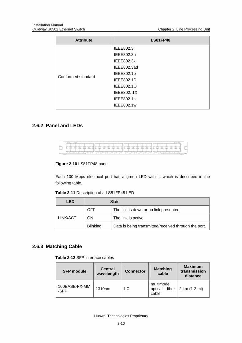
2.6.2 Panel and LEDs
Figure 2-10 LS81FP48 panel
Each 100 Mbps electrical port has a green LED with it, which is described in the following table.
Table 2-11 Description of a LS81FP48 LED
LED State
OFF The link is down or no link presented.
ON The link is active. LINK/ACT
Blinking Data is being transmitted/received through the port.
2.6.3 Matching Cable
Table 2-12 SFP interface cables
SFP module Central wavelength Connector Matching
cable Maximum
transmission distance
100BASE-FX-MM-SFP 1310nm LC
multimode optical fiber cable
2 km (1.2 mi)

Installation Manual Quidway S6502 Ethernet Switch Chapter 2 Line Processing Unit
Huawei Technologies Proprietary
2-11
SFP module Central wavelength Connector Matching
cable Maximum
transmission distance
100BASE-FX-SM-SFP 1310nm 15 km (9.3 mi)
100BASE-FX-SM-LR-SFP 1310nm 40 km (24.9 mi)
100BASE-FX-SM-VR-SFP 1550nm
9/125 µm single mode optical fiber cable
70km (43 mi)
2.7 LS81GT8UA-8-port 10/100/1000Base-T Ethernet Card
Figure 2-11 LS81GT8UA appearance
2.7.1 Introduction to Card
This LPU provides eight 10/100/1000 Mbps auto-sensing Ethernet electrical interfaces.
Table 2-13 LS81GT8UA attribute
Attribute LS81GT8UA
CPU MPC850
BootROM 512KB
SDRAM 64M
Dimensions (L × W) 366.7 × 340 mm (14.4 × 13.4 in.)
Maximum power consumption 55 W
Connector RJ-45
Number of interfaces 8
Interface transmission speed
10/100/1000 Mbps half-/full-duplex MDI/MDI-X auto-sensing
Matching cable and maximum transmission distance
Category-5 twisted pair with maximum transmission distance of 100 m (328 ft)

Installation Manual Quidway S6502 Ethernet Switch Chapter 2 Line Processing Unit
Huawei Technologies Proprietary
2-12
Attribute LS81GT8UA
Conformed standard
IEEE 802.3ab IEEE802.3 IEEE802.3x IEEE802.3ad IEEE802.1p IEEE802.1D IEEE802.1Q IEEE802.1X IEEE802.1s IEEE802.1w
2.7.2 Panel and LEDs
Figure 2-12 LS81GT8UA panel
Every port has two LEDs. The following table describes the LED state.
Table 2-14 LED state description of LS81GT8UA
LED State
Off No link is present. LINK
On A link is present.
Off No packets are transmitted/received on the port.ACT
Blinking Packets are being transmitted/received on the port.
2.7.3 Matching Cable
The matching cable to the interface is category-5 twisted pair with a maximum transmission distance of 100 m (328 ft).

Installation Manual Quidway S6502 Ethernet Switch Chapter 2 Line Processing Unit
Huawei Technologies Proprietary
2-13
2.8 LS81GT8UE-8-port 10/100/1000Base-T Ethernet Card
Figure 2-13 LS81GT8UE appearance
2.8.1 Introduction to Card
This LPU provides eight 10/100/1000 Mbps auto-sensing Ethernet electrical interfaces.
Table 2-15 LS81GT8UE attribute
Attribute LS81GT8UE
CPU MPC850
BootROM 512 KB
SDRAM 64M
Dimensions (L × W) 366.7 × 340 mm (14.4 × 13.4 in.)
Maximum power consumption 12 W
Connector RJ-45
Number of interfaces 8
Interface transmission speed
10/100/1000 Mbps half-/full-duplex MDI/MDI-X auto-sensing
Matching cable and maximum transmission distance
Category-5 twisted pair with maximum transmission distance of 100 m (328 ft)

Installation Manual Quidway S6502 Ethernet Switch Chapter 2 Line Processing Unit
Huawei Technologies Proprietary
2-14
Attribute LS81GT8UE
Conformed standard
IEEE 802.3ab IEEE802.3 IEEE802.3x IEEE802.1D IEEE802.1Q IEEE802.1X IEEE802.1s IEEE802.1w
2.8.2 Panel and LEDs
Figure 2-14 LS81GT8UE panel
Every port has two LEDs. The following table describes the LED state.
Table 2-16 LED state description of LS81GT8UE
LED State
OFF No link is present. LINK
ON A link is present.
OFF No packets are transmitted/received on the port. ACT
Blinking Packets are being transmitted/received on the port.
2.8.3 Matching Cable
The matching cable to the interface is category-5 twisted pair with a maximum transmission distance of 100 m (328 ft).

Installation Manual Quidway S6502 Ethernet Switch Chapter 2 Line Processing Unit
Huawei Technologies Proprietary
2-15
2.9 LS82GT20-20-port 10/100/1000Base-T Ethernet Card
Figure 2-15 LS82GT20 appearance
2.9.1 Introduction to Card
This LPU provides 20 x 10/100/1000 Mbps auto-sensing Ethernet electrical interfaces.
Table 2-17 LS82GT20 attribute
Attribute LS82GT20
CPU MPC8241
BootROM 512 KB
SDRAM 64M
Dimensions (L × W) 366.7 × 340 mm (14.4 × 13.4 in.)
Maximum power consumption 45 W
Connector RJ-45
Number of interfaces 20
Interface transmission speed
10/100 Mbps half-/full-duplex 1000 Mbps full-duplex MDI/MDI-X auto-sensing
Matching cable and maximum transmission distance
Category-5 twisted pair with maximum transmission distance of 100 m (328 ft)
Conformed standard
IEEE 802.3ab IEEE802.3 IEEE802.3x IEEE802.1p IEEE802.1D IEEE802.1Q IEEE802.1X IEEE802.1w IEEE802.1ad IEEE802.1s

Installation Manual Quidway S6502 Ethernet Switch Chapter 2 Line Processing Unit
Huawei Technologies Proprietary
2-16
2.9.2 Panel and LEDs
Figure 2-16 LS82GT20 panel
Every port has one LED. The following table describes the LED state.
Table 2-18 LED state description of LS82GT20
LED State Description
OFF No link is present.
ON A link is present LINK/ACT
Blinking Packets are being transmitted/received on the port.
2.9.3 Matching Cable
The matching cable to the interface is category-5 twisted pair with a maximum transmission distance of 100 m (328 ft).
2.10 LS82GT20A-20-port 10/100/1000Base-T Ethernet Card
Figure 2-17 LS82GT20A appearance
2.10.1 Introduction to Card
This LPU provides 20 x 10/100/1000 Mbps auto-sensing Ethernet electrical interfaces.

Installation Manual Quidway S6502 Ethernet Switch Chapter 2 Line Processing Unit
Huawei Technologies Proprietary
2-17
Table 2-19 LS82GT20A attribute
Attribute LS82GT20A
CPU MPC8241
BootROM 512 KB
SDRAM 128M
Dimensions (L × W) 366.7 × 340 mm (14.4 × 13.4 in.)
Maximum power consumption 45 W
Connector RJ-45
Number of interfaces 20
Interface transmission speed
10/100 Mbps half-/full-duplex 1000 Mbps full-duplex MDI/MDI-X auto-sensing
Matching cable and maximum transmission distance
Category-5 twisted pair with maximum transmission distance of 100 m (328 ft)
Conformed standard
IEEE 802.3ab IEEE802.3 IEEE802.3x IEEE802.1p IEEE802.1D IEEE802.1Q IEEE802.1X IEEE802.1w IEEE802.1ad IEEE802.1s
2.10.2 Panel and LEDs
Figure 2-18 LS82GT20A panel
Every port has one LED. The following table describes the LED state.
Installation Manual Quidway S6502 Ethernet Switch Chapter 2 Line Processing Unit
Huawei Technologies Proprietary
2-18
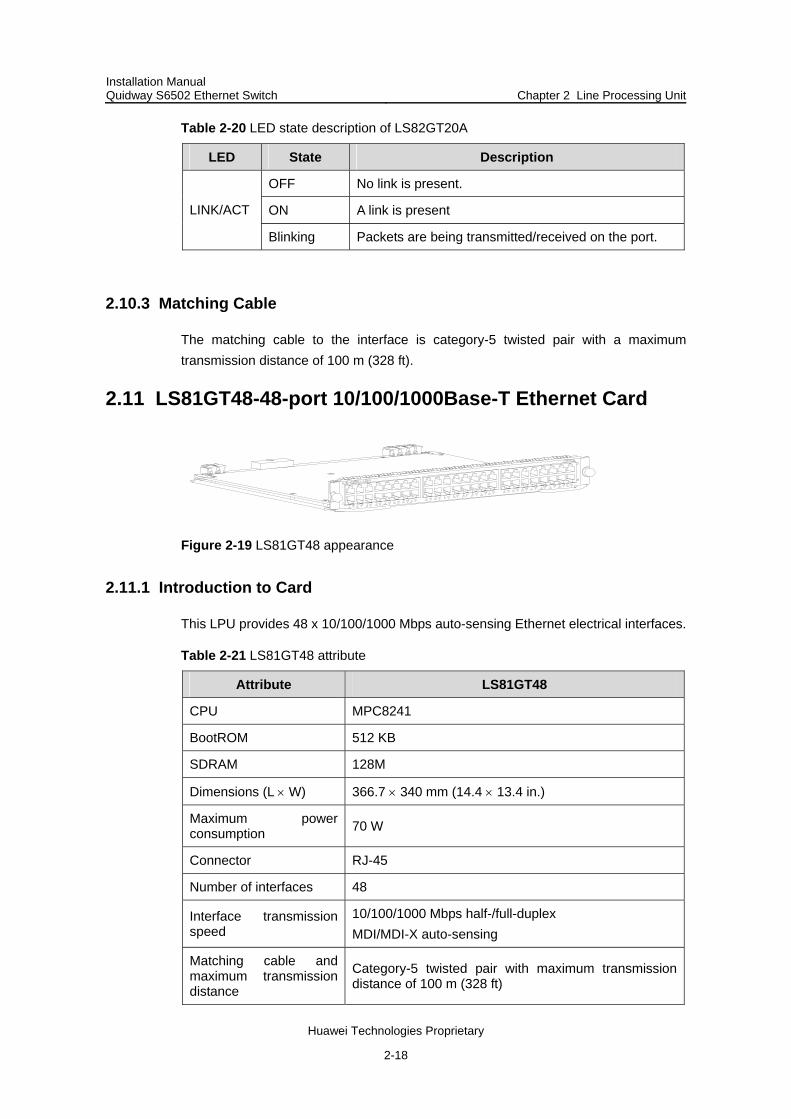
Table 2-20 LED state description of LS82GT20A
LED State Description
OFF No link is present.
ON A link is present LINK/ACT
Blinking Packets are being transmitted/received on the port.
2.10.3 Matching Cable
The matching cable to the interface is category-5 twisted pair with a maximum transmission distance of 100 m (328 ft).
2.11 LS81GT48-48-port 10/100/1000Base-T Ethernet Card
Figure 2-19 LS81GT48 appearance
2.11.1 Introduction to Card
This LPU provides 48 x 10/100/1000 Mbps auto-sensing Ethernet electrical interfaces.
Table 2-21 LS81GT48 attribute
Attribute LS81GT48
CPU MPC8241
BootROM 512 KB
SDRAM 128M
Dimensions (L × W) 366.7 × 340 mm (14.4 × 13.4 in.)
Maximum power consumption 70 W
Connector RJ-45
Number of interfaces 48
Interface transmission speed
10/100/1000 Mbps half-/full-duplex MDI/MDI-X auto-sensing
Matching cable and maximum transmission distance
Category-5 twisted pair with maximum transmission distance of 100 m (328 ft)

Installation Manual Quidway S6502 Ethernet Switch Chapter 2 Line Processing Unit
Huawei Technologies Proprietary
2-19
Attribute LS81GT48
Conformed standard
IEEE 802.3ab IEEE802.3 IEEE802.3x IEEE802.1p IEEE802.1D IEEE802.1Q IEEE802.1X IEEE802.1s IEEE802.1w
2.11.2 Panel and LEDs
Figure 2-20 LS81GT48 panel
Every port has a LED. The following table describes the LED state.
Table 2-22 LED state description of LS81GT48
LED State Description
Off No link is present.
On A link is present LINK/ACT
Blinking Packets are being transmitted/received on the port.
2.11.3 Matching Cable
The matching cable to the interface is category-5 twisted pair with a maximum transmission distance of 100 m (328 ft).

Installation Manual Quidway S6502 Ethernet Switch Chapter 2 Line Processing Unit
Huawei Technologies Proprietary
2-20
2.12 LS81GT48A-PoE-Supported 48-port 10/100/1000Base-T Ethernet Card
Figure 2-21 LS81GT48A appearance
2.12.1 Introduction to Card
This LPU provides 48 x 10/100/1000 Mbps auto-sensing Ethernet electrical interface service channels. And all the interfaces support PoE, that is, to implement remote power supply to PDs through Ethernet twisted pair cables.
Table 2-23 LS81GT48A attribute
Attribute LS81GT48A
CPU MPC8241
BootROM 512 KB
SDRAM 128M
Dimensions (L × W) 366.7 × 340 mm (14.4 × 13.4 in.)
Maximum power consumption 70 W
Connector RJ-45
Number of interfaces 48
Interface transmission speed
10/100/1000 Mbps half-/full-duplex MDI/MDI-X auto-sensing
Matching cable and maximum transmission distance
Category-5 twisted pair with maximum transmission distance of 100 m (328 ft)
Maximum PoE distance 100m (328 ft)
Maximum power each port can provide
Each port provides a maximum power of 15.4 W for the connected device.

Installation Manual Quidway S6502 Ethernet Switch Chapter 2 Line Processing Unit
Huawei Technologies Proprietary
2-21
Attribute LS81GT48A
Conformed standard
IEEE 802.3ab IEEE802.3 IEEE802.3x IEEE802.1p IEEE802.1D IEEE802.1Q IEEE802.1X IEEE802.1s IEEE802.1w IEEE802.3af
2.12.2 Panel and LEDs
Figure 2-22 LS81GT48A panel
Every port has a LED. The following table describes the LED state.
Table 2-24 LED state description of LS81GT48A
LED State Description
Off No link is present.
On A link is present LINK/ACT
Blinking Packets are being transmitted/received on the port.
2.12.3 Matching Cable
The matching cable to the interface is category-5 twisted pair with a maximum transmission distance of 100 m (328 ft).

Installation Manual Quidway S6502 Ethernet Switch Chapter 2 Line Processing Unit
Huawei Technologies Proprietary
2-22
2.13 LS81T12P-12-port 10/100/1000Base-T + 4-port 1000Base-X (SFP) Ethernet Card
Figure 2-23 LS81T12P appearance
2.13.1 Introduction to Card
This LPU provides 12 x 10/100/1000 Mbps auto-sensing Ethernet electrical interfaces and four 1000 Mbps full-duplex SFP interfaces.
Table 2-25 LS81T12P attribute
Attribute LS81T12P
CPU MPC8241
BootROM 512 KB
SDRAM 128M
Dimensions (L × W) 366.7 × 340 mm (14.4 × 13.4 in.)
Maximum power consumption 40 W
Connector RJ-45, LC
Number of interfaces 16
Interface transmission speed
1000 Mbps full-duplex (optical/electrical) 10/100 Mbps half-/full-duplex (electrical)
SFP modules Refer to Table 2-27
Matching cable and maximum transmission distance
Category-5 twisted pair with maximum transmission distance of 100 m (328 ft)

Installation Manual Quidway S6502 Ethernet Switch Chapter 2 Line Processing Unit
Huawei Technologies Proprietary
2-23
Attribute LS81T12P
Conformed standard
IEEE 802.3z IEEE 802.3ab IEEE 802.1p IEEE 802.1Q IEEE 802.1D IEEE802.1X IEEE802.1s IEEE802.1w IEEE 802.3x IEEE 802.3ad IEEE802.3
2.13.2 Panel and LEDs
Figure 2-24 LS81T12P panel
The following table describes the LED state.
Table 2-26 LED state description of LS81T12P
LED State Description
OFF No link is present.
ON A link is present LINK/ACT
Blinking Packets are being transmitted/received on the port.

Installation Manual Quidway S6502 Ethernet Switch Chapter 2 Line Processing Unit
Huawei Technologies Proprietary
2-24
2.13.3 Matching Cable
I. Matching cable for 4-port 1000Base-X (SFP) optical interface
Table 2-27 Description of 1000BASE-X (SFP) cable
SFP module Central wavelength
Connector Matching cable
Maximum transmission
distance
50/125 µm multimode optical fiber cable
550 m (1804 ft)
1000BASE-SX-SFP 850nm LC 62.5/125 µm multimode optical fiber cable
275 m (902 ft)
1000BASE-LX-SFP 10 km (6 mi)
1000BASE-LH-SFP 1310nm LC
9/125 µm single mode optical fiber cable
30 km (about 19 mi)
1000BASE-ZX-LR-SFP
40 km (about 25 mi)
1000BASE-ZX-VR-SFP 70 km (43 mi)
1000BASE-ZX-UR-SFP
1550nm LC 9/125 µm single mode optical fiber cable
100km (62 mi)
SFP-GE-LH70-SM1470-CW 1470nm LC
9/125 µm single mode optical fiber cable
70km (43 mi)
SFP-GE-LH70-SM1490-CW 1490nm LC
9/125 µm single mode optical fiber cable
70km (43 mi)
SFP-GE-LH70-SM1510-CW 1510nm LC
9/125 µm single mode optical fiber cable
70km (43 mi)
SFP-GE-LH70-SM1530-CW 1530nm LC
9/125 µm single mode optical fiber cable
70km (43 mi)
SFP-GE-LH70-SM1550-CW 1550nm LC
9/125 µm single mode optical fiber cable
70km (43 mi)
SFP-GE-LH70-SM1570-CW 1570nm LC
9/125 µm single mode optical fiber cable
70km (43 mi)
SFP-GE-LH70-SM1590-CW 1590nm LC
9/125 µm single mode optical fiber cable
70km (43 mi)

Installation Manual Quidway S6502 Ethernet Switch Chapter 2 Line Processing Unit
Huawei Technologies Proprietary
2-25
SFP module Central wavelength
Connector Matching cable
Maximum transmission
distance
SFP-GE-LH70-SM1610-CW 1610nm LC
9/125 µm single mode optical fiber cable
70km (43 mi)
1000BASE-T-FD-SFP - RJ45 - 100m (328 ft)
II. 12-port 10/100/1000Base-T Ethernet interface
The matching cable to Ethernet interface is category-5 twisted pair with a maximum transmission distance of 100 m (328 ft).
2.14 LS81P12T-12-port 1000Base-X (SFP) + 4-port 10/100/1000Base-T Ethernet Card
Figure 2-25 LS81P12T appearance
2.14.1 Introduction to Card
This LPU provides 12 x 1000 Mbps full-duplex SFP interfaces and four 10/100/1000 Base-T auto-sensing Ethernet interfaces.
Table 2-28 LS81P12T attribute
Attribute LS81P12T
CPU MPC8241
BootROM 512 KB
SDRAM 128M

Installation Manual Quidway S6502 Ethernet Switch Chapter 2 Line Processing Unit
Huawei Technologies Proprietary
2-26
Attribute LS81P12T
Dimensions (L × W) 366.7 × 340 mm (14.4 × 13.4 in.)
Maximum power consumption 35 W
Connector RJ-45, LC
Number of interfaces 16
Interface transmission speed 1000 Mbps full-duplex (optical/electrical) 10/100 Mbps half-/full-duplex (electrical)
SFP modules Refer to Table 2-27
Matching cable and maximum transmission distance
Category-5 twisted pair with maximum transmission distance of 100 m (328 ft)
Conformed standard
IEEE 802.3z IEEE 802.3ab IEEE 802.1p IEEE 802.1Q IEEE 802.1D IEEE802.1X IEEE802.1s IEEE802.1w IEEE 802.3x IEEE 802.3ad IEEE802.3 IEEE802.3u
2.14.2 Panel and LEDs
Figure 2-26 LS81P12T panel
The following table describes the LED state.
Table 2-29 LED state description of LS81P12T
LED State Description
OFF No link is present.
ON A link is present LINK/ACT
Blinking Packets are being transmitted/received on the port.

Installation Manual Quidway S6502 Ethernet Switch Chapter 2 Line Processing Unit
Huawei Technologies Proprietary
2-27
2.14.3 Matching Cable
Refer to 2.13.3 .
2.15 LS81GB8UA-8-port 1000Base-X (GBIC) Ethernet Card
Figure 2-27 LS81GB8UA appearance
2.15.1 Introduction to Card
This LPU provides 8 1000 Mbps full-duplex Ethernet GBIC interfaces.
Table 2-30 LS81GB8UA attribute
Attribute LS81GB8UA
CPU MPC850
BootROM 512 KB
SDRAM 64M
Dimensions (L × W) 366.7 × 340 mm (14.4 × 13.4 in.)
Maximum power consumption 60 W
Connector SC, RJ-45
Number of interfaces 8
Interface transmission speed 1000 Mbps / Full-duplex
GBIC modules
1000BASE-SX-GBIC 1000BASE-LX-GBIC 1000BASE-LH-GBIC 1000BASE-ZX-LR-GBIC 1000BASE-ZX-VR-GBIC 1000BASE-ZX-UR-GBIC 1000BASE-T-FD-GBIC

Installation Manual Quidway S6502 Ethernet Switch Chapter 2 Line Processing Unit
Huawei Technologies Proprietary
2-28
Attribute LS81GB8UA
Conformed standard
IEEE 802.3 IEEE 802.3z IEEE 802.3x IEEE 802.3ad IEEE 802.3z IEEE 802.1p IEEE 802.1Q IEEE 802.1D IEEE 802.1X IEEE 802.1s IEEE 802.1w
Note:
GBIC module is a hot-swappable connector which can connect with optical fiber. A GBIC module provides one data receive/transmit channel.
2.15.2 Panel and LEDs
Figure 2-28 LS81GB8UA panel
Every 1000M GBIC port has a green LED. The following table describes the LED state.
Table 2-31 LED state description of LS81GB8UA
LED State Description
ON (LINK) The interface is properly connected to another interface.
OFF (LINK) The interface is not connected to any other interface.LINK/ACT
Blinking (ACT) Packets are being transmitted/received on the port.

Installation Manual Quidway S6502 Ethernet Switch Chapter 2 Line Processing Unit
Huawei Technologies Proprietary
2-29
2.15.3 Matching Cable
Table 2-32 Matching cable available for LS81GB8UA
GBIC module Central wavelength Connector Matching
cable Maximum
transmission distance
50/125 µm multimode optical fiber cable
500 m (1640 ft)
1000BASE-SX-GBIC 850 nm
62.5/125 µm multimode optical fiber cable
220 m (722 ft)
1000BASE-LX-GBIC 10 km (6 mi)
1000BASE-LH-GBIC
1310 nm 30 km (about 19 mi)
1000BASE-ZX- LR-GBIC
40 km (about 25 mi)
1000BASE-LX-VR-GBIC 70 km (43 mi)
1000BASE-ZX-UR-GBIC
1550 nm
SC
9/125 µm single mode optical fiber cable
100km (62 mi)
1000BASE-T-FD-GBIC - RJ-45 - 100 m (328 ft)
2.16 LS81GP8UB-8-port 1000Base-X (SFP) Ethernet Card
Figure 2-29 LS81GP8UB appearance
2.16.1 Introduction to Card
This LPU provides 8 1000 Mbps full-duplex SFP interfaces.

Installation Manual Quidway S6502 Ethernet Switch Chapter 2 Line Processing Unit
Huawei Technologies Proprietary
2-30
Table 2-33 LS81GP8UB attribute
Attribute LS81GP8UB
CPU MPC850
BootROM 512 KB
SDRAM 64M
Dimensions (L × W) 366.7 × 340 mm (14.4 × 13.4 in.)
Maximum power consumption 15 W
Connector LC, RJ-45
Number of interfaces 8
Interface transmission speed 1000 Mbps / Full-duplex
SFP modules Refer to Table 2-27
Conformed standard
IEEE 802.3 IEEE 802.3z IEEE 802.1p IEEE 802.1Q IEEE 802.1D IEEE 802.3x IEEE 802.3ad IEEE802.1X IEEE802.1s IEEE802.1w
2.16.2 Panel and LEDs
Figure 2-30 LS81GP8UB panel
The following table describes the LED state.

Installation Manual Quidway S6502 Ethernet Switch Chapter 2 Line Processing Unit
Huawei Technologies Proprietary
2-31
Table 2-34 LED state description of LS81GP8UB
LED State Description
OFF No link is present.
ON A link is present LINK/ACT
Blinking Packets are being transmitted/received on the port.
2.16.3 Matching Cable
Refer to Table 2-27.
2.17 LS82GP20-20-port 1000Base-X (SFP) Ethernet Card
Figure 2-31 LS82GP20 appearance
2.17.1 Introduction to Card
This LPU provides 20 1000 Mbps full-duplex SFP interfaces.
Table 2-35 LS82GP20 attribute
Attribute LS82GP20
CPU MPC8241
BootROM 512 KB
SDRAM 64M
Dimensions (L × W) 366.7 × 340 mm (14.4 × 13.4 in.)
Maximum power consumption 35 W
Connector LC, RJ-45
Number of interfaces 20
Interface transmission speed
1000 Mbps Full-duplex
Installation Manual Quidway S6502 Ethernet Switch Chapter 2 Line Processing Unit
Huawei Technologies Proprietary
2-32
Attribute LS82GP20
SFP modules Refer to Table 2-27
Conformed standard
IEEE802.3 IEEE802.3z IEEE802.1p IEEE802.1Q IEEE802.1D IEEE802.3x IEEE802.1X IEEE802.1w IEEE802.3ad IEEE802.1s
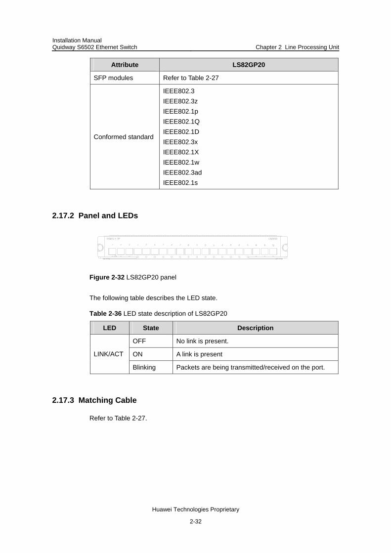
2.17.2 Panel and LEDs
Figure 2-32 LS82GP20 panel
The following table describes the LED state.
Table 2-36 LED state description of LS82GP20
LED State Description
OFF No link is present.
ON A link is present LINK/ACT
Blinking Packets are being transmitted/received on the port.
2.17.3 Matching Cable
Refer to Table 2-27.

Installation Manual Quidway S6502 Ethernet Switch Chapter 2 Line Processing Unit
Huawei Technologies Proprietary
2-33
2.18 LS82GP20A-20-port 1000Base-X (SFP) Ethernet Card
Figure 2-33 LS82GP20A appearance
2.18.1 Introduction to Card
This LPU provides 20 1000 Mbps full-duplex SFP interfaces.
Table 2-37 LS82GP20A attribute
Attribute LS82GP20A
CPU MPC8241
BootROM 512 KB
SDRAM 128M
Dimensions (L × W) 366.7 × 340 mm (14.4 × 13.4 in.)
Maximum power consumption 35 W
Connector LC, RJ-45
Number of interfaces 20
Interface transmission speed
1000 Mbps Full-duplex
SFP modules Refer to Table 2-27
Conformed standard
IEEE802.3 IEEE802.3z IEEE802.1p IEEE802.1Q IEEE802.1D IEEE802.3x IEEE802.1X IEEE802.1w IEEE802.3ad IEEE802.1s

Installation Manual Quidway S6502 Ethernet Switch Chapter 2 Line Processing Unit
Huawei Technologies Proprietary
2-34
2.18.2 Panel and LEDs
Figure 2-34 LS82GP20A panel
The following table describes the LED state.
Table 2-38 LED state description of LS82GP20A
LED State Description
OFF No link is present.
ON A link is present LINK/ACT
Blinking Packets are being transmitted/received on the port.
2.18.3 Matching Cable
Refer to Table 2-27.
2.19 LS81TGX1B-1-port 10GBASE-R-XENPAK Ethernet Card
Figure 2-35 LS81TGX1B appearance
2.19.1 Introduction to Card
This LPU provides 1-port 10G full-duplex XENPAK interface.
Table 2-39 LS81TGX1B attribute
Attribute LS81TGX1B
CPU MPC8245
BootROM 512 KB
SDRAM 64M
Dimensions (L × W) 366.7 × 340 mm (14.4 × 13.4 in.)

Installation Manual Quidway S6502 Ethernet Switch Chapter 2 Line Processing Unit
Huawei Technologies Proprietary
2-35
Attribute LS81TGX1B
Maximum power consumption 35 W
Connector SC
Number of interfaces 1
Interface transmission speed 10 GE Full-duplex
XENPAK modules
10GBASE-SR-XENPAK (multimode optical fiber, 850 nm, 300 m) 10GBASE-LR-XENPAK (single mode optical fiber, 1310 nm, 10 km) 10GBASE-ER-XENPAK (single mode optical fiber, 1550 nm, 40 km)
Conformed standard
IEEE 802.1p IEEE 802.1Q IEEE 802.1D IEEE 802.3 IEEE 802.3x IEEE 802.3ad IEEE 802.3ae IEEE802.1X IEEE802.1s IEEE802.1w
2.19.2 Panel and LEDs
Figure 2-36 LS81TGX1B panel
The following table describes the LED state.
Table 2-40 LED state description of LS81TGX1B
LED State
OFF No link is present. LINK
ON A link is present.
OFF No packets are transmitted/received on the port. ACT
Blinking Packets are being transmitted/received on the port.

Installation Manual Quidway S6502 Ethernet Switch Chapter 2 Line Processing Unit
Huawei Technologies Proprietary
2-36
2.19.3 Matching Cable
Table 2-41 Matching cable available for LS81TGX1B
XENPAK module
Central wavelength Connector Matching cable
Maximum transmission
distance
10GBASE-SR-XENPAK 850nm multimode optical
fiber cable 300 m (984 ft)
10GBASE-LR-XENPAK 1310 nm 10 km (6 mi)
10GBASE-ER-XENPAK 1550 nm
SC 9/125 µm single mode optical fiber cable 40 km (about
25 mi)
2.20 LS81TGX1C-1-port 10GBASE-R-XENPAK Ethernet Card
Figure 2-37 LS81TGX1C appearance
2.20.1 Introduction to Card
This LPU provides 1-port 10G full-duplex XENPAK interface.
Table 2-42 LS81TGX1C attribute
Attribute LS81TGX1C
CPU MPC8245
BootROM 512 KB
SDRAM 64M
Dimensions (L × W) 366.7 × 340 mm (14.4 × 13.4 in.)
Maximum power consumption 35 W
Connector SC
Number of interfaces 1
Interface transmission speed 10 GE Full-duplex

Installation Manual Quidway S6502 Ethernet Switch Chapter 2 Line Processing Unit
Huawei Technologies Proprietary
2-37
Attribute LS81TGX1C
XENPAK modules
10GBASE-SR-XENPAK (multimode optical fiber, 850 nm, 300 m) 10GBASE-LR-XENPAK (single mode optical fiber, 1310 nm, 10 km) 10GBASE-ER-XENPAK (single mode optical fiber, 1550 nm, 40 km)
Conformed standard
IEEE 802.1p IEEE 802.1Q IEEE 802.1D IEEE 802.3 IEEE 802.3x IEEE 802.3ad IEEE 802.3ae IEEE802.1X IEEE802.1s IEEE802.1w
2.20.2 Panel and LEDs
Figure 2-38 LS81TGX1C panel
The following table describes the LED state.
Table 2-43 LED state description of LS81TGX1C
LED State
OFF No link is present. LINK
ON A link is present.
OFF No packets are transmitted/received on the port. ACT
Blinking Packets are being transmitted/received on the port.
2.20.3 Matching Cable
Refer to Table 2-41.

Installation Manual Quidway S6502 Ethernet Switch Chapter 3 Installation Preparations
Huawei Technologies Proprietary
3-1
Chapter 3 Installation Preparations
3.1 Safety Information
To avoid damage to human body and devices, please read the following safety recommendations carefully before installing your S6502. The recommendations do not cover every possible hazardous condition.
3.1.1 General Recommendations
Turn OFF all powers and remove all power cords before opening the chassis. Keep the chassis clean and dust-free. Keep the chassis and installation tools away from walk areas. Do not wear loose clothing, jewelry (including ring and necklace etc.) or any other
things that could get caught by the chassis when you install and maintain the switch.
3.1.2 Electricity
Look carefully for possible hazards in your work area, such as ungrounded power extension cables, missing safety grounds, and moist floors.
Locate the emergency power-off switch in the room before installation. Shut the power off first when accident occurs.
Unplug all the power cords and external cables before moving the chassis. Better not maintain the equipment alone when it is powered on. After shut off a switch, always check and make sure it is powered off. Do not place the switch on a moist area and avoid liquid flowing into the switch.
3.1.3 Moving
The S6502 is rather big and heavy, so follow the recommendations below when moving them.
Turn off all powers and remove all the power cords before moving the chassis. Do not move the switch alone. Work with another person. Move the switch slowly and stably. Never move suddenly or twist your body. Move the switch at stable and consistent paces with your peer. Keep balance of
your body.

Installation Manual Quidway S6502 Ethernet Switch Chapter 3 Installation Preparations
Huawei Technologies Proprietary
3-2
Caution:
Do not hold the power handlers, but the handles on the rear of the chassis, or put fingers into the vent of chassis when moving the switch. Since the power handler and vent have not been designed to bear the weight of the entire chassis, it may hurt the switch chassis or even your body when you move the switch by handling them.
3.1.4 Wearing an ESD Wrist Strap
To prevent the electric component from being damaged by the electrostatic discharge (ESD), take ESD measures for the area where the switch is located and pay attention to the following:
Always wear an ESD wrist strap when installing the components, especially the electric printed circuit boards, of the switch.
Take the edge of the circuit board. Do not touch the components or the electric printed circuit.
Take the following steps to use the ESD wrist strap.
Step 1: Put your hand through the wrist strap and wear it
Step 2: Strain and tighten the strap, ensure that it makes good contact with your skin.
Step 3: Insert it into the ESD wrist strap hole in the switch chassis or attach the alligator clips to the grounding screw of the chassis.
Step 4: Make sure the ESD wrist strap is well grounded.
Note:
The ESD wrist strap is shipped with the S6502. There is an ESD wrist strap hole on the left side of the S6502 power module. The grounding screw is located on the bottom right corner of the chassis rear.
Caution:
For safety consideration, check the resistance of the ESD wrist strap. The resistance between human body and the ground should be 1 to 10Mohm.

Installation Manual Quidway S6502 Ethernet Switch Chapter 3 Installation Preparations
Huawei Technologies Proprietary
3-3
3.1.5 Laser
Some LPUs of S6502 have optical ports. In operating status, it is prohibited to stare into the open optical port because the laser emitted from it has very high power density and is harmful to your retina.
Caution:
Staring at the laser beam inside the fiber could hurt your eyes.
3.2 Examining Installation Site
S6502 can only be used indoors. To ensure that the switch works normally and expand its service life, the installation environment shall meet the requirements below.
3.2.1 Temperature/Humidity Requirements
To ensure the normal operation and service life of a switch, a certain level of temperature and humidity should be maintained in the equipment room. If the humidity in the equipment room is too high and for a long time, it may go bad insulated or even power leakage may occur. Sometimes, high humidity may result in material mechanical performance changing or metal parts rusted. If the relative humidity is too low, the captive screws may become loose due to the shrinkage of the insulation washers. Meanwhile, the electrostatic is likely to be produced in the dry environment, which will jeopardize the CMOS circuit of the switch. The higher the temperature, the greater the damage it will do on the switch. High temperature for a long time will speed up the aging process of the insulation materials, greatly lower the reliability of the switch and therefore affect its service life seriously.
3.2.2 Cleanness Requirements
Dust does serious harm to the normal operation of the switch. The indoor dust accumulated on the chassis can cause electrostatic adsorption, resulting in poor contact between connectors or metal contact points. This happens more frequently when the relative indoor humidity is low, which will not only shorten the service life of the switch, but also cause communication failures.
The required specifications on dust density and particle diameter in an equipment room are shown in the following table.

Installation Manual Quidway S6502 Ethernet Switch Chapter 3 Installation Preparations
Huawei Technologies Proprietary
3-4
Table 3-1 Required specifications on dust density in an equipment room
Mechanical active material Unit Content
Dust particle particles/m³ ≤3 x 10⁴ (No visible dust on desk in three days)
Note: Dust particle diameter ≥ 5µm
Except the requirements on dust, rigorous requirements on ingredient of salts, acids and sulfides of air in an equipment room are also set. These harmful gases will speed up the metal corrosion and the aging processes of certain parts. The equipment room should be protected from the invasion of harmful gases such as SO2, H2S, NO2, NH3 and Cl2, the value limits of which are shown in Table 3-2:
Table 3-2 Limits on harmful gas ingredients in an equipment room
Gas Max. (mg/m3)
SO2 0.2
H2S 0.006
NH3 0.05
Cl2 0.01
3.2.3 Anti-static Requirements
Any possible interference sources, no matter outside or inside the system, affect the switch in use may in a way of capacitance coupling, inductance coupling, radiation of electromagnetic wave, common impedance (including the grounding system) coupling or conducting line (power line, signaling line and transmission line etc.).Therefore, the following should be considered:
Adopt effective measures to protect the power supply system against the power grid interference.
Separate the working ground of the switch from the ground device of the power supply equipment or lightning-protection ground device as far as possible.
Keep the switch far away from the radio launcher, radar launcher, and high-frequency devices working in high currents.
If necessary, adopt electromagnetic shield.

Installation Manual Quidway S6502 Ethernet Switch Chapter 3 Installation Preparations
Huawei Technologies Proprietary
3-5
3.2.4 Grounding Requirements
A good grounding system is the basis for a switch to work stably and reliably and the important guarantee of lightning protection, anti-interference and ESD. A switch should be provided with good grounding system.
3.2.5 Power Supply Requirements
The S6502 power system is in 1+1 redundancy, among which:
AC input voltage: 100 VAC to 240VAC, 47 Hz to 63 Hz Power output: 300W
3.3 Installation Planning
Since the S6502 is a kind of complex equipment, it is necessary to make a good plan and arrangement concerning installation position, networking measure, power supply and cabling before installing it.
3.3.1 Space Requirement
For better heat dissipation and equipment maintenance, it is recommended to keep the front and back of the switch more than 1 meters inclusive away from the walls or other devices. There can be other devices located beside the left and right of the switch. However, you shall keep the left and right of the switch more than 0.8 meters inclusive away from the walls. If the optional rack will be installed, the net height of equipment room should be more than 3 meters inclusive.
3.3.2 Rack-Mounting Requirements
Before rack-mounting a switch, make sure the rack meets the following requirements:
Better mount a switch in an open rack. However, if you mount a switch in a closed rack, make sure of good heat dissipation system.
Make sure the rack stands steadily enough to well support the switch and accessories.
Make sure that the switch fits the rack size. Leave enough spaces beside the left and right panels of the switch for chassis heat dissipation.

Installation Manual Quidway S6502 Ethernet Switch Chapter 3 Installation Preparations
Huawei Technologies Proprietary
3-6
3.4 Installation Tools
Table 3-3 Required installation tools list
Measure and lineation tools
Long tape, ruler (of 1 meter), level, marking pen, powder marker and pencil
Drills A percussion drill, several auxiliary drill bits, a vacuum cleaner
Fastening tools
Flat-blade screwdriver P4-75mm Phillips screwdriver P1-100mm, P2-150mm and P3-250mm Socket wrench 5.0kgf.cm Box-end wrench M6 Box-end wrenches (10-12) or open-end wrench (10-12)
Small tools Sharp-nose pliers, diagonal pliers, vices, hand-held electric drill, file, handsaw, crowbar and rubber hammer
General tools
Auxiliary tools Hair brush, tweezers, paper knife, hand bellows, electric iron, solder wire, fork and ladder
Special tools ESD wrist strap, cable stripper, crimping pliers, RJ-45 crimping pliers and wire punchdown tool
Fiber cleaner tools Tissue paper, microscope
Instruments Multimeter, 500V Meg-ohmmeter (used to measure the insulation resistance), error detector, optical power meter and earth resistance tester
Note:
The instruments and tools are not shipped with the S6502, so you need to make them available by yourself.

Installation Manual Quidway S6502 Ethernet Switch Chapter 4 Hardware Installation
Huawei Technologies Proprietary
4-1
Chapter 4 Hardware Installation
S6502 shall work in a fixed place indoors.
4.1 Confirm the Installation Preparation
Make sure that you have read Chapter 3 carefully. All requirements introduced in Chapter 3 have been met.
4.2 Installation Flowchart
Confirm installation site
Start installation
Preparation and confirmation
Mount the switch onB68-22 cabinet
Mount the switch in19-inch standard rack Mount the switch on
the workbench
Install B68-22 cabinet
Install the switch on B68-22 cabinet
Install cabling rackand fan frame
Install the switch Install the switch
Connect ground wireand power cord
Install interface cables
End of installation
Install cards
Figure 4-1 Installation flow of the switch
Note:
The switch should be equipped with at least two sets of power supply.
Installation Manual Quidway S6502 Ethernet Switch Chapter 4 Hardware Installation
Huawei Technologies Proprietary
4-2
4.3 Mount the Switch in 19-Inch Standard Rack
S6502 has an integrated chassis and should operate indoors.
Take the following installation steps.
Step 1: Confirm the following before installation:
The rack has been well fixed. The installation position for the switch has been well arranged and there is no obstacle around.
The switch is ready for installation and has been carried to a place near the rack and convenient for moving.
Step 2: Install the wiring channel and mounting angle sets shipped with the switch.
Step 3: With two people lifting the switch at both sides slowly, move the switch to a place in front of the rack.
Step 4: Carry the switch a little higher than the rack tray or guides. Put the switch on the tray or the guides and push it into the rack.
Step 5: Fasten the angle sets on the 19-inch columns to seat the switch in the chassis.
4.4 Mount the Switch on the Tabletop
Step 1: Confirm the following before installation:
The workbench is firm enough to hold the switch and cables. No obstacles around the workbench that may interfere with the installation. The switch is ready for installation and has been carried to a place near the
cabinet and convenient for moving.
Step 2: With two people lifting the switch at both sides slowly, position the switch to a place in front of the workbench.
Step 3: Carry the switch a little higher than the workbench and put the switch on it.
4.5 Connect Ground Wire and Power Cord
4.5.1 Connect Ground Wire
Caution:
For the safety of personnel and equipments, the switch must be well grounded. The resistance between switch chassis and the ground should be less than 1 ohm.

Installation Manual Quidway S6502 Ethernet Switch Chapter 4 Hardware Installation
Huawei Technologies Proprietary
4-3
Note:
The grounding screw is located on the bottom right corner of the chassis.
I. Common grounding environment
Step 1: Remove the screw from the grounding hole in the switch chassis.
Step 2: Set the ground wire connector shipped with the switch around the grounding screw.
Step 3: Fasten the grounding screw in the grounding hole on the chassis.
Step 4: Connect the other end of the ground wire to the grounding strip of the switch.
Note:
Each cabinet has a grounding strip, to which you can connect the ground wire of a switch.
II. Other grounding environment
Hereafter introduced some methods for grounding the switch in different environment.
If there is a grounding strip in the Ethernet switch installation environment, attach one end of the yellow-green protection ground wire to the grounding screw of the grounding strip and fasten the captive nuts. The ground wire of a switch shall be connected to the project ground of the equipment room.
Caution:
Note that the fire main and lightning rod of a building are not suitable for grounding the switch.

Installation Manual Quidway S6502 Ethernet Switch Chapter 4 Hardware Installation
Huawei Technologies Proprietary
4-4
Power input
Ethernet Switch
Grounding strip
Grounding wire
Grounding screw
Power input
Ethernet Switch
Grounding strip
Grounding
Grounding screw
Power input
Ethernet Switch
Grounding strip
Grounding wire
Grounding screw
Power input
Ethernet Switch
Grounding strip
Grounding
Grounding screw
Figure 4-2 Sketch of grounding with grounding strip available
If there is no grounding strip but earth nearby and the grounding body is allowed to be buried, you can simply hammer an angle iron or steel pipe no shorter than 0.5m into the earth. In this case, the yellow-green protection ground wire should be welded with the angle iron (steel pipe) and the joint should be processed against eroding.
Power input
Ethernet Switch
Grounding wire
Grounding screw
Angle ironGround
Power input
Ethernet Switch
Grounding wire
Grounding screw
Angle ironGround
Figure 4-3 Sketch of grounding when it is allowed to bury grounding body nearby in an equipment room
If there is no grounding strip and no grounding body can be buried, and the Ethernet switch is AC powered, you can grounded through the PE wire of the AC power supply. In this case, make sure that the PE wire of the AC power supply has been well grounded at the power distribution room or AC power supply transformer side.

Installation Manual Quidway S6502 Ethernet Switch Chapter 4 Hardware Installation
Huawei Technologies Proprietary
4-5
AC power input(with triple cable)
Ethernet Switch
Grounding screw
LN
PE
Power transformer
AC power input(with triple cable)
Ethernet Switch
Grounding screw
LN
PE
Power transformer
Figure 4-4 Sketch of grounding through AC PE wire
4.5.2 Connect AC Power Cord
Caution:
For lightning protection, the AC power should be led through the external lightning device into the S6502.
(1) (2) (3)
(4)
(1) (2) (3)
(4)
(1) AC input socket (2) Bail latch (3) Handle of power module (4) Power LED
Figure 4-5 S6502 power module
The power module has AC input socket with bail latch and a power LED on its front panel (The LED is described in 6.1.2).
Step 1: Pull up the bail latch which is on the left side of the front panel to the right.
Step 2: Insert the AC power cord which is shipped with the switch into the AC input socket of the power supply module.
Step 3: Push back the bail latch to keep the power cord from being removed.
Step 4: Insert the other end of the power cord into the site power socket.

Installation Manual Quidway S6502 Ethernet Switch Chapter 4 Hardware Installation
Huawei Technologies Proprietary
4-6
4.6 Install Cabling Rack
For your convenience, cabling racks are shipped together with an S6502. Take the following steps to install the rack.
Step 1: Face the I/O card slot of the switch;
Step 2: Attach the shipped fixing brace to the left (opposite side to the fan frame) of the switch;
Step 3: Insert the shipped wiring channel into the brace and fasten the screws.
Cabling rack
Figure 4-6 (S6506 Switch) Wiring channel location
4.7 Install Switch Boards
S6502 cards, including LPU and SRPU, are hot-swappable.
Step 1: Wear an ESD wrist strip which is well grounded and take a card out of the packet.
Step 2: Using a PHILLIPS SCREWDRIVER to remove the blank filler panel from the chassis slot where you plan to install the card.
Step 3: Hold the ejector levers of the card with both hands and push them outward, align the card with the guides in the chassis and slide it gently into the slot. Push the card until positioning pin on its handle bar touches the hole in the chassis.
Step 4: Press the ejector levers inward and seat the pin on the handle bar into the positioning hole in the chassis.
Step 5: Fasten the captive screws to fix the card using the PHILLIPS SCREWDRIVER.
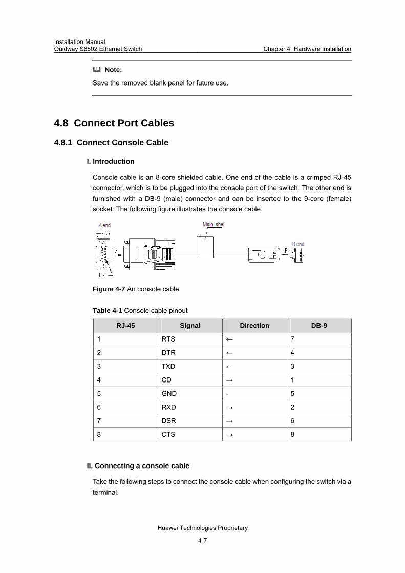
Installation Manual Quidway S6502 Ethernet Switch Chapter 4 Hardware Installation
Huawei Technologies Proprietary
4-7
Note:
Save the removed blank panel for future use.
4.8 Connect Port Cables
4.8.1 Connect Console Cable
I. Introduction
Console cable is an 8-core shielded cable. One end of the cable is a crimped RJ-45 connector, which is to be plugged into the console port of the switch. The other end is furnished with a DB-9 (male) connector and can be inserted to the 9-core (female) socket. The following figure illustrates the console cable.
Figure 4-7 An console cable
Table 4-1 Console cable pinout
RJ-45 Signal Direction DB-9
1 RTS ← 7
2 DTR ← 4
3 TXD ← 3
4 CD → 1
5 GND - 5
6 RXD → 2
7 DSR → 6
8 CTS → 8
II. Connecting a console cable
Take the following steps to connect the console cable when configuring the switch via a terminal.

Installation Manual Quidway S6502 Ethernet Switch Chapter 4 Hardware Installation
Huawei Technologies Proprietary
4-8
Step 1: Plug the DB-9 female plug of the console cable to the serial port of a PC or a terminal where the switch is to be configured.
Step 2: Connect the RJ-45 connector of the console cable to the console port of the switch.
4.8.2 Connect Category-5 Cables
I. Introduction
The 10Base-T/100Base-TX and 1000Base-T ports of an S6502 match RJ-45 connectors, and are MDI/MDIX autosensing. You can use category-5 cables to connect it. The following figure illustrates the appearance and pinouts of an RJ-45 connector.
PIN #8
PIN #1
Figure 4-8 An RJ-45 connector
Table 4-2 RJ-45 MDI port pinout assignment
10Base-T/100Base-TX 1000Base-T Pinout
Signal Function Signal Function
1 Tx+ Outbound BIDA+ Bi-directional data cable A+
2 Tx- Outbound BIDA- Bi-directional data cable A-
3 Rx+ Inbound BIDB+ Bi-directional data cable B+
4 Reserved - BIDC+ Bi-directional data cable C+
5 Reserved - BIDC- Bi-directional data cable C-
6 Rx- Inbound BIDB- Bi-directional data cable B-
7 Reserved - BIDD+ Bi-directional data cable D+
8 Reserved - BIDD- Bi-directional data cable D-
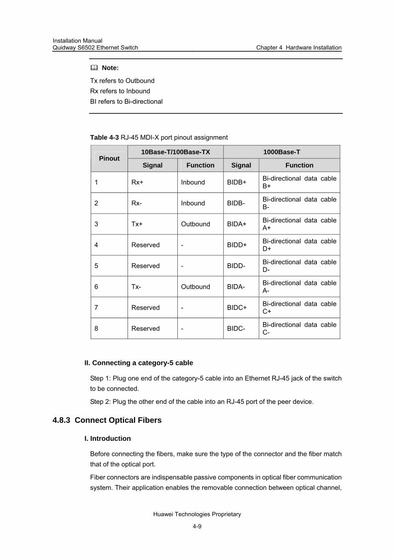
Installation Manual Quidway S6502 Ethernet Switch Chapter 4 Hardware Installation
Huawei Technologies Proprietary
4-9
Note:
Tx refers to Outbound Rx refers to Inbound BI refers to Bi-directional
Table 4-3 RJ-45 MDI-X port pinout assignment
10Base-T/100Base-TX 1000Base-T Pinout
Signal Function Signal Function
1 Rx+ Inbound BIDB+ Bi-directional data cable B+
2 Rx- Inbound BIDB- Bi-directional data cable B-
3 Tx+ Outbound BIDA+ Bi-directional data cable A+
4 Reserved - BIDD+ Bi-directional data cable D+
5 Reserved - BIDD- Bi-directional data cable D-
6 Tx- Outbound BIDA- Bi-directional data cable A-
7 Reserved - BIDC+ Bi-directional data cable C+
8 Reserved - BIDC- Bi-directional data cable C-
II. Connecting a category-5 cable
Step 1: Plug one end of the category-5 cable into an Ethernet RJ-45 jack of the switch to be connected.
Step 2: Plug the other end of the cable into an RJ-45 port of the peer device.
4.8.3 Connect Optical Fibers
I. Introduction
Before connecting the fibers, make sure the type of the connector and the fiber match that of the optical port.
Fiber connectors are indispensable passive components in optical fiber communication system. Their application enables the removable connection between optical channel,
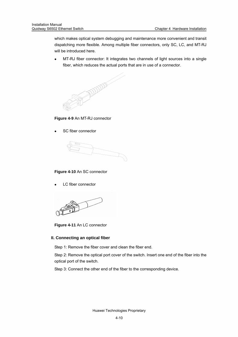
Installation Manual Quidway S6502 Ethernet Switch Chapter 4 Hardware Installation
Huawei Technologies Proprietary
4-10
which makes optical system debugging and maintenance more convenient and transit dispatching more flexible. Among multiple fiber connectors, only SC, LC, and MT-RJ will be introduced here.
MT-RJ fiber connector: It integrates two channels of light sources into a single fiber, which reduces the actual ports that are in use of a connector.
Figure 4-9 An MT-RJ connector
SC fiber connector
Figure 4-10 An SC connector
LC fiber connector
Figure 4-11 An LC connector
II. Connecting an optical fiber
Step 1: Remove the fiber cover and clean the fiber end.
Step 2: Remove the optical port cover of the switch. Insert one end of the fiber into the optical port of the switch.
Step 3: Connect the other end of the fiber to the corresponding device.

Installation Manual Quidway S6502 Ethernet Switch Chapter 4 Hardware Installation
Huawei Technologies Proprietary
4-11
Caution:
When the optical port has not been connected with a fiber connector or its dustproof cover is open, there might be some invisible radiation emitted from the optical port. So do not stare into the optical port directly. Cover the optical port if there is no connector plugged in.
4.9 Recommendations on Cabling
4.9.1 For Table-Mounting
If the chassis of a switch stands alone, you do not have to care about the inside or outside cabinet cabling. All the port service cables can run along the left side of the chassis (cabling channel), and the chassis power cords can run upward or downward based on the specific conditions in the equipment room (lightning protection box, terminal bar etc).
4.9.2 Rack-Mounted Switch
For the switches are mounted in a 19-inch standard rack, the service cables can be bound to the cable binding rack at the left side of the chassis and be arranged to run on the cable rack or in the raised floor according to the situation in an exchange equipment room (whether the signal cable of the room is accessed from the cable rack on the top of the chassis or the cable channel under the floor.) Collect all the transit data signal cable connectors and locate them on the floor of the chassis instead of any places outside the chassis for fear of unexpected damage. The power cords run out of the rear left of the chassis and either on the cable rack or in the raised floor as near as possible based on the specific conditions in the equipment room (lightning protection box, terminal bar etc).
4.10 Cable Binding
4.10.1 Use of Labels
Correctly edit the label and paste it to a proper place on the bound cables.
4.10.2 Precautions for Binding Cables
Bind the cables straight in the cabinet. No twisting or bending.

Installation Manual Quidway S6502 Ethernet Switch Chapter 4 Hardware Installation
Huawei Technologies Proprietary
4-12
Twisting
Bending
Twisting
Bending
Figure 4-12 Cable binding example I
The radius of the curve at which a cable is bent should be no less than twice of the cable’s diameter. At the point where a cable runs out of a connector, the radius of the curve at which the cable is bent should be no less than five times of its diameter.
Cables of different type (that is, power cord, signal cable, ground wire, etc.) should run and be bound separately in a cabinet. They cannot be bound together. If they are close to each other, you can cable them in a crossing way. For parallel cabling, the space between power cord and signal cable should be no less than 30mm;
The cable binding rack and cable channel inside and outside a cabinet should be smooth and stretch no sharp points.
The metal hole through which a cable runs should have a smooth and fully surface or an insulating bush;
Use the right type of ties to bind the cables. Do not bind any cables with tied ties. Huawei technologies provides the following types of ties: 100*2.5mm, 150*3.6mm, 300*3.6mm, 530*9mm, and 580*13mm;
Bind the cables with ties and cut the extra parts. Trim the cut and leave no sharp points. See the following figure:
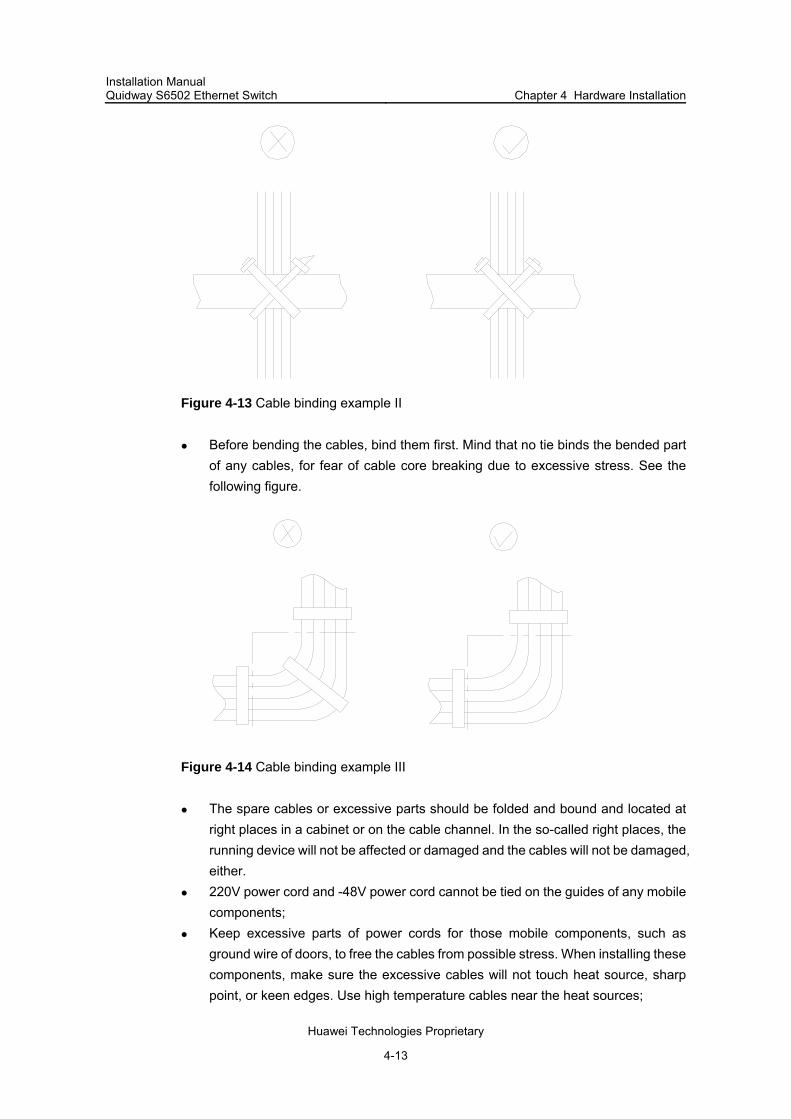
Installation Manual Quidway S6502 Ethernet Switch Chapter 4 Hardware Installation
Huawei Technologies Proprietary
4-13
Figure 4-13 Cable binding example II
Before bending the cables, bind them first. Mind that no tie binds the bended part of any cables, for fear of cable core breaking due to excessive stress. See the following figure.
Figure 4-14 Cable binding example III
The spare cables or excessive parts should be folded and bound and located at right places in a cabinet or on the cable channel. In the so-called right places, the running device will not be affected or damaged and the cables will not be damaged, either.
220V power cord and -48V power cord cannot be tied on the guides of any mobile components;
Keep excessive parts of power cords for those mobile components, such as ground wire of doors, to free the cables from possible stress. When installing these components, make sure the excessive cables will not touch heat source, sharp point, or keen edges. Use high temperature cables near the heat sources;

Installation Manual Quidway S6502 Ethernet Switch Chapter 4 Hardware Installation
Huawei Technologies Proprietary
4-14
For the cable terminals fixed with screw thread, the screws or nuts should be fastened and prevented from loosing. See the following figure;
Flat washer
Flat washer
Spring washer
NutFlat washer
Flat washer
Spring washer
Nut
Figure 4-15 Cable fixing example
Fix the terminal of harder power cords to free the terminal and the cable from stress;
No tapping screw can be used to fasten the cabling terminals; The power cords of the same type and in the same direction should be bound
together and kept clean and straight;
Follow the parameters defined in the following table for binding cables with ties.
Table 4-4 Tie-binding parameters
Cable bundle diameter (mm) Space between bundles (mm)
10 80~150
10~30 150~200
30 200~300
No cable or bundle can tie a knot; The metal parts of crimping cold-pressed terminal blocks (such as air switch)
cannot stretch beyond the blocks.
4.11 Check after Installation

Installation Manual Quidway S6502 Ethernet Switch Chapter 4 Hardware Installation
Huawei Technologies Proprietary
4-15
Caution:
Confirm that you have turned off the power before checking, otherwise, improper connection will hurt people or the component of the switch.
After installing the switch, please check if the items listed in the following table are normal.
Table 4-5 Installation checking list
Items Normal Abnormal (Description)
ESD wrist strap
Console cable
Ground wire
Power cord
SRPU
LPU
Fan Frame

Installation Manual Quidway S6502 Ethernet Switch Chapter 5 System Debugging
Huawei Technologies Proprietary
5-1
Chapter 5 System Debugging
5.1 Setting up Configuration Environment
5.1.1 Setting up Configuration Environment
A terminal (a PC in this example) is connected to the switch console port through a console cable.
PC
Switch
To console port
To serial port
Console cable
Figure 5-1 Configuration environment
5.1.2 Connecting Console Cable
Step 1: Plug the DB-9 female plug of the console cable to the serial port of the PC or the terminal where the switch is to be configured.
Step 2: Connect the RJ-45 connector of the console cable to the console port of the switch.
5.1.3 Setting Terminal Parameters
Parameter requirements:
Bits per second: 9600 Data bits: 8 Parity: none Stop bits: 1 Flow control: none Emulation: VT100
Taking the PC running Windows98 HyperTerminal as an example, this section introduces how to set the terminal parameters.

Installation Manual Quidway S6502 Ethernet Switch Chapter 5 System Debugging
Huawei Technologies Proprietary
5-2
Step 1: Start the PC and run the terminal emulator (such as Terminal on Windows3.1 and the HyperTerminal on Windows95/Windows98/Windows 2000/Windows NT/Windows XP/Windows ME).
Step 2: Set the parameters for Windows98 HyperTerminal as follows:
1) Click Start > Program > Accessories > Communications > HyperTerminal to enter the HyperTerminal window, and then click the Hypertrm icon to establish a new connection. The system will pop up the Connection Description window.
Figure 5-2 Connection description of HyperTerminal
2) Input the name of the new connection and click <OK>. Then there pops up the interface as shown in the following figure. Select the serial port to be used from the Connect using drop down list.

Installation Manual Quidway S6502 Ethernet Switch Chapter 5 System Debugging
Huawei Technologies Proprietary
5-3
Figure 5-3 Setting serial port for HyperTerminal connection
3) After selecting serial ports, click <OK>. The following interface will pop up for setting serial port parameters. Set the baud rate to 9600, data bits to 8, parity check to none, stop bits to 1 and flow control to none.
Figure 5-4 Setting serial port parameters

Installation Manual Quidway S6502 Ethernet Switch Chapter 5 System Debugging
Huawei Technologies Proprietary
5-4
4) After setting serial port parameters, click <OK>. Then the system will enter the HyperTerminal dialogue box as shown in the following figure.
Figure 5-5 HyperTerminal interface
In the above dialogue box, select the Properties icon to enter the properties window. Click Settings to set the attributes (see the following figure). In this interface, select terminal emulation mode VT100 and then click <OK>.
Figure 5-6 Setting terminal emulation mode in the property setting window
Installation Manual Quidway S6502 Ethernet Switch Chapter 5 System Debugging
Huawei Technologies Proprietary
5-5
5.2 Powering on and Booting
5.2.1 Checking before Power on
Before powering on an Ethernet Switch, check that:
The switch has been mounted steadily. All the cards have been correctly installed. All the communication cables, fibers, power cords, and ground wires have been
correctly connected. The voltage of power supply meets the requirements on the switch. The console cable has been correctly connected. The computer or terminal for
configuration has been started and the terminal parameter settings have been done.
Caution:
Before powering on the switch, confirm where the power switch of the equipment room is located, so that you will be able to power off in case of accidence.
5.2.2 Powering on the Switch
Turn on the power supply of the switch. Power on the switch.
5.2.3 Checking after Power on (Recommended)
You are recommended to check as follows after powering on the switch to ensure the configurations thereafter.
After a switch is powered on, the heat dissipation system starts working. You can hear the noise as the fan rotates and feel air flow out from the vent.
Check if any system indicator on the SRPU indicates abnormal condition.
5.2.4 Booting Interface
As the switch is started, the configuration terminal will yield the following output:
Starting......
RAM Line....OK
System is booting................
******************************************
* *
* Quidway S6502 BOOTROM, Version 500 *
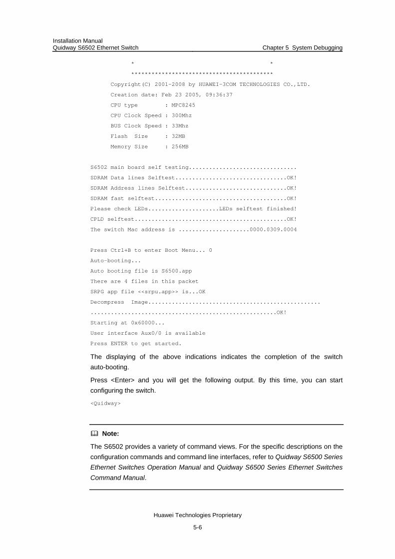
Installation Manual Quidway S6502 Ethernet Switch Chapter 5 System Debugging
Huawei Technologies Proprietary
5-6
* *
******************************************
Copyright(C) 2001-2008 by HUAWEI-3COM TECHNOLOGIES CO.,LTD.
Creation date: Feb 23 2005, 09:36:37
CPU type : MPC8245
CPU Clock Speed : 300Mhz
BUS Clock Speed : 33Mhz
Flash Size : 32MB
Memory Size : 256MB
S6502 main board self testing................................
SDRAM Data lines Selftest.................................OK!
SDRAM Address lines Selftest..............................OK!
SDRAM fast selftest.......................................OK!
Please check LEDs.....................LEDs selftest finished!
CPLD selftest.............................................OK!
The switch Mac address is .....................0000.0309.0004
Press Ctrl+B to enter Boot Menu... 0
Auto-booting...
Auto booting file is S6500.app
There are 4 files in this packet
SRPG app file <<srpu.app>> is...OK
Decompress Image...................................................
.......................................................OK!
Starting at 0x60000...
User interface Aux0/0 is available
Press ENTER to get started.
The displaying of the above indications indicates the completion of the switch auto-booting.
Press <Enter> and you will get the following output. By this time, you can start configuring the switch.
<Quidway>
Note:
The S6502 provides a variety of command views. For the specific descriptions on the configuration commands and command line interfaces, refer to Quidway S6500 Series Ethernet Switches Operation Manual and Quidway S6500 Series Ethernet Switches Command Manual.

Installation Manual Quidway S6502 Ethernet Switch Chapter 6 Switch Monitoring and Maintenance
Huawei Technologies Proprietary
6-1
Chapter 6 Switch Monitoring and Maintenance
6.1 Switch Monitoring
Although the S6502 has passed the comprehensive and strict test before delivery, there might be some fault occurring due to improper installation. This chapter describes how to troubleshoot.
On the SRPU of the S6502, you can find the state LEDs of LPU, power supply, and fan and locate the faults accordingly.
6.1.1 Configuration System Troubleshooting
After the switch is powered on and the system is normal, the booting information will be displayed on the configuration terminal. If the configuration system has failed, the configuration terminal may display illegible characters or nothing at all.
1) No display on the terminal screen
After power on, if there is no information displayed on the terminal, check if:
The power system works normally. SRPU works normally. The console cable has been connected to the console port in the SRPU.
If there is no problem in the above checking, there might be some other faults as follows:
Serial port connected to the console cable is wrong. (The port in use is not the one set on the terminal.)
Configuration terminal parameter setting errors. (Parameter setting requirements: Set the baud rate to 9600, data bits to 8, parity check to none, stop bits to 1, flow control to none, and select VT100 as terminal emulation mode.)
There is something wrong with the console cable. 2) Illegible display on the terminal screen
If the configuration terminal displays illegible characters, the configuration terminal settings are likely to contain errors. Check the settings one by one. (Set the baud rate to 9600, data bits to 8, parity check to none, stop bits to 1, flow control to none, and select VT100 as terminal emulation mode.)
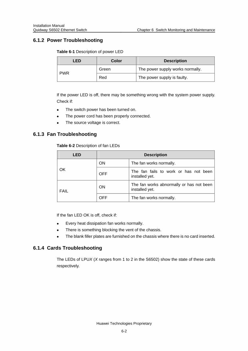
Installation Manual Quidway S6502 Ethernet Switch Chapter 6 Switch Monitoring and Maintenance
Huawei Technologies Proprietary
6-2
6.1.2 Power Troubleshooting
Table 6-1 Description of power LED
LED Color Description
Green The power supply works normally. PWR
Red The power supply is faulty.
If the power LED is off, there may be something wrong with the system power supply. Check if:
The switch power has been turned on. The power cord has been properly connected. The source voltage is correct.
6.1.3 Fan Troubleshooting
Table 6-2 Description of fan LEDs
LED Description
ON The fan works normally. OK
OFF The fan fails to work or has not been installed yet.
ON The fan works abnormally or has not been installed yet. FAIL
OFF The fan works normally.
If the fan LED OK is off, check if:
Every heat dissipation fan works normally. There is something blocking the vent of the chassis. The blank filler plates are furnished on the chassis where there is no card inserted.
6.1.4 Cards Troubleshooting
The LEDs of LPUX (X ranges from 1 to 2 in the S6502) show the state of these cards respectively.

Installation Manual Quidway S6502 Ethernet Switch Chapter 6 Switch Monitoring and Maintenance
Huawei Technologies Proprietary
6-3
Table 6-3 Description of card LEDs
LED Description
ON/OFF The card fails to work or has not been inserted. RUN
Blinking The card works normally.
OFF The card works normally or has not been inserted. ALM
ON The card works abnormally.
If a card ALM LED stays on, there must be something wrong with the corresponding card. When you reset the card, the ALM LED will turn on. After normal booting, it will be off.
When resetting the card, if the ALM LED stays off, the card may have not been connected with the power source. Check if the card has been properly installed.
6.2 Hardware Maintenance
Caution:
The S6502 supports hot-swappable power modules. When installing or replacing a power module with the power on, consider the operation measures and safety with electricity. Do not touch any naked wire, terminal or any part of the product with a dangerous voltage label to avoid hurting human body.
6.2.1 Power Module Replacement
Step 1: Wear the ESD wrist strap and loosen the captive screw in the module to be replaced using the screwdriver.
Step 2: Pull the module to be replaced until it slides out of the slot.
Caution:
Because the S6502 power module is heavy, use both hands to pull it out. Hold the module in one palm and gently pull the handle with the other hand. Install a blank filler panel on the chassis for dust-proof and heat dissipation if you will not install another module in this position.

Installation Manual Quidway S6502 Ethernet Switch Chapter 6 Switch Monitoring and Maintenance
Huawei Technologies Proprietary
6-4
Step 3: Put the removed power module into the package.
Step 4: Take out a new power module from the package and make sure of the input mode.
Step 5: Hold the module in one palm and hold the handle with another hand. Align the module with the guides in the chassis and slide the module gently into the slot. Ensure the module matches well with the guides.
Caution:
Install the power module with caution. Note the direction of the panel. During the process of inserting, if the pin terminal springs up, the system will give an alarm and the pin cannot be seated into the hole. To avoid breaking or cranking the power terminals, if the power module has not been inserted in properly, you should slide it out and insert again.
Step 6: Fasten the captive screws (loosened in Step 1) to fix the power module on the chassis.
Caution:
If the captive screws cannot be fastened, the power module may not have been properly seated. Check it carefully.
6.2.2 Service Card Replacement
SRPU and LPUs of the S6502 can be installed and removed basically in the same way. This section describes the general measures of installing and removing these cards.
Cards of the S6502 are hot-swappable.
I. Required tools
ESD wrist strap Screwdriver
II. Removing service card
Step 1: Wear the ESD wrist strap and loosen the captive screws on the card with Philip screwdriver.

Installation Manual Quidway S6502 Ethernet Switch Chapter 6 Switch Monitoring and Maintenance
Huawei Technologies Proprietary
6-5
Step 2: Hold the ejector levers on the card with both hands and press them toward both sides of you to separate the connectors of the card from the motherboard.
Step 3: Gently slide the card along the guides out of the slot.
Step 4: Put the removed card into the package.
Figure 6-1 Service card removal
III. Installing service card
Step 1: Wear ESD wrist strap and loosen the screws and remove the blank filler panel.
Step 2: Hold the ejector levers of the card with both hands and push them outward, align the card with the guides in the chassis and slide it gently into the slot. Push the card until the positioning pin on its handle bar touches the hole in the chassis.
Step 3: Press the ejector levers inward and seat the pin on the handle bar into the positioning hole in the chassis.
Step 4: Fasten the captive screws to fix the card.
Figure 6-2 Service card installation
6.2.3 Fan Frame Replacement
Caution:
Do not touch any naked wire, terminal or any part of the product with a dangerous voltage label to avoid hurting human body.
I. Required tools
ESD wrist strap Screwdriver

Installation Manual Quidway S6502 Ethernet Switch Chapter 6 Switch Monitoring and Maintenance
Huawei Technologies Proprietary
6-6
II. Replacing fan frame
Step 1: Wear the ESD wrist strap. Loosen the captive installation screws in the fan frame. Hold the fan frame with one hand, and pull the handle of the frame outward with the other, making the fan frame pin disconnected from the backplane.
Caution:
If you want to replace the fan frame of an operating switch, wait till the fan stops rotating before pulling the fan out of the chassis. Since the fan may be still rotating, do not put your hand into the fan frame for fear of hurting.
Step 2: Slide the fan frame gently along the guides of the slot and pull it out.
Step 3: Put the removed fan frame into the package.
Step 4: Hold the fan frame to be installed with one hand at the handle and the other hand at the bottom. Slide it gently along the guide into the slot. Push the fan frame until its positioning pin touches the hole in the chassis.
Step 5: Fasten the captive installation screws.
Caution:
Install a new fan frame soon after removing the old one to ensure that the switch can work normally.
6.3 BOOTROM and Host Software Loading
6.3.1 Introduction to Loading Approaches
This chapter introduces how to load BOOTROM and host software.
You can load the software remotely or locally via commands using:
FTP TFTP
You can load the software locally via Boot Menu using:
XModem via console port TFTP via Ethernet port FTP via Ethernet port

Installation Manual Quidway S6502 Ethernet Switch Chapter 6 Switch Monitoring and Maintenance
Huawei Technologies Proprietary
6-7
Note:
Please note that the BOOTROM version must match the host software version when BOOTROM and host software are being loaded. It is not recommended to load BOOTROM program frequently, BOOTROM program loading is allowed only when the host software to be loaded does not match the existing BOOTROM version.
Using Boot Menu can only load the SRPU BOOTROM program and host software. To load LPU BOOTROM, you must use the command line.
6.3.2 Loading Software Locally via Boot Menu
If your terminal is directly connected to the switch, you can load BOOTROM and host software locally.
Before proceeding to load the software, make sure that your terminal is correctly connected to the switch.
Note:
The steps that you should take to load BOOTROM program and host software are the same, except that in a BOOTROM program loading process you need to press <Ctrl +U> and <Enter> after accessing the BOOTROM menu and will view a different prompt message. BOOTROM loading steps are described below as an example.
I. Boot Menu
After power on, the switch will run BOOTROM program first and the terminal will display the following information:
******************************************
* *
* Quidway S6502 BOOTROM, Version 500 *
* *
******************************************
Copyright(C) 2001-2008 by HUAWEI-3COM TECHNOLOGIES CO.,LTD.
Creation date: Feb 23 2005, 09:36:37
CPU type : MPC8245
CPU Clock Speed : 300Mhz
BUS Clock Speed : 33Mhz
Flash Size : 32MB

Installation Manual Quidway S6502 Ethernet Switch Chapter 6 Switch Monitoring and Maintenance
Huawei Technologies Proprietary
6-8
Memory Size : 256MB
S6502 main board self testing................................
SDRAM Data lines Selftest.................................OK!
SDRAM Address lines Selftest..............................OK!
SDRAM fast selftest.......................................OK!
Please check LEDs.....................LEDs selftest finished!
CPLD selftest.............................................OK!
The switch Mac address is .....................0000.0309.0004
Press Ctrl+B to enter Boot Menu... 5
Press <Ctrl+B> and the system prompts:
Password:
Note:
To access Boot Menu, press <Ctrl+B> within 5 seconds after the screen prompts “Press Ctrl-B to enter Boot Menu...” Otherwise, the system will start executing the program decompression. At this time if you want to access Boot Menu, you will have to reboot the switch. If entering the program decompression process, you will have to wait a long time for the system to get ready, since the program file is rather big in size and many commands needs to be registered in that case.
Enter the BOOTROM password. After entering the correct password (no password is set for the switch by default), the system will access Boot Menu:
Caution:
While using the switch, keep in mind the modified BOOTROM password.
Boot Menu
1: Download application file to flash
2: Select application file to boot
3: Display all files in flash
4: Delete file from flash
5: Modify bootrom password

Installation Manual Quidway S6502 Ethernet Switch Chapter 6 Switch Monitoring and Maintenance
Huawei Technologies Proprietary
6-9
0: Reboot
Enter your choice(0-5):
II. Loading software from console port using XModem
1) Introduction to XModem
XModem is a file transfer protocol widely used due to its simplicity and good functions. XModem transfers files via the console port, supporting data packets of 128 bytes and 1KB. With respect to reliability, it supports checksum, CRC, and error packet retransmission mechanism. Normally, the maximum number of retransmission attempts is ten.
XModem transmission is completed by the receiving program and sending program. The receiving program initiates packet checking method negotiation by sending the negotiation character. If the negotiation passes, the sending program starts packet transmission. Upon the receipt of a complete packet, the receiving program checks it using the agreed-upon checking method. If the check succeeds, the receiving program sends an acknowledgement character; if the check fails, it sends a reject character. Upon the receipt of the acknowledgement, the sending program continues to send the next packet; upon the receipt of the reject, it retransmits the packet.
2) Loading SRPU BOOTROM
Follow these steps to download the BOOTROM program:
Step 1: Press <Ctrl+U> and <Enter> in Boot Menu displayed in the section “I. Boot ” to access the BOOTROM loading menu shown below:
SRPU bootrom update menu:
1. Set TFTP protocol parameter
2. Set FTP protocol parameter
3. Set XMODEM protocol parameter
0. Return to boot menu
Enter your choice(0-3):
Step 2: Enter <3> to download the BOOTROM program using XModem. The system displays the following download speed setting menu:
Please select your download baudrate:
1. 9600
2. 19200
3. 38400
4. 57600
5. 115200*
0. Return
Enter your choice (0-5):5

Installation Manual Quidway S6502 Ethernet Switch Chapter 6 Switch Monitoring and Maintenance
Huawei Technologies Proprietary
6-10
Step 3: Choose an appropriate download baud rate. Type <5> as shown in the above example to choose the baud rate of 115200 bps. Press <Enter>. The system displays the following information:
Are you sure to update your bootrom?(Y/N)
Step 4: The system begins to download if you enter <Y>; it returns to the program downloading menu if you enter <N>. If you enter <Y>, the system displays the following information:
Download baudrate is 115200 bps. Please change the terminal's baudrate to
115200 bps and select XMODEM protocol.
Press enter key when ready.
Note:
You do not need to modify the HyperTerminal’s baud rate if you have chosen 9600 bps, and thus can skip Steps 5 and 6 and proceed to Step 7 directly. At this time, the system will not display the above information.
Step 5: Enter File > Properties in the HyperTerminal window, click <Configure> in the popup dialog box, select the baud rate of 115200bps in the console port configuration dialog box.

Installation Manual Quidway S6502 Ethernet Switch Chapter 6 Switch Monitoring and Maintenance
Huawei Technologies Proprietary
6-11
Figure 6-3 Properties dialog box
Figure 6-4 Console port configuration dialog box

Installation Manual Quidway S6502 Ethernet Switch Chapter 6 Switch Monitoring and Maintenance
Huawei Technologies Proprietary
6-12
Step 6: Click the Disconnect icon to disconnect HyperTerminal from the switch and then click the Connect icon to re-establish the connection using the new baud rate setting.
Figure 6-5 Disconnect and Connect icons
Note:
After changing the baud rate setting, you must disconnect and reconnect the terminal emulation program to validate the new configuration.
Step 7: Press <Enter> to start program loading. The system displays the following information:
Now please start transfer file with XMODEM protocol
If you want to exit, Press <Ctrl+X>
Waiting ... CCCCC
Step 8: Select Transfer > Send File in the HyperTerminal window, and in the popup dialog box similar to the following figure, click <Browse>, select the software you need to download, and set the protocol to XModem.
app
Figure 6-6 Send File dialog box
Step 9: Click <Send>. The system displays the following interface.

Installation Manual Quidway S6502 Ethernet Switch Chapter 6 Switch Monitoring and Maintenance
Huawei Technologies Proprietary
6-13
app
Figure 6-7 Sending file interface
After completing the downloading, the system displays the following information:
Downloading ...CCCCCCCCCCCCCCCCCCCCCCCCCCCCCCCCCCCCCCCCCCCdone!
Are you sure to update SRPU bootrom? Yes or No(Y/N)y
Step 10: Enter <Y> to start file downloading and <N> to return to the program downloading menu. Suppose you enter <Y>. The system starts BOOTROM program downloading and upon its completion automatically starts BOOTROM loading. The system displays the following information upon the completion of the entire process:
SRPU bootrom is updating now......
Get flash Type......FLASH_M29W040B
Erasing flash......done!
Programming flash......done!
Checking flash......done!
SRPU bootrom update menu:
1. Set TFTP protocol parameter
2. Set FTP protocol parameter
3. Set XMODEM protocol parameter
0. Return to boot menu
Enter your choice(0-3):3
Step 11: Enter <3> to return to Boot Menu. Then enter <0> in Boot Menu to reboot the system and the following information will be prompted:
Rebooting...
Please change the terminal's baudrate to 9600 bps!

Installation Manual Quidway S6502 Ethernet Switch Chapter 6 Switch Monitoring and Maintenance
Huawei Technologies Proprietary
6-14
Step 12: Reset HyperTerminal’s baud rate to 9600 bps with reference to Steps 5 and 6 described above.
Note:
You do not need to reset the HyperTerminal’s baud rate and can skip the last step if you have chosen 9600 bps. In this case, the system does not display the prompt message “Please change the terminal's baudrate to 9600 bps!” as shown in Step 11.
3) Loading host software
Follow these steps to download the host software of the switch:
Step 1: Select <1> in Boot Menu. The system displays the following information:
1. Set TFTP protocol parameter
2. Set FTP protocol parameter
3. Set XMODEM protocol parameter
0. Return to boot menu
Enter your choice(0-3):3
The subsequent steps are the same as those for loading BOOTROM, except for the prompt messages.
III. Loading software from Ethernet port using TFTP
1) Introduction to TFTP
Trivial File Transfer Protocol is a TCP/IP protocol used for file transmission between clients and servers. It uses UDP to provide unreliable data stream transfer service.
2) Loading SRPU BOOTROM
Step 1: Connect the switch to the PC from where the file is to be downloaded, via the 10/100Base-TX interface for loading. The IP address of the PC is required. At the same time, the switch is connected to a PC (which can be the same one as that holding the file for downloading) via the console port.
Step 2: Run the TFTP Server program on the PC connected to the Ethernet port, and specify the path for program loading.
Caution:
TFTP Server program is not shipped with the Quidway series switches. When loading BOOTROM and host software, you must use a crossover cable to
connect to the Ethernet port for upgrading.
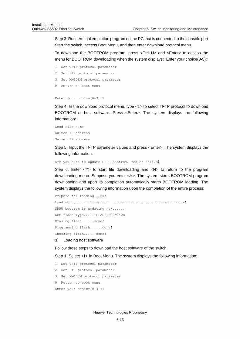
Installation Manual Quidway S6502 Ethernet Switch Chapter 6 Switch Monitoring and Maintenance
Huawei Technologies Proprietary
6-15
Step 3: Run terminal emulation program on the PC that is connected to the console port. Start the switch, access Boot Menu, and then enter download protocol menu.
To download the BOOTROM program, press <Ctrl+U> and <Enter> to access the menu for BOOTROM downloading when the system displays: “Enter your choice(0-5):”
1. Set TFTP protocol parameter
2. Set FTP protocol parameter
3. Set XMODEM protocol parameter
0. Return to boot menu
Enter your choice(0-3):1
Step 4: In the download protocol menu, type <1> to select TFTP protocol to download BOOTROM or host software. Press <Enter>. The system displays the following information:
Load File name
Switch IP address
Server IP address
Step 5: Input the TFTP parameter values and press <Enter>. The system displays the following information:
Are you sure to update SRPU bootrom? Yes or No(Y/N)
Step 6: Enter <Y> to start file downloading and <N> to return to the program downloading menu. Suppose you enter <Y>. The system starts BOOTROM program downloading and upon its completion automatically starts BOOTROM loading. The system displays the following information upon the completion of the entire process:
Prepare for loading...OK!
Loading....................................................done!
SRPU bootrom is updating now......
Get flash Type......FLASH_M29W040B
Erasing flash......done!
Programming flash......done!
Checking flash......done!
3) Loading host software
Follow these steps to download the host software of the switch.
Step 1: Select <1> in Boot Menu. The system displays the following information:
1. Set TFTP protocol parameter
2. Set FTP protocol parameter
3. Set XMODEM protocol parameter
0. Return to boot menu
Enter your choice(0-3):1

Installation Manual Quidway S6502 Ethernet Switch Chapter 6 Switch Monitoring and Maintenance
Huawei Technologies Proprietary
6-16
Select <1>. The subsequent steps are the same as those for loading BOOTROM, except for the displayed prompt messages.
IV. Loading Software from Ethernet Port Using FTP
1) Introduction to FTP
A switch can be used via Ethernet port as an FTP server or a client to provide another approach for software loading and file configuration. An example of a switch being used as an FTP client is given below.
2) Loading SRPU BOOTROM
Step 1: Connect the switch to the PC from where the file is to be downloaded, via the 10/100Base-TX interface on SRPU for loading. The IP address of the PC is required. At the same time, the switch is externally connected to a PC (that can be the same one as that the downloaded file is located) via a console port.
Step 2: Run the FTP Server program on the PC that is connected to the Ethernet port, and specify the path for program loading.
Caution:
FTP Server program is not shipped with the Quidway series switches. When loading BOOTROM and host software, you must use a crossover cable to
connect to the Ethernet port for upgrading.
Step 3: Run terminal emulation program on the PC connected to the console port. Start the switch, access Boot Menu, and then enter download protocol menu.
To download the BOOTROM program, press <Ctrl+U> and <Enter> to access the menu for BOOTROM downloading when the system displays: ”Enter your choice (0-5):”
Enter your choice(0-5):
SRPU bootrom update menu:
1. Set TFTP protocol parameter
2. Set FTP protocol parameter
3. Set XMODEM protocol parameter
0. Return to boot menu
Enter your choice(0-3): 2

Installation Manual Quidway S6502 Ethernet Switch Chapter 6 Switch Monitoring and Maintenance
Huawei Technologies Proprietary
6-17
Step 4: In the download protocol menu, type <2> to select FTP protocol to download BOOTROM and host software. Press <Enter>. The system displays the following information:
Load File name
Switch IP address
Server IP address
FTP User Name
FTP User Password
Step 5: Enter the FTP parameter values. The system displays the following information:
Are you sure to update SRPU bootrom? Yes or No(Y/N)
Step 6: Enter <Y> to start file downloading and <N> to return to the program downloading menu. Suppose you enter <Y>. The system starts program downloading and upon its completion, starts writing to Flash. The system displays the following information after completing the writing operation:
Prepare for loading...OK!
Loading....................................................done!
SRPU bootrom is updating now......
Get flash Type......FLASH_M29W040B
Erasing flash......done!
Programming flash......done!
Checking flash......done!
3) Loading host software
Follow these steps to download the host software:
Step 1: Select <1> in Boot Menu. The system displays the following information:
1. Set TFTP protocol parameter
2. Set FTP protocol parameter
3. Set XMODEM protocol parameter
0. Return to boot menu
Enter your choice(0-3):3
You can select a different protocol to download host software.
The subsequent steps are the same as those for loading the BOOTROM program, except for the displayed prompt messages.
6.3.3 Loading Software Remotely and Locally via Commands
If your terminal is connected to the switch by a network, you can load BOOTROM and host software remotely via commands which can also be used in local software loading.

Installation Manual Quidway S6502 Ethernet Switch Chapter 6 Switch Monitoring and Maintenance
Huawei Technologies Proprietary
6-18
I. Loading by FTP
Run FTP Server on a local PC, provided you have configured username and password and have set the correct file directory. Suppose the IP address of the PC is 10.10.110.1. Log onto the switch via Telnet or the console port, to send the host program to the switch using FTP. Connect the PC and switch with a crossover cable if your terminal is connected to the switch via console port locally.
Note:
The S6502 supports dual image booting, that is, usually the switch boots with the main image (i.e. the primary file), but it uses the backup image (i.e. the backup file) when the primary one is in error. Refer to 6.3.4 Booting the Switch with Dual Images for details. The S6502 also supports the upgrade of combined BOOTROM file, that is, upgrading the BOOTROM of all boards using one combined BOOTROM file. Refer to 6.3.5 Loading Combined BOOTROM File for details.
Suppose that the main boot file is SWITCH002.app; the active host software is SWITCH001.app; the LPU BOOTROM program is LPUbtm.app; LPU occupies slot 3 and SRPU occupies slot 0. You can follow these steps after logging onto the switch.
Step 1: Download the software to the switch using FTP.
<Quidway> ftp 10.10.110.1
Trying ...
Press CTRL+K to abort
Connected.
220 WFTPD 2.0 service (by Texas Imperial Software) ready for new user
User(none):lyt
331 Give me your password, please
Password:
230 Logged in successfully
[ftp] get SWITCH002.app SWITCH002.app
[ftp] get Switchbtm.app Switchbtm.app
[ftp] bye
Note:
You may also download two copies of host software, with one as the primary and the other as the backup.
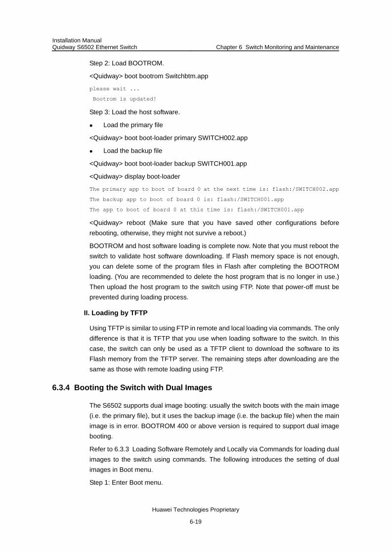
Installation Manual Quidway S6502 Ethernet Switch Chapter 6 Switch Monitoring and Maintenance
Huawei Technologies Proprietary
6-19
Step 2: Load BOOTROM.
<Quidway> boot bootrom Switchbtm.app
please wait ...
Bootrom is updated!
Step 3: Load the host software.
Load the primary file
<Quidway> boot boot-loader primary SWITCH002.app
Load the backup file
<Quidway> boot boot-loader backup SWITCH001.app
<Quidway> display boot-loader
The primary app to boot of board 0 at the next time is: flash:/SWITCH002.app
The backup app to boot of board 0 is: flash:/SWITCH001.app
The app to boot of board 0 at this time is: flash:/SWITCH001.app
<Quidway> reboot (Make sure that you have saved other configurations before rebooting, otherwise, they might not survive a reboot.)
BOOTROM and host software loading is complete now. Note that you must reboot the switch to validate host software downloading. If Flash memory space is not enough, you can delete some of the program files in Flash after completing the BOOTROM loading. (You are recommended to delete the host program that is no longer in use.) Then upload the host program to the switch using FTP. Note that power-off must be prevented during loading process.
II. Loading by TFTP
Using TFTP is similar to using FTP in remote and local loading via commands. The only difference is that it is TFTP that you use when loading software to the switch. In this case, the switch can only be used as a TFTP client to download the software to its Flash memory from the TFTP server. The remaining steps after downloading are the same as those with remote loading using FTP.
6.3.4 Booting the Switch with Dual Images
The S6502 supports dual image booting: usually the switch boots with the main image (i.e. the primary file), but it uses the backup image (i.e. the backup file) when the main image is in error. BOOTROM 400 or above version is required to support dual image booting.
Refer to 6.3.3 Loading Software Remotely and Locally via Commands for loading dual images to the switch using commands. The following introduces the setting of dual images in Boot menu.
Step 1: Enter Boot menu.

Installation Manual Quidway S6502 Ethernet Switch Chapter 6 Switch Monitoring and Maintenance
Huawei Technologies Proprietary
6-20
BOOT MENU
1. Download application file to flash
2. Select application file to boot
3. Display all files in flash
4. Delete file from flash
5. Modify bootrom password
0. Reboot
Enter your choice(0-5): 2
Step 2: Enter <2> to turn to the menu for choosing the active booting file.
File Number File Size(bytes) File Name
========================================================
1. 4 snmpboots
2. 1972 SWITCH100.cfg
3. 1012 taskswitch.log
4. 631736 Btm400.btm
5. 199696 8241btm.app
6. 2427 vrpcfg.txt
7. 6048565 SWITCH200.app
8(*). 5639172 SWITCH000.app
9(-). 203460 SWITCH100.app
The current application file is :SWITCH000.app
The backup application file is : SWITCH100.app
Free Space : 471040 bytes
The system shows all the files in the flash memory, where the one with an asterisk (*) is the primary file and the one with a hyphen (-) is the backup file.
Step 3: Reset the primary and backup files.
Set the primary file.
Enter the serial number of the desired primary file when the terminal shows the following information:
Please input the primary application file number to boot :9
Press <Enter> and the system displays the primary file name you have chosen. Enter <Y> to acknowledge and <N> to reset.
The primary file you selected is SWITCH100.app, are you sure? Yes or No(Y/N):Y
Enter <Y> (as an example) and the terminal shows this information:
On reboot, SWITCH100.app will become the default primary application file to
boot!
This means the primary file has been set successfully.
Set the backup file

Installation Manual Quidway S6502 Ethernet Switch Chapter 6 Switch Monitoring and Maintenance
Huawei Technologies Proprietary
6-21
You can set the backup file in almost the same way as setting the primary file. The terminal shows the following information in this case:
Please input the backup application file number :7
The file you selected is SWITCH200.app, are you sure? Yes or No(Y/N)y
On reboot,SWITCH200.app will become the backup application file to boot!
Step 3: Decide if to run the primary file immediately. Enter <Y> and the system begins to reboot.
Do you want to run SWITCH100.app now?Yes or No(Y/N)?Y
press Ctrl+B to enter Boot Menu... 5
Auto-booting....................
These may occur in your system booting:
1) The primary file is correct and the system boots with the primary file. 2) A fault occurs when the system boots with the primary file, so it boots with the
backup file. 3) Both the primary and backup files are in error, so the system chooses randomly an
application file for booting. 4) The system stops choosing boot file if it fails when booting with a random
application file. Then it just supposes that the file system is unavailable or no correct booting file is available.
Note:
If you specify only the primary file, and set no backup file, the system boots with the primary file. If the primary file is in error, the system randomly chooses an application file for booting.
If you specify only the backup file, and set no primary file, the system boots with the backup file.
If you specify neither the primary file nor the backup file, the system randomly chooses an application file for booting.
6.3.5 Loading Combined BOOTROM File
Since the S6502 supports multiple types of cards of and these cards use different versions of BOOTROM, you are required to use the appropriate BOOTROM file when upgrading the BOOTROM of a card. The upgrading fails if the BOOTROM file does match the card.
To avoid the inconvenience caused by different BOOTROM files in upgrading, in BOOTROM version 400 and the following BOOTROM, we combine the BOOTROM files of all cards (including LPU and SRPU) into one, that is, the BOOTROM released in
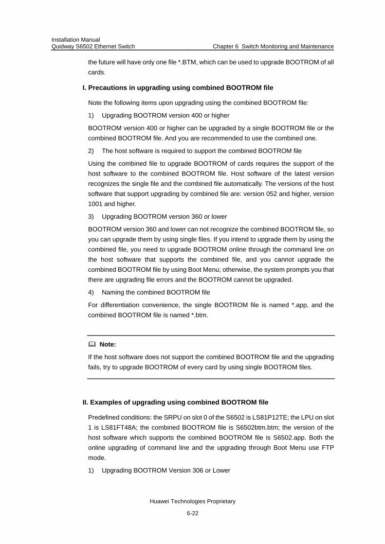
Installation Manual Quidway S6502 Ethernet Switch Chapter 6 Switch Monitoring and Maintenance
Huawei Technologies Proprietary
6-22
the future will have only one file *.BTM, which can be used to upgrade BOOTROM of all cards.
I. Precautions in upgrading using combined BOOTROM file
Note the following items upon upgrading using the combined BOOTROM file:
1) Upgrading BOOTROM version 400 or higher
BOOTROM version 400 or higher can be upgraded by a single BOOTROM file or the combined BOOTROM file. And you are recommended to use the combined one.
2) The host software is required to support the combined BOOTROM file
Using the combined file to upgrade BOOTROM of cards requires the support of the host software to the combined BOOTROM file. Host software of the latest version recognizes the single file and the combined file automatically. The versions of the host software that support upgrading by combined file are: version 052 and higher, version 1001 and higher.
3) Upgrading BOOTROM version 360 or lower
BOOTROM version 360 and lower can not recognize the combined BOOTROM file, so you can upgrade them by using single files. If you intend to upgrade them by using the combined file, you need to upgrade BOOTROM online through the command line on the host software that supports the combined file, and you cannot upgrade the combined BOOTROM file by using Boot Menu; otherwise, the system prompts you that there are upgrading file errors and the BOOTROM cannot be upgraded.
4) Naming the combined BOOTROM file
For differentiation convenience, the single BOOTROM file is named *.app, and the combined BOOTROM file is named *.btm.
Note:
If the host software does not support the combined BOOTROM file and the upgrading fails, try to upgrade BOOTROM of every card by using single BOOTROM files.
II. Examples of upgrading using combined BOOTROM file
Predefined conditions: the SRPU on slot 0 of the S6502 is LS81P12TE; the LPU on slot 1 is LS81FT48A; the combined BOOTROM file is S6502btm.btm; the version of the host software which supports the combined BOOTROM file is S6502.app. Both the online upgrading of command line and the upgrading through Boot Menu use FTP mode.
1) Upgrading BOOTROM Version 306 or Lower

Installation Manual Quidway S6502 Ethernet Switch Chapter 6 Switch Monitoring and Maintenance
Huawei Technologies Proprietary
6-23
Note:
You can use either the command line (see this example) or Boot Menu to upgrade the host software to the version that supports the combined BOOTROM file, and upgrade BOOTROM of all cards using the combined BOOTROM file through command line.
You also can upgrade the BOOTROM of every card by using single BOOTROM files through command line and Boot Menu.
Step 1: Download the host software that supports the combined BOOTROM file and the combined BOOTROM file on the switch using FTP.
<Quidway> ftp 10.10.110.1
[ftp] get S6502.app S6502.app
[ftp] get S6502btm.btm S6502btm.btm
[ftp] bye
Step 2: Specify S6502.app as the application software applied by the switch during the next boot.
<Quidway> boot boot-loader primary S6502.app
Step 3: Reboot the switch to make the S6502.app effective.
<Quidway> reboot
Step 4: Upgrade the BOOTROM of the LPU and SRPU using the combined file.
<Quidway> boot bootrom S6502btm.btm slot 0 1
please wait ...
Bootrom is updated!
After the above operation, you can complete the upgrading of the BOOTROM.
2) Upgrading version 400 or higher
BOOTROM version 400 and higher can recognize the combined BOOTROM file automatically. The host software is also required to support the combined BOOTROM file if you want to upgrade the BOOTROM of all cards.
Online upgrading through command line
The way of upgrading through command line is omitted here since it is the same as that described in the section Upgrading BOOTROM Version 306 or Lower.
Upgrading the combined BOOTROM through Boot Menu
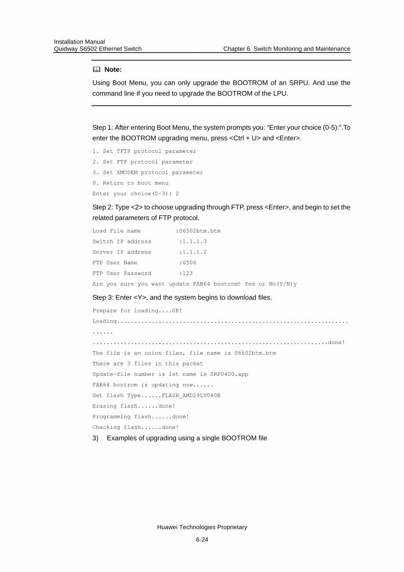
Installation Manual Quidway S6502 Ethernet Switch Chapter 6 Switch Monitoring and Maintenance
Huawei Technologies Proprietary
6-24
Note:
Using Boot Menu, you can only upgrade the BOOTROM of an SRPU. And use the command line if you need to upgrade the BOOTROM of the LPU.
Step 1: After entering Boot Menu, the system prompts you: “Enter your choice (0-5):”.To enter the BOOTROM upgrading menu, press <Ctrl + U> and <Enter>.
1. Set TFTP protocol parameter
2. Set FTP protocol parameter
3. Set XMODEM protocol parameter
0. Return to boot menu
Enter your choice(0-3): 2
Step 2: Type <2> to choose upgrading through FTP, press <Enter>, and begin to set the related parameters of FTP protocol.
Load File name :S6502btm.btm
Switch IP address :1.1.1.3
Server IP address :1.1.1.2
FTP User Name :6506
FTP User Password :123
Are you sure you want update FAB64 bootrom? Yes or No(Y/N)y
Step 3: Enter <Y>, and the system begins to download files.
Prepare for loading....OK!
Loading...................................................................
......
....................................................................done!
The file is an union files, file name is S6502btm.btm
There are 3 files in this packet
Update-file number is 1st name is SRPU400.app
FAB64 bootrom is updating now......
Get flash Type......FLASH_AMD29LV040B
Erasing flash......done!
Programming flash......done!
Checking flash......done!
3) Examples of upgrading using a single BOOTROM file

Installation Manual Quidway S6502 Ethernet Switch Chapter 6 Switch Monitoring and Maintenance
Huawei Technologies Proprietary
6-25
Caution:
Ensure to use the appropriate version of BOOTROM file during upgrading the BOOTROM of every card by single BOOTROM files; otherwise, the switch crashes.
You can choose either the command line or Boot Menu mode to upgrade by using single BOOTROM file. You are recommended to use the command line mode to complete the online upgrading. Here takes the command line mode as an example.
Predefined conditions: the card on slot 0 of the S6502 is LS81SRPUA, and its corresponding BOOTROM file is SRPUbtm.app; the card LS81FT48A is on slot 1, and its corresponding BOOTROM file is LPUbtm.app. This example introduces online upgrading through FTP mode; you can also upgrade BOOTROM through the TFTP mode, which is omitted here.
Follow these steps to upgrade:
Step 1: Download single BOOTROM file to the switch through FTP.
<Quidway> ftp 10.10.110.1
[ftp] get SRPUbtm.app SRPUbtm.app
[ftp] get LPUbtm.app LPUbtm.app
[ftp] bye
Step 2: Load single BOOTROM files to every card.
<Quidway> boot bootrom SRPUbtm.app slot 0
<Quidway> boot bootrom LPUbtm.app slot 1
After the above operation, you can complete the upgrading of the BOOTROM on every card.
6.3.6 Dealing with Failed Loading
If loading fails, the original version will remain in the system.
In this case, check that the physical ports are correctly and well connected. If they are not, reconnect them correctly and restart loading procedures.
If there are no problems with the physical connections, carefully check information about the loading procedures for input errors on the HyperTerminal.
When using XModem, check that you have reset the baud rate of the HyperTerminal to 9600bps after loading the software with a baud rate other than 9600 bps;
1) When using TFTP, check that you have provided: Correct server and switch IP addresses; Correct name of the software to be loaded;

Installation Manual Quidway S6502 Ethernet Switch Chapter 6 Switch Monitoring and Maintenance
Huawei Technologies Proprietary
6-26
Correct path for TFTP Server to operate. 2) When using FTP, check that you have provided:
Correct server and switch IP addresses; Correct name of the software to be loaded; Correct username and password.
If loading fails when there are neither physical connection problems nor input errors, contact the local agents of Huawei Technologies for help.
6.3.7 Dealing with Lost Password
Please contact the local agent of Huawei Technologies if the BOOTROM password or user password of the switch is lost.
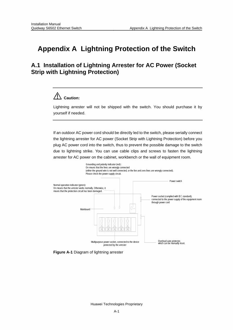
Installation Manual Quidway S6502 Ethernet Switch Appendix A Lightning Protection of the Switch
Huawei Technologies Proprietary
A-1
Appendix A Lightning Protection of the Switch
A.1 Installation of Lightning Arrester for AC Power (Socket Strip with Lightning Protection)
Caution:
Lightning arrester will not be shipped with the switch. You should purchase it by yourself if needed.
If an outdoor AC power cord should be directly led to the switch, please serially connect the lightning arrester for AC power (Socket Strip with Lightning Protection) before you plug AC power cord into the switch, thus to prevent the possible damage to the switch due to lightning strike. You can use cable clips and screws to fasten the lightning arrester for AC power on the cabinet, workbench or the wall of equipment room.
Mainboard
Grounding and polarity indicator (red) :On means that the lines are wrongly connected(either the ground wire is not well connected, or the live and zero lines are wrongly connected).Please check the power supply circuit.
Power switchNormal operation indicator (green): On means that the arrester works normally. Otherwise, it means that the protection circuit has been damaged.
Multipurpose power socket, connected to the deviceprotected by the arrester
Power socket (complied with IEC standard), connected to the power supply of the equipment roomthrough power cord
Overload auto protector,which can be manually reset.
Figure A-1 Diagram of lightning arrester

Installation Manual Quidway S6502 Ethernet Switch Appendix A Lightning Protection of the Switch
Huawei Technologies Proprietary
A-2
Caution:
Make sure that the arrester is well grounded before using the lightning arrester for power.
After inserting AC power cord plug of switch into the socket of lightning arrester, if the green LED is on and the red LED does not alarm, it means that the lightning arrester of power is running and the function of lightning protection has taken effect.
Pay adequate attention if the red LED is on. You should correctly locate the problem, whether it is caused because the ground wire of the arrester is not well grounded or because the live and zero wires are connected in reverse direction. You may check that in the following way. When the red LED is on, use a multimeter to examine polarity at the power socket of the arrester. If it is same to that of the power socket in the equipment room, it means that arrester is not well grounded. If it is adverse to that of the power socket in the equipment room, it means that the power socket of the arrester is set to the reverse polarity. In this case, you should open the power socket of arrester to correct polarity. After that, if the red LED still alarms, it means that the arrester is not well grounded yet.
A.2 Installation of Lightning Arrester for Network Port
Note:
Lightning arrester for network port is specially designed for the Ethernet port of 10/100M electrical interface (RJ-45 connector is adopted in this case).
Caution:
Lightning arrester for network port will not be provided along with the switch, and you should purchase it by yourself if needed.
6If an outdoor network cable should be led to the switch, please serially connect the lightning arrester for network port before you plug this cable into the interface on the switch, in case of the possibility that the switch may be damaged due to lightning strike.
I. Required tools
Phillips screwdriver or Flat-blade screwdriver

Installation Manual Quidway S6502 Ethernet Switch Appendix A Lightning Protection of the Switch
Huawei Technologies Proprietary
A-3
Multimeter Tilted wire cutter
II. Installation procedure
Step 1: Tear the protection paper at one side of the double faced adhesive tape apart from the tape, and stick the tape on the surface of the arrester. Tear the protection paper at another side apart from the tape, and stick the arrester onto the chassis of the switch. The arrester should be attached on the chassis as close to the grounding screw as possible.
Step 2: According to the distance to the grounding screw of the switch, cut the ground wire of the arrester, and securely tightening its ground wire to the grounding screw of the switch.
Step 3: Use the multimeter to measure whether the ground wire of the arrester contacts well with the grounding screw of chassis.
Step 4: According to the instruction of arrester for network port, connect the arrester with switch by the cables (be carefully with the cable direction. Outdoor network cable should be inserted into the arrester‘s IN end, and the cable connected to the switch should be inserted into the arrester’s OUT end). When you do that, observe whether the arrester indicators normally display.
Note:
The instruction of lightning arrester for network port contains the technical specifications, installation and maintenance guide of the arrester. Please carefully read it before installing the arrester.
Step 5: Use the nylon ties to bundle the cables neatly.
Switch
Network cable indoors
Power input
Network cable led into from outdoor
Lightning arrester for network port(attached onto the chassis)
Ground wire of lightning arrester
Grounding screw of switch
Metal cabinet that contains the switch
Figure A-2 Installation diagram of lightning arrester for network port

Installation Manual Quidway S6502 Ethernet Switch Appendix A Lightning Protection of the Switch
Huawei Technologies Proprietary
A-4
III. Installation precautions
Fully consider the following items in the installation process, otherwise, the performance of the lightning arrester for network port will be affected:
Lightning arrester for network port is installed in reverse direction. In practice, the “IN” end should be connected to the outdoor network cable and the “OUT” end to the network port on the switch.
Lightning arrester for the network port is not well grounded. The ground wire for the arrester should be as short as possible, so to ensure its good contact with the grounding screw of the switch. After the connection, use the multimeter to confirm that.
The lightning arrester for the network port is not installed completely. If the switch has more than one network ports to interconnect with other devices via cables outdoor, you should install lightning arresters for all these network ports for protection.


![Quidway S9300 Series Terabit Routing Switch Brochure[1]](https://static.fdocuments.net/doc/165x107/55142e6a497959071e8b45ba/quidway-s9300-series-terabit-routing-switch-brochure1.jpg)