449 Series - ASCO Asset Library/numatics-series-449-compact... · *SentronicD Proportional Valves,...
24
449 Series Compact Cylinder to ISO 21287 www.asco.com
Transcript of 449 Series - ASCO Asset Library/numatics-series-449-compact... · *SentronicD Proportional Valves,...
449 SeriesCompact Cylinder to ISO 21287
www.asco.com

Today Numatics is proud to be a part of Emerson Electric Co. Emerson (NYSE:EMR), based in St. Louis, Missouri (USA), is a global leader in bringing technol-ogy and engineering together to provide innovative solutions for customers in industrial, com-mercial, and consumer markets through its network power, pro-cess management, industrial auto-mation, climate technologies, and appliance and tools businesses. For more information, visit www.Emerson.com.
Numatics, Inc. is a leading manufacturer of pneumatic products and motion control products. Our broad spectrum of standard, custom developed products and application components, have made a significant impact on pneumatic innovation as well as pneumatic and motion control technology. Our company has an extensive history of generating innovative concepts and technological breakthroughs. Many of today’s standard features in pneumatic technology were industry firsts from Numatics. We continue our innovative approach to product development by developing electric motion control solutions and enhancing our embedded Fieldbus and I/O products to continually meet and solve our customer’s application requirements.
i
We are committed to providing you with an unmatched level of customer service, quality, and reliability. If you cannot locate the specific product for your application or need additional product specifications, visit www.numatics.com or call 888-686-2842. Numatics Express orders cannot be canceled or adjusted once entered. Saturdays, Sundays, and Holidays are excluded.
†As industry requirements change, Numatics reserves the right to modify the contents of this catalog and program without notification. Updates on this program can be obtained from the Numatics website www.numatics.com or by calling 888-686-2842, or by contacting your local Numatics representative or distributor and referencing the Numatics Express program.
*SentronicD Proportional Valves, CGT Compact Slides, NR Series Rodless and Air Bellows are limited to orders up to 5.
**A Series Large Bore NFPA, ASP Series Steel Body NFPA and G Series Guide Rail Rodless are limited to orders up to 5.
Numatics Express Shipping Program guarantees† product shipment in two, three or five business days. Unlike most
traditional quick ship programs, the Numatics Express Shipping Program includes the most comprehensive offering in the industry. This program encompasses the range and options that you require!
Numatics is committed to offering you the highest level of customer service, quality and performance.
Numatics Express 2Day shipping program guarantees† product shipment in two business days. The program includes the most popular valve, air preparation and actuator products and includes applicable switches and mounting accessories.
Numatics guarantees† to ship any order received before 3 pm EST for up to 10 2Day products* in two business days.
Numatics Express shipping program offers a 3Day shipping program that guarantees† product shipment of a fully assembled and tested valve manifold in 3 business days. The program includes the most popular manifold configurations of the 2000 and Mark series valves:• Sub D, Terminal Strip and Fieldbus Electronic Options• Can be configured for DIN Rail Mounting and Muffled Exhaust• Shipped complete and 100% tested
The 3Day Express shipping program enables you to create a 2 to 8 station manifold assembly complete with any combination of valves, regulators, and blank stations that can be configured from the valve model charts in this catalog.
Numatics guarantees† to ship any order received before 3 pm EST for up to 5 manifold assemblies configured from this catalog in three business days or Numatics pays the shipping cost.
We are pleased to expand Numatics Express to include a broad range of products in a 5Day shipping program. Numatics guarantees† to ship up to 10 of any 5Day product** for orders received before 3 pm EST in 5 business days or Numatics pays the shipping cost.
ii
Since 1945, Numatics has emerged as the prominent specialist in developing and manufacturing pneumatic and fluid power compo-nents for a widely diverse field of automated industry. From idea to implementation, leading engineers choose Numatics as their single source for: • Quality Fluid Power components • Technologically advanced design resources • Quick response time in delivery and service from around the world
Welcome to the World of Fluid Automation...
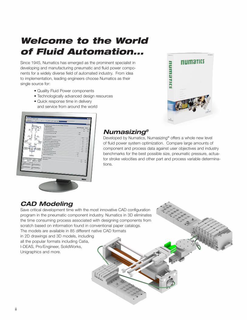
CAD Modeling Save critical development time with the most innovative CAD configuration program in the pneumatic component industry. Numatics in 3D eliminates the time consuming process associated with designing components from scratch based on information found in conventional paper catalogs. The models are available in 85 different native CAD formats in 2D drawings and 3D models, including all the popular formats including Catia, I-DEAS, Pro/Engineer, SolidWorks, Unigraphics and more.
Numasizing® Developed by Numatics, Numasizing® offers a whole new level of fluid power system optimization. Compare large amounts of component and process data against user objectives and industry benchmarks for the best possible size, pneumatic pressure, actua-tor stroke velocities and other part and process variable determina-tions.

1
Table of Contents
Series 449 Features and Benefits 2 How to Order 3 Single and Double Rod Dimensions 4-5 Cylinder Standard Mount Information 6-13 Sensor Information 14-16
Information subject to change without notice. For ordering information or regarding your local sales office, please visit www.asco.com.2
ISO 21287 Cylinder449 SERIES
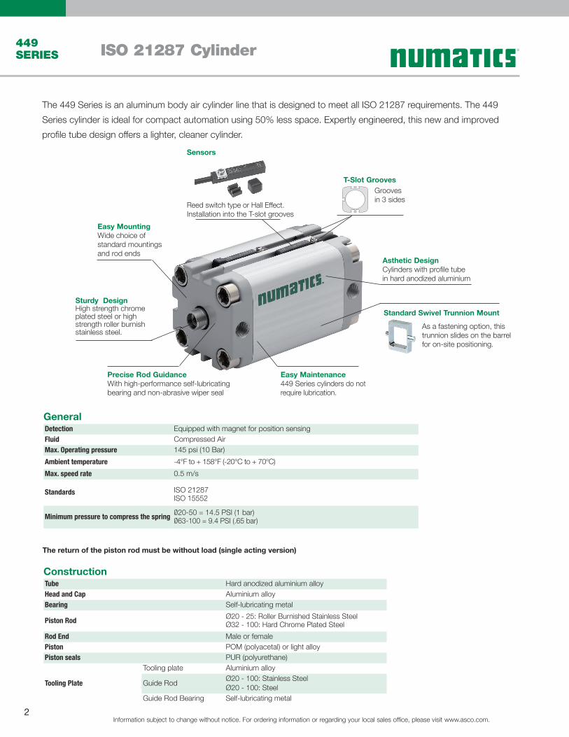
Asthetic DesignCylinders with profile tube in hard anodized aluminium
Easy MountingWide choice of standard mountings and rod ends
Sturdy DesignHigh strength chrome plated steel or high strength roller burnish stainless steel.
Precise Rod GuidanceWith high-performance self-lubricating bearing and non-abrasive wiper seal
Easy Maintenance449 Series cylinders do not require lubrication.
T-Slot GroovesGrooves in 3 sides
Reed switch type or Hall Effect. Installation into the T-slot grooves
Sensors
Standard Swivel Trunnion Mount
As a fastening option, this trunnion slides on the barrel for on-site positioning.
Construction
General
Tube Hard anodized aluminium alloyHead and Cap Aluminium alloyBearing Self-lubricating metal
Piston Rod Ø20 - 25: Roller Burnished Stainless SteelØ32 - 100: Hard Chrome Plated Steel
Rod End Male or femalePiston POM (polyacetal) or light alloyPiston seals PUR (polyurethane)
Tooling Plate
Tooling plate Aluminium alloy
Guide Rod Ø20 - 100: Stainless SteelØ20 - 100: Steel
Guide Rod Bearing Self-lubricating metal
Detection Equipped with magnet for position sensingFluid Compressed AirMax. Operating pressure 145 psi (10 Bar)Ambient temperature -4°F to + 158°F (-20°C to + 70°C)Max. speed rate 0.5 m/s
Standards ISO 21287 ISO 15552
Minimum pressure to compress the spring Ø20-50 = 14.5 PSI (1 bar) Ø63-100 = 9.4 PSI (.65 bar)
The 449 Series is an aluminum body air cylinder line that is designed to meet all ISO 21287 requirements. The 449 Series cylinder is ideal for compact automation using 50% less space. Expertly engineered, this new and improved profile tube design offers a lighter, cleaner cylinder.
The return of the piston rod must be without load (single acting version)
Information subject to change without notice. For ordering information or regarding your local sales office, please visit www.asco.com.3
ISO 21287 Cylinder 449 SERIES
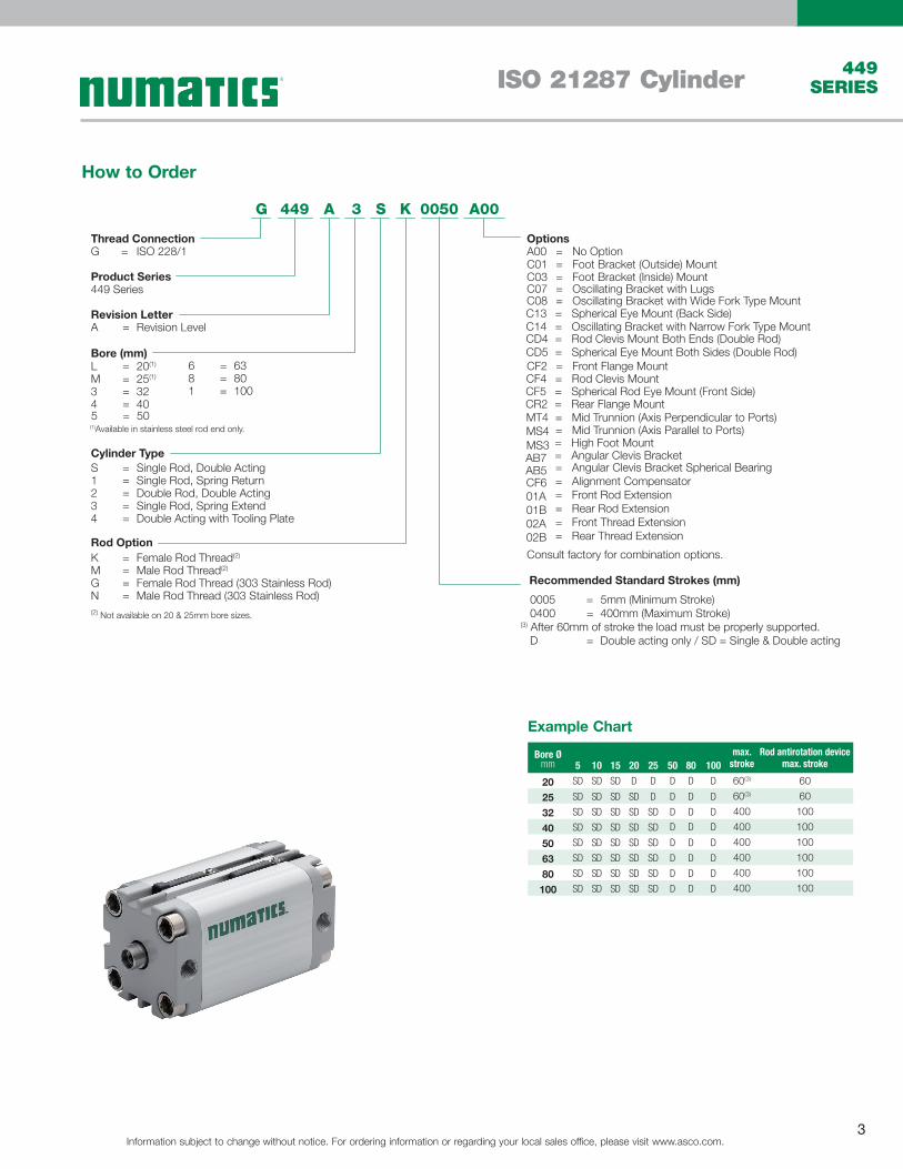
A00G 449
Thread ConnectionG ISO 228/1=
Product Series449 Series
Revision LetterA = Revision Level
Bore (mm)
4 = 403 = 32
6 = 63
5 = 50
1 = 100
(1)Available in stainless steel rod end only.
8 = 80
1 = Single Rod, Spring Return
Cylinder TypeS = Single Rod, Double Acting
(2) Not available on 20 & 25mm bore sizes.
3 = Single Rod, Spring Extend2 = Double Rod, Double Acting
4 = Double Acting with Tooling Plate
M = Male Rod Thread(2)
Rod OptionK = Female Rod Thread(2)
N = Male Rod Thread (303 Stainless Rod)G = Female Rod Thread (303 Stainless Rod)
OptionsA00 = No OptionC01 = Foot Bracket (Outside) MountC03 = Foot Bracket (Inside) MountC07 = Oscillating Bracket with LugsC08 = Oscillating Bracket with Wide Fork Type MountC13 = Spherical Eye Mount (Back Side)C14 = Oscillating Bracket with Narrow Fork Type MountCD4 = Rod Clevis Mount Both Ends (Double Rod)
Consult factory for combination options.
0005 = 5mm (Minimum Stroke) 0400 = 400mm (Maximum Stroke)(3) After 60mm of stroke the load must be properly supported. D = Double acting only / SD = Single & Double acting
Recommended Standard Strokes (mm)
A 3 S K 0050
CD5 = Spherical Eye Mount Both Sides (Double Rod)CF2 = Front Flange MountCF4 = Rod Clevis MountCF5 = Spherical Rod Eye Mount (Front Side)CR2 = Rear Flange MountMT4MS4
= Mid Trunnion (Axis Perpendicular to Ports)
MS3= Mid Trunnion (Axis Parallel to Ports)
AB7= High Foot Mount
AB5= Angular Clevis Bracket
CF601A01B02A02B
======
Angular Clevis Bracket Spherical BearingAlignment CompensatorFront Rod ExtensionRear Rod ExtensionFront Thread ExtensionRear Thread Extension
M = 25(1)L = 20(1)
How to Order
Bore Ømm
max. stroke
Rod antirotation device max. stroke5 10 15 20 25 50 80 100
20 SD SD SD D D D D D 60(3) 6025 SD SD SD SD D D D D 60(3) 6032 SD SD SD SD SD D D D 400 10040 SD SD SD SD SD D D D 400 10050 SD SD SD SD SD D D D 400 10063 SD SD SD SD SD D D D 400 10080 SD SD SD SD SD D D D 400 100100 SD SD SD SD SD D D D 400 100
Example Chart
Information subject to change without notice. For ordering information or regarding your local sales office, please visit www.asco.com.4
ISO 21287 Cylinder449 SERIES
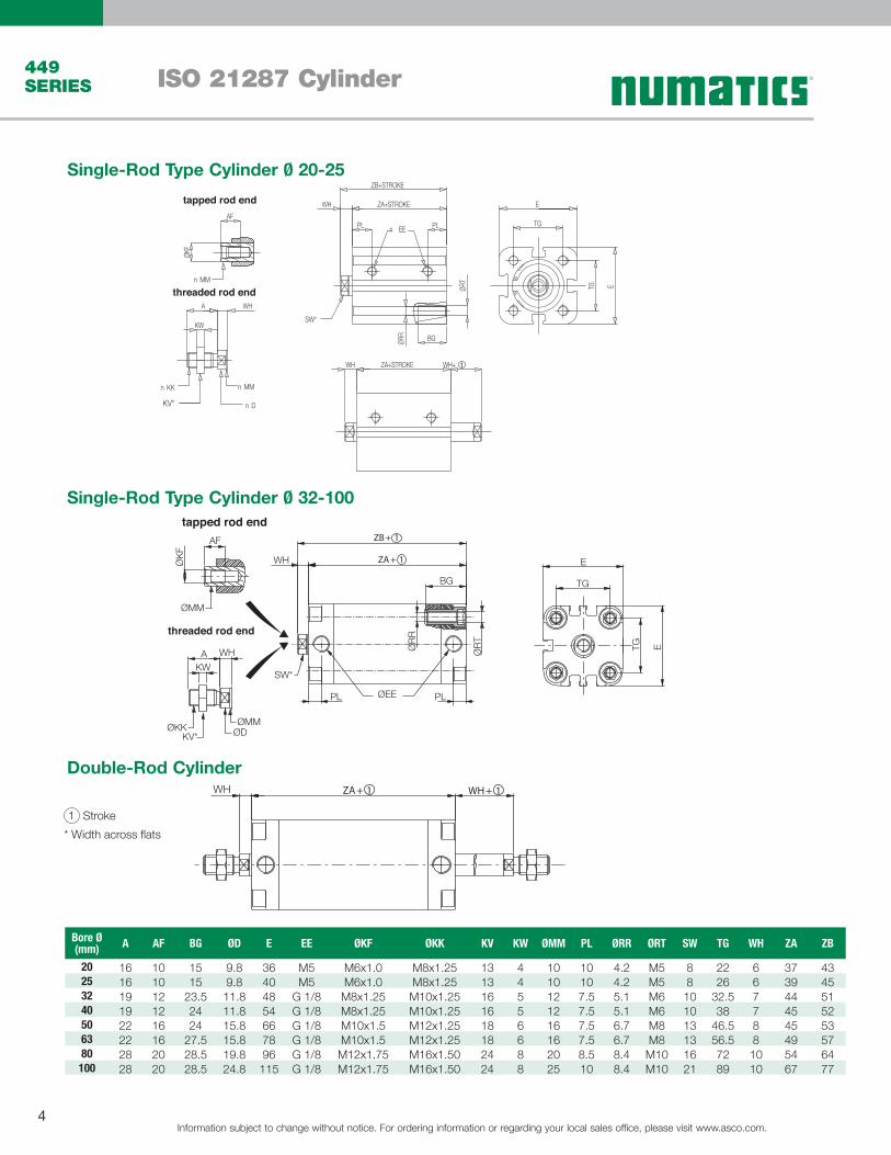
Single-Rod Type Cylinder Ø 20-25
Single-Rod Type Cylinder Ø 32-100
Double-Rod Cylinder
B
C
D
ZA+STROKE
ZB+STROKE
PL
WH E
TG
ETG
BG
PL
WH ZA+STROKE WH+
A
KW
WH
AF
ØKF
ØRR
ØRT
n EE
n KK
KV* n D
n MM
n MM
SW*
tapped rod end
threaded rod end
threaded rod end
tapped rod end
WH
BG
SW*
PL PLØEE
ØR
R
ØR
T
AF
ØMM
ØK
F
A WH
KW
ØKKKV*
ØMMØD
E
TG
ETG
WH 1 Stroke* Width across flats
Bore Ø (mm) A AF BG ØD E EE ØKF ØKK KV KW ØMM PL ØRR ØRT SW TG WH ZA ZB
20 16 10 15 9.8 36 M5 M6x1.0 M8x1.25 13 4 10 10 4.2 M5 8 22 6 37 4325 16 10 15 9.8 40 M5 M6x1.0 M8x1.25 13 4 10 10 4.2 M5 8 26 6 39 4532 19 12 23.5 11.8 48 G 1/8 M8x1.25 M10x1.25 16 5 12 7.5 5.1 M6 10 32.5 7 44 5140 19 12 24 11.8 54 G 1/8 M8x1.25 M10x1.25 16 5 12 7.5 5.1 M6 10 38 7 45 5250 22 16 24 15.8 66 G 1/8 M10x1.5 M12x1.25 18 6 16 7.5 6.7 M8 13 46.5 8 45 5363 22 16 27.5 15.8 78 G 1/8 M10x1.5 M12x1.25 18 6 16 7.5 6.7 M8 13 56.5 8 49 5780 28 20 28.5 19.8 96 G 1/8 M12x1.75 M16x1.50 24 8 20 8.5 8.4 M10 16 72 10 54 64100 28 20 28.5 24.8 115 G 1/8 M12x1.75 M16x1.50 24 8 25 10 8.4 M10 21 89 10 67 77
WH
BG
SW*
PL PLØEE
ØR
R
ØR
T
AF
ØMM
ØK
F
A WH
KW
ØKKKV*
ØMMØD
E
TG
ETG
WH
Information subject to change without notice. For ordering information or regarding your local sales office, please visit www.asco.com.5
ISO 21287 Cylinder 449 SERIES
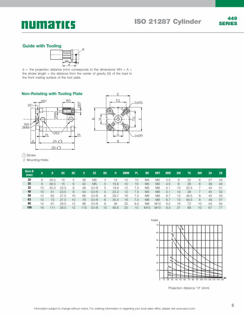
Non-Rotating with Tooling Plate
Fd
G
WH A
d = the projection distance (mm) corresponds to the dimensions WH + A + the stroke length + the distance from the center of gravity (G) of the load to the front mating surface of the tool plate.
Projection distance "d" (imm)
10
100 20 30 40 50 60 70 80 90 100 110 120 130 140 150
20
30
40
50
60
70
F(daN)
Ø100
Ø80Ø63
Ø50Ø40
Ø32
Ø25Ø20
1 Stroke 2 Mounting Holes
Bore Ø (mm) A B BG ØC E EE ØG H ØMM PL ØR ØRT ØRR SW TG WH ZA ZB
20 8 30.5 15 5 36 M5 4 12 10 10 M4 M5 4.5 8 22 6 37 4325 8 36.5 15 6 40 M5 5 15.6 10 10 M5 M5 4.5 8 26 6 39 4532 10 45.3 23.5 8 48 G1/8 5 19.8 12 7.5 M5 M6 5.1 10 32.5 7 44 5140 10 51 23.5 8 54 G1/8 5 23.3 12 7.5 M5 M6 5.1 10 38 7 45 5250 12 62 27.5 10 66 G1/8 6 29.7 16 7.5 M6 M8 6.7 13 46.5 8 45 5363 12 73 27.5 10 78 G1/8 6 35.4 16 7.5 M6 M8 6.7 13 56.5 8 49 5780 14 91 28.5 12 96 G1/8 8 46 20 8.5 M8 M10 8.5 16 72 10 54 64100 16 111 28.5 12 115 G1/8 10 56.6 25 10 M10 M10 8.5 21 89 10 67 77
Guide with Tooling
WHØC
BG
ØR
T
ØR
R
SWØMM
PL
A
ØEE
ZA + 1
ZB + 1
PL
E
TG2xØG
B H TG E
H
B
2xØR
Information subject to change without notice. For ordering information or regarding your local sales office, please visit www.asco.com.6
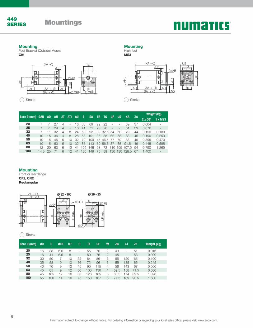
Mountings449 SERIES
XA + 1
ZA + 1SA + 1
AT12øAB
AUAO
AT1
AU
AH
USTG= =
= =
UF
TR= == == =
= =XA + 1
AT
2øAB
AT
ZA + 1SA + 1
AUAU
AH
AO
TG
TRE
ZF + 1ZB + 1
WMF
E = =
ØDH11R= = 4Ø FB
UF
TF
E = =
ØDH11
2Ø FB
UF
TF
MountingFoot Bracket (Outside) Mount C01
MountingHigh footMS3
1 Stroke
Bore Ø (mm) ØAB AO AH AT AT1 AU E SA TR TG UF US XA ZAWeight (kg)
2 x C01 1 x MS320 7 7 27 4 - 16 38 69 22 22 - - 59 37 0.064 -25 7 7 29 4 - 16 41 71 26 26 - - 61 39 0.076 -32 7 11 32 4 8 24 50 92 32 32.5 54 50 79 44 0.150 0.18040 10 15 36 4 8 28 58 101 36 38 62 58 83 45 0.190 0.25050 10 15 45 5 10 32 70 109 45 46.5 77 70 88 45 0.395 0.47063 10 15 50 5 10 32 85 113 50 56.5 87 85 91.5 49 0.445 0.59580 12 20 63 6 12 41 105 146 63 72 110 105 107.5 54 0.790 1.265100 14.5 25 71 6 12 41 130 149 75 89 130 130 128.5 67 1.400 -
Bore Ø (mm) ØD E ØFB MF R TF UF W ZB ZJ ZF Weight (kg)
20 16 38 6.6 8 - 55 70 2 43 - 51 0.01625 16 41 6.6 8 - 60 76 2 45 - 53 0.02032 30 50 7 10 32 64 86 3 55 120 65 0.19040 35 58 9 10 36 72 96 3 55 135 65 0.24550 40 70 9 12 45 90 115 4 56 143 67 0.50063 45 85 9 12 50 100 130 4 59.5 158 71.5 0.58080 45 105 12 16 63 126 165 6 66.5 174 82.5 1.390100 55 130 14 16 75 150 187 6 77.5 189 93.5 1.630
1 Stroke
1 Stroke
max.
max. max.
max.max.
max
.
max
.
Ø 32 - 100 Ø 20 - 25
MountingFront or rear flangeCF2, CR2Rectangular
Information subject to change without notice. For ordering information or regarding your local sales office, please visit www.asco.com.7
Mountings 449 SERIES
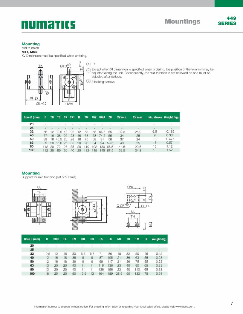
MountingMid trunnionMT4, MS4XV Dimension must be specified when ordering.
1 XI
2 Except when XI dimension is specified when ordering, the position of the trunnion may be adjusted along the unit. Consequently, the mid trunnion is not screwed on and must be adjusted after delivery.
3 8 locking screws
MountingSupport for mid trunnion (set of 2 items)
A
XV 2
ZJ + 1
TK
3 3
ØTDe9
TMh1
4TL
h14
EUWA
TG=== == =
TK
XI 2
ZB + 1
Bore Ø (mm) E TD TG TK TK1 TL TM UW UWA ZB XV min. XV max. min. stroke Weight (kg)
20 - - - - - - - - - - - - - -25 - - - - - - - - - - - - - -32 56 12 32.5 18 22 12 53 55 64.5 55 32.3 25.9 6.5 0.18540 67 16 38 20 28 16 63 58 74.5 55 34 25 9 0.3350 89 16 46.5 20 28 16 75 68 91 56 37 24 13 0.47563 89 20 56.6 25 35 20 90 84 94 59.5 40 25 15 0.5780 112 20 72 25 35 20 110 102 130 66.5 44.5 29.5 15 1.12100 112 25 89 30 40 25 132 145 145 87.5 52.5 34.8 18 1.52
TMh1
4
L5 L6
==
==
== TH==
UL
NH
FN
H3Ød4
Ø HBØ CRH9
C
==
= =
FK
= == =
UL
TH= == =
UL
TH= == =
UL
TH
TMh1
4
L5 L6
==
==
== TH==
UL
NH
FN
H3Ød4
Ø HBØ CRH9
C
==
= =
FK= =
= =UL
TH= == =
UL
TH= == =
UL
TH
Series 453 Series 450Series 449Bore Ø (mm) C ØCR FK FN HB H3 L5 L6 NH TH TM UL Weight (kg)
20 - - - - - - - - - - - - -25 - - - - - - - - - - - - -32 10.5 12 15 30 6.6 6.8 71 86 18 32 50 46 0.1240 12 16 18 36 9 9 87 105 21 36 63 55 0.2350 12 16 18 36 9 9 99 117 21 36 75 55 0.2363 13 20 20 40 11 11 116 136 23 40 90 65 0.3380 13 20 20 40 11 11 136 156 23 40 110 65 0.33100 16 25 25 50 13.5 13 164 189 28.5 50 132 75 0.58
Information subject to change without notice. For ordering information or regarding your local sales office, please visit www.asco.com.8
Mountings449 SERIES
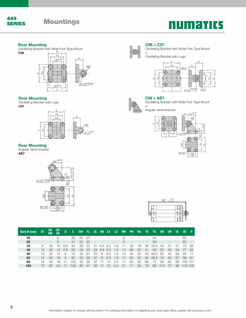
Rear MountingOscillating Bracket with LugsC07
Rear MountingOscillating Bracket with Wide Fork Type MountC08
C08 + C07Oscillating Bracket with Wide Fork Type Mount+Oscillating Bracket with Lugs
Rear MountingAngular clevis bracketAB7
C08 + AB7Oscillating Bracket with Wide Fork Type Mount+Angular clevis bracket
Bore Ø (mm) BT CBEM
CDCK D E EW FL GL HB L4 L5 MR PH RA TE TG UB UR UL XE Y
20 - - 8 - 38 16 20 - - - - 9 - - - 22 - - - 63 -25 - - 8 - 41 16 20 - - - - 9 - - - 26 - - - 65 -32 8 26 10 6.6 50 26 22 21 6.6 5.5 1.6 11 32 18 38 32.5 45 31 51 73 5640 10 28 12 6.6 58 28 25 24 6.6 5.5 1.6 13 36 22 41 38 52 35 54 77 6350 12 32 12 9 70 32 27 33 9 6.5 1.6 13 45 30 50 46.5 60 45 65 80 7163 12 40 16 9 85 40 32 37 9 6.5 1.6 17 50 35 52 56.5 70 50 67 89 8180 14 50 16 11 105 50 36 47 11 10 2.5 17 63 40 66 72 90 60 86 100 101
100 15 60 20 11 130 60 41 55 11 10 2.5 21 71 50 76 89 110 70 96 118 128
XE + 1
GLJs14
PH
Js1
5TE U
L
RAUR
4Ø HB
Ø CK H9e8
EM
L5B
T
UBh14
CBH14
Y
E=
=TG
==
===
=
==
TGE
FL
Ø CDH9/e8
MR
E
TG=
= =
=
= ==
===
TGE E=
=
Y
4Ø D
FL
FL
Ø CDH9/e8
TG
a
a
L4
FL
Ø CDH9
MR
E
TG=
= =
=
==
TG=
=E
EW= =
GLJs14
PH
Js1
5TE U
L
RAUR
4Ø HB
Ø CKH9e8
EM
L5B
T
FL
MR
E=
=TG
==
===
=
TGE

Information subject to change without notice. For ordering information or regarding your local sales office, please visit www.asco.com.9
Mountings 449 SERIES
Rear MountingOscillating Bracket with Narrow Fork Type MountC14
C14 + C13Oscillating Bracket with Narrow Fork Type Mount+ Spherical Eye Mount (Back Side)
Rear MountingSpherical Eye Mount (Back Side)C13
Rear MountingAngular clevis bracket spherical bearingAB5
Bore Ø (mm) BTCBEM
CDCK
D CG CPDLFM
EP G1 G2G3
Max.K1
K2 Max.
E EW FL GL HB L4 L5 MR PH
20 - - 8 - - - - - - - - - - 38 16 20 - - - - 9 -25 - - 8 - - - - - - - - - - 41 16 20 - - - - 9 -32 8 26 10 6.6 14 34 22 10.5 21 18 31 38 51 50 26 22 21 6.6 5.5 1.6 11 3240 10 28 12 6.6 16 40 25 12 24 22 35 41 54 58 28 25 24 6.6 5.5 1.6 13 3650 12 32 12 9 21 45 27 15 33 30 45 50 65 70 32 27 33 9 6.5 1.6 13 4563 12 40 16 9 21 51 32 15 37 35 50 52 67 85 40 32 37 9 6.5 1.6 17 5080 14 50 16 11 25 65 36 18 47 40 60 66 86 105 50 36 47 11 10 2.5 17 63100 15 60 20 11 25 75 41 18 55 50 70 76 96 130 60 41 55 11 10 2.5 21 71
XE + 1
CP
CG D10
E=
=TG
==
=
==
=TG
E
FM
Ø CF F7/h9
SR
DL
Ø CXH7
MS
E
TG
4°
4°
=
= =
=
==
TG=
=E
EX= =
+- 0,1
EP
G1Js14
Ø CFH7/h9
CH
Js15
K1
K2
G2G3
4Ø S5
EN
4° 4°
+0
- 0,
1
L65/
2
C14 + AB5Oscillating Bracket with Narrow Fork Type Mount+ Angular clevis bracket spherical bearing
E
TG
=
= =
=
= ==
===
==
TGE
4Ø DDLFM
Ø CFH7/h9
TG E
L65/1
G1Js14FM
10°
Ø CFH7/h9 CH
Js15
K1
K2
G2G3
4Ø S5
E=
=TG
==
===
=
TGE
EN
4° 4°
180°
+0
- 0,
1
L65/
2
Bore Ø (mm) RA TE TG UB UR UL XE Y
20 - - 22 - - - 63 -25 - - 26 - - - 65 -32 18 38 32.5 45 31 51 73 5640 22 41 38 52 35 54 77 6350 30 50 46.5 60 45 65 80 7163 35 52 56.5 70 50 67 89 8180 40 66 72 90 60 86 100 101100 50 76 89 110 70 96 118 128
Information subject to change without notice. For ordering information or regarding your local sales office, please visit www.asco.com.10
Mountings449 SERIES
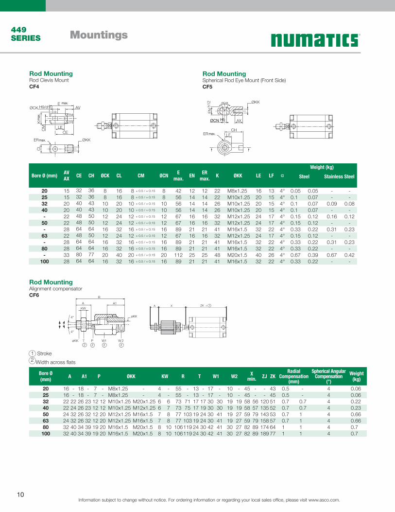
1 Stroke2 Width across flats
Rod MountingSpherical Rod Eye Mount (Front Side)CF5
Rod MountingRod Clevis MountCF4
ØCN H9
EN
h12
ER
ØKK
AX
CHLF
αα
Bore Ø (mm)AVAX
CE CH ØCK CL CM ØCNE
max.EN
ERmax.
K ØKK LE LF αWeight (kg)
Steel Stainless Steel
20 15 32 36 8 16 8 + 0.5 / + 0.15 8 42 12 12 22 M8x1.25 16 13 4° 0.05 0.05 - -25 15 32 36 8 16 8 + 0.5 / + 0.15 8 56 14 14 22 M10x1.25 20 15 4° 0.1 0.07 - -32 20 40 43 10 20 10 + 0.5 / + 0.15 10 56 14 14 26 M10x1.25 20 15 4° 0.1 0.07 0.09 0.0840 20 40 43 10 20 10 + 0.5 / + 0.15 10 56 14 14 26 M10x1.25 20 15 4° 0.1 0.07 - -- 22 48 50 12 24 12 + 0.5 / + 0.15 12 67 16 16 32 M12x1.25 24 17 4° 0.15 0.12 0.16 0.12
50 22 48 50 12 24 12 + 0.5 / + 0.15 12 67 16 16 32 M12x1.25 24 17 4° 0.15 0.12 - -- 28 64 64 16 32 16 + 0.5 / + 0.15 16 89 21 21 41 M16x1.5 32 22 4° 0.33 0.22 0.31 0.23
63 22 48 50 12 24 12 + 0.5 / + 0.15 12 67 16 16 32 M12x1.25 24 17 4° 0.15 0.12 - -- 28 64 64 16 32 16 + 0.5 / + 0.15 16 89 21 21 41 M16x1.5 32 22 4° 0.33 0.22 0.31 0.23
80 28 64 64 16 32 16 + 0.5 / + 0.15 16 89 21 21 41 M16x1.5 32 22 4° 0.33 0.22 - -- 33 80 77 20 40 20 + 0.5 / + 0.15 20 112 25 25 48 M20x1.5 40 26 4° 0.67 0.39 0.67 0.42
100 28 64 64 16 32 16 + 0.5 / + 0.15 16 89 21 21 41 M16x1.5 32 22 4° 0.33 0.22 - -
Rod MountingAlignment compensator CF6
A
KW
A1
R
4°
4°
øKK
W2W1PTøKK2 2 2 2
Bore Ø (mm)
A A1 P ØKK KW R T W1 W2 Xmin. ZJ ZK
Radial Compensation
(mm)
Spherical Angular Compensation
(°)
Weight (kg)
20 16 - 18 - 7 - M8x1.25 - 4 - 55 - 13 - 17 - 10 - 45 - - 43 0.5 - 4 0.0625 16 - 18 - 7 - M8x1.25 - 4 - 55 - 13 - 17 - 10 - 45 - - 45 0.5 - 4 0.0632 22 22 26 23 12 12 M10x1.25 M20x1.25 6 6 73 71 17 17 30 30 19 19 58 56 120 51 0.7 0.7 4 0.2240 22 24 26 23 12 12 M10x1.25 M12x1.25 6 7 73 75 17 19 30 30 19 19 58 57 135 52 0.7 0.7 4 0.2350 24 32 26 32 12 20 M12x1.25 M16x1.5 7 8 77 103 19 24 30 41 19 27 59 79 143 53 0.7 1 4 0.6663 24 32 26 32 12 20 M12x1.25 M16x1.5 7 8 77 103 19 24 30 41 19 27 59 79 158 57 0.7 1 4 0.6680 32 40 34 39 19 20 M16x1.5 M20x1.5 8 10 106119 24 30 42 41 30 27 82 89 174 64 1 1 4 0.7100 32 40 34 39 19 20 M16x1.5 M20x1.5 8 10 106119 24 30 42 41 30 27 82 89 189 77 1 1 4 0.7
ZK + 1A X
max.
ØCK H9/d10
ER ØKK
E
K C
M
AV
LECE
CL
max.
max.
max
.
Information subject to change without notice. For ordering information or regarding your local sales office, please visit www.asco.com.11
Mountings 449 SERIES
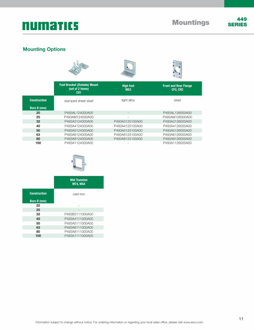
Foot Bracket (Outside) Mount(set of 2 items)
C01
High footMS3
Front and Rear FlangeCF2, CR2
Construction stamped sheet steel light alloy steel
Bore Ø (mm)20 P493AL124000A00 - P493AL126000A0025 P493AM124000A00 - P493AM126000A0032 P493A3124000A00 P493A3125100A00 P493A3126000A0040 P493A4124000A00 P493A4125100A00 P493A4126000A00 50 P493A5124000A00 P493A5125100A00 P493A5126000A0063 P493A6124000A00 P493A6125100A00 P493A6126000A00 80 P493A8124000A00 P493A8125100A00 P493A8126000A00 100 P493A1124000A00 - P493A1126000A00
Mid TrunnionMT4, MS4
Construction cast iron
Bore Ø (mm)20 -25 -32 P493B3111000A0040 P493A4111000A0050 P493A5111000A0063 P493A6111000A0080 P493A8111000A00100 P493A1111000A00
Mounting Options
Information subject to change without notice. For ordering information or regarding your local sales office, please visit www.asco.com.12
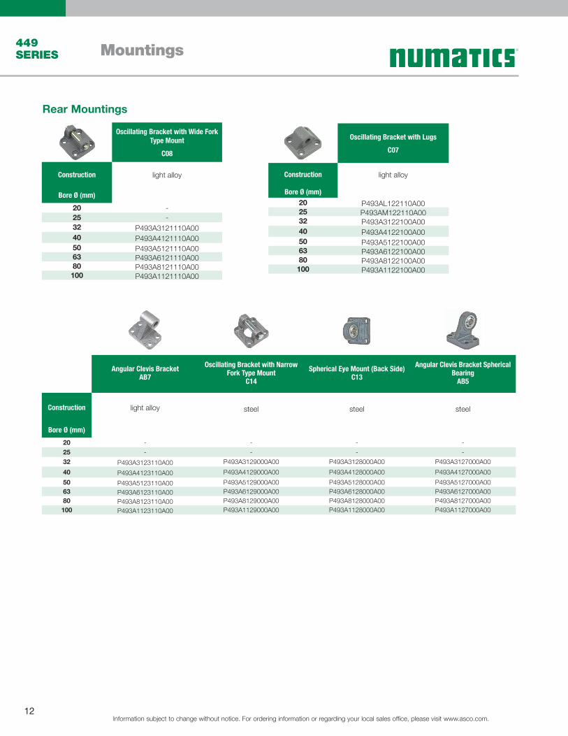
Mountings449 SERIES
Oscillating Bracket with Wide Fork Type Mount
C08
Construction light alloy
Bore Ø (mm)
20 -25 -32 P493A3121110A0040 P493A4121110A0050 P493A5121110A0063 P493A6121110A00 80 P493A8121110A00 100 P493A1121110A00
Oscillating Bracket with Lugs
C07
Construction light alloy
Bore Ø (mm)20 P493AL122110A0025 P493AM122110A0032 P493A3122100A0040 P493A4122100A0050 P493A5122100A00 63 P493A6122100A0080 P493A8122100A00 100 P493A1122100A00
Angular Clevis BracketAB7
Oscillating Bracket with Narrow Fork Type Mount
C14
Spherical Eye Mount (Back Side)C13
Angular Clevis Bracket Spherical Bearing
AB5
Construction light alloy steel steel steel
Bore Ø (mm)
20 - - - -25 - - - -32 P493A3123110A00 P493A3129000A00 P493A3128000A00 P493A3127000A00 40 P493A4123110A00 P493A4129000A00 P493A4128000A00 P493A4127000A0050 P493A5123110A00 P493A5129000A00 P493A5128000A00 P493A5127000A0063 P493A6123110A00 P493A6129000A00 P493A6128000A00 P493A6127000A0080 P493A8123110A00 P493A8129000A00 P493A8128000A00 P493A8127000A00100 P493A1123110A00 P493A1129000A00 P493A1128000A00 P493A1127000A00
Rear Mountings
Information subject to change without notice. For ordering information or regarding your local sales office, please visit www.asco.com.13
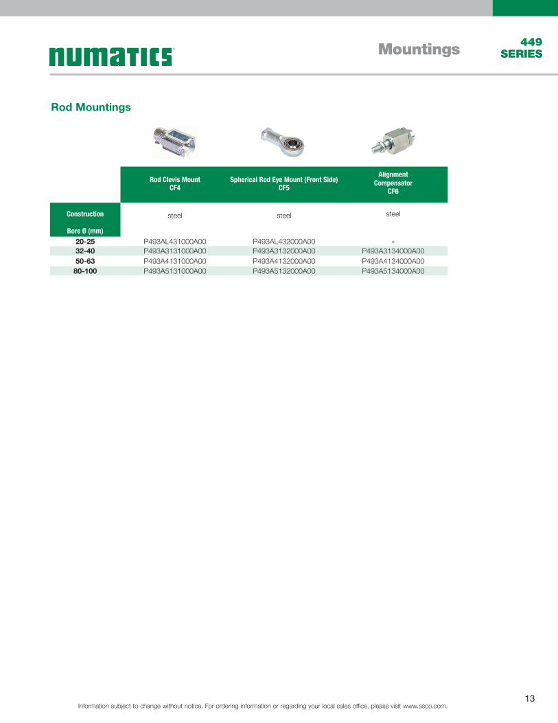
Mountings 449 SERIES
Rod Clevis MountCF4
Spherical Rod Eye Mount (Front Side)CF5
Alignment Compensator
CF6
Construction steel steel steel
Bore Ø (mm)20-25 P493AL431000A00 P493AL432000A00 -32-40 P493A3131000A00 P493A3132000A00 P493A3134000A0050-63 P493A4131000A00 P493A4132000A00 P493A4134000A00
80-100 P493A5131000A00 P493A5132000A00 P493A5134000A00
Rod Mountings
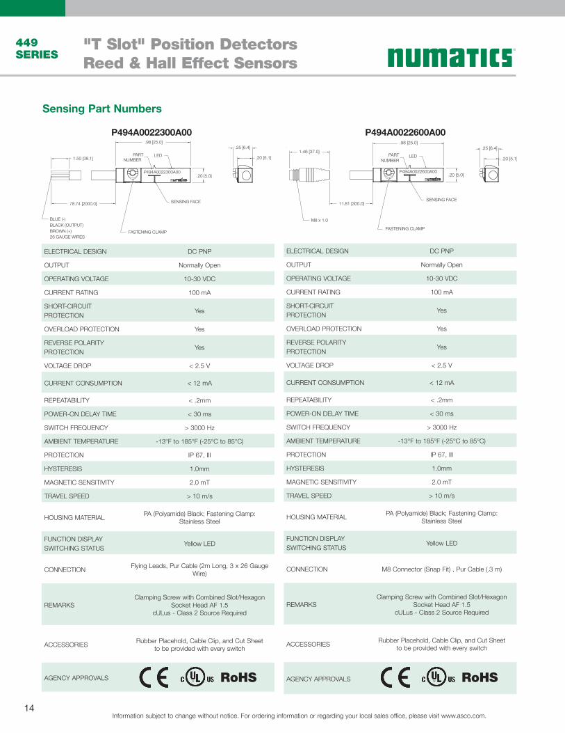
"T Slot" Position Detectors Reed & Hall Effect Sensors
Information subject to change without notice. For ordering information or regarding your local sales office, please visit www.asco.com.14
449 SERIES
ELECTRICAL DESIGN DC PNP
OUTPUT Normally Open
OPERATING VOLTAGE 10-30 VDC
CURRENT RATING 100 mA
SHORT-CIRCUIT PROTECTION
Yes
OVERLOAD PROTECTION Yes
REVERSE POLARITY PROTECTION
Yes
VOLTAGE DROP < 2.5 V
CURRENT CONSUMPTION < 12 mA
REPEATABILITY < .2mm
POWER-ON DELAY TIME < 30 ms
SWITCH FREQUENCY > 3000 Hz
AMBIENT TEMPERATURE -13°F to 185°F (-25°C to 85°C)
PROTECTION IP 67, III
HYSTERESIS 1.0mm
MAGNETIC SENSITIVITY 2.0 mT
TRAVEL SPEED > 10 m/s
HOUSING MATERIAL PA (Polyamide) Black; Fastening Clamp:Stainless Steel
FUNCTION DISPLAY SWITCHING STATUS
Yellow LED
CONNECTION Flying Leads, Pur Cable (2m Long, 3 x 26 Gauge Wire)
REMARKSClamping Screw with Combined Slot/Hexagon
Socket Head AF 1.5cULus - Class 2 Source Required
ACCESSORIES Rubber Placehold, Cable Clip, and Cut Sheetto be provided with every switch
AGENCY APPROVALS
ELECTRICAL DESIGN DC PNP
OUTPUT Normally Open
OPERATING VOLTAGE 10-30 VDC
CURRENT RATING 100 mA
SHORT-CIRCUIT PROTECTION
Yes
OVERLOAD PROTECTION Yes
REVERSE POLARITY PROTECTION
Yes
VOLTAGE DROP < 2.5 V
CURRENT CONSUMPTION < 12 mA
REPEATABILITY < .2mm
POWER-ON DELAY TIME < 30 ms
SWITCH FREQUENCY > 3000 Hz
AMBIENT TEMPERATURE -13°F to 185°F (-25°C to 85°C)
PROTECTION IP 67, III
HYSTERESIS 1.0mm
MAGNETIC SENSITIVITY 2.0 mT
TRAVEL SPEED > 10 m/s
HOUSING MATERIAL PA (Polyamide) Black; Fastening Clamp:Stainless Steel
FUNCTION DISPLAY SWITCHING STATUS
Yellow LED
CONNECTION M8 Connector (Snap Fit) , Pur Cable (.3 m)
REMARKSClamping Screw with Combined Slot/Hexagon
Socket Head AF 1.5cULus - Class 2 Source Required
ACCESSORIES Rubber Placehold, Cable Clip, and Cut Sheetto be provided with every switch
AGENCY APPROVALS
.98 [25.0]
.20 [5.0]
SENSING FACE
LED
P494A0022600A00
.25 [6.4]
.20 [5.1]
11.81 [300.0]
1.46 [37.0]
M8 x 1.0
PARTNUMBER
FASTENING CLAMP
.98 [25.0]
.20 [5.0]
FASTENING CLAMP
SENSING FACE
LED
P494A0022300A00
.25 [6.4]
.20 [5.1]PARTNUMBER
78.74 [2000.0]
1.50 [38.1]
BLUE (-)BLACK (OUTPUT) BROWN (+) 26 GAUGE WIRES
P494A0022300A00 P494A0022600A00
RoHS
Sensing Part Numbers
RoHS
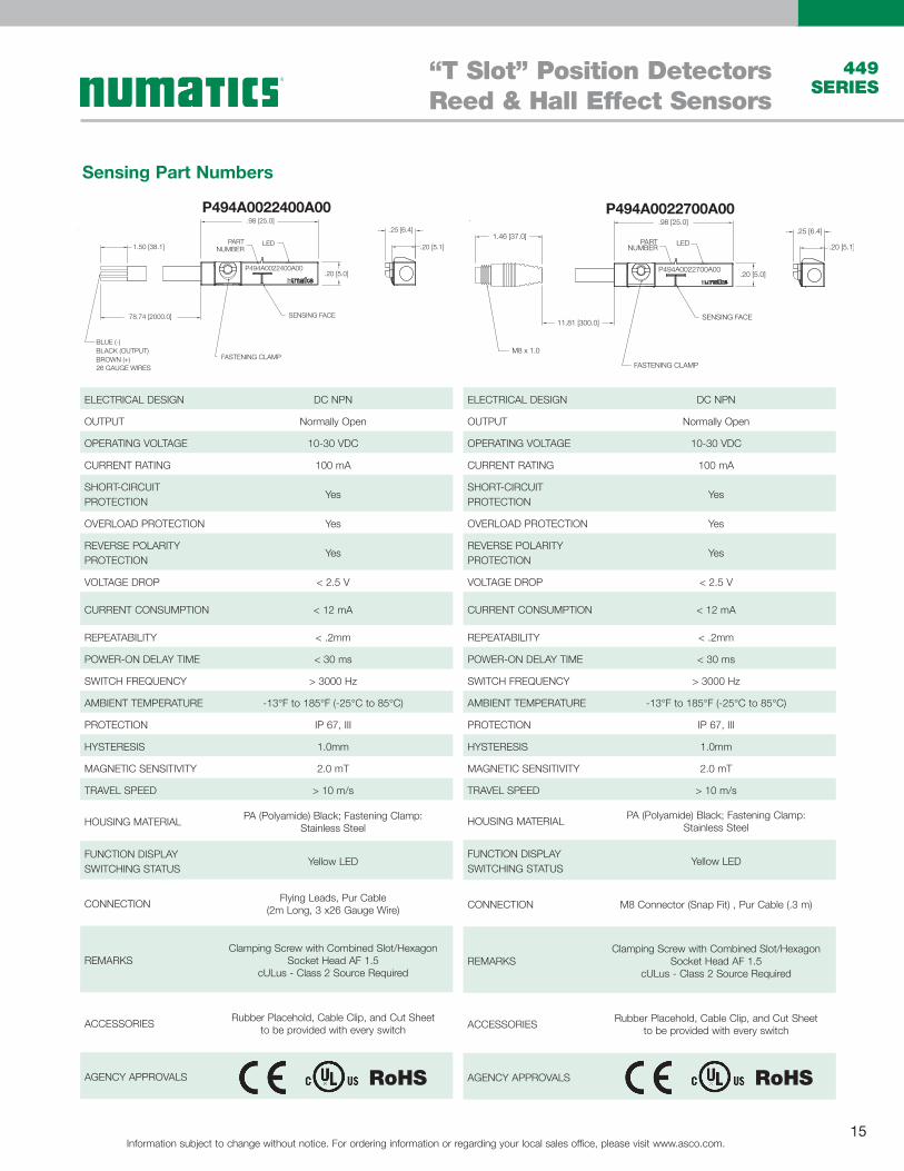
“T Slot” Position Detectors Reed & Hall Effect Sensors
Information subject to change without notice. For ordering information or regarding your local sales office, please visit www.asco.com.15
449 SERIES
ELECTRICAL DESIGN DC NPN
OUTPUT Normally Open
OPERATING VOLTAGE 10-30 VDC
CURRENT RATING 100 mA
SHORT-CIRCUIT PROTECTION
Yes
OVERLOAD PROTECTION Yes
REVERSE POLARITY PROTECTION
Yes
VOLTAGE DROP < 2.5 V
CURRENT CONSUMPTION < 12 mA
REPEATABILITY < .2mm
POWER-ON DELAY TIME < 30 ms
SWITCH FREQUENCY > 3000 Hz
AMBIENT TEMPERATURE -13°F to 185°F (-25°C to 85°C)
PROTECTION IP 67, III
HYSTERESIS 1.0mm
MAGNETIC SENSITIVITY 2.0 mT
TRAVEL SPEED > 10 m/s
HOUSING MATERIAL PA (Polyamide) Black; Fastening Clamp:Stainless Steel
FUNCTION DISPLAY SWITCHING STATUS
Yellow LED
CONNECTION M8 Connector (Snap Fit) , Pur Cable (.3 m)
REMARKSClamping Screw with Combined Slot/Hexagon
Socket Head AF 1.5cULus - Class 2 Source Required
ACCESSORIES Rubber Placehold, Cable Clip, and Cut Sheetto be provided with every switch
AGENCY APPROVALS
.98 [25.0]
.20 [5.0]
SENSING FACE
LED
P494A0022700A00
.25 [6.4]
.20 [5.1]
11.81 [300.0]
1.46 [37.0]
M8 x 1.0
PARTNUMBER
FASTENING CLAMP
ELECTRICAL DESIGN DC NPN
OUTPUT Normally Open
OPERATING VOLTAGE 10-30 VDC
CURRENT RATING 100 mA
SHORT-CIRCUIT PROTECTION
Yes
OVERLOAD PROTECTION Yes
REVERSE POLARITY PROTECTION
Yes
VOLTAGE DROP < 2.5 V
CURRENT CONSUMPTION < 12 mA
REPEATABILITY < .2mm
POWER-ON DELAY TIME < 30 ms
SWITCH FREQUENCY > 3000 Hz
AMBIENT TEMPERATURE -13°F to 185°F (-25°C to 85°C)
PROTECTION IP 67, III
HYSTERESIS 1.0mm
MAGNETIC SENSITIVITY 2.0 mT
TRAVEL SPEED > 10 m/s
HOUSING MATERIAL PA (Polyamide) Black; Fastening Clamp:Stainless Steel
FUNCTION DISPLAY SWITCHING STATUS
Yellow LED
CONNECTION Flying Leads, Pur Cable (2m Long, 3 x26 Gauge Wire)
REMARKSClamping Screw with Combined Slot/Hexagon
Socket Head AF 1.5cULus - Class 2 Source Required
ACCESSORIES Rubber Placehold, Cable Clip, and Cut Sheetto be provided with every switch
AGENCY APPROVALS
.98 [25.0]
.20 [5.0]
SENSING FACE
LED
P494A0022400A00
.25 [6.4]
.20 [5.1]PART
NUMBER
78.74 [2000.0]
1.50 [38.1]
BLUE (-)BLACK (OUTPUT) BROWN (+) 26 GAUGE WIRES
FASTENING CLAMP
P494A0022400A00 P494A0022700A00
Sensing Part Numbers
RoHS RoHS
"T Slot" Position Detectors Reed & Hall Effect Sensors
Information subject to change without notice. For ordering information or regarding your local sales office, please visit www.asco.com.16
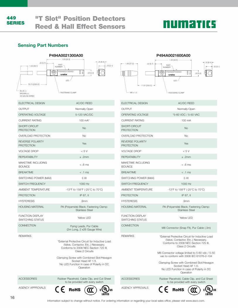
449 SERIES
ELECTRICAL DESIGN AC/DC REED
OUTPUT Normally Open
OPERATING VOLTAGE 5-120 VAC/DC
CURRENT RATING 100 mA*
SHORT-CIRCUIT PROTECTION
No
OVERLOAD PROTECTION No
REVERSE POLARITY PROTECTION
Yes
VOLTAGE DROP < 5 V
REPEATABILITY ± .2mm
MAKETIME INCLUDING BOUNCE
< .6 ms
BREAKTIME < .1 ms
SWITCHING POWER (MAX) 5 W
SWITCH FREQUENCY 1000 Hz
AMBIENT TEMPERATURE -13°F to 158°F (-25°C to 70°C)
PROTECTION IP 67, II
HYSTERESIS .9mm
HOUSING MATERIAL PA (Polyamide) Black; Fastening Clamp:Stainless Steel
FUNCTION DISPLAY SWITCHING STATUS
Yellow LED
CONNECTION Flying Leads, Pur Cable (2m Long, 2 x26 Gauge Wire)
REMARKS
*External Protective Circuit for Inductive Load (Valve, Contactor, Etc..) Necessary.
Conforms to 2008 NEC Section 725 III, Class 2 Circuits
Clamping Screw with Combined Slot/Hexagon Socket Head AF 1.5.
No LED Function in case of Polarity in DC Operation
ACCESSORIES Rubber Placehold, Cable Clip, and Cut Sheetto be provided with every switch
AGENCY APPROVALS
ELECTRICAL DESIGN AC/DC REED
OUTPUT Normally Open
OPERATING VOLTAGE *5-60 VDC / 5-50 VAC
CURRENT RATING 100 mA
SHORT-CIRCUIT PROTECTION
No
OVERLOAD PROTECTION No
REVERSE POLARITY PROTECTION
Yes
VOLTAGE DROP < 5 V
REPEATABILITY ± .2mm
MAKETIME INCLUDING BOUNCE
< .6 ms
BREAKTIME < .1 ms
SWITCHING POWER (MAX) 5 W
SWITCH FREQUENCY 1000 Hz
AMBIENT TEMPERATURE -13°F to 158°F (-25°C to 70°C)
PROTECTION IP 67, II
HYSTERESIS .9mm
HOUSING MATERIAL PA (Polyamide) Black; Fastening Clamp:Stainless Steel
FUNCTION DISPLAY SWITCHING STATUS
Yellow LED
CONNECTIONM8 Connector (Snap Fit), Pur Cable (.3m)
REMARKS *External Protective Circuit for Inductive Load (Valve, Contactor, Etc..) Necessary.
Conforms to 2008 NEC Section 725 III, Class 2 Circuits
M8 Connector voltage limited to 5-60 vdc / 5-50 vac to conform with 2008 IEC 61076-2-104
Clamping Screw with Combined Slot/Hexagon Socket Head AF 1.5.
No LED Function in case of Polarity in DC Operation
ACCESSORIES Rubber Placehold, Cable Clip, and Cut Sheetto be provided with every switch
AGENCY APPROVALS
.25 [6.4]
.20 [5.1]
11.81 [300.0]
1.46 [37.0]
M8 x 1.0
1.20 [30.5]
.20 [5.0]
LED
P494A0021600A00
T AA0809
PARTNUMBER
.22 [5.7]
FASTENING CLAMP
.25 [6.4]
.20 [5.1]
1.20 [30.5]
.20 [5.0]
LED
P494A0021300A00
T AA0809
PARTNUMBER
.22 [5.7]
FASTENING CLAMP
78.74 [2000.0]
1.50 [38.1]
BLUE (-)BROWN (+) 26 GAUGE WIRES
P494A0021300A00 P494A0021600A00
Sensing Part Numbers
RoHS RoHS
Notes
Information subject to change without notice. For ordering information or regarding your local sales office, please visit www.asco.com.17
449 SERIES

Notes
Information subject to change without notice. For ordering information or regarding your local sales office, please visit www.asco.com.18
449 SERIES

World Class Supplier of Pneumatic Components
LT-449 Series Rev 01/16 © Numatics Inc. 2012 - 2016
Numatics® is registered in the United States and elsewhere
World HeadquartersUSA Numatics, Incorporated46280 Dylan DriveNovi, Michigan 48377
P: 248-596-3200 F: 248-596-3201
Canada Numatics, LtdP: 519-758-2700 F: 519-758-5540
Brazil Ascoval Ind.e Comercio LtdaP: (55) 11-4208-1700 F: (55) 11-4195-3970
México - Ascomatica SA de CVP: 52 55 58 09 56 40 (DF y Area metropolitana)P: 01 800 000 2726 (Interior de la República) F: 52 55 58 09 56 60
Numatics, Inc. | Tel (248) 596-3200 | www.asco.com | email: [email protected]