
430429-249 Heavy Duty CCCV
58
Heavy Duty CC/CV Semiautomatic Solid-State Control Wire Feeder Model 2460 For the Following Specs: • 6877A-1 4-Roll Drive, 40-600 IPM • 6877B-1 4-Roll Drive, 40-600 IPM • 6877A-2 4-Roll Drive, 20-300 IPM • 6877B-2 4-Roll Drive, 20-300 IPM OWNER’S MANUAL Number 430429-249 (Rev - AC) Revised April 14, 2005 THERMAL ARC INC., W. LEBANON, NH 03784, USA IMPORTANT: Read these instructions before installing, operating, or servicing this system.
-
Upload
samuel-manduca -
Category
Documents
-
view
216 -
download
0
Transcript of 430429-249 Heavy Duty CCCV

Heavy Duty CC/CVSemiautomatic Solid-State ControlWire Feeder Model 2460
For the Following Specs:• 6877A-1 4-Roll Drive, 40-600 IPM• 6877B-1 4-Roll Drive, 40-600 IPM• 6877A-2 4-Roll Drive, 20-300 IPM• 6877B-2 4-Roll Drive, 20-300 IPM
OWNER’S MANUAL Number 430429-249 (Rev - AC)Revised April 14, 2005
THERMAL ARC INC., W. LEBANON, NH 03784, USA
IMPORTANT: Read these instructions before installing, operating, or servicing this system.

INTRODUCTION 1How To Use This Manual . . . . . . . . . . . . . . . . . . . . . . . . . . . . . . . . . . 1-1Equipment Identification . . . . . . . . . . . . . . . . . . . . . . . . . . . . . . . . . . 1-1Receipt Of Equipment . . . . . . . . . . . . . . . . . . . . . . . . . . . . . . . . . . . 1-1
SAFETY INSTRUCTIONS AND WARNINGS 2
DESCRIPTION OF EQUIPMENT 3General Description . . . . . . . . . . . . . . . . . . . . . . . . . . . . . . . . . . . . . 3-1Current Capacity and Rating . . . . . . . . . . . . . . . . . . . . . . . . . . . . . . . . 3-1Feedhead Assembly . . . . . . . . . . . . . . . . . . . . . . . . . . . . . . . . . . . . 3-2Tabulated Data . . . . . . . . . . . . . . . . . . . . . . . . . . . . . . . . . . . . . . . 3-2Control Box Assembly . . . . . . . . . . . . . . . . . . . . . . . . . . . . . . . . . . . 3-2Wire Reel Support Assembly . . . . . . . . . . . . . . . . . . . . . . . . . . . . . . . . 3-2Baseplate . . . . . . . . . . . . . . . . . . . . . . . . . . . . . . . . . . . . . . . . . . 3-2Options . . . . . . . . . . . . . . . . . . . . . . . . . . . . . . . . . . . . . . . . . . . 3-2
OPERATION 4Prewelding Checks . . . . . . . . . . . . . . . . . . . . . . . . . . . . . . . . . . . . . 4-1Welding . . . . . . . . . . . . . . . . . . . . . . . . . . . . . . . . . . . . . . . . . . . 4-1
PARTS LIST 5Equipment Identification . . . . . . . . . . . . . . . . . . . . . . . . . . . . . . . . . . 5-1How To Use This Parts List . . . . . . . . . . . . . . . . . . . . . . . . . . . . . . . . . 5-1How To Select Recommended Spares . . . . . . . . . . . . . . . . . . . . . . . . . . . 5-1
CONTROL BOX ASSEMBLY NO. 376783A & 376783B TIP-218
FEEDHEAD ASSEMBLY NO. 376799A-1, -2, -3, -4 TIP-219
PARTS LIST FOR ASSEMBLY NO. 376799A-1, -2, -3, -4 MPL-224
BASE ASSEMBLY PART NO. 375769-1 & -4 TIP-127
WIRE SPOOL SUPPORT I-169
DIAGRAMS
430429-249Table of Contents
December 1, 1997 Revised
April14, 2005 Revised 1-1
430429-249
INTRODUCTION
INTRODUCTION
How To Use This Manual
This Owner’s Manual usually applies to just the under-lined specification or part numbers listed on the cover. Ifnone are underlined, they are all covered by this manual.
To ensure safe operation, read the entire manual, includ-ing the chapter on safety instructions and warnings.
Throughout this manual, the words WARNING,CAUTION, and NOTE may appear. Pay particular atten-tion to the information provided under these headings.These special headings are easily recognized as follows:
WARNING
A WARNING gives information regardingpossible personal injury.
CAUTION
A CAUTION refers to possible equipment damage.
NOTE
A NOTE offers helpful information concerning cer-tain operating procedures.
Additional copies of this manual may be purchased bycontacting Thermal Arc at the address and phone numbergiven in the next section. Include the Owner’s Manualnumber and equipment identification numbers.
Electronic copies of this manual can also be downloadedat no charge in Acrobat PDF format by going to the Ther-mal Arc web site listed below and clicking on the Litera-ture Library link:
http://www.thermadyne.com/tai
Equipment Identification
The unit’s identification number (specification or partnumber), model, and serial number usually appear on anameplate attached to the control panel. In some cases,the nameplate may be attached to the rear panel. Equip-ment which does not have a control panel such as gunand cable assemblies is identified only by the specifica-tion or part number printed on the shipping container.Record these numbers for future reference.
Receipt Of Equipment
When you receive the equipment, check it against the in-voice to make sure it is complete and inspect the equip-ment for possible damage due to shipping. If there is anydamage, notify the carrier immediately to file a claim. Fur-nish complete information concerning damage claims orshipping errors to:
Thermadyne, Inc.Thermal Arc Order Department82 Benning StreetWest Lebanon, New Hampshire, USA 03784
For more information, call (603) 298-5711.
Include all equipment identification numbers as describedabove along with a full description of the parts in error.
Move the equipment to the installation site before uncratingthe unit. Use care to avoid damaging the equipment whenusing bars, hammers, etc., to uncrate the unit.
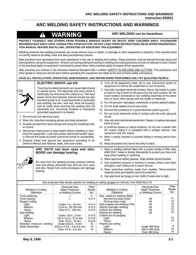
PROTECT YOURSELF AND OTHERS FROM POSSIBLE SERIOUS INJURY OR DEATH. KEEP CHILDREN AWAY. PACEMAKERWEARERS KEEP AWAY UNTIL CONSULTING YOUR DOCTOR. DO NOT LOSE THESE INSTRUCTIONS. READ OPERATING/INSTRUC-TION MANUAL BEFORE INSTALLING, OPERATING OR SERVICING THIS EQUIPMENT.
Welding products and welding processes can cause serious injury or death, or damage to other equipment or property, if the operator doesnot strictly observe all safety rules and take precautionary actions.
Safe practices have developed from past experience in the use of welding and cutting. These practices must be learned through study andtraining before using this equipment. Anyone not having extensive training in welding and cutting practices should not attempt to weld. Certainof the practices apply to equipment connected to power lines; other practices apply to engine driven equipment.
Safe practices are outlined in the American National Standard Z49.1 entitled: SAFETY IN WELDING AND CUTTING. This publication andother guides to what you should learn before operating this equipment are listed at the end of these safety precautions.
HAVE ALL INSTALLATION, OPERATION, MAINTENANCE, AND REPAIR WORK PERFORMED ONLY BY QUALIFIED PEOPLE.
ELECTRIC SHOCK can kill.
Touching live electrical parts can cause fatal shocksor severe burns. The electrode and work circuit iselectrically live whenever the output is on. The inputpower circuit and machine internal circuits are alsolive when power is on. In semiautomatic or automaticwire welding, the wire, wire reel, drive roll housing,and all metal parts touching the welding wire areelectrically live. Incorrectly installed or improperlygrounded equipment is a hazard.
1. Do not touch live electrical parts.2. Wear dry, hole-free insulating gloves and body protection.3. Insulate yourself from work and ground using dry insulating mats
or covers.4. Disconnect input power or stop engine before installing or serv-
icing this equipment. Lock input power disconnect switch open,or remove line fuses so power cannot be turned on accidentally.
5. Properly install and ground this equipment according to itsOwner’s Manual and national, state, and local codes.
6. Turn off all equipment when not in use. Disconnect power toequipment if it will be left unattended or out of service.
7. Use fully insulated electrode holders. Never dip holder in waterto cool it or lay it down on the ground or the work surface. Do nottouch holders connected to two welding machines at the sametime or touch other people with the holder or electrode.
8. Do not use worn, damaged, undersized, or poorly spliced cables.9. Do not wrap cables around your body.
10. Ground the workpiece to a good electrical (earth) ground.11. Do not touch electrode while in contact with the work (ground)
circuit.12. Use only well-maintained equipment. Repair or replace damaged
parts at once.13. In confined spaces or damp locations, do not use a welder with
AC output unless it is equipped with a voltage reducer. Useequipment with DC output.
14. Wear a safety harness to prevent falling if working above floorlevel.
15. Keep all panels and covers securely in place.
ARC WELDING SAFETY INSTRUCTIONS AND WARNINGS
ARC RAYS can burn eyes and skin;NOISE can damage hearing.
Arc rays from the welding process produce intenseheat and strong ultraviolet rays that can burn eyesand skin. Noise from some processes can damagehearing.
1. Wear a welding helmet fitted with a proper shade of filter (seeANSI Z49.1 listed in Safety Standards) to protect your face andeyes when welding or watching.
2. Wear approved safety glasses. Side shields recommended.3. Use protective screens or barriers to protect others from flash
and glare; warn others not to watch the arc.4. Wear protective clothing made from durable, flame-resistant
material (wool and leather) and foot protection.5. Use approved ear plugs or ear muffs if noise level is high.
ARC WELDING can be hazardous.
Eye protection filter shade selector for welding or cutting (goggles or helmet), from AWS A6.2-73.
Welding or CuttingOperation
Torch solderingTorch brazingOxygen cutting
LightMediumHeavy
Gas weldingLightMediumHeavy
Shielded metal-arc welding(stick) electrodes
Welding or CuttingOperation
Gas metal-arc welding (MIG)Non-ferrous base metalFerrous base metal
Gas tungsten arc welding (TIG)Atomic hydrogen weldingCarbon arc weldingPlasma arc weldingCarbon arc air gouging
LightHeavy
Plasma arc cuttingLightMediumHeavy
Electrode SizeMetal Thickness
or Welding Current——
Under 1 in., 25 mm1 to 6 in., 25-150 mmOver 6 in., 150 mm
Under 1/8 in., 3 mm1/8 to 1/2 in., 3-12 mm
Over 1/2 in., 12 mmUnder 5/32 in., 4 mm
5/32 to 1/4 in., 4 to 6.4 mmOver 1/4 in., 6.4 mm
Electrode SizeMetal Thickness
or Welding Current
AllAllAllAllAllAll
Under 300 Amp300 to 400 AmpOver 400 Amp
FilterShade
No.2
3 or 4
3 or 44 or 55 or 6
4 or 55 or 66 or 8
101214
FilterShade
No.
111212121212
1214
91214
ARC WELDING SAFETY INSTRUCTIONS AND WARNINGSInstruction 830001
May 8, 1996 2-1
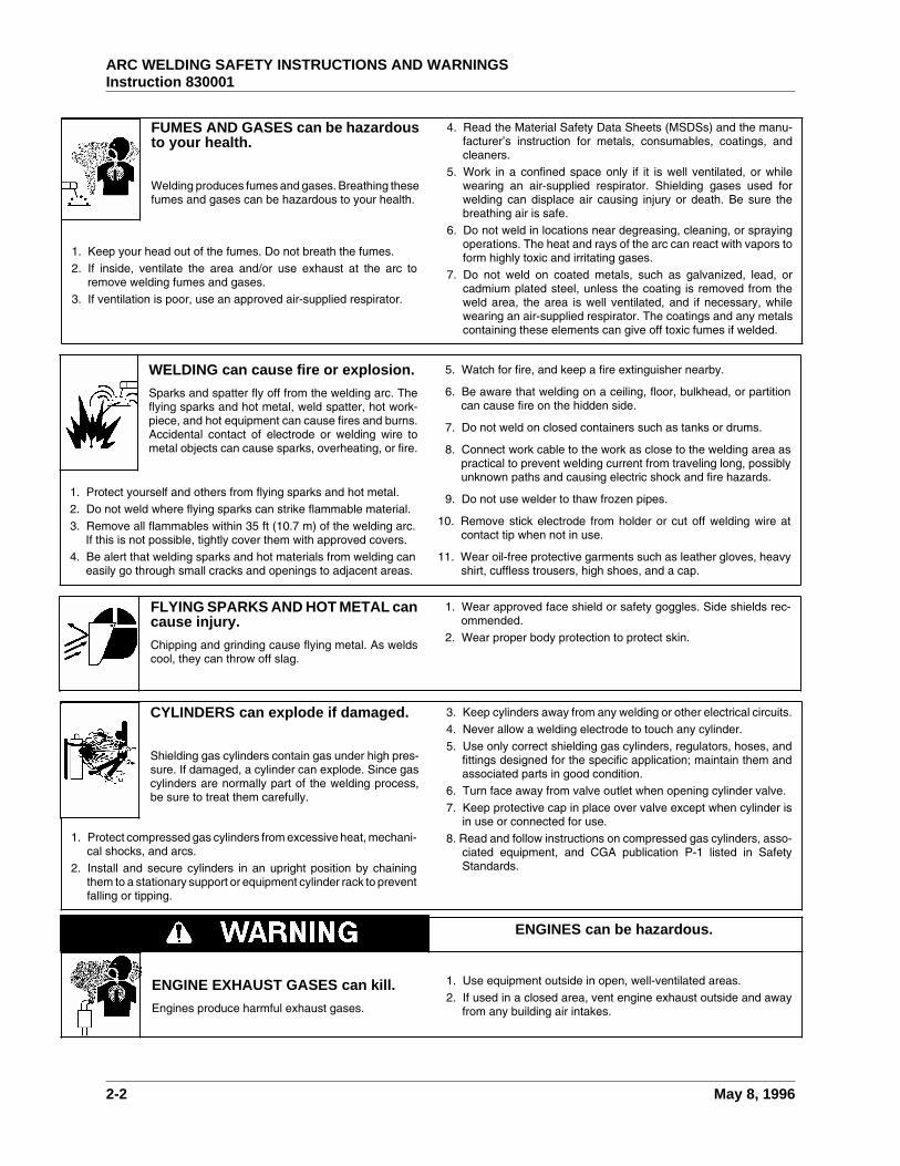
WELDING can cause fire or explosion.
Sparks and spatter fly off from the welding arc. Theflying sparks and hot metal, weld spatter, hot work-piece, and hot equipment can cause fires and burns.Accidental contact of electrode or welding wire tometal objects can cause sparks, overheating, or fire.
1. Protect yourself and others from flying sparks and hot metal.2. Do not weld where flying sparks can strike flammable material.3. Remove all flammables within 35 ft (10.7 m) of the welding arc.
If this is not possible, tightly cover them with approved covers.4. Be alert that welding sparks and hot materials from welding can
easily go through small cracks and openings to adjacent areas.
5. Watch for fire, and keep a fire extinguisher nearby.
6. Be aware that welding on a ceiling, floor, bulkhead, or partitioncan cause fire on the hidden side.
7. Do not weld on closed containers such as tanks or drums.
8. Connect work cable to the work as close to the welding area aspractical to prevent welding current from traveling long, possiblyunknown paths and causing electric shock and fire hazards.
9. Do not use welder to thaw frozen pipes.
10. Remove stick electrode from holder or cut off welding wire atcontact tip when not in use.
11. Wear oil-free protective garments such as leather gloves, heavyshirt, cuffless trousers, high shoes, and a cap.
FLYING SPARKS AND HOT METAL cancause injury.
Chipping and grinding cause flying metal. As weldscool, they can throw off slag.
1. Wear approved face shield or safety goggles. Side shields rec-ommended.
2. Wear proper body protection to protect skin.
CYLINDERS can explode if damaged.
Shielding gas cylinders contain gas under high pres-sure. If damaged, a cylinder can explode. Since gascylinders are normally part of the welding process,be sure to treat them carefully.
1. Protect compressed gas cylinders from excessive heat, mechani-cal shocks, and arcs.
2. Install and secure cylinders in an upright position by chainingthem to a stationary support or equipment cylinder rack to preventfalling or tipping.
3. Keep cylinders away from any welding or other electrical circuits.4. Never allow a welding electrode to touch any cylinder.5. Use only correct shielding gas cylinders, regulators, hoses, and
fittings designed for the specific application; maintain them andassociated parts in good condition.
6. Turn face away from valve outlet when opening cylinder valve.7. Keep protective cap in place over valve except when cylinder is
in use or connected for use.8. Read and follow instructions on compressed gas cylinders, asso-
ciated equipment, and CGA publication P-1 listed in SafetyStandards.
ENGINES can be hazardous.
ENGINE EXHAUST GASES can kill.
Engines produce harmful exhaust gases.
1. Use equipment outside in open, well-ventilated areas.2. If used in a closed area, vent engine exhaust outside and away
from any building air intakes.
FUMES AND GASES can be hazardousto your health.
Welding produces fumes and gases. Breathing thesefumes and gases can be hazardous to your health.
1. Keep your head out of the fumes. Do not breath the fumes.2. If inside, ventilate the area and/or use exhaust at the arc to
remove welding fumes and gases.3. If ventilation is poor, use an approved air-supplied respirator.
4. Read the Material Safety Data Sheets (MSDSs) and the manu-facturer’s instruction for metals, consumables, coatings, andcleaners.
5. Work in a confined space only if it is well ventilated, or whilewearing an air-supplied respirator. Shielding gases used forwelding can displace air causing injury or death. Be sure thebreathing air is safe.
6. Do not weld in locations near degreasing, cleaning, or sprayingoperations. The heat and rays of the arc can react with vapors toform highly toxic and irritating gases.
7. Do not weld on coated metals, such as galvanized, lead, orcadmium plated steel, unless the coating is removed from theweld area, the area is well ventilated, and if necessary, whilewearing an air-supplied respirator. The coatings and any metalscontaining these elements can give off toxic fumes if welded.
ARC WELDING SAFETY INSTRUCTIONS AND WARNINGSInstruction 830001
2-2 May 8, 1996

STEAM AND PRESSURIZED HOTCOOLANT can burn face, eyes, andskin.
The coolant in the radiator can be very hot and underpressure.
1. Do not remove radiator cap when engine is hot. Allow engine tocool.
2. Wear gloves and put a rag over cap area when removing cap.3. Allow pressure to escape before completely removing cap.
PRINCIPAL SAFETY STANDARDS
Safety in Welding and Cutting, ANSI Standard Z49.1, from AmericanWelding Society, 550 N.W. LeJeune Rd., Miami, FL 33126.
Safety and Health Standards, OSHA 29 CFR 1910, from Superinten-dent of Documents, U.S. Government Printing Office, Washington,D.C. 20402.
Recommended Safe Practices for the Preparation for Welding andCutting of Containers That Have Held Hazardous Substances, Ameri-can Welding Society Standard AWS F4.1, from American WeldingSociety, 550 N.W. LeJeune Rd., Miami, FL 33126.
National Electrical Code, NFPA Standard 70, from National FireProtection Association, Batterymarch Park, Quincy, MA 02269.
Safe Handling of Compressed Gases in Cylinders, CGA PamphletP-1, from Compressed Gas Association, 1235 Jefferson Davis High-way, Suite 501, Arlington, VA 22202.
Code for Safety in Welding and Cutting, CSA Standard W117.2, fromCanadian Standards Association, Standards Sales, 178 RexdaleBoulevard, Rexdale, Ontario, Canada M9W 1R3.
Safe Practices for Occupation and Educational Eye and Face Pro-tection, ANSI Standard Z87.1, from American National StandardsInstitute, 1430 Broadway, New York, NY 10018.
Cutting and Welding Processes, NFPA Standard 51B, from NationalFire Protection Association, Batterymarch Park, Quincy, MA 02269.
SPARKS can cause BATTERY GASESTO EXPLODE; BATTERY ACID canburn eyes and skin.
Batteries contain acid and generate explosive gases.
1. Always wear a face shield when working on a battery.2. Stop engine before disconnecting or connecting battery cables.3. Do not allow tools to cause sparks when working on a battery.4. Do not use welder to charge batteries or jump start vehicles.5. Observe correct polarity (+ and –) on batteries.
MOVING PARTS can cause injury.Moving parts, such as fans, rotors, and belts can cutfingers and hands and catch loose clothing.
1. Keep all doors, panels, covers, and guards closed and securelyin place.
2. Stop engine before installing or connecting unit.
3. Have only qualified people remove guards or covers for mainte-nance and troubleshooting as necessary.
4. To prevent accidental starting during servicing, disconnect nega-tive (-) battery cable from battery.
5. Keep hands, hair, loose clothing, and tools away from movingparts.
6. Reinstall panels or guards and close doors when servicing isfinished and before starting engine.
ENGINE FUEL can cause fire orexplosion.
Engine fuel is highly flammable.
1. Stop engine before checking or adding fuel.
2. Do not add fuel while smoking or if unit is near any sparks or openflames.
3. Allow engine to cool before fueling. If possible, check and addfuel to cold engine before beginning job.
4. Do not overfill tank — allow room for fuel to expand.5. Do not spill fuel. If fuel is spilled, clean up before starting engine.
NOTE: Considerations About Welding And The Effects Of Low Frequency Electric And Magnetic Fields
The following is a quotation from the General Conclusions Section of the U.S. Congress, Office of Technology Assessment, Biological Effectsof Power Frequency Electric & Magnetic Fields — Background Paper, OTA-BP-E-63 (Washington, DC: U.S. Government Printing Office, May1989): “... there is now a very large volume of scientific findings based on experiments at the cellular level and from studies with animals andpeople which clearly establish that low frequency magnetic fields can interact with, and produce changes in, biological systems. While most ofthis work is of very high quality, the results are complex. Current scientific understanding does not yet allow us to interpret the evidence in asingle coherent framework. Even more frustrating, it does not yet allow us to draw definite conclusions about questions of possible risk or tooffer clear science-based advice on strategies to minimize or avoid potential risks.”
To reduce magnetic fields in the workplace, use the following procedures:
About Pacemakers:
The above procedures are among those also normally recommended for pacemaker wearers. Consult your doctor for complete information.
1. Keep cables close together by twisting or taping them.
2. Arrange cables to one side and away from the operator.
3. Do not coil or drape cables around the body.
4. Keep welding power source and cables as far away from body aspractical.
WARNING: This product, when used for welding or cutting, produces fumes or gases which contain chemicals known to the Stateof California to cause birth defects and, in some cases, cancer. (California Health & Safety Code Sec. 25249.5 et seq.)
ARC WELDING SAFETY INSTRUCTIONS AND WARNINGSInstruction 830001
May 8, 1996 2-3

This page intentionally left blank.
ARC WELDING SAFETY INSTRUCTIONS AND WARNINGSInstruction 830001
2-4 May 8, 1996
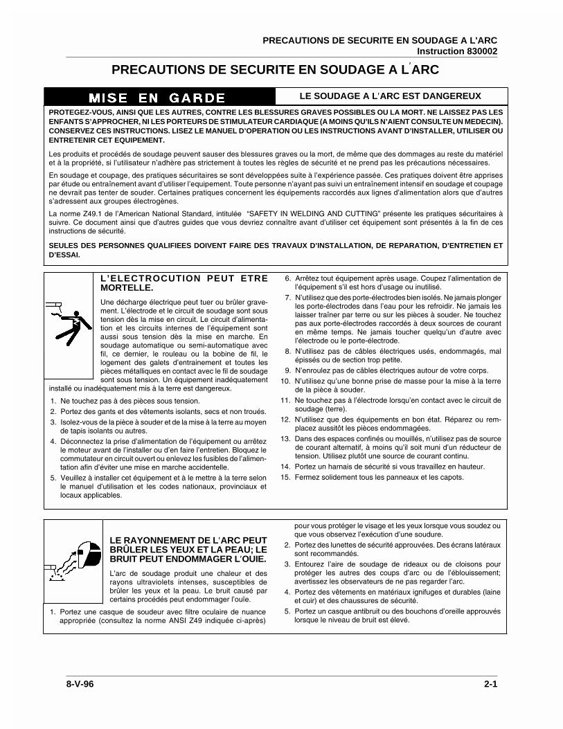
PROTEGEZ-VOUS, AINSI QUE LES AUTRES, CONTRE LES BLESSURES GRAVES POSSIBLES OU LA MORT. NE LAISSEZ PAS LESENFANTS S’APPROCHER, NI LES PORTEURS DE STIMULATEUR CARDIAQUE (A MOINS QU’ILS N’AIENT CONSULTE UN MEDECIN).CONSERVEZ CES INSTRUCTIONS. LISEZ LE MANUEL D’OPERATION OU LES INSTRUCTIONS AVANT D’INSTALLER, UTILISER OUENTRETENIR CET EQUIPEMENT.
Les produits et procédés de soudage peuvent sauser des blessures graves ou la mort, de même que des dommages au reste du matérielet à la propriété, si l’utilisateur n’adhère pas strictement à toutes les règles de sécurité et ne prend pas les précautions nécessaires.
En soudage et coupage, des pratiques sécuritaires se sont développées suite à l’expérience passée. Ces pratiques doivent être apprisespar étude ou entraînement avant d’utiliser l’equipement. Toute personne n’ayant pas suivi un entraînement intensif en soudage et coupagene devrait pas tenter de souder. Certaines pratiques concernent les équipements raccordés aux lignes d’alimentation alors que d’autress’adressent aux groupes électrogènes.
La norme Z49.1 de l’American National Standard, intitulée “SAFETY IN WELDING AND CUTTING” présente les pratiques sécuritaires àsuivre. Ce document ainsi que d’autres guides que vous devriez connaître avant d’utiliser cet équipement sont présentés à la fin de cesinstructions de sécurité.
SEULES DES PERSONNES QUALIFIEES DOIVENT FAIRE DES TRAVAUX D’INSTALLATION, DE REPARATION, D’ENTRETIEN ETD’ESSAI.
L’ELECTROCUTION PEUT ETREMORTELLE.
Une décharge électrique peut tuer ou brûler grave-ment. L’électrode et le circuit de soudage sont soustension dès la mise en circuit. Le circuit d’alimenta-tion et les circuits internes de l’équipement sontaussi sous tension dès la mise en marche. Ensoudage automatique ou semi-automatique avecfil, ce dernier, le rouleau ou la bobine de fil, lelogement des galets d’entrainement et toutes lespièces métalliques en contact avec le fil de soudagesont sous tension. Un équipement inadéquatement
installé ou inadéquatement mis à la terre est dangereux.
1. Ne touchez pas à des pièces sous tension.2. Portez des gants et des vêtements isolants, secs et non troués.3. Isolez-vous de la pièce à souder et de la mise à la terre au moyen
de tapis isolants ou autres.4. Déconnectez la prise d’alimentation de l’équipement ou arrêtez
le moteur avant de l’installer ou d’en faire l’entretien. Bloquez lecommutateur en circuit ouvert ou enlevez les fusibles de l’alimen-tation afin d’éviter une mise en marche accidentelle.
5. Veuillez à installer cet équipement et à le mettre à la terre selonle manuel d’utilisation et les codes nationaux, provinciaux etlocaux applicables.
6. Arrêtez tout équipement après usage. Coupez l’alimentation del’équipement s’il est hors d’usage ou inutilisé.
7. N’utilisez que des porte-électrodes bien isolés. Ne jamais plongerles porte-électrodes dans l’eau pour les refroidir. Ne jamais leslaisser traîner par terre ou sur les pièces à souder. Ne touchezpas aux porte-électrodes raccordés à deux sources de couranten même temps. Ne jamais toucher quelqu’un d’autre avecl’électrode ou le porte-électrode.
8. N’utilisez pas de câbles électriques usés, endommagés, malépissés ou de section trop petite.
9. N’enroulez pas de câbles électriques autour de votre corps.10. N’utilisez qu’une bonne prise de masse pour la mise à la terre
de la pièce à souder.11. Ne touchez pas à l’électrode lorsqu’en contact avec le circuit de
soudage (terre).12. N’utilisez que des équipements en bon état. Réparez ou rem-
placez aussitôt les pièces endommagées.13. Dans des espaces confinés ou mouillés, n’utilisez pas de source
de courant alternatif, à moins qu’il soit muni d’un réducteur detension. Utilisez plutôt une source de courant continu.
14. Portez un harnais de sécurité si vous travaillez en hauteur.15. Fermez solidement tous les panneaux et les capots.
PRECAUTIONS DE SECURITE EN SOUDAGE A L′ARC
LE SOUDAGE A L′ARC EST DANGEREUX
LE RAYONNEMENT DE L′ARC PEUTBRÛLER LES YEUX ET LA PEAU; LEBRUIT PEUT ENDOMMAGER L′OUIE.
L’arc de soudage produit une chaleur et desrayons ultraviolets intenses, susceptibles debrûler les yeux et la peau. Le bruit causé parcertains procédés peut endommager l’ouïe.
1. Portez une casque de soudeur avec filtre oculaire de nuanceappropriée (consultez la norme ANSI Z49 indiquée ci-après)
pour vous protéger le visage et les yeux lorsque vous soudez ouque vous observez l’exécution d’une soudure.
2. Portez des lunettes de sécurité approuvées. Des écrans latérauxsont recommandés.
3. Entourez l’aire de soudage de rideaux ou de cloisons pourprotéger les autres des coups d’arc ou de l’éblouissement;avertissez les observateurs de ne pas regarder l’arc.
4. Portez des vêtements en matériaux ignifuges et durables (laineet cuir) et des chaussures de sécurité.
5. Portez un casque antibruit ou des bouchons d’oreille approuvéslorsque le niveau de bruit est élevé.
PRECAUTIONS DE SECURITE EN SOUDAGE A L'ARCInstruction 830002
8-V-96 2-1
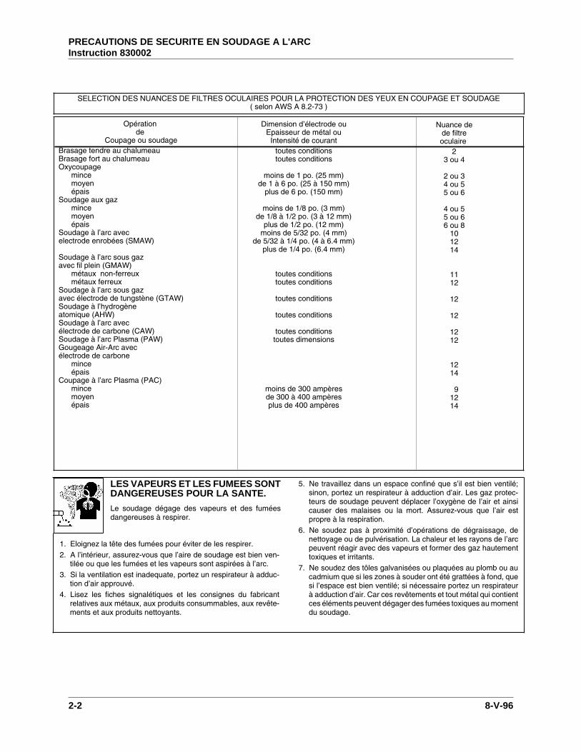
SELECTION DES NUANCES DE FILTRES OCULAIRES POUR LA PROTECTION DES YEUX EN COUPAGE ET SOUDAGE( selon AWS A 8.2-73 )
Opérationde
Coupage ou soudageBrasage tendre au chalumeauBrasage fort au chalumeauOxycoupage
mincemoyenépais
Soudage aux gazmincemoyenépais
Soudage à l’arc avecelectrode enrobées (SMAW)
Soudage à l’arc sous gazavec fil plein (GMAW)
métaux non-ferreuxmétaux ferreux
Soudage à l’arc sous gazavec électrode de tungstène (GTAW)Soudage à l’hydrogèneatomique (AHW)Soudage à l’arc avecélectrode de carbone (CAW)Soudage à l’arc Plasma (PAW)Gougeage Air-Arc avecélectrode de carbone
minceépais
Coupage à l’arc Plasma (PAC)mincemoyenépais
Dimension d’électrode ouEpaisseur de métal ou
Intensité de couranttoutes conditionstoutes conditions
moins de 1 po. (25 mm)de 1 à 6 po. (25 à 150 mm)
plus de 6 po. (150 mm)
moins de 1/8 po. (3 mm)de 1/8 à 1/2 po. (3 à 12 mm)
plus de 1/2 po. (12 mm)moins de 5/32 po. (4 mm)
de 5/32 à 1/4 po. (4 à 6.4 mm)plus de 1/4 po. (6.4 mm)
toutes conditionstoutes conditions
toutes conditions
toutes conditions
toutes conditionstoutes dimensions
moins de 300 ampèresde 300 à 400 ampèresplus de 400 ampères
Nuance dede filtreoculaire
23 ou 4
2 ou 34 ou 55 ou 6
4 ou 55 ou 66 ou 8
101214
1112
12
12
1212
1214
91214
LES VAPEURS ET LES FUMEES SONTDANGEREUSES POUR LA SANTE.
Le soudage dégage des vapeurs et des fuméesdangereuses à respirer.
1. Eloignez la tête des fumées pour éviter de les respirer.2. A l’intérieur, assurez-vous que l’aire de soudage est bien ven-
tilée ou que les fumées et les vapeurs sont aspirées à l’arc.3. Si la ventilation est inadequate, portez un respirateur à adduc-
tion d’air approuvé.4. Lisez les fiches signalétiques et les consignes du fabricant
relatives aux métaux, aux produits consummables, aux revête-ments et aux produits nettoyants.
5. Ne travaillez dans un espace confiné que s’il est bien ventilé;sinon, portez un respirateur à adduction d’air. Les gaz protec-teurs de soudage peuvent déplacer l’oxygène de l’air et ainsicauser des malaises ou la mort. Assurez-vous que l’air estpropre à la respiration.
6. Ne soudez pas à proximité d’opérations de dégraissage, denettoyage ou de pulvérisation. La chaleur et les rayons de l’arcpeuvent réagir avec des vapeurs et former des gaz hautementtoxiques et irritants.
7. Ne soudez des tôles galvanisées ou plaquées au plomb ou aucadmium que si les zones à souder ont été grattées à fond, quesi l’espace est bien ventilé; si nécessaire portez un respirateurà adduction d’air. Car ces revêtements et tout métal qui contientces éléments peuvent dégager des fumées toxiques au momentdu soudage.
PRECAUTIONS DE SECURITE EN SOUDAGE A L'ARCInstruction 830002
2-2 8-V-96
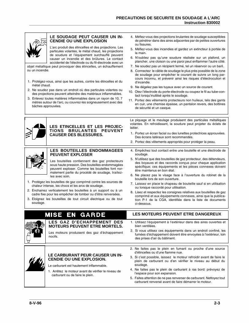
LE SOUDAGE PEUT CAUSER UN IN-CENDIE OU UNE EXPLOSION
L’arc produit des étincellies et des projections. Lesparticules volantes, le métal chaud, les projectionsde soudure et l’équipement surchauffé peuventcauser un incendie et des brûlures. Le contactaccidentel de l’électrode ou du fil-électrode avec un
objet métallique peut provoquer des étincelles, un échauffementou un incendie.
1. Protégez-vous, ainsi que les autres, contre les étincelles et dumétal chaud.
2. Ne soudez pas dans un endroit où des particules volantes oudes projections peuvent atteindre des matériaux inflammables.
3. Enlevez toutes matières inflammables dans un rayon de 10, 7mètres autour de l’arc, ou couvrez-les soigneusement avec desbâches approuvées.
4. Méfiez-vous des projections brulantes de soudage susceptiblesde pénétrer dans des aires adjacentes par de petites ouverturesou fissures.
5. Méfiez-vous des incendies et gardez un extincteur à portée dela main.
6. N’oubliez pas qu’une soudure réalisée sur un plafond, unplancher, une cloison ou une paroi peut enflammer l’autre côté.
7. Ne soudez pas un récipient fermé, tel un réservoir ou un baril.8. Connectez le câble de soudage le plus près possible de la zone
de soudage pour empêcher le courant de suivre un long par-cours inconnu, et prévenir ainsi les risques d’électrocution etd’incendie.
9. Ne dégelez pas les tuyaux avec un source de courant.10. Otez l’électrode du porte-électrode ou coupez le fil au tube-con-
tact lorsqu’inutilisé après le soudage.11. Portez des vêtements protecteurs non huileux, tels des gants
en cuir, une chemise épaisse, un pantalon revers, des bottinesde sécurité et un casque.
LES ETINCELLES ET LES PROJEC-TIONS BRULANTES PEUVENTCAUSER DES BLESSURES.
Le piquage et le meulage produisent des particules métalliquesvolantes. En refroidissant, la soudure peut projeter du éclats delaitier.
1. Portez un écran facial ou des lunettes protectrices approuvées.Des écrans latéraux sont recommandés.
2. Portez des vêtements appropriés pour protéger la peau.
LES BOUTEILLES ENDOMMAGEESPEUVENT EXPLOSER
Les bouteilles contiennent des gaz protecteurssous haute pression. Des bouteilles endommagéespeuvent exploser. Comme les bouteilles font nor-malement partie du procédé de soudage, traitez-les avec soin.
1. Protégez les bouteilles de gaz comprimé contre les sources dechaleur intense, les chocs et les arcs de soudage.
2. Enchainez verticalement les bouteilles à un support ou à uncadre fixe pour les empêcher de tomber ou d’être renversées.
3. Eloignez les bouteilles de tout circuit électrique ou de toutsoudage.
4. Empêchez tout contact entre une bouteille et une électrode desoudage.
5. N’utilisez que des bouteilles de gaz protecteur, des détendeurs,des boyauxs et des raccords conçus pour chaque applicationspécifique; ces équipements et les pièces connexes doiventêtre maintenus en bon état.
6. Ne placez pas le visage face à l’ouverture du robinet de labouteille lors de son ouverture.
7. Laissez en place le chapeau de bouteille sauf si en utilisationou lorsque raccordé pour utilisation.
8. Lisez et respectez les consignes relatives aux bouteilles de gazcomprimé et aux équipements connexes, ainsi que la publica-tion P-1 de la CGA, identifiée dans la liste de documentsci-dessous.
LES GAZ D’ECHAPPEMENT DESMOTEURS PEUVENT ETRE MORTELS.
Les moteurs produisent des gaz d’échappementnocifs.
1. Utilisez l’équipement à l’extérieur dans des aires ouvertes etbien ventilées.
2. Si vous utilisez ces équipements dans un endroit confiné, lesfumées d’échappement doivent être envoyées à l’extérieur, loindes prises d’air du bâtiment.
LES MOTEURS PEUVENT ETRE DANGEREUX
LE CARBURANT PEUR CAUSER UN IN-CENDIE OU UNE EXPLOSION.
Le carburant est hautement inflammable.
1. Arrêtez le moteur avant de vérifier le niveau decarburant ou de faire le plein.
2. Ne faites pas le plein en fumant ou proche d’une sourced’étincelles ou d’une flamme nue.
3. Si c’est possible, laissez le moteur refroidir avant de faire leplein de carburant ou d’en vérifier le niveau au début dusoudage.
4. Ne faites pas le plein de carburant à ras bord: prévoyez del’espace pour son expansion.
5. Faites attention de ne pas renverser de carburant. Nettoyez toutcarburant renversé avant de faire démarrer le moteur.
PRECAUTIONS DE SECURITE EN SOUDAGE A L'ARCInstruction 830002
8-V-96 2-3
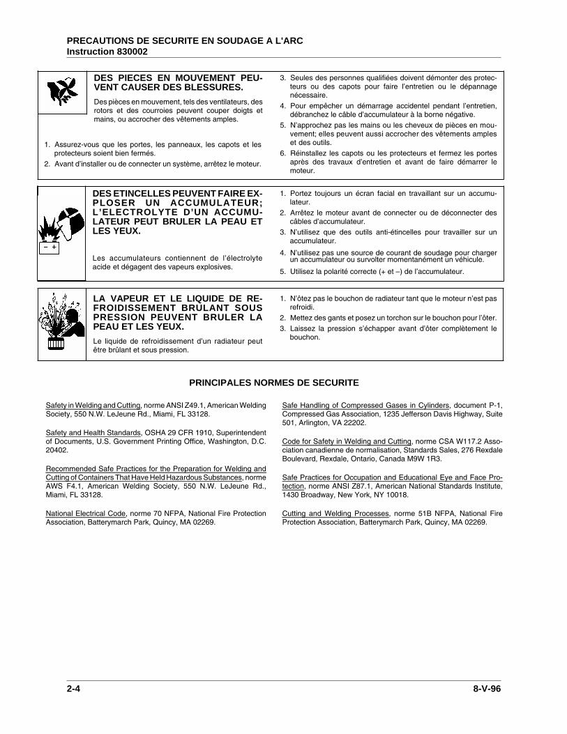
DES PIECES EN MOUVEMENT PEU-VENT CAUSER DES BLESSURES.
Des pièces en mouvement, tels des ventilateurs, desrotors et des courroies peuvent couper doigts etmains, ou accrocher des vêtements amples.
1. Assurez-vous que les portes, les panneaux, les capots et lesprotecteurs soient bien fermés.
2. Avant d’installer ou de connecter un système, arrêtez le moteur.
3. Seules des personnes qualifiées doivent démonter des protec-teurs ou des capots pour faire l’entretien ou le dépannagenécessaire.
4. Pour empêcher un démarrage accidentel pendant l’entretien,débranchez le câble d’accumulateur à la borne négative.
5. N’approchez pas les mains ou les cheveux de pièces en mou-vement; elles peuvent aussi accrocher des vêtements ampleset des outils.
6. Réinstallez les capots ou les protecteurs et fermez les portesaprès des travaux d’entretien et avant de faire démarrer lemoteur.
DES ETINCELLES PEUVENT FAIRE EX-PLOSER UN ACCUMULATEUR;L’ELECTROLYTE D’UN ACCUMU-LATEUR PEUT BRULER LA PEAU ETLES YEUX.
Les accumulateurs contiennent de l’électrolyteacide et dégagent des vapeurs explosives.
1. Portez toujours un écran facial en travaillant sur un accumu-lateur.
2. Arrêtez le moteur avant de connecter ou de déconnecter descâbles d’accumulateur.
3. N’utilisez que des outils anti-étincelles pour travailler sur unaccumulateur.
4. N’utilisez pas une source de courant de soudage pour chargerun accumulateur ou survolter momentanément un véhicule.
5. Utilisez la polarité correcte (+ et –) de l’accumulateur.
LA VAPEUR ET LE LIQUIDE DE RE-FROIDISSEMENT BRULANT SOUSPRESSION PEUVENT BRULER LAPEAU ET LES YEUX.
Le liquide de refroidissement d’un radiateur peutêtre brûlant et sous pression.
1. N’ôtez pas le bouchon de radiateur tant que le moteur n’est pasrefroidi.
2. Mettez des gants et posez un torchon sur le bouchon pour l’ôter.3. Laissez la pression s’échapper avant d’ôter complètement le
bouchon.
PRINCIPALES NORMES DE SECURITE
Safety in Welding and Cutting, norme ANSI Z49.1, American WeldingSociety, 550 N.W. LeJeune Rd., Miami, FL 33128.
Safety and Health Standards, OSHA 29 CFR 1910, Superintendentof Documents, U.S. Government Printing Office, Washington, D.C.20402.
Recommended Safe Practices for the Preparation for Welding andCutting of Containers That Have Held Hazardous Substances, normeAWS F4.1, American Welding Society, 550 N.W. LeJeune Rd.,Miami, FL 33128.
National Electrical Code, norme 70 NFPA, National Fire ProtectionAssociation, Batterymarch Park, Quincy, MA 02269.
Safe Handling of Compressed Gases in Cylinders, document P-1,Compressed Gas Association, 1235 Jefferson Davis Highway, Suite501, Arlington, VA 22202.
Code for Safety in Welding and Cutting, norme CSA W117.2 Asso-ciation canadienne de normalisation, Standards Sales, 276 RexdaleBoulevard, Rexdale, Ontario, Canada M9W 1R3.
Safe Practices for Occupation and Educational Eye and Face Pro-tection, norme ANSI Z87.1, American National Standards Institute,1430 Broadway, New York, NY 10018.
Cutting and Welding Processes, norme 51B NFPA, National FireProtection Association, Batterymarch Park, Quincy, MA 02269.
PRECAUTIONS DE SECURITE EN SOUDAGE A L'ARCInstruction 830002
2-4 8-V-96
DESCRIPTION OF EQUIPMENT
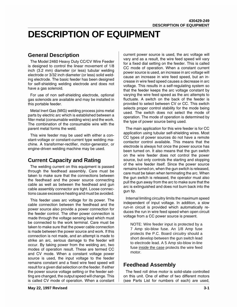
General DescriptionThe Model 2460 Heavy Duty CC/CV Wire Feeder
is designed to control the linear movement of 1/8inch (3.2 mm) diameter (or less) tubular weldingelectrode or 3/32 inch diameter (or less) solid weld-ing electrode. The basic feeder has been designedfor self-shielding welding electrode and does nothave a gas solenoid.
For use of non self-shielding electrode, optionalgas solenoids are available and may be installed inthis portable feeder.
Metal Inert Gas (MIG) welding process joins metalparts by electric arc which is established between afiller metal (consumable welding wire) and the work.The combination of the consumable wire with theparent metal forms the weld.
This wire feeder may be used with either a con-stant-voltage or constant-current type welding ma-chine. A transformer-rectifier, motor-generator, orengine-driven welding machine may be used.
Current Capacity and RatingThe welding current on this equipment is passed
through the feedhead assembly. Care must betaken to make sure that the connections betweenthe feedhead and the power source connectingcable as well as between the feedhead and guncable assembly connector are tight. Loose connec-tions cause excessive heating and must be avoided.
This feeder uses arc voltage for its power. Thecable connection between the feedhead and thepower source also provide a power connection forthe feeder control. The other power connection ismade through the voltage sensing lead which mustbe connected to the work terminal. Care must betaken to make sure that the power cable connectionis made between the power source and work. If thisconnection is not made, and an attempt is made tostrike an arc, serious damage to the feeder willoccur. By taking power from the welding arc, twomodes of operation result. These are termed CCand CV mode. When a constant voltage powersource is used, the input voltage to the feederremains constant and a fixed wire feed speed willresult for a given dial selection on the feeder. If eitherthe power source voltage setting or the feeder set-ting are changed, the output speed will change. Thisis called CV mode of operation. When a constant
current power source is used, the arc voltage willvary and as a result, the wire feed speed will varyfor a fixed dial setting on the feeder. This is calledCC mode of operation. When a constant currentpower source is used, an increase in arc voltage willcause an increase in wire feed speed, but an in-crease in wire feed speed causes a decrease in arcvoltage. This results in a self-regulating system sothat the feeder keeps the arc voltage constant byvarying the wire feed speed as the arc attempts tofluctuate. A switch on the back of the feeder isprovided to select between CV or CC. This switchselects proper control stability for the mode beingused. The switch does not select the mode ofoperation. The mode of operation is determined bythe type of power source being used.
The main application for this wire feeder is for CCapplication using tubular self-shielding wires. MostCC types of power sources do not have a remotecontactor control available. This means that theelectrode is always hot once the power source hasbeen turned on. It also means that the gun switchon the wire feeder does not control the powersource, but only controls the starting and stoppingof the wire feeder itself. Since the power sourceremains turned on, when the gun switch is released,care must be taken when terminating the arc. Whenthe gun switch is released, the operator must alsopull the gun away from the arc to make sure that thearc is extinguished and does not burn back into thegun tip.
Internal limiting circuitry limits the maximum speedindependent of input voltage. In addition, a slowrun-in circuit is provided which automatically re-duces the run in wire feed speed when open circuitvoltage from a CC power source is present.
NOTE: Wire feeder input is protected by a7 Amp slo-blow fuse. An 1/8 Amp fuseprotects the P.C. Board circuitry should ashort develop between the gun switch leadto electrode lead. A 5 Amp slo-blow in-linefuse inside the case protects the wire feedmotor.
Feedhead AssemblyThe feed roll drive motor is solid-state controlled
on this unit. One of either of two different motors(see Parts List for numbers of each) are used,
430429-249DESCRIPTION OF EQUIPMENT
May 22, 1997 Revised 3-1
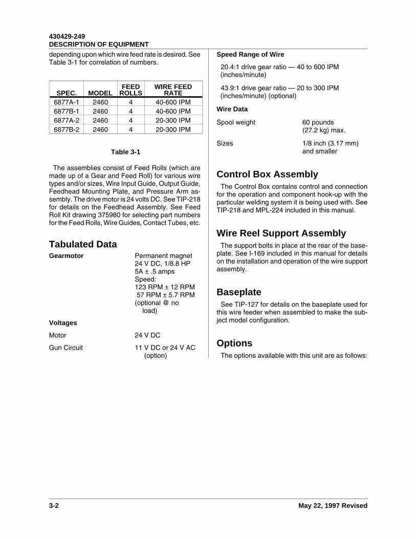
depending upon which wire feed rate is desired. SeeTable 3-1 for correlation of numbers.
The assemblies consist of Feed Rolls (which aremade up of a Gear and Feed Roll) for various wiretypes and/or sizes, Wire Input Guide, Output Guide,Feedhead Mounting Plate, and Pressure Arm as-sembly. The drive motor is 24 volts DC. See TIP-218for details on the Feedhead Assembly. See FeedRoll Kit drawing 375980 for selecting part numbersfor the Feed Rolls, Wire Guides, Contact Tubes, etc.
Tabulated DataGearmotor Permanent magnet
24 V DC, 1/8.8 HP5A ± .5 ampsSpeed:123 RPM ± 12 RPM57 RPM ± 5.7 RPM
(optional @ noload)
Voltages
Motor 24 V DC
Gun Circuit 11 V DC or 24 V AC(option)
Speed Range of Wire
20.4:1 drive gear ratio — 40 to 600 IPM(inches/minute)
43.9:1 drive gear ratio — 20 to 300 IPM(inches/minute) (optional)
Wire Data
Spool weight 60 pounds(27.2 kg) max.
Sizes 1/8 inch (3.17 mm)and smaller
Control Box AssemblyThe Control Box contains control and connection
for the operation and component hook-up with theparticular welding system it is being used with. SeeTIP-218 and MPL-224 included in this manual.
Wire Reel Support AssemblyThe support bolts in place at the rear of the base-
plate. See I-169 included in this manual for detailson the installation and operation of the wire supportassembly.
BaseplateSee TIP-127 for details on the baseplate used for
this wire feeder when assembled to make the sub-ject model configuration.
OptionsThe options available with this unit are as follows:
SPEC. MODELFEED
ROLLSWIRE FEED
RATE6877A-1 2460 4 40-600 IPM6877B-1 2460 4 40-600 IPM6877A-2 2460 4 20-300 IPM6877B-2 2460 4 20-300 IPM
Table 3-1
430429-249DESCRIPTION OF EQUIPMENT
3-2 May 22, 1997 Revised
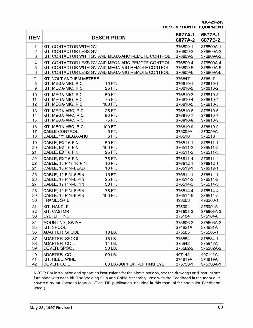
ITEM DESCRIPTION6877A-16877A-2
6877B-16877B-2
123
KIT, CONTACTOR WITH GVKIT, CONTACTOR LESS GVKIT, CONTACTOR WITH GV AND MEGA-ARC REMOTE CONTROL
376809-1376809-2376809-3
376809A-1376809A-2376809A-3
456
KIT, CONTACTOR LESS GV AND MEGA-ARC REMOTE CONTROLKIT, CONTACTOR WITH GV AND MEGA-MIG REMOTE CONTROLKIT, CONTACTOR LESS GV AND MEGA-MIG REMOTE CONTROL
376809-4376809-5376809-6
376809A-4376809A-5376809A-6
789
KIT, VOLT AND IPM METERSKIT, MEGA-MIG, R.C. 15 FT.KIT, MEGA-MIG, R.C. 25 FT.
376847376810-1376810-2
376847376810-1376810-2
101112
KIT, MEGA-MIG, R.C. 50 FT.KIT, MEGA-MIG, R.C. 75 FT.KIT, MEGA-MIG, R.C. 100 FT.
376810-3376810-4376810-5
376810-3376810-4376810-5
131415
KIT, MEGA-ARC, R.C. 25 FT.KIT, MEGA-ARC, R.C. 50 FT.KIT, MEGA-ARC, R.C. 75 FT.
376810-6376810-7376810-8
376810-6376810-7376810-8
161718
KIT, MEGA-ARC, R.C. 100 FT.CABLE CONTROL 6 FT.CABLE, “Y” MEGA-ARC 6 FT.
376810-9373059A376510
376810-9373059A376510
192021
CABLE, EXT 6 PIN 50 FT.CABLE, EXT 6 PIN 100 FT.CABLE, EXT 6 PIN 25 FT.
376511-1376511-2376511-3
376511-1376511-2376511-3
222324
CABLE, EXT 6 PIN 75 FT.CABLE, 19 PIN–10 PIN 10 FT.CABLE, 10 PIN–LEAD 10 FT.
376511-4376512-1376513-1
376511-4376512-1376513-1
252627
CABLE, 19 PIN–6 PIN 15 FT.CABLE, 19 PIN–6 PIN 25 FT.CABLE, 19 PIN–6 PIN 50 FT.
376514-1376514-2376514-3
376514-1376514-2376514-3
282930
CABLE, 19 PIN–6 PIN 75 FT.CABLE, 19 PIN–6 PIN 100 FT.FRAME, SKID
376514-4376514-5493263
376514-4376514-5493263-1
313233
KIT, HANDLEKIT, CASTOREYE, LIFTING
375994375605-2375104
375994A375605A-2375104A
343536
MOUNTING, SWIVELKIT, SPOOLADAPTER, SPOOL 10 LB.
375606-2374831A375585
375606A-2374831A375585-1
373839
ADAPTER, SPOOL 15 LB.ADAPTER, COIL 14 LB.COVER, SPOOL 30 LB.
375584375942375582-2
375584-1375942A375582A-2
404142
ADAPTER, COIL 60 LB.KIT, REEL, WIRECOVER, COIL 60 LB./SUPPORT/LIFTING EYE
407142374819A375733-1
407142A374819A375733A-1
NOTE: For installation and operation instructions for the above options, see the drawings and instructionsfurnished with each kit. The Welding Gun and Cable Assembly used with the Feedhead in the manual iscovered by an Owner’s Manual. (See TIP publication included in this manual for particular Feedheadused.)
430429-249DESCRIPTION OF EQUIPMENT
May 22, 1997 Revised 3-3

This page intentionally left blank.
430429-249DESCRIPTION OF EQUIPMENT
3-4 May 22, 1997 Revised
OPERATION
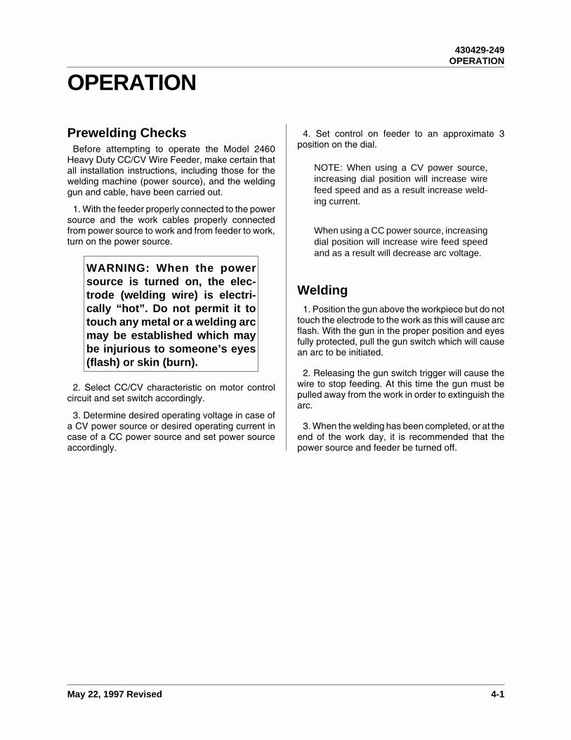
Prewelding ChecksBefore attempting to operate the Model 2460
Heavy Duty CC/CV Wire Feeder, make certain thatall installation instructions, including those for thewelding machine (power source), and the weldinggun and cable, have been carried out.
1. With the feeder properly connected to the powersource and the work cables properly connectedfrom power source to work and from feeder to work,turn on the power source.
WARNING: When the powersource is turned on, the elec-trode (welding wire) is electri-cally “hot”. Do not permit it totouch any metal or a welding arcmay be established which maybe injurious to someone’s eyes(flash) or skin (burn).
2. Select CC/CV characteristic on motor controlcircuit and set switch accordingly.
3. Determine desired operating voltage in case ofa CV power source or desired operating current incase of a CC power source and set power sourceaccordingly.
4. Set control on feeder to an approximate 3position on the dial.
NOTE: When using a CV power source,increasing dial position will increase wirefeed speed and as a result increase weld-ing current.
When using a CC power source, increasingdial position will increase wire feed speedand as a result will decrease arc voltage.
Welding1. Position the gun above the workpiece but do not
touch the electrode to the work as this will cause arcflash. With the gun in the proper position and eyesfully protected, pull the gun switch which will causean arc to be initiated.
2. Releasing the gun switch trigger will cause thewire to stop feeding. At this time the gun must bepulled away from the work in order to extinguish thearc.
3. When the welding has been completed, or at theend of the work day, it is recommended that thepower source and feeder be turned off.
430429-249OPERATION
May 22, 1997 Revised 4-1

This page intentionally left blank.
430429-249OPERATION
4-2 May 22, 1997 Revised

PARTS LIST
Equipment IdentificationAll identification numbers as described in the In-
troduction chapter must be furnished when orderingparts or making inquiries. This information is usuallyfound on the nameplate attached to the equipment.Be sure to include any dash numbers following theSpecification or Assembly numbers.
How To Use This Parts ListThe Parts List is a combination of an illustration
(Figure Number) and a corresponding list of partswhich contains a breakdown of the equipment intoassemblies, subassemblies, and detail parts. Allparts of the equipment are listed except for commer-cially available hardware, bulk items such as wire,cable, sleeving, tubing, etc., and permanently at-tached items which are soldered, riveted, or welded
to another part. The part descriptions may beindented to show part relationships.
To determine the part number, description, quan-tity, or application of an item, simply locate the itemin question from the illustration and refer to thatitem number in the corresponding Parts List.
An “Application Code” is used to distinguish partsthat are applicable only to certain Specificationsand/or Assemblies. This code is found in the right-most column of the Parts List. If an item in the PartsList applies to all Specifications or Assemblies, theword “ALL” will be in the Application Code column.Refer to the following list to determine the appro-priate Application Codes for the Specifications orAssemblies covered by this manual. If only theassembly or specification number is listed, the useof an Application Code does not apply to thismanual.
SPECIFICATION NUMBER APPLICATION CODE
6877A-1 A
6877A-2 B
6877B-1 C
6877B-2 D
430429-249Troy, Ohio 45373 PARTS LIST
November 2, 1999 Revised 5-1
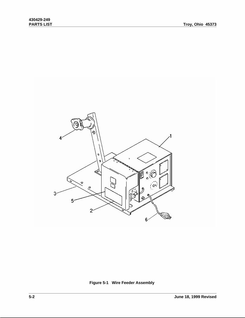
Figure 5-1 Wire Feeder Assembly
430429-249PARTS LIST Troy, Ohio 45373
5-2 June 18, 1999 Revised

S-6877A-1 Wire Feeder, CC/CV Operation4-Roll Drive, 40-600 IPM 1 A
S-6877A-2 Wire Feeder, CC/CV Operation4-Roll Drive, 20-300 IPM 1 B
S-6877B-1 Wire Feeder, CC/CV Operation4-Roll Drive, 40-600 IPM 1 C
S-6877B-2 Wire Feeder, CC/CV Operation4-Roll Drive, 20-300 IPM 1 D
1 376783B . Box - Control Assembly(For Details See Figure 5-2) 1 AB
376783B-1 . Box - Control Assembly(For Details See Figure 5-2) 1 CD
2 376799A-1 . Feedhead - Assembly 40-600 IPM(For Details See MPL-224) 1 A
376799A-3 . Feedhead - Assembly 40-600 IPM(For Details See MPL-224) 1 C
376799A-2 . Feedhead - Assembly 20-300 IPM(For Details See MPL-224) 1 B
376799A-4 . Feedhead - Assembly 20-300 IPM(For Details See MPL-224) 1 D
3 375769-1 . Base 1 AB375769-4 . Base 1 CD
4 374818A-1 . Support - Wire Spool Assembly(For Details See I-169) 1 AB
374818A-9 . Support - Wire Spool Assembly(For Details See I-169) 1 CD
— 376827 List - Field Installable Options Ref. All5 870087-1 Label - Thermal Arc 2 All6 870194-1 Cable - Assy 1 All
— Not Illustrated
Item Part Description Qty Application
No Number per Code
Assy
Parts List for Figure 5-1
430429-249Troy, Ohio 45373 PARTS LIST
November 2, 1999 Revised 5-3
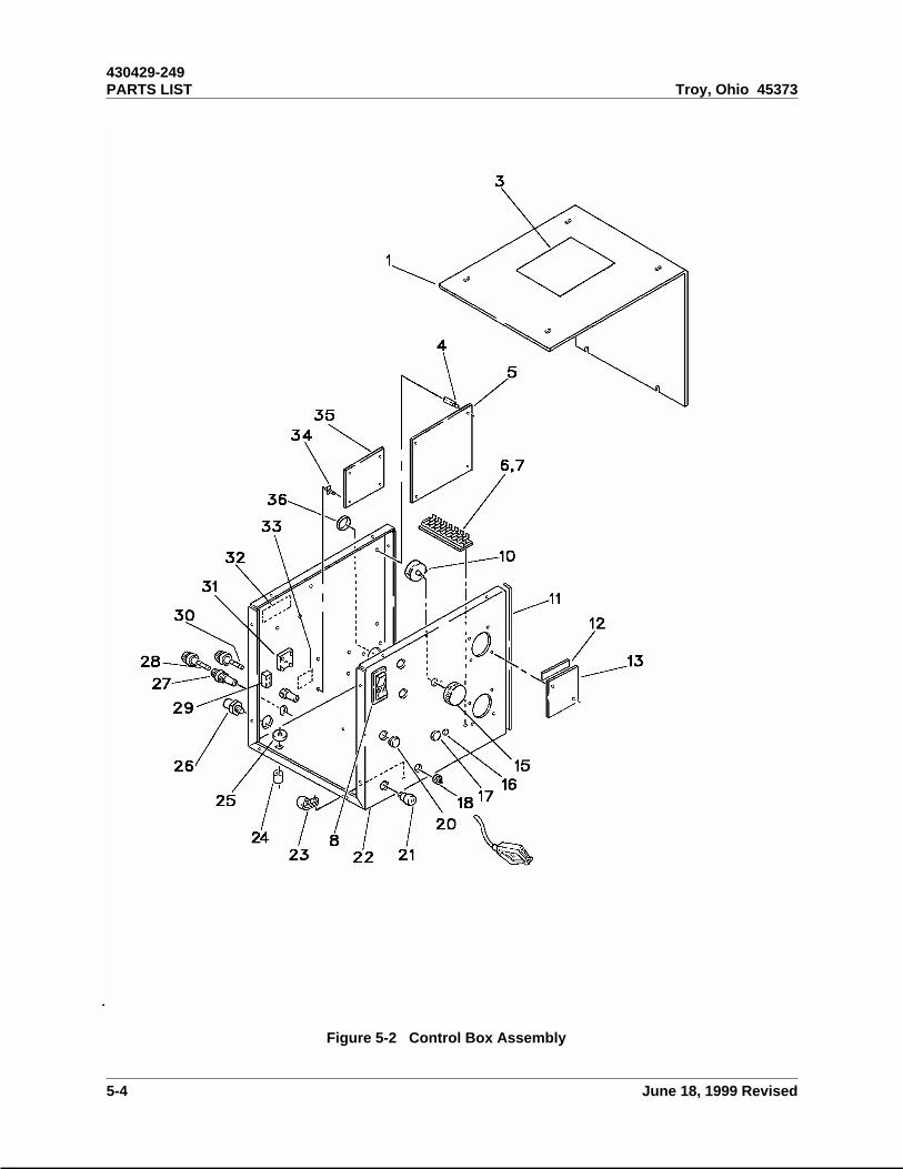
Figure 5-2 Control Box Assembly
430429-249PARTS LIST Troy, Ohio 45373
5-4 June 18, 1999 Revised
376826 Cover - Control Box Assembly 1 AB376826-1 Cover - Control Box Assembly 1 CD
1 376782-1 . Cover - Control Box 1 AB376782-2 . Cover - Control Box 1 CD
2 Deleted3 204036 . Label - Precautionary 1 All
376783B Box - Control Assembly 1 AB376783B-1 Box - Control Assembly 1 CD
4 405535-2 . Support - P.C. Board 4 All5 376807C . Board - P.C., Motor Control 1 All6 401937-2 . Block - Terminal, 20 Amp, 8 Station 1 All7 407146 . Label - Terminal Block 1 All8 403704-1 . Switch - Rocker, ON/OFF 1 All9 Deleted10 406926-3 . Potentiometer - 10K, 2 W 1 All11 40209 . Strip - Weather, 1/16 x 1/2 68-1/4" All12 40207 . Strip - Weather, 1/16 x 1/4 15-3/4" All13 376718 . Plate - Cover 2 AB
376718-1 . Plate - Cover 2 CD14 Deleted15 406806 . Knob - Control 1 AB
406806-3 . Knob - Control 1 CD16 408246-1 . Clip - Nylon 7 All17 403091-4 . Plug - Hole, Plastic 1 All18 402037-3 . Grommet 1 All19 . Deleted20 403091-2 . Plug - Hole, Plastic 2 All21 405576-1 . Bushing - Terminal 1 All22 376711B-1 . Wrapper - Control Box 1 AB
376711B-2 . Wrapper - Control Box 1 CD23 W-10051-2 . Clamp - Wire Plastic 1 All24 409838 . Grommet - Mtg. 4 All25 409837 . Spacer - Nylon 4 All26 371635 . Adapter - Gas R.H. 1 All27 408242-1 . Fuseholder 2 All
2 28 401972-5 . Fuse - Slo-Blow, 7 Amp 1 All
— Not Illustrated
Item Part Description Qty Application
No Number per Code
Assy
Parts List for Figure 5-2
430429-249Troy, Ohio 45373 PARTS LIST
November 2, 1999 Revised 5-5

29 407097-1 . Switch - Toggle 1 All— 403031 . Seal - Switch 1 All— 408243-1 . Boot - Switch 1 All30 401972-2 . Fuse - 5 Amp, Slow Blow 1 All— 406008-13 . Receptacle, 6 Position 1 All— 406008-3 . Receptacle, 12 Position 1 All— 406008-10 . Receptacle, 4 Position 1 All— 406009-1 . Plug - Keying 3 All31 404065-2 . Rectifier - Bridge 1 All32 407961A-1 . Nameplate - Prod. Info. 1 All33 170656 . Label - Fuse 1 AB34 405535-5 . Support - P.C. Board 4 All35 376507 . Board - P.C. Gas Valve 1 All36 403091-11 . Plug - Hole, Plastic 1 All
— Not Illustrated
Item Part Description Qty Application
No Number per Code
Assy
Parts List for Figure 5-2
430429-249PARTS LIST Troy, Ohio 45373
5-6 June 18, 1999 Revised
CONTROL BOX ASSEMBLY NO. 376783A & 376783B
DESCRIPTION, INSTALLATION, OPERATION AND MAINTENANCE
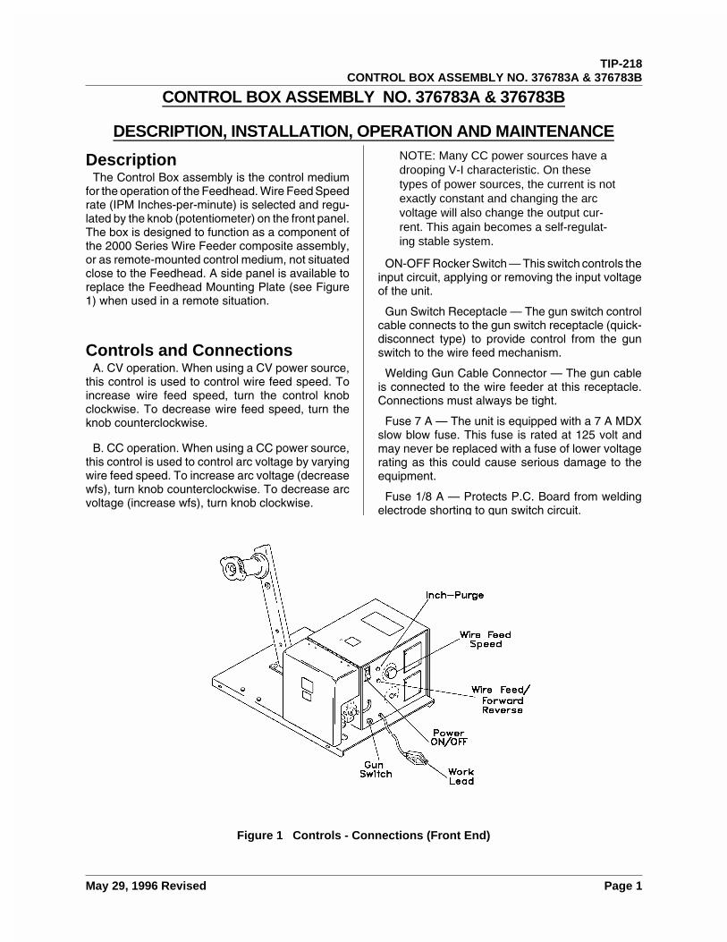
DescriptionThe Control Box assembly is the control medium
for the operation of the Feedhead. Wire Feed Speedrate (IPM Inches-per-minute) is selected and regu-lated by the knob (potentiometer) on the front panel.The box is designed to function as a component ofthe 2000 Series Wire Feeder composite assembly,or as remote-mounted control medium, not situatedclose to the Feedhead. A side panel is available toreplace the Feedhead Mounting Plate (see Figure1) when used in a remote situation.
Controls and ConnectionsA. CV operation. When using a CV power source,
this control is used to control wire feed speed. Toincrease wire feed speed, turn the control knobclockwise. To decrease wire feed speed, turn theknob counterclockwise.
B. CC operation. When using a CC power source,this control is used to control arc voltage by varyingwire feed speed. To increase arc voltage (decreasewfs), turn knob counterclockwise. To decrease arcvoltage (increase wfs), turn knob clockwise.
NOTE: Many CC power sources have adrooping V-I characteristic. On thesetypes of power sources, the current is notexactly constant and changing the arcvoltage will also change the output cur-rent. This again becomes a self-regulat-ing stable system.
ON-OFF Rocker Switch — This switch controls theinput circuit, applying or removing the input voltageof the unit.
Gun Switch Receptacle — The gun switch controlcable connects to the gun switch receptacle (quick-disconnect type) to provide control from the gunswitch to the wire feed mechanism.
Welding Gun Cable Connector — The gun cableis connected to the wire feeder at this receptacle.Connections must always be tight.
Fuse 7 A — The unit is equipped with a 7 A MDXslow blow fuse. This fuse is rated at 125 volt andmay never be replaced with a fuse of lower voltagerating as this could cause serious damage to theequipment.
Fuse 1/8 A — Protects P.C. Board from weldingelectrode shorting to gun switch circuit.
Figure 1 Controls - Connections (Front End)
TIP-218CONTROL BOX ASSEMBLY NO. 376783A & 376783B
May 29, 1996 Revised Page 1
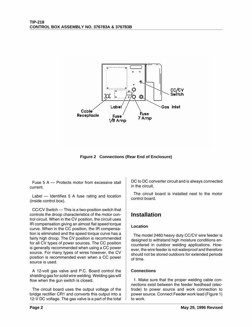
Fuse 5 A — Protects motor from excessive stallcurrent.
Label — Identifies 5 A fuse rating and location(inside control box).
CC/CV Switch — This is a two-position switch thatcontrols the droop characteristics of the motor con-trol circuit. When in the CV position, the circuit usesIR compensation giving an almost flat speed torquecurve. When in the CC position, the IR compensa-tion is eliminated and the speed torque curve has afairly high droop. The CV position is recommendedfor all CV types of power sources. The CC positionis generally recommended when using a CC powersource. For many types of wires however, the CVposition is recommended even when a CC powersource is used.
A 12-volt gas valve and P.C. Board control theshielding gas for solid wire welding. Welding gas willflow when the gun switch is closed.
The circuit board uses the output voltage of thebridge rectifier CR1 and converts this output into a12-V DC voltage. The gas valve is a part of the total
DC to DC converter circuit and is always connectedin the circuit.
The circuit board is installed next to the motorcontrol board.
Installation
Location
The model 2460 heavy duty CC/CV wire feeder isdesigned to withstand high moisture conditions en-countered in outdoor welding applications. How-ever, the wire feeder is not waterproof and thereforeshould not be stored outdoors for extended periodsof time.
Connections
1. Make sure that the proper welding cable con-nections exist between the feeder feedhead (elec-trode) to power source and work connection topower source. Connect Feeder work lead (Figure 1)to work.
Figure 2 Connections (Rear End of Enclosure)
TIP-218CONTROL BOX ASSEMBLY NO. 376783A & 376783B
Page 2 May 29, 1996 Revised
2. Attach the gun and cable to the wire feeder byfollowing instructions found in the Owner’s Manualfor the Gun and Cable assembly.
WARNING: The welding elec-trode is electrically “Hot”. Elec-trode contact to workpiece willcause an arc with the wire feederconnected to the workpiece andgun switch depressed — feedmotor will run feeding “HOT”electrode.
Operation
Theory of OperationRefer to Connection Diagram 376784A
With the wire feeder connected to the weldingelectrode and the work terminal, turn the powersource and wire feeder on. Power is supplied intoBridge rectifier CR1. Power on the output side of theCR1 is fed to the motor control board with the properpolarity independent of the welding polarity.
When the welding gun switch (S4) is closed, itenergizes the proper components on the PC Boardand causes the motor to run. When the gun switchis opened, it removes power from the motor andshorts the armature to provide dynamic braking ofthe motor.
When the CC/CV switch (S5) is open, IR compen-sation is used on the motor control circuit. When S5is closed, the IR compensation circuit is not active.
Terminal strip TB1 is used to connect variousoptions to the feeder.
Switch S1 is used to turn the power into the feederon or off.
Resistor R1 is the control potentiometer for the unitwhich varies the output speed.
The motor control circuit on this feeder is a DC toDC converter circuit. It uses the power supply output
voltage and changes it to the proper DC voltagerequired to operate the motor. The motor is part ofthe operating circuit, and the circuit will not operateproperly if the motor is removed.
The circuit is designed for continuous operationwhen the input voltage is 30 volts or below. ManyCC power sources have an open circuit voltage of60 to 100 volts. Under these input conditions, thecircuit will operate and the motor will run. Thiscondition may exist for a period long enough to feedwire through the gun when wire spools are changed,etc., but the motor must never be allowed to operatewith open circuit voltage for prolonged periods oftime.
Options
1. Remote Contactor Control Option — This optionis externally located and connects to the feeder bymeans of a control cable which is added to thefeeder. When this option is installed, a relay isadded to the feeder and a 24-V AC gas valve optionis available.
The remote box requires 115-V AC input and inturn provides 24 V AC to the feeder as well as acontactor control relay closure to the power source.The 24 V AC is also used to allow for inching of thewire feed motor.
2. A voltmeter kit as well as an inches per minutekit are available for this unit.
3. A remote arc voltage/current control is alsoavailable which allows the user to adjust the powersource at the feeder.
Maintenance
Cleaning of the Unit
Periodically remove a side panel of the cabinet,and blow out the interior with clean, dry, com-pressed air of not more than 25 psi (172 kPa)pressure. Do not strike any of the components withthe air hose nozzle.
TIP-218CONTROL BOX ASSEMBLY NO. 376783A & 376783B
May 29, 1996 Revised Page 3
TroubleshootingThe following chart contains information which can be used to diagnose and correct unsatisfactory operationor failure of various components of the unit. Each symptom of trouble is followed by a list of probable causesand procedures to correct them.
Wire does not feed, open-circuit voltage is normal
Switch on Feeder not on or bad
Check and correct.
Fuse open on Feeder
Check and replace.
Work lead not connected
Check and connect.
Cables from Power Sources not properly connected
Check and connect.
Gun switch defective
Check for proper operation.
Feed rolls not properly tightened
Correct situation.
Bad PC board on feeder
Replace.
5 A internal fuse blown
Replace fuse.
Erratic weld output
Ground clamp loose at WORK connection
Check ground clamp for secure attachment.
Gun liner dirty
Check gun liner and replace if necessary.
Voltage/current and feeder settings are not correct
Readjust as necessary.
Improper wire for gas less welding
Change to proper wire.
Wire feed motor operates, but wire does not feed
Too little pressure on wire feed roll
Increase pressure adjustment.
Incorrect wire groove
Check wire size stamped on outside of feed roll. Match to wire size.
TIP-218CONTROL BOX ASSEMBLY NO. 376783A & 376783B
Page 4 May 29, 1996 Revised
Wire spool tension too great
Loosen adjusting screw.
Restriction in gun or cable assembly
Examine cable, gun, and current contact tube (tip) for damage and correct size.Make sure correct contact tube and liner is being used.
Welding current or voltage not stable
Wire slipping in rolls
Readjust pressure on the drive roll pressure arm.
Restriction in gun cable or gun
See Welding Gun and Cable Description and Maintenance.
Wrong size liner or contact tube
Match liner and contact tube to electrode wire size.
Incorrect voltage adjustment for selected wire speed on the welding machine
Readjust. See Welding Guide in Operation section.
Loose connection on the welding leads or work table
Check and tighten all connections.
Wire wraps around the drive roll
Too much feed roll pressure
Decrease the pressure adjustment on the drive roll pressure arm.
Incorrect liner or contact tube
Make sure that liner and/or contact tube is correct for the size of wire being fed.
No speed control
Broken or loose wires in wire feed control circuit
Correct by checking all connections.
Bad PC board
Replace.
Bad wire feed speed control potentiometer
Replace.
No gas flow
Gas valve not energizing
Broken lead to valve.
Bad PC board
Replace.
Open gas valve coil
Replace gas valve.
TIP-218CONTROL BOX ASSEMBLY NO. 376783A & 376783B
May 29, 1996 Revised Page 5

This page intentionally left blank.
TIP-218CONTROL BOX ASSEMBLY NO. 376783A & 376783B
Page 6 May 29, 1996 Revised
FEEDHEAD ASSEMBLY NO. 376799A-1, -2, -3, -4
DESCRIPTION, INSTALLATION, OPERATION AND MAINTENANCE
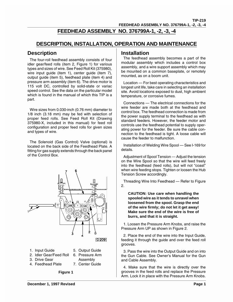
DescriptionThe four-roll feedhead assembly consists of four
idler gear/feed rolls (item 2, Figure 1) for varioustypes and sizes of wire. See Feed Roll Kit (375980),wire input guide (item 1), center guide (item 7),output guide (item 5), feedhead plate (item 4) andpressure arm assembly (item 6). The drive motor is115 volt DC, controlled by solid-state or variacspeed control. See the data on the particular modelwhich is found in the manual of which this TIP is apart.
Wire sizes from 0.030-inch (0.76 mm) diameter to1/8 inch (3.18 mm) may be fed with selection ofproper feed rolls. See Feed Roll Kit (Drawing375980-X, included in this manual) for feed rollconfiguration and proper feed rolls for given sizesand types of wire.
The Solenoid (Gas Control) Valve (optional) islocated on the back side of the Feedhead Plate. Afitting for gas supply extends through the back panelof the Control Box.
InstallationThe feedhead assembly becomes a part of the
modular assembly which includes a control boxassembly, and a wire support assembly which maybe mounted on a common baseplate, or remotelymounted, as on a boom unit.
Location — For best operating characteristics andlongest unit life, take care in selecting an installationsite. Avoid locations exposed to dust, high ambienttemperature, or corrosive fumes.
Connections — The electrical connections for thewire feeder are made both at the feedhead andcontrol box. The feedhead connection is made fromthe power supply terminal to the feedhead as withstandard feeders. However, the feeder motor andcontrols use the feedhead potential to supply oper-ating power for the feeder. Be sure the cable con-nection to the feedhead is tight. A loose cable willcause the feeder to malfunction.
Installation of Welding Wire Spool — See I-169 fordetails.
Adjustment of Spool Tension — Adjust the tensionon the Wire Spool so that the wire will feed freelyinto the feedhead (feed rolls), but will not “coast”when wire feeding stops. Tighten or loosen the HubTension Screw accordingly.
Threading Wire Into Feedhead — Refer to Figure2.
CAUTION: Use care when handling thespooled wire as it tends to unravel whenloosened from the spool. Grasp the endof the wire firmly; do not let it get away!Make sure the end of the wire is free ofburrs, and that it is straight.
1. Loosen the Pressure Arm Knobs, and raise thePressure Arm UP as shown in Figure 2.
2. Place the end of the wire into the Input Guide,feeding it through the guide and over the feed rollgrooves.
3. Pass the wire into the Output Guide and on intothe Gun Cable. See Owner’s Manual for the Gunand Cable Assembly.
4. Make sure that the wire is directly over thegrooves in the feed rolls and replace the PressureArm. Lock it in place with the Pressure Arm Knobs.
Figure 1
1. Input Guide2. Idler Gear/Feed Roll3. Drive Gear4. Feedhead Plate
5. Output Guide6. Pressure Arm
Assembly7. Center Guide
TIP-219FEEDHEAD ASSEMBLY NO. 376799A-1, -2, -3, -4
December 1, 1997 Revised Page 1
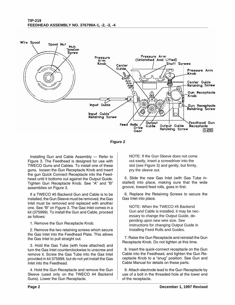
Installing Gun and Cable Assembly — Refer toFigure 3. The Feedhead is designed for use withTWECO Guns and Cables. To install one of theseguns, loosen the Gun Receptacle Knob and insertthe gun Quick Connect Receptacle into the Feed-head until it bottoms out against the Output Guide.Tighten Gun Receptacle Knob. See “A” and “B”assemblies on Figure 3.
If a TWECO #5 Backend Gun and Cable is to beinstalled, the Gun Sleeve must be removed, the GasInlet must be removed and replaced with anotherone. See “B” on Figure 3. The Gas Inlet comes in akit (375999). To install the Gun and Cable, proceedas follows:
1. Remove the Gun Receptacle Knob.
2. Remove the two retaining screws which securethe Gas Inlet into the Feedhead Plate. This allowsthe Gas Inlet to pull straight out.
3. Hold the Gas Tube (with hose attached) andturn the Gas Inlet counterclockwise to unscrew andremove it. Screw the Gas Tube into the Gas Inletprovided in kit 375999, but do not yet install the GasInlet into the Feedhead.
4. Hold the Gun Receptacle and remove the GunSleeve (used only on the TWECO #4 BackendGuns). Lower the Gun Receptacle.
NOTE: If the Gun Sleeve does not comeout easily, insert a screwdriver into theslot (see Figure 3) and gently, but firmly,pry the sleeve out.
5. Slide the new Gas Inlet (with Gas Tube in-stalled) into place, making sure that the widegroove, toward feed rolls, goes in first.
6. Replace the Retaining Screws to secure theGas Inlet into place.
NOTE: When the TWECO #5 BackendGun and Cable is installed, it may be nec-essary to change the Output Guide, de-pending upon new wire size. Seeinstructions for changing Output Guide inInstalling Feed Rolls and Guides.
7. Raise the Gun Receptacle and reinstall the GunReceptacle Knob. Do not tighten at this time.
8. Insert the quick-connect receptacle on the GunCable into the Feedhead, and tighten the Gun Re-ceptacle Knob to a “snug” position. See Gun andCable Manual for details on these parts.
9. Attach electrode lead to the Gun Receptacle byuse of a bolt in the threaded hole at the lower endof the receptacle.
Figure 2
TIP-219FEEDHEAD ASSEMBLY NO. 376799A-1, -2, -3, -4
Page 2 December 1, 1997 Revised
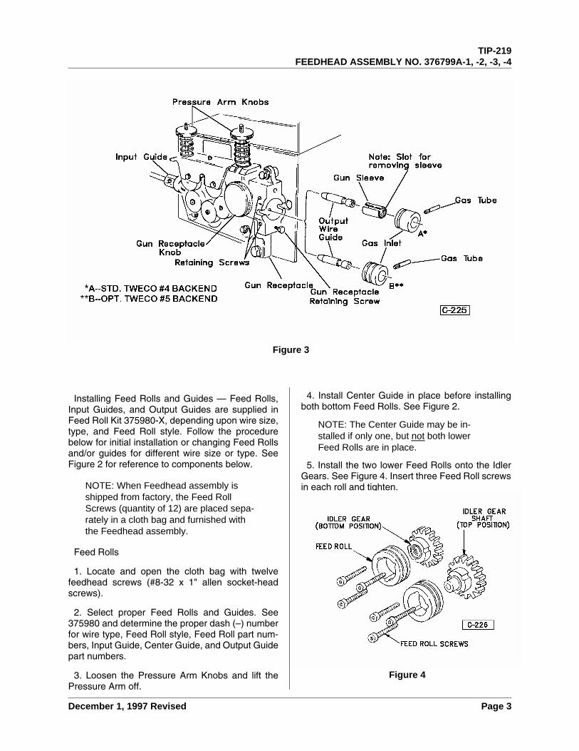
Installing Feed Rolls and Guides — Feed Rolls,Input Guides, and Output Guides are supplied inFeed Roll Kit 375980-X, depending upon wire size,type, and Feed Roll style. Follow the procedurebelow for initial installation or changing Feed Rollsand/or guides for different wire size or type. SeeFigure 2 for reference to components below.
NOTE: When Feedhead assembly isshipped from factory, the Feed RollScrews (quantity of 12) are placed sepa-rately in a cloth bag and furnished withthe Feedhead assembly.
Feed Rolls
1. Locate and open the cloth bag with twelvefeedhead screws (#8-32 x 1" allen socket-headscrews).
2. Select proper Feed Rolls and Guides. See375980 and determine the proper dash (–) numberfor wire type, Feed Roll style, Feed Roll part num-bers, Input Guide, Center Guide, and Output Guidepart numbers.
3. Loosen the Pressure Arm Knobs and lift thePressure Arm off.
4. Install Center Guide in place before installingboth bottom Feed Rolls. See Figure 2.
NOTE: The Center Guide may be in-stalled if only one, but not both lowerFeed Rolls are in place.
5. Install the two lower Feed Rolls onto the IdlerGears. See Figure 4. Insert three Feed Roll screwsin each roll and tighten.
Figure 3
Figure 4
TIP-219FEEDHEAD ASSEMBLY NO. 376799A-1, -2, -3, -4
December 1, 1997 Revised Page 3

NOTE: An Allen wrench is supplied fortightening the Feed Roll Screws. It is“stored” in a nylon retainer, located onthe rear end of the Feedhead Cover. SeeFigure 6.
6. To install the upper two Feed Rolls, follow theprocedure below:
a. Remove shaft screws which secure theIdler Gear/Shaft in place in the pressure arm.See Figure 5.
b. Install the Feed Rolls onto the Idler Gears,and secure in place with the Feed RollScrews. See Figure 4.
NOTE: When installing a Style 4 FeedRoll, which is made up of two pieces, besure to place the narrow piece on thegear first. This makes the groove line upwith the Guides.
c. Reinstall the Idler Gears/Feed Rolls intothe Pressure Arm. Fasten in place with theShaft Screws. See Figure 5.
d. Reassemble Pressure Arm onto the Feed-head Assembly by dropping it into place (seeFigure 2) and adjusting the Pressure ArmKnobs for proper tension. Adjust CenterGuide so that clearance between Guide andthe first Feed Roll is approximately 1/32 inch(0.8 mm). Tighten Center Guide RetainingScrew.
Input Guides
1. Loosen the Input Guide Retaining Screw andpull the Input Guide Spring (Item 1, Figure 1) out ofthe hex nylon Input Guide.
2. Insert the steel or nylatron Input Guide into thehex nylon Input Guide.
NOTE: The hex nylon Input Guide is aholding device for the Input Guide Springand the Input Guide which is supplied inthe Feed Roll and Guides Kit (375980-*).
*The dash number denotes which FeedRolls and Guides are furnished.
3. Reinstall the Input Guide Spring, pushing itagainst the Input Guide, and tighten the RetainingScrew.
Output Guide — The Output Guide may be in-stalled with the Gun Sleeve and the Gas Inlet (allmodels) in place.
1. Loosen the Output Guide Retaining Screw (seeFigure 2), and turn it out far enough to allow theGuide to slide in or out.
2. Insert the Guide into the Feedhead with long-nosed pliers or a piece of welding wire. Push theGuide up to the Feed Rolls until it “bottoms out”inside the Feedhead and tighten the RetainingScrew.
3. Proceed to install the Gun and Cable Assemblyas detailed above under Installing Gun and CableAssembly.
OperationThe operation of this feedhead is a function of the
wire feeder assembly of which it becomes a part.See the Wire Feeder Manual for the 2000 Series fordetails which affect this operation.
MaintenanceCleaning — Periodically blow off the feedhead
assembly with clean, dry, compressed air of notmore than 25 psi (172 kPa) pressure. Use care tonot strike component parts of the feedhead with theair hose nozzle.
Cleaning Feed Rolls and Gears — Using a smallwire brush, clean the grooves on the feed rolls andgear teeth frequently. To clean the wire groove,loosen the Pressure Arm Knob and raise the Pres-sure Arm. Remove the wire from the feed rolls.Clean the gear teeth and check the screws whichhold the feed rolls on the gears.
Feedhead Maintenance — The only point of main-tenance in the feedhead assembly is the motorbrushes. To inspect and/or change the brushes, thefeedhead assembly must be removed from the Con-
Figure 5
TIP-219FEEDHEAD ASSEMBLY NO. 376799A-1, -2, -3, -4
Page 4 December 1, 1997 Revised
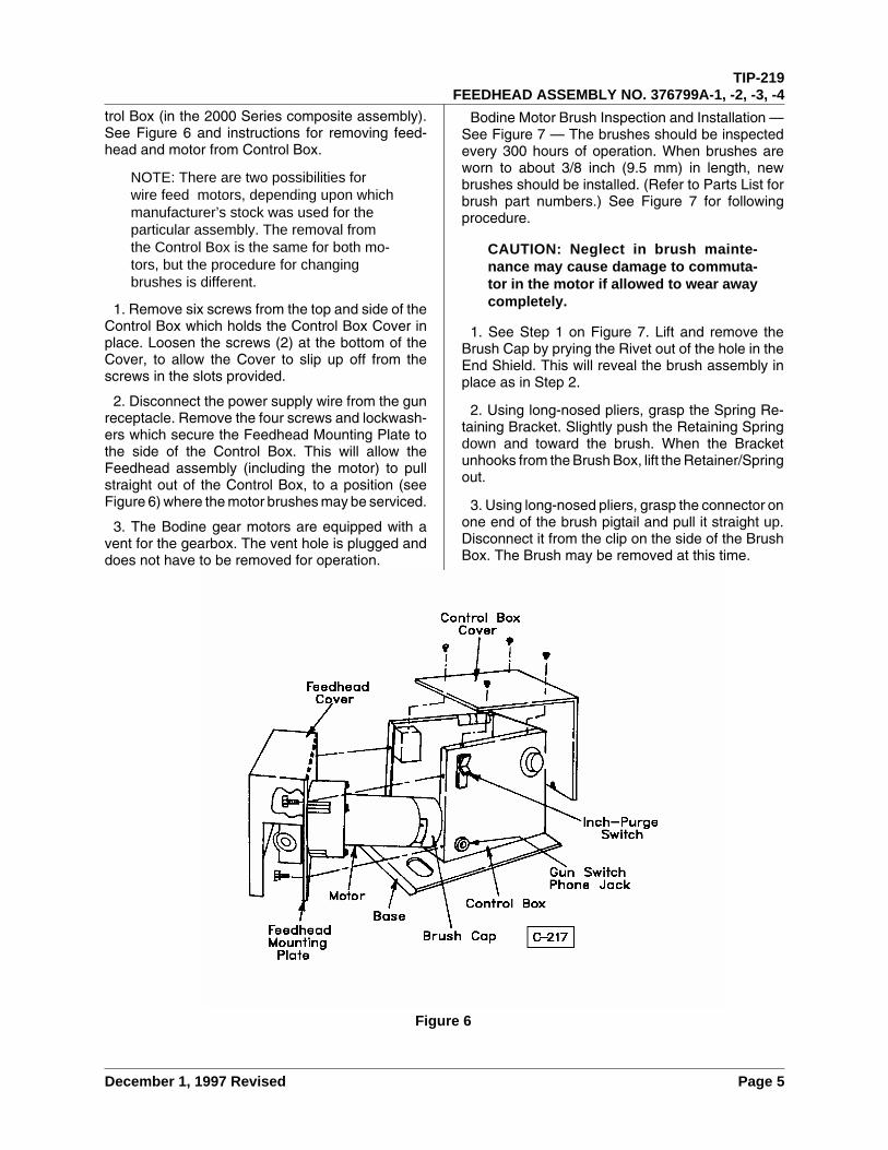
trol Box (in the 2000 Series composite assembly).See Figure 6 and instructions for removing feed-head and motor from Control Box.
NOTE: There are two possibilities forwire feed motors, depending upon whichmanufacturer’s stock was used for theparticular assembly. The removal fromthe Control Box is the same for both mo-tors, but the procedure for changingbrushes is different.
1. Remove six screws from the top and side of theControl Box which holds the Control Box Cover inplace. Loosen the screws (2) at the bottom of theCover, to allow the Cover to slip up off from thescrews in the slots provided.
2. Disconnect the power supply wire from the gunreceptacle. Remove the four screws and lockwash-ers which secure the Feedhead Mounting Plate tothe side of the Control Box. This will allow theFeedhead assembly (including the motor) to pullstraight out of the Control Box, to a position (seeFigure 6) where the motor brushes may be serviced.
3. The Bodine gear motors are equipped with avent for the gearbox. The vent hole is plugged anddoes not have to be removed for operation.
Bodine Motor Brush Inspection and Installation —See Figure 7 — The brushes should be inspectedevery 300 hours of operation. When brushes areworn to about 3/8 inch (9.5 mm) in length, newbrushes should be installed. (Refer to Parts List forbrush part numbers.) See Figure 7 for followingprocedure.
CAUTION: Neglect in brush mainte-nance may cause damage to commuta-tor in the motor if allowed to wear awaycompletely.
1. See Step 1 on Figure 7. Lift and remove theBrush Cap by prying the Rivet out of the hole in theEnd Shield. This will reveal the brush assembly inplace as in Step 2.
2. Using long-nosed pliers, grasp the Spring Re-taining Bracket. Slightly push the Retaining Springdown and toward the brush. When the Bracketunhooks from the Brush Box, lift the Retainer/Springout.
3. Using long-nosed pliers, grasp the connector onone end of the brush pigtail and pull it straight up.Disconnect it from the clip on the side of the BrushBox. The Brush may be removed at this time.
Figure 6
TIP-219FEEDHEAD ASSEMBLY NO. 376799A-1, -2, -3, -4
December 1, 1997 Revised Page 5
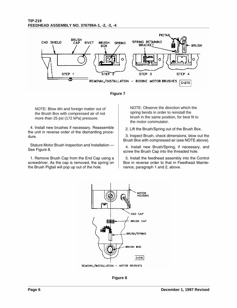
NOTE: Blow dirt and foreign matter out ofthe Brush Box with compressed air of notmore than 25 psi (172 kPa) pressure.
4. Install new brushes if necessary. Reassemblethe unit in reverse order of the dismantling proce-dure.
Stature Motor Brush Inspection and Installation —See Figure 8.
1. Remove Brush Cap from the End Cap using ascrewdriver. As the cap is removed, the spring onthe Brush Pigtail will pop up out of the hole.
NOTE: Observe the direction which thespring bends in order to reinstall thebrush in the same position, for best fit tothe motor commutator.
2. Lift the Brush/Spring out of the Brush Box.
3. Inspect Brush, check dimensions, blow out theBrush Box with compressed air (see NOTE above).
4. Install new Brush/Spring, if necessary, andscrew the Brush Cap into the threaded hole.
5. Install the feedhead assembly into the ControlBox in reverse order to that in Feedhead Mainte-nance, paragraph 1 and 2, above.
Figure 8
Figure 7
TIP-219FEEDHEAD ASSEMBLY NO. 376799A-1, -2, -3, -4
Page 6 December 1, 1997 Revised
PARTS LIST FOR ASSEMBLY NUMBERS 376799A-1,-2, -3, -4
Equipment IdentificationAll identification numbers as described in the In-
troduction chapter must be furnished when orderingparts or making inquiries. This information is usuallyfound on the nameplate attached to the equipment.Be sure to include any dash numbers following theSpecification or Assembly numbers.
How To Use This Parts ListThe Parts List is a combination of an illustration
(Figure Number) and a corresponding list of partswhich contains a breakdown of the equipment intoassemblies, subassemblies, and detail parts. Allparts of the equipment are listed except for commer-cially available hardware, bulk items such as wire,cable, sleeving, tubing, etc., and permanently at-tached items which are soldered, riveted, or welded
to another part. The part descriptions may be in-dented to show part relationships.
To determine the part number, description, quan-tity, or application of an item, simply locate the itemin question from the illustration and refer to that itemnumber in the corresponding Parts List.
An “Application Code” is used to distinguish partsthat are applicable only to certain Specificationsand/or Assemblies. This code is found in the right-most column of the Parts List. If an item in the PartsList applies to all Specifications or Assemblies, theword “ALL” will be in the Application Code column.Refer to the following list to determine the appropri-ate Application Codes for the Specifications or As-semblies covered by this manual. If only theassembly or specification number is listed, the useof an Application Code does not apply to this man-ual.
ASSEMBLY NUMBER APPLICATION CODE
376799A-1 A
376799A-2 B
376799A-3 C
376799A-4 D
MPL-224PARTS LIST FOR ASSEMBLY NUMBER 376799A-1, -2, -3, -4
May 29, 1996 Revised Page 1
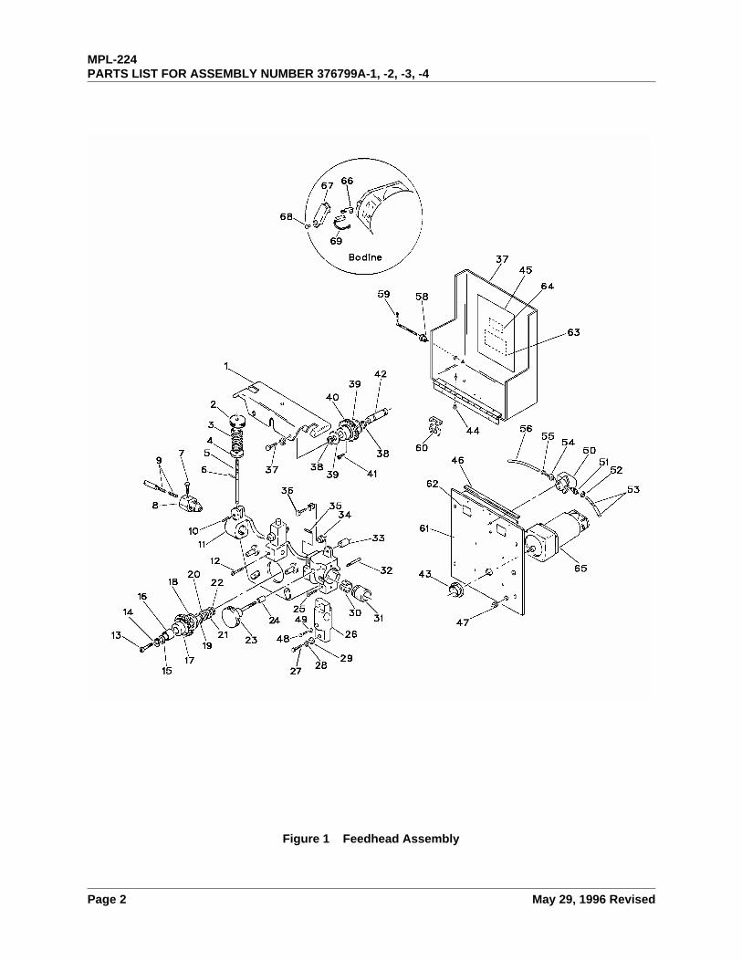
Figure 1 Feedhead Assembly
MPL-224PARTS LIST FOR ASSEMBLY NUMBER 376799A-1, -2, -3, -4
Page 2 May 29, 1996 Revised
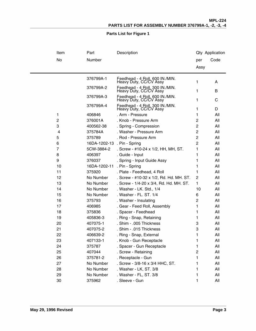
376799A-1 Feedhead - 4 Roll, 600 IN./MIN.Heavy Duty, CC/CV Assy 1 A
376799A-2 Feedhead - 4 Roll, 300 IN./MIN.Heavy Duty, CC/CV Assy 1 B
376799A-3 Feedhead - 4 Roll, 600 IN./MIN.Heavy Duty, CC/CV Assy 1 C
376799A-4 Feedhead - 4 Roll, 300 IN./MIN.Heavy Duty, CC/CV Assy 1 D
1 406846 . Arm - Pressure 1 All2 376001A . Knob - Pressure Arm 2 All3 400562-38 . Spring - Compression 2 All4 375784A . Washer - Pressure Arm 2 All
5 375789 . Rod - Pressure Arm 2 All6 16DA-1202-13 . Pin - Spring 2 All7 5CW-3884-2 . Screw - #10-24 x 1/2, HH, MH, ST. 1 All8 406397 . Guide - Input 1 All9 376037 . Spring - Input Guide Assy 1 All10 16DA-1202-11 . Pin - Spring 1 All11 375920 . Plate - Feedhead, 4 Roll 1 All12 No Number . Screw - #10-32 x 1/2, Rd. Hd. MH. ST. 2 All13 No Number . Screw - 1/4-20 x 3/4, Rd. Hd. MH. ST. 1 All14 No Number . Washer - LK. Std., 1/4 10 All15 No Number . Washer - FL. ST. 1/4 6 All16 375793 . Washer - Insulating 2 All17 406985 . Gear - Feed Roll, Assembly 1 All18 375836 . Spacer - Feedhead 1 All19 405836-3 . Ring - Snap, Retaining 1 All20 407075-1 . Shim - .005 Thickness 3 All21 407075-2 . Shim - .015 Thickness 3 All22 406639-2 . Ring - Snap, External 1 All23 407133-1 . Knob - Gun Receptacle 1 All24 375787 . Spacer - Gun Receptacle 1 All25 407044 . Screw - Retaining 2 All26 375781-2 . Receptacle - Gun 1 All27 No Number . Screw - 3/8-16 x 3/4 HHC, ST. 1 All28 No Number . Washer - LK, ST. 3/8 1 All29 No Number . Washer - FL, ST. 3/8 1 All30 375962 . Sleeve - Gun 1 All
Item Part Description Qty Application
No Number per Code
Assy
Parts List for Figure 1
MPL-224PARTS LIST FOR ASSEMBLY NUMBER 376799A-1, -2, -3, -4
May 29, 1996 Revised Page 3
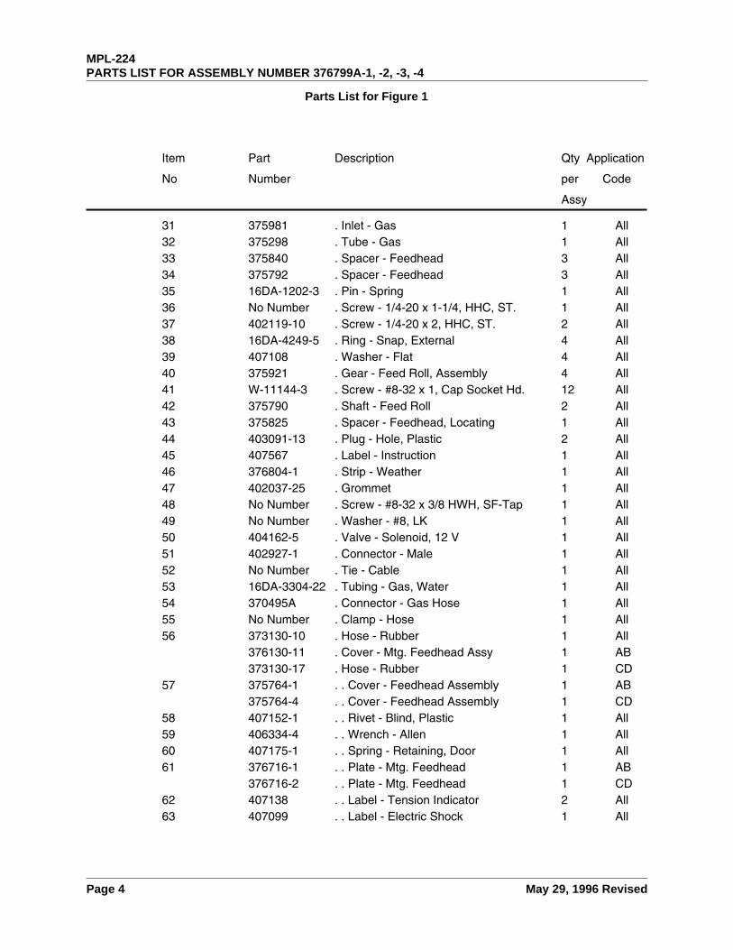
31 375981 . Inlet - Gas 1 All32 375298 . Tube - Gas 1 All33 375840 . Spacer - Feedhead 3 All34 375792 . Spacer - Feedhead 3 All35 16DA-1202-3 . Pin - Spring 1 All36 No Number . Screw - 1/4-20 x 1-1/4, HHC, ST. 1 All37 402119-10 . Screw - 1/4-20 x 2, HHC, ST. 2 All38 16DA-4249-5 . Ring - Snap, External 4 All39 407108 . Washer - Flat 4 All40 375921 . Gear - Feed Roll, Assembly 4 All41 W-11144-3 . Screw - #8-32 x 1, Cap Socket Hd. 12 All42 375790 . Shaft - Feed Roll 2 All43 375825 . Spacer - Feedhead, Locating 1 All44 403091-13 . Plug - Hole, Plastic 2 All45 407567 . Label - Instruction 1 All46 376804-1 . Strip - Weather 1 All47 402037-25 . Grommet 1 All48 No Number . Screw - #8-32 x 3/8 HWH, SF-Tap 1 All49 No Number . Washer - #8, LK 1 All50 404162-5 . Valve - Solenoid, 12 V 1 All51 402927-1 . Connector - Male 1 All52 No Number . Tie - Cable 1 All53 16DA-3304-22 . Tubing - Gas, Water 1 All54 370495A . Connector - Gas Hose 1 All55 No Number . Clamp - Hose 1 All56 373130-10 . Hose - Rubber 1 All
376130-11 . Cover - Mtg. Feedhead Assy 1 AB373130-17 . Hose - Rubber 1 CD
57 375764-1 . . Cover - Feedhead Assembly 1 AB375764-4 . . Cover - Feedhead Assembly 1 CD
58 407152-1 . . Rivet - Blind, Plastic 1 All59 406334-4 . . Wrench - Allen 1 All60 407175-1 . . Spring - Retaining, Door 1 All61 376716-1 . . Plate - Mtg. Feedhead 1 AB
376716-2 . . Plate - Mtg. Feedhead 1 CD62 407138 . . Label - Tension Indicator 2 All63 407099 . . Label - Electric Shock 1 All
Item Part Description Qty Application
No Number per Code
Assy
Parts List for Figure 1
MPL-224PARTS LIST FOR ASSEMBLY NUMBER 376799A-1, -2, -3, -4
Page 4 May 29, 1996 Revised

64 406636 . . Label 1 All65 376721-1 . Motor - Gear, Feedhead Assy 1 A
376721-2 . Motor - Gear, Feedhead Assy 1 B
66 407192 Spring - Brush 267 407086 Cap - Brush 268 407193 Rivet 269 407089 Brush 2
Item Part Description Qty Application
No Number per Code
Assy
Parts List for Figure 1
MPL-224PARTS LIST FOR ASSEMBLY NUMBER 376799A-1, -2, -3, -4
May 29, 1996 Revised Page 5

This page intentionally left blank.
MPL-224PARTS LIST FOR ASSEMBLY NUMBER 376799A-1, -2, -3, -4
Page 6 May 29, 1996 Revised
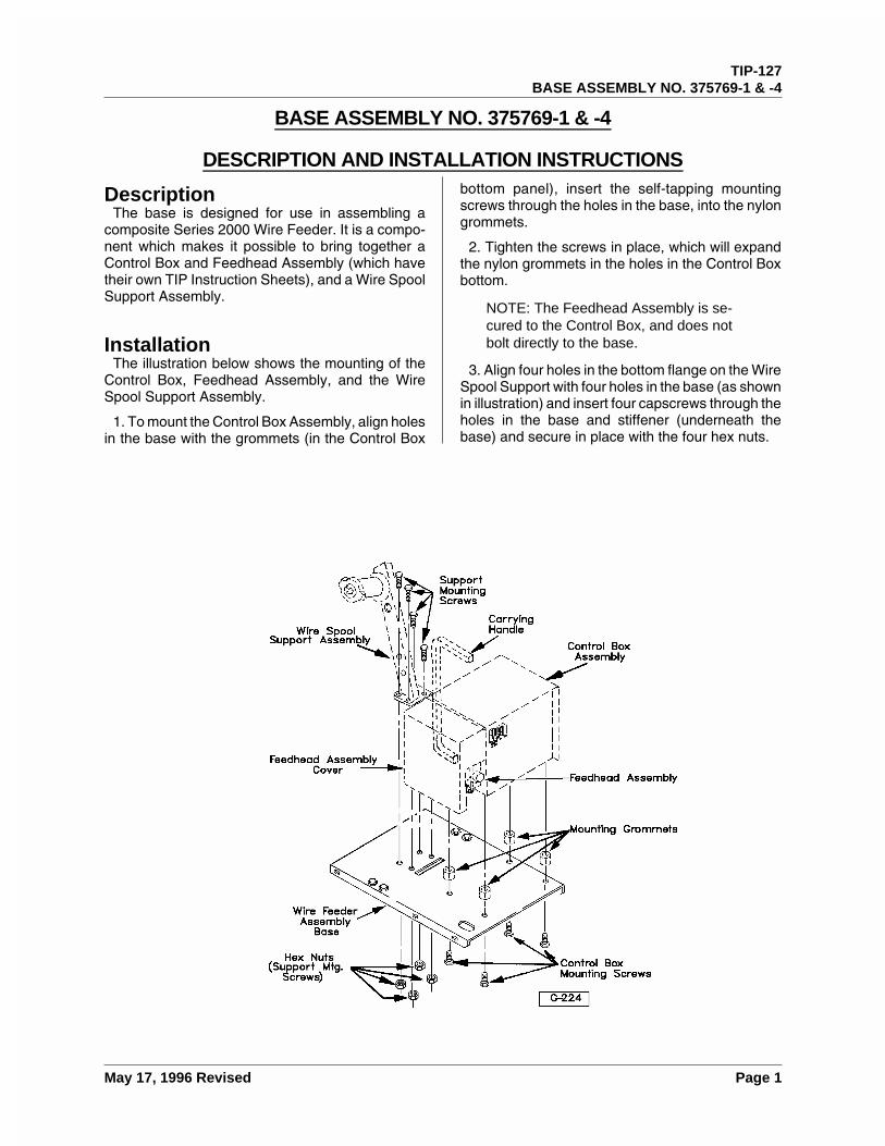
BASE ASSEMBLY NO. 375769-1 & -4
DESCRIPTION AND INSTALLATION INSTRUCTIONS
DescriptionThe base is designed for use in assembling a
composite Series 2000 Wire Feeder. It is a compo-nent which makes it possible to bring together aControl Box and Feedhead Assembly (which havetheir own TIP Instruction Sheets), and a Wire SpoolSupport Assembly.
InstallationThe illustration below shows the mounting of the
Control Box, Feedhead Assembly, and the WireSpool Support Assembly.
1. To mount the Control Box Assembly, align holesin the base with the grommets (in the Control Box
bottom panel), insert the self-tapping mountingscrews through the holes in the base, into the nylongrommets.
2. Tighten the screws in place, which will expandthe nylon grommets in the holes in the Control Boxbottom.
NOTE: The Feedhead Assembly is se-cured to the Control Box, and does notbolt directly to the base.
3. Align four holes in the bottom flange on the WireSpool Support with four holes in the base (as shownin illustration) and insert four capscrews through theholes in the base and stiffener (underneath thebase) and secure in place with the four hex nuts.
TIP-127BASE ASSEMBLY NO. 375769-1 & -4
May 17, 1996 Revised Page 1

This page intentionally left blank.
TIP-127BASE ASSEMBLY NO. 375769-1 & -4
Page 2 May 17, 1996 Revised
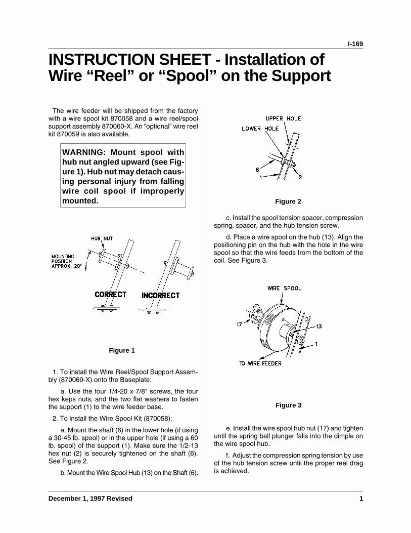
INSTRUCTION SHEET - Installation ofWire “Reel” or “Spool” on the Support
The wire feeder will be shipped from the factorywith a wire spool kit 870058 and a wire reel/spoolsupport assembly 870060-X. An “optional” wire reelkit 870059 is also available.
WARNING: Mount spool withhub nut angled upward (see Fig-ure 1). Hub nut may detach caus-ing personal injury from fallingwire coil spool if improperlymounted.
1. To install the Wire Reel/Spool Support Assem-bly (870060-X) onto the Baseplate:
a. Use the four 1/4-20 x 7/8" screws, the fourhex keps nuts, and the two flat washers to fastenthe support (1) to the wire feeder base.
2. To install the Wire Spool Kit (870058):
a. Mount the shaft (6) in the lower hole (if usinga 30-45 lb. spool) or in the upper hole (if using a 60lb. spool) of the support (1). Make sure the 1/2-13hex nut (2) is securely tightened on the shaft (6).See Figure 2.
b. Mount the Wire Spool Hub (13) on the Shaft (6).
c. Install the spool tension spacer, compressionspring, spacer, and the hub tension screw.
d. Place a wire spool on the hub (13). Align thepositioning pin on the hub with the hole in the wirespool so that the wire feeds from the bottom of thecoil. See Figure 3.
e. Install the wire spool hub nut (17) and tightenuntil the spring ball plunger falls into the dimple onthe wire spool hub.
f. Adjust the compression spring tension by useof the hub tension screw until the proper reel dragis achieved.
Figure 1
Figure 2
Figure 3
I-169
December 1, 1997 Revised 1

3. To install the Wire Reel Kit (870059):
a. Mount the shaft (6) in the upper hole of thesupport (1) to assure proper clearance for the wirereel (7). See Figure 4.
b. Mount the wire reel (7) on the shaft (6).
c. Install the wire reel washer, the steel wire reelwasher, compression spring, “T” wire reel washer,and the drag adjusting screw.
d. Loosen the wing nuts holding the movablearms. Rotate the arms inward towards the center ofthe reel (7). Place the coiled wire on the reel so thewire feeds from the bottom of the coil to the wirefeeder. See Figure 5.
e. Reposition the movable arms outward andtighten the wing nuts.
f. Tighten the drag adjusting screw until thedesired reel drag is achieved.
Figure 4 Figure 5
I-169
2 December 1, 1997 Revised
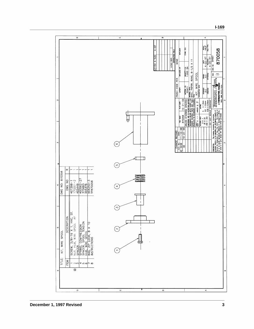
I-169
December 1, 1997 Revised 3

This page intentionally left blank.
I-169
4 December 1, 1997 Revised
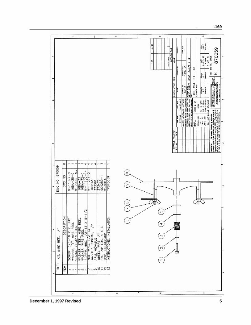
I-169
December 1, 1997 Revised 5

This page intentionally left blank.
I-169
6 December 1, 1997 Revised
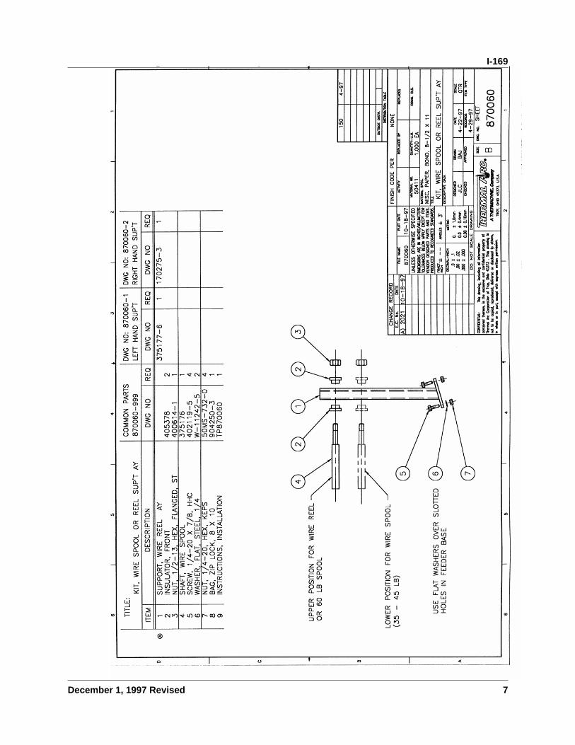
I-169
December 1, 1997 Revised 7

This page intentionally left blank.
I-169
8 December 1, 1997 Revised
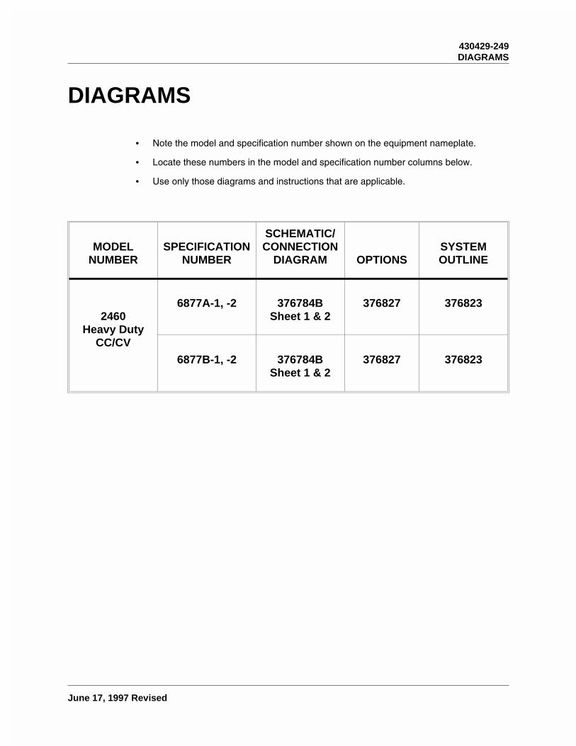
DIAGRAMS
• Note the model and specification number shown on the equipment nameplate.
• Locate these numbers in the model and specification number columns below.
• Use only those diagrams and instructions that are applicable.
MODELNUMBER
SPECIFICATIONNUMBER
SCHEMATIC/CONNECTION
DIAGRAM OPTIONSSYSTEMOUTLINE
2460Heavy Duty
CC/CV
6877A-1, -2 376784BSheet 1 & 2
376827 376823
6877B-1, -2 376784BSheet 1 & 2
376827 376823
430429-249DIAGRAMS
June 17, 1997 Revised
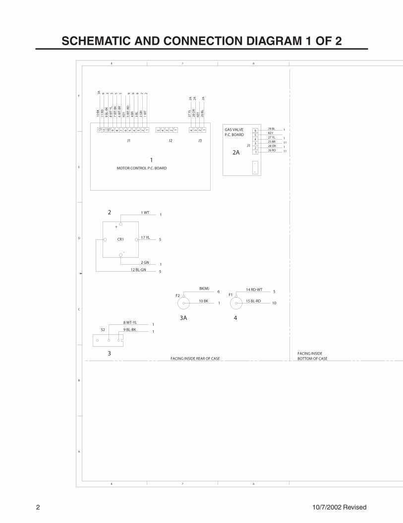
2 10/7/2002 Revised
SCHEMATIC AND CONNECTION DIAGRAM 1 OF 2
1
2
3
2A
3A 4
J2J1 J3
29 B
L2A
12K
EY34
28 O
R27
YL
2A 2A
5 4 3 2 159
5 W
T-RD
994
BR
3 B
L4 3
22
GN
2 12
1 W
T
KEY
76
WT-
BR
589
7 W
T-B
K8
WT-
YL
3 5
9 B
L-B
K3
6
3A10
BK
611
RD
11
MOTOR CONTROL P.C. BOARD
+
CR1
-
1 WT 1
17 YL 5
2 GN 112 BL-GN 5
9 BL-BK 1
8 WT-YL 1S2
GAS VALVEP.C. BOARD 5
11127 YL
25 BR43
28 OR21 1126 RD
6KEY29 BL 1
1
BK(M)
10 BK 1
14 RD-WT
15 BL-RD 10
F2 F16 5
-
-
12 10
A
B
D
C
6
F
E
78
78 6
J1
FACING INSIDE REAR OF CASEFACING INSIDEBOTTOM OF CASE

10/7/2002 Revised 3
PAGES AFFECTEDDATE
REVISION CHARTECN NO.REV
DIAGRAM, CONNECTION & SCHEMATIC
2460 HEAVY DUTY WIRE FEEDER
NONE
1 OF 2
FULLTLT JLC 7-29-91
376784B 10-7-02
TLT TLT 8-15-91
150 8-91
TECH PUB
376784B
59
810
11
6
7
8 7 6 5 4 3 2 1
4 BK12 BL-GN14 RD-WT
21 OR-WT7 WT-BK23 WT-GN
782148
3 BL
4 BR
5 WT-RD1
1
1
R14 BK
5
TO WORK
23 WT-GN5
21 OR-WT5
J4
15 BL-RD 41116 BR-BK
S1
16 BR-BK 10
FEEDHEAD
2A
2A
B1
L1
26 RD
25 BR
11 RD1
TB1
BK
RD
(M)3A
A) PP1192 8-14-96
6 WT-BR1 17 YL 2
13 YL-BK
18 BK-BL
22 RD-BL
20 BK-OR
CHANGE RECORDE.C. No. DATE
PLOT DATE
CHECKED APPROVED RECORDS ITEM TYPE
DESIGNED DRAWN DATE SCALE
COMM. CLS.
DESCRIPTIVE DATA
TITLE
MATERIAL SPEC.
MATERIAL NO.
ACTIVITY
FINISH CODE PER
REPLACED BY REPLACES
QUANTITY-U.M.
DWG. NO.SIZE
C
FRACT.INCH ±
SHEET
FILE NAME
1235 4
DISTRIBUTION TABLE
OUTSIDE DISTR.
A
B
C
D
E
F
5 4 3 2 1
CONFIDENTIAL: This drawing, including all information contained thereon, is the exclusive and confidential property of Thermal Arc Corporation of Troy, Ohio 45373 . This drawing isnot to be copied, reproduced, delivered or disclosed to others,in whole or in part, except with express written permission. TROY, OHIO 45373, U.S.A.
ANGLES ± 3˚
UNLESS OTHERWISE SPECIFIEDDIMENSIONS ARE IN INCHES/MILLIMETERSTOLERANCES BELOW APPLY EXCEPT FORVENDOR DESIGNED PARTS AND ITEMS.PRODUCED TO RECOGNIZED STANDARDS.
DECIMAL-INCH
0.00 ± 0.1mm
0.0 ± 0.4mm
0. ± 1.0mm
.000 ± .003
.00 ± .02
DO NOT SCALE DRAWING
.0 ± .1
A THERMADYNE CompanyR
R
FACING INSIDE FRONT OF CASE
6-6-971472B 1, 2
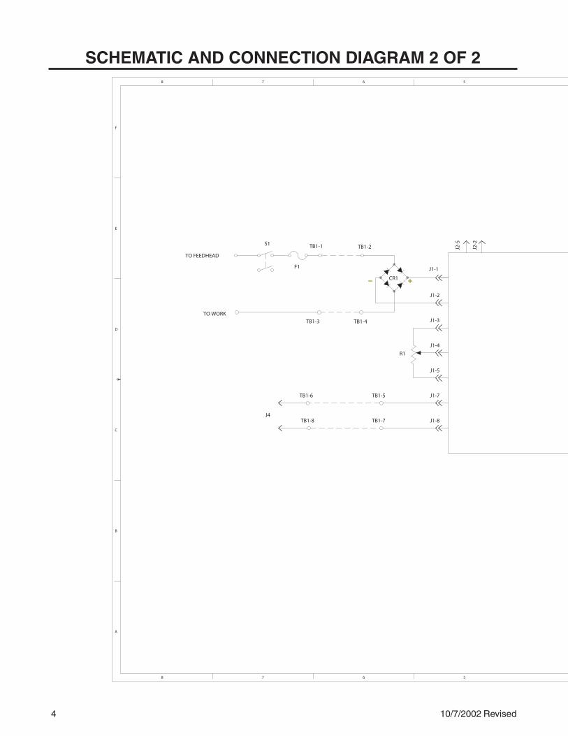
4 10/7/2002 Revised
SCHEMATIC AND CONNECTION DIAGRAM 2 OF 2
TO FEEDHEAD
S1
TO WORK
J1-1
J1-2
J1-3
J1-4
J1-5
J1-7
J1-8
TB1-6
TB1-8
R1
CR1
J2-2
J2-5
TB1-5
TB1-7
TB1-2
TB1-3 TB1-4
TB1-1
F1
J4
A
B
D
C
6 5
F
E
78
78 56
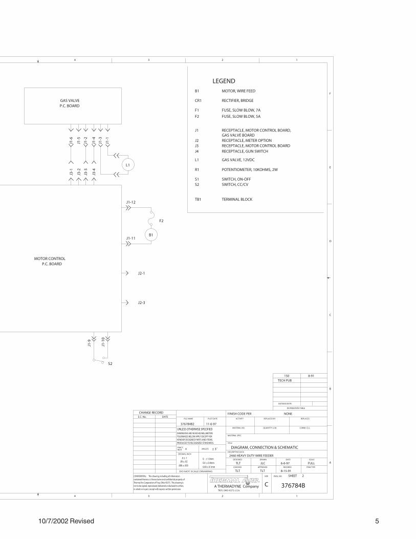
10/7/2002 Revised 5
LEGEND
L1
J1-6
B1
S2
J3-1
J1-1
GAS VALVEP.C. BOARD
B1
CR1
F1
F2
J1
J2J3
R1
S1
J4
S2
TB1
L1 GAS VALVE, 12VDC
TERMINAL BLOCK
SWITCH, CC/CV
RECEPTACLE, GUN SWITCH
SWITCH, ON-OFF
POTENTIOMETER, 10KOHMS, 2W
RECEPTACLE, MOTOR CONTROL BOARDRECEPTACLE, METER OPTION
RECEPTACLE, MOTOR CONTROL BOARD,
FUSE, SLOW BLOW, 5A
FUSE, SLOW BLOW, 7A
RECTIFIER, BRIDGE
MOTOR, WIRE FEEDJ1
-9
J1-1
0
J1-12
J1-11
J2-1
J2-3
F2
MOTOR CONTROL P.C. BOARD
J1-3
J3-2
J1-5
J3-3
J1-2
J3-4
J1-4
GAS VALVE BOARD
DIAGRAM, CONNECTION & SCHEMATIC
2460 HEAVY DUTY WIRE FEEDER
NONE
2
FULLTLT JLC 6-6-97
376784B2 11-6-97
TLT TLT 8-15-91
150 8-91
TECH PUB
376784B
CHANGE RECORDE.C. No. DATE
PLOT DATE
CHECKED APPROVED RECORDS ITEM TYPE
DESIGNED DRAWN DATE SCALE
COMM. CLS.
DESCRIPTIVE DATA
TITLE
MATERIAL SPEC.
MATERIAL NO.
ACTIVITY
FINISH CODE PER
REPLACED BY REPLACES
QUANTITY-U.M.
DWG. NO.SIZE
C
FRACT.INCH ±
SHEET
FILE NAME
1234
DISTRIBUTION TABLE
OUTSIDE DISTR.
A
B
C
D
E
F
4 3 2 1
CONFIDENTIAL: This drawing, including all information contained thereon, is the exclusive and confidential property of Thermal Arc Corporation of Troy, Ohio 45373 . This drawing isnot to be copied, reproduced, delivered or disclosed to others,in whole or in part, except with express written permission. TROY, OHIO 45373, U.S.A.
ANGLES ± 3˚
UNLESS OTHERWISE SPECIFIEDDIMENSIONS ARE IN INCHES/MILLIMETERSTOLERANCES BELOW APPLY EXCEPT FORVENDOR DESIGNED PARTS AND ITEMS.PRODUCED TO RECOGNIZED STANDARDS.
DECIMAL-INCH
0.00 ± 0.1mm
0.0 ± 0.4mm
0. ± 1.0mm
.000 ± .003
.00 ± .02
DO NOT SCALE DRAWING
.0 ± .1
A THERMADYNE CompanyR
R

April 14, 2005 Revised
LIMITED WARRANTY
LIMITED WARRANTY: Thermal Arc®, Inc., A Thermadyne Company, hereafter, “Thermal Arc” warrants to customers of itsauthorized distributors hereafter “Purchaser” that its products will be free of defects in workmanship or material. Should anyfailure to conform to this warranty appear within the time period applicable to the Thermal Arc products as stated below, ThermalArc shall, upon notification thereof and substantiation that the product has been stored, installed, operated, and maintained inaccordance with Thermal Arc’s specifications, instructions, recommendations and recognized standard industry practice, and notsubject to misuse, repair, neglect, alteration, or accident, correct such defects by suitable repair or replacement, at Thermal Arc’ssole option, of any components or parts of the product determined by Thermal Arc to be defective.
THERMAL ARC MAKES NO OTHER WARRANTY, EXPRESS OR IMPLIED. THIS WARRANTY IS EXCLUSIVE AND IN LIEU OFALL OTHERS, INCLUDING, BUT NOT LIMITED TO ANY WARRANTY OF MERCHANTABILITY OR FITNESS FOR ANYPARTICULAR PURPOSE.
LIMITATION OF LIABILITY: THERMALARC SHALL NOT UNDER ANY CIRCUMSTANCES BE LIABLE FOR SPECIAL, INDIRECTOR CONSEQUENTIAL DAMAGES, SUCH AS, BUT NOT LIMITED TO, LOST PROFITS AND BUSINESS INTERRUPTION. Theremedies of the Purchaser set forth herein are exclusive and the liability of Thermal Arc with respect to any contract, or anythingdone in connection therewith such as the performance or breach thereof, or from the manufacture, sale, delivery, resale, or use ofany goods covered by or furnished by Thermal Arc whether arising out of contract, negligence, strict tort, or under any warranty, orotherwise, shall not, except as expressly provided herein, exceed the price of the goods upon which such liability is based. Noemployee, agent, or representative of Thermal Arc is authorized to change this warranty in any way or grant any other warranty.
PURCHASER’S RIGHTS UNDER THIS WARRANTY ARE VOID IF REPLACEMENT PARTS OR ACCESSORIES ARE USED WHICHIN THERMALARC’S SOLE JUDGEMENT MAY IMPAIR THE SAFETY OR PERFORMANCE OF ANY THERMALARC PRODUCT.PURCHASER’S RIGHTS UNDER THIS WARRANTY ARE VOID IF THE PRODUCT IS SOLD TO PURCHASER BY NON-AUTHORIZED PERSONS.
POWER SUPPLIES ALL OTHER LABOR POWER SUPPLIES MAIN POWER MAGNETICS (STATIC & ROTATING) 3 YEARS 3 YEAR ORIGINAL MAIN POWER RECTIFIER 3 YEARS 3 YEAR CONTROL PC BOARD 3 YEARS 3 YEAR ALL OTHER CIRCUITS AND COMPONENTS INCLUDING BUT 1 YEAR 1 YEAR NOT LIMITED TO: CONTACTORS, RELAYS, SOLENOIDS, PUMPS, POWER SWITCHING SEMI-CONDUCTORS ENGINES: ENGINES ARE NOT WARRANTED BY THERMAL ARC, ALTHOUGH MOST ARE WARRANTED BY THE ENGINE MANUFACTURER, SEE THE ENGINE MANUFACTURES WARRANTY FOR DETAILS. CONSOLES, CONTROL EQUIPMENT, HEAT EXCHANGES, 1 YEAR 1 YEAR
AND ACCESSORY EQUIPMENT TORCH AND LEADS 180 DAYS 180 DAYS REPAIR/REPLACEMENT PARTS 90 DAYS 90 DAYS
The warranty is effective for the time stated below beginning on the date that the authorized distributor delivers the products to thePurchaser. Notwithstanding the foregoing, in no event shall the warranty period extend more than the time stated plus one yearfrom the date Thermal Arc delivered the product to the authorized distributor.
NOTE: Dragster 85® excluded from this policy. Refer to Dragster 85 warranty in Dragster 85 Owner’s Manual.
Warranty repairs or replacement claims under this limited warranty must be submitted to Thermal Arc by an authorized ThermalArc repair facility within thirty (30) days of purchaser’s notice of any Warranty Claim. No transportation costs of any kind will bepaid under this warranty. Transportation charges to send products to an authorized warranty repair facility shall be the responsibilityof the Purchaser. All returned goods shall be at the Purchaser’s risk and expense. This warranty supersedes all previous ThermalArc warranties. Thermal Arc® is a Registered Trademark of Thermadyne Industries Inc.
September 27, 2004