424521 /2018 Pages 65-68 Fluid & Particulate Systems Fluid...
34
Fluid & Particulate Systems 424521 / 2010 Fluid & Particulate Systems ÅA 424521 / 2018 Fluid and Particulate systems 424521 /2018 DYNAMIC FLOWS / COMPRESSIBLE FLOWS / MOMENTUM BALANCES Ron Zevenhoven ÅA Thermal and Flow Engineering [email protected] 4 Pages 65-68 added 3.4.2018 Fluid & Particulate Systems 424521 / 2010 Fluid & Particulate Systems ÅA 424521 / 2018 4.1 Dynamic, time-dependent flow Åbo Akademi University - Värme- och Strömningsteknik Biskopsgatan 8, FI-20500 Åbo / Turku Finland RoNz 2 april 2018
Transcript of 424521 /2018 Pages 65-68 Fluid & Particulate Systems Fluid...

Flu
id &
Par
ticul
ate
Sys
tem
s42
4521
/ 2
010
Flui
d &
Par
ticul
ate
Syst
ems
ÅA
424
521
/ 2
018
Fluid and Particulate systems 424521 /2018
DYNAMIC FLOWS /COMPRESSIBLE FLOWS /MOMENTUM BALANCES
Ron ZevenhovenÅA Thermal and Flow Engineering
4
Pages 65-68added 3.4.2018
Flu
id &
Par
ticul
ate
Sys
tem
s42
4521
/ 2
010
Flui
d &
Par
ticul
ate
Syst
ems
ÅA
424
521
/ 2
018
4.1 Dynamic, time-dependentflow
Åbo Akademi University - Värme- och Strömningsteknik Biskopsgatan 8, FI-20500 Åbo / Turku Finland
RoNz 2april 2018

Flu
id &
Par
ticul
ate
Sys
tem
s42
4521
/ 2
010
Flui
d &
Par
ticul
ate
Syst
ems
ÅA
424
521
/ 2
018
Dynamic Flow
t
Flu
id &
Par
ticul
ate
Sys
tem
s42
4521
/ 2
010
Flui
d &
Par
ticul
ate
Syst
ems
ÅA
424
521
/ 2
018
Two processes
tseconds minutes
Fastprocess
Slowprocess
april 2018 RoNz 4Åbo Akademi University - Värme- och Strömningsteknik Biskopsgatan 8, FI-20500 Åbo / Turku Finland

Flu
id &
Par
ticul
ate
Sys
tem
s42
4521
/ 2
010
Flui
d &
Par
ticul
ate
Syst
ems
ÅA
424
521
/ 2
018
Slow process
minutes
Fastprocess
Slowprocess
seconds
Calculate the pseudo-stationary state at several points during the process.Integrate the result to achieve the value of the searched variable.
4.1
Lowering of level in storage vessel;Lowers tube inlet pressure
2
1 )()(:Xproperty of change 12
X
X Xf
dxttXf
dt
dX
april 2018 RoNz 5Åbo Akademi University - Värme- och Strömningsteknik Biskopsgatan 8, FI-20500 Åbo / Turku Finland
Flu
id &
Par
ticul
ate
Sys
tem
s42
4521
/ 2
010
Flui
d &
Par
ticul
ate
Syst
ems
ÅA
424
521
/ 2
018
Fast process
minutes
Fastprocess
Slowprocess
seconds
The state is changing within the control volume; time derivates of energyneed to be accounted for.
Acceleration of the water mass in the of tube: F = mꞏa = Δp/L
april 2018 RoNz 6Åbo Akademi University - Värme- och Strömningsteknik Biskopsgatan 8, FI-20500 Åbo / Turku Finland
Flu
id &
Par
ticul
ate
Sys
tem
s42
4521
/ 2
010
Flui
d &
Par
ticul
ate
Syst
ems
ÅA
424
521
/ 2
018
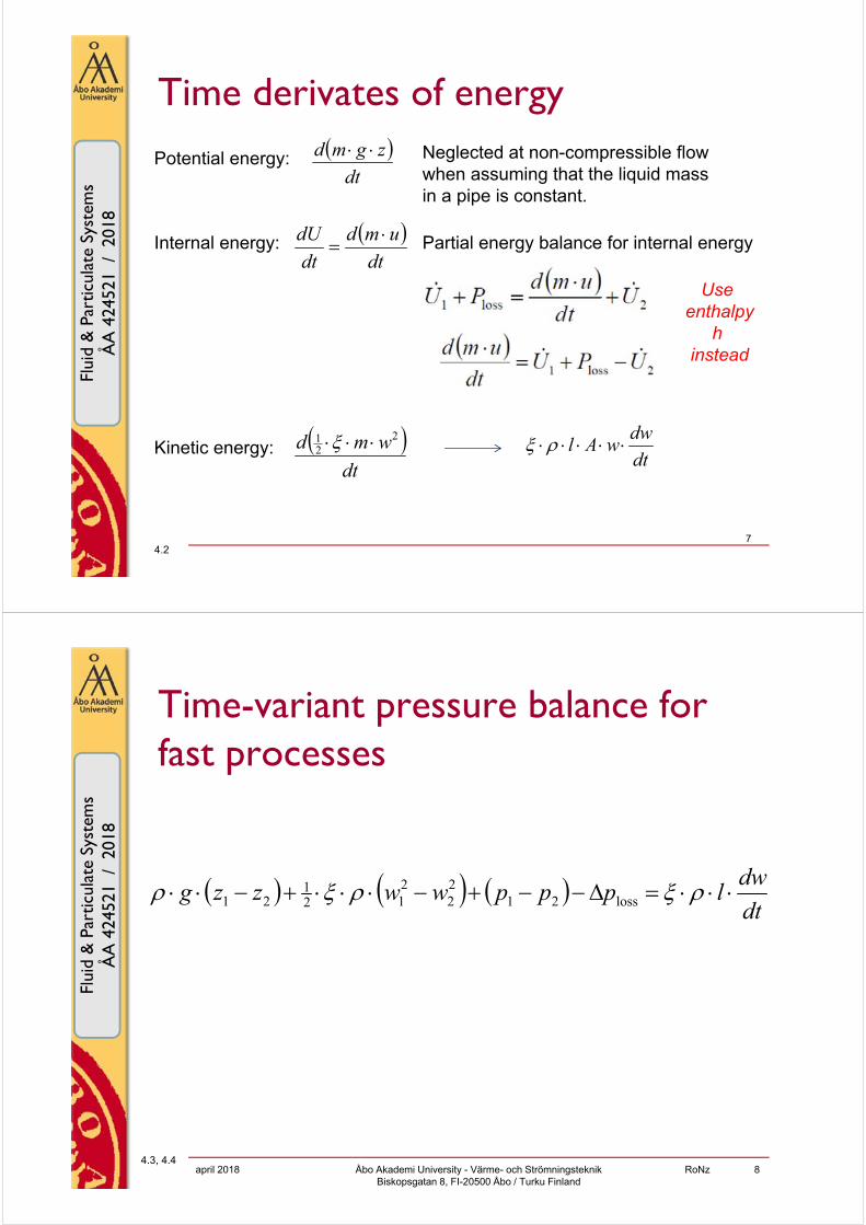
Time derivates of energy dt
zgmd
dt
umd
dt
dU
dt
wmd 221
Potential energy:
Internal energy:
Kinetic energy:
Neglected at non-compressible flowwhen assuming that the liquid massin a pipe is constant.
Partial energy balance for internal energy
dt
dwwAl
4.27
Useenthalpy
hinstead
Flu
id &
Par
ticul
ate
Sys
tem
s42
4521
/ 2
010
Flui
d &
Par
ticul
ate
Syst
ems
ÅA
424
521
/ 2
018
Time-variant pressure balance for fast processes
dt
dwlpppwwzzg loss21
22
212
121
4.3, 4.4april 2018 RoNz 8Åbo Akademi University - Värme- och Strömningsteknik
Biskopsgatan 8, FI-20500 Åbo / Turku Finland

Flu
id &
Par
ticul
ate
Sys
tem
s42
4521
/ 2
010
Flui
d &
Par
ticul
ate
Syst
ems
ÅA
424
521
/ 2
018
4.2 Example: water hammer
Åbo Akademi University - Värme- och Strömningsteknik Biskopsgatan 8, FI-20500 Åbo / Turku Finland
RoNz 9april 2018
Flu
id &
Par
ticul
ate
Sys
tem
s42
4521
/ 2
010
Flui
d &
Par
ticul
ate
Syst
ems
ÅA
424
521
/ 2
018
Water hammer
What happens if the valve is suddenly closed?
Theoretically: Deceleration of an incompressible fluid and a non-expandablepipe would cause infinite high pressure before the valve.
Practically: The kinetic energy of the liquid in motion will compress the fluid andexpand the pipe (a slightly bigger perimeter). This results in a high pressureshock wave bouncing back and forth, which is experienced as a loud bangresembling a hammering noise. Friction will, however, decay the wave fast.
l
april 2018 RoNz 10Åbo Akademi University - Värme- och Strömningsteknik Biskopsgatan 8, FI-20500 Åbo / Turku Finland

Flu
id &
Par
ticul
ate
Sys
tem
s42
4521
/ 2
010
Flui
d &
Par
ticul
ate
Syst
ems
ÅA
424
521
/ 2
018
Compressibility of a liquid
pc
c
p
v
dp
dV
V
1
For water at 20ºC
For ideal gases (isentropic compression)
-110 Pa108.4
4.5, 4.6
Compressibility
11
Flu
id &
Par
ticul
ate
Sys
tem
s42
4521
/ 2
010
Flui
d &
Par
ticul
ate
Syst
ems
ÅA
424
521
/ 2
018
Pressure rise by water hammer
Ed
wp 0
0wdE
velocity of the liquid before the valve closes m/sDensity kg/m3
Compressibility Pa-1
pipe diameter mcoefficient of elasticity Papipe wall thickness m
Ed
c1
speed of sound in the liquid in tube m/s
cwp 0
speed of sound in free flow m/s
1c
Ekinetic → Wliquid,kompression + Wpipe,expansion → Einternal
Transformation of energy
For examplesteel pipeE = 2.1×10¹¹ Pa at wo = 10 m/s: Δp ~ 10 MPa
12
(Unit term √ .. = s/m)

Flu
id &
Par
ticul
ate
Sys
tem
s42
4521
/ 2
010
Flui
d &
Par
ticul
ate
Syst
ems
ÅA
424
521
/ 2
018
Water hammer period
What will happen if the valve is suddenly closed?
Length l
april 2018 RoNz 13Åbo Akademi University - Värme- och Strömningsteknik Biskopsgatan 8, FI-20500 Åbo / Turku Finland
Flu
id &
Par
ticul
ate
Sys
tem
s42
4521
/ 2
010
Flui
d &
Par
ticul
ate
Syst
ems
ÅA
424
521
/ 2
018
Water hammer period
Consider water flowing to the right as a spring. At t = 0, the water is hittingthe instantaneously closed valve.
c (velocity of the phenomena)
The water flow at the valve will stop and water is compressed, at thevelocity of sound c in water. At t = ½ꞏl /c, half of the water has stoppedflowing and is compressed (kinetic energy → flow energy = enthalpy). The rest is still moving to the right.
t=0
t=½l/c
l
cFLOW
0
FLOW
0
april 2018 RoNz 14Åbo Akademi University - Värme- och Strömningsteknik Biskopsgatan 8, FI-20500 Åbo / Turku Finland

Flu
id &
Par
ticul
ate
Sys
tem
s42
4521
/ 2
010
Flui
d &
Par
ticul
ate
Syst
ems
ÅA
424
521
/ 2
018
Water hammer period
c
t=l/c
All the water has stopped flowing at t = l /c and the pressure in thepipe is very high. The water is beginning to flow backwards into thetank, since the pressure is lower there.
c
t=1½l/c
Half of the water in the pipe is flowing back into the tank and pressureis reduced (flow energy (enthalpy) → kinetic energy). The rest has still a high pressure, which will soon will be released.
FLOW
0
FLOW
0
april 2018 RoNz 15Åbo Akademi University - Värme- och Strömningsteknik Biskopsgatan 8, FI-20500 Åbo / Turku Finland
Flu
id &
Par
ticul
ate
Sys
tem
s42
4521
/ 2
010
Flui
d &
Par
ticul
ate
Syst
ems
ÅA
424
521
/ 2
018
Water hammer period
t=2l/c
c
All the water is moving to the left and the high pressure isreleased at t = 2l /c.
c
t=2½l/c
At t = 2½ l /c, half of the water has stopped flowing to the left and is“stretched”, which means that the pressure will become low.
FLOW
0
FLOW
0
april 2018 RoNz 16Åbo Akademi University - Värme- och Strömningsteknik Biskopsgatan 8, FI-20500 Åbo / Turku Finland

Flu
id &
Par
ticul
ate
Sys
tem
s42
4521
/ 2
010
Flui
d &
Par
ticul
ate
Syst
ems
ÅA
424
521
/ 2
018
Water hammer period
c
t=3l/c
The flow backwards has stopped completely and the pressurein the pipe is very low at t = 3l /c. Water will start to flow forwards intothe pipe again.
c
t=3½l/c
Half of the pipe has water flowing to the right, while the other halfhas a low pressure causing the water to flow at t = 3½l /c.
FLOW
0
FLOW
0
april 2018 RoNz 17Åbo Akademi University - Värme- och Strömningsteknik Biskopsgatan 8, FI-20500 Åbo / Turku Finland
Flu
id &
Par
ticul
ate
Sys
tem
s42
4521
/ 2
010
Flui
d &
Par
ticul
ate
Syst
ems
ÅA
424
521
/ 2
018
Water hammer period
t=4l/c
c
All the water is flowing towards the valve at t = 4l/c. The situation isequal to t = 0.
The phenomenon will decayfast because of friction.
http://www.queensu.ca/cloe/projects/public/waterhammer/Simulation.html dead link
FLOW
0
april 2018 RoNz 18Åbo Akademi University - Värme- och Strömningsteknik Biskopsgatan 8, FI-20500 Åbo / Turku Finland

Flu
id &
Par
ticul
ate
Sys
tem
s42
4521
/ 2
010
Flui
d &
Par
ticul
ate
Syst
ems
ÅA
424
521
/ 2
018
Critical closing time
Water hammer occurs in a pipe if a valve is closed faster than
c
lt
2critical
4.7
More risk for water hammer with long tubes!!
http://wn.com/1-d_water_hammer video # 14 (checked April 2018)
See for a simulation of water hammer:
april 2018 RoNz 19Åbo Akademi University - Värme- och Strömningsteknik Biskopsgatan 8, FI-20500 Åbo / Turku Finland
Flu
id &
Par
ticul
ate
Sys
tem
s42
4521
/ 2
010
Flui
d &
Par
ticul
ate
Syst
ems
ÅA
424
521
/ 2
018
Water hammer arrester
Hydraulic ram
http://schou.dk/animation/
Hydropower application
april 2018 RoNz 20Åbo Akademi University - Värme- och Strömningsteknik Biskopsgatan 8, FI-20500 Åbo / Turku Finland

Flu
id &
Par
ticul
ate
Sys
tem
s42
4521
/ 2
010
Flui
d &
Par
ticul
ate
Syst
ems
ÅA
424
521
/ 2
018
Pressure surges during valve closure
Fluid volume = AL; Fluid mass = ρ ∙ A ∙ L ;
Gradual closure of valve:
Decelaration = u/t; t= time for reducing velocity to 0.
Inertial force required = F = m ∙ a = ρ∙A ∙ L ∙ u/t
pressure rise Δp = F/A = ρ ∙ L ∙ u/t
april 2018 Åbo Akademi University - Värme- och Strömningsteknik Biskopsgatan 8, FI-20500 Åbo / Turku Finland
RoNz 21
Pipe diameter DCross section A
Flu
id &
Par
ticul
ate
Sys
tem
s42
4521
/ 2
010
Flui
d &
Par
ticul
ate
Syst
ems
ÅA
424
521
/ 2
018
Pressure surges during valve closure
Fluid volume = A∙L; Fluid mass = ρ∙A∙L ;
Sudden closure of valve, with compressibility κ:
a shock wave with velocity c = 1/√(κꞏρ)
The change in volume ~ change in pressure
Average pressure rise is ½Δp; storing compressionenergy ½Δp∙ΔV, which is equal to kinetic energychange ½m∙u2 pressure rise Δp = cꞏuꞏρ
april 2018 Åbo Akademi University - Värme- och Strömningsteknik Biskopsgatan 8, FI-20500 Åbo / Turku Finland
RoNz 22
Pipe diameter DCross section A

Flu
id &
Par
ticul
ate
Sys
tem
s42
4521
/ 2
010
Flui
d &
Par
ticul
ate
Syst
ems
ÅA
424
521
/ 2
018
Pressure surges during valve closure
Δp may cause pipe swelling.An elastic wall (elasticitymodulus E) will lower the pressure rise. Kinetic energywill be absorbed by the wall.
With wall thickness δ the stress is σ = ΔpD/2δ;givingstrain energy S = σ2/2E×material volume = Δp2DAL/2δE
Wall strain energy + fluid strain (compression) energy is equal to the kinetic energy lost by the flow which is ½mu2 = ½ρALu2. Fluid strain energy ½ΔpΔV = ½Δp2ALκ
Δp2DAL/2δE + ½ΔpΔV= ½ρALu2
april 2018 Åbo Akademi University - Värme- och Strömningsteknik Biskopsgatan 8, FI-20500 Åbo / Turku Finland
RoNz 23
Wall (material volume = πDδL
ED
up
Flu
id &
Par
ticul
ate
Sys
tem
s42
4521
/ 2
010
Flui
d &
Par
ticul
ate
Syst
ems
ÅA
424
521
/ 2
018
4.3 Excercises 4
Åbo Akademi University - Värme- och Strömningsteknik Biskopsgatan 8, FI-20500 Åbo / Turku Finland
RoNz 24april 2018

Flu
id &
Par
ticul
ate
Sys
tem
s42
4521
/ 2
010
Flui
d &
Par
ticul
ate
Syst
ems
ÅA
424
521
/ 2
018
Exercises 4 marked** will not be discussed; answers will be distributed
4.1 Two containers, A and B, with cylindrical cross sections have the diameters dA = 4 m and dB = 3 m. They are joined together with a horizontal pipe (l = 20 m, d = 75 mm, wall roughness k = 0.5 mm, Σζ´ = 4.5). The water level zA in container A is 6.5 m over the pipe, while the water level in container B has the same level (zB = 0m) as the pipe at the time t0. Calculate the time needed for transporting 28 m3 water (10ºC) from A to B, under the conditions that only the mentioned pipe is utilized and the storing capacity of B is big enough.
4.2 Derive the expression for the time derivate of kinetic energy.
4.3 Derive the expression for the time-variant pressure balance for fast processes.
** 4.4 Water (ρ = 998 kg/m3, kinematic viscosity ν =10-6 m2/s) is flowing through a horizontal pipe (l = 100 m, d =100 mm, k = 0.2 mm) with the velocity w = 3.0 m/s. The static pressure before the inlet is p1 = 220 kPa and the static pressure after outlet is p2 = 100 kPa. A valve near the outlet is instantly closed at the time t0 and the ζvalve value changes then from 1 to 50. Calculate and illustrate the velocity w during the first 4 seconds after the valve was closed. Calculate the pressure in front of the valve at the time of closing.
april 2018 Åbo Akademi University - Värme- och Strömningsteknik Biskopsgatan 8, FI-20500 Åbo / Turku Finland
RoNz 25
Flu
id &
Par
ticul
ate
Sys
tem
s42
4521
/ 2
010
Flui
d &
Par
ticul
ate
Syst
ems
ÅA
424
521
/ 2
018
Exercises 4 4.5 A volume of 1 m3 water at 20ºC and 100 kPa is compressed by 0.0010%.
a) What is the pressure at the end of the compression?b) How much theoretical compression work is needed per kg of water?c) How much does the specific enthalpy of the water increase?
**4.6 To what value will the pressure rise in a 400 m long pipe (d=100 mm) where water at 20ºC is flowing with a velocity of 5 m/s if a valve in the far en is closed immediately? Assume that all kinetic energy of the moving water is used for compression of the liquid.
4.7 a) What is the speed of sound in water at 20ºC in a 400 m long steel pipe (d =100 mm, δ = 5 mm, E = 2.1·1011 Pa)?
b) What is the critical closing time for a valve in the far end?c) What pressure increase can be expected if the valve is closed too fast and the water is flowing with a velocity of 5 m/s?
april 2018 Åbo Akademi University - Värme- och Strömningsteknik Biskopsgatan 8, FI-20500 Åbo / Turku Finland
RoNz 26
Flu
id &
Par
ticul
ate
Sys
tem
s42
4521
/ 2
010
Flui
d &
Par
ticul
ate
Syst
ems
ÅA
424
521
/ 2
018
4.4 Compressible flow
Åbo Akademi University - Värme- och Strömningsteknik Biskopsgatan 8, FI-20500 Åbo / Turku Finland
RoNz 27april 2018
Flu
id &
Par
ticul
ate
Sys
tem
s42
4521
/ 2
010
Flui
d &
Par
ticul
ate
Syst
ems
ÅA
424
521
/ 2
018
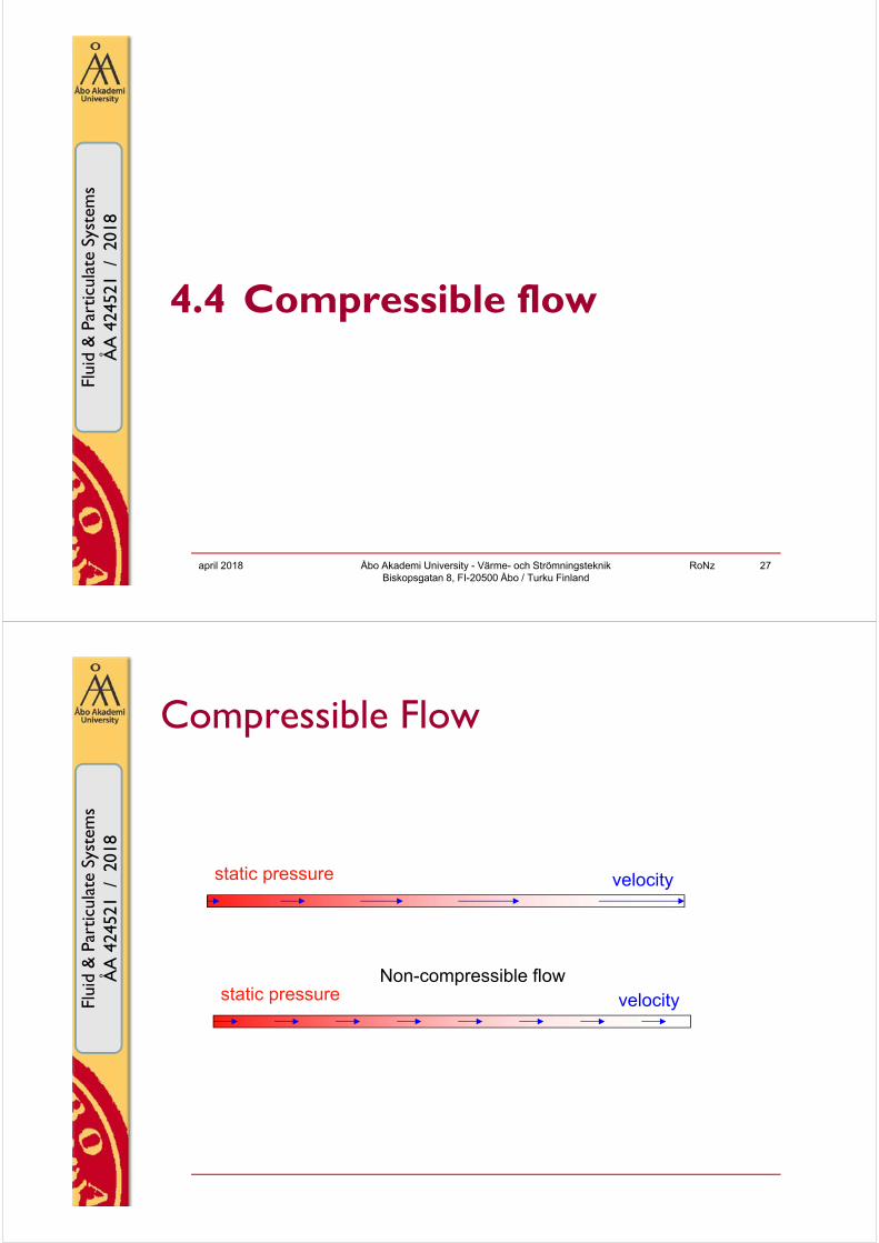
Compressible Flow
static pressure velocity
static pressure velocityNon-compressible flow

Flu
id &
Par
ticul
ate
Sys
tem
s42
4521
/ 2
010
Flui
d &
Par
ticul
ate
Syst
ems
ÅA
424
521
/ 2
018
Compressible fluid
p is highp is low
specific volume v is low(density high)
specific volume v is high(density low)
Concerns gases. Liquids are usually approximated as non-compressible.
april 2018 RoNz 29Åbo Akademi University - Värme- och Strömningsteknik Biskopsgatan 8, FI-20500 Åbo / Turku Finland
Flu
id &
Par
ticul
ate
Sys
tem
s42
4521
/ 2
010
Flui
d &
Par
ticul
ate
Syst
ems
ÅA
424
521
/ 2
018
Gas flow in a pipe calculations
The normal pressure balance can be used if Δp = p1 – p2 < 20%. Use then w and ρ pertaining at pmean; gas behaves like liquid
Calculate as a connection in series. Constant values of w and ρ can beassumed for each section. Temperature changes due to heat transfer canalso be accounted for.
1
2
static pressure velocity
p decreases → v increases → V increases → velocity w increases.
april 2018 RoNz 30Åbo Akademi University - Värme- och Strömningsteknik Biskopsgatan 8, FI-20500 Åbo / Turku Finland

Flu
id &
Par
ticul
ate
Sys
tem
s42
4521
/ 2
010
Flui
d &
Par
ticul
ate
Syst
ems
ÅA
424
521
/ 2
018
Calculations
dlw
ddp d
2
2
3 Consider the case in which the temperature is constant and the changes in the potential and kinetic energies between the in- and outlet can be neglected. The decrease in static pressure –dp for a thin slice dl of the pipe (duct) is equal to the loss of pressure due to fluid friction.
The velocity w of a flowing gas can anywhere in a pipe be expressed as a function of the pressure p and the state at the inlet p1, w1 (alternatively thestate at outlet p2, w2), using the ideal gas law, for molar mass M kg/kmol:.
TR
pM
V
nMTRnVp
The density ρ of a flowing gas can likewise anywhere in a pipe beexpressed as a function of the pressure p and the state at the inlet p1, ρ1
(alternatively the state at the outlet p2, ρ2), according to the ideal gas law.
31
Flu
id &
Par
ticul
ate
Sys
tem
s42
4521
/ 2
010
Flui
d &
Par
ticul
ate
Syst
ems
ÅA
424
521
/ 2
018
Calculations
loss,1p
dlw
ddp d
2
23 continued…
Integration of and expressing w=f(w1,p1,p),
and ρ = f(ρ1,p1,p), the pressure at the outlet p2 can be calculated if the state of the inlet “1” is known according to
where
)2( loss,1112 pppp
is the fictive pressure loss if the state at the
inlet would pertain for the whole pipe.
32
*see pages 65-68

Flu
id &
Par
ticul
ate
Sys
tem
s42
4521
/ 2
010
Flui
d &
Par
ticul
ate
Syst
ems
ÅA
424
521
/ 2
018
Calculations
loss,2p
dlw
ddp d
2
2
3 continued…
and expressing
w = f(w2, p2, p) and ρ = f(ρ2, p2, p), the pressure at the inlet p1 can be calculated if the state of the outlet “2” is known according to
where is the fictive pressure loss if the state at the
outlet would pertain for the whole pipe.
Alternatively, integration of
)2( loss,2221 pppp
33
Flu
id &
Par
ticul
ate
Sys
tem
s42
4521
/ 2
010
Flui
d &
Par
ticul
ate
Syst
ems
ÅA
424
521
/ 2
018
Mass flow always constant
5.1 34

Flu
id &
Par
ticul
ate
Sys
tem
s42
4521
/ 2
010
Flui
d &
Par
ticul
ate
Syst
ems
ÅA
424
521
/ 2
018
Temperature constant?
2211 VpVp
/122
/111
pTpT
122
111
VTVT
An isentropic expansion of an ideal gas would decrease the temperature in an isolated system.
An isentropic compression of an ideal gas would increase the temperature in an isolated system.
Isentropic changes from a beginning state “1” to an end state “2” can be described by
v
p
c
c
“1”
“2”
5.2 35
Flu
id &
Par
ticul
ate
Sys
tem
s42
4521
/ 2
010
Flui
d &
Par
ticul
ate
Syst
ems
ÅA
424
521
/ 2
018
Temperature constant?
The expansion of a flowing ideal gas in a pipe is not isentropic since the pressure loss due to fluid friction involves an entropy generation.
Temperature decrease due to expansion
Temperature increase due to fluid friction→ temperature remains constant
Changes in potential and kinetic energies are neglected.
The temperature increase for a real gas, e.g. air, can also be neglected.
5.3, 5.4 april 2018 RoNz 36Åbo Akademi University - Värme- och Strömningsteknik
Biskopsgatan 8, FI-20500 Åbo / Turku Finland
Flu
id &
Par
ticul
ate
Sys
tem
s42
4521
/ 2
010
Flui
d &
Par
ticul
ate
Syst
ems
ÅA
424
521
/ 2
018
4.5 Excercises 5
Åbo Akademi University - Värme- och Strömningsteknik Biskopsgatan 8, FI-20500 Åbo / Turku Finland
RoNz 37april 2018
Flu
id &
Par
ticul
ate
Sys
tem
s42
4521
/ 2
010
Flui
d &
Par
ticul
ate
Syst
ems
ÅA
424
521
/ 2
018
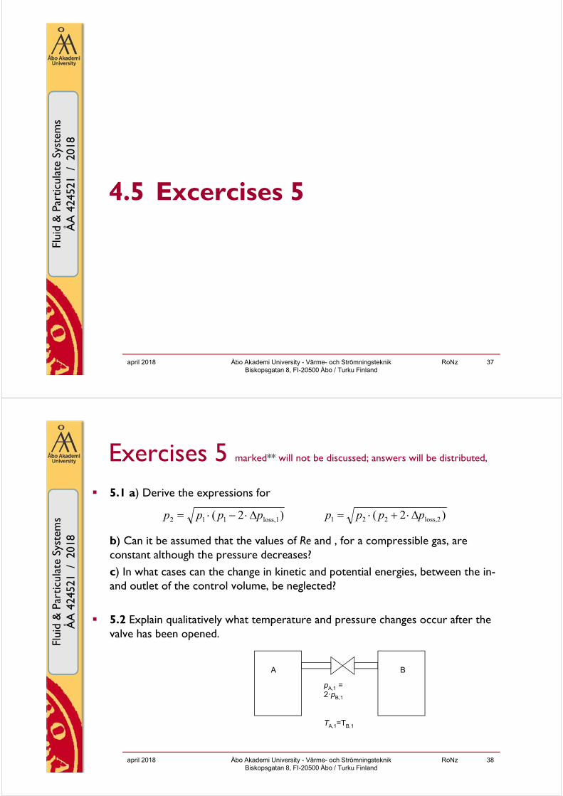
Exercises 5 marked** will not be discussed; answers will be distributed,
5.1 a) Derive the expressions for
b) Can it be assumed that the values of Re and , for a compressible gas, are constant although the pressure decreases?c) In what cases can the change in kinetic and potential energies, between the in-and outlet of the control volume, be neglected?
5.2 Explain qualitatively what temperature and pressure changes occur after the valve has been opened.
april 2018 Åbo Akademi University - Värme- och Strömningsteknik Biskopsgatan 8, FI-20500 Åbo / Turku Finland
RoNz 38
)2( loss,1112 pppp )2( loss,2221 pppp
pA,1 = 2ꞏpB,1
A B
TA,1=TB,1
Flu
id &
Par
ticul
ate
Sys
tem
s42
4521
/ 2
010
Flui
d &
Par
ticul
ate
Syst
ems
ÅA
424
521
/ 2
018
Exercises 5 5.3 What is special with the enthalpy of a flowing gas in a pipe?
**5.4 Air with a pressure of 600 kPa and a temperature of 200ºC is transported through a pipe (l=500 m, d=50 mm, roughness k=0.05 mm). The pressure at the outlet is 100 kPa.a) Calculate the mass flow rate under the assumption that the process is isothermal at 200ºC.b) Calculate the mass flow rate in a case where the surrounding air at 0ºC has a cooling influence; the heat transfer coefficient related to the inner surface of the pipe is assumed to be 3.0 W/(m2 K). Calculate the pressure distribution along the pipe.Pressure losses due to inlet, outlet and valves can be neglected.
april 2018 Åbo Akademi University - Värme- och Strömningsteknik Biskopsgatan 8, FI-20500 Åbo / Turku Finland
RoNz 39
Flu
id &
Par
ticul
ate
Sys
tem
s42
4521
/ 2
010
Flui
d &
Par
ticul
ate
Syst
ems
ÅA
424
521
/ 2
018
4.6 Momentum balances, the ejector
Åbo Akademi University - Värme- och Strömningsteknik Biskopsgatan 8, FI-20500 Åbo / Turku Finland
RoNz 40april 2018
Flu
id &
Par
ticul
ate
Sys
tem
s42
4521
/ 2
010
Flui
d &
Par
ticul
ate
Syst
ems
ÅA
424
521
/ 2
018
Applied Momentum BalancesF
luid
& P
artic
ulat
eS
yste
ms
4245
21 /
201
0Fl
uid
& P
artic
ulat
eSy
stem
sÅ
A 4
2452
1 /
201
8
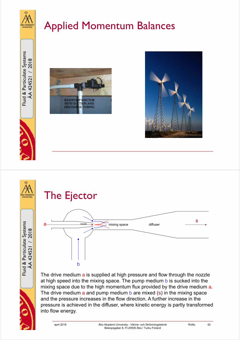
The Ejector
The drive medium a is supplied at high pressure and flow through the nozzle at high speed into the mixing space. The pump medium b is sucked into the mixing space due to the high momentum flux provided by the drive medium a. The drive medium a and pump medium b are mixed (s) in the mixing space and the pressure increases in the flow direction. A further increase in the pressure is achieved in the diffuser, where kinetic energy is partly transformed into flow energy.
a
b
smixing space diffusernozzle
april 2018 RoNz 42Åbo Akademi University - Värme- och Strömningsteknik Biskopsgatan 8, FI-20500 Åbo / Turku Finland

Flu
id &
Par
ticul
ate
Sys
tem
s42
4521
/ 2
010
Flui
d &
Par
ticul
ate
Syst
ems
ÅA
424
521
/ 2
018
The Ejector
a
b
smixing space diffusernozzle
“3”“2”“1”
“0”
“0”
If the drive medium a is steam, which condensates in the mixing space, the outletpressure p3 might reach values higher than the inlet pressure pa0 of the steam.This kind of ejector is called injector, which can be used as feed pump for steam boilers.
This is an easy and inexpensive pump to manufacture, and the operation is safesince it does not contain any moving parts. It has, however a low efficiency andit might be a negative aspect that the drive medium a is mixed together with thepump medium b.
april 2018 RoNz 43Åbo Akademi University - Värme- och Strömningsteknik Biskopsgatan 8, FI-20500 Åbo / Turku Finland
Flu
id &
Par
ticul
ate
Sys
tem
s42
4521
/ 2
010
Flui
d &
Par
ticul
ate
Syst
ems
ÅA
424
521
/ 2
018
The Ejector
Energy and momentum balances can be utilized as tools for picturing theworking boundaries and the efficiency of the ejector when put into practice.
Following ideal conditions are assumed:- densities are constant for the drive medium ρa and the pump medium ρb
- no losses due to fluid friction in the mixing space- kinetic energy and momentum ξ coefficients are assumed to be 1- ideal inflow; no losses when flow energy is transformed to kinetic energy
at boundary “1”- constant diffuser efficiency (80%)
april 2018 RoNz 44Åbo Akademi University - Värme- och Strömningsteknik Biskopsgatan 8, FI-20500 Åbo / Turku Finland

Flu
id &
Par
ticul
ate
Sys
tem
s42
4521
/ 2
010
Flui
d &
Par
ticul
ate
Syst
ems
ÅA
424
521
/ 2
018
The Ejector
a
b
smixing space diffusernozzle
“2”“1”
“0”
“0”“3”
7.145
Flu
id &
Par
ticul
ate
Sys
tem
s42
4521
/ 2
010
Flui
d &
Par
ticul
ate
Syst
ems
ÅA
424
521
/ 2
018
The Ejector
a
10aa1
2
pp
w
b
10bb1
2
pp
w
b1a1s2 1 www
s2
bb1aa1s
1
w
ww
2s2s
2b1b
2a1a12 1 wwwpp
2s2s23 4.0 wpp
b00a1
b03s2e ppw
ppw
a
7.2
The following equations can be utilized for calculations of ejectors.
46
)/m(m 22
cs
n
spacemixing
nozzle
A
A
A
A

Flu
id &
Par
ticul
ate
Sys
tem
s42
4521
/ 2
010
Flui
d &
Par
ticul
ate
Syst
ems
ÅA
424
521
/ 2
018
The Ejector (Injector)
If the drive or pump medium (or both) are gaseous (steam), changes in the specific volume (density) have to be accounted for.
In such case it might be appropriate to utilize energy and entropy balances for rough estimates of the ejector performance.
7.3april 2018 RoNz 47Åbo Akademi University - Värme- och Strömningsteknik
Biskopsgatan 8, FI-20500 Åbo / Turku Finland
Flu
id &
Par
ticul
ate
Sys
tem
s42
4521
/ 2
010
Flui
d &
Par
ticul
ate
Syst
ems
ÅA
424
521
/ 2
018
4.7 Momentum balances, propellors and wind turbines
see also ÅA course New Energy Technologies 424517and REN21 annual reports on renewable energy for windenergy status
Åbo Akademi University - Värme- och Strömningsteknik Biskopsgatan 8, FI-20500 Åbo / Turku Finland
RoNz 48april 2018
REN21

Flu
id &
Par
ticul
ate
Sys
tem
s42
4521
/ 2
010
Flui
d &
Par
ticul
ate
Syst
ems
ÅA
424
521
/ 2
018
april 2018 Åbo Akademi University - Värme- och Strömningsteknik Biskopsgatan 8, FI-20500 Åbo / Turku Finland
49/64
Wind energy – Betz’ Law
Theoretically (Betz’ Law) a wind turbine can exploit 60% (16/27) of incoming windpower.
In practice it is ~40%, due to (exergy) losses, mainly as heat, for example friction betweenrotor shaft and bearings, cooling fluids in gear box and generator.
Pic
s: h
ttp://
guid
edto
ur.w
indp
ower
.org
/en/
stat
/bet
zpro
.htm
Flu
id &
Par
ticul
ate
Sys
tem
s42
4521
/ 2
010
Flui
d &
Par
ticul
ate
Syst
ems
ÅA
424
521
/ 2
018
Power input P > 0 (boats, airplanes)
w1 undisturbedinput velocity w2 velocity at a
distance of ~ Dp
after the propeller
wp velocity throughthe propeller
“1”
“2”
“1” “2”
Sweep area ofthe propeller: 4
2p
p
DA
Dp
Input power PInput axle force F
april 2018 RoNz 50Åbo Akademi University - Värme- och Strömningsteknik Biskopsgatan 8, FI-20500 Åbo / Turku Finland

Flu
id &
Par
ticul
ate
Sys
tem
s42
4521
/ 2
010
Flui
d &
Par
ticul
ate
Syst
ems
ÅA
424
521
/ 2
018
Power output P < 0 (wind power plants)w1 undisturbedinput velocity
w2 velocity at a distance of ~ Dp
after the propeller“1”
“2”
Output power-POutput axle force-F
wp velocity throughthe propeller
“1” “2”
: mass flow if fluid through the propeller
april 2018 RoNz 51Åbo Akademi University - Värme- och Strömningsteknik Biskopsgatan 8, FI-20500 Åbo / Turku Finland
Flu
id &
Par
ticul
ate
Sys
tem
s42
4521
/ 2
010
Flui
d &
Par
ticul
ate
Syst
ems
ÅA
424
521
/ 2
018
Energy and momentum balancesThe simplified theory is based on the assumption that the propeller power is used for changing the kinetic energy (without losses) of the mass flow going through the sweep area of the propeller.
Idealizations: -The propeller is considered as a pump (η =100%) in a pipe with the diameter
Dp and the length 0- The kinetic energy coefficients ξ are assumed to be 1- Neglecting that the propeller jet is spinning around its axis (= power loss)- Neglecting the influence of the number of propeller wings- The pressure is constant along the balance boundaries. However, there is a
pressure difference Δp on both sides of the propeller distributed over thewhole sweep area
7.4april 2018 RoNz 52Åbo Akademi University - Värme- och Strömningsteknik
Biskopsgatan 8, FI-20500 Åbo / Turku Finland

Flu
id &
Par
ticul
ate
Sys
tem
s42
4521
/ 2
010
Flui
d &
Par
ticul
ate
Syst
ems
ÅA
424
521
/ 2
018
Velocity wp through the propeller
53
Flu
id &
Par
ticul
ate
Sys
tem
s42
4521
/ 2
010
Flui
d &
Par
ticul
ate
Syst
ems
ÅA
424
521
/ 2
018
Betz’ Law (1926)
P is power extracted from the wind
Power of undisturbed flow through area Ap
Efficiency of power exraction from wind
with maximum 16/27 at w2/w1=1/3
april 2018 Åbo Akademi University - Värme- och Strömningsteknik Biskopsgatan 8, FI-20500 Åbo / Turku Finland
RoNz 54
p2122
21airp21
22
21
air A)w½(www½ρA)w(www4
ρP
wAΔpwFAw2
ρP p
31
air0
)1(12
1
1
221
22
0 w
w
w
w
P
P

Flu
id &
Par
ticul
ate
Sys
tem
s42
4521
/ 2
010
Flui
d &
Par
ticul
ate
Syst
ems
ÅA
424
521
/ 2
018
Propeller pitch s (sv: stigning)
nsw p n: rotational speed
7.5
april 2018 RoNz 55Åbo Akademi University - Värme- och Strömningsteknik Biskopsgatan 8, FI-20500 Åbo / Turku Finland
Flu
id &
Par
ticul
ate
Sys
tem
s42
4521
/ 2
010
Flui
d &
Par
ticul
ate
Syst
ems
ÅA
424
521
/ 2
018
Recent developments
See S Langton „Fitting a pitch“ Mechanical Engineering (ASME) December 2009, p. 38-42
april 2018 Åbo Akademi University - Värme- och Strömningsteknik Biskopsgatan 8, FI-20500 Åbo / Turku Finland
RoNz 56
Flu
id &
Par
ticul
ate
Sys
tem
s42
4521
/ 2
010
Flui
d &
Par
ticul
ate
Syst
ems
ÅA
424
521
/ 2
018
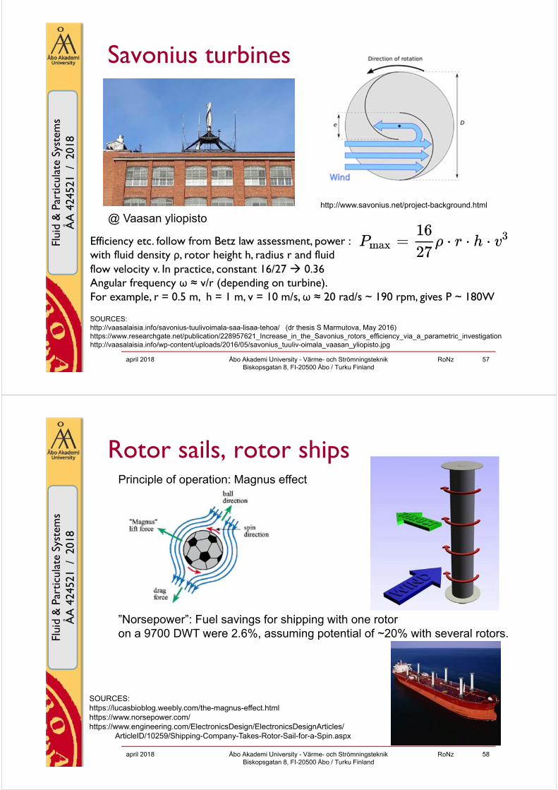
Savonius turbines
april 2018 Åbo Akademi University - Värme- och Strömningsteknik Biskopsgatan 8, FI-20500 Åbo / Turku Finland
RoNz 57
@ Vaasan yliopisto
SOURCES:http://vaasalaisia.info/savonius-tuulivoimala-saa-lisaa-tehoa/ (dr thesis S Marmutova, May 2016)https://www.researchgate.net/publication/228957621_Increase_in_the_Savonius_rotors_efficiency_via_a_parametric_investigationhttp://vaasalaisia.info/wp-content/uploads/2016/05/savonius_tuuliv-oimala_vaasan_yliopisto.jpg
Efficiency etc. follow from Betz law assessment, power :with fluid density ρ, rotor height h, radius r and fluid flow velocity v. In practice, constant 16/27 0.36Angular frequency ω ≈ v/r (depending on turbine).For example, r = 0.5 m, h = 1 m, v = 10 m/s, ω ≈ 20 rad/s ~ 190 rpm, gives P ~ 180W
http://www.savonius.net/project-background.html
Flu
id &
Par
ticul
ate
Sys
tem
s42
4521
/ 2
010
Flui
d &
Par
ticul
ate
Syst
ems
ÅA
424
521
/ 2
018
Rotor sails, rotor ships
april 2018 Åbo Akademi University - Värme- och Strömningsteknik Biskopsgatan 8, FI-20500 Åbo / Turku Finland
RoNz 58
Principle of operation: Magnus effect
”Norsepower”: Fuel savings for shipping with one rotoron a 9700 DWT were 2.6%, assuming potential of ~20% with several rotors.
SOURCES:https://lucasbioblog.weebly.com/the-magnus-effect.htmlhttps://www.norsepower.com/https://www.engineering.com/ElectronicsDesign/ElectronicsDesignArticles/
ArticleID/10259/Shipping-Company-Takes-Rotor-Sail-for-a-Spin.aspx

Flu
id &
Par
ticul
ate
Sys
tem
s42
4521
/ 2
010
Flui
d &
Par
ticul
ate
Syst
ems
ÅA
424
521
/ 2
018
4.8 Excercises 7
Åbo Akademi University - Värme- och Strömningsteknik Biskopsgatan 8, FI-20500 Åbo / Turku Finland
RoNz 59april 2018
Flu
id &
Par
ticul
ate
Sys
tem
s42
4521
/ 2
010
Flui
d &
Par
ticul
ate
Syst
ems
ÅA
424
521
/ 2
018
Exercises 7 marked** will not be discussed; answers will be distributed
7.1 Derive equations for evaluating the ejector pump in practice.
7.2 An ejector pump is used for emptying a flooded basement floor. The drive medium consists of tap water with a pressure pa0 of 900 kPa. A suitable inlet pressure pb0 of the pump medium would be 80 kPa, and the outlet pressure p3 is expected to be 130 kPa. The tap water flow is 1 l/s. Design the ejector (calculate Acs and Acs,a) that maximizes the mass flow rate of the pump medium.
april 2018 Åbo Akademi University - Värme- och Strömningsteknik Biskopsgatan 8, FI-20500 Åbo / Turku Finland
RoNz 60
a
b
smixing space diffusernozzle
“2”“1”
“0”
“0”“3”

Flu
id &
Par
ticul
ate
Sys
tem
s42
4521
/ 2
010
Flui
d &
Par
ticul
ate
Syst
ems
ÅA
424
521
/ 2
018
Exercises 7 **7.3 A steam injector is consuming 0.105 kg/s saturated drive medium steam
with a pressure of 420 kPa for compression of 0.120 kg/s wet steam (containing 2% water) with a temperature of 15ºC to the pressure of 4.0 kPa.a) Calculate the temperature of the out coming steam at 4.0 kPab) Calculate the efficiency of the injector by comparing the turbine power, which the drive medium steam (0.105 kg/s) would theoretically give off at an isentropic expansion to 4.0 kPa, with the compressor power, which would be needed for isentropic compression of 0.120 kg/s steam to 4.0 kPa.
7.4 Derive momentum balances fora)
april 2018 Åbo Akademi University - Värme- och Strömningsteknik Biskopsgatan 8, FI-20500 Åbo / Turku Finland
RoNz 61
w1 undisturbedinput velocity w2 velocity at a
distance of ~ Dpafter the propeller
“1”
“2”
Input power PInput axle force F
Flu
id &
Par
ticul
ate
Sys
tem
s42
4521
/ 2
010
Flui
d &
Par
ticul
ate
Syst
ems
ÅA
424
521
/ 2
018
Exercises 7 7.4 Derive momentum balances for
a)
b)
c) What is the relationship between the power (input or output) P and the pressure difference Δp on both sides of the propeller?
april 2018 Åbo Akademi University - Värme- och Strömningsteknik Biskopsgatan 8, FI-20500 Åbo / Turku Finland
RoNz 62
w1 undisturbedinput velocity
w2 velocity at a distance of ~ Dpafter the propeller
“1”
“2”
Output power -POutput axle force -F
wp velocity throughthe propeller
“1” “2”

Flu
id &
Par
ticul
ate
Sys
tem
s42
4521
/ 2
010
Flui
d &
Par
ticul
ate
Syst
ems
ÅA
424
521
/ 2
018
Exercises 7
**7.5 A wind motor has a propeller diameter of 6 m.a) How much axle power can theoretically be achieved if the wind flow (0 ºC) is w1 8 m/s and the wind velocity w2 (ca 6 m after the propeller) is 2 m/s.b) What will the rotational speed be if the propeller pitch is 15 m.c) Is w2 = 2 m/s optimal? What w2 would be optimal for reaching maximum power output?d) Show that the maximum power output is 16/27 (=59%) of the kinetic energy that an air flow is possessing, that undisturbed with the velocity w1 is flowing through a ring with the propeller diameter Dp.
april 2018 Åbo Akademi University - Värme- och Strömningsteknik Biskopsgatan 8, FI-20500 Åbo / Turku Finland
RoNz 63
Flu
id &
Par
ticul
ate
Sys
tem
s42
4521
/ 2
010
Flui
d &
Par
ticul
ate
Syst
ems
ÅA
424
521
/ 2
018
Further reading DWIA09 “Proof of Betz’ Law” Danish Wind Industry Association
http://guidedtour.windpower.org/en/stat/betzpro.htm
KJ05: D. Kaminski, M. Jensen ”Introduction to Thermal and Fluids Engineering”, Wiley (2005) Chapter 4, chapter 10
L09: S Langton „Fitting a pitch“ Mechanical Engineering (ASME) December 2009, p. 38-42 (as pdf at course material www)
SWE = magazine Sun & Wind Energy http://www.sunwindenergy.com T06: S.R. Turns ”Thermal – Fluid Sciences”, Cambridge Univ. Press (2006) Z13: R. Zevenhoven ”Introduction to process engineering / Processteknikens
grunder” (PTG), # 6: Fluid mechanics: fluid statics, fluid dynamics. Course material ÅA (version 2013) available on line http://users.abo.fi/rzevenho/PTG%20Aug2013.pdf
ÖS96: G. Öhman, H. Saxén ”Värmeteknikens grunder”, Course compendium ÅA (1996)
Ö96: G. Öhman ”Teknisk strömningslära” Course compendium ÅA (1996) sections 3, 4, 7 (p. 8-14, 22-26)
CEWR10: C.T. Crowe, D.F. Elger, B.C. Williams, J.A. Roberson ”Engineering Fluid Mechanics”, 9th ed., Wiley (2010)
REN21: Renewables 2017 Global Status Report (GSR 2017) http://www.ren21.net/wp-content/uploads/2017/06/17-8399_GSR_2017_Full_Report_0621_Opt.pdf (302 pages)http://www.ren21.net/status-of-renewables/global-status-report/ (links to Figures etc.)
april 2018 Åbo Akademi University - Värme- och StrömningsteknikBiskopsgatan 8, FI-20500 Åbo / Turku Finland
RoNz 64

Flu
id &
Par
ticul
ate
Sys
tem
s42
4521
/ 2
010
Flui
d &
Par
ticul
ate
Syst
ems
ÅA
424
521
/ 2
018
Add: compressible flow pressure drop
april 2018 Åbo Akademi University - Värme- och Strömningsteknik Biskopsgatan 8, FI-20500 Åbo / Turku Finland
RoNz 65
Flu
id &
Par
ticul
ate
Sys
tem
s42
4521
/ 2
010
Flui
d &
Par
ticul
ate
Syst
ems
ÅA
424
521
/ 2
018
Add: compressible flow pressure drop
april 2018 Åbo Akademi University - Värme- och Strömningsteknik Biskopsgatan 8, FI-20500 Åbo / Turku Finland
RoNz 66

Flu
id &
Par
ticul
ate
Sys
tem
s42
4521
/ 2
010
Flui
d &
Par
ticul
ate
Syst
ems
ÅA
424
521
/ 2
018
Add: compressible flow pressure drop
april 2018 Åbo Akademi University - Värme- och Strömningsteknik Biskopsgatan 8, FI-20500 Åbo / Turku Finland
RoNz 67
Flu
id &
Par
ticul
ate
Sys
tem
s42
4521
/ 2
010
Flui
d &
Par
ticul
ate
Syst
ems
ÅA
424
521
/ 2
018
Add: compressible flow pressure drop
april 2018 Åbo Akademi University - Värme- och Strömningsteknik Biskopsgatan 8, FI-20500 Åbo / Turku Finland
RoNz 68