4200T CNC Programming and Operations Manual Page/Manuals/4200...4200T CNC Programming and Operations...
366
www.anilam.com 4200T CNC Programming and Operations Manual
Transcript of 4200T CNC Programming and Operations Manual Page/Manuals/4200...4200T CNC Programming and Operations...

www.anilam.com
4200T CNC Programming and Operations Manual


4200T CNC Programming and Operations Manual P/N 70000412G - Contents
All rights reserved. Subject to change without notice. iii October 2009
Section 1 - Programming Concepts Introduction ...................................................................................................................................... 1-1
Programs ...................................................................................................................................... 1-1 Axis Descriptions .............................................................................................................................. 1-2
Z Axis ............................................................................................................................................ 1-2 C Axis ........................................................................................................................................... 1-2 X Axis ........................................................................................................................................... 1-3
Part Zero Definition .......................................................................................................................... 1-3 Polar Coordinates ............................................................................................................................ 1-4 Absolute Positioning ......................................................................................................................... 1-5 Incremental Positioning .................................................................................................................... 1-6 Diameter or Radius Programming .................................................................................................... 1-6 Developing Part Programs ............................................................................................................... 1-7
Section 2 - CNC Console and Software Basics CNC Console ................................................................................................................................... 2-1 Keypad ............................................................................................................................................. 2-2
Alphanumeric Keys ....................................................................................................................... 2-3 Editing Keys .................................................................................................................................. 2-5 Using the Keypad to Program Moves ........................................................................................... 2-5 Soft Keys ...................................................................................................................................... 2-6 Accessing Keypad Commands Using a PC Keyboard (Optional) ................................................. 2-6
Software Basics ............................................................................................................................... 2-6 Pop-up Menus .............................................................................................................................. 2-7 Screen Saver ................................................................................................................................ 2-7 Highlight Bars ............................................................................................................................... 2-7 Cursors ......................................................................................................................................... 2-7 Clearing Entries ............................................................................................................................ 2-7 Operator Prompts ......................................................................................................................... 2-7 Typeover and Insert Modes .......................................................................................................... 2-8 Deleting Text ................................................................................................................................. 2-8 Messages/Error Messages ........................................................................................................... 2-8
Section 3 - Manual Operation and Machine Setup Manual Panel ................................................................................................................................... 3-1
Manual Panel Keys ....................................................................................................................... 3-2 Manual Panel LEDs ...................................................................................................................... 3-3
Manual Mode Screen ....................................................................................................................... 3-4 Machine Status Display Area Labels ............................................................................................ 3-5 Program Area Labels .................................................................................................................... 3-6
Powering on the CNC ...................................................................................................................... 3-6 Shutting Down the CNC ................................................................................................................... 3-7 Setting/Resetting the Emergency Stop (E-STOP) ............................................................................ 3-7 Activating/Resetting the Servos ....................................................................................................... 3-7

4200T CNC Programming and Operations Manual P/N 70000412G - Contents
iv All rights reserved. Subject to change without notice.
October 2009
Manual Mode Settings ..................................................................................................................... 3-7 Activating Manual Mode Rapid or Feed ........................................................................................ 3-8 Adjusting the Feedrate .................................................................................................................. 3-8 Adjusting Rapid Move Speed ........................................................................................................ 3-9 Setting Absolute Zero ................................................................................................................. 3-10 Part Zero ..................................................................................................................................... 3-10
Jog Moves ...................................................................................................................................... 3-11 Changing the Jog Mode .............................................................................................................. 3-11 Selecting an Axis ........................................................................................................................ 3-11 Jogging the Machine (in Increments) .......................................................................................... 3-12 Jogging the Machine (Continuous Moves) .................................................................................. 3-12
Manual Data Input (MDI) Mode ...................................................................................................... 3-12 Using Manual Data Input Mode .................................................................................................. 3-13
Handwheel Operation .................................................................................................................... 3-13 Operating a Handwheel Mounted on the Manual Panel ............................................................. 3-13 Operating Handwheels Mounted on the Machine ....................................................................... 3-14
Section 4 - Preparatory Functions: G-Codes Preparatory Functions: G-Codes ...................................................................................................... 4-1
Rapid Traverse (G0) ..................................................................................................................... 4-3 Linear Interpolation (G1) ............................................................................................................... 4-4 Angular Motion Programming Example ........................................................................................ 4-5 Circular Interpolation (G2 and G3) ............................................................................................... 4-6 Partial Arcs ................................................................................................................................... 4-8 Dwell (G4) ..................................................................................................................................... 4-8 Ellipse (G5) ................................................................................................................................... 4-9 Non-modal Exact Stop Check (G9) ............................................................................................. 4-10 Setting Software Limits (G22) ..................................................................................................... 4-11 Maximum Spindle Speed (G24) .................................................................................................. 4-12 Probe Move (G31) ...................................................................................................................... 4-13 Thread Cutting (G33) .................................................................................................................. 4-13 Offsets (Work Coordinate System Select) (G53) ........................................................................ 4-14 Modal Corner Rounding/Chamfering (G59) ................................................................................ 4-16 Cancel Modal Corner Rounding (G60) ....................................................................................... 4-18 In-Position Mode (Exact Stop Check) (G61) ............................................................................... 4-18 Contouring Mode (Cutting Mode) (G64) ..................................................................................... 4-19 Using Macros (G65, G66, G67) ................................................................................................. 4-20 Inch Mode (G70) or MM Mode (G71) .......................................................................................... 4-22 Absolute Mode (G90) or Incremental Mode (G91) ...................................................................... 4-22 Presetting the Axes (G92)........................................................................................................... 4-24 Cutting Feedrates in Feed per Minute (G94) .............................................................................. 4-25 Cutting Feedrates in Feed Per Revolution (G95) ........................................................................ 4-25 Setting Spindle Speed to Constant Surface Speed (G96) .......................................................... 4-26 Setting Spindle Speed to Constant Revolutions Per Minute Speed (G97) .................................. 4-26
Section 5 - Canned Cycles Programming a Z-Axis Turning/Boring Cycle with a Defined Profile (G73) ...................................... 5-1 Programming an X-Axis Facing/Boring Cycle with Defined Profile (G74) ........................................ 5-4 Programming a Z-Axis Rough Turning or Boring Cycle (G76) ......................................................... 5-7 Programming an X-Axis Radial (Facing) Roughing Cycle (G77) ...................................................... 5-9

4200T CNC Programming and Operations Manual P/N 70000412G - Contents
All rights reserved. Subject to change without notice. v October 2009
Programming a Pecking Cycle (G78) ............................................................................................. 5-11 Programming a Chip Break Cycle (G79) ........................................................................................ 5-12 Programming a Longitudinal Grooving Cycle (G81) ....................................................................... 5-13 Programming a Radial Grooving Cycle (G82) ................................................................................ 5-15 Types of Threading ........................................................................................................................ 5-17
Cutting Longitudinal Threads with Canned Cycles (G83, Uni-directional) .................................. 5-18 Cutting Longitudinal Threads with Canned Cycles (G84, Bi-directional) ..................................... 5-20 Cutting Radial Threads with Canned Cycles (G85, Uni-directional) ............................................ 5-23 Cutting Radial Threads with Canned Cycles (G86, Bi-directional) .............................................. 5-26
Tapping a Hole with a Canned Cycle (G87) ................................................................................... 5-28 Programming a Boring Cycle (G88) ............................................................................................... 5-30 Lathe Tool Probe Cycles (Option) .................................................................................................. 5-32
Tool Probe G-code Cycle Designations ...................................................................................... 5-33 Macro Variable and System Variable Settings ............................................................................ 5-33 Probe Orientation ........................................................................................................................ 5-35 Lathe Tool Probe G-code Cycle Designations ............................................................................ 5-35 Description of Tool Probe Cycles ................................................................................................ 5-37
Section 6 - Program Editor Activating the Program Editor ........................................................................................................... 6-1
Activating the Edit Mode from the Manual Screen ........................................................................ 6-1 Activating the Edit Mode from the Program Directory ................................................................... 6-1 Activating the Edit Mode from Draw Graphics .............................................................................. 6-1
Edit Soft Keys ................................................................................................................................... 6-3 Editing Shift Soft Keys .................................................................................................................. 6-4
Deleting a Character ........................................................................................................................ 6-4 Inserting Text to Overwrite Previous Text ........................................................................................ 6-4
Inserting Text without Overwriting Previous Text .......................................................................... 6-4 Deleting a Program Block................................................................................................................. 6-5 Page Up/Down through the Program Listing ................................................................................... 6-5 Going to a Line of the Program Listing ............................................................................................. 6-6 Advancing to the Beginning or End of a Block ................................................................................. 6-6 Advancing to the First or Last Block of a Program ........................................................................... 6-6 Searching the Program Listing for Selected Text ............................................................................. 6-7 Inserting a Blank Line in the Program Listing ................................................................................... 6-7 Restoring a Block ............................................................................................................................. 6-8 Replacing Typed Text with New Text ............................................................................................... 6-8 Abbreviating Statements .................................................................................................................. 6-9 Marking (Highlighting) Programming Blocks .................................................................................. 6-10
Unmarking Program Blocks ........................................................................................................ 6-10 Canceling Edits to a Program Block ............................................................................................... 6-10 Scrolling Through the Program Listing ........................................................................................... 6-10

4200T CNC Programming and Operations Manual P/N 70000412G - Contents
vi All rights reserved. Subject to change without notice.
October 2009
Copying Program Blocks ................................................................................................................ 6-11 Printing a Portion of a Program ...................................................................................................... 6-12 Pasting Copied Blocks into a Program Listing ................................................................................ 6-12 Numbering (or Re-numbering) Program Blocks ............................................................................. 6-13 Writing Blocks to Another Program ................................................................................................ 6-13 Reading a Program into Another Program .................................................................................... 6-14 Recording Keystrokes .................................................................................................................... 6-14
Playing Recorded Keystrokes ..................................................................................................... 6-15 Repeating a Command or Key ....................................................................................................... 6-15 Printing an Entire Program Listing .................................................................................................. 6-15 Accessing the Most Recently Used Programs ............................................................................... 6-16 Opening Another Program from the Program Listing ..................................................................... 6-16 Saving Edits ................................................................................................................................... 6-16 Canceling Unsaved Edits ............................................................................................................... 6-17 Including Comments in a Program Listing ...................................................................................... 6-17
Section 7 - Edit Help Edit Help Menu ................................................................................................................................. 7-4
Edit Help Soft Keys ....................................................................................................................... 7-8 Help Template Menu ........................................................................................................................ 7-9 Help Graphic Screens .................................................................................................................... 7-11 Using Help Graphic Screens to Enter Program Blocks .................................................................. 7-13 Available Help Graphic Screens ..................................................................................................... 7-14
Programming Modal G-Codes in Edit Help ................................................................................. 7-37 Programming LINE Moves in Edit Help ...................................................................................... 7-38 Angle Direction for Front and Rear Tool Posts ........................................................................... 7-39 Using Angles to Program Moves ................................................................................................ 7-41 Programming MULTIPLE Move Commands in Edit Help ........................................................... 7-42
Section 8 - Draw Mode Introduction ...................................................................................................................................... 8-1 Starting Draw ................................................................................................................................... 8-2 Draw Screen Description .................................................................................................................. 8-2
Putting Draw in Hold ..................................................................................................................... 8-3 Restarting Draw When in Hold ...................................................................................................... 8-3 Canceling Draw ............................................................................................................................ 8-3
Draw Parameters ............................................................................................................................. 8-4 Tool On or Off ............................................................................................................................... 8-4 Drawing Compensated Moves ...................................................................................................... 8-5 Showing Rapid Moves .................................................................................................................. 8-5 Setting Grid Line Type .................................................................................................................. 8-5 Setting Grid Size ........................................................................................................................... 8-6 Putting Draw in Motion, S.Step, or Auto Mode .............................................................................. 8-6

4200T CNC Programming and Operations Manual P/N 70000412G - Contents
All rights reserved. Subject to change without notice. vii October 2009
Automatic Draw Restart ................................................................................................................ 8-7 Erasing the Draw Display.............................................................................................................. 8-7 Running Draw for Selected Blocks ............................................................................................... 8-7 Starting Draw at a Specific Block .................................................................................................. 8-8 Ending Draw at a Specific Block ................................................................................................... 8-8
Adjusting Draw Display .................................................................................................................... 8-8 Fitting the Display to the Viewing Window .................................................................................... 8-9 Halving Display Size ..................................................................................................................... 8-9 Doubling Display Size ................................................................................................................... 8-9 Scaling the Display by a Factor .................................................................................................... 8-9 Using the Window Zoom ............................................................................................................. 8-10 Erasing Display ........................................................................................................................... 8-10 Changing the Viewing Area without Changing the Scale ............................................................ 8-11
Section 9 - Tool Page and Tool Management Activating the Tool Page .................................................................................................................. 9-1 Using the Tool Page ......................................................................................................................... 9-1
Entering Values in the Tool Page ................................................................................................. 9-3 Adjusting a Single Value ............................................................................................................... 9-3
Finding Tools by Number ................................................................................................................. 9-3 Clearing Tool Information (Delete Row) ........................................................................................... 9-4
Clearing a Value from a Column ................................................................................................... 9-4 Clearing the Whole Tool Page ...................................................................................................... 9-4
Tool-Length Offsets .......................................................................................................................... 9-4 Setting Tool-Length Offsets .......................................................................................................... 9-5 Entering Tool Page TLO’s Using the Calibration Function ............................................................ 9-6 Entering Tool Page TLO’s Manually ............................................................................................. 9-6 Tool Offset Modification ................................................................................................................ 9-7
Activating a Tool Number in the Manual Mode ................................................................................. 9-8 Deactivating TLO’s in the Manual Mode ....................................................................................... 9-8
Tool Nose Radius (TNR) Compensation .......................................................................................... 9-8 Selecting a Tool Location Code .................................................................................................. 9-11 Tool Nose Radius Programming Examples ................................................................................ 9-12 Left of Path TNR Program (G41) ................................................................................................ 9-13 Right of Path TNR Program (G42) .............................................................................................. 9-15 Canceling Tool Nose Radius Compensation (G40) .................................................................... 9-17 Choosing the Correct TNR Compensation ................................................................................. 9-18 Changing TNR Compensation in a Program............................................................................... 9-18 Motion of Tool during TNR Compensation .................................................................................. 9-20 Compensation around Acute Angles .......................................................................................... 9-21 Changing the Numbers of Look Ahead Blocks ........................................................................... 9-22
Wear Offsets .................................................................................................................................. 9-22 Setting Wear Offset Adjustment While Running a Program ........................................................ 9-23
Section 10 - Program Management Changing the Program Directory’s Display ..................................................................................... 10-1 Creating a New Part Program ........................................................................................................ 10-2
Choosing Program Names .......................................................................................................... 10-2

4200T CNC Programming and Operations Manual P/N 70000412G - Contents
viii All rights reserved. Subject to change without notice.
October 2009
Selecting a Program for Running ................................................................................................... 10-2 Selecting a Program for Editing and Utilities .................................................................................. 10-3 Listing a Program ........................................................................................................................... 10-3 Deleting a Program ........................................................................................................................ 10-3 Logging to Other Drives ................................................................................................................. 10-4 Marking and Unmarking Programs ................................................................................................. 10-5
Marking Programs ...................................................................................................................... 10-5 Unmarking Marked Programs ..................................................................................................... 10-5 Marking All Programs ................................................................................................................. 10-5 Unmarking All Marked Programs ................................................................................................ 10-5
Deleting Groups of Programs ......................................................................................................... 10-6 Restoring Programs ....................................................................................................................... 10-6 Copying Programs to Floppy Disks ................................................................................................ 10-6 Renaming Programs ...................................................................................................................... 10-7 Printing Programs .......................................................................................................................... 10-7 Formatting Floppy Disks................................................................................................................. 10-8 Checking Disks for Lost Program Fragments ................................................................................. 10-8 Displaying System Information ....................................................................................................... 10-9 Copying Programs from/to Unspecified Locations ....................................................................... 10-10 Renaming Programs from/to Unspecified Locations .................................................................... 10-10 Printing Programs from Unspecified Locations ............................................................................ 10-11 Creating Subdirectories ................................................................................................................ 10-11 Deleting an Unspecified Program ................................................................................................. 10-12 Listing an Unspecified Program ................................................................................................... 10-12 Editing an Unspecified Program ................................................................................................... 10-12 Optimizing Your Hard Disk ........................................................................................................... 10-13
Accessing the Disk Optimizer ................................................................................................... 10-13 Maximizing Program Storage Space ............................................................................................ 10-14
Section 11 - Running Programs Running a Program One Step at a Time ........................................................................................ 11-1
Toggling Between Motion and Single-Step Mode ....................................................................... 11-2 Holding or Canceling a Single-Step Run .................................................................................... 11-2
Single-Step Execution of Selected Program Blocks ....................................................................... 11-3 Using Arrow Keys to Select Starting Block ................................................................................. 11-3 Using Search to Select Starting Block ........................................................................................ 11-3 Switching from Single-Step to Auto ............................................................................................ 11-3
Position Display .............................................................................................................................. 11-4 Automatic Program Execution ........................................................................................................ 11-4
Holding or Canceling an Auto Run .............................................................................................. 11-5

4200T CNC Programming and Operations Manual P/N 70000412G - Contents
All rights reserved. Subject to change without notice. ix October 2009
Automatic Execution Starting at a Specific Block ........................................................................... 11-5 Using Arrow Keys to Select Starting Block ................................................................................. 11-5 Using SEARCH to Select Starting Block ..................................................................................... 11-5
Clearing a Halted Program ............................................................................................................. 11-5 Using Draw while Running Programs ............................................................................................. 11-6 Setting the CNC to Display an Enlarged Position Display .............................................................. 11-6 Teach Mode ................................................................................................................................... 11-7
Initiating Teach-In ....................................................................................................................... 11-7 Soft Keys of Teach-In ................................................................................................................. 11-7 Inputting Data into a Program ..................................................................................................... 11-7 Canceling Teach Mode ............................................................................................................... 11-8 About Teach Mode ..................................................................................................................... 11-8
Parts Counter and Program Timer ................................................................................................. 11-9 Background Mode ........................................................................................................................ 11-10
Section 12 - S Function, M Functions, and C-Axis Programming Introduction .................................................................................................................................... 12-1 Spindle Speed Control (S-Function) ............................................................................................... 12-1 Miscellaneous Functions (M-Codes) .............................................................................................. 12-2 Control M-Codes ............................................................................................................................ 12-2
Order of Execution ...................................................................................................................... 12-3 C-Axis Programming ...................................................................................................................... 12-3
Enabling C-Axis Programming Mode .......................................................................................... 12-3 Disabling C-Axis Programming Mode ......................................................................................... 12-3 C-Axis Jog .................................................................................................................................. 12-4 Programming C-Axis Feedrate ................................................................................................... 12-4 Synchronizing/Unsynchronizing C-Axis ...................................................................................... 12-4
Section 13 - Simplified Command Interface (SCI) Mode Activating the SCI Mode ................................................................................................................. 13-1 SCI Mode Soft Keys ....................................................................................................................... 13-3
Activating the SHIFT SCI Soft Key Menu ................................................................................... 13-3 Deactivating the SCI Mode ............................................................................................................. 13-4 Canceling an SCI Command .......................................................................................................... 13-4 Canceling a Running SCI Command ............................................................................................. 13-4 Clearing Messages ........................................................................................................................ 13-4 Clearing an Entry Field ................................................................................................................... 13-4 Returning to the Software Selection Screen ................................................................................... 13-4 Exiting SCI Mode ........................................................................................................................... 13-5 Commanding Moves in SCI Mode .................................................................................................. 13-5
Performing Rapid Moves (G00) .................................................................................................. 13-5 Activating and Changing a Tool .................................................................................................. 13-5 Performing Line Moves (G01) ..................................................................................................... 13-6

4200T CNC Programming and Operations Manual P/N 70000412G - Contents
x All rights reserved. Subject to change without notice.
October 2009
Performing Arc Moves (G02 or G03) .......................................................................................... 13-6 Setting Software Limits (G22) ..................................................................................................... 13-7 Homing the Machine (G28) ......................................................................................................... 13-9 Making a Rough Turning Cut (G76) ............................................................................................ 13-9 Making a Rough Facing Cut (G77) ........................................................................................... 13-10 Cutting Threads (G83) .............................................................................................................. 13-11 Activating Absolute (G90) or Incremental (G91) Mode ............................................................. 13-12 Setting the Feedrate to Feed per Minute (G94) ........................................................................ 13-12 Setting the Feedrate to Feed per Revolution (G95) .................................................................. 13-13 Setting Spindle Speed to Constant Surface Speed (G96) ........................................................ 13-13 Setting the Spindle Speed to Revolutions per Minute (G97) ..................................................... 13-14
Slave Mode .................................................................................................................................. 13-14 Cutting a Taper ......................................................................................................................... 13-15 Cutting a Chamfer ..................................................................................................................... 13-16 Cutting a Radius ....................................................................................................................... 13-17
Section 14 - Shape Editor Activating the Shape Editor ............................................................................................................ 14-2 Shape Terminology ........................................................................................................................ 14-3 Using the Pointer ............................................................................................................................ 14-3 Selecting Editing Tools ................................................................................................................... 14-4 Line Tools ....................................................................................................................................... 14-6 Arc Tools ........................................................................................................................................ 14-8 Arc Tools ........................................................................................................................................ 14-9 Chamfering Corners ....................................................................................................................... 14-9 Example #1, Creating a Basic Shape ........................................................................................... 14-10 Reversing an Arc’s Direction ........................................................................................................ 14-13 Deleting a Shape .......................................................................................................................... 14-13 Projecting Line Segments (Restoring Sharp Corners) ................................................................. 14-14 Joining Line Segments ................................................................................................................. 14-14 Importing Shapes from Other Programs....................................................................................... 14-14 Deleting a Segment ...................................................................................................................... 14-15 Changing the Shape Editor View ................................................................................................. 14-15 Viewing a List of Shape Segment Details .................................................................................... 14-15 Deactivating and Activating Shapes ............................................................................................. 14-16 Using Construction Geometry ...................................................................................................... 14-16 Accessing Geometry Tools .......................................................................................................... 14-16 Point Tools ................................................................................................................................... 14-17 Line Tools ..................................................................................................................................... 14-18 Circle Tools .................................................................................................................................. 14-19 Example #2, Creating Construction Geometry and Chaining it Into a Shape ............................... 14-20
Creating Construction Geometry .............................................................................................. 14-20

4200T CNC Programming and Operations Manual P/N 70000412G - Contents
All rights reserved. Subject to change without notice. xi October 2009
Chaining Geometry Elements to Create a Shape ........................................................................ 14-26 Viewing a Listing of Geometry Elements ...................................................................................... 14-28 Deleting Geometry Elements ....................................................................................................... 14-28 Deleting All Geometry Elements .................................................................................................. 14-29 Activate/Deactivating Geometry Elements ................................................................................... 14-29 Shape Editor Hot Keys ................................................................................................................. 14-29 Exiting the Shape Editor ............................................................................................................... 14-30 Executing Shapes in a Program ................................................................................................... 14-30 Managing Shape Files ................................................................................................................. 14-31
Naming Shape Files ................................................................................................................. 14-31 Viewing Shape Files in the Program Directory .......................................................................... 14-31 Deleting Shape Files ................................................................................................................. 14-32
Backing Up Shapes ...................................................................................................................... 14-32 Shape Editor Settings .................................................................................................................. 14-32 Verifying Shapes .......................................................................................................................... 14-33
Section 15 - Communication Introduction .................................................................................................................................... 15-1 Installing the RS-232 Cable ............................................................................................................ 15-1 Accessing the Communication Utilities .......................................................................................... 15-2 Setting Communication Parameters ............................................................................................... 15-3
Communication Port ................................................................................................................... 15-3 Baud ........................................................................................................................................... 15-3 Parity .......................................................................................................................................... 15-4 Data Bits ..................................................................................................................................... 15-4 Stop Bits ..................................................................................................................................... 15-4 Settings ....................................................................................................................................... 15-4 Data Type ................................................................................................................................... 15-4
Testing the Data Link ..................................................................................................................... 15-5 Activating the Test Link Screen ...................................................................................................... 15-5
Setting Test Link Display Modes ................................................................................................. 15-5 Testing the Link .......................................................................................................................... 15-6 Clearing the Receive Area .......................................................................................................... 15-6 Clearing the Transmit Area ......................................................................................................... 15-6
Sending a Program ........................................................................................................................ 15-6 Receiving a Program ...................................................................................................................... 15-6 Setting the Transmission and Receiving Display ........................................................................... 15-7
Holding Transmission/Receiving Operations .............................................................................. 15-7 Using Data Control (DC) Codes ..................................................................................................... 15-8
Using DC Codes in Receive Mode ............................................................................................. 15-8 Using DC Codes in Send Mode .................................................................................................. 15-8

4200T CNC Programming and Operations Manual P/N 70000412G - Contents
xii All rights reserved. Subject to change without notice.
October 2009
Section 16 - Advanced Programming Features Block Separator .............................................................................................................................. 16-1 Modifiers ......................................................................................................................................... 16-1 Expressions and Functions ............................................................................................................ 16-2 System Variables ........................................................................................................................... 16-3 User Variables ................................................................................................................................ 16-4
Local Variables ........................................................................................................................... 16-4 Common (Global) Variables ........................................................................................................ 16-4 Read Only Variables ................................................................................................................... 16-5 Block Skip Variables ................................................................................................................... 16-5 Setting Selective Block Skips ...................................................................................................... 16-6
Parameters and Variable Registers ............................................................................................... 16-6 Contents of Variables ..................................................................................................................... 16-7 Setting and Transferring Variables ................................................................................................. 16-7
Setting Variables and Direct Transfer ......................................................................................... 16-7 Indirect Transfer .......................................................................................................................... 16-8
Storing the Results of Computation ................................................................................................ 16-9 Parametric Programs ..................................................................................................................... 16-9 Applications of Parametric Programming ..................................................................................... 16-10
Families of Parts ....................................................................................................................... 16-10 Complex Geometric Shapes ..................................................................................................... 16-10 Parametric Programming Versus Subprogramming ................................................................. 16-10 Call Statements ........................................................................................................................ 16-10
User Macro (G65, G66, G67) ....................................................................................................... 16-11 Programming Macros ............................................................................................................... 16-11 Setting and Passing Parameters .............................................................................................. 16-12
Probe Move (G31) ........................................................................................................................ 16-13 Conditional Statements ................................................................................................................ 16-14 Unconditional: The LOOP repeat ................................................................................................ 16-15
Abbreviating Statements ........................................................................................................... 16-16 Logical Terms ........................................................................................................................... 16-17 Comparative Terms .................................................................................................................. 16-18
File Inclusion ................................................................................................................................ 16-19 Inclusion File Requirements ...................................................................................................... 16-19 Inclusion File Formats ............................................................................................................... 16-19
Sample Parametric Program ........................................................................................................ 16-20
Section 17 - Machine Software and Peripherals Installation Passwords ...................................................................................................................................... 17-1 Machine Software Installation ........................................................................................................ 17-1 Printer Installation .......................................................................................................................... 17-1 Keyboard Installation ...................................................................................................................... 17-1

4200T CNC Programming and Operations Manual P/N 70000412G - Contents
All rights reserved. Subject to change without notice. xiii October 2009
Keypad Equivalent Keyboard Keys ................................................................................................ 17-2
Section 18 - Off-line Software Passwords ...................................................................................................................................... 18-1 Exiting the Software ....................................................................................................................... 18-1 Windows Off-line Software Installation ........................................................................................... 18-3
Running Off-line Software from Windows ................................................................................... 18-3 System Settings ............................................................................................................................. 18-3
Maximum Memory Allocated ....................................................................................................... 18-3 Disabled Features ....................................................................................................................... 18-4
Section 19 - Sample Programs Introduction .................................................................................................................................... 19-1 Sample Program #1 ....................................................................................................................... 19-2 Sample Program #2 ....................................................................................................................... 19-4 Sample Program #3 ....................................................................................................................... 19-6 Sample Program #4 ....................................................................................................................... 19-8 Sample Program #5 ..................................................................................................................... 19-10 Sample Program #6 ..................................................................................................................... 19-12 Sample Program #7 ..................................................................................................................... 19-14 Sample Program #8 ..................................................................................................................... 19-16 Sample Program #9 ..................................................................................................................... 19-18 Index ....................................................................................................................................... Index-1


4200T CNC Programming and Operations Manual P/N 70000412G - Programming Concepts
All rights reserved. Subject to change without notice. 1-1 October 2009
Section 1 - Programming Concepts
Introduction This section contains programming concepts for the beginning programmer. It contains terminology and concepts that should be mastered before writing programs.
Programs A program is a precise sequence of machine instructions. Each program consists of blocks of information that instruct the movements and sequence of events to machine a workpiece. These blocks include all necessary events, including activating the spindle, coolant, tool selection, and all axis movement required to cut the workpiece in a safe and productive manner. Every program is given a unique name for identification. Programs are stored in the CNC’s memory and accessed from the CNC’s Program Directory. You can create, delete, undelete, copy, and rename programs in the CNC’s Program Directory.

4200T CNC Programming and Operations Manual P/N 70000412G - Programming Concepts
Axis Descriptions
Z Axis Refer to Figure 1-1. Motion along the Z-axis is linear. Positive Z motion is toward the tailstock and negative Z motion is toward the headstock.
C Axis Refer to Figure 1-1. The C-axis is reserved for rotary spindle motion, which can be clockwise or counterclockwise. The builder determines C axis capability.
C+
X+ Z+
Figure 1-1, Axes, Directions of Motion
1-2 All rights reserved. Subject to change without notice. October 2009

4200T CNC Programming and Operations Manual P/N 70000412G - Programming Concepts
X Axis Refer to Figure 1-2. In relation to the tool, positive X motion is away from the centerline of the part. Negative X motion is toward the centerline of the part. If the tool passes the centerline, the value of X will be negative. Positive X direction varies, depending on whether a Front or Rear Tool Post is used.
X+ X-
X- X+
Z+ Z+Z- Z-
PART ZERO (X0, Z0) PART ZERO (X0, Z0)CHUCK
CHUCK
toolpost
Front Tool Post Rear Tool Post
Figure 1-2, X-Axis Front/Rear Tool Post Directions of Motion
Part Zero Definition
NOTE: In general, all drawings in this manual assume a front tool post configuration. The builder determines the tool post configuration.
Refer to Figure 1-3. The intersection of the zero X and zero Z point is the reference point that defines part zero. In X, this is usually at the part centerline; in Z, it is at the front face of the part.
Z- Z+
X-, Z+
X+, Z+
X+, Z-
X-, Z-
QUADRANT
Part ZeroReference Point
CHUCK
X+
X-
Figure 1-3, Part Zero
The reference point for moves in Absolute Mode is Part Zero; in Incremental Mode, it is the current position.
All rights reserved. Subject to change without notice. 1-3 October 2009
4200T CNC Programming and Operations Manual P/N 70000412G - Programming Concepts
Example (using front tooling and Incremental Mode): In X, to travel 2 inches toward the part centerline (negative direction), program X-4. (In Incremental Mode, an X-4 command moves the tool 2 inches per side.) In Z, to travel 6 inches towards the chuck (negative direction), program Z-6.
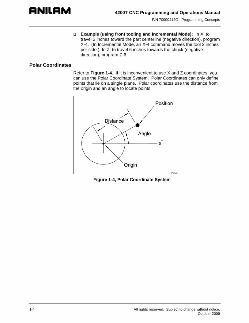
Polar Coordinates Refer to Figure 1-4. If it is inconvenient to use X and Z coordinates, you can use the Polar Coordinate System. Polar Coordinates can only define points that lie on a single plane. Polar coordinates use the distance from the origin and an angle to locate points.
POLAR Figure 1-4, Polar Coordinate System
1-4 All rights reserved. Subject to change without notice. October 2009

4200T CNC Programming and Operations Manual P/N 70000412G - Programming Concepts
Absolute Positioning Refer to Figure 1-5. When the CNC is in the Absolute Mode, all positions are measured from Absolute Zero. The Absolute Zero Reference, also called Part Zero, is not a fixed position on the machine; you select the point.
ABSOLUTE Figure 1-5, Absolute Positioning
You can set the Absolute Zero (X0, Z0) anywhere. Absolute Zero Reference is frequently at a position that makes it easy to use blueprint dimensions.
NOTE: In Absolute Mode, a move to X0, Z0 will move the machine to Absolute Zero.
All rights reserved. Subject to change without notice. 1-5 October 2009

4200T CNC Programming and Operations Manual P/N 70000412G - Programming Concepts
Incremental Positioning Refer to Figure 1-6. Incremental positions are measured from the machine’s current position. This is convenient for performing an operation at regularly spaced intervals.
INCREMEN Figure 1-6, Incremental Positioning
NOTE: If an Incremental command to X0, Z0 is programmed, the CNC remains at the current position.
Diameter or Radius Programming
NOTE: All program examples in this manual use Diameter Programming.
Refer to Figure 1-7, Diameter and Radius Programming. X Dimensions can be given in Diameter or Radius Mode:
Diameter X absolute dimensions are given as diameter values. X incremental dimensions are given as the diametric distance from the current diameter. X arc centers (I) are always given as actual distances.
Radius X absolute dimensions are given as radius values. X incremental dimensions are given as distance from the current position.
Since X0 is usually the centerline of the workpiece, diameter programming can simplify the programming of the workpiece.
1-6 All rights reserved. Subject to change without notice. October 2009

4200T CNC Programming and Operations Manual P/N 70000412G - Programming Concepts
R1R2R3
D1 D2 D3
DIARAD
R=RadiusD=Diameter
Figure 1-7, Diameter and Radius Programming
The default, set by the machine builder, is usually Diameter.
NOTE: In canned cycles (with the exception of area clearance), all X values are given as radial, regardless of whether diameter or radius programming is used.
Developing Part Programs The most important part of writing a CNC program is the planning. The following guidelines are provided to help a first-time programmer organize the process. First, decide how to hold the workpiece in the machine and where to set Part Zero. Part Zero is best located on the front face of the workpiece along the Z-axis and at the centerline of the workpiece in the X-axis. Try to select a Part Zero that facilitates the direct application of part print dimensions. Develop a program using a procedure similar to the one that follows: 1. To enter the Program Directory from the Manual screen, press
Program (F2). 2. Create a program name for the part by pressing Create (F2). 3. Enter the program name in the entry field for New Program.
Refer to “Section 10 - Program Management” for additional in-depth information.
4. Enter the Program Editor (press Edit (F8)) to open the new program and start writing blocks as described in steps 6 – 9 below. Refer to “Section 6 - Program Editor” for additional in-depth information.
5. The first block of any program is usually a safe start position and tool change position (a position away from the workpiece to which the axes can return for safe tool-changing). The first block is also normally used to state the units of measurement (Inch/MM), the mode of operation (Absolute), the move type (Rapid), and to cancel all auxiliary functions (Tool Offsets, Spindle, Coolant).
Typical first block: G70 G90 G0 X0 Z0 T0 M5
All rights reserved. Subject to change without notice. 1-7 October 2009

4200T CNC Programming and Operations Manual P/N 70000412G - Programming Concepts
1-8 All rights reserved. Subject to change without notice. October 2009
6. Subsequent blocks in the program set spindle information, call tool number, turn on coolant, etc., and make the initial move toward the workpiece.
7. The remaining blocks in the program describe the moves, canned cycles, and tool changes required to complete the machining of the workpiece.
8. The next to the last block in the program returns the axes to the tool change position, turning off any auxiliary functions (tool offsets, spindle and coolant). The last block is an M2 code that ends the program.
Typical final blocks: M5 G0 T0 X0 Y0 Z0 M2
9. Once you write a program, use Draw Graphics Mode to verify it. Make sure that correct machining procedures are being followed. Verify that all programmed moves are safe and accurate to the part print dimensions. Refer to “Section 8 - Draw Mode” for additional in-depth information.
10. At this point, you can load the stock material into the selected work-holding device.
11. Set the Tool Offsets for each tool in the Tool Page. Refer to “Section 9 - Tool Page and Tool Management” for additional in-depth information.
12. Prior to running the part in the Auto Mode, run it in Single Step to verify that both the program and the setting of tool offsets have been completed correctly. The Single Step Mode enables you to execute the program block by block.
13. After testing, the program is ready for production. Save the program on a floppy disk for future use. Refer to “Section 10 - Program Management” for additional in-depth information.

4200T CNC Programming and Operations Manual P/N 70000412G - CNC Console and Software Basics
Section 2 - CNC Console and Software Basics
CNC Console Refer to Figure 2-1. The CNC console consists of a 14-inch color screen and two keypads: one to the right of the screen and the other one underneath. Optionally, a 12.1-inch color flat panel console with a liquid crystal display (LCD) is available.
Monitor
Keypad
Softkeys
S s oft Key
Figure 2-1, CNC Console
All rights reserved. Subject to change without notice. 2-1 October 2009

4200T CNC Programming and Operations Manual P/N 70000412G - CNC Console and Software Basics
Keypad Refer to Figure 2-2. The keypad to the right of the monitor is laid out in two groups.
Alphanumeric Keys Editing Keys
Figure 2-2, Keypad Keys
2-2 All rights reserved. Subject to change without notice. October 2009

4200T CNC Programming and Operations Manual P/N 70000412G - CNC Console and Software Basics
Alphanumeric Keys Refer to Figure 2-2, Keypad Keys. Alphanumeric Keys enable you to key-in position coordinates (X and Z) and program G, M, S and T codes. Some keys contain two symbols or characters: a large character in the middle of the key and a smaller one in the upper left corner. The large characters are the primary characters. The small characters are the SHIFT characters. To type a primary character, press the key that displays that character. To type a SHIFT character, do the following: 1. Press SHIFT. 2. Press the key that displays the character in the upper left corner. Refer to Table 2-1. Primary functions and SHIFT Key functions are listed.
Table 2-1, Alphanumeric Keys
Key Face Primary Function Shift Function
Letter A None
Letter B Less Than Symbol
Letter C Greater Than Symbol
Letter D Caret
Letter E None
Letter F/Feed rate Left Bracket
Letter G/G Codes Right Bracket
Letter H Exclamation Point
Letter I None
Letter J Apostrophe
Letter K Tilde Symbol
Letter L “At” Symbol
Letter M/Miscellaneous Functions
None
Letter N Left Curly Bracket
Letter O/Program Number Designator
Right Curly Bracket
Letter P Dollar Sign
Letter Q None
All rights reserved. Subject to change without notice. 2-3 October 2009

4200T CNC Programming and Operations Manual P/N 70000412G - CNC Console and Software Basics
2-4 All rights reserved. Subject to change without notice. October 2009
Key Primary Function Shift Function Face
Letter R Underscore
Letter S/Spindle Speed Designator
Backslash
Letter T/Tool words Single Quote
Letter U None
Letter V Question Mark
Letter W Colon
Letter X/X Axis Coordinate None
Letter Y None
Letter Z/Z Axis Coordinate None
Number one Left Parenthesis
Number two Right Parenthesis
Number three Pound or Number Sign
Number four Vertical Bar; Used To Separate
Parts Of A Blueprint Programming Block For Angles/Chamfers/Radii.
Number five Semi-Colon
Number six Slash
Number seven Ampersand
Number eight Percent Symbol
Number nine Inch Symbol
Number 0 Equal Sign
Minus sign/dash Plus Sign
Period/Decimal sign Asterisk: Used To “Comment
Out” All Or Part Of A Block (Any Characters To The Right Of The Asterisk Are Ignored). The CNC Ignores These Blocks.

4200T CNC Programming and Operations Manual P/N 70000412G - CNC Console and Software Basics
Editing Keys Refer to Table 2-2. Use the editing keys to edit programs and move around the screen.
Table 2-2, Editing Keys
Label or Name
Key Face Purpose
CLEAR
Clears messages, values, commands and program blocks that you select.
ARROW
Allows you to move highlight bars and cursor around the screen.
ENTER
Selects blocks for editing; activates menu selections; activates number entry.
SHIFT
Selects the SHIFT characters on the keypad. Remains ON until the next key is pressed.
SPACE
Types a space at the cursor.
Using the Keypad to Program Moves Refer to Table 2-3. These keys appear on the keypad in pale yellow or white. They are the main keys used to program moves, positions and other commands.
Table 2-3, Programming Word Keys
Label or Name Key Face Function G-CODES
Program G-codes.
MISCELLANEOUS FUNCTIONS
Activate Miscellaneous Functions.
X AXIS COORDINATE
Indicates X Axis position.
Z AXIS COORDINATE
Indicates Z Axis position.
SPINDLE SPEED
Provides Spindle Speed or provides maximum speed in a Constant Surface Speed move.
TOOL WORDS
Activates a tool and associated offsets.
(Continued…)
All rights reserved. Subject to change without notice. 2-5 October 2009

4200T CNC Programming and Operations Manual P/N 70000412G - CNC Console and Software Basics
Table 2-3, Programming Word Keys (Continued)
Label or Name Key Face Function POSITIVE/NEGATIVE INDICATOR
Used to indicate positive or negative direction or value, plus or minus; in Manual Data Input (MDI) mode, press key to insert a minus (-) sign.
DECIMAL/ASTERISK
Decimal (.): In Manual Mode, marks decimal place in coordinates. Asterisk (*): Use to “comment out” all or part of a block (characters to the right of the asterisk will be ignored). NOTE: To type an asterisk,
press SHIFT + .
Soft Keys The soft keys (also called function keys) are located on a keypad just below the screen. They are labeled F1 through F10. Soft key functions are not hardwired. Their functions change with changes in mode. The current function of each soft key appears on the screen in a label directly above each key. If a soft key label is blank, the soft key has no active function.
Accessing Keypad Commands Using a PC Keyboard (Optional) The CNC supports an optional external keyboard. Most standard PC computer keyboards are compatible. All alphanumeric keypad keys are available by pressing the corresponding key on the PC keyboard.
Software Basics The CNC’s screens change as different modes are activated. The basic procedures and features of the software remain the same, regardless of the mode of the CNC.
2-6 All rights reserved. Subject to change without notice. October 2009

4200T CNC Programming and Operations Manual P/N 70000412G - CNC Console and Software Basics
Pop-up Menus Refer to Figure 2-3. Pop-up menus are temporary menus that enable you to make additional selections. Pop-up menus automatically appear where needed. Each pop-up menu contains a highlight bar. Use the ARROW keys to move the highlight bar up and down the menu. To activate a highlighted selection, press ENTER. To close a pop-up menu, press the key that activated it or press CLEAR.
Pop-Up Menu
Figure 2-3, Pop-Up Menus
Screen Saver After a set period of inactivity, the CNC’s screen dims to preserve the monitor. Press any key to restore the CNC to a ready status. Keystrokes are not recognized until after you reactivate the monitor.
Highlight Bars Each menu screen is equipped with a highlight bar. The highlight bar enables you to choose one of the selections. To move the highlight bar up, down, left, or right, press the appropriate ARROW key. Press ENTER to activate the highlighted selection.
Cursors Some screens use a white underscore to indicate where to insert numbers and letters.
Clearing Entries Press CLEAR key to delete all portions of an entry.
Operator Prompts The CNC displays a prompt when it requires specific information. When the CNC prompts for a text entry, enter the information required to complete the operation.
All rights reserved. Subject to change without notice. 2-7 October 2009

4200T CNC Programming and Operations Manual P/N 70000412G - CNC Console and Software Basics
2-8 All rights reserved. Subject to change without notice. October 2009
Typeover and Insert Modes The edit mode has two text entry modes: “typeover” and “insert”. By default, the CNC runs in the typeover mode. In the typeover mode, new characters replace characters marked by the cursor (the white underline). In Ins (F3) mode, new characters appear at the cursor and existing characters move to the right. The Ins (F3) soft key label highlights when the CNC is in “insert” mode. To put the CNC in the Insert Mode:
1. Go to the Edit screen.
2. In Edit Mode, press Ins (F3). The Ins soft key label highlights, indicating that Insert Mode is ON.
Deleting Text To delete text:
1. Go to the Edit screen.
2. In edit mode, press Del (F2). The character to the right of the cursor is then deleted.
Messages/Error Messages Messages generated by the CNC are displayed in the MESSAGE area of the screen. It appears in all operating modes (S. Step, Auto, and Manual). When the CNC generates more than one message, the message with the highest priority is displayed in the MESSAGE area. Lower priority messages remain in memory. The MESSAGE label is highlighted while messages are stored in memory. There are two ways to review pending messages:
Press CLEAR key. The current message clears and the next message appears.
Go to the Manual screen and press SHIFT + Message (F1). The Message Screen activates.
Refer to Figure 2-4, Message Window. The MESSAGE screen enables you to view the last eight messages, whether or not they have been displayed. As new messages are generated, the oldest messages are cleared. Messages that have not been displayed appear at the top of the MESSAGE screen. Old messages appear below. To close the MESSAGE screen, press Cont (F10). To clear stored messages, close the MESSAGE screen and press CLEAR until the MESSAGE highlight clears. Some messages are advisory in nature, others put the CNC in hold. If an error holds the CNC, solve the problem before you restart the program.

4200T CNC P/N 70000412
Programming and Operations Manual G - CNC Console and Software Basics
Old Messages
Figure 2-4, Message Window
All rights reserved. Subject to change without notice. 2-9 October 2009


4200T CNC Programming and Operations Manual P/N 70000412G - Manual Operation and Machine Setup
Section 3 - Manual Operation and Machine Setup This section describes the functions of the keys and switches on the Manual Panel. It also provides information on manual operations.
Manual Panel Refer to Figure 3-1. The Manual Panel contains the Manual Operation keys. Use these keys to move the machine manually.
All rights reserved. Subject to change without notice. 3-1 October 2009
NOTE: Some machines have the handwheels mounted to the machine tool. On these types of lathes, the handwheel shown on the manual panel is omitted.
Figure 3-1, Manual Panel

4200T CNC Programming and Operations Manual P/N 70000412G - Manual Operation and Machine Setup
Manual Panel Keys Manual Operation Keys enable you to control machine movements manually. These keys are located on the Manual Panel. See Table 3-1.
Table 3-1, Manual Operation Keys
Label or Name Key Face Purpose JOG
Cycles the CNC through manual movement modes (JOG: RAPID, JOG: FEED, JOG: 100, JOG: 10, JOG: 1). The machine builder sets the default rapid and feed rates at setup and determines the actual speed of the machine during a move.
AXIS SELECT
In Manual Mode, selects the axis to be jogged.
SPINDLE OVERRIDE
Overrides the programmed spindle RPM rate. It is a 13-position rotary switch that ranges from 40 to 160 percent. (Each increment adjusts the spindle override by 10%.) This feature can be used only on machines with programmable spindles.
FEEDRATE OVERRIDE
Overrides the feed and/or rapid rate of the axes in Manual, Auto, and Single Step modes. It is a 13-position rotary switch, which ranges from 0 to 120 percent. (Each increment adjusts the feedback override by 10%.)
NOTE: The override range for rapid rate is 100%. The CNC will not exceed the maximum rapid rate.
HANDWHEEL (optional)
Moves selected controlled axis while in the Manual Mode. Jog must be set to 1, 10, or 100.
SERVO RESET
Activates servo motors.
SPINDLE FORWARD
Starts spindle in a forward direction. NOTE: On some machines, gear range and RPM
may need to be specified before you activate this key.
SPINDLE REVERSE
Starts spindle in a reverse direction. NOTE: On some machines, gear range and RPM
may need to be specified before you activate this key.
SPINDLE OFF
Stops the spindle.
START
Starts all machine moves, except Jog.
SPINDLE
(Continued…)
3-2 All rights reserved. Subject to change without notice. October 2009

4200T CNC Programming and Operations Manual P/N 70000412G - Manual Operation and Machine Setup
Table 3-1, Manual Operation Keys (Continued)
Label or Name Key Face Purpose JOG +
Moves selected axis in positive direction. Used in all Jog modes. Feedrate determined by machine builder.
JOG -
Moves selected axis in negative direction. Used in all Jog modes. Feedrate determined by machine builder.
HOLD
Halts any running program or programmed move. Press START to continue.
EMERGENCY STOP (E-STOP)
The Emergency Stop button is bright red with white arrows. Press E-STOP to halt all axes and machine-related functions. When E-STOP is activated, the servo motors and any programming operations are shut down. The CNC defaults to Manual Mode. Use E-STOP for emergency shutdowns or to shut down the servos intentionally.
Manual Panel LEDs The following keys have LEDs located directly above them on the Manual Panel. When the key is activated, the corresponding LED lights up.
Servo Reset Spindle Off Spindle Forward Spindle Reverse
Refer to Figure 3-1, Manual Panel. The Coolant Ready LED is also located on the Manual Panel. Some CNCs are equipped with a Coolant Ready M-function. For these CNCs, the Coolant Ready LED lights when the coolant is ready. The coolant is programmed to come ON when the machine receives a SPINDLE ON command.
All rights reserved. Subject to change without notice. 3-3 October 2009

4200T CNC Programming and Operations Manual P/N 70000412G - Manual Operation and Machine Setup
Manual Mode Screen Refer to Figure 3-2. When the CNC is in Manual Mode, it displays the Manual screen. The Manual screen is the first screen displayed when you turn on the CNC. All other operating screens are similar in appearance and are selected from the Manual screen soft keys. In Manual Mode, the Manual (F4) soft key label highlights.
Program Area
Command Line
Message Line
Machine Position Display
Program Position DisplayTarget Position DisplayDistance to Go PositionDisplay
Machine StatusDisplay Area
Active Softkey(highlights)
Active Soft Key ( ) highlighted
Figure 3-2, Manual Screen
The Manual screen is divided into the following areas: Program Area Displays the storage device access indicator, the
working program name, running status, mode of operation, and in-position status.
Command Line Enables you to enter commands manually. Message Line Displays messages, prompts, and reminders.
Machine Position Display Displays machine’s X and Z position coordinates in
reference to Machine Home.
Program Position Display Displays machine’s X and Z position coordinates in
reference to Program. Target Position Display Displays machine’s X and/or Z programmed target
position.
3-4 All rights reserved. Subject to change without notice. October 2009

4200T CNC Programming and Operations Manual P/N 70000412G - Manual Operation and Machine Setup
All rights reserved. Subject to change without notice. 3-5 October 2009
Distance To Go Displays distance to go with respect to X and Z commanded coordinates.
Machine Status Display Area Displays operating information.
Active Soft Key Refer to Table 3-2. Soft key functions change from screen to screen. An active function identifies the function of the soft key. A highlighted label indicates an active mode.
Table 3-2, Manual Mode Soft Keys
Soft Key Name Soft Key Number
Description
Help F1 Help Mode activates. Program F2 List of user programs. Edit F3 Edit Mode activates. A program
must first be selected. Manual F4 Press to enter Manual Mode from
Auto and S.Step. S.Step F5 Changes to Single Step Mode Auto F6 Changes to Auto Mode. Use to
run part programs for production.
Delete F7 Deletes a character from the command line in Manual Mode.
Insert F8 Puts the cursor in Insert Mode. Typed text is inserted without overwriting existing text.
Tool F9 Brings Screen to the Tool Page. Tool Page is used to store tool diameter and length offsets, and wear factors.
Machine Status Display Area Labels
TOOL: Active tool.
DIA: Active tool radius. XOFF: X-axis tool length offset for active tool.
RPM: Current spindle speed in revolutions per minute.
FEED: Current feed rate (in Inch/MM per minute).
ZOFF: Z-axis tool length offset for active tool.
% (RPM): Spindle override setting (40% to 160%).
% (FEED): Feedrate override setting (0% to 120% for Feed moves and 0% to 100% for Rapid moves).
LOOP: Loop counter. Counts down the number of times a loop command has been performed.

4200T CNC Programming and Operations Manual P/N 70000412G - Manual Operation and Machine Setup
3-6 All rights reserved. Subject to change without notice. October 2009
DWELL: A timed pause, indicated in number of seconds or revolutions. Units are specified as seconds or revolutions, during builder setup.
OVERRIDE: Indicates whether the feedrate override setting applies to both feed and rapid moves or to feed moves only.
OFFSET: Active G53 offset.
PARTS: Number of parts. Resets to zero when you enter Auto or Single Step mode.
TIMER: Indicates amount of time per part and accumulated amount of time (in parentheses) for all parts. Resets to zero when you enter Auto or Single Step mode.
G: Active G-codes.
M: Active M-codes.
Program Area Labels BLK: Block number (in S. Step or Auto Mode).
PROGRAM: Name of loaded program.
HALTED/*HALTED: No asterisk: Indicates machine is in a programmed hold or has completed its program.
With asterisk: Indicates hold was activated by an event or HOLD was pressed.
MANUAL/AUTO/S.STEP: Current operating mode displayed.
IN-POSN: Indicates whether the machine has reached an endpoint (in-posn).
COMMAND: Used to enter commands in Manual Mode.
Powering on the CNC Refer to Figure 3-1, Manual Panel. The E-STOP can be in or out when powering up. Turn ON the CNC according to the builder’s instructions. When the switch is ON, the CNC completely resets. All parameters and variables reset to their default values. To power on the CNC: 1. Turn the power switch ON. The startup screen activates and prompts
you to “Press F10 to continue”. 2. Press F10. The CNC displays the Software Options menu. 3. Highlight Control Software, and press ENTER. Manual Mode
activates.

4200T CNC Programming and Operations Manual P/N 70000412G - Manual Operation and Machine Setup
All rights reserved. Subject to change without notice. 3-7 October 2009
Shutting Down the CNC To shut down the CNC: 1. Press E-STOP. The servos disengage and the CNC reverts to Manual
Mode. 2. Press SHIFT (F10). The CNC displays the Software Options menu. 3. Follow the builder’s instructions for turning the CNC OFF.
Setting/Resetting the Emergency Stop (E-STOP) 1. Press E-STOP to take all axes and spindle servos offline and halt all
machine movement. 2. To reset the E-STOP, pull out the E-STOP rotary switch and rotate it
clockwise in the direction of the arrows. The switch makes a clicking sound when it resets. Resetting the E-STOP does not automatically reactivate the servos. The servos must be reset to move the machine.
3. Press SERVO RESET to reset the servos.
Activating/Resetting the Servos For safety reasons, the CNC powers up with the servo motors disengaged. While the servos are off, the CNC cannot move the machine. A “SERVO OFF!” message is generated when the servos are disengaged. The servos are also disengaged when you press E-STOP, or if the machine attempts to move beyond a limit switch. To reset the servos: 1. If the servos were disengaged by a limit switch, manually reposition
the machine inside its normal range of travel. 2. Press E-STOP. “MESSAGE: E-STOP IN - SERVO OFF!” is displayed
in the MESSAGE area. 3. Reset the E-STOP by rotating the E E-STOP rotary switch in the
direction of the arrows. The switch makes a clicking sound when it resets.
4. Press SERVO RESET. “MESSAGE: SERVO DELAY, PLEASE WAIT…” is displayed while the servos are being reset. The message disappears when the servos reset.
Manual Mode Settings Features (or settings) that remain active for more than one operation are said to be “modal”. Modal features remain active until changed or canceled. The CNC’s function is modal. For example, when in Rapid Mode, the CNC executes all moves in Rapid until put in the Feed Mode. The CNC can be in two modes, such as the Absolute Mode and the Inch Mode, at the same time, as long as the modes do not conflict.

4200T CNC Programming and Operations Manual P/N 70000412G - Manual Operation and Machine Setup
3-8 All rights reserved. Subject to change without notice. October 2009
Before you make a manual move, make any necessary mode settings. Modes set from the Manual screen remain active if the CNC is put in a program operating mode until the mode is changed by the program or operator.
The following modes can be set from the Manual screen: Position mode: either Absolute or Incremental Positioning. Move mode: (Rapid or Feed) – for either Rapid move or a move at a
specified feedrate. The active tool (includes tool length offsets and tool nose radius
compensation). The measurement mode (Inch/MM).
The following settings can be made in the Manual screen: The location of Machine Home position. The location of Part Zero.
There are three types of moves available in Manual Mode: Jog (Conventional) Jog (Continuous) Manual Data Input (MDI)
Activating Manual Mode Rapid or Feed Turn the JOG rotary switch to cycle through all available jog modes. Choose Rapid or Feed Mode. The active feedrate/rapid mode is displayed in the Machine Status Display Area.
NOTE: In Manual Mode, press R + ENTER to toggle the override setting between the following choices:
o FEED and RAPID rate override (FEED, RAPID)
o FEEDRATE override (FEED)
Switch the setting to apply the current override selection to programmed rates.
Adjusting the Feedrate
NOTE: If G95 (feedrate per revolution) is used, the spindle must be turning. Otherwise, the axes cannot be moved.
The basic feedrate is manually keyed in as Feedrate Per Minute (FPM, G94) or Feedrate Per Revolution (FPR, G95) command. You can change the feedrate at any time, manually or in a program. Use F-codes to set the feedrate. The F-code follows the G94 or G95 command in the following format:
G94 Fnnn or G95 Fnnn Refer to “Section 4 - Preparatory Functions: G-Codes” for details pertaining to G-codes.

4200T CNC Programming and Operations Manual P/N 70000412G - Manual Operation and Machine Setup
All rights reserved. Subject to change without notice. 3-9 October 2009
When the FEEDRATE OVERRIDE is set to 100%, the CNC makes all Feed moves at the programmed feedrate. To run the CNC at a percentage of the programmed feedrate, adjust the FEEDRATE OVERRIDE. Each click of the FEEDRATE OVERRIDE adjusts the feedrate setting by increments of 10% each. The override rotary switch has a range of 0% to 120%. Align the rotary switch pointer with the white stripe to set the override to 100%. All moves are affected by the FEEDRATE OVERRIDE.
CAUTION: When the CNC is shut down, the manufacturer’s setup file will reload a default feedrate when it powers up again.
Adjusting Rapid Move Speed The FEEDRATE OVERRIDE also adjusts Rapid moves. If FEED, RAPID is set, every click of the FEEDRATE OVERRIDE adjusts the Rapid rates by increments of 10% of the default speed. The override rotary switch gives you a range of 0% to 100%. Align the rotary switch pointer with the white stripe to set the override to 100%. The maximum override rate for rapid speeds is 100%.
NOTE: the machine builder at setup determines the default rapid rate.
NOTE: In Manual Mode, press R + ENTER to toggle the override setting between the following choices:
o FEED and RAPID rate override (FEED, RAPID)
o FEEDRATE override (FEED)
Toggle the setting to apply the current override selection to programmed rates.

4200T CNC Programming and Operations Manual P/N 70000412G - Manual Operation and Machine Setup
Setting Absolute Zero Refer to Figure 3-3. In Absolute Mode, all positions are measured from Absolute Zero. Absolute Zero is the point the CNC recognizes as X0, Z0 when the Absolute Positioning Mode is active. You can set Absolute Zero anywhere within or outside a machine’s range of travel. It can be moved as many times as necessary. All absolute X and Z positions are measured from this point. Setting the Absolute Zero Reference to a location on the part is referred to as “setting the Part Zero”.
ABSOLUTE Figure 3-3, Absolute Positioning
Part Zero In all programming examples in this manual place, Part Zero is the centerline (X) and front face (Z) of the part. There are three ways to establish Part Zero on a workpiece for a particular tool:
Tool length offsets (TLO) G53 offsets Absolute Presets (G92)
TLOs (T-codes) are the best way to set Part Zero. Tool length offsets enable you to program the moves from Part Zero, regardless of the type or size of the tool. Enter tool length offsets into the Tool Page; then, activate as needed. Refer to “Section 9 - Tool Page and Tool Management” for details on how to use tool length offsets to set Part Zero. G53 offsets are used to change Zero location. G92 absolute presets make the current position set to what you enter, i.e., the X, Z entry becomes the current position when G92 is entered.
3-10 All rights reserved. Subject to change without notice. October 2009

4200T CNC Programming and Operations Manual P/N 70000412G - Manual Operation and Machine Setup
All rights reserved. Subject to change without notice. 3-11 October 2009
When the machine is powered up, its present location is automatically set as the Absolute Zero Reference. When the CNC is shut down, the position of the Absolute Zero Reference is lost.
Jog Moves Jog moves are available in Manual Mode, Teach Mode, or when the Tool Page is active and the servos are on. Refer to Table 3-3. There are five available jog modes. The actual rate for each mode is determined at machine setup. Use JOG to cycle the CNC through the jog mode choices.
NOTE: You can change the Jog Mode at any time when the CNC is in Manual Mode.
Table 3-3, Jog Moves
Mode Description Rapid Default rapid speed for continuous jogs. Actual speed
determined at machine setup. Feed Continuous jog at feedrate determined at machine
setup. Jog: 100 Conventional Jog Mode. Increment set to 100 times
resolution of machine. Jog: 10 Conventional Jog Mode. Increment set to 10 times
resolution of machine. Jog: 1 Conventional Jog Mode. Increment set to actual
resolution of machine.
Changing the Jog Mode Jog moves, with the exception of Rapid, are performed in Feed. To change the Jog Mode: 1. In Manual Mode, turn the JOG rotary switch to select a jog feedrate.
NOTE: You can change the Jog Mode in Manual Mode, Teach Mode, or when the Tool Page is active.
Selecting an Axis To select an axis in the Manual Mode: 1. Turn AXIS SELECT rotary switch to cycle through the available axes.
Turn the switch until the indicator points to the desired axis.

4200T CNC Programming and Operations Manual P/N 70000412G - Manual Operation and Machine Setup
3-12 All rights reserved. Subject to change without notice. October 2009
Jogging the Machine (in Increments) In Manual Mode, you can position the machine with jog increments. Jog increments advance the machine in selected increments: 1, 10, or 100 times the machine resolution. To make a jog increment move: 1. Use the AXIS SELECT rotary switch to select an axis. 2. Use the JOG switch to cycle through the move mode choices and
choose a conventional Jog Mode (1, 10 or 100 times machine resolution).
3. Press the JOG+ or JOG- key to choose a direction. Do not hold down the key. Each time you press the key, the machine jogs along the selected axis by the selected increment.
Jogging the Machine (Continuous Moves) In Manual Mode, you can move the machine at feed rate or at the jog rapid rate. The machine builder determines the effective jog and feed rates at setup. 1. In Manual screen active, use the AXIS SELECT rotary switch to select
an axis. 2. Using the JOG switch, choose a continuous jog mode (Feed or Rapid). 3. Press and hold down the JOG+ or JOG- key to jog the machine in the
desired direction. The machine jogs along the selected axis. To stop the machine, release the key.
Manual Data Input (MDI) Mode
NOTE: In MDI mode, you cannot execute canned cycles or activate Tool Nose Radius Compensation.
The Manual Data Input mode (MDI) enables you to command moves without creating a part program. MDI is also a quick way to program a single move, or a series of moves that will be used only once.
To execute commands, type an instruction on the COMMAND: line of the Program Area and press the START key. In Manual Mode, the cursor rests on the command line.
You can program more than one command at a time. Use a block separator (;) to separate the commands.
One shot moves can be paused by pressing HOLD, continued by pressing START, or canceled altogether by pressing MANUAL (F4). MDI moves are executed only once. To recall a previously commanded block, press the press UP ARROW key as many times as necessary. Approximately 2K (2048) bytes of MDI commands are stored in memory and can be recalled by using Up (Previous) and Down (Next) arrow keys.
CAUTION: It is important that you know where the Absolute Zero is before you make Absolute Mode moves.

4200T CNC Programming and Operations Manual P/N 70000412G - Manual Operation and Machine Setup
All rights reserved. Subject to change without notice. 3-13 October 2009
Using Manual Data Input Mode To use Manual Data Input Mode: 1. In Manual Mode, type the command block(s) at the COMMAND: line. 2. Press START. The CNC will execute the typed commands. Most functions that can be commanded in a part program can also be commanded in MDI Mode. These include:
G00, G01, G02, G03 moves M-codes, T-codes (tool activation), S-codes (spindle speed) Modal commands (G90, G91, G70, G71, etc.) G-codes (G92, G28, G53, etc.)
The following example demonstrates how MDI Mode might be used to activate the spindle: COMMAND: M43; G97 S600; M3 M43 Activates Gear Range defined by M43 in setup G97 S600 Actives specified Spindle Speed M3 Activates Spindle Forward
Handwheel Operation
NOTE: The manual panel can include an optional handwheel. This handwheel is omitted if a customer has elected to purchase one or more handwheels mounted to the machine.
The sub-sections below describe handwheel operation for: Standard handwheel configuration, consisting of one handwheel
mounted on the manual panel. Purchased option, consisting of one or two handwheels mounted on
the machine.
Operating a Handwheel Mounted on the Manual Panel In some 4200T systems, one handwheel is mounted on the Manual Panel. In Manual Mode, you can use the handwheel to jog any controlled axis (X or Z). The machine builder must enable the handwheel option in the Setup Utility.
NOTE: The handwheel soft key (F10) is labeled “HandWl”. If the Handwheel feature has not been enabled in the Setup Utility, the F10 soft key will not be labeled “HandWl”.
To operate the standard handwheel: 1. In Manual Mode, press HandWl (F10). The HandWl (F10) soft key
activates and highlights. 2. Use AXIS SELECT to select an axis. 3. Use the JOG to select a conventional Jog Mode (1, 10 or 100). 4. Rotate the handwheel in a positive or negative direction. 5. To return to the Manual Mode, press HandWl (F10). The handwheel
option deactivates and the soft key is no longer highlighted.

4200T CNC Programming and Operations Manual P/N 70000412G - Manual Operation and Machine Setup
3-14 All rights reserved. Subject to change without notice. October 2009
Refer to Table 3-4 for JOG selections available with the handwheel.
Table 3-4, Handwheel Jog Resolution Settings
Jog Mode Setting Handwheel Resolution FEED Not Available RAPID Not Available 1 Machine Resolution 10 10 times Machine Resolution 100 20 times Machine Resolution
Operating Handwheels Mounted on the Machine As a purchased option, two handwheels can be mounted on the machine, one for each axis (X and Z). The handwheel is mounted so that it directly controls axis movement. While in the Manual Mode, you can use the handwheels to jog the X and Z-axis. The machine builder must enable the handwheel feature in the Setup Utility. Refer to Table 3-4 for JOG selections available with the handwheel option. To operate a Handwheel mounted on the machine: 1. Use JOG to select a conventional jog mode (1, 10 or 100). 2. Rotate the handwheel in a positive or negative direction.

4200T CNC Programming and Operations Manual P/N 70000412G - Preparatory Functions: G-Codes
All rights reserved. Subject to change without notice. 4-1 October 2009
Section 4 - Preparatory Functions: G-Codes
Preparatory Functions: G-Codes G-codes initiate motion commands, canned cycles, various machine functions and other CNC capabilities. More than one G-code may be specified per block. If a block contains conflicting G-codes, an error message appears. Refer to Table 4-1, Modal and Non-Modal G-Codes for a list of modal and non-modal G-codes. Modal G-codes remain in effect until canceled by the appropriate code. Non-modal G-codes affect only the block in which they are programmed. Once the non-modal block is completed, the Modes active before the non-modal command take effect again. Non-modal G-codes have no preset defaults. In the subsections that describe individual G-codes, every attempt has been made to show the most convenient method of programming each code. There are usually several ways to program a G-code. Typically, if a move type or G-code is covered in the Edit Help Menus or Edit Help G-Code Menu, you should use these sources to program the code. In all cases, you can program G-codes in the Edit Mode.

4200T CNC Programming and Operations Manual P/N 70000412G - Preparatory Functions: G-Codes
4-2 All rights reserved. Subject to change without notice. October 2009
Table 4-1, Modal and Non-Modal G-Codes
Modal Non-Modal G-Code Function G-Code Function G0 Positioning-Rapid Traverse G4 Dwell G1 Linear Interpolation G5 Ellipse G2 Circular Interpolation-CW G9 Exact Stop Check G3 Circular Interpolation-CCW G31 Probe Move G22 Stored Stroke Limit ON
(Programmable Stroke Limit) G33 Threading
G24 Spindle Speed Clamp G65 User Macro Single Call G40 Tool Tip Radius Compensation,
Cancel G74 Area Clearance (Face) Cycle
G41 Tool Tip Radius Compensation, Left of Path
G76 Rough Turning/Boring Cycle
G42 Tool Tip Radius Compensation, Right of Path
G77 Rough Facing Cycle
G53 Work Coordinate System (1-99, select)
G78 Peck Drill Cycle
G59 Modal Corner Rounding G79 Chip Break Drill Cycle G60 Modal Corner Rounding Off G81 Longitudinal Grooving Cycle
(Turn) G61 Exact Stop Check Mode
(Continuous Path OFF) G82 Face Grooving Cycle
G64 Cutting Mode (Continuous Path ON)
G83 Longitudinal Thread Cycle, Plunge
G66 User Macro Modal Call G84 Longitudinal Thread Cycle, Compound
G67 User Macro Modal Call Cancel G85 Face Thread Cycle, Plunge G68 Coordinate System Rotation G86 Face Thread Cycle, Compound G70 Inch Programming G87 Tapping Cycle G71 MM Programming G88 Boring G72 Axis Scaling G92 Absolute Zero Preset G90 Absolute Programming G91 Incremental Programming G94 Per Minute Feed G95 Per Revolution Feed G96 Constant Surface Speed
Function (CSS)
G97 Revolutions Per Minute (RPM)
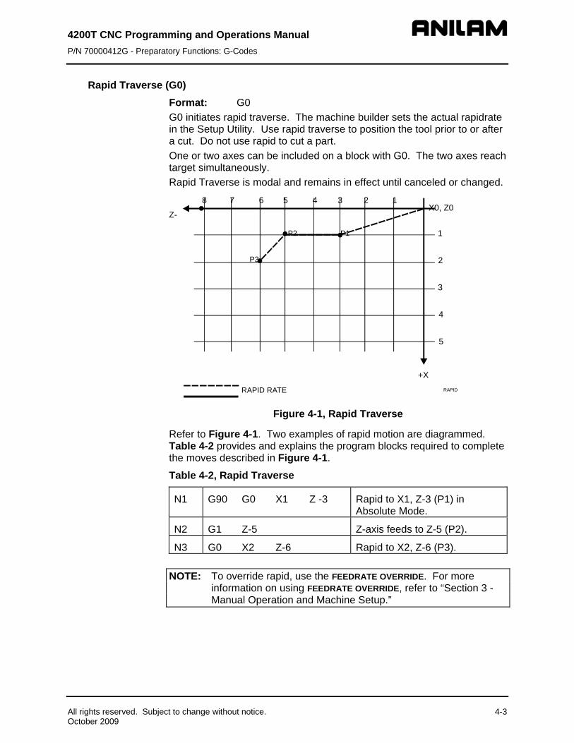
4200T CNC Programming and Operations Manual P/N 70000412G - Preparatory Functions: G-Codes
Rapid Traverse (G0) Format: G0 G0 initiates rapid traverse. The machine builder sets the actual rapidrate in the Setup Utility. Use rapid traverse to position the tool prior to or after a cut. Do not use rapid to cut a part. One or two axes can be included on a block with G0. The two axes reach target simultaneously. Rapid Traverse is modal and remains in effect until canceled or changed.
5
4
3
2
1
1235678X0, Z0
4
P1P2
P3
All rights reserved. Subject to change without notice. 4-3 October 2009
RAPIDRAPID RATEFEED RATE
+X
Z-
Figure 4-1, Rapid Traverse
Refer to Figure 4-1. Two examples of rapid motion are diagrammed. Table 4-2 provides and explains the program blocks required to complete the moves described in Figure 4-1.
Table 4-2, Rapid Traverse
N1 G90 G0 X1 Z -3 Rapid to X1, Z-3 (P1) in Absolute Mode.
N2 G1 Z-5 Z-axis feeds to Z-5 (P2).
N3 G0 X2 Z-6 Rapid to X2, Z-6 (P3).
NOTE: To override rapid, use the FEEDRATE OVERRIDE. For more information on using FEEDRATE OVERRIDE, refer to “Section 3 - Manual Operation and Machine Setup.”

4200T CNC Programming and Operations Manual P/N 70000412G - Preparatory Functions: G-Codes
Linear Interpolation (G1) Format: G1
Linear Interpolation (G1) initiates feed motion in a straight line. It is used for cutting a part. Straight-line motion can be linear or angular. The block could contain any combination of the available axes.
G1 is modal and remains in effect until changed. A feedrate must be given on or prior to the G1 block.
Linear moves require only one dimension to define the endpoint of motion. Provide the dimension (X or Z) for the axis in which motion occurs. Table 4-3 demonstrates how G1 is used in a program to perform linear moves. MM equivalents are provided in parentheses following the Inch measurements. Figure 4-2 is a diagram of the part programmed.
Table 4-3, Straight Line Programming, Absolute/Inch (MM) Mode
N1 G90 G70 (G71) G1 X0 Z0 G95 F.010 (.25)
Feed to P1.
N2 X1 (25.4) Feed from P1 to P2.
N3 Z-1.5 (-38.1) Feed from P2 to P3.
N4 X2 (50) Feed from P3 to P4.
N5 Z-4.25 (-107.95) Feed from P4 to P5.
N6 X3 (76.2) Feed from P5 to P6.
N7 M2 End program, return to N1.
Figure 4-2, Linear Motion
4-4 All rights reserved. Subject to change without notice. October 2009
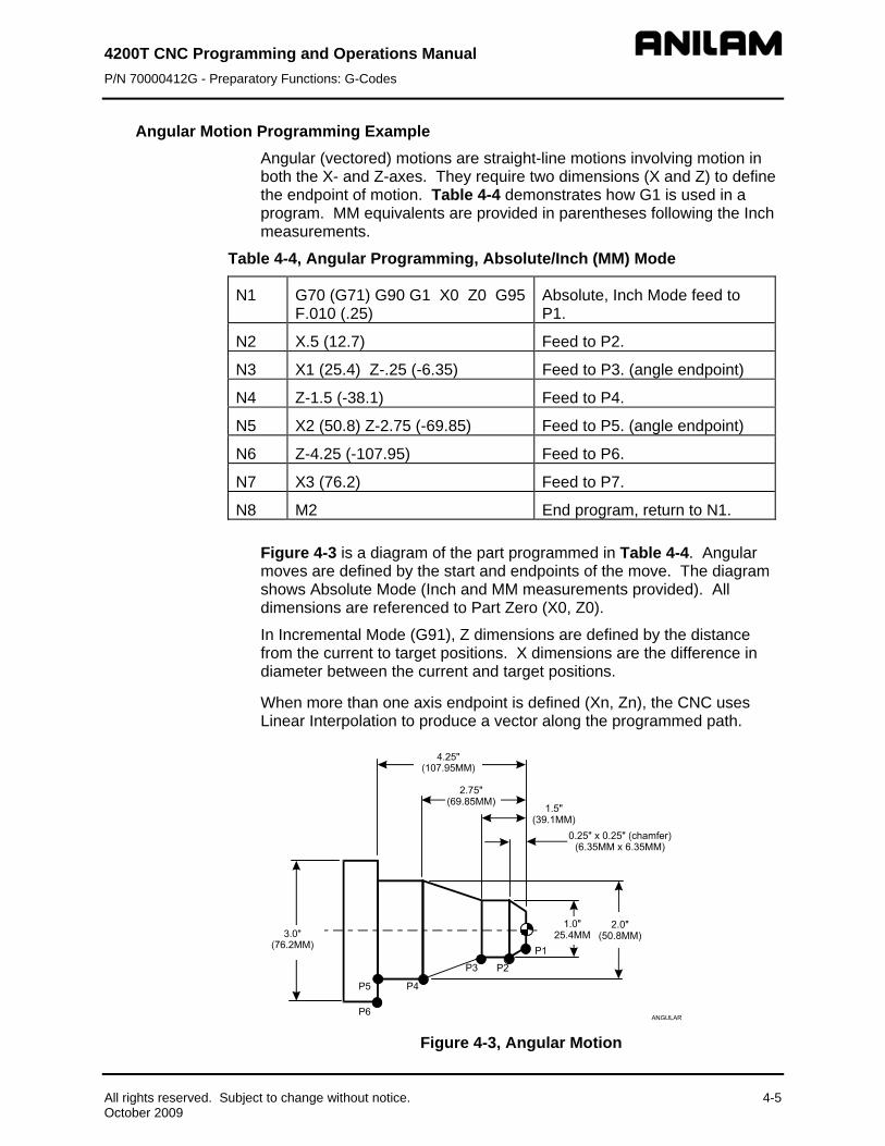
4200T CNC Programming and Operations Manual P/N 70000412G - Preparatory Functions: G-Codes
Angular Motion Programming Example Angular (vectored) motions are straight-line motions involving motion in both the X- and Z-axes. They require two dimensions (X and Z) to define the endpoint of motion. Table 4-4 demonstrates how G1 is used in a program. MM equivalents are provided in parentheses following the Inch measurements.
Table 4-4, Angular Programming, Absolute/Inch (MM) Mode
N1 G70 (G71) G90 G1 X0 Z0 G95 F.010 (.25)
Absolute, Inch Mode feed to P1.
N2 X.5 (12.7) Feed to P2.
N3 X1 (25.4) Z-.25 (-6.35) Feed to P3. (angle endpoint)
N4 Z-1.5 (-38.1) Feed to P4.
N5 X2 (50.8) Z-2.75 (-69.85) Feed to P5. (angle endpoint)
N6 Z-4.25 (-107.95) Feed to P6.
N7 X3 (76.2) Feed to P7.
N8 M2 End program, return to N1.
Figure 4-3 is a diagram of the part programmed in Table 4-4. Angular moves are defined by the start and endpoints of the move. The diagram shows Absolute Mode (Inch and MM measurements provided). All dimensions are referenced to Part Zero (X0, Z0).
In Incremental Mode (G91), Z dimensions are defined by the distance from the current to target positions. X dimensions are the difference in diameter between the current and target positions.
When more than one axis endpoint is defined (Xn, Zn), the CNC uses Linear Interpolation to produce a vector along the programmed path.
Figure 4-3, Angular Motion
All rights reserved. Subject to change without notice. 4-5 October 2009

4200T CNC Programming and Operations Manual P/N 70000412G - Preparatory Functions: G-Codes
4-6 All rights reserved. Subject to change without notice. October 2009
Circular Interpolation (G2 and G3) Arc input format: G2 (G3) Xn Zn In Kn Radius format: G2 (G3) Xn Zn Rn Circular Interpolation initiates circular moves, including arcs. Table 4-5 contains the parameters necessary to program these moves. G2 commands a clockwise motion. G3 commands a counterclockwise motion.
Table 4-5, Parameters for Circular Interpolation
G2 G3
CW (clockwise) motion.
CCW (counterclockwise) motion.
X, Z Endpoint of Arc motion in Absolute or Incremental Mode.
I K
Distance from current tool position to arc center in each axis.
X arc center.
Z arc center.
R Arc Radius.
n Some value.

4200T CNC Programming and Operations Manual P/N 70000412G - Preparatory Functions: G-Codes
Examples of Circular Interpolation Refer to Table 4-6 and Figure 4-4. Both the MM and Inch equivalents are provided.
Table 4-6, Circular Interpolation in Absolute Mode, Inches (MM)
N1 G70 (G71) G90 G1 X0 Z0 G95 F.010 (.25)
Activate Inch and Absolute Mode and set feedrate to IPR.
N2 X1 (25.4) Feed to P2. N3 G2 X2 (50.8) Z-.5 (-12.7) R.5 Arc move to P3. N4 G1 Z-2.375 (-60.325) Feed to P4. N5 G3 X3.25 (82.55) Z-3 (-76.2)
R.625 Arc move to P5.
N6 G1 X3.875 (98.425) Feed to P6. N7 X4.5 (114.3) Z-3.3125 (-84.138) Vector move feed to P7. N8 Z-6 (-152.4) Feed to P8. N9 M2 End Program.
Figure 4-4, Circular Interpolation
All rights reserved. Subject to change without notice. 4-7 October 2009

4200T CNC Programming and Operations Manual P/N 70000412G - Preparatory Functions: G-Codes
4-8 All rights reserved. Subject to change without notice. October 2009
Table 4-7 provides the incremental version of the part program diagrammed in Figure 4-4, Circular Interpolation.
Table 4-7, Circular Interpolation in Incremental Mode, Inches (MM)
N1 G70 (G71) G90 G1 X0 Z0 G95 F.010 (25.4)
Activate Inch and Absolute Mode. Set feedrate to .010 inches per revolution.
N2 G91 X1 (25.4) Activate Incremental Mode and feed to P2.
N3 G2 X1 (25.4) Z-.5 (-12.7) R.5 Arc move to P3. N4 G1 Z-1.875 (-47.625) Feed to P4. N5 G3 X1.25 (31.75) Z-.625
(-15.875) R.625 Arc move to P5.
N6 G1 X.625 (15.875) Feed to P6. N7 X.625 (15.875) Z-.3125
(-7.938) Vector move to P7.
N8 Z-2.6875 (-68.263) Feed to P8. N9 M2 End Program.
In block N1, the CNC positions the tool at Part Zero (X0, Z0). This must be done in Absolute Mode. N2 activates Incremental Mode for the rest of the program.
Partial Arcs Any arc with a value of less than 360 degrees is a partial arc. Most arcs require four Address Words (X, Z, I, K) to define the arc move. A Circle does not require an endpoint input because it was the same starting point and endpoint.
Dwell (G4) Timed Dwell Format: G4 Tx.x Infinite Dwell Format: G4 T0 Dwell Per Revolution Format: G4 Tx Dwell (G4) can be used to program a delay between moves and is specified in setup as a timed dwell or as dwell per revolution. At setup (via Builder Setup\Miscellaneous\ #11 - Dwell RPMs in FPR Mode), if Dwell RPMs in FPR Mode is set to No, all Dwells will be in seconds; e.g., G4T4.5 will cause a dwell of 4.5 seconds before the program continues to the next block. If Dwell RPMs in FPR Mode is set to Yes, Dwell will be in seconds if the control is in Feed Per Minute (G94), or it will be in number of spindle revolutions if the control is in Feed Per Revolution mode (G95). When Dwell pertains to number of revolutions, revolutions expressed in decimal fractions will be ignored; e.g., G4T50 will produce a dwell of fifty (50.0) revolutions before the program continues execution.
For a timed dwell, T represents seconds. For dwell per revolution, T represents the number of turns where one complete turn is a revolution.
4200T CNC Programming and Operations Manual P/N 70000412G - Preparatory Functions: G-Codes
All rights reserved. Subject to change without notice. 4-9 October 2009
A timed dwell is a timed stop. An infinite dwell is a stop that can only be canceled by pressing START. With a dwell activated, the CNC halts motion on all axes, but other functions (coolant on/off, spindle control, etc.) remain active.
Do not program any other commands on a G4 block. T is the time in seconds that the machine will remain at the current location. The range of T is .1 to 9999.9 seconds.
Timed Dwell Example: N20 G4 T2.1 Block 20 commands a timed dwell with a duration of 2.1 seconds.
Infinite Dwell Example: N21 G4 T0 Block 21 commands an infinite dwell.
The time or revolution countdown is displayed in the Machine Status area of the Manual screen.
NOTE: ANILAM recommends that you use the Programmed Stop M-code (M00) instead of G4T0.
Ellipse (G5) Format: G5 Xn Zn ln Kn An Bn Ln Use G5 to program a full or partial ellipse. The following variables must be known and programmed after the G5 code. Refer to Table 4-8. Program the starting point prior to G5. It must lie along the ellipse.
Table 4-8, G5 Address Words
Address Word Description X Incremental Z end pt. (or dist. from start to end) Z Incremental X end pt. (or dist. from start to end) I Incremental X ctr pt. (or dist. from start to ctr) K Incremental Z ctr pt. (or dist. from start to ctr) A Half-length of ellipse in Z axis * B Half-width of ellipse in X axis * L Direction of tool travel: 1 is CCW; -1 is CW *Half-length is the dimension of a quadrant of the ellipse. For a full ellipse, it is half the Z length (for A variable), and half the X width (for B variable). A and B are always positive.

4200T CNC Programming and Operations Manual P/N 70000412G - Preparatory Functions: G-Codes
4-10 All rights reserved. Subject to change without notice. October 2009
Non-modal Exact Stop Check (G9) Format G9
NOTE: Rapid moves are always performed in In-Position Mode.
Refer to Table 4-9 for a list of G-codes related to Exact Stop Check (G9).
Table 4-9, Exact Stop Check G-Codes
Code Format Action G9 G9 Xx.x Zx.x Activates non-modal In-Position Mode.
Complete stop only in this block. G61 G61 Xx.x Zx.x Activates modal In-Position Mode. The
CNC stops to verify location for each targeted position. In-Position Mode remains active until changed. Use the G64 command (contouring mode) to cancel.
G64 G64 Cancels G61 and activates the Contouring Mode (also called Continuous Path Mode).
The Non-Modal Exact Stop Check (G9) initiates the Non-Modal In-Position Mode. With the In-Position Mode activated, the CNC approaches target and performs an in-position check before the next move is executed. The CNC comes to a complete stop at the completion of each command (end of block). This could cause witness marks to appear on the workpiece, but prevents the CNC from rounding-off sharp corners.
NOTE: The In-Position and Continuous Path Tolerances are defined in the Setup Utility. The In-Position Tolerance should be closer to target than the Continuous Path Tolerance.
In-Position Mode only remains active for the block containing the G9 command. Use G61 to initiate modal Exact Stop Check (In-Position Mode).
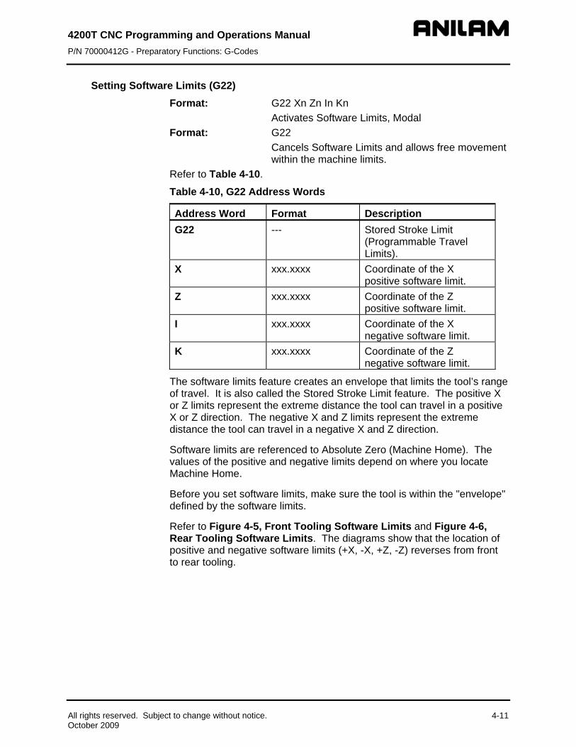
4200T CNC Programming and Operations Manual P/N 70000412G - Preparatory Functions: G-Codes
All rights reserved. Subject to change without notice. 4-11 October 2009
Setting Software Limits (G22) Format: G22 Xn Zn In Kn
Activates Software Limits, Modal Format: G22
Cancels Software Limits and allows free movement within the machine limits.
Refer to Table 4-10.
Table 4-10, G22 Address Words
Address Word Format Description G22 --- Stored Stroke Limit
(Programmable Travel Limits).
X xxx.xxxx Coordinate of the X positive software limit.
Z xxx.xxxx Coordinate of the Z positive software limit.
I xxx.xxxx Coordinate of the X negative software limit.
K xxx.xxxx Coordinate of the Z negative software limit.
The software limits feature creates an envelope that limits the tool’s range of travel. It is also called the Stored Stroke Limit feature. The positive X or Z limits represent the extreme distance the tool can travel in a positive X or Z direction. The negative X and Z limits represent the extreme distance the tool can travel in a negative X and Z direction.
Software limits are referenced to Absolute Zero (Machine Home). The values of the positive and negative limits depend on where you locate Machine Home.
Before you set software limits, make sure the tool is within the "envelope" defined by the software limits.
Refer to Figure 4-5, Front Tooling Software Limits and Figure 4-6, Rear Tooling Software Limits. The diagrams show that the location of positive and negative software limits (+X, -X, +Z, -Z) reverses from front to rear tooling.

nual unctions: G-Codes
4200T CNC Programming and Operations MaP/N 70000412G - Preparatory F
Figure 4-5, Front Tooling Software Limits
Figure 4-6, Rear Tooling Software Limits
Maximum Spindle Speed (G24) Format: G24 Sxxxx Refer to Table 4-11.
Table 4-11, G24 Address Words
Address Word Format Description G24 --- Sets the maximum
programmable spindle speed. S xxxx Maximum programmable spindle
speed, maximum four digits. G24 sets the maximum programmable spindle speed, when the CNC is in Constant Surface Speed Mode (G96). The G24 command stops the spindle from accelerating to the machine maximum spindle speed when facing to the centerline of the part. G24 is not required when using G97 (direct RPM value).
4-12 All rights reserved. Subject to change without notice. October 2009

4200T CNC Programming and Operations Manual P/N 70000412G - Preparatory Functions: G-Codes
The S-word can contain up to four digits (Sxxxx, range 0001 to 9999). Leading zeros can be omitted. Once you program a G24 command, the CNC prevents the programmed spindle speed from exceeding the entered amount (Sxxxx). The G24 command must be stated after each Gear Range statement.
Probe Move (G31) Refer to “Section 16 - Advanced Programming Features,” “Probe Move (G31).”
Thread Cutting (G33) Format: G33 Xn Zn (En or Fn) An Cn Refer to Table 4-12.
Table 4-12, G33 Address Words Address Word Description Xn X-axis end position. Zn Z-axis end position. En Threads per inch Fn Feed per revolution (pitch). An Incremental X retract distance. Cn Incremental Z retract distance.
Refer to Figure 4-7. The diagram describes the G33 Single-Pass Threading Cycle. Use G33 to program tapers and compound threading. G33 cuts to the depth to which the tool is positioned in the block preceding the G33 block. It does not contain an option for a finish pass.
X
A
CZ
tool pathpart edge
G33A
Figure 4-7, G33 Threading Cycle
NOTE: Pitch (F) = 1
Threads Per Inch (E)
All rights reserved. Subject to change without notice. 4-13 October 2009

4200T CNC Programming and Operations Manual P/N 70000412G - Preparatory Functions: G-Codes
4-14 All rights reserved. Subject to change without notice. October 2009
Refer to Table 4-13 for a sample Program Listing containing the G33 command. E or F, not both, must be programmed. At least one axis address must accompany F/E value. F (pitch) is usually used in MM programming. E (Threads per Inch) is usually used in Inch programming. All other Address Words are optional. A and C are always incremental, regardless of whether the Absolute (G90) or Incremental (G91) Mode is active.
Table 4-13, G33 Program Listing
Block Format Description N33 G33 Z-3.0 F.1 (or E10) A.2 This block will execute a
threading cycle along Z to Z-3.0, with a pitch of 0.1 and an X pullout distance of 0.2.
NOTE: All variables are sign (+/-) dependent. Moves are Outer Diameter or Inner Diameter, and move toward or away from the chuck or part centerline. The sign of the variable determines what kind of move the CNC will make. Make sure to program the appropriate sign (+/-).
Offsets (Work Coordinate System Select) (G53) Format: G53 Oxx Xn Zn The work coordinate system (absolute zero) of the CNC can be shifted to a preset dimension from machine zero using the G53 function. This function differs from G92 in that it is always in reference to machine zero, not current zero.
When programmed, G53 will automatically cancel M100 (mirror image) and G72 (scaling).
99 offsets (zero shifts) are available to the user. Offsets are stored in a table in the CNC accessed by F1 from the Tool Table Screen. This table can be updated through the program. If programmed in the part program, the values programmed will override and overwrite those in the table.
Each of the 99 offset values are designated with the letter O, followed by 1-99 (i.e., O1, O2, etc.), then the axes and their values.
The G53 block can be used in several ways as follows:
1. Use offset Number 3 from the preset table by programming G53 O3. 2. Clear any active offset by programming G53 O0. 3. Do update offset table, and do activate the shift by programming G53
On Xn Zn C. The word C tells the CNC to activate and update. 4. Do update offset table, but do not activate the shift by programming
G53 On Xn Zn.

4200T CNC Programming and Operations Manual P/N 70000412G - Preparatory Functions: G-Codes
All rights reserved. Subject to change without notice. 4-15 October 2009
Notes: 1. All of the above will clear any G92 active Tool Table.
2. Typically, the table found in the Tool Table is used (F1) to set the values and the values activated in the part program by programming G53 with O# (such as G53 O1).
3. If Table values are programmed in the part program, the values programmed will override and overwrite those in the table under F1.
4. G53 O3 is used to activate a zero point previously described in the table and is one of the most typically used.
5. G53 O0 is used to clear any offset of G53 or G92. It resets the current zero to that of machine home.
6. G53 On Xn Zn C is used as an immediate absolute zero-shift.
7. G53 On Xn Zn is used when offsets are defined at the beginning of a program. It is used strictly to set-up the offset table. No activation occurs.
8. G92 may be used in reference to (after) any G53 active, or without any G53 active (G53 O0).
9. G53 is modal, and G53 O0 (use none) is active at power-up.
10. Only axes required to be shifted need to be programmed.
11. G41/G42 should be cancelled before programming G53.
Changing Fixture Offsets in the Table To change a fixture offset to a manually entered coordinate: 1. Go to the Tool Table. 2. Press Offsets (F1). 3. Highlight Offset (row 1 to 99). 4. Press an axis key (X or Z). 5. Enter a value. Press ENTER. The CNC stores the value in the table.
Adjusting Fixture Offsets in the Table
To adjust an existing fixture offset:
1. Highlight a Fixture Offset (row 1 to 99) in the Fixture Offset Table.
2. Press the letter A key to display the message, “Enter axis and adjustment value.”
3. Type the axis to adjust (X or Z) and the amount of the adjustment. The adjustment value may be positive or negative.
4. Press ENTER to adjust the value, and display the adjusted value in the table.

4200T CNC Programming and Operations Manual P/N 70000412G - Preparatory Functions: G-Codes
4-16 All rights reserved. Subject to change without notice. October 2009
Changing Fixture Offsets Using Calibrate Keys To change offset using the calibrate keys: 1. Move the machine to the desired position. 2. Highlight the offset. 3. Press CalibX.
You will be prompted to enter a part diameter in the entry field that pops up.
4. Enter the part diameter in the entry field, and press ENTER.
5. Press CalibZ. The value will be entered to make the present location Z0.
Modal Corner Rounding/Chamfering (G59) Corner Rounding Format: G59 Rn Chamfer Format: G59 En Refer to Table 4-14.
Table 4-14, G59 Address Words
Address Word Description G59 Modal corner rounding/chamfering command. R Radius of arc used to round off each corner. E Chamfer distance used to round off each corner.
Use Modal Corner Rounding/Chamfering (G59) to round corners (blend radii) or to chamfer intersections of line-to-line, arc-to-arc and line-to-arc moves. Apply G59 to any consecutive moves for nontangent lines and arcs. You can change the blend radius or chamfer between intersections.
Use G59 on inside or outside diameter moves. The command can be used with Tool Nose Radius (TNR) Compensation. When using TNR and G59 together, make sure that the blend radius is greater than the tool radius.
The modal G59 remains in effect until canceled with a G60 code. G59 automatically initiates linear interpolation (G1).
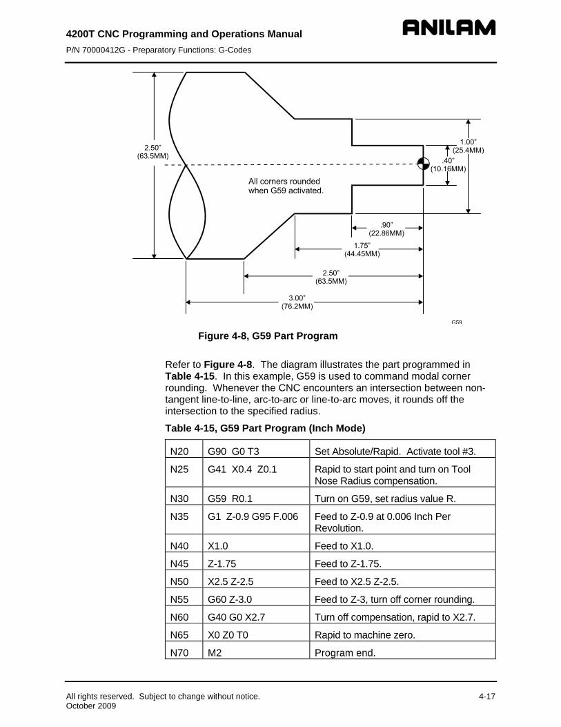
4200T CNC P/N 70000412
Programming and Operations Manual G - Preparatory Functions: G-Codes
Figure 4-8, G59 Part Program Refer to Figure 4-8. The diagram illustrates the part programmed in Table 4-15. In this example, G59 is used to command modal corner rounding. Whenever the CNC encounters an intersection between non-tangent line-to-line, arc-to-arc or line-to-arc moves, it rounds off the intersection to the specified radius.
Table 4-15, G59 Part Program (Inch Mode)
N20 G90 G0 T3 Set Absolute/Rapid. Activate tool #3.
N25 G41 X0.4 Z0.1 Rapid to start point and turn on Tool Nose Radius compensation.
N30 G59 R0.1 Turn on G59, set radius value R.
N35 G1 Z-0.9 G95 F.006 Feed to Z-0.9 at 0.006 Inch Per Revolution.
N40 X1.0 Feed to X1.0.
N45 Z-1.75 Feed to Z-1.75.
N50 X2.5 Z-2.5 Feed to X2.5 Z-2.5.
N55 G60 Z-3.0 Feed to Z-3, turn off corner rounding.
N60 G40 G0 X2.7 Turn off compensation, rapid to X2.7.
N65 X0 Z0 T0 Rapid to machine zero.
N70 M2 Program end.
All rights reserved. Subject to change without notice. 4-17 October 2009

4200T CNC Programming and Operations Manual P/N 70000412G - Preparatory Functions: G-Codes
4-18 All rights reserved. Subject to change without notice. October 2009
To change the radius between intersections, refer to the previous program. If you wanted to change the radius of the corner rounding of N45 to R0.25, you would need to insert a G59 command (G59 R0.25) between lines N40 and N45. Refer to Table 4-16.
Type the G59 command for modal corner rounding or chamfer. Include the new arc or chamfer radius. Insert the command one move before the new radius applies.
Table 4-16, G59, Changing Radius Value (Inch Mode)
N30 G59 R0.1 Turn on G59, set radius value R. N35 G1 Z-0.9 G95 F.006 Feed to Z-0.9 at 0.006 Inch Per Revolution. N40 X1.0 Feed to X1.0. N43 G59 R0.25 Round corner to radius 0.25. N45 Z-1.75 Feed to Z-1.75 (Apply Corner Rounding R.1
from N30, active G59 command.) N50 X2.5 Z-2.5 Feed to X2.5 Z-2.5 (Apply Corner Rounding
R0.25, commanded in N43).
Cancel Modal Corner Rounding (G60) Format: G60 Cancels Modal Corner Rounding/Chamfering. Next
intersection will not be rounded off/chamfered. Format: G60 Xn Zn Cancels Modal Corner Rounding/Chamfering.
Move (intersection) programmed in the same line as G60 will be rounded off/chamfered. Following intersections will not be rounded off/chamfered.
G60 cancels G59. Use the Edit Help Menus and Graphic screens to program a G60 command.
In-Position Mode (Exact Stop Check) (G61) Refer to Table 4-17.
Table 4-17, G61 and Associated G-Codes
Code Format Action G9 G9 Xx.x Zx.x Activates non-modal In-Position Mode.
Complete stop only in this block. G61 G61 Xx.x Zx.x Activates modal In-Position Mode. The
CNC stops to verify location for each targeted position. In-Position Mode remains active until changed.
G64 G64 Cancels G61 and activates the Contouring Mode.
NOTE: Rapid moves are always performed in In-Position Mode.

4200T CNC Programming and Operations Manual P/N 70000412G - Preparatory Functions: G-Codes
All rights reserved. Subject to change without notice. 4-19 October 2009
While the In-Position Mode (G61) is active, the CNC approaches target and performs an in-position check before the next move is executed. The CNC comes to a complete stop at the completion of each command. This could cause tool dwell marks to appear on the workpiece, but prevents the CNC from rounding off sharp corners.
NOTE: The In-Position and Continuous Path Tolerances are defined in the Setup Utility. The In-Position Tolerance should be closer to target than the Continuous Path Tolerance.
G61 is modal and remains in effect until canceled. Use Contouring Mode (G61) to cancel the In-Position Mode. Use G9 (Non-modal In-Position Mode) to apply the In-Position Mode to a single block.
Contouring Mode (Cutting Mode) (G64) Refer to Table 4-18.
Table 4-18, G64 and Associated G-Codes
Code Format Action G9 G9 Xx.x Zx.x Activates non-modal In-Position Mode.
Complete stop only in this block. G64 G64 Activates the Contouring Mode (also
called Continuous Path Mode). The CNC approaches target and comes within the Continuous Path Tolerance of the target position. No in-position check is made.
G61 G61 Xx.x Zx.x Cancels G64 and activates the In-Position Mode.
Format: G64
NOTE: Rapid moves always execute in In-Position Mode.
The Contouring Mode (G64), also known as Continuous Path Mode, or Cutting Mode, is active at power ON. It is used for feed moves. With the Contouring Mode activated, the CNC approaches target and comes within the Continuous Path Tolerance of the target position. No in-position check is made before the next move is executed. (During an in-position check, the CNC comes to a stop within the in-position tolerance of the target position.) This enables smooth contouring of a profile or surface.
NOTE: The machine builder defines the in-position and continuous path tolerances in the Setup Utility.
G64 is modal and remains in effect until canceled. Use Exact Stop Check (G61) to cancel the Contouring Mode. G64 initiates linear (G1) or circular interpolation (G2, G3).

4200T CNC Programming and Operations Manual P/N 70000412G - Preparatory Functions: G-Codes
4-20 All rights reserved. Subject to change without notice. October 2009
Using Macros (G65, G66, G67)
NOTE: Before using macros, you must learn how variables and parameters are used in a program or subprogram. Refer to “Section 16 - Advanced Programming Features” for an explanation of these features.
A macro is a group of instructions stored in memory and called by the main program. Macros are sophisticated, flexible subprograms which can be modal (G66) or non-modal (G65). Refer Table 4-19 for g-codes related to macro calling.
Table 4-19, Macro G-Codes
Code M/NM Format Action G65 Non-modal G65 Pn Ln
G65 Pn Executes non-modal macro (Pn), with optional repeat loop (Ln), at current location. Macro is repeated the number of times specified in command (Ln). If the L address word is omitted, the macro is executed only once. Pn = macro number (O) Ln = optional loop. Specify number of times the macro should repeat (n).
G66 Modal G66 Pn Executes macro (Pn) after each programmed move, until canceled with a G67 command. Pn = called macro
G67 Cancel G67 Cancels modal macro (G66).
Table 4-20 lists and describes the Address Words and M-codes used with macros.
Table 4-20, Macro Address Words
Address Word
Format Description
Pn Pxxxx Used in M98 command. Macro label number (O) called.
Ln Lxxxx Optional repeat command. Specify number of times macro should repeat (1 to 9999).
On N(block Number) Oxxxx
Macro label used in first line of macro for identification.
M98 M98 Pxxxx Call macro xxxx. M99 M99 End macro and return to line following
M98.

4200T CNC Programming and Operations Manual P/N 70000412G - Preparatory Functions: G-Codes
All rights reserved. Subject to change without notice. 4-21 October 2009
A subprogram consists of fixed dimensions, but a macro contains variables and parameters that can change every time the macro is used.
Macros can be stored in the same file as the main program or in a separate file. Macros stored in a separate file must be called using the File Inclusion feature.
Macros stored in the same file as the main program are defined in the same way as a subprogram (Oxxxx). Terminate the macro with M99. Enter the macro after the main program. Refer to Table 4-21. Refer to “Section 16 - Advanced Programming Features” for information on File Inclusion and passing parameters.
Table 4-21, Macro Program Listing
Program Block Description N200 M2 End main program. N210 0201 Macro number assigned. N220 [Enter macro here] Macro program. N230 N240 N250 N260 M99 End macro, return to next line of
main program. The CNC returns to the line following the Macro call (M98) Macro call in the main program.
Refer to Table 4-22. Use the M98 Macro call to call a macro from the main body of the program.
Table 4-22, Macro Call in Main Program
Program Block Description N40 N50 M98 P201 CNC executes macro O201 once, at present
location. N60 After it executes the macro (M99 encountered), the
CNC returns to the main program and performs the next programmed command.
The CNC executes the called macro (201) at Block 50 (no programmed loops). At the M99 command, the CNC returns to the next line of the main program (N60).

4200T CNC Programming and Operations Manual P/N 70000412G - Preparatory Functions: G-Codes
4-22 All rights reserved. Subject to change without notice. October 2009
Inch Mode (G70) or MM Mode (G71) Inch Mode Format: G70 MM Mode Format: G71 You can change the unit of measurement display via the Inch Mode (G70) or MM Mode (G71) commands. G70 switches the CNC to Inch Mode. Use G71 to switch to MM Mode within a program. Inch/MM Mode is usually specified at the start of a program. Refer to Table 4-23.
Table 4-23, Activating the Inch/MM Mode
Block Format Description N2 G70 G90 G0 Activates Absolute Mode and
Inch Mode. Activates Rapid Traverse.
N2 G71 G90 G0 Activates Absolute Mode and MM Mode. Activates Rapid Traverse.
All blocks following N2 will be in Inch (MM) Mode.
Absolute Mode (G90) or Incremental Mode (G91) Absolute Mode Format: G90 Incremental Mode Format: G91 In Absolute programming, all dimensions are referenced to the current Part Zero (Program Zero). In Incremental programming, all dimensions are referenced to the current tool position.
When you turn on the CNC, the Absolute or Incremental Mode specified by the machine builder is active. Absolute Mode (G90) is usually the default.
Absolute vs. Incremental Programming In Absolute Mode (G90), all dimensions are referenced to Absolute Zero. In Incremental Mode (G91), all dimensions are referenced to the current machine position. G90 and G91 are modal and remain in effect until canceled.
Refer to Figure 4-9, Absolute vs. Incremental Programming and Table 4-24, Absolute vs. Incremental Programming Examples. The table lists the Absolute and Incremental position coordinates for the diagram.

4200T CNC P/N 70000412
Programming and Operations Manual G - Preparatory Functions: G-Codes
ABSINC Figure 4-9, Absolute vs. Incremental Programming
Table 4-24, Absolute vs. Incremental Programming Examples
Absolute Incremental X Z X Z Point 1 X0 Z.1 X0 Z.1 Point 2 X0 Z0 X0 Z-.1 Point 3 X1 Z0 X1.0 Z0 Point 4 X1 Z-1 X0 Z-1 Point 5 X3 Z-1.6 X2 Z-.6 Point 6 X3 Z-2.6 X0 Z-1 Point 7 X3.8 Z-4 X.8 Z-1.4 Point 8 X4 Z-4 X.2 Z0
All rights reserved. Subject to change without notice. 4-23 October 2009

4200T CNC Programming and Operations Manual P/N 70000412G - Preparatory Functions: G-Codes
4-24 All rights reserved. Subject to change without notice. October 2009
Presetting the Axes (G92) Format: G92 Xn Zn X is the distance in X from the tool tip to Part Zero (usually a diameter value). Z is the distance in Z from the tool tip to Part Zero. These distances are measured with the tool sitting at Machine Home.
Refer to Table 4-25. The Absolute Zero Preset (G92) code resets axes to X0, Z0 or to any other pre-determined position. On a G92 command, the CNC resets the absolute position displays for X and Z. This adjusts the axes’ displays to the actual position of the tool to be used.
Table 4-25, Absolute Zero Preset (G92) Listing
Program Example Description G92 X0 Z0 Sets the current tool position as Part Zero. The axes’
position displays change to read X0 and Z0. G92 X2 Z4 Sets Part Zero 2 inches in X and 4 inches in Z from the
tool tip. The axes’ position displays read X2 and Z4. NOTE: Make sure the tool is resting at Machine Home.
Part Zero (Program Zero) is usually the front face, centerline of a part. All programmed moves are referenced from Part Zero. When it is used to set Part Zero (X0, Z0), the G92 command tells the control the distance from Part Zero to the tip of the tool. You have to measure this distance, referenced to Machine Home, in X and Z prior to programming G92. The measured distances become part of the G92 command.
Before you complete the measurements, place the tool at Machine Home to ensure that the tool is in the appropriate spot. If you do not position the tool properly, the measurements will be incorrect.
NOTE: There are three ways to establish Part Zero on a workpiece for a particular tool: Tool Length Offsets (T-codes), work coordinate offsets (G53), or Absolute Zero Presets (G92). T-codes are the best way to set Part Zero. Refer to “Section 9 - Tool Page and Tool Management” for information on how to set Part Zero with Tool Length Offsets.
Refer to Table 4-26. The example program moves the tool to Machine Home and changes the current tool position (Machine Home) to X4.0000 and Z6.0000.
Table 4-26, G92, Presetting Axes' Position Display
N01 O2001 *SAMPLE-G92 Program # and name. N02 G28 XZ Homes X and Z-axes. N03 G92 X4 Z6 Sets current position to X4, Z6.
NOTE: Anilam recommends that you do not use G92 to set Part Zero. If the machine loses power, this reference point will be lost.

4200T CNC Programming and Operations Manual P/N 70000412G - Preparatory Functions: G-Codes
All rights reserved. Subject to change without notice. 4-25 October 2009
Cutting Feedrates in Feed per Minute (G94) G94: (FPM) Inch or MM per minute feedrate
programming. Refer to Table 4-27. Feedrates programmed in Feed Per Minute (FPM) (G94) are either in Inch (G70) or MM (G71) Mode. In FPM Mode, the moves are made at a specified rate per minute. The G-code is followed by an F-code that designates the corresponding feed rate.
Table 4-27, FPM (G94) Inch and MM Formats
Mode Format Feedrate Inch Mode (G70) G94 F1 1.0 Inch/Min. Millimeter (G71) G94 F1 1.0 MM/Min.
When programming lathes and turning centers, feedrates are usually programmed in Inch Per Revolution (G95).
NOTE: In all modes of operation, if the spindle is OFF, G94 must be active to move the axes with any one of the following modals: G1, G2, G3, G5.
NOTE: If jogging or using the Handwheel, G94 and G95 are ignored and the Manual Panel settings defined by the builder are used.
Cutting Feedrates in Feed Per Revolution (G95) Format: G95 (FPR) Inch or MM per revolution feedrate
programming. Refer to Table 4-28. Feedrate Per Revolution (FPR) (G95) is the default feedrate most commonly used in lathes and turning centers. In FPR Mode, moves are programmed in reference to the distance moved per revolution of the spindle. In order to use Feed Per Revolution, a spindle encoder (with a Zero Marker (Index Pulse)) must be installed on the machine.
Table 4-28, Inch and MM Feedrates
Mode Format Feedrate Inch Mode (G70) F 0.008 0.008 In./Rev. Millimeter (G71) F 0.20 0.20 MM/Rev.
Maximum Feed Values The maximum available feedrate (for G94 and G95) is set by the machine builder and cannot be exceeded.

4200T CNC Programming and Operations Manual P/N 70000412G - Preparatory Functions: G-Codes
4-26 All rights reserved. Subject to change without notice. October 2009
Setting Spindle Speed to Constant Surface Speed (G96)
CAUTION: Program a G24 Sxxxx (Maximum Spindle RPM) prior to G96. This prevents the RPM of the spindle from reaching maximum speed when a move to the centerline (X0) is programmed.
CAUTION: Do not use CSS when threading. This operation requires the threading tool to be able to retrace its motion over and over again, at changing diameters, with each pass.
NOTE: The capability to use this feature is determined by the builder. Format: G96 Sxxxx
Constant Surface Spindle Speed (CSS) Most turning operations are performed in CSS. In the Constant Surface Speed (CSS) Mode (G96), the CNC adjusts the spindle RPM to maintain a constant surface speed. The S Word specifies the surface feet per minute (or, in meters per minute if in metric mode) at which the spindle rotates. To find the actual RPM, use the following formula: RPM = 3.8 X (Surface feet per minute divided by the diameter) Spindle speed is inversely proportional to the distance from the part centerline. If the calculated RPM exceeds the machine’s maximum RPM, the CNC generates an error message.
Setting Spindle Speed to Constant Revolutions Per Minute Speed (G97) Format: G97 Sxxxxx Revolutions Per Minute (RPM)
In Revolutions per Minute (RPM) Mode (G97), the CNC rotates the spindle at a constant rate. The S-Word provides the rate. If the entered RPM exceeds the machine’s maximum RPM for the active gear range, the CNC generates an error message.
Threading passes and center cutting operations (tapping, drilling and reaming) must be performed in RPM Mode. Most other turning operations are performed in Constant Surface Speed (G96) Mode.
When the program is run and the CNC encounters the G97 command, it activates the Revolutions per Minute Mode. The CNC will remain in RPM Mode until the command is changed or canceled.

4200T CNC Programming and Operations Manual P/N 70000412G - Canned Cycles
All rights reserved. Subject to change without notice. 5-1 October 2009
Section 5 - Canned Cycles
Programming a Z-Axis Turning/Boring Cycle with a Defined Profile (G73) Format G73 Wn An Rn Sn Cn Bn Pn In Jn Kn
Refer to Table 5-1. The table lists the Address Words that define the G73 (longitudinal) and G74 (radial) area clearance cycles.
Table 5-1, G73 and G74 Address Words
Address Word Description W Input Subprogram Number. Subprogram number in
which the part profile is programmed. Store in the same file as the main program or use shape created in the shape editor. Required.
A Depth per Pass. Depth of material removed per rough pass (per side). Required.
R X Finish Stock. Amount of material left in X after roughing cycle is finished. Removed during finish pass. Optional.
S Z Finish Stock. Amount of material left in Z after roughing cycle is finished. Removed during finish pass. Optional.
C Finish pass indicator. 0 (no finish pass) or 1 (a finish contour pass will be completed after the roughing cycle). Required.
B OD=1, ID=0: 1 (completes passes along the Z-axis, away from the centerline) or 0 (completes passes along the Z-axis, toward the centerline). Required.
P Undercut. Use value of 1 if undercuts are present in the profile to be rough/finish cut. Leave the parameter unassigned if no undercuts are present. Optional.
I X In Feed. Plunge Feedrate. (G94=Z In Feed) Optional.
J Rough feed. Feedrate for the roughing cycle. Optional.
K Finish feed. Feedrate for the finish cycle. Optional.
Refer to Figure 5-1, G73 Turning/Boring with Defined Profiles. G73 rough machines a workpiece into a given profile, along the Z-axis (longitudinal). The profile shape is defined by a subprogram. The subprogram number is called in the cycle using the parameter W.

4200T CNC Programming and Operations Manual P/N 70000412G - Canned Cycles
The subprogram profile is programmed after the end of the main program and uses the letter O. The profile program can contain lines, arcs and angles. You can use the shape editor. An optional finish pass removes the finish stock amount defined by parameters R (X) and S (Z).
NOTE: The X ending point of the shape should be the largest diameter point for OD and smallest diameter point for ID on the shape.
A different feedrate can be programmed for rough (J) and finish (K) passes. Parameter B determines whether the roughing cycle is an outer diameter profile (B = 1) or an inner diameter profile (B = 0). The finish pass is taken directly along the part profile.
Figure 5-1, G73 Turning/Boring with Defined Profiles
Refer to Figure 5-2. The diagram shows the part programmed in Table 5-2, G73 Part Program. The program demonstrates how to use G73 to perform a longitudinal Area Clearance (turning/boring) cycle.
Figure 5-2, G73 Part Program
5-2 All rights reserved. Subject to change without notice. October 2009

4200T CNC Programming and Operations Manual P/N 70000412G - Canned Cycles
All rights reserved. Subject to change without notice. 5-3 October 2009
Table 5-2, G73 Part Program
Program Block Description N1 G70 G90 G0 X0 Z0 T0 Sets Inch/MM Mode and
Absolute Mode. Places machine at X0,Z0 with no tool offsets active.
N2 X3.7 (93.9) Z0 T1 Activates T1, rapids to X start position (.2” standoff).
N3 G1 X-.03 (-1) G95 F.008 (0.2)
Faces to X-0.03" (X-1mm) past centerline at 0.008" (.2mm) per revolution.
N4 G0 X3.7 (93.9) Z.1 (2.0) Rapids to start position of Area Clearance Cycle.
N5 G73 W9 A.2 (5) R.02 (.5) S.005 (.1) C1 B1 J.02 (.5) K.01 (.25)
Sets parameters for G73 and activates cycle.
N6 T0 X0 Z0 Cancels T1 offsets, rapids to home position.
N7 M2 Ends Program, returns to block N1.
N8 Blank for easy distinction between Main and Sub-programs.
The following subprogram describes the part profile called into the main program above. The CNC calculates actual moves based on the profile described in the subroutine. N10 O9 (Subprogram) Establishes name of
Subprogram (O9). N11 G0 X1 (X25.4) Z.1 (2) Rapids to start point of profile. N12 Z-1 (-25.4) Feeds to Z-1" (Z-25.4mm). N13 X2 (50.8) Z-1.5 (-38.1) Feeds up angle to X2 Z-1.5
(X50.8 Z-38.1). N14 Z-2.25 (-57.15) Feeds to start of radius. N15 G3 X3.5 (88.9) Z-3 (-76.2) R.75 (19.05)
Feeds around radius CCW.
N16 G1 X3.7 (93.9) Feeds away from part diameter to clear the part.
N17 M99 Ends Subprogram.
NOTE: All variables are sign (+/-) dependent. Moves can be defined as Outer Diameter/Inner Diameter, and toward or away from the chuck or part centerline. The positive/negative direction (sign of the variable) determines what kind of move is made by the CNC. Ensure that the appropriate sign (+/-) is programmed.

4200T CNC Programming and Operations Manual P/N 70000412G - Canned Cycles
Programming an X-Axis Facing/Boring Cycle with Defined Profile (G74) Format G74 Wn An Rn Sn Cn Bn Pn In Jn Kn
Refer to Table 5-1, G73 and G74 Address Words. The table lists the Address Words that define the G73 (longitudinal) and G74 (radial) Area Clearance Cycles.
Refer to Figure 5-3. The G74 Area Clearance cycle rough machines a workpiece into a given profile, along the X-axis (radial). The tool must be positioned properly before the cycle is executed.
Figure 5-3, G74 Facing/Boring Cycle with Defined Profile
The profile shape is defined by a subprogram. The subprogram profile is programmed after the end of the main program and uses the letter O. The profile program contains lines, arcs and angles. Use the shape editor. An optional finish pass removes the finish stock amount given by parameter R (X) or S (Z).
A different feedrate can be programmed for rough (J) and finish (K) passes. The B address word determines whether the roughing cycle passes are toward (B = 1) or away from (B = 0) the part centerline. The finish pass is taken directly along the part profile.
5-4 All rights reserved. Subject to change without notice. October 2009

4200T CNC Programming and Operations Manual P/N 70000412G - Canned Cycles
0.2" R. 2 places(5.08 MM)
0.60 Dia.(82.55MM)
0.70"(17.78MM)
0.10" X 45 deg. CHAMFER(2.54MM)
0.40"(10.16MM)
0.05" X 45 deg.CHAMFER(1.27MM)
3.25" Dia.(82.55MM)
74-2 Figure 5-4, G74 Part Program
Refer to Figure 5-4. The diagram shows the part programmed in Table 5-3. The program demonstrates how to use G74 to perform a radial Area Clearance (facing/boring) cycle.
Table 5-3, G74 Part Program
Part Program Description N1 G70 (G71) G90 G0 X0 Z0 T0
Sets Inch/MM and Absolute Modes. Sends tool to Machine Home (X0,Z0) and cancels tool offsets.
N2 X3.45 (87.63) Z0 T1
Activates T1, rapids to start position of Area Clearance Cycle.
N3 G74 W8 A.05 (1.28) R.02 (.508) S.005 (0.127) C1 B1 J.02 (0.508) K.01 (0.254)
Sets parameters for G74 and activates cycle.
N4 G0 X0 Z0 T0
Cancels T1 offsets, rapids to Machine Home.
N5 M2
Ends Program, returns to block N1.
N6
Blank for easy distinction between Main and Subprograms.
All rights reserved. Subject to change without notice. 5-5 October 2009

4200T CNC Programming and Operations Manual P/N 70000412G - Canned Cycles
5-6 All rights reserved. Subject to change without notice. October 2009
The following subprogram describes the part profile called into the main program above. The CNC calculates actual moves based on the profile described in the subroutine. N7 O8 (Subprogram) Establishes name of Subprogram
(O8). N8 G0 X3.45 (87.63) Z-0.45 (-11.43)
Rapids to start point of profile.
N9 G1 X3.25 (82.55) Feeds to X position. N10 X3.15 (80.01) Z-0.4 (-10.16)
Feeds down chamfer to X2 Z-1.5 (X80.01 Z-11.43).
N11 X1.2 (30.48) Faces down to start of radius. N12 G2 X.8 (20.32) Z-0.2 (-5.08) R.2 (5.08)
Feeds around radius CW.
N13 G1 Z-0.1 (-2.54) Feeds to start of 2nd chamfer Z-0.1" (Z-2.54).
N14 X0.6 (15.24) Z0 Feeds down chamfer. N15 M99 Ends Subprogram.
NOTE: All variables are sign (+/-) dependent. Moves can be defined as Outer Diameter/Inner Diameter, and toward or away from the chuck or part centerline. The positive/negative direction (sign of the variable) determines what kind of move is made by the CNC. Make sure to program the appropriate sign (+/-).

4200T CNC Programming and Operations Manual P/N 70000412G - Canned Cycles
All rights reserved. Subject to change without notice. 5-7 October 2009
Programming a Z-Axis Rough Turning or Boring Cycle (G76)
Use the Z-Axis Rough Turning Cycle (G76) to clear stock along the Z-axis (outer diameter, O.D.) or to bore a hole (inner diameter, I.D.). Refer to Table 5-4 for a list and description of the Address Words associated with G76. Compensation, including Tool Nose Radius Compensation, is not available when G76 is active.
Boring Format G76 Zn Xn Cn An Bn Z-Axis Rough Turning Format G76 Zn Xn Cn An Bn Dn En
G76 can be used for I.D. or O.D cuts. If B is negative, the CNC performs an inner dimension cut (boring). If B is positive, the CNC performs an outer dimension cut (rough turning cycle).
Table 5-4, G76 Address Words
Address Word Description Z Incremental Z distance from start to finish (length).
Required. X Incremental X distance from start to end diameter
(excludes B). Required. C Maximum incremental depth per cut. Required. A Incremental Z distance from start to final pull-out.
Optional. B Incremental X standoff distance from the diameter.
Default: 0.1"/2mm for O.D and -0.1"/-2mm for I.D. If no value provided, the CNC assumes the default. Optional.
D Incremental Z distance from start to final pull-in. Optional.
E Rear angle of tool in reference to X+ direction. Must be a negative value. Optional.

4200T CNC Programming and Operations Manual P/N 70000412G - Canned Cycles
G81 Address Words Refer to Figure 5-5. The G76 turning cycle removes stock material along the Z-axis, from the outer diameter of the work. The tool must be positioned appropriately before the canned cycle begins. B determines the standoff position in X from which the tool advances to the start of the turning cycle.
C
B
X
A
Z
D
E
G76-1
Figure 5-5, G76 Z-Axis Roughing Cycle The CNC calculates the depth of each pass and the number of passes necessary to reach finish depth (X). The actual depth per pass will not exceed the programmed maximum depth (C). The CNC advances the tool along at the calculated depth per pass, and at the desired profile (angular or rectangular). The rear angle of the cutting tool (E) cannot exceed the slope of the finished cut (X divided by D).
Once the cycle is completed, the CNC returns to the G76 starting coordinates. If you want a finish pass, you must program it separately.
5-8 All rights reserved. Subject to change without notice. October 2009

4200T CNC Programming and Operations Manual P/N 70000412G - Canned Cycles
Programming an X-Axis Radial (Facing) Roughing Cycle (G77) Format: G77 Xn Zn Cn An Bn Dn En Refer to Table 5-5 for a list and description of the Address Words used to define G77.
Table 5-5, G77 Address Words
Address Word Description X Incremental X distance from start to finish (length).
Required. Z Incremental Z distance from start to end diameter
(excludes B). Required. C Maximum incremental depth per cut. Required. A Incremental X distance from start to final pullout.
Optional. B Incremental Z standoff distance from face.
Default: O.D. 0.1” or 2MM. Optional. D Incremental X distance from start to final pull-in.
Optional. E Incremental rear angle of tool, referenced to the
positive Z direction (Z-axis to trailing edge of tool). Must be a positive value. Optional.
Refer to Figure 5-6. The G77 radial facing cycle removes stock material along the X-axis. The tool must be positioned appropriately before the canned cycle begins.
Figure 5-6, G77 Radial Roughing/Boring Cycle
All rights reserved. Subject to change without notice. 5-9 October 2009

4200T CNC Programming and Operations Manual P/N 70000412G - Canned Cycles
G77 can be used for I.D. or O.D cuts. B determines the standoff position in Z, from which the tool advances to the start of the facing cycle. The CNC calculates the depth of each pass and the number of passes necessary to reach finish depth (Z). The actual depth per pass will not exceed the programmed maximum depth (C). The CNC advances the tool along at the calculated depth per pass, and the desired profile (angular or rectangular). The rear angle of the cutting tool (E) cannot exceed the slope of the finished cut. No compensation can be performed during the G77 canned cycle (including Tool Nose Radius Compensation). Once the cycle is completed, the CNC returns to the starting coordinates. If a finish pass is desired, it must be programmed separately.
Refer to Figure 5-7. The diagram shows how G77 can alternately be used for inner (boring) and outer (roughing) diameter cutting.
Figure 5-7, G77 Roughing and Boring Cycles
NOTE: All variables are sign (+/-) dependent. Moves can be defined as Outer Diameter/Inner Diameter, and toward or away from the chuck or part centerline. The positive/negative direction (sign of the variable) determines what kind of move is made by the CNC. Make sure that the appropriate sign (+/-) is programmed.
5-10 All rights reserved. Subject to change without notice. October 2009

4200T CNC Programming and Operations Manual P/N 70000412G - Canned Cycles
Programming a Pecking Cycle (G78) Format G78 Zn Rn Fn In Pn Refer to Table 5-6 for a list and description of the Address Words used to define a Pecking Cycle (G78).
Table 5-6, G78 Address Words
Address Word Description Z Absolute hole depth in Z. Optional. R Distance from starting position to surface to be
drilled, in Z. (Default: .10”/2MM). Optional. F Feedrate. Optional. I Maximum Peck distance. Required. P Retract distance from surface of work to end position
in Z. Point to which tool retracts after hole depth is reached. Optional.
Refer to Figure 5-8 for a description of the peck drilling cycle (G78). G78 is used for drilling holes along the Z-axis. No motion occurs along the X-axis.
RZ
G78
Figure 5-8, G78 Pecking Cycle
Before running the cycle, you must position the tool at the start position. The CNC feeds from the Z start position (R) to the specified hole depth (Z), at a given feedrate (F). The number of pecks and depth per peck depend on the hole depth (Z) and number of pecks necessary to complete the cycle. After the peck drilling cycle is complete, the CNC rapids to the return height (P), before proceeding to the next program block.
NOTE: Drilling cycles G78 (Peck Drilling) and G79 (Chip Break Drilling) require the Z start (R) to be 0.10"/2MM from the surface to be drilled. The Z return (P) is optional. If P is not given, the CNC returns to the Z start position at the end of the cycle.
All rights reserved. Subject to change without notice. 5-11 October 2009

4200T CNC Programming and Operations Manual P/N 70000412G - Canned Cycles
Programming a Chip Break Cycle (G79) Format G79 Zn Rn Fn In Jn Kn Wn Un Pn
Refer to Table 5-7 for a list and description of the Address Words used to define a Chip Break Cycle (G79).
Table 5-7, G79 Address Words
Address Word Description Z Absolute hole depth in Z. Required. R Starting position of cycle in Z. Required. F Feedrate. Optional. I Z depth of first peck (positive dimension). Required. J Amount to subtract from subsequent pecks (I-J)
(positive dimension). Required. K Minimum peck distance (positive dimension).
Required. W Chip break increment (positive dimension). Optional.U Incremental depth between full retracts (positive
dimension). Optional. P Point to which tool retracts after hole depth is
reached. Optional.
I
RZ
K G79
Figure 5-9, G79 Chip Break Cycle
Refer to Figure 5-9. G79 is the chip-break peck-drilling cycle, generally used for peck drilling medium to deep holes. G79 allows you to tailor Address Words to the material and tool types used in deep hole drilling.
During the chip break cycle, the CNC feeds from the starting position to the first peck depth. Before commencing the next peck, the CNC rapid retracts the tool by the chip break increment (W). Then, the tool advances to the next calculated peck depth (I minus J). This procedure continues until the tool reaches retract depth (U), or until final hole depth is reached. At the end of the cycle, the CNC advances to the next programming block.
5-12 All rights reserved. Subject to change without notice. October 2009

4200T CNC Programming and Operations Manual P/N 70000412G - Canned Cycles
The peck distance will never be more than I or less than K.
To prevent binding of the chips, tool, and workpiece in deep-hole drilling, as the depth increases, the peck distance (J) decreases. The retract depth (U) variable allows the programmer to fully retract the tool from the hole, at specified incremental depths.
Programming a Longitudinal Grooving Cycle (G81) Format G81 Zn Xn Wn Bn Dn
Refer to Table 5-8 for a list and description of the Address Words used to define a Longitudinal Grooving Cycle (G81).
Table 5-8, G81 Address Words
Address Word Description Z Total incremental Z dimension of groove (length).
Required. X Incremental X distance (depth) from start radius to
end radius (excludes B). Required. W Tool width. Required. B Incremental X standoff distance from diameter (0.1
in/2mm outer diameter; -0.1in/2mm inner diameter). Optional.
D Dwell time at bottom of groove, in seconds. Optional.
Refer to Figure 5-10. G81 creates a groove along the longitudinal (Z) axis. Use a groove-cutting tool for this cycle. The cycle has built-in compensation for tool width. Position the tool appropriately (with the tool width taken into consideration) before the canned cycle begins.
W
B
X
Z
X0, Z0
Figure 5-10, G81 Address Words
Use G81 for inner diameter or outer diameter cuts. B determines the standoff position in X, from which the tool advances to the start of the grooving cycle.
All rights reserved. Subject to change without notice. 5-13 October 2009

4200T CNC Programming and Operations Manual P/N 70000412G - Canned Cycles
After the tool reaches total depth (X), it remains at the bottom of the groove until the dwell time (D, optional) elapses. The CNC calculates the number and width of passes from the total length (Z) required and the tool width (W). After the cycle terminates, the CNC returns to the starting coordinates of the canned cycle.
NOTE: All variables are sign (+/-) dependent. Moves can be defined as Outer Diameter/Inner Diameter, and toward or away from the chuck or part centerline. The positive/negative direction (sign of the variable) determines what kind of move is made by the CNC. Make sure to program the appropriate sign (+/-).
Refer to Figure 5-11. The diagram shows the part programmed in Table 5-9, G81 Programming Example. Metric equivalents are given in parentheses.
G81-2
Tool Width 0.125"(3.175MM)
Tool PositionX1.2, Z-0.725
0.6"(15.24MM)
0.875"22.23MM
1.0"25.4MM
0.75"(19.05MM)
X0, Z0
Figure 5-11, G79 Chip Break Cycle
5-14 All rights reserved. Subject to change without notice. October 2009

4200T CNC Programming and Operations Manual P/N 70000412G - Canned Cycles
All rights reserved. Subject to change without notice. 5-15 October 2009
Table 5-9, G81 Programming Example
Program Block Description N1 O7 *GROOVY Establishes program name and
number. N2 G90 G70 G0 T0 X0 Z0 M5 Sets Absolute/Inch/Rapid Modes.
Cancels tool offsets and positions tool at X0, Z0.
N3 T1 *.125 (3.175) WIDE GROOVE INSERT
Activates tool length offsets for Tool 1. Contains a comment regarding tool width.
N4 X1.2 (30.48) Z-.725 (-18.415) M3 S980
Positions axes, turns on spindle and sets spindle speed to 980.
N5 G95 F.0012 (.03) Sets feedrate. N6 G81 Z-.75 (-19.05) X-.0625 (-1.588) W.125 (3.175) B.1(2)
Defines and activates G81 canned cycle.
N7 G0 T0 X0 Z0 M5 Cancels tool offset, positions axes at Machine Home and turns off the spindle.
N8 M2 End of program. Return to N1.
Programming a Radial Grooving Cycle (G82) Format G82 Zn Xn Wn Bn Dn
Refer to Table 5-10 for a list and description of the Address Words used to define a Radial Grooving Cycle (G82).
Table 5-10, G82 Address Words
Address Word Description X Incremental X distance (length) from start radius to
end radius (excludes B). Required. Z Total incremental Z dimension of groove (depth).
Required. W Tool width. Required. B Incremental X standoff distance from diameter (0.1
in/2mm outer diameter; -0.1in/2mm inner diameter). Optional.
D Dwell time at bottom of groove, in seconds. Optional.
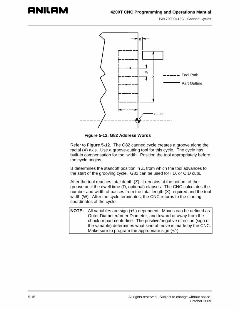
4200T CNC Programming and Operations Manual P/N 70000412G - Canned Cycles
W
B
Z
X
X0, Z0
Part Outline
Tool Path
Figure 5-12, G82 Address Words
Refer to Figure 5-12. The G82 canned cycle creates a groove along the radial (X) axis. Use a groove-cutting tool for this cycle. The cycle has built-in compensation for tool width. Position the tool appropriately before the cycle begins.
B determines the standoff position in Z, from which the tool advances to the start of the grooving cycle. G82 can be used for I.D. or O.D cuts.
After the tool reaches total depth (Z), it remains at the bottom of the groove until the dwell time (D, optional) elapses. The CNC calculates the number and width of passes from the total length (X) required and the tool width (W). After the cycle terminates, the CNC returns to the starting coordinates of the cycle.
NOTE: All variables are sign (+/-) dependent. Moves can be defined as Outer Diameter/Inner Diameter, and toward or away from the chuck or part centerline. The positive/negative direction (sign of the variable) determines what kind of move is made by the CNC. Make sure to program the appropriate sign (+/-).
5-16 All rights reserved. Subject to change without notice. October 2009
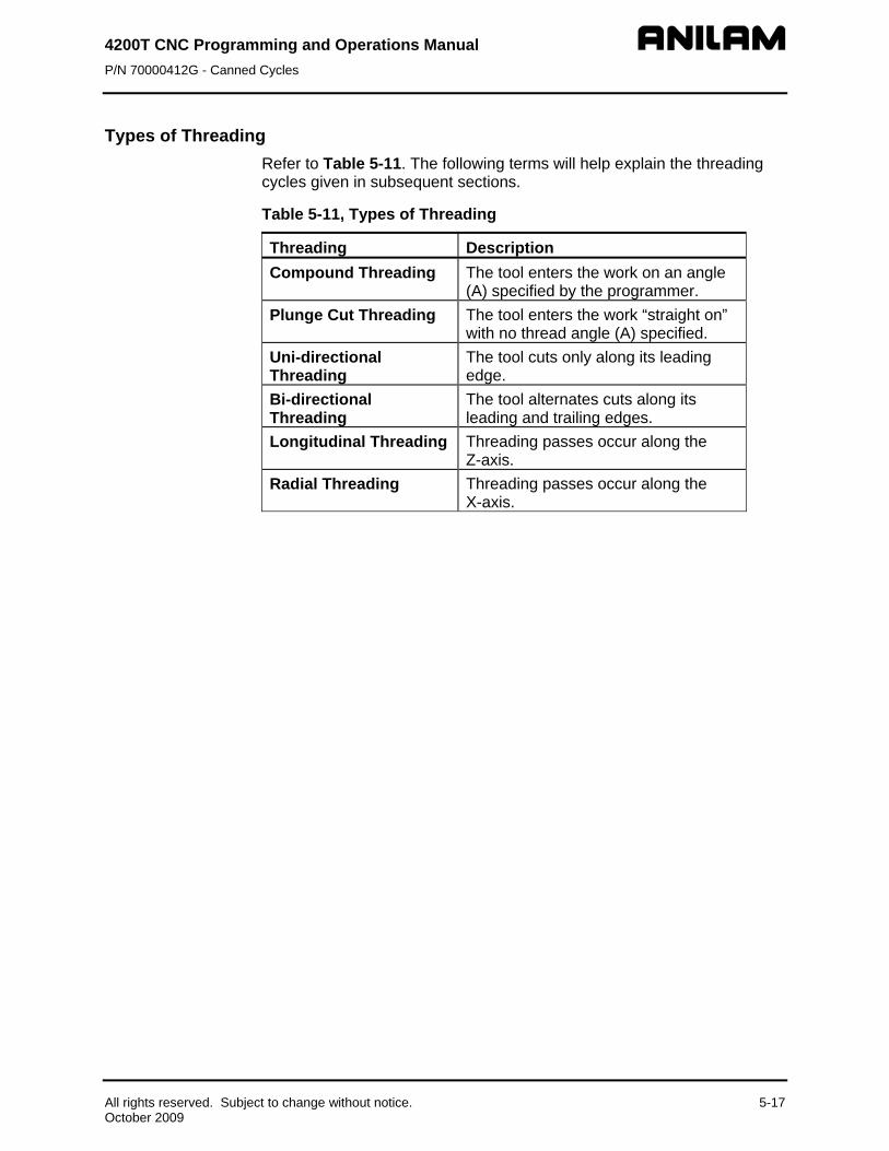
4200T CNC Programming and Operations Manual P/N 70000412G - Canned Cycles
All rights reserved. Subject to change without notice. 5-17 October 2009
Types of Threading Refer to Table 5-11. The following terms will help explain the threading cycles given in subsequent sections.
Table 5-11, Types of Threading
Threading Description Compound Threading The tool enters the work on an angle
(A) specified by the programmer. Plunge Cut Threading The tool enters the work “straight on”
with no thread angle (A) specified. Uni-directional Threading
The tool cuts only along its leading edge.
Bi-directional Threading
The tool alternates cuts along its leading and trailing edges.
Longitudinal Threading Threading passes occur along the Z-axis.
Radial Threading Threading passes occur along the X-axis.

4200T CNC Programming and Operations Manual P/N 70000412G - Canned Cycles
5-18 All rights reserved. Subject to change without notice. October 2009
Cutting Longitudinal Threads with Canned Cycles (G83, Uni-directional) Format G83 En Zn Cn Dn An Sn Rn Xn Vn Bn Wn
Refer to Table 5-12 for a list and description of the Address Words used to define a Uni-directional Longitudinal Threading Cycle (G83).
Table 5-12, G83 Address Words Address Word Description E Threads per inch. Used in Inch programming. F Pitch (single pass threading) or amount of travel in
Z per revolution (multi-pass threading). Used in MM programming. NOTE: Use E or F, but not both.
Z Incremental distance in the Z-axis from Tool start position to finish point (length of threading pass).
C Incremental depth of the first cut (depth of cut per side for first pass). Does not include B parameter.
D Incremental depth of the thread (depth of thread per side). Does not include B parameter. Default: Pitch x 0.6134 (60 degree thread).
A Thread angle, 60 degrees for standard threads. Default: 0 degrees for a straight plunge thread.
S Number of passes at final depth. Default: 1.
R Incremental Z-axis pullout distance. Creates a 2-axis pullout move. Default: 0 causes the tool to pullout at 90 degrees to the threading pass.
X Distance moved in the X-axis during a threading pass. Default: 0 straight thread.
V Angle of tapered thread. Default: 0 NOTE: When programming a tapered thread, use X or V parameter, but not both.
B Distance in the X-axis from the tool tip to the work diameter per side. Default: Inch = 0.1. Outside diameter default: Inch = -0.1. Inside diameter default: MM = 2. Outside diameter default: MM = -2 Inside diameter. Tool must be positioned the standoff distance away from the diameter in the block prior to the threading canned cycle.
W Used to program the number of starts in a multiple start thread. Default: 1 (single start thread).

4200T CNC Programming and Operations Manual P/N 70000412G - Canned Cycles
Refer to Figure 5-13. The figure describes the motion of the CNC during a G83 canned cycle. The G83 canned cycle creates a longitudinal thread along the Z-axis, utilizing multiple-pass threading. G83 supports an X-axis taper distance or angle.
R
V
A
BC
G83
tool pathpart edge
Z
D
X
Figure 5-13, G83 Uni-direction Compound or Plunge Thread Cutting
NOTE: All variables are sign (+/-) dependent. Moves can be defined as Outer Diameter/Inner Diameter, and toward or away from the chuck or part centerline. The positive/negative direction (sign of the variable) determines what kind of move is made by the CNC. Make sure to program the appropriate sign (+/-).
All rights reserved. Subject to change without notice. 5-19 October 2009

4200T CNC Programming and Operations Manual P/N 70000412G - Canned Cycles
5-20 All rights reserved. Subject to change without notice. October 2009
Cutting Longitudinal Threads with Canned Cycles (G84, Bi-directional) Format G84 En (Fn) Zn Cn Dn An Sn Rn Bn Wn Refer to Table 5-13 for a list and description of the Address Words used to define a Bi-directional Longitudinal Threading Cycle (G84).
Table 5-13, G84 Address Words
Address Word Description E Threads per inch. Used in Inch programming. F Pitch (single pass threading) or amount of travel in Z
per revolution (multi-pass threading). Used in MM programming. NOTE: Use E or F, but not both.
Z Incremental distance in the Z-axis from Tool start position to finish point (length of threading pass).
C Incremental depth of the first cut (depth of cut per side for first pass). (Does not include B parameter).
D Incremental depth of the thread (depth of thread per side). (Does not include B parameter.) Default: Pitch x 0.6134 (60 degree thread).
A Thread angle, 60 degrees for standard threads. Default: 0 degrees for a straight plunge thread.
S Number of passes at final depth. Default: 1.
R Incremental Z-axis pullout distance. Creates a 2-axis pullout move. Default: 0 causes the tool to pullout at 90 degrees to the threading pass.
B Distance in the X-axis from the tool tip to the work diameter per side. Default: Inch = 0.1 Outside Diameter Default: Inch = -0.1 Inside Diameter. Default: MM = 2 Outside Diameter Default: MM = -2 Inside Diameter Tool must be positioned the standoff distance away from the diameter in the block prior to the threading canned cycle.
W Used only in multiple pass threading, the number of staggered starts used to reach depth. Default: 1. NOTE: Specifying the number of starts changes the way the CNC interprets all other threading variables.

4200T CNC Programming and Operations Manual P/N 70000412G - Canned Cycles
Refer to Figure 5-14. The figure describes the motion of the CNC during a G84 canned cycle. The G84 canned cycle creates a longitudinal thread along the Z-axis, utilizing multiple-pass threading. G84 does not support an X-axis taper distance or angle, but allows bi-directional threading.
CB
R
A
G84
D
Z
tool pathpart edge
Figure 5-14, G84 Bi-directional Compound Threading
NOTE: All variables are sign (+/-) dependent. Moves can be defined as Outer Diameter/Inner Diameter, and toward or away from the chuck or part centerline. The positive/negative direction (sign of the variable) determines what kind of move is made by the CNC. Make sure to program the appropriate sign (+/-).
All rights reserved. Subject to change without notice. 5-21 October 2009

4200T CNC Programming and Operations Manual P/N 70000412G - Canned Cycles
G84 Programming Example
Figure 5-15, G84 Programming Example
Refer to Figure 5-15 for a diagram of the part programmed in Table 5-14. The Listing provides a sample Program Listing for a G84 threading canned cycle. Metric equivalents are provided in parentheses following the inch measurements.
Table 5-14, G84 Program Listing
Program Block CNC Response G0 X0.7 (17) Z0.2 (5.08) T3 Positions tool to starting point,
activates Tool #3 offsets. N27 G84 E13 (F2) Z-1.2625 (32.068) C-.015 (-0.4)
Completes programmed threading pass. Threading Cycle E (F)= Threads Per Inch or pitch/mm (metric) Z = Incremental Thread Length C = 1st pass depth of cut
N28 X0 Z0 T0 Cancels offsets, rapids home.
5-22 All rights reserved. Subject to change without notice. October 2009

4200T CNC Programming and Operations Manual P/N 70000412G - Canned Cycles
All rights reserved. Subject to change without notice. 5-23 October 2009
Cutting Radial Threads with Canned Cycles (G85, Uni-directional) Format: G85 En (Fn) Xn Cn Dn An Sn Rn Zn Vn (Bn) Wn Refer to Table 5-15 for a listing and description of Address Words associated with the G85 comman7d.
Table 5-15, G85 Address Words
Address Word Description E Threads per inch. Used in Inch programming. F Pitch (single pass threading) or amount of travel in
X per revolution (multi-pass threading). Used in MM programming. NOTE: Use E or F, but not both.
X Incremental distance in the X-axis from Tool start position to finish point (length of threading pass).
C Incremental depth of the first cut (depth of cut for first pass). (Does not include B parameter.)
D Incremental depth of the thread (depth of thread). (Does not include B parameter) Default: Pitch x 0.6134 (60 degree thread).
A Thread angle, usually 60 degrees. Default: 0 degrees for a straight plunge thread.
S Number of passes at final depth. Default: 1. R Incremental X-axis pullout distance. Creates a 2-
axis pullout move. Default: 0, causes the tool to pullout at 90 degrees to the threading pass.
Z Distance moved in the Z-axis during a threading pass. Default: 0 straight thread.
V Angle of tapered thread. Default: 0. NOTE: When programming a tapered thread use Z or V parameters, but not both.
B Distance in the Z-axis from the tool tip to the work face. Default: Inch = 0.1 Default: MM = 2. (Tool must be positioned the Standoff distance away from the face in the block prior to the threading canned cycle.)
W Used to program the number of starts in a multiple start thread. Default: 1 (single start thread).
Refer to Figure 5-16, G85 Canned Cycle. The figure describes the motion of the CNC during a G85, multiple-pass threading cycle. During a G85 cycle, a plunge or compound thread is cut along the X-axis (part face). The programmer must position the tool before running the cycle. After the cycle is executed, the tool returns to the starting coordinates for the cycle.

4200T CNC Programming and Operations Manual P/N 70000412G - Canned Cycles
R
A
CB
V
G85
Z
D
X
tool pathpart edge
Figure 5-16, G85 Canned Cycle
NOTE: All variables are sign (+/-) dependent. Moves can be defined as Outer Diameter/Inner Diameter, and toward or away from the chuck or part centerline. The positive/negative direction (sign of the variable) determines what kind of move is made by the CNC. Make sure to program the appropriate sign (+/-).
5-24 All rights reserved. Subject to change without notice. October 2009

4200T CNC Programming and Operations Manual P/N 70000412G - Canned Cycles
G85 Radial (Face) Plunge Thread Example
X0, Z0
1.40"(35.56MM)
4.00"(101.6MM)
G85-B
SCROLL THDPITCH = 0.125" (3MM)
.20"(5.08MM)
Figure 5-17, Radial (Face) Threading Example
Refer to Figure 5-17. The figure shows a part diagram for a G85 cycle. Refer to Table 5-16 for the Program Listing. Metric equivalents are provided in parentheses.
Table 5-16, G85 Program Listing
Program Block Description N26 G0 X4.4 (111.76) Z0.1 (2) T5 Position Tool to Start Point. N27 G85 E.125 (F3) X-1.5 (-37.64) C-.025 (-.635) R-.1 (-3)
G85 Threading Cycle E = Pitch F = Lead (MM) X = Incremental Thread Length C = 1st pass depth of cut R = Incremental pull-out distance
N28 X0 Z0 T0 Cancel Offsets, Rapids Home.
All rights reserved. Subject to change without notice. 5-25 October 2009

4200T CNC Programming and Operations Manual P/N 70000412G - Canned Cycles
5-26 All rights reserved. Subject to change without notice. October 2009
Cutting Radial Threads with Canned Cycles (G86, Bi-directional) Format G86 En (Fn) Xn Cn Dn An Sn Rn Bn Wn Refer to Table 5-17 for a listing and description of the Address Words associated with the G86 canned cycle.
Table 5-17, G86 Address Words
Address Word Description E Threads per inch. Used in Inch
programming. F Pitch (single pass threading) or amount of
travel in X per revolution (multi-pass threading). Used in MM programming. NOTE: Use E or F, but not both.
X Incremental distance in the X-axis from tool start position to finish point (length of threading pass).
C Incremental depth of the first cut (depth of cut for first pass). (Does not include B parameter).
D Incremental depth of the thread (depth of thread). (Does not include B parameter) Default: Pitch x 0.6134 (60 degree thread).
A Thread angle, 60 degrees for standard threads. Default: 0 degrees for a straight plunge thread.
S Number of passes at final depth. Default: 1.
R Incremental X-axis pullout distance. Creates a 2-axis pullout move. Default: 0 causes the tool to pullout at 90 degrees to the threading pass.
B Distance in the Z-axis from the tool tip to the work face. Default: Inch = 0.1 Default: MM = 2 Tool must be positioned the Standoff distance away from the face in the block prior to the threading canned cycle.
W Used only in multiple pass threading, the number of staggered starts used to reach depth. Default: 1. NOTE: Specifying number of starts changes the way the CNC interprets

4200T CNC Programming and Operations Manual P/N 70000412G - Canned Cycles
Refer to Figure 5-18. The diagram describes the motion of the CNC during the G86, multiple-pass thread cutting. In Radial Bi-directional threading (G86), passes are performed along the X-axis (face). G86 is designed for compound threading. The operator must position the tool before running the G86 canned cycle. After the cycle is executed, the tool returns to the starting coordinates for the canned cycle.
R
A
CB
D
X
tool pathpart edge
G86 Figure 5-18, G86 Canned Cycle
NOTE: All variables are sign (+/-) dependent. Moves can be defined as Outer Diameter/Inner Diameter, and toward or away from the chuck or part centerline. The positive/negative direction (sign of the variable) determines what kind of move is made by the CNC. Make sure to program the appropriate sign (+/-).
All rights reserved. Subject to change without notice. 5-27 October 2009

4200T CNC Programming and Operations Manual P/N 70000412G - Canned Cycles
5-28 All rights reserved. Subject to change without notice. October 2009
Tapping a Hole with a Canned Cycle (G87)
NOTE: The machine must support spindle M-codes (spindle forward, spindle reverse and spindle off) in order to use this cycle.
Format G87 Zn Rn Fn Pn Dn Refer to Table 5-18 for a listing and description of the Address Words associated with the G87 canned cycle.
Table 5-18, G87 Address Words
Address Word Description Z Absolute hole depth R Initial Z start point (CNC rapids to R) F Threads per Inch (TPI) in Inch mode, or
Lead (Distance between threads) in MM mode. P Alternate Z return point after hole depth (CNC feeds
to P, if specified after completing the cycle). If no P value is given, the CNC returns to the starting point (R) at the conclusion of the cycle.
D Dwell time. A dwell time value in seconds can be entered. You may require this feature because of the time required to stop and reverse the spindle. If “D” is set, the control will dwell at the start and bottom of the hole.

4200T CNC Programming and Operations Manual P/N 70000412G - Canned Cycles
Refer to Figure 5-19. The diagram describes the Address Words used to define a G87 Tapping Cycle. G87 is used for tapping holes. The CNC feeds from the retract plane to the depth of the hole in Z. The spindle stops and reverses motion, and retracts the tool from the hole. The CNC returns the tool to the starting position (R, or to alternate finish position, P) reversing spindle motion before advancing to the next program block.
RZG87
Figure 5-19, G87 Tapping Cycle
NOTE: Not all machines contain the spindle encoder necessary for Inch Per Revolution (G95) programming.
All variables are sign (+/-) dependent. Moves can be defined as Outer Diameter/Inner Diameter, and toward or away from the chuck or part centerline. The positive/negative direction (sign of the variable) determines what kind of move is made by the CNC. Make sure to program the appropriate sign (+/-).
All rights reserved. Subject to change without notice. 5-29 October 2009

4200T CNC Programming and Operations Manual P/N 70000412G - Canned Cycles
5-30 All rights reserved. Subject to change without notice. October 2009
Programming a Boring Cycle (G88) Format G88 Zn Xn Cn An Bn Refer to Table 5-19 for a listing and description of the Address Words associated with the G88 canned cycle.
Table 5-19, G88 Address Words
Address Word Description Z Incremental Z distance from start to finish (length).
Required. X Incremental X distance from start to end diameter
(excludes B). Required. C Maximum incremental depth per cut. Required. A Incremental Z distance from start to final pull-out.
Optional. B Incremental X standoff distance from the diameter.
Default: 0.1inch/2mm for O.D. and -0.1inch/-2mm for I.D. If no value provided, the CNC assumes the default. Optional.

4200T CNC Programming and Operations Manual P/N 70000412G - Canned Cycles
Refer to Figure 5-20. The G88 boring cycle removes stock material along the Z-axis, from the inner diameter of the work. The tool must be positioned appropriately before the canned cycle begins. Perform boring cycles only on a workpiece that has been pre-drilled. B determines the standoff position in X, from which the tool advances to the start of the boring cycle.
B
CZ
X
G76-3 Figure 5-20, G88 Boring Cycle
The CNC calculates the depth of each pass and the number of passes necessary to reach finish depth (Z). The actual depth per pass will not exceed the programmed maximum depth (C). The CNC advances the tool along at the calculated depth per pass.
Once the cycle is completed, the CNC returns to the starting coordinates for the canned cycle. If a finish pass is desired, it must be programmed separately.
All rights reserved. Subject to change without notice. 5-31 October 2009

4200T CNC Programming and Operations Manual P/N 70000412G - Canned Cycles
5-32 All rights reserved. Subject to change without notice. October 2009
Lathe Tool Probe Cycles (Option) This document describes operation and an overview of the lathe tool probe canned cycles available on the 4200T CNC product. Probing is an option on the 4200T CNC. The cycles provided perform the most common tool probing functions. Custom cycles to perform specific functions can be written using the G31 primitive and parametric programming. Refer to “Section 16, Probe Move (G31)” for more details. If Probing has been added post-sale, besides Setup Utility changes, there may be Integral Programmable Intelligence (IPI) program modifications required.
The lathe tool probe cycles are only supported on machines with homing with a permanent X and Z machine position. The method described assumes the use of negative tool-length offsets. In this method, the Tool-Length Offset (TLO) for each tool represents the distance from the tool tip at machine home to the centerline of the spindle in X and to a fixed known point in Z such as the spindle nose or chuck face. This method requires the use of a Z work coordinate offset.
Tool probing does not allow scaling to be active. If scaling is on before calling the canned cycle, it will be deactivated when the cycle is complete.
IMPORTANT: Check with machine builder for operation of probing hardware.
Probes in lathes typically have an arm. If the arm is automatic, an M-code is commonly used to move the arm down and another M-code is used to move the arm up. The machine builder or probe installer will provide these details.
Before using your tool probe and tool probe cycles, you must setup the probe following the probe manufacturer’s specifications.
This section covers the following topics:
Tool Probe G-code Cycle Designations
Macro Variable and System Variable Settings
Detailed description of all tool probe cycles
The lathe tool probe will update the tool registers only. If you are going to use the tool being measured after the probing cycle, you must recall that tool for the new offsets to be active.
For probing system parameter setup information, refer to 4200T CNC Setup Utility Manual, P/N 70000414, and “Macro Variable and System Variable Settings.”

4200T CNC Programming and Operations Manual P/N 70000412G - Canned Cycles
All rights reserved. Subject to change without notice. 5-33 October 2009
Tool Probe G-code Cycle Designations Before running any of these probing cycles you must go into Probing Setup and set the probing setup parameters.
G150 Tool Probe Calibration Cycle This is used to set the X and Z datum for diameter, length, and establish the center of the probe stylus.
NOTE: Calibration must be done at least once before using the tool probe. Once the probe has been calibrated, calibration does not need to be done unless the probe is moved or the Z offset reference surface is changed.
G151 Tool Preset Cycle Preset the tool length (Z) and diameter (X) in the tool table. The probe must be calibrated before you run this cycle.
G154 Tool Wear/Breakage Cycle Checks the tool and gives an alarm if not within tolerance. If the tool wear is greater than allowed tolerance, then the tool must be changed. If less than the allowed tolerance, the cycle updates the wear register(s).
G146 Protected Probe Positioning Cycle This is used to position the tool around the probe during a program for automated tool preset (G151) and wear adjustment (G154). The tool arm must be in the proper position before trying to use any of these cycles.
Macro Variable and System Variable Settings Before you set the parameters for the tool probe you must:
Know the size of the calibration standard.
Ensure when entering the values in the parameters that you are in the same units (inch/metric) as when you are running the tool preset canned cycle. Set the units in the Setup Utility to the units in which you are going to run the cycles. When changing from inch to mm or from mm to inch. First change on the Setup Options screen, then go back to Setup Options, Operator Setup and Control Software, change Default units (#2) to inch or mm as required.

4200T CNC Programming and Operations Manual P/N 70000412G - Canned Cycles
5-34 All rights reserved. Subject to change without notice. October 2009
To set the Probe Parameters:
• On the Software Options menu, select Software Utility.
• On the Setup Options menu, select Builder Setup.
• On the Builder Setup menu, select Probing.
• On the Probing Setup menu, set the following options:
1. Set Inspection probe type, this should be set to Corded, Cordless, or Cordless SG for a lathe type probe.
2. Do not set Inspection probe stylus diameter – Not used.
3. Do not set Inspection probe standard diameter – Not used.
NOTE: The parameter labels starting with “Inspection” do not relate to these cycles and are only present for future use.
4. Set Tool probe stylus width, the lathe probe width. This needs to be an exact value and is used by the cycle to calibrate the probe stylus. It is also used to position the tool properly. The probe stylus should be a perfectly square rectangle. [For example, set to 0.5906 inch (15 mm).]
5. Set Positioning FeedRate while probing, the feedrate the control will use while positioning the probe around the part. This is the feed-rate used to position the tool around the probe. This should be the fastest feed-rate to save time but not so fast as to jeopardize the safety of the probe. [For example, set to 70 in/min (1778 mm/min).]
6. Set First pick feedrate, the feedrate the control will use while making its initial touch finding the surface it is measuring. [For example, set to 20 in/min (508 mm/min).]
7. Set Second pick feedrate, the feedrate the control will use after making its initial touch finding the surface it is measuring. This is the feed-rate used for the final probe pick. This should be relatively slow. [For example, set to 1 in/min (25.4 mm/min).]
8. Set Retract amount after first touch, the amount the tool retracts from the probe stylus after the first pick. [For example, set to 0.0200” (0.5080 mm).]
9. Set Invert probe logic to No for standard Normally Open (N.O.) probe interface and to Yes for a Normally Closed (N.C.) probe interface. This parameter should not to be changed except by a qualified probe installer or the OEM.
All defaults, i.e. G90/91, G95/94, etc., must be reset by the programmer or operator after running a probing canned cycle because they can and will be changed by the canned cycle. Tools must be reactivated after a probing cycle is run to insure the new offset has taken effect.

4200T CNC Programming and Operations Manual P/N 70000412G - Canned Cycles
Probe Orientation Probe orientation is the position the tool is placed. G146 may be used to position the tool. If orientation 2 is to be used, the tool would be placed at the back right corner of the stylus at the appropriate distance from X and Z. This is parameter (D) when required in a cycle.
See Figure 5-21 for the tool orientations to the probe stylus.
ORIENTATION
62
7
1
5
48
3
Figure 5-21, Probe Orientations
The orientation parameter (D) must be entered in cycles requiring this parameter. The most commonly used orientations are:
D2 For the rear tool post turning tools
D3 For the front tool post turning tools
Lathe Tool Probe G-code Cycle Designations The following summarizes the cycles available:
G150 Tool Probe Calibration Cycle The Tool probe must be calibrated before presetting a tool offset. To calibrate the tool probe you must have a calibration standard in the tool turret or holder that can touch the probe stylus on at least two adjacent sides. Once mounted in the tool turret, the calibration standard must have an offset activated to a known fixed point on the lathe relative to machine home. This is usually the chuck face and the center of spindle rotation to the edge of the calibration standard that will contact the probe stylus. Before calling the G150 calibration cycle, you must have that tool offset active. Next, bring the probe arm down and jog the calibration standard to within 0.2”/5mm of the probe stylus into one of the orientations listed above, preferably this should be orientation 2 or 3 so that the G150 cycle can touch two adjacent sides of the probe stylus to calculate and store the calibration data. Example: G150 D2. The cycle will only touch two sides and then will calculate the other two sides of the stylus based on the width of the stylus entered probe setup utility or in the “S” parameter. Once the cycle has calibrated the probe stylus, it will store the data that represents the distance from the fixed point on the machine, (the chuck face and spindle center line), to each side of the probe stylus. Once that data is stored, it will then be used to calculate the tool offset when using the G151 and G154 cycles.
All rights reserved. Subject to change without notice. 5-35 October 2009

4200T CNC Programming and Operations Manual P/N 70000412G - Canned Cycles
5-36 All rights reserved. Subject to change without notice. October 2009
G151 Tool Preset Cycle
Bring the probe arm down and jog the tool into the orientation position. The tool that is being set must be active before calling this cycle. Execute the G151 cycle with at least the “D” parameter set to the tool orientation to the probe. Example: G151 D 2. This will load the X and/or Z offset into the tool table, which is the distance from machine home to the spindle center-line in X and the chuck face (or where ever you had chosen as a reference point when calibrating the tool) in Z. After setting all the tools, the operator MUST put in a G53 offset, which is the positive distance from the chuck face in the Z-axis only, to the front face of the part. This can be done by placing the part in the chuck and calling any tool, then manually jogging the tool to the face of the part. Then write the number in the “Program” section Z register and entering that number into the Z offset register of the work coordinate you wish to use.
CAUTION: This work coordinate MUST be active at all times when machining or the Z zero position will be the face of the chuck instead of the part face causing a crash. When a new part is being setup and machined and the tools are remaining the same, the operator only needs to adjust the Z-axis work coordinate for all the tools to be properly set. It is not necessary to re-set all the tool offsets. If the tool offset needs to be somewhere other then the edge of the part that is touching the probe stylus, you will need to enter an amount into the “C” parameter to add a shift moving the offset over to another place on the tool such as the center of a threading tool.
G154 Tool Wear/Breakage Cycle Bring the probe arm down and jog or use the G146 protected probe positioning cycle to move the tool into the orientation position. The tool that is being set must be active before calling this cycle. Execute the G154 cycle with at least the “D” to set the tool orientation to the probe and one or both “I” or “K” parameters. Example: G154 D 2 I .001 K .002 where “I” and “K” are the maximum amounts that the X and Z offsets can be off before generating an error. This will check to make sure the amount of wear for X and/or Z is not over the specified amount and update the wear registers if the “U” parameter is set to “1”. If the tool offset is somewhere other then the edge of the part that is touching the probe stylus, you will need to enter the same amount into the “C” parameter as was used when doing the initial tool set using the G151 Tool Preset Cycle. The tool must be positioned in relation to the probe stylus using the G146 protected probe move cycle prior to calling this cycle.
G146 Protected Probe Positioning Cycle This is intended to be used to position the tool around the probe during a program for automated tool wear adjustment (G154). The tool arm must be in the proper position before trying to use any of these cycles. The machine builder or probe installer will be able to tell you the codes associated to bringing the probe arm up or down if automatic.

4200T CNC Programming and Operations Manual P/N 70000412G - Canned Cycles
All rights reserved. Subject to change without notice. 5-37 October 2009
Description of Tool Probe Cycles This section contains detailed descriptions of the tool probe cycles: • Establishing a Position on the Machine • Tool Probe Calibration Cycle (G150) • Tool Preset (G151) • Tool Wear/Breakage Cycle (G154) • Protected Probe Positioning Cycle (G146)
Establishing a Position on the Machine
X will normally be set to the center of the spindle.
1. Turn a part in the machine and measure the diameter and set the tool-length offset (TLO) for X in the normal way using the offset of any active tool.
2. Use the same tool for the Z-axis and G150 (Tool Probe Calibration Cycle).
This must be completed before G150 is run. A nominal position must first be set before using these cycles. This can be done the same way as setting a TLO; but in this case, it is put G53 Offset Table. The face of chuck or any convenient position along the Z-axis can be selected. The position should be a repeatable position. This position is also set in G53 Offset Table. When this is done, activate the G53 offset. You are now ready to set the TLO's. Note after G151 Tool preset as been run for all tools, it will be necessary to adjust Z G53 offset to the front of part or to wherever Z zero is required to be set.

4200T CNC Programming and Operations Manual P/N 70000412G - Canned Cycles
5-38 All rights reserved. Subject to change without notice. October 2009
Tool Probe Calibration Cycle (G150) Format: G150 An Bn Sn Dn
This cycle is used to calibrate the probe. This is used to set the X and Z datums establishing the center of the probe stylus and the effective probe stylus size for setting tool diameter registers. Refer to Table 5-20.
Table 5-20, G150 Address Word
Address Word
Description
A If n=1, calibrates all four sides of the stylus. When n=0, calibrates two sides. [Default: 1] (Optional)
B Distance away from the probe stylus. [Default: 0.2” (5.08mm)] [Range: 0.01” (0.254 mm) – 1.0” (25.4 mm] (Optional)
S Stylus width and length, if set in the Setup Utility the value is passed from there. (Optional)
D Tool orientation to the probe stylus. See Figure 5-21, Probe Orientations. (Required) [Range: 1 to 8]
To calibrate the tool probe: 1. Manually jog the tool to less then 0.2” (5.08 mm) of the stylus. This
the start position to calibrate the tool.
2. From the manual mode, type G150 D(n), and press the START button. Where D is the tool orientation to the probe stylus.

4200T CNC Programming and Operations Manual P/N 70000412G - Canned Cycles
All rights reserved. Subject to change without notice. 5-39 October 2009
Tool Preset (G151) Format: G151 Bn Cn Sn Dn
This tool preset (G151) can be run from within a program or from the manual mode. Refer to Table 5-21.
Table 5-21, G151 Address Words
Address Word
Description
B (Distance away) The distance away from the probe stylus. [Default: 0.2” (5.08 mm)] [Range: 0.01"/0.254mm to 1.0"/25.4mm] (Optional)
C (Shift Amount) Offset value where the center of the tool is required to be zero. (Optional)
S (Stylus Size) The stylus width and length, if set the Setup Utility the value is passed from there. (Optional)
D Tool orientation to the probe stylus. See Figure 5-21, Probe Orientations. (Required) [Range: 1 to 8]
Jog machine to within 0.2” (5.08 mm) of stylus X and Z and on the tool page place the highlight on the tool to be calculated. Enter the program into the control and run in Auto.
To enter value into the offset tool page:
1. The Tool# that is active will automatically have its TLO updated.

4200T CNC Programming and Operations Manual P/N 70000412G - Canned Cycles
5-40 All rights reserved. Subject to change without notice. October 2009
Tool Wear/Breakage Cycle (G154) Format: G154 Bn Cn Sn Dn In Kn Un
Refer to Table 5-22.
Table5-22, G154 Address Word
Address Word
Description
B (Distance away) The distance away from the probe stylus. [Default: 0.2” (5.08 mm)] [Range: 0.01"/0.254mm to 1.0"/25.4mm] (Optional)
C (Shift Amount) Offset value where the center of the tool is required to be zero. (Optional)
S (Stylus Size) The stylus width and length, if set the Setup Utility the value is passed from there. (Optional)
D Tool orientation to the probe stylus. See Figure 5-21, Probe Orientations. (Required) [Range: 1 to 8]
I (Maximum Xwear Adjustment) Maximum X-axis wear allowed. If less than I maximum value, the system will adjust the wear offset in the tool page. If the X-axis wear is over the I maximum value, the control will alarm when the maximum limit set in I or K has been exceeded. If undefined, will not adjust X wear table. (Required – One or both I and/or K)
K (Maximum Zwear Adjustment) Maximum Z-axis wear allowed. If less than K maximum value, the system will adjust the wear offset in the tool page. If the X-axis wear is over the K maximum value, the control will alarm when the maximum limit set in I or K has been exceeded. If undefined, will not adjust Z wear table. (Required – One or both I and/or K)
U (1=Update, 0=No) If set to "1", it will update the wear registers and the control will alarm when the maximum limit set in I or K has been exceeded. If this is undefined or set to 0, the G154 cycle will not update the wear registers each time it checks a tool. (Optional)
To check the tool length and/or tool diameter for wear or breakage: Jog to position as for G151. If C is used in the original setting, it should be entered at this time.

4200T CNC Programming and Operations Manual P/N 70000412G - Canned Cycles
All rights reserved. Subject to change without notice. 5-41 October 2009
It is possible to use G146 to position the probe before using the G154 cycle.
Protected Probe Positioning Cycle (G146) Format: G146 Xn Zn Fn
When an X and Z move is programmed using the G146 (Protected Probe Positioning Cycle), the control will stop and alarm if the probe stylus is triggered before reaching the target set in the X and Z parameters.
Before setting this parameter, the probe should be calibrated. Jog each tool to within 0.2” (5.08mm) of the stylus and enter the numbers into the X and Z parameters.
G146 can be used to position tools close to the probe before using G154 (Tool Wear/Breakage Cycle0. The probe must be in position before the G146 cycle is run.
The G146 Protected Probe Positioning Cycle can be run from within a program or manual mode. Refer to Table 5-23.
Table 5-23, G146 Address Words
Address Word
Description
X X position from the original position set
Z Z position from the original position set
F Feedrate at which to travel to this position.
(Optional)
To use the Protected Probe Positioning Cycle: 1. Type G146 Xn Zn Fn. If this is run from inside a program, this line
needs to be repeated for every move you wish to make.
2. Execute that line in Manual or Auto by pressing START.


4200T CNC Programming and Operations Manual P/N 70000412G - Program Editor
All rights reserved. Subject to change without notice. 6-1 October 2009
Section 6 - Program Editor
Activating the Program Editor Program blocks are written with the Program Editor. Activate the Program Editor to put the CNC in Edit Mode. You must create program files before you can write or edit programs. Refer to “Section 10 - Program Management” for instructions on how to create new programs. You can activate the Program Editor from the Program Directory or the Manual screen.
When the Program Editor activates from the Program Directory, the highlighted program opens for editing.
When the Program Editor is activated from the Manual screen, the selected program opens for editing. All programming procedures written in this section take place in Edit Mode.
Activating the Edit Mode from the Manual Screen
To activate the Edit screen from the Manual screen:
1. Select the appropriate program and press Edit (F3). The Edit screen activates and Ins (F3) highlights.
Activating the Edit Mode from the Program Directory
To activate the Edit screen from the Program Directory:
1. Highlight a program in the Program Directory. 2. Press Edit (F8). The Edit screen activates and Ins (F3) highlights.
Activating the Edit Mode from Draw Graphics
To activate the Edit screen from Draw Graphics, press Edit (F2). The Edit screen activates and Ins (F3) highlights. See Figure 6-1, Edit Screen.
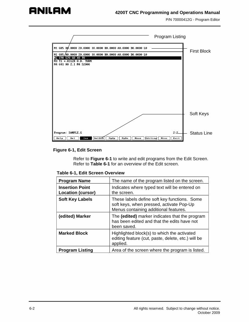
4200T CNC Programming and Operations Manual P/N 70000412G - Program Editor
First Block
Program Listing
6-2 All rights reserved. Subject to change without notice. October 2009
Status Line
SoftkeysS s oft Key
Figure 6-1, Edit Screen
Refer to Figure 6-1 to write and edit programs from the Edit Screen. Refer to Table 6-1 for an overview of the Edit screen.
Table 6-1, Edit Screen Overview
Program Name The name of the program listed on the screen. Insertion Point Location (cursor)
Indicates where typed text will be entered on the screen.
Soft Key Labels These labels define soft key functions. Some soft keys, when pressed, activate Pop-Up Menus containing additional features.
(edited) Marker The (edited) marker indicates that the program has been edited and that the edits have not been saved.
Marked Block Highlighted block(s) to which the activated editing feature (cut, paste, delete, etc.) will be applied.
Program Listing Area of the screen where the program is listed.

4200T CNC Programming and Operations Manual P/N 70000412G - Program Editor
All rights reserved. Subject to change without notice. 6-3 October 2009
Edit Soft Keys Refer to Table 6-2 for a list of the soft keys in the edit mode.
Table 6-2, Edit Soft Keys
Soft Key Label No. Function Help F1 Activates Edit Help Menu. Del F2 Deletes the single character located at the
insertion point. Ins F3 Sets the CNC to the Insert Mode. Typed
characters will be inserted at the insertion point, without overwriting the existing text.
DelBlk F4 Deletes a single block, located at the insertion point.
PgUp F5 Returns the display to the previous page of the Program Listing.
PgDn F6 Advances the display to the next page of the Program Listing.
Move F7 Activates the Move Pop-Up Menu. The Move Pop-Up Menu contains features which enable you to go to the beginning or end of a line or program. It also contains word and line search features.
Editing F8 Activates the Editing Pop-Up Menu. The Editing Pop-Up Menu contains features which enable you to perform editing functions within a single program or between two programs. This includes: inserting, undeleting blocks, and canceling unsaved edits to a block. It also includes cutting and pasting blocks within a program or writing and reading blocks between programs.
Misc F9 Activates the Misc Pop-Up Menu. The Misc Pop-Up Menu contains features that allow you to record and recall recorded keystrokes, repeat programming commands, print the Program Listing, and display or edit another program.
Exit F10 Exits the editor.

4200T CNC Programming and Operations Manual P/N 70000412G - Program Editor
6-4 All rights reserved. Subject to change without notice. October 2009
Editing Shift Soft Keys The Edit screen contains ten soft keys when it activates. Four additional soft keys activate when you press SHIFT. Refer to Table 6-3 for a list of shift soft keys in the edit mode. To activate any SHIFT soft key: 1. In Edit Mode, press SHIFT and then press the appropriate soft key (F4,
F7, F8, or F10).
Table 6-3, Edit Shift Soft Keys
Soft Key Label No. Function UnDelBlk SHIFT + F4 Restores up to 128 deleted blocks, beginning
with the last one deleted. FinNext SHIFT + F7 Advances to the next occurrence of the text
specified in the Find Word feature. Find Word is located in the MOVE Pop-Up Menu.
ChaNext SHIFT + F8 Advances to the next occurrence of the text specified in the Change Word feature and changes the text to the replacement text specified in Change Word. Change Word is located in the MOVE Pop-Up Menu.
Quit SHIFT + F10 Exits the editor without saving edits made to the Program Listing.
Deleting a Character To delete a character: 1. In Edit Mode, use the ARROWS to place the insertion point on the
character being deleted. 2. Press Del (F2). The character is deleted.
Inserting Text to Overwrite Previous Text To insert text into a program while overwriting previously entered text: 1. In Edit Mode, press Ins (F3) to switch it OFF. Ins (F3) is no longer
highlighted.
2. Place the insertion point where the text is to be inserted. Enter the new text. The CNC replaces previously typed text with the new text.
Inserting Text without Overwriting Previous Text Use Ins (F3) to activate Insert Mode. In Insert Mode, the CNC inserts typed text at the insertion point, without overwriting previously entered text: 1. In Edit Mode, press Ins (F3), unless it is already highlighted. 2. Place the insertion point where the text is to be inserted. Type the
new text. The new text is placed at the insertion point. Previously typed text is advanced forward as new text is typed.

4200T CNC Programming and Operations Manual P/N 70000412G - Program Editor
All rights reserved. Subject to change without notice. 6-5 October 2009
Deleting a Program Block There are two ways to delete program blocks from a Program Listing:
Press DelBlk (F4) to delete one block at a time. Use the BLOCK Operations Delete feature to delete several blocks at
a time.
To delete a program block using DelBlk (F4):
1. In Edit Mode, use the ARROW keys to place the insertion point on the program block being deleted.
2. Press DelBlk (F4). The CNC deletes the block. Delete program blocks by first marking the block and then using the BLOCK Operations Delete feature. To mark the program block and delete it: 1. In Edit Mode, first mark the program blocks to be deleted. Press
Editing (F8). The soft key highlights and the EDITING Pop-up Menu activates listing Mark Block as one of the options.
2. Highlight Mark Block, and press ENTER. 3. Use the ARROW keys to scroll to the desired blocks to be marked.
Press ENTER. The blocks are now marked. 4. Press Editing (F8). The soft key highlights and the EDITING Pop-Up
Menu again activates. 5. Use the ARROW keys to highlight BLOCK Operations. Press ENTER.
The BLOCK operation Pop-Up Menu activates.
6. Use the ARROW keys to highlight Delete. Press ENTER. The CNC deletes the marked blocks.
NOTE: To unmark blocks that are marked (without doing any block operation), go to Edit, then Mark Block, and press ENTER.
Page Up/Down through the Program Listing With long programs, it is convenient to move the Program Listing display up and down a whole page at a time. To page up or page down the Listing: 1. In Edit Mode, press PgUp (F5) to advance forward or PgDn (F6) to go
back in the program. The CNC advances or goes back a page at a time.
4200T CNC Programming and Operations Manual P/N 70000412G - Program Editor
6-6 All rights reserved. Subject to change without notice. October 2009
Going to a Line of the Program Listing The Go to Line feature enables you to go to any line in the Program Listing. Go to Line operates independently of block numbering. Blocks can be numbered sequentially by any increment (1, 5, 10...). Go to Line counts the lines of the program in increments of 1 (1 [starting block], 2, 3...). When this feature activates, the CNC goes to the line number you have specified, regardless of how the blocks are numbered.
Block # Line # N10 Line 1 N20 Line 2 N30 Line 3
1. In Edit Mode, press Move (F7). The soft key highlights and the MOVE Pop-Up Menu activates.
2. Highlight Go to Line.
3. The following message is displayed, ”Go to line:“ Type the appropriate line number, and press ENTER. The CNC places the insertion point at that line number.
Advancing to the Beginning or End of a Block To advance to the beginning or end of a program block: 1. In Edit Mode and with the insertion point on any block of the program,
press Move (F7). The soft key highlights and the MOVE Pop-Up Menu activates.
2. Highlight End of Line, and press ENTER. The insertion point advances to the end of the block.
– or – Highlight Start of line, and press ENTER. The insertion point returns to the beginning of the block.
Advancing to the First or Last Block of a Program To advance to the first or last block of a program: 1. In Edit Mode, press Move (F7). The soft key highlights and the
MOVE Pop-Up Menu activates. 2. Highlight End of program, and press ENTER. The insertion point
advances to the last block of the program. – or –
Highlight Start of program, and press ENTER. The insertion point returns to the first block of the program.

4200T CNC Programming and Operations Manual P/N 70000412G - Program Editor
All rights reserved. Subject to change without notice. 6-7 October 2009
Searching the Program Listing for Selected Text Use the Find Word and Find Next features to search blocks for selected text. Enter the text to be found. The CNC searches out the first (Find Word) and subsequent occurrences (Find Next) in the Program Listing. To find all occurrences of text in a program: 1. In Edit Mode, place the insertion point at the beginning of the
program. (Find Word and Find Next only search forward in the program.)
2. Press Move (F7). The soft key highlights and the Move Pop-Up Menu activates.
3. Highlight Find Word, and press ENTER. 4. The following message is displayed, “Enter Word to Find:” Type the
text to be found, and press ENTER. The insertion point advances to the first occurrence of the text in the program.
5. To advance to the next occurrence of the text, press Move (F7). The soft key highlights and the Move Pop-Up Menu activates.
6. Highlight Find Next, and press ENTER. The CNC advances to the next occurrence of the text in the program.
7. Use this method to search for all occurrences of the text in the Program Listing.
NOTE: You can also activate Find Next from the SHIFT soft key menu. To activate Find Next from the SHIFT soft key menu:
1. In Edit Mode, press SHIFT. This activates the SHIFT soft key menu.
2. Press FinNext (F7). This soft key performs the same function as Find Next, located in the MOVE Pop-Up Menu. Each time you press the soft key, the CNC advances to the next occurrence of the text specified in Find Word.
Inserting a Blank Line in the Program Listing You can insert a line at the insertion point. All subsequent lines will be moved down one line in the program. To insert a blank line: 1. In Edit Mode and with the insertion point where the blank line is to
appear, press Editing (F8). The soft key highlights and the EDITING Pop-Up Menu activates.
2. Insert Block is highlighted when the menu activates. Press ENTER. A blank line is inserted at the insertion point.
3. You can use the line to type a new program block.

4200T CNC Programming and Operations Manual P/N 70000412G - Program Editor
6-8 All rights reserved. Subject to change without notice. October 2009
Restoring a Block If a block has been deleted, you can restore it to the program by using Undelete Block. The last block deleted is the first block restored. There are two ways to undelete a block:
To restore a block using the Editing (F8) Pop-up Menu:
1. In Edit Mode, use the ARROWS to position the insertion point at the point where the undeleted block will appear.
2. Press Editing (F8). The soft key highlights and the EDITING Pop-Up Menu activates.
3. Highlight Undelete Block, and press ENTER. The last line deleted from the program is displayed at the insertion point.
To undelete a block using the SHIFT soft key menu:
1. In Edit Mode, use the ARROW keys to position the insertion point where the undeleted block will appear.
2. Press SHIFT and then press UnDelBlk (SHIFT + F4). The last line deleted from the program is inserted at the insertion point.
NOTE: You can restore up to 128 consecutively deleted blocks.
Replacing Typed Text with New Text The Change Word feature allows you to replace occurrences of specific text selectively. Type in the appropriate text and the CNC searches the Program Listing for all occurrences of that text. You can edit or skip each occurrence.
To edit each occurrence of the typed text selectively:
1. In Edit Mode, press Editing (F8). The soft key highlights and the EDITING Pop-Up Menu activates.
2. Highlight Change Word, and press ENTER. 3. The following message is displayed, “Enter Word to Change:” Type
the text to be replaced, and press ENTER. 4. The following message is displayed, “Change <<TEXT>> with:”
Type the replacement text, and press ENTER. The CNC goes to the first occurrence of the text in the program. The following message is displayed, “Change <<TEXT>> with <<REPLACEMENT TEXT>>?” and the soft keys change. The CNC finds each occurrence of the text in the program. For each occurrence, you can choose one of the following features:
Yes (F1) Replacement text is inserted in place of text. No (F2) Text remains unchanged. All (F3) Replacement text is inserted in place of the text
for all occurrences. Only (F4) Replacement text is inserted in place of text and
Change Word feature is deactivated.
4200T CNC Programming and Operations Manual P/N 70000412G - Program Editor
All rights reserved. Subject to change without notice. 6-9 October 2009
If Yes (F1) or No (F2) is chosen, the CNC replaces (F1) or leaves the text unchanged (F2), then moves to the next occurrence of the entered text. The Change Word feature deactivates when all occurrences of the text have been found or if you press Only (F4). After you deactivate the Change Word feature, the following message is displayed, “Change complete; [# of changes] occurrences changed.” The CNC returns to Edit Mode.
Abbreviating Statements Expand key enables you to use statements without typing in the entire statement. Enter an abbreviation assigned to a statement and activate the Expand key.
For conditional statements, the CNC displays the statement and waits for you to key in the condition under which the statement will be activated. Not all statements require you to enter a condition.
Refer to Table 6-4 for a list of the statements to which Expand key can be applied and the abbreviations assigned to each statement. In the table, the statements are displayed inside brackets. These brackets do not appear on the screen.
Table 6-4, Statement Abbreviations
Abbreviation Statement D [DO]
[END] E [END] or [ENDIF] or [ELSE] G [GOTO] I [IF (_) THEN]
[ENDIF] L [LOOP]
[END] P [PRINT] W [WHILE (_) DO]
[END]
To generate a statement from an abbreviation:
1. In Edit Mode, type the abbreviation for the conditional statement. 2. Press Editing (F8). The EDITING Pop-Up Menu activates. 3. Highlight Expand key, and press ENTER. The CNC generates the
statement on the screen. 4. If the insertion point is displayed inside parentheses (_), you must
enter a condition under which the statement will be activated. Enter the condition, if applicable.
4200T CNC Programming and Operations Manual P/N 70000412G - Program Editor
6-10 All rights reserved. Subject to change without notice. October 2009
Marking (Highlighting) Programming Blocks Many editing features require you to mark (highlight) affected program blocks before the edit is performed. To mark program blocks: 1. In Edit Mode, place the insertion point at the beginning of the first
block to be marked. 2. Press Editing (F8). The soft key highlights and the EDITING Pop-Up
Menu activates. 3. Highlight Mark Block, and press ENTER. The block is marked. 4. Use the ARROW keys to mark the appropriate blocks. Press ENTER.
Unmarking Program Blocks To unmark blocks: 1. In Edit Mode, press Editing (F8). The soft key highlights and the
EDITING Pop-Up Menu activates. 2. Highlight Mark Block, and press ENTER. Previously marked blocks
will no longer be highlighted.
Canceling Edits to a Program Block Use Restore Block to cancel edits to a program block and restore the block to its original form. The feature must be activated before the insertion point has been moved to another block. To cancel edits to a program block: 1. In Edit Mode and with the insertion point on the program block to be
restored, press Editing (F8). The soft key highlights and the EDITING Pop-Up Menu activates.
2. Highlight Restore Block, and press ENTER. The CNC cancels the edits and restores the original block.
Scrolling Through the Program Listing In Edit Mode, press the UP (Forward) and DOWN (Backward) ARROW keys to display different portions of the Program Listing.

4200T CNC Programming and Operations Manual P/N 70000412G - Program Editor
All rights reserved. Subject to change without notice. 6-11 October 2009
Copying Program Blocks
NOTE: You can cut, save and paste blocks within a Program Listing. Paste features works for pasting blocks between two different programs as long as you don’t exit the editor. Use the Edit Program or Pick Program to edit another program within the editor.
You can copy one or more program blocks and place them elsewhere in the same Program Listing. Table 6-5 describes two ways to copy program blocks.
Table 6-5, Copying Program Blocks
Method Description Mark and save blocks Copies and stores marked blocks. Leaves
original blocks unchanged. Mark and cut blocks Copies and stores marked blocks. Deletes
original blocks.
To copy one or more program blocks while leaving the original blocks unchanged: 1. In Edit Mode, place the insertion point at the beginning of the first
block to be copied. 2. You must mark the blocks to be copied. Press Editing (F8). The soft
key highlights and the EDITING Pop-up Menu activates listing Mark Block as one of the options.
3. Highlight Mark Block, and press ENTER. 4. Use the ARROW keys to scroll to the desired blocks to be marked. The
blocks are now marked. 5. Press Editing (F8). The soft key highlights and the EDITING Pop-Up
Menu activates. 6. Highlight BLOCK Operations, and press ENTER. The BLOCK
Operations Pop-Up Menu activates. 7. Highlight Copy, and press ENTER. The CNC saves the blocks in
memory and the original blocks remain in the Program Listing. To copy program blocks and delete the original blocks: 1. In Edit Mode, place the insertion point at the beginning of the first
block to be copied. 2. You must mark the program blocks to be copied. Press Editing (F8).
The soft key highlights and the EDITING Pop-up menu activates listing Mark Block as one of the options.
3. Highlight Mark Block, and press ENTER. 4. Use the ARROW keys to scroll to the desired blocks to be marked. The
blocks are now marked. 5. Press Editing (F8). The soft key highlights and the EDITING Pop-Up
Menu again activates.

4200T CNC Programming and Operations Manual P/N 70000412G - Program Editor
6-12 All rights reserved. Subject to change without notice. October 2009
6. Highlight BLOCK operations, and press ENTER. The BLOCK operations Pop-Up Menu activates.
7. Highlight Cut, and press ENTER. The CNC saves the blocks in memory and deletes the original blocks from the Program Listing.
Printing a Portion of a Program
NOTE: To print the entire Program Listing, use the Print Program feature from the MISC Pop-Up Menu.
Use the Print feature, from the BLOCK operations Pop-Up Menu, to print part of a Program Listing. Select one or more blocks from the Listing. The CNC prints out the selected blocks. 1. In Edit Mode, mark all blocks to be printed. 2. Press Editing (F8). The soft key highlights and the EDITING Pop-Up
Menu activates. 3. Highlight BLOCK operations, and press ENTER. The BLOCK
operations Pop-Up Menu activates. 4. Highlight Print, and press ENTER. The soft key menu changes. 5. The following message is displayed, “Print selected block?” Press
Yes (F1) to print the program, or No (F2) to cancel the feature. 6. When Yes (F1) is pressed, the CNC prints the selected program
blocks. A status screen is displayed, containing the program name and the line, page, and number of copies being printed. At the completion of the print job, the CNC displays a message and the soft keys change.
7. Press Continue (F10) to return to the Edit screen.
NOTE: While the program is printing, press Cancel (F9) to cancel the print job.
Pasting Copied Blocks into a Program Listing
NOTE: You can cut, save and paste blocks within a Program Listing. Paste features works for pasting blocks between two different programs as long as you don’t exit the editor. Use the Edit Program or Pick Program to edit another program within the editor.
You can paste blocks into another section of the same Program Listing. To paste copied blocks into the Listing: 1. In Edit Mode, place the insertion point where the copied blocks are to
be pasted. 2. Press Editing (F8). The soft key highlights and the EDITING Pop-Up
Menu activates. 3. Highlight BLOCK operations, and press ENTER. The BLOCK
operations Pop-Up Menu activates. 4. Highlight Paste, and press ENTER. The CNC pastes the copied blocks
into the Program Listing at the insertion point.

4200T CNC Programming and Operations Manual P/N 70000412G - Program Editor
All rights reserved. Subject to change without notice. 6-13 October 2009
Numbering (or Re-numbering) Program Blocks To number or re-number blocks in a program: 1. In Edit Mode, mark all the blocks in the program. 2. Press Editing (F8). The soft key highlights and the EDITING Pop-Up
Menu activates. 3. Highlight BLOCK operations, and press ENTER. The BLOCK
operations Pop-Up Menu activates. 4. Highlight Renum, and press ENTER. The soft key menu changes. 5. The CNC displays the following message, “Enter starting N#:” Enter
a value (1, 5, 10...) . The CNC assigns the number to the starting block of the program. Press ENTER.
6. The following message is displayed, “Enter N# increment:” Enter an incremental value (1 ,5 , 10...). The CNC uses the entered values to number the program. The numbering sequence assigned to the listing starts at the number assigned to the starting block. Subsequent block numbers are assigned based on the incremental value entered (1, 2, 3…; 5, 10, 15…; 10, 20, 30…).
7. Unmark highlighted blocks.
Writing Blocks to Another Program Any blocks that have been saved using the Block Copy feature can be pasted into another program as long as the editor has not been exited. Use the Write feature, located in the BLOCK Operations Pop-Up Menu, to copy one or more blocks between programs. You select the program to which the copied blocks are written. The Write feature deletes any other information currently in the selected program and replaces it with the copied blocks. The copied blocks remain in the original program.
To write blocks from one program to another:
1. In Edit Mode, mark all blocks to be copied. 2. Press Editing (F8). The soft key highlights and the EDITING Pop-Up
Menu activates. 3. Highlight BLOCK Operations, and press ENTER. The BLOCK
Operations Pop-Up Menu activates. 4. Highlight Write, and press ENTER. The soft key menu changes.
NOTE: Press Cancel (F9) to cancel the operation.
5. The following message is displayed, “Write block as:” Type in the name of the program to which the blocks are being copied. (Type the entire program name or the CNC generates an error message.) Press ENTER.
If the program name entered already exists, you will be prompted to overwrite (options: Yes, No, Cancel). If the program name does not exist, it will be created, and block will be written to it. The blocks are copied to the selected program.

4200T CNC Programming and Operations Manual P/N 70000412G - Program Editor
6-14 All rights reserved. Subject to change without notice. October 2009
NOTE: The Write feature does not use or overwrite information in the buffer, where cut and saved blocks are stored. When Write is used, the information in the buffer remains unchanged.
Reading a Program into Another Program Use the Read feature, in the BLOCK operations Pop-Up Menu, to copy an entire program into the Program Listing automatically. The copied program will appear at the insertion point. To copy an entire program into another Program Listing: 1. In Edit Mode, choose Editing (F8). The soft key highlights and the
EDITING Pop-Up Menu activates. 2. Highlight BLOCK operations, and press ENTER. The BLOCK
operation Pop-Up Menu activates. 3. Highlight Read, and press ENTER.
The following message is displayed, “Enter program to read:” Enter the name of the program to be copied into the Program Listing (wild cards may be used for program name). The CNC copies the entered program into the Program Directory at the insertion point. The following message is displayed when the operation is finished, “Block read from <<PROGRAM>>”
Recording Keystrokes The Record Keys feature records keystrokes as they are entered. It is useful for recording program sequences that are used in several areas of the program. When you activate Record Keys, the keystrokes are saved in a part of memory called the “macro buffer”. Play keys recalls recorded keystrokes. To record keystrokes as they are typed: 1. In Edit Mode, press Misc (F9). The soft key highlights and the MISC
Pop-Up Menu activates. 2. Highlight Record Keys, and press ENTER. 3. If any data has been stored in the macro buffer, the following
message is displayed, “Overwrite existing macro buffer?” If the message appears, choose Yes (F1).
4. Type the appropriate text. The CNC records the typed text. 5. Highlight Record Keys, and press ENTER. The Record Keys feature
deactivates.
NOTE: Information in the macro buffer remains there until you overwrite it with new data or until you exit the editor..

4200T CNC Programming and Operations Manual P/N 70000412G - Program Editor
All rights reserved. Subject to change without notice. 6-15 October 2009
Playing Recorded Keystrokes The Play keys feature retrieves recorded keystrokes and prints them on the screen. To retrieve recorded keystrokes: 1. In Edit Mode, press Misc (F9). The soft key highlights and the MISC
Pop-Up Menu activates. 2. Highlight Play Keys, and press ENTER. The CNC displays the
recorded keystrokes at the insertion point.
Repeating a Command or Key
NOTE: Repeat Command is used in conjunction with other features. Make sure you understand how a feature works before duplicating it with Repeat Command.
The Repeat Command feature repeats activated commands or repeats a single typed character. To repeat a command or character: 1. In Edit Mode, press Misc (F9). The soft key highlights and the MISC
Pop-Up Menu activates. 2. Highlight Repeat Command, and press ENTER. 3. The following message is displayed, “Enter Repeat Count:” Enter
the number of times the command will be repeated. 4. The CNC prompts you to “Select Command (key) To Repeat.” 5. Select the command (or key) to be repeated. The CNC repeats the
command. The command is repeated the number of times entered after the Enter Repeat Count: inquiry.
NOTE: The maximum Repeat Count is 99,999.
Printing an Entire Program Listing
NOTE: Use Print Program (located in the BLOCK operations Pop-Up Menu) to print part of a Program Listing.
Use Print Program, in the MISC Pop-Up Menu, to print an entire program. To print an entire program: 1. In Edit Mode, press Misc (F9). The soft key highlights and the MISC
Pop-Up Menu activates. 2. Highlight Print Program, and press ENTER. 3. The following message is displayed, “Print <<PROGRAM.G>>?”
Press Yes (F1) to print the program. – or –
Press No (F2) to cancel the feature. 4. When Yes (F1) is pressed, the CNC prints the program. A status
screen is displayed, containing the program name, the line, page, and number of copies being printed. At the completion of the print job, the CNC displays a message and the soft keys change.

4200T CNC Programming and Operations Manual P/N 70000412G - Program Editor
6-16 All rights reserved. Subject to change without notice. October 2009
5. Press Continue (F10) to return to the Edit screen.
NOTE: While the program is printing, press Cancel (F9) to cancel the print job.
Accessing the Most Recently Used Programs Use the Pick Program feature, from the MISC Pop-Up Menu, to access and display any of the last ten programs opened in the Edit Mode. The feature lists the programs in descending order, with the most recently opened program at the top of the list. The program currently open and displayed on the Edit screen is not displayed on the list. To access and display any of the last ten programs opened in Edit Mode: 1. In Edit Mode, press Misc (F9). The soft key highlights and the MISC
Pop-Up Menu activates. 2. Highlight Pick Program, and press ENTER. The Pick program screen
activates. 3. Highlight a program, and press ENTER. The CNC replaces the current
Program Listing with the selected program.
NOTE: You can paste any blocks previously cut or copied into the newly opened program.
Opening Another Program from the Program Listing Once final edits have been made to a program, use the Edit Program feature to open and edit another program from the Program Listing. To use the Edit Program feature to open a program: 1. In Edit Mode, press Misc (F9). The soft key highlights and the MISC
Pop-Up Menu activates. 2. Highlight Edit program, and press ENTER. 3. The following message is displayed, “Enter program name:” Enter
the program name (wild cards may be used for program name). 4. If the current program has been edited, the following message is
displayed, “Program <<PROGRAM>> has been edited. Save before LOAD?” Choose Yes (F1) to save the edits.
– or – Press No (F2) to cancel edits to the current Listing.
5. If Yes (F1) is selected, press ENTER. The CNC displays the entered program.
Saving Edits Although the Program Listing displays edits as soon as they are made, the edits are not saved until you exit the Program Editor. If the (edited) Marker appears beside the Program Name, the program contains unsaved edits. To save edits: 1. In Edit Mode, press Exit (F10). The CNC returns to the screen from
which edit was entered and all edits are saved.

4200T CNC Programming and Operations Manual P/N 70000412G - Program Editor
All rights reserved. Subject to change without notice. 6-17 October 2009
Canceling Unsaved Edits If edits have not been saved, they can be canceled. To cancel unsaved edits: 1. In Edit Mode, press SHIFT and then press Quit (SHIFT + F10). 2. The following message is displayed, “Program edited, sure you
want to Quit?” and the soft keys change. Press Yes (F1) to cancel edits and return to the Program Directory.
– or – Press No (F2) to return to the Edit Mode.
Including Comments in a Program Listing Use an asterisk (*) to make comments within a Program Listing or tomask all or part of a block from the CNC. When an * is placed before a string of text, the CNC ignores all the text to the right of and on the same block as the asterisk. Refer to Table 6-6 for various ways in which the * can be used in a Program Listing.
Table 6-6, Commenting Blocks
Commented Block Ignored Text *N20 G1 X5 Z6 N30 …
Entire block is ignored by the CNC. Next block is executed normally.
N20 G1 *X5 Z6 N21 …
G1 (linear interpolation) activated. The programmed move to X5 Z6 is ignored and the next block is executed normally.
N10 G70 G90 G0 X0 Z0 T0 N20 T1 *FACE/TURN TOOL
Block N20 activates Tool #1. The comment reminds you what type of tool this should be.


4200T CNC Programming and Operations Manual P/N 70000412G - Edit Help
All rights reserved. Subject to change without notice. 7-1 October 2009
Section 7 - Edit Help Edit Help provides diagrams and entry fields to program move types and canned cycles for blueprint programming.
NOTE: To select menu items (2 through 9, +/-, or .), press the key corresponding to the desired item, and then press ENTER. Menu items 2 through 9 correspond to the numeric keypad keys 2 through 9. Menu item +/- corresponds to the ± key. Menu item . corresponds to the "." key.
Refer to Figure 7-1, Overview of the Edit Help Screens. Refer to Table 7-1 for the functionality of the different screens in Edit Help.
Table 7-1, Edit Help Screen References
Edit Help Menu Figure Reference Function
Main Edit Help Menu Figure 7-2, Main Edit Help Menu
Accesses help templates.
Help Template Menus Figure 7-3, Sample Help Template Menu
Accesses Graphic Screens
Help Graphic screens Figure 7-4, Sample Help Graphic Screen
Accesses entry fields to program moves and canned cycles.
The following instructions show how to activate a Help Graphic Screen for a G-code command and enter values in the appropriate entry fields: 1. In Edit Mode, open the appropriate program. Press Help (F1). The
Main Edit Help Menu activates. Refer to Figure 7-2, Main Edit Help Menu.
2. Highlight 2 (Compensation), and press ENTER. The Compensation Help Template Menu activates. Refer to Figure 7-3, Sample Help Template Menu.
3. Highlight Menu Item 7, Scaling (G72), and press ENTER. The Scaling Help Graphic screen activates. Refer to Figure 7-4, Sample Help Graphic Screen.
NOTE: Most Help Template Menus contain some inactive menu items. Inactive menu selections contain no graphic and no menu item number.
4. Enter the appropriate values for the G72 command. Address word entry fields containing a “0.0000” value must be filled in. All other entries are optional.
5. When all appropriate values have been entered, press ENTER. The program block appears in the Input Box. Press Accept (F8) or ENTER to insert the block in the Program Listing.

4200T CNC Programming and Operations Manual P/N 70000412G - Edit Help
LINES ARCS RAD/CHAMFER MUTIPLE THREADING CLEARING
DRILL/TAP
GENERAL
COMPENSATION
AbortReEditSelectText
1
2
3 4 5 6 7 8
9
Feed/Rev.Feed/Min.
Incr.Absolute
MMInch
FeedRapid
G95G94
G91G90
G71G70
G1G0
N1N2N3N4N5N6N7
G70 G90 G0 G95 X0 Z0 F.006 T0X1.0 Z0.1 T1G01 X1.0 Z-3.35 Q1.0 X3.0 Z-3.35X6.5 Z-3.35 E0.5 X6.5 Z-5.35G00 X6.7X0 Z0 T0M2
N1 G70 G90 G0 G95 X0 Z0 F.006 T0
G
AREA CLR FACE LONGITUDINAL RADIAL
LON'L GROOVEAREA CLR TURN
Accept Prev
G88
G82
G81
G77G76
G73
G74
AbortReEditSelec tText Exit
1
2
3 6 7
9
Feed/Rev.Feed/Min.
Incr.Absolute
MMInch
FeedRapid
G95G94
G91G90
G71G70
G1G0
If they are not ac tive, from group 1,inch/metric, and absolute/incremental canbe selected.
Move the cursor around the screen with thearrow keys or by number required.Press SELECT key to pick the item. Combinations of items are not allowed in the same block and if selec ted, an error message will be disp layed.
Press ACCEPT to insert data into the program andremain in Help, press EXIT to insert data into the program and return to the Editor.
RAD'L GROOVE
BORING
AREA CLR FACE LONGITUDINAL
G73 AREA CLEARANCE (TURN) CYCLE
RADIAL
LON'L GROOVEAREA CLR TURN
Accept Prev
G88
G82
G81
G77G76
G73
G74
AbortReEditSelec tText Exit
1
2
3 6 7
9
Feed/Rev.Feed/Min.
Incr.Absolute
MMInch
FeedRapid
G95G94
G91G90
G71G70
G1G0
N1 G73 W0 A0.0000 C0 D0
RAD'L GROOVE
BORING
Input Sub. # Depth/PassX Finish StkZ Finish StkFinish PassOD= 1, ID= 0UndercutX In Feed.Rough Feed.Finish Feed.
WARSCBPIJK
+ 0+ 0.0000
+ 0+ 0A
FLOWCHRT2
Accesses menu of help templates for all move types and Canned Cycles.
Accesses specific movetype or Canned Cycle.
Provides entry fields to entervalues defining the selectedmove type or Canned Cycle.Contains a graphic describingthe move type or Canned Cycle.
Edit Help Menu
Help Template Menu
Help Graphic Screen
Figure 7-1, Overview of the Edit Help Screens
7-2 All rights reserved. Subject to change without notice. October 2009

4200T CNC Programming and Operations Manual P/N 70000412G - Edit Help
Soft Keys
Figure 7-2, Main Edit Help Menu
Soft Keys
Figure 7-3, Sample Help Template Menu
All rights reserved. Subject to change without notice. 7-3 October 2009
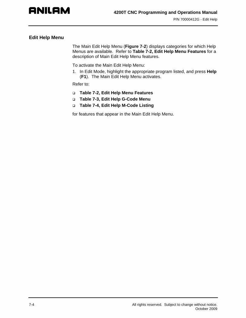
4200T CNC Programming and Operations Manual P/N 70000412G - Edit Help
7-4 All rights reserved. Subject to change without notice. October 2009
Edit Help Menu
The Main Edit Help Menu (Figure 7-2) displays categories for which Help Menus are available. Refer to Table 7-2, Edit Help Menu Features for a description of Main Edit Help Menu features.
To activate the Main Edit Help Menu: 1. In Edit Mode, highlight the appropriate program listed, and press Help
(F1). The Main Edit Help Menu activates.
Refer to:
Table 7-2, Edit Help Menu Features Table 7-3, Edit Help G-Code Menu Table 7-4, Edit Help M-Code Listing
for features that appear in the Main Edit Help Menu.

4200T CNC Programming and Operations Manual P/N 70000412G - Edit Help
All rights reserved. Subject to change without notice. 7-5 October 2009
Table 7-2, Edit Help Menu Features
Feature Description Menu Item Number Use this number to select a menu item. Help Templates In the Edit Help Menu, help templates access
template help menus. (Template help menus access Help Graphic screens containing instructions for inputting move types and canned cycles.)
Move Type Indicates what help template menu is accessed when the template is activated. Help template menus provide move types or Canned Cycles selections that, when activated, provide instructions for inputting code into a program.
Program Listing The program being edited or written. G-Code Listing Lists and describes commonly used G-Codes
(Preparatory Functions). Does not contain a complete listing of G-Codes. Refer to Table 7-3, Edit Help G-Code Menu for applicable G-Codes.
M-Code Listing Lists and describes commonly used M Codes (Miscellaneous Functions). Does not contain a complete listing of M-Codes. Refer to Table 7-4, Edit Help M-Code Listing for applicable M-Codes.
Input Box The CNC inserts the selected commands at the block displayed in the Input Box and displays commands as they are entered by the programmer. NOTE: The block displayed in the Input Box
depends upon the location of the insertion point in the Program Listing when Help (F1) is pressed.
Input Box Displays G-Codes and other commands selected in the Edit Help Menu. The CNC inserts the selected commands at the block displayed in the Input Box. NOTE: The block displayed in the Input Box
depends upon the location of the insertion point in the Program Listing when Help (F1) is pressed.
Soft Keys Use the soft keys to access, select, and accept programming blocks or to exit the Edit Help menus.

4200T CNC Programming and Operations Manual P/N 70000412G - Edit Help
7-6 All rights reserved. Subject to change without notice. October 2009
Table 7-3, Edit Help G-Code Menu
G-Code Label and Description
G4 Dwell. Programs a timed or infinite dwell.
G9 Exact Stop (Single Block). Non-modal exact stop check. Activates exact stop check for a single block.
G22 Stroke Limit. Activates/deactivates software limits.
G24 Set Maximum Spindle Speed. Sets the maximum programmable spindle speed when the CNC is in Constant Surface Speed Mode (G96).
G53 Offset(s) (Coor. Offset) Shifts the location of Absolute Zero to a preset location. The preset location is the specified fixture offset, measured from Machine Home and stored in the Offsets Table.
G61 Exact Stop Mode (Contouring Mode OFF). Modal Exact Stop Check. Activates In-Position Mode.
G64 Contouring Mode (Exact Stop Mode OFF). Modal Contouring Mode. De-activates In-Position Mode.
G65 Macro Call, Single (Non-Modal). Used in a program to call a stored macro. Macros can be entered after the main program (subprogram) or in another file (must use file inclusion to call to active program). In non-modal macro (G67) call, the variables can be changed at each call.
G66 Macro Call, Modal. Used in a program to call a macro. Macros can be entered after the main program (subprogram) or in another file (must use file inclusion to call to active program). In Modal macro (G66) call, the variables will always contain the same values.
G67 Cancel Modal Macro. Cancels a G66 Modal Macro call.
G92 Preset Zero. Shifts the location of Absolute Zero to a preset location. The preset location, measured from Machine Home, is specified in the G92 command.
G96 Constant Surface Speed (CSS). Sets the CNC’s spindle to Constant Surface Speed (CSS). The CNC adjusts the spindle RPM to maintain a constant surface speed.
G97 Constant RPM. Sets the CNC’s spindle speed to the Revolutions per Minute (RPM) mode.

4200T CNC Programming and Operations Manual P/N 70000412G - Edit Help
All rights reserved. Subject to change without notice. 7-7 October 2009
Table 7-4, Edit Help M-Code Listing
M-Code Function
M0 Program stop
M1 Optional program stop
M2 End of program
M3 Spindle ON FWD
M4 Spindle ON REV
M5 Spindle OFF
M8 Coolant ON
M9 Coolant OFF
M30 Jump to new program
M40 Open gear range
M41 First gear range
M42 Second gear range
M43 Third gear range
M98 Call subprogram
M99 End subprogram
M100 Mirror image

4200T CNC Programming and Operations Manual P/N 70000412G - Edit Help
Edit Help Soft Keys Refer to Table 7-5 for a list of the soft keys available in the Main Edit Help Menu.
Table 7-5, Edit Help Soft Keys
Soft Key Label No. Description
(UP) F1 Moves highlight to the next Help Template.
(DOWN) F2 Moves highlight to the previous Help
Template. Text F4 Switches the text shown in the center of the
Edit Help Menu between two choices. The CNC displays either: − the active program and input box, or − instructions for using the Edit Help Menu
Select F5 Selects the highlighted Help Template or G Code choice.
ReEdit F6 When the insertion point is placed on a block containing a Canned Cycle, pressing ReEdit (F6) automatically activates the Help Graphic screen pertaining to the Canned Cycle. Once all the fields have been edited, press Accept (F8).
Abort F7 Deactivates the Edit Help Menu and returns the user to the Program Listing. NOTE: When the Edit Help Menu is deactivated, the CNC saves all accepted edits. The CNC does not save unaccepted edits to the block displayed in the Input Box.
Accept F8 Inserts the block displayed in the Input Box into the program.
Exit F10 Returns the CNC to the Program Listing.
7-8 All rights reserved. Subject to change without notice. October 2009

4200T CNC Programming and Operations Manual P/N 70000412G - Edit Help
Help Template Menu Selecting a help template from the Edit Help Menu activates the Help Template Menu for the selected move type or Canned Cycle. (Refer to Figure 7-3, Sample Help Template Menu). Help Template Menus are available for the move types described in Table 7-6. To activate a help template menu: 1. With the Edit Help Menu active, enter the menu item number, and
press ENTER. The help template menu for the selected item number activates.
Table 7-6, Help Template Menus
Template Description Reference Table
COMPENSATION (Compensated Moves)
Table 7-7, Compensation Help Template Menu
LINES
3
LINES (Line Moves)
Table 7-8, LINES Help Template Menu
ARCS (Arcs)
Table 7-9, ARCS Help Template Menu
RAD/CHAMFER
5
RAD/CHAMFER (Radius or Chamfer Moves)
Table 7-10, RAD/CHAMFER Help Template Menu
MUTIPLE
6
MULTIPLE (Moves Containing Multiple Radius and/or Chamfer Moves)
Table 7-11, MULTIPLE Help Template Menu
THREADING
7
THREADING (Threading Cycles)
Table 7-12, THREADING Help Template Menu
CLEARING
8
CLEARING (Clearing Cycles)
Table 7-13, CLEARING Help Template Menu
(Continued…)
All rights reserved. Subject to change without notice. 7-9 October 2009

4200T CNC Programming and Operations Manual P/N 70000412G - Edit Help
Table 7-6, Help Template Menus (Continued)
Template Description Reference Table
DRILL/TAP (Drill and Tapping Cycles)
Table 7-14, DRILL/TAP Help Template Menu
The following features appear in each of the Help Template Menus:
Menu Item Number You select a menu item for which the appropriate Help Graphic screen will be displayed. NOTE: To select a menu item, press the corresponding number on the keypad, and press ENTER.
Help Templates Menu items containing available move types and Canned Cycles. When selected, these templates activate a Help Graphic screen. (Help Graphic screens contain instructions for inputting commands into the Program Listing.) Help template menus are available for the move types listed in Figure 7-3, Sample Help Template Menu.
On Screen Instructions
Press TEXT (F4) to switch the text displayed in the middle of the screen between on-screen instructions and the active Program Listing. On screen instructions may contain a description of each menu item (template) in the active Help Template Menu or general instructions on using Edit Help.
Input Box The CNC inserts the selected commands at the block displayed in the Input Box and displays commands as they are entered by the programmer.
Soft keys Use the soft keys to access, select, and accept programming blocks or to exit the screen. The Help Template Menus contains many of the same soft keys as the Edit Help Menu, with the following exceptions: The ReEdit (F6) soft key is inactive in the Help Template Menu. The Prev (F9) soft key is active. When the Prev (F9) soft key is activated, the CNC returns to the previous screen.
Modal G-Codes Modal G-Codes do not program actual moves. Use these commands to change the Rapid/Feed Mode, Inch/MM mode, Absolute/Incremental Mode, and Feed Per Revolution/Feed Per Minute Mode.
7-10 All rights reserved. Subject to change without notice. October 2009

4200T CNC Programming and Operations Manual P/N 70000412G - Edit Help
Help Graphic Screens The Help Graphic screens list and give instructions on entering move types and Canned Cycles into the Program Listing.
Refer to Figure 7-4. Help Graphics screens are available for templates listed in Table 7-6, Help Template Menus.
SCALING
Soft Keys
Figure 7-4, Sample Help Graphic Screen To activate a Help Graphics screen: 1. With the Edit Help Menu active, enter the appropriate menu item
number, and press ENTER. (Refer to Figure 7-2, Main Edit Help Menu.) The help template menu for the selected move type or Canned Cycle activates.
From the activated Help Template Menu, enter the appropriate menu item number, and press ENTER. The Help Graphic screen for the selected template activates. It will contain labeled entry fields and a graphic describing the move type or Canned Cycle being programmed.
All rights reserved. Subject to change without notice. 7-11 October 2009

4200T CNC Programming and Operations Manual P/N 70000412G - Edit Help
7-12 All rights reserved. Subject to change without notice. October 2009
The following features are available in the Help Graphic screens:
Menu Item Number Menu items 2 through 9 are inactive in the Help Graphic screen. A new selection can be made when the block for the active Help Graphic screen has been inserted into the Program Listing or canceled.
Help Templates
The Help Templates displayed on the screen remain inactive until the values for the selected move type or Canned Cycle have been inserted into the Program Listing.
Press Exit (F10) to insert the block into the program and return to the Program Listing.
On Screen Instructions
On-screen instructions include a description of the selected menu item (move, G Code or Canned Cycle) being programmed, the entry fields, and graphic pertaining to the selected menu item.
Input Box The CNC inserts the selected commands at the block displayed in the Input Box and displays commands as they are entered by the programmer.
Soft keys Use the soft keys to access, select, and accept programming blocks or to exit the screen. The Help Template Menus contain many of the same soft keys as the Edit Help Menu, with the following exceptions:
The ReEdit (F6) and Text (F4) soft keys are inactive in the Help Graphic screens. The Prev (F9) soft key is active. When the Prev (F9) soft key is activated, the CNC returns to the previous screen.
Modal G-Codes Modal G-Codes do not program actual moves. Use these commands to change the Rapid/Feed Mode, Inch/MM mode, Absolute/Incremental Mode, and Feed Per Revolution/Feed Per Minute Mode.

4200T CNC Programming and Operations Manual P/N 70000412G - Edit Help
All rights reserved. Subject to change without notice. 7-13 October 2009
Using Help Graphic Screens to Enter Program Blocks The Program Editor displays Help Graphic screens for writing and editing program blocks.
When a Help Graphic screen is first displayed, the first entry field is highlighted. Once a field is highlighted, it will accept a value or selection made by the operator. Pressing ENTER advances the highlight to the next entry field. Pressing ENTER from the last entry field closes the block, and adds it to the Program Listing. Pressing the Accept (F8) soft key from any entry field also closes the block, and adds it to the program. Move the highlight from field to field using the ARROW keys. Entry fields can be filled in any order. Pressing the CLEAR key clears the value in the highlighted field.
There are two types of entry fields in a Help Graphic screen:
Required entry fields - These fields contain “0.000” when the Help Graphic screen is first displayed.
Optional entry fields - These fields are completely blank when the Help Graphic screen is first displayed.
Required entry fields cannot be left blank. The value can remain “0.000” (zero), if appropriate. If a required entry field is left blank, the CNC still writes the block, but when the block is executed, it holds the machine, and generates an error message.
Optional entry fields do not require a value. When left blank, a default value or position is usually assumed.
The operator must remember to enter decimal points and negative signs where needed. The CNC assumes a positive value if no negative sign is keyed in.
Use the (+/-) key, to insert a negative sign. The (+/-) key is also used to switch the selection in entry fields that offer specific choices.

4200T CNC Programming and Operations Manual P/N 70000412G - Edit Help
Available Help Graphic Screens Help Graphic Screens are available for each of the templates shown and described in Table 7-7. The table shows the Edit Help Menu Templates and Template Menus. The input labels and entry fields are defined for each move type available in Edit Help.
NOTE: All examples used in this manual refer to machines with a front tool post orientation.
Table 7-7, Compensation Help Template Menu
COMPENSATION Templates and Parameters Move Description
COMP OFF
2 G40 Select the COMP OFF template, and press ENTER automatically inserts the G40 command into the Input Box.
No move programmed. Tool Nose Radius Compensation canceled.
G41
Select the COMP LEFT template, and press ENTER automatically inserts the G41 command into the Input Box.
No move programmed. Tool Nose Radius Compensation, left of path, activated.
G42
Select the COMP LEFT template, and press ENTER automatically inserts the G42 command into the Input Box.
No move programmed. Tool Nose Radius Compensation, right of path, activated.
7
SCALING
G72 Select SCALING Template, and press ENTER.
Scales dimensional data (X/Z) following the command by the scale factor specified.
7-14 All rights reserved. Subject to change without notice. October 2009

4200T CNC Programming and Operations Manual P/N 70000412G - Edit Help
Table 7-8, LINES Help Template Menu
LINES
3 LINES Templates and Parameters Move Description
Z End Pt.: Z endpoint
CNC moves in a straight line along the Z-axis.
X
3
X End Pt.: X endpoint
CNC moves in a straight line along the X-axis.
X/Z
4
X End Pt.: X endpoint Z End Pt.: Z endpoint
CNC moves along a vectored path from the current location to the X, Z endpoint.
Angle: B, angle measured from the Z-axis (3 o’clock equals 0 degrees) Z End Pt.: Z endpoint
CNC moves along a vectored path from the current location to the endpoint.
ANGLE/X
6
Angle: B, angle measured from the Z-axis (3 o’clock equals 0 degrees) X End Pt.: X endpoint
CNC moves along a vectored path from the current location to the endpoint.
(Continued…)
All rights reserved. Subject to change without notice. 7-15 October 2009

4200T CNC Programming and Operations Manual P/N 70000412G - Edit Help
Table 7-8, LINES Help Template Menu (Continued)
LINES
3 LINES Templates and Parameters Move Description
ANGLE/RADIUS
7
Angle: B, angle measured from the Z-axis (3 o’clock equals 0 degrees). Radius: Q, distance from the centerpoint of an arc to the circumference.
CNC moves along a vectored path from the current location to the endpoint.
RADIUS/Z
8
Radius: Q, distance from the centerpoint of an arc to the circumference. Z End Pt.: Z endpoint.
CNC moves along a vectored path from the current location to the endpoint.
RADIUS/X
9
Radius: Q, distance from the centerpoint of an arc to the circumference. X End Pt.: X endpoint.
CNC moves along a vectored path from the current location to the endpoint.
7-16 All rights reserved. Subject to change without notice. October 2009
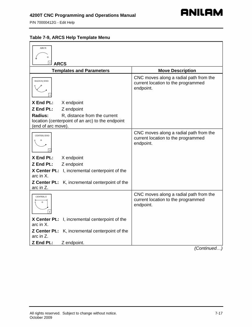
4200T CNC Programming and Operations Manual P/N 70000412G - Edit Help
Table 7-9, ARCS Help Template Menu
ARCS Templates and Parameters Move Description
RADIUS/END
2
X End Pt.: X endpoint Z End Pt.: Z endpoint Radius: R, distance from the current location (centerpoint of an arc) to the endpoint (end of arc move).
CNC moves along a radial path from the current location to the programmed endpoint.
CENTER/END
3
X End Pt.: X endpoint Z End Pt.: Z endpoint X Center Pt.: I, incremental centerpoint of the arc in X. Z Center Pt.: K, incremental centerpoint of the arc in Z.
CNC moves along a radial path from the current location to the programmed endpoint.
X Center Pt.: I, incremental centerpoint of the arc in X. Z Center Pt.: K, incremental centerpoint of the arc in Z. Z End Pt.: Z endpoint.
CNC moves along a radial path from the current location to the programmed endpoint.
(Continued…)
All rights reserved. Subject to change without notice. 7-17 October 2009

4200T CNC Programming and Operations Manual P/N 70000412G - Edit Help
Table 7-9, ARCS Help Template Menu (Continued)
ARCS Templates and Parameters Move Description
CENTER/X
5
X Center Pt.: I, incremental centerpoint of the arc in X. Z Center Pt.: K, incremental centerpoint of the arc in Z. X End Pt.: X endpoint.
CNC moves along a radial path from the current location to the programmed endpoint.
CENTER/ANGLE
6
X Center Pt.: I, centerpoint of the arc in X. Z Center Pt.: K, centerpoint of the arc in Z. Angle: B, angle measured from the Z-axis (3 o’clock equals 0 degrees).
CNC moves along a radial path from the current location to the programmed endpoint.
ARC/LINE
7
Radius: Q, distance from the centerpoint of the arc to the circumference. Angle: B, angle measured from the Z-axis (3 o’clock equals 0 degrees). X End Pt.: X endpoint. Z End Pt.: Z endpoint.
The CNC performs an ARC move to the tangent point of the LINE intersection, and then moves at the specified angle to the endpoints.
8
Angle: B, angle measured from the Z-axis (3 o’clock equals 0 degrees). Radius: Q, distance from the centerpoint of an arc to the circumference. X End Pt.: X endpoint. Z End Pt.: Z endpoint.
The CNC performs a LINE move to the tangent point of the ARC intersection, and then moves at the specified radius to the endpoints.
7-18 All rights reserved. Subject to change without notice. October 2009

4200T CNC Programming and Operations Manual P/N 70000412G - Edit Help
Table 7-9, ARCS Help Template Menu (Continued)
ARCS Templates and Parameters Move Description
ARC/ARC
9
R1 Center X: I, centerpoint of the first arc in X. R1 Center Z: K, centerpoint of the first arc in Z. R2 Center X: I, centerpoint of the second arc in X. R2 Center Z: K, centerpoint of the second arc in Z. X End Pt.: X endpoint. Z End Pt.: Z endpoint.
CNC performs an arc move into another arc move. The first arc ends and the second arc begins at the point where the two arcs are tangent.
ELLIPSE
GO5
X End Pt.: X endpoint. Z End Pt.: Z endpoint. X Center Pt.: I, centerpoint of the arc in X. Z Center Pt.: K, centerpoint of the arc in Z. Half Width: A, half the width in X of the entire ellipse. Half Length: B, half the length in Z of the entire ellipse. CCW+, CW -: L, direction of tool travel. +1 for counterclockwise and -1 for clockwise.
CNC moves along an elliptical path from the current location to the programmed endpoint. This path could be a whole or partial ellipse in a clockwise or counterclockwise direction.
All rights reserved. Subject to change without notice. 7-19 October 2009

4200T CNC Programming and Operations Manual P/N 70000412G - Edit Help
Table 7-10, RAD/CHAMFER Help Template Menu
RAD/CHAMFER
5 RAD/CHAMFER
Templates and Parameters Move Description
RADIUS
2
X Midpoint: X intersection point of two lines. Z Midpoint: Z intersection point of two lines. Radius: Q, radius of arc tangent to two lines. X End Pt.: X endpoint. Z End Pt.: Z endpoint.
The CNC performs a LINE move to the intersecting ARC, moves around the arc, and then moves along the second LINE to the specified endpoints.
CHAMFER
3
X Midpoint: X intersection point of two lines. Z Midpoint: Z intersection point of two lines. Chamfer: Distance from the XZ midpoint to the start/end of the Chamfer move. X End Pt.: Endpoint in X. Z End Pt.: Endpoint in Z.
The CNC performs a LINE move to the intersecting CHAMFER, moves across the chamfer, and then moves along the second LINE to the specified endpoints.
CORNER RAD
4G59 G59
Radius: R, radius of arc used to round off each corner. NOTE: Possible in non-tangent line to line, line to arc, arc to line, and arc to arc moves.
The CNC performs an automatic corner rounding (where practical) at all intersecting elements (LINES, ARCS) with the specified radius. G59 (activate corner rounding) should be programmed on the block prior to the first required corner radius. G60 (cancel corner rounding) should be programmed on the block immediately following the last required corner radius. NOTE: Corner Rounding cannot be used in conjunction with Blue Print Programming (multiple moves programmed on the same block).
(Continued…)
7-20 All rights reserved. Subject to change without notice. October 2009

4200T CNC Programming and Operations Manual P/N 70000412G - Edit Help
Table 7-10, RAD/CHAMFER Help Template Menu (Continued)
RAD/CHAMFER
5 RAD/CHAMFER
Templates and Parameters Move Description
CORNER CHAMF
5G59
Chamfer: E, radius of chamfer used to round off each corner. NOTE: Possible in non-tangent line to line, line to arc, arc to line, and arc to arc moves.
The CNC performs an automatic corner chamfer (where practical) at all intersecting elements (LINES, ARCS). G59 (activate corner chamfering) should be programmed on the block prior to the first required corner chamfer. G60 (cancel corner chamfering) should be programmed on the block immediately following the last required corner chamfer. NOTE: Corner Chamfering cannot be used in conjunction with Blue Print Programming (multiple moves programmed on the same block).
All rights reserved. Subject to change without notice. 7-21 October 2009

4200T CNC Programming and Operations Manual P/N 70000412G - Edit Help
Table 7-11, MULTIPLE Help Template Menu
MUTIPLE
6 MULTIPLE Templates and Parameters Move Description
DEFINITION
2
First Angle: B, angle measured from the Z-axis (3 o’clock equals 0 degrees). Second Angle: B, angle measured from the Z-axis (3 o’clock equals 0 degrees). X End Pt.: Endpoint in X. Z End Pt.: Endpoint in Z.
The CNC performs a LINE move along the First Angle to the intersection of the Second Angle, and then continues along the Second Angle to the specified endpoints.
RADIUS
3 First Angle: B, angle measured from the Z-axis (3 o’clock equals 0 degrees). Radius: Q, radius of intersecting arc. Second Angle: B, angle measured from the Z-axis (3 o’clock equals 0 degrees). X End Pt.: Endpoint in X. Z End Pt.: Endpoint in Z.
The CNC performs a LINE move along the First Angle to the intersecting ARC, moves around the arc, and then moves along the Second Angle to the specified endpoint.
CHAMFER
4 First Angle: B, angle measured from the Z-axis (3 o’clock equals 0 degrees). Chamfer: E, length of intersecting chamfer. Second Angle: B, angle measured from the Z-axis (3 o’clock equals 0 degrees). X End Pt.: Endpoint in X. Z End Pt.: Endpoint in Z.
The CNC performs a LINE move along the First Angle to the intersecting CHAMFER, moves across the chamfer, and then moves along the Second Angle to the specified endpoints.
(Continued…)
7-22 All rights reserved. Subject to change without notice. October 2009

4200T CNC Programming and Operations Manual P/N 70000412G - Edit Help
Table 7-11, MULTIPLE Help Template Menu (Continued)
MUTIPLE
6 MULTIPLE Templates and Parameters Move Description
5
RAD/RAD
1st Angle: B, angle measured from the Z-axis (3 o’clock equals 0 degrees). 1st Radius: Q, radius of arc tangent to 1st and 2nd Angle. 2nd Angle: B, angle measured from the Z-axis (3 o’clock equals 0 degrees). X Mid Pt.: Midpoint in X. Z Mid Pt.: Midpoint in Z. 2nd Radius: Q, radius of arc tangent to 2nd Angle and endpoints. X End Pt.: Endpoint in X. Z End Pt.: Endpoint in Z.
The CNC performs a LINE move along the 1st Angle to the intersecting arc. After completing the arc, the CNC moves along the 2nd Angle to the intersection of the 2nd arc. After completing the 2nd arc, the CNC moves to the specified endpoints.
(Continued…)
All rights reserved. Subject to change without notice. 7-23 October 2009
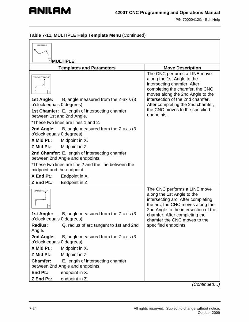
4200T CNC Programming and Operations Manual P/N 70000412G - Edit Help
Table 7-11, MULTIPLE Help Template Menu (Continued)
MUTIPLE
6 MULTIPLE Templates and Parameters Move Description
CHAMF/CHAMF
6
1st Angle: B, angle measured from the Z-axis (3 o’clock equals 0 degrees). 1st Chamfer: E, length of intersecting chamfer between 1st and 2nd Angle. *These two lines are lines 1 and 2. 2nd Angle: B, angle measured from the Z-axis (3 o’clock equals 0 degrees). X Mid Pt.: Midpoint in X. Z Mid Pt.: Midpoint in Z. 2nd Chamfer: E, length of intersecting chamfer between 2nd Angle and endpoints. *These two lines are line 2 and the line between the midpoint and the endpoint. X End Pt.: Endpoint in X. Z End Pt.: Endpoint in Z.
The CNC performs a LINE move along the 1st Angle to the intersecting chamfer. After completing the chamfer, the CNC moves along the 2nd Angle to the intersection of the 2nd chamfer. After completing the 2nd chamfer, the CNC moves to the specified endpoints.
RAD/CHAMF
7
1st Angle: B, angle measured from the Z-axis (3 o’clock equals 0 degrees). Radius: Q, radius of arc tangent to 1st and 2nd Angle. 2nd Angle: B, angle measured from the Z-axis (3 o’clock equals 0 degrees). X Mid Pt.: Midpoint in X. Z Mid Pt.: Midpoint in Z. Chamfer: E, length of intersecting chamfer between 2nd Angle and endpoints. End Pt.: endpoint in X. Z End Pt.: endpoint in Z.
The CNC performs a LINE move along the 1st Angle to the intersecting arc. After completing the arc, the CNC moves along the 2nd Angle to the intersection of the chamfer. After completing the chamfer the CNC moves to the specified endpoints.
(Continued…)
7-24 All rights reserved. Subject to change without notice. October 2009

4200T CNC Programming and Operations Manual P/N 70000412G - Edit Help
Table 7-11, MULTIPLE Help Template Menu (Continued)
MUTIPLE
6 MULTIPLE Templates and Parameters Move Description
CHAMF/RAD
8
1st Angle: B, angle measured from the Z-axis (3 o’clock equals 0 degrees). Chamfer: E, length of intersecting chamfer between 1st and 2nd Angle. *These are lines 1 and 2. 2nd Angle: B, angle measured from the Z-axis (3 o’clock equals 0 degrees). X Mid Pt.: Midpoint in X. Z Mid Pt.: Midpoint in Z. Radius: Q, radius of arc tangent to 2nd Angle and endpoints. X End Pt.: Endpoint in X. Z End Pt.: Endpoint in Z.
The CNC performs a LINE move along the 1st Angle to the intersecting chamfer. After completing the chamfer, the CNC moves along the 2nd Angle to the intersection of the arc. After completing the arc the CNC moves to the specified endpoints.
All rights reserved. Subject to change without notice. 7-25 October 2009

4200T CNC Programming and Operations Manual P/N 70000412G - Edit Help
Table 7-12, THREADING Help Template Menu
THREADING
7 THREADING Templates and Parameters Move Description
UNI-DIRECT.
G83 2 G83 Longitudinal Uni-Directional Threading Entered Values Length: Z, incremental distance in the Z-axis from Tool start position to finish point (length of threading pass). First Cut: C, incremental depth of the first cut (depth of cut per side for first pass). Does not include B parameter. Thread Depth: D, incremental depth of the thread (depth of thread per side). Does not include B parameter. Default: Pitch x 0.6134 (60 degree thread). Thread Angle: A, thread angle, 60 degrees for standard threads. Default: 0 degrees for a straight plunge thread. Z Pullout: R, incremental Z-axis pullout distance. Creates a 2-axis pullout move. Default: 0 causes the tool to pullout at 90 degrees to the threading pass. Taper X: X, distance moved in the X-axis during a threading pass. Default: 0 straight thread. Taper Angle: V, Angle of tapered thread. Default: 0 NOTE: When programming a tapered thread, use X or V parameters, but not both. X Standoff: B, distance in the X-axis from the tool tip to the work diameter per side. Default: Inch = 0.1 Outside Diameter Default: Inch = -0.1 Inside Diameter Default: MM = 2 Outside Diameter Default: MM = -2 Inside Diameter Tool must be positioned the Standoff distance away from the diameter in the block prior to the threading Canned Cycle. Num. Starts: W, used to program the number of starts in a multiple start thread. Default: 1 (Single start thread)
The G83 cycle creates a longitudinal thread along the Z-axis using multiple passes to reach full thread depth. The CNC moves from the X standoff (B) to the diameter of the work, plus the first depth of cut (C) and completes the first pass. The tool returns to the start point, and subsequent passes are taken at reducing depths of cut until the completed depth is reached. The number of passes necessary to complete a thread is calculated by the CNC based on the Thread Depth (D), and the depth of the first pass (C). The thread may be cut by a plunge motion (A=0), or by a compound motion (A=Angle of cutting tool*.) A number of finish passes (S=# of passes taken at final depth) may be specified. Default: 1 R creates a 2-axis pullout move. The tool moves the distance programmed (R) in the Z-axis while retracting to the B standoff in the X-axis. If the taper angle (V) or distance (X) is specified the threading passes are completed at specified taper. The W parameter specifies the number of thread starts. A second use for the W parameter (programming a W-1) will cause all threading passes to be performed at the same depth of cut. D divided by C. Threads are normally cut in reducing depths of cut. *In the G83 cycle (uni-directional threading) if the A parameter is programmed the cycle will performed the passes using a compound cutting motion. The tool enters the thread on an angle (described by the A parameter), and cuts only on the leading edge of the tool.
7-26 All rights reserved. Subject to change without notice. October 2009

4200T CNC Programming and Operations Manual P/N 70000412G - Edit Help
TPI: E, Threads per inch. Used in Inch programming. Lead: F, pitch (single pass threading) or amount of travel in Z per revolution (multi-pass threading). Used in MM programming. NOTE: Use E or F, but not both. # Fini. Pass: S, number of passes at final depth. Default: 1.
BI-DIRECT.
G84 3
G84 Longitudinal Bi-Directional Threading TPI: E, Threads per inch. Used in Inch programming. Lead: F, pitch (single pass threading) or amount of travel in Z per revolution (multi-pass threading). Used in MM programming. NOTE: Use E or F, but not both. Length: Z, incremental distance in the Z-axis from Tool start position to finish point (length of threading pass). First Cut: C, incremental depth of the first cut (depth of cut per side for first pass). (Does not include B parameter). Thread Depth: D, incremental depth of the thread (depth of thread per side). (Does not include B parameter.) Default: Pitch x 0.6134 (60 degree thread). Thread Angle: A, thread angle, 60 degrees for standard threads. Default: 0 degrees for a straight plunge thread. # Fini. Pass: S, number of passes at final depth. Default: 1. Z Pullout: R, incremental Z-axis pullout distance. Creates a 2-axis pullout move. Default: 0 causes the tool to pullout at 90 degrees to the threading pass. X Standoff: B, distance in the X-axis from the tool tip to the work diameter per side. Default: Inch = 0.1 Outside Diameter Default: Inch = -0.1 Inside Diameter. Default: MM = 2 Outside Diameter Default: MM = -2 Inside Diameter (Tool must be positioned the Standoff distance away from the diameter in the block prior to the
The G84 cycle creates a longitudinal thread along the Z-axis using multiple passes to reach full thread depth. The CNC moves from the X standoff (B) to the diameter of the work, plus the first depth of cut (C), and completes the first pass. The tool returns to the start point, and subsequent passes are taken at reducing depths of cut until the completed depth is reached. The number of passes necessary to complete a thread is calculated by the CNC based on the Thread Depth (D), and the depth of the first pass (C). The thread may be cut by a plunge motion (A=0), or by a compound motion (A=Angle of cutting tool*.) A number of finish passes (S=# of passes taken at final depth) may be specified. Default: 1 R creates a 2-axis pullout move. The tool moves the distance programmed (R) in the Z-axis while retracting to the B standoff in the X-axis. *In the G84 cycle (uni-directional threading) if the A parameter is programmed, the cycle will perform the passes using a compound cutting motion. The tool enters the thread on an angle (described by the A parameter), and cuts alternating passes on the leading and trailing edges of the tool.
All rights reserved. Subject to change without notice. 7-27 October 2009

4200T CNC Programming and Operations Manual P/N 70000412G - Edit Help
threading Canned Cycle. Num. Starts: W, used only in multiple pass threading, the number of staggered starts used to reach depth. Default: 1. NOTE: Specifying the Num. of Starts changes the way the CNC interprets all other threading variables.
UNI-DIRECT.
G85 4
G85 Radial Uni-directional Threading TPI: E, Threads per inch. Used in Inch programming. Lead: F, pitch (single pass threading) or amount of travel in X per revolution (multi-pass threading). Used in MM programming. NOTE: Use E or F, but not both. Length: X, incremental distance in the X-axis from Tool start position to finish point (length of threading pass). First Cut: C, incremental depth of the first cut (depth of cut for first pass). (Does not include B parameter.) Thread Depth: D, incremental depth of the thread (depth of thread). (Does not include B parameter) Default: Pitch x 0.6134 (60 degree thread). Thread Angle: A, thread angle, usually 60 degrees. Default: 0 degrees for a straight plunge thread. # Fini. Pass: S, number of passes at final depth. Default: 1. X Pullout: R, incremental X-axis pullout distance. Creates a 2-axis pullout move. Default: 0, causes the tool to pullout at 90 degrees to the threading pass. Taper Z: Z, distance moved in the Z-axis during a threading pass. Default: 0 straight thread. Taper Angle: V, Angle of tapered thread. Default: 0. NOTE: When programming a tapered thread use Z or V parameters, but not both. Z Standoff: B, distance in the Z-axis from the tool tip to the work face. Default: Inch = 0.1 Default: MM = 2. (Tool must be positioned the Standoff distance away from the face in the block prior to the threading Canned Cycle.)
The G85 cycle creates a radial thread along the X-axis using multiple passes to reach full thread depth. The CNC moves from the Z standoff (B) to the face of the work, plus the first depth of cut (C), and completes the first pass. The tool returns to the start point, and subsequent passes are taken at reducing depths of cut until the completed depth is reached. The number of passes necessary to complete a thread is calculated by the CNC based on the Thread Depth (D), and the depth of the first pass (C). The thread may be cut by a plunge motion (A=0), or by a compound motion (A=Angle of cutting tool*.) A number of finish passes (S=# of passes taken at final depth) may be specified. Default: 1 R creates a 2-axis pullout move. The tool moves the distance programmed (R) in the X-axis while retracting to the B standoff in the Z-axis. If the taper angle (Z) or distance (V) is specified the threading passes are completed at specified taper. The W parameter specifies the number of thread starts. A second use for the W parameter (programming a W-1) will cause all threading passes to be performed at the same depth of cut. D divided by C. Threads are normally cut in reducing depths of cut. *In the G85 cycle (uni-directional threading) if the A parameter is programmed, the cycle will perform the passes using a compound cutting motion. The tool enters the thread on an
7-28 All rights reserved. Subject to change without notice. October 2009

4200T CNC Programming and Operations Manual P/N 70000412G - Edit Help
Num. Starts: W, used to program the number of starts in a multiple start thread. Default: 1 (Single start thread).
angle (described by the A parameter), and cuts only on the leading edge of the tool.
BI-DIRECT.
G86 5
G86 Radial Bi-directional Threading TPI: E, Threads per inch. Used in Inch programming. Lead: F, pitch (single pass threading) or amount of travel in X per revolution (multi-pass threading). Used in MM programming. NOTE: Use E or F, but not both. Length: X, incremental distance in the X-axis from Tool start position to finish point (length of threading pass). First Cut: C, incremental depth of the first cut (depth of cut for first pass). (Does not include B parameter). Thread Depth: D, incremental depth of the thread (depth of thread). (Does not include B parameter) Default: Pitch x 0.6134 (60 degree thread). Thread Angle: A, thread angle, 60 degrees for standard threads. Default: 0 degrees for a straight plunge thread. # Fini. Pass: S, number of passes at final depth. Default: 1. X Pullout: R, incremental X-axis pullout distance. Creates a 2-axis pullout move. Default: 0 causes the tool to pullout at 90 degrees to the threading pass. Z Standoff: B, distance in the Z-axis from the tool tip to the work face. Default: Inch = 0.1 Default: MM = 2 Tool must be positioned the Standoff distance away from the face in the block prior to the threading Canned Cycle. Num. Starts: W, used only in multiple pass threading, the number of staggered starts used to reach depth. Default: 1. NOTE: Specifying Num. of Starts changes the way the CNC interprets
The G86 cycle creates a radial thread along the X-axis using multiple passes to reach full thread depth. The CNC moves from the Z standoff (B) to the face of the work, plus the first depth of cut (C), and completes the first pass. The tool returns to the start point, and subsequent passes are taken at reducing depths of cut until the completed depth is reached. The number of passes necessary to complete a thread is calculated by the CNC based on the Thread Depth (D), and the depth of the first pass (C). The thread may be cut by a plunge motion (A=0), or by a compound motion (A=Angle of cutting tool*.) A number of finish passes (S=# of passes taken at final depth) may be specified. Default: 1 R creates a 2-axis pullout move. The tool moves the distance programmed (R) in the X-axis while retracting to the B standoff in the Z-axis. *In the G86 cycle (Bi-directional threading) if the A parameter is programmed, the cycle will perform the passes using a compound cutting motion. The tool enters the thread on an angle (described by the A parameter), and cuts alternating passes on the leading and trailing edges of the tool.
All rights reserved. Subject to change without notice. 7-29 October 2009

4200T CNC Programming and Operations Manual P/N 70000412G - Edit Help
Table 7-12, THREADING Help Template Menu (Continued)
THREADING
7 THREADING Templates and Parameters Move Description
TAPPING
G87 6
G87 Tapping Cycle Finish Depth: Z, Absolute depth of thread. Z Start: R, initial start position, in rapid. Feed./Pitch: F, feed in Inches per Revolution. Z Return: P, absolute Z return position.
The CNC feeds the tap from the initial start position (R) into a pre-drilled hole along the Z-axis. When the finish depth (Z) is reached, the spindle stops and reverses direction. The tap is then retracted in the Z-axis at the same feedrate and spindle speed.
THREADING
G33 8
G33 Single-pass Thread Cutting X End Pt.: X end point. Z End Pt.: Z end point. TPI: E, Threads per inch. Used in Inch programming. Lead: F, pitch. Used in MM programming. NOTE: Use E or F, but not both. X Pullout: A, incremental X retract distance. Z Pullout: C, incremental Z retract distance.
The G33 command creates a longitudinal, radial or tapered thread using single pass threading. To obtain multiple passes use the G33 command in a Loop. The tool must be positioned at the first cutting depth prior to initiating the G33 command. For straight longitudinal threading, enter only the Z endpoint. For straight radial threading enter only the X endpoint. For tapered threading, enter both the X and Z endpoints. G33 command gives only one threading pass to the X, Z, or XZ endpoints. The tool retracts from the threading pass using the X, Z, or XZ pullout distances given by the A and/or C parameters. If no pullout dimensions are stated, the tool retracts at 90 degrees to the threading pass.
7-30 All rights reserved. Subject to change without notice. October 2009

4200T CNC Programming and Operations Manual P/N 70000412G - Edit Help
Table 7-13, CLEARING Help Template Menu
CLEARING
8 CLEARING Templates and Parameters Move Description
AREA CLR TURN
2G73 G73 Area Clearance (Turn) Cycle
Input Sub #: W, subprogram number in which the part profile is programmed. The subprogram is programmed after the end of the main program. Depth/Pass: A, depth of material in X to be removed (per side) on each roughing pass. X Finish Stk: R, amount of material to remain after roughing for a finish pass (X-axis). Z Finish Stk: S, amount of material to remain after roughing, for a finish pass (Z-axis). Finish Pass: C=0 (no finish pass taken) C=1 (a finish contour pass will be taken after the roughing passes are completed). OD=1, ID=0: B, 1 (completes passes along the Z-axis, away from the centerline) or 0 (completes passes along the Z-axis, toward the centerline). Required. Undercut: P, Use value of 1 if there are undercuts in the profile to be rough/finish cut. Leave unassigned if no undercuts are used. X In Feed.: I, plunge feedrate. Rough Feed.: J, feedrate for the roughing pass. Finish Feed.: K, feedrate for the finish pass.
The G73 Area Clearance Cycle rough turns a work piece to a profile described in a subprogram. The subprogram is named by a subprogram number using the O (letter O) parameter followed by a number 1–999. The W parameter in the G73 cycle calls the subprogram number. Roughing passes are made along the Z-axis, and may be either an OD profile (B=1) or an ID profile (B=0), the feedrate for the roughing passes is set by the (J) parameter. The amount of material (stock) to be removed by a finish pass is described by the parameters (R) for the X-axis, and (S) for the Z-axis. A finish feedrate may also be described by the (K) parameter.
(Continued…)
All rights reserved. Subject to change without notice. 7-31 October 2009

4200T CNC Programming and Operations Manual P/N 70000412G - Edit Help
Table 7-13, CLEARING Help Template Menu (Continued)
CLEARING
8 CLEARING Templates and Parameters Move Description
AREA CLR FACE
3G74 G74 Area (Face) Clearance Cycle Input Sub #: W, subprogram number in which the part profile is programmed. The subprogram is programmed after the end of the main program. Depth/Pass: A, depth of material in Z to be removed on each roughing pass. X Finish Stk: R, amount of material to remain after roughing for a finish pass (X-axis). Z Finish Stk: S, amount of material to remain after roughing for a finish pass (Z-axis). Finish Pass: C=0 (no finish pass taken) C=1 (a finish contour pass will be taken after the roughing passes are completed). OD=1, ID=0: B=1, (completes roughing passes in the X-axis towards the part centerline). B=0, (completes roughing passes in the X-axis away from the part centerline). Undercut: P, Use value of 1 if there are undercuts in the profile to be rough/finish cut. Leave unassigned if no undercuts are used. X In Feed.: I, plunge feedrate. Rough Feed: J, feedrate for roughing passes. Finish Feed: K, feedrate for finish pass.
The G74 Area Clearance Cycle rough faces a work piece to a profile described in a subprogram. The subprogram is named by a subprogram number using the O (letter O) parameter followed by a number 1–999. The W parameter in the G74 cycle calls the subprogram number. Roughing passes are made along the X-axis, and may be either toward part centerline (B=1) or away from part centerline (B=0), the feedrate for the roughing passes is set by the (J) parameter. The amount of material (stock) to be removed by a finish pass is described by the parameters (R) for the X-axis, and (S) for the Z-axis. A finish feedrate may also be described by the (K) parameter.
LONGITUDINAL
G76 6
G76 Rough Turning Cycle Total Length: Z, incremental Z distance from start to finish (length). Total Depth: X, incremental depth of material in X to be removed per side. (Excludes B standoff).
The G76 longitudinal cycle removes stock material along the Z-axis in a series of passes. The tool must be positioned appropriately (starting OD + 0.1” / 2mm per side for OD roughing, and starting ID -0.1” / -2mm per for ID roughing) prior to the canned cycle. The CNC calculates both the depth and number of passes required to rough turn the workpiece using the programmed parameters. The actual depth of each pass
7-32 All rights reserved. Subject to change without notice. October 2009

4200T CNC Programming and Operations Manual P/N 70000412G - Edit Help
Depth/Pass: C, maximum incremental depth of cut per side for each pass. Pull Out: A, incremental distance in Z from start position to beginning of pull out. X Standoff: B, incremental X standoff distance from part diameter per side. Default: Inch OD = 0.1 Default: Inch ID = -0.1Default: MM OD = 2 Default: MM ID = -2 (Tool must be positioned the Standoff distance away from the diameter in the block prior to the G76 Canned Cycle). Pull In: D, incremental distance in Z from start position to the end of pull in. Tool Angle: E, rear angle of tool in reference to positive X direction. Must be a negative value.
will not exceed the maximum depth of cut (C). The rear angle of the tool (E) is checked against the angle of the pull in move to avoid interference. If the tool cannot cut the angle due to interference, an error message will be generated. G76 can be used for either OD or ID roughing, all parameters are incremental and sign (+ or -) sensitive. The G76 is a roughing cycle only, and no finish pass completed. If a finish pass is required, it must be programmed separately. Tool Nose Compensation is not supported in the G76 canned cycle.
RADIAL
G77 7
G77 Rough Turning Cycle (Facing, Back Facing) Total Length: X, incremental X distance from start to finish (length). Total Depth: Z, incremental depth of material in Z to be removed. (Excludes B standoff). Depth/Pass: C, maximum incremental depth of cut per pass. Pull Out: A, incremental distance in X from start position to beginning of pull out. Z Standoff: B, incremental Z standoff distance from part face. Default: Inch = 0.1 Default: MM OD = 2 (Tool must be positioned the Standoff distance away from the face in the block prior to the G77 Canned Cycle). Pull In: D, incremental distance in X from start position to the end of pull in. Tool Angle: E, incremental top angle of tool, referenced to the positive Z direction (Z-axis to trailing edge of tool). Must be a positive value.
The G77 Radial cycle removes stock material along the X-axis in a series of passes. The tool must be positioned appropriately (0.1” / 2mm from the face) prior to the canned cycle. The CNC calculates both the depth and number of passes required to rough face the workpiece using the programmed parameters. The actual depth of each pass will not exceed the maximum depth of cut (C). The rear angle of the tool (E) is checked against the angle of the pull in move to avoid interference. If the tool cannot cut the angle due to interference an error message will be generated. All G77 parameters are incremental and sign (+ or -) sensitive. The G77 is a roughing cycle only, and no finish pass is completed. If a finish pass is required, it must be programmed separately. Tool Nose Compensation is not supported in the G77 canned cycle.
(Continued…)
All rights reserved. Subject to change without notice. 7-33 October 2009

4200T CNC Programming and Operations Manual P/N 70000412G - Edit Help
Table 7-13, CLEARING Help Template Menu (Continued)
CLEARING
8 CLEARING Templates and Parameters Move Description
LON'L GROOVE
G81 9 G81 Longitudinal (Diameter) Grooving Cycle Total Length: Z, total incremental length of groove. Total Depth: X, incremental depth of groove per side (excludes B standoff). Tool Width: W, tool width. X Standoff: B, incremental X standoff distance from part diameter per side. Default: Inch OD = 0.1 Default: Inch ID = -0.1Default: MM OD = 2 Default: MM ID = -2 (Tool must be positioned the Standoff distance away from the diameter in the block prior to the G81Canned Cycle). Dwell time: D, dwell time at bottom of the groove, in seconds.
The G81 cycle creates a groove along the Z-axis using the length (Z), and depth (X) parameters. The cycle automatically compensates for the width of the grooving tool. Prior to the cycle the tool must be positioned to the standoff position (0.1” / 2mm) from the diameter of the workpiece. When the tool reaches the total depth (X), it will dwell for the time programmed in parameter D, and then retract. If no dwell is programmed the tool will retract immediately. The CNC calculates the required number of grooving cuts and the width of the passes from the total length (Z). The tool returns to the starting coordinates after completion of the cycle.
G82
RAD'L GROOVE
G82 Radial (Facing) Grooving Cycle Total Length: X, total incremental length of groove. Total Depth: Z, incremental depth of groove (excludes B standoff). Tool Width: W, tool width. Z Standoff: B, incremental Z standoff distance from part face. Default: Inch = 0.1 Default: MM = 2 (Tool must be positioned the Standoff distance away from the face in the block prior to the G81Canned Cycle.) Dwell time: D, dwell time at bottom of the groove, in seconds.
The G82 cycle creates a groove along the X-axis using the length (X), and depth (Z) parameters. The cycle automatically compensates for the width of the grooving tool. Prior to the cycle the tool must be positioned to the standoff position (0.1” / 2mm) from the face of the workpiece. When the tool reaches the total depth (Z), it will dwell for the time programmed in parameter D, and then retract. If no dwell is programmed, the tool will retract immediately. The CNC calculates the required number of grooving cuts and the width of the passes from the total length (X). The tool returns to the starting coordinates after completion of the cycle.
7-34 All rights reserved. Subject to change without notice. October 2009

4200T CNC Programming and Operations Manual P/N 70000412G - Edit Help
Table 7-14, DRILL/TAP Help Template Menu
DRILL/TAP
9 DRILL/TAP Templates and Parameters s Move Description
PECKING
G78 2 G78 Peck Drilling Cycle Finish Depth: Z, Absolute depth of hole Z Start: R, Initial start position. Feedrate: F, feed in Inches per revolution Max Peck: I, incremental maximum depth per peck. Z Return: P, Absolute Z return position.
The Pecking cycle drills a hole using a pecking action. The depth of each peck remains the same, and therefore, this cycle should be used for relatively shallow holes. The CNC drills from the initial start position (R) into the workpiece to the calculated maximum peck depth, and then retracts from the hole to clear chips. The cycle, at a rapid feedrate, returns the drill to +0.01” from the previous hole depth, and feeds to the next peck position. The pecking continues until the Finish Depth (Z) is reached at which point the CNC will return the tool to the initial starting position, or to the (P) parameter if programmed.
CHIP BREAK
G79 3 G79 Chip Break Cycle Finish Depth: Z, Absolute depth of hole Z Start: R, Initial start position. Feedrate: F, feed in Inches per revolution First Peck: I, first peck distance (length) Delta Peck: J, amount to be subtracted from previous peck length. Min. Peck: K, minimum depth per peck. Chp Brk. Inc: W, distance the drill retracts to break chip. Retract Dpt: U, incremental depth between full retracts to clear chips. Z Return: P, Absolute Z return position.
The Chip Breaking cycle drills a hole using a pecking action. The depth of each peck is reduced allowing for the drilling of deep holes without chip build up problems. The CNC drills from the initial start position (R) into the workpiece to the First peck depth, and then retracts by the Chip Break amount (W) to break chips. The cycle then feeds the drill to the next calculated peck depth (I-J). The pecking continues until the drill reaches the Retract Depth (U), or the Finish Depth (Z) at which point the CNC will return the tool to the initial starting position or to the (P) parameter if programmed.
TAPPING
G87 6 G87 Tapping Cycle Finish Depth: Z, Absolute depth of thread Z Start: R, Initial start position, in rapid Feed./Pitch: F, feed in Inches per revolution Z Return: P, Absolute Z return position
The CNC feeds the tap from the initial start position (R) into a predrilled hole along the Z-axis. When the finish depth (Z) is reached, the spindle stops, and reverses direction. The tap is then retracted in the Z-axis at the same feedrate and spindle speed.
All rights reserved. Subject to change without notice. 7-35 October 2009

4200T CNC Programming and Operations Manual P/N 70000412G - Edit Help
Table 7-14, DRILL/TAP Help Template Menu (Continued)
DRILL/TAP
9 DRILL/TAP Templates and Parameters s Move Description
G88
BORING
G88 Boring Canned Cycle (Inner Dimension cutting) Total Length: Z, incremental Z length Total Depth: X, incremental depth of material in X to be removed per side. (Excludes B standoff). Depth/Pass: C, maximum incremental depth of cut per side for each pass. Pull Out: A, incremental distance in Z from start position to beginning of pull out. X Standoff: B, incremental X standoff distance from part diameter per side. Default: Inch OD = 0.1 Default: Inch ID = -0.1 Default: MM OD = 2 Default: MM ID = -2 (Tool must be positioned the Standoff distance away from the diameter in the block prior to the G88 Canned Cycle.)
The G88 Boring cycle removes stock material along the Z-axis in a series of passes. The tool must be positioned appropriately (starting ID -0.1” / -2mm per side for ID roughing) prior to the canned cycle. The CNC calculates both the depth and number of passes required to rough bore the workpiece using the programmed parameters. The actual depth of each pass will not exceed the maximum depth of cut (C). G88 is used for ID roughing, all parameters are incremental and sign (+ or -) sensitive. The G88 is a roughing cycle only and no finish pass completed. If a finish pass is required, it must be programmed separately. Tool Nose Compensation is not supported in the G88 canned cycle
7-36 All rights reserved. Subject to change without notice. October 2009

4200T CNC Programming and Operations Manual P/N 70000412G - Edit Help
Programming Modal G-Codes in Edit Help Certain G-Codes define the way the CNC will interpret commands entered by an operator. These G-Codes set the CNC to interpret measurement units as Inch or Metric, numerical values as Absolute or Incremental, set tool movement to feed or rapid rate, set spindle speed to feedrate per minute or per revolution of the spindle. Refer to Table 7-15. Use Edit Help to set these types of modes.
Figure 7-5, Modal G-Codes
Refer to Figure 7-5. The drawing shows a portion of the Edit Help Menu displaying Modal G-Codes. When the Edit Menu is activated, the Rapid G0 mode is highlighted. Use the ARROWS to highlight any of the displayed Modal G-Codes. Press ENTER or Select (F5) to insert the G-Code into the Program Listing.
Table 7-15, Most Common Modal G-Codes
G Code Function
Rapid G0 Axis moves made at rapid rate.
Feed G1 Axis moves made at feedrate.
Inch G70 Sets CNC to Inch measurements.
MM G71 Sets CNC to MM measurements.
Absolute G90 Sets CNC to Absolute Mode.
Incremental G91 Sets CNC to Incremental Mode.
Feed/Min. G94 Feedrates programmed in units per minute.
Feed/Rev. G95 Feedrates programmed in units per revolution.
Each of these G-Codes is described in a separate section elsewhere in the manual. Refer to the Index or Contents.
All rights reserved. Subject to change without notice. 7-37 October 2009

4200T CNC Programming and Operations Manual P/N 70000412G - Edit Help
Programming LINE Moves in Edit Help
NOTE: Refer to Table 7-6, Help Template Menus. This table gives a list of all Help Graphic Templates, and the Table location for the corresponding Input Labels and Entry Fields.
LINE moves can be vectored moves (motion in two axes, X and Z) or straight-line moves (motion in one axis, X or Z). LINE moves are programmed by entering values for angles, endpoints, and/or radii that define a LINE move. These features are found in the Edit Help Menu.
Figure 7-6, LINE Help Template Menu
Refer to Figure 7-6. The drawing shows the LINE Help Template Menu, which contains the various types of LINE moves that can be programmed in the Edit Help Menu. Activating a LINE Help Graphic screen allows the programmer to insert a program block into the Listing for the appropriate LINE move.
Refer to Table 7-16, LINE Move Types. The table lists the types of LINE moves available in the LINE Help Template Menu. It describes the entry fields (information) that must be supplied by the programmer in order to program a LINE move.
Menu item numbers reference the LINE Help Template used to program the line move defined.
7-38 All rights reserved. Subject to change without notice. October 2009

4200T CNC Programming and Operations Manual P/N 70000412G - Edit Help
All rights reserved. Subject to change without notice. 7-39 October 2009
Table 7-16, LINE Move Types
LINE Move Types Defined By Vector − An XZ endpoint (menu item 4) OR
− An angle measured from the Z-axis (3 o’clock position equal to 0 degrees), and X or Z endpoint (menu item 5 or 6, respectively) OR
− An angle measured from the Z-axis (3 o’clock position equal to 0 degrees), and the distance from the centerpoint of an arc to the circumference (radius) (menu item 7) OR
− The distance from the centerpoint of an arc to the circumference (radius), and an X or Z endpoint (menu item 9 or 8, respectively).
Straight Line Moves
− An X or Z endpoint (menu item 3 or 2, respectively)
Angle Direction for Front and Rear Tool Posts Refer to Figure 7-7, Rear Tool Post Positive and Negative Directions and Figure 7-8, Front Tool Post Positive and Negative Directions. Angles can be used to program LINE moves or define lines used to program other types of moves.
The diagrams show the positive and negative directions of X coordinates and angles for front and rear tool posts. In the Incremental Mode, angles are measured from the Z-axis of the current position (3 o’clock or 0 degrees). In the Absolute Mode, angles are measured from the Z-axis of the Absolute Zero Reference (3 o’clock or 0 degrees).
The direction of positive and negative X-axis motion varies for front and rear tool post machines.
NOTE: All programming examples in this manual use Front Tool Post orientation.
4200T CNC Programming and Operations Manual P/N 70000412G - Edit Help
X-
Positive AngleRotation (CCW)
Negative AngleRotation (CW)
X+
0 Degrees(3 o'clock positionalong the Z axis)
Chuck
TOOLPST2
Rear Tool Post
270
90
180
Figure 7-7, Rear Tool Post Positive and Negative Directions
X+
Negative AngleRotation (CCW)
Positive AngleRotation (CW)
X-
0 Degrees(3 o'clock positionalong the Z axis)
Chuck
TOOLPST3
Front Tool Post
90
270
180
Figure 7-8, Front Tool Post Positive and Negative Directions
7-40 All rights reserved. Subject to change without notice. October 2009

4200T CNC Programming and Operations Manual P/N 70000412G - Edit Help
Using Angles to Program Moves Refer to Figure 7-9. Angles can be used to program LINE Moves or lines used to define other types of moves.
Figure 7-9, Using Angles to Program Moves
Refer to Table 7-17. The sign (+/-) of an entered angle depends on the direction of rotation (clockwise or counterclockwise) used. This varies for Front and Rear Tooling.
Table 7-17, Programming Positive/Negative Angle Direction
Front/Rear Tooling Negative/Positive Angle CW/CCW Front Negative CCW Front Positive CW Rear Negative CW Rear Positive CCW
In the Incremental Mode, angles are measured from the Z-axis of the current position. In the Absolute Mode, the angles are measured from the Z-axis of the Absolute Zero Reference.
All rights reserved. Subject to change without notice. 7-41 October 2009

4200T CNC Programming and Operations Manual P/N 70000412G - Edit Help
Programming MULTIPLE Move Commands in Edit Help Refer to Figure 7-10. The figure shows the MULTIPLE Help Template Menu, accessed through the Edit Help Menu.
Figure 7-10, MULTIPLE Help Template Menu
MULTIPLE moves allow the programmer to input more than one move on a single program block. The permissible combinations include line, arc, and chamfer moves, in various combinations, detailed below:
Two consecutive line moves (menu item 2) Line to arc to line moves (menu item 3) Line to chamfer to line moves (menu item 4) Line to arc to line to arc to line moves (menu item 5) line to chamfer to
Line to chamfer to line moves (menu item 6) Line to arc to line to chamfer to line moves (menu item 7) Line to chamfer to line to arc to line moves (menu item 8)
Menu item numbers reference the MULTIPLE Help Template used to program the MULTIPLE move described. Refer to Table 7-11, MULTIPLE Help Template Menu for definitions and input instructions regarding these moves.
7-42 All rights reserved. Subject to change without notice. October 2009

4200T CNC Programming and Operations Manual P/N 70000412G - Draw Mode
All rights reserved. Subject to change without notice. 8-1 October 2009
Section 8 - Draw Mode
Introduction The CNC has two Draw Modes:
Draw Simulation Mode Real Time DRAW Mode.
NOTE: In this manual, Draw (with a capital D) refers to the CNC’s Draw Simulation Mode. DRAW (all capitalized) refers to the CNC’s Real Time Draw Mode. The same spelling convention is used on the soft key labels.
In Draw Simulation Mode, the CNC runs programs to simulate machine movements in the viewing area. The machine itself does not move.
In the Real Time DRAW Mode, the CNC displays the machine moves in the viewing area as it makes them.
This section of the manual explains how to use the Draw Simulation Mode to view programs. It also explains how to change the view settings to permit a detailed inspection of the programmed moves.
The viewing settings for both modes are changed from the Draw Simulation Mode soft keys. Refer to “Section 11 - Running Programs” for instructions on running DRAW while cutting a part.
Draw enables you to test run a program before cutting any material. In Draw, you can zoom in or out, and change scales, to better inspect the program.
NOTE: You can change to the display settings at any time in Draw Simulation Mode. The display settings cannot be changed in Real Time Draw Mode.
When Draw is started from the Program Directory, Draw Simulation Mode activates.
When DRAW is started in Auto or S.Step Modes, Real Time Draw Mode activates.

4200T CNC Programming and Operations Manual P/N 70000412G - Draw Mode
Starting Draw Start Draw Simulation Mode from the Program Directory. The Display (F5) and Parms (F9) settings determine how Draw looks and runs. You can use the soft keys to make some changes during a program simulation. However, it is better to adjust settings before the simulation.
In Draw Simulation Mode, the CNC does not hold program operation for Dwells or tool mounts.
To activate Draw Simulation Mode:
1. In the Program Directory, highlight a program. Press Draw (F7). The Draw Graphic Screen activates.
2. Press Display (F5). A pop-up activates; Fit is already highlighted.
3. Press ENTER. Fit scales the image to fit in the viewing area.
The soft key menu changes to display the available simulation modes: Auto (F1), S.Step (F2), or Motion (F3), and related settings. Choose an operation Mode. Auto Mode runs the entire program without pause. S.Step Mode executes the program a block at a time. Motion Mode executes the program a move at a time, without pausing between non-motion blocks. Draw runs the highlighted program, the tool path is displayed in viewing area and the machine remains idle.
Draw Screen Description Refer to Figure 8-1.
Draw Window
Program Name
Draw Run andDisplay AdjustmentSoftkeys
Active Status andMode Settings
Soft Keys
Figure 8-1, Draw Simulation Mode
8-2 All rights reserved. Subject to change without notice. October 2009
4200T CNC Programming and Operations Manual P/N 70000412G - Draw Mode
All rights reserved. Subject to change without notice. 8-3 October 2009
The Draw screen displays the following information to the left of the Draw window: Blk: Block Number currently being simulated. X X Current Position. Z Z Current Position. F: Currently active feed rate. T: Currently active tool number. R: Currently active Tool Nose Radius. Loop: Loop countdown, if loop is programmed. Rapid Type of current movement (rapid, feed, arc CW,
arc CCW). Abs/Inc Absolute/Incremental Mode active. Inch/MM Inch/MM Mode active. Off/Left/Right Active compensation, if any (off, left of path or
right of path). Comp: Compensation setting (Both, Ignore or Use). Mode: Current operating mode: S.Step, Motion, or
Auto. Start and End Block The range of the program that will be run in
draw. Example: Start Thru End. (Based on Start N# and End N# in Parms Pop-Up Menu.)
Program Name Program Name. Putting Draw in Hold
To pause Draw any time, press Hold (F8) or the HOLD key.
Restarting Draw When in Hold When Draw is in hold, press Start (F7) or START to continue.
Canceling Draw The execution of a program in Draw Simulation Mode can be canceled by pressing Cancel (F9).

4200T CNC Programming and Operations Manual P/N 70000412G - Draw Mode
Draw Parameters Refer to Figure 8-2.
Figure 8-2, Draw Parameters Pop-up Menu
Draw shows the following features during simulation:
Feature Displayed as Rapid moves Dotted Lines - when turned on Feed moves Solid Lines Tool Based on Tool Location Code
and Radius, if turned on Viewing parameters are set two ways. Before the program is run, set the parameters from the Parms (F9) Pop-Up Menu. While the program is running, change the parameters from the soft key menu. Active soft key features are highlighted.
Tool On or Off Run Draw with Tool On to display a drawing of the tool as it moves through the part. A tool must be active and have a Radius and Tool Location Code entered on the Tool Page in order for the CNC to display it. The displayed tool is the shape of the Tool Location Code. The size of the tool is scaled to the tool’s Radius. Draw runs faster with Tool Off. The default setting is On. To switch Tool On or Off: 1. With the Draw Mode active, press Parms (F9). The Parameter Pop-
Up Menu activates.
2. Highlight Tool, and press ENTER. The Tool setting switches On and Off.
3. Press Parms (F9). The Parms pop-up closes.
NOTE: To change the Tool parameter while Draw is running, press Tool (F5).
8-4 All rights reserved. Subject to change without notice. October 2009

4200T CNC Programming and Operations Manual P/N 70000412G - Draw Mode
All rights reserved. Subject to change without notice. 8-5 October 2009
Drawing Compensated Moves The ToolComp setting determines if and how Draw displays compensated moves. This lets you see the effects of compensation on the moves in a program. The Draw ToolComp setting does not affect program execution to cut a part. There are three ToolComp options: )
Ignore a program’s compensated moves. Use (display a program’s compensated moves. Both runs the program twice. (First without compensation then with
compensation.) The moves from both are displayed simultaneously. Both is the only selection that enables a direct comparison between the two options. [Default: Both] To set the compensation parameter:
1. With the Draw Mode active, press Parms (F9). Parameter Pop-Up Menu activates.
2. Highlight ToolComp, and press ENTER. A second pop-up activates.
3. Move the highlight to the desired selection, and press ENTER. The smaller pop-up closes.
4. Press Parms (F9). Parms pop-up closes.
Showing Rapid Moves Draw displays Rapid moves as dotted lines. You can turn the dotted lines off to eliminate screen clutter. This parameter does not affect program execution, only the display. [Default: On] To switch Rapid On or Off: 1. With the Draw Mode active, press Parms (F9). The CNC displays
parameter Pop-Up Menu.
2. Highlight Rapid and press the ENTER. Rapid switches On and Off. 3. Press Parms (F9). Parms pop-up closes.
NOTE: To change the Rapid parameter while Draw is running, press Rapid (F6).
Setting Grid Line Type Draw can display a two dimensional grid with dots or solid lines. The default Grid setting is None. To set the Grid parameter:
1. With the Draw Mode active, press Parms (F9). The parameter Pop-Up Menu activates.
2. Highlight Grid, and press ENTER. Grid Pop-Up Menu activates.
3. Move the highlight bar to the desired selection, and press ENTER. Grid Pop-Up closes.
4. Press Parms (F9). Parms Pop-Up closes.

4200T CNC Programming and Operations Manual P/N 70000412G - Draw Mode
8-6 All rights reserved. Subject to change without notice. October 2009
Setting Grid Size You can adjust the grid size. The units are determined by the CNC’s current mode. [Default: 1.00] To set the Grid size:
1. With the Draw Mode active, press Parms (F9). Parameter Pop-Up Menu activates.
2. Highlight Grid size, and press ENTER. The CNC displays the number entry field.
3. Type desired size, and press ENTER. The new value displays on pop-up menu.
4. Press Parms (F9). The Parms Pop-Up closes.
Putting Draw in Motion, S.Step, or Auto Mode The Draw Simulation Mode executes programs three ways:
In the Automatic Mode, fully automatic (Auto) In the Single Step Mode, one program block at a time (S.Step) In the Motion Mode, one move at a time (Motion)
In the Automatic Mode (Auto), blocks are executed sequentially without pause until the program is finished, the CNC is put in a hold, or an error stops the program.
NOTE: Press Auto (F1) to switch to Auto Mode.
In the Single Step Mode (S.Step), one block of the program is executed each time you press START. This enables you to run the program one block at a time.
NOTE: Press S. Step (F2) to switch to Single Step Mode.
In the Motion Mode (Motion), a program is executed from one motion to the next, executing one motion each time you press START.
NOTE: Press Motion (F3) to switch to Motion Mode.
Select the default mode as follows: 1. With the Draw Mode active press Parms (F9). The Parameter Pop-
Up Menu activates. 2. Highlight Mode, and press ENTER. Mode Pop-Up Menu activates. 3. Highlight the desired mode, and press ENTER. Mode Pop-Up closes. 4. Press Parms (F9). Parms Pop-Up closes.
NOTE: Off-line keyboard users running Draw in the Single Step or Motion Modes can use the SPACEBAR to continue the program after each hold.

4200T CNC Programming and Operations Manual P/N 70000412G - Draw Mode
All rights reserved. Subject to change without notice. 8-7 October 2009
Automatic Draw Restart The Run parameter determines whether Draw automatically restarts after a DISPLAY setting change. This enables you to make more than one setting change before restarting Draw.
When Run is Off, Draw starts when you press Run (F3).
When Run is On, Draw starts automatically after each DISPLAY change.
[Default: On]
1. With the Draw Mode active, press Parms (F9). Parameter Pop-Up Menu activates.
2. Highlight Run, and press ENTER. Run switches On and Off. 3. Press Parms (F9). Parms Pop-Up closes.
Erasing the Draw Display The Erase parameter sets Draw to clear the display when it starts a program. When Erase is Off, the old drawing remains in the viewing area and new moves are drawn over it. The default setting is On. Set the Erase parameter as follows:
1. With the Draw Mode active, press Parms (F9). Parameter Pop-Up Menu.
2. Highlight Erase, and press ENTER. Erase switches On and Off. 3. Press Parms (F9). Parms Pop-Up closes.
Running Draw for Selected Blocks
NOTE: Program blocks must have block numbers to use this feature. Draw can run any portion of a program or a subprogram. Run a portion of a program by specifying the Start N# and End N# block settings on the Parms menu. The default settings are Start and End.
To run a portion of a subprogram, both the starting and ending blocks must be within the subprogram. To run an entire subprogram, select starting and ending blocks that include the subprogram call from the main program.
If a starting block is inside a subprogram and the ending block is in the main program, the CNC will stop and generate an error message at the end subprogram block, because it cannot find the subprogram start block.

4200T CNC Programming and Operations Manual P/N 70000412G - Draw Mode
Starting Draw at a Specific Block 1. With the Draw Mode active, press Parms (F9). Parameter Pop-Up
Menu activates. 2. Highlight Start N#, and press ENTER. Start N# Pop-Up Menu
activates. 3. Move the highlight to mark the desired selection, and press ENTER. If
Start Of Program is selected, Draw will start at the first block of the program. If Other Block is selected, type the block number, and press ENTER.
4. Press Parms (F9). Parms Pop-Up closes.
Ending Draw at a Specific Block 1. With the Draw Mode active, press Parms (F9). Parameter Pop-Up
Menu activates. 2. Highlight End N#, and press ENTER. Start N# Pop-Up Menu
activates. 3. Move the highlight to mark the desired selection, and press ENTER. If
End Of Program is selected, Draw will stop at the last program block. If Other Block was selected, type the block number, and press ENTER.
4. Press Parms (F9). Parms pop-up closes.
Adjusting Draw Display Draw has several display settings to enable you to have the best view of the moves in the viewing window. Refer to Figure 8-3. Activate these settings from the Display (F5) Pop-Up Menu.
Figure 8-3, Display Pop-up Menu
8-8 All rights reserved. Subject to change without notice. October 2009

4200T CNC Programming and Operations Manual P/N 70000412G - Draw Mode
All rights reserved. Subject to change without notice. 8-9 October 2009
Fitting the Display to the Viewing Window Draw can automatically scale the display to fit in the viewing area. To fit the display to the viewing area:
1. In Draw Mode, press Display (F5). A pop-up activates.
2. Highlight Fit, and press ENTER. The pop-up closes and the display adjusts to fit in the viewing window.
Halving Display Size Draw can reduce the size of the display to half the existing size. To reduce the display size by one-half:
1. In Draw Mode, press Display (F5). A pop-up menu activates.
2. Highlight Half, and press ENTER. The pop-up closes. The next time Draw runs, the display will be one-half its present size.
Doubling Display Size Draw can double the size of the display. To double the size of the display:
1. In Draw Mode, press Display (F5). A pop-up menu activates. 2. Highlight Double, and press ENTER. The pop-up closes. The next
time Draw runs, the display will be twice its present size.
Scaling the Display by a Factor Draw can enlarge or reduce the display size. To scale the Draw display:
1. In Draw Mode, press Display (F5). A pop-up menu activates.
2. Highlight Scale, and press ENTER. The pop-up closes. The CNC prompts for a scale factor.
NOTE: Type a decimal value to reduce the size. Type a whole number to enlarge the size.
3. Type the desired factor, and press ENTER. The prompt disappears. The next time Draw runs, the display will be scaled by the specified factor.

4200T CNC Programming and Operations Manual P/N 70000412G - Draw Mode
Using the Window Zoom Refer to Figure 8-4.
Figure 8-4, Display Window (Zoom)
Draw lets you zoom in on any portion of the display. To zoom in on a portion of the display:
1. In Draw Mode, press Display (F5). A pop-up menu activates.
2. Highlight Window, and press ENTER. A white window appears inside of viewing window.
3. Using the ARROWS, center the window over the area of interest.
4. To enlarge or reduce the window, press Expand (F5) or Compres (F6).
NOTE: Press Reset (F7) to restore window to its original size. Press Cancel (F9) to cancel the Window command.
5. Once the window is sized and positioned, press Enter (F10). The window closes. The next time you run Draw, the portion of the display framed by the window will fill the viewing window.
Erasing Display To erase the display:
1. In Draw Mode, press Display (F5). The Display Pop-Up Menu activates.
2. Highlight Erase, and press ENTER. The display is erased.
8-10 All rights reserved. Subject to change without notice. October 2009

4200T CNC Programming and Operations Manual P/N 70000412G - Draw Mode
Changing the Viewing Area without Changing the Scale Refer to Figure 8-5.
Figure 8-5, Display Pan
To shift a portion of the screen in a desired direction without changing the scale factor, use the Draw Pan command. This is especially useful on long parts which do not entirely fit in the Draw window.
When you activate the Pan command from the DISPLAY pop-up menu, the Pan line appears on the screen and the soft keys change. Press Start (F5) to place the beginning of the Pan line (circle) on the portion of the screen to be shifted. Press End (F6) to point the End of the Pan line (arrow) in the direction and distance the screen will be shifted.
To change the viewing area without changing the Scale factor:
1. In Draw Mode, press Display (F5). A Display pop-up menu activates. 2. Highlight Pan, and press ENTER. 3. The Pan line appears on the screen. Press Start (F5) and use the
ARROWS to place the start of the Pan line (circle) on a portion of the screen.
4. Press End (F6) and use the ARROWS to place the tip of the arrow to indicate the appropriate direction and distance in which the view will be shifted.
5. Press Enter (F10). The CNC shifts the selected portion of the screen in the selected direction.
NOTE: Press Reset (F7) to restore the graphic to its original size (size when Pan selected). Press Cancel (F9) to cancel the Pan command.
All rights reserved. Subject to change without notice. 8-11 October 2009


4200T CNC Programming and Operations Manual P/N 70000412G - Tool Page and Tool Management
All rights reserved. Subject to change without notice. 9-1 October 2009
Section 9 - Tool Page and Tool Management This section discusses entering information into the Tool Page, including Tool Nose Radius compensations (G40, G41 and G42) and Tool-Length Offsets for X and Z.
The Tool Page is used by the CNC as a storage area for information on the tools used in a program. The user enters the following information:
Tool nose radius value X and Z Tool-Length Offsets X and Z tool wear offsets Tool nose location codes
Information can be entered for up to 99 tools. You must enter relevant information before running a program for part production so that the CNC can correctly position the axes.
Activating the Tool Page
Activate the Tool Page as follows:
1. Go to the Manual screen.
2. From the Manual screen, press Tool (F9). The Tool Page activates.
Using the Tool Page Refer to Figure 9-1, Tool Page. Activating Tool #0 (T0) cancels all Tool-Length Offsets (TLO’s) and Tool Nose Radius Compensations. The tool change position from which TLO’s are measured is usually Machine Home.

4200T CNC Programming and Operations Manual P/N 70000412G - Tool Page and Tool Management
Tool Number Column
PositionDisplay
Active Row Display
Tool Offset Information(entered by user)
Softkey LabelsSoft Key Labels
Figure 9-1, Tool Page
All of the CNC’s Jog features can be run from the Tool Page. The handwheels (if present) can also be used. The following features appear on the Tool Page. No. Row Numbers link the values on a row of the Tool
Page to a tool number. A program block that activates a tool number activates the values and settings on that row of the Tool Page.
Position Display Gives information regarding current machine position and active Units Mode (Inch/MM).
Radius Tool Nose Radius Offset applied when G41 (left of path) or G42 (right of path) compensation is activated.
X Offset X Tool-Length Offset applied at tool activation.
Z Offset Z Tool-Length Offset applied at tool activation.
X Wear X wear offset applied at tool activation.
Z Wear Z wear offset applied at tool activation.
L Code Tool location code (0-8).
Active Row Display Shows the row where the cursor is located. Soft Key Labels Identify the functions of the active soft keys.
9-2 All rights reserved. Subject to change without notice. October 2009

4200T CNC Programming and Operations Manual P/N 70000412G - Tool Page and Tool Management
All rights reserved. Subject to change without notice. 9-3 October 2009
Entering Values in the Tool Page The row numbers shown on the Tool Page correspond to Tool Numbers. When the CNC executes a program block that activates a tool number, the values entered on that row of the Tool Page are also activated.
Tool information can only be entered or changed in the row containing the cursor. The information in the row containing the cursor will be displayed at the bottom of the screen in the Active Row Display.
To enter a value:
1. Use the up and down ARROW keys to position the cursor and select a tool (row) number.
2. Use the left and right ARROW keys to position the cursor in the appropriate column, enter the value, and press ENTER. The CNC accepts the entered value.
Tool page values are automatically converted to their Inch/MM equivalents when the active CNC Units Mode changes. Enter values in the active Units Mode.
CAUTION: Be sure the CNC is set for the units (Inch or MM) being entered. The active Units Mode is displayed in the Position and Status Display area of the Tool Page.
Press PgUp (F5) or PgDn (F6) to scroll through the Tool Page.
Adjusting a Single Value
To adjust a single value:
1. In the Tool Page, highlight the desired row. Position the cursor on the desired column.
2. Press the letter A key to display the message, “Enter adjustment value.”
3. Type the amont of the adjustment. The adjustment value may be positive or negative.
4. Press ENTER to adjust the value, and display the adjusted value on the table.
Finding Tools by Number To find a specific tool number in the Tool Page:
1. Press Find (F4). The CNC displays the following prompt, “Enter tool number:” and the cursor appears.
2. Type a tool number and press ENTER. The cursor moves to the selected tool number.

4200T CNC Programming and Operations Manual P/N 70000412G - Tool Page and Tool Management
9-4 All rights reserved. Subject to change without notice. October 2009
Clearing Tool Information (Delete Row) To clear a row:
1. Go to the Tool Page and position the cursor at the row being cleared. 2. Press ClrLine (F3). All values in the row return to zero.
Clearing a Value from a Column To clear a value from a column:
1. Go to the Tool Page and move the cursor to the appropriate tool number. Using the ARROW keys to go to the column that will be cleared.
2. Press CLEAR. The value reverts to 0.0000 (Inch or MM).
Clearing the Whole Tool Page To clear all values stored in the Tool Page:
1. Go to the Tool Page and press ClrTabl (SHIFT + F3). 2. The CNC displays the following prompt, “Sure you want to clear
entire tool-table?” Choose Yes (F1). All values in the Tool Page revert to 0.0000 (Inch or MM).
NOTE: Choose No (F2) or Cancel (F9) to cancel the command.
Tool-Length Offsets A Tool-Length Offset is the distance from the tip of the tool, with the tool at the Machine Home position, to the axis Part Zero position.
TLO's are used to preset each tool to the same position on the component (Part Zero). In Absolute Mode, all X and Z dimensions are measured from this position. In X, Part Zero is usually the centerline of the part. In Z, Part Zero is usually the front face of the part. TLO’s also give the direction of the offset, usually negative.
Refer to Figure 9-2, Tool-Length Offsets. In the figure:
X Tool-Length Offset = -6 inches Z Tool-Length Offset = -4 inches
After these values are entered into the Tool Page under the appropriate Tool number, they may be activated in the program.
When a tool number is activated, the entered Tool-Length Offsets are applied. This makes it possible to adjust the offset values without altering the program.

4200T CNC Programming and Operations Manual
P/N 70000412G - Tool Page and Tool Management
Figure 9-2, Tool-Length Offsets
Refer to Table 9-1. The T code used to activate a tool number consists of the Word Address T and the corresponding tool number. T codes can be programmed alone on a block or with axis commands, M-codes and other data.
Table 9-1, Programming T Codes
Block # T Code Additional Commands N4 T1 N50 T14 X1Z1 N16 T0
T(n) activates the tool’s offsets, T0 cancels all tool offsets and Machine Home becomes the reference point.
Setting Tool-Length Offsets
NOTE: Each tool used in a program should have Tool-Length Offsets. The Tool Page allows up to 99 tool numbers.
After selecting the types of tools and the order in which they will be used, determine the X and Z Tool-Length Offsets and enter them into the Tool Page. The Tool-Length Offsets establish Part Zero (X0, Z0) in reference to each tool number.
There are two methods for setting TLO’s, using the X and Z Calibration functions, or entering the TLO’s manually.
NOTE: Both the Jog keys and handwheels (optional) can be used to move the machine while the Tool Page is active.
All rights reserved. Subject to change without notice. 9-5 October 2009

4200T CNC Programming and Operations Manual P/N 70000412G - Tool Page and Tool Management
9-6 All rights reserved. Subject to change without notice. October 2009
NOTE: If desired, a skim cut can be made prior to determining the Tool-Length Offset. In Z, the skim cut is a shallow face cut to ensure an even work surface. In X, the skim cut can be made to ensure a consistent diameter.
Entering Tool Page TLO’s Using the Calibration Function Ensure that Tool 0 is in effect when Tool-Length Offsets are being set.
To enter X and Z Tool-Length Offsets using the calibration function:
1. Load the tool in the holder and position the tool at Machine Home. 2. Move the machine in Z until the tip of the tool rests against the face of
the part. 3. In the Tool Page, place the cursor on the appropriate tool number. 4. Press Calib Z (F8). The CNC stores the current Z position (distance
from Machine Home to part face) as the Z Offset. 5. Move the machine in X until the tool clears the part, and then jog the
machine until the tip of the tool rests against the part outer diameter (inner diameter for boring tools).
6. In the Tool Page, place the cursor on the appropriate tool number. 7. Press Calib X (F7). 8. The CNC displays the following prompt, “Enter Part Diameter:” Type
the diameter of the part (or bore). Press ENTER. 9. The CNC divides the diameter by two and subtracts that amount from
the current X position. This is the X Offset. 10. Move off the outer diameter in X. 11. Repeat the procedure for all tools used in the program.
Entering Tool Page TLO’s Manually To enter X and Z Tool-Length Offsets manually:
1. Load the tool in the holder and position the tool at Machine Home. 2. Move the machine in Z until the tip of the tool rests against the face of
the part. 3. In the Tool Page, place the cursor on the appropriate tool number.
Go to the Z Offset column. 4. Type in the Z Tool-Length Offset (usually current Z position, including
direction). 5. Move the machine in X until the tool clears the part, and then jog the
machine until the tip of the tool rests against the part outer diameter (inner diameter for boring tools).
6. In the Tool Page, place the cursor on the appropriate tool number. Go to the X Offset column. The X Offset is half the part diameter plus the current X position. Type the calculated X Offset value (entered as negative number).
7. Move off the outer diameter in X. 8. Repeat the procedure for all tools used in the program.

4200T CNC Programming and Operations Manual P/N 70000412G - Tool Page and Tool Management
All rights reserved. Subject to change without notice. 9-7 October 2009
Tool Offset Modification Refer to Table 9-2 and Table 9-3.
Table 9-2, Tool Offset Address Words
Address Word Description Q X offset I X wear offset L Z offset K Z wear offset P Tool Nose Location Code R Tool Nose Radius H Indicates that the Tool Page values should be
updated per values entered in the program.
Table 9-3, Tool Offset Modification via the Program
Format Description T1 Q-2.480 I.0005 L-3.9950 K.0015 R.0312 P3
Changes Tool No.1's X and Z offsets to (X)-2.480 (X wear offset 0.0005) and (Z)-3.9950 (Z wear offset 0.0015) and will not update the tool table for Tool 1.
T1 Q-2.480 I.0005 L-3.9950 K.0015 H
Changes Tool No.1's X and Z offsets to (X)-2.480 (X wear offset 0.0005) and (Z)-3.9950 (Z wear offset 0.0015) and will update the tool table for Tool 1.
NOTE: If no radius (R) or Tool Location Code (P) are given in the block, the CNC uses the radius and Tool Location Code given in the Tool Page for the active tool.
The Tool-Length Offset may be modified by the user through the program without using the Tool Page. This modification can be either temporary or permanent. The user decides whether to update the Tool Page.
The Q and L values are the tool offsets applied. It is not a value to be added to the current offset, but it is a new offset. The I and K wear offset values are used to make small adjustments to the X length and Z length offsets, respectively. (See “Wear Offsets” in this section for more detailed information.) The H address word forces the Tool Page to be updated to the programmed values.

4200T CNC Programming and Operations Manual P/N 70000412G - Tool Page and Tool Management
9-8 All rights reserved. Subject to change without notice. October 2009
Activating a Tool Number in the Manual Mode
NOTE: Make sure the correct offsets have been entered in the Tool Page before manually activating a tool.
To activate a tool number in the Manual Mode:
1. Go to the Manual screen. 2. Type T, followed by the appropriate tool number. (Example: T1) 3. Press START.
Deactivating TLO’s in the Manual Mode To deactivate a tool number in the Manual Mode:
1. Go to the Manual screen. 2. Type T0. 3. Press START.
Tool Nose Radius (TNR) Compensation
CAUTION: Tool Nose Radius compensation must be used when cutting arcs and angles or the part geometry will not be correct. Be sure to enter the correct Tool Nose Radius for each tool number in the Tool Page.
NOTE: Tool compensation cannot be used with some shapes (For example, the ellipse.) because of its effect on the geometry.
NOTE: You must program a tool number prior to G41/G42.
NOTE: Tool compensation is not active in Manual mode. The CNC performs look ahead Tool Nose Radius (TNR) compensation. Program the actual part dimensions, and the control calculates all correct tangent points based on the Tool Nose Radius value, the Tool Location Code and the direction of travel.
Refer to Figure 9-3, Tool Nose Radius. All forms of turning and boring tools have some form of radius on the very cutting edge of the tool. Though the radius may be quite small, when a cutting tool is used for machining contours on a workpiece, the radius may be sufficient to cause a deviation from the required shape of the finished work.

ng and Operations Manual 4200T CNC Programmi P/N 70000412G - Tool Page and T
ool Management
Figure 9-3, Tool Nose Radius
When tool compensation is not active, the CNC positions the tool’s Theoretical Cutting Point on the programmed path. This creates a problem when programming a contoured part because Tool Nose Radius will introduce an error on angular and arc moves. This problem is overcome by using Tool Nose Radius compensation. This enables you to program the moves that cut the surface of a part by writing moves that follow the part’s profile.
Most moves can be compensated. You must specify right or left compensation. Right or left refers to the side of the part the tool is on, looking from behind the tool as it moves.
The endpoints of a compensated move are offset perpendicular to the programmed endpoint.
There are three G-codes associated with TNR compensation. (Refer to Table 9-4.)
Table 9-4, Tool Nose Radius G-Codes
Format TNR Function G40 Xn Zn Cancels TNR compensation. G41 Xn Zn Activates compensation to the left
of the tool path. G42 Xn Zn Activates compensation to the right
of the tool path.
All rights reserved. Subject to change without notice. 9-9 October 2009

nual agement
4200T CNC Programming and Operations MaP/N 70000412G - Tool Page and Tool Man
Figure 9-4, Left of Path Compensation (G41)
Refer to Figure 9-4. When left hand tool compensation is activated, the tool offsets to the left of the programmed path (looking from behind the tool as it moves).
Figure 9-5, Right of Path Compensation (G42)
Refer to Figure 9-5. When right hand tool compensation is activated, the tool offsets to the right of the programmed path (looking from behind the tool as it moves).
9-10 All rights reserved. Subject to change without notice. October 2009

4200T CNC Programming and Operations Manual P/N 70000412G - T
ool Page and Tool Management
Selecting a Tool Location Code
All rights reserved. Subject to change without notice. 9-11 October 2009
0) Button Tool 1) Back Bore 2) Bore
3) Turn 4) Back Turn 5) Back Face
6) Plunge Bore 7) Plunge Face 8)Plunge TurnTNROFF
Figure 9-6, Tool Location Code Key (front tool post) The Tool Location Code indicates the orientation of the tool tip to the workpiece. The CNC uses the tool location code with the entered radius to determine what compensation to apply.
In the column titled L-Code, enter the appropriate tool location code. To display a key of the tool location codes used, press L-Code (F2). (Refer
Example: Tool 1 is an O.D. turning tool with a 0.0156 radius. The Radius value entered in the Tool Page for Tool 1 is .0156. The location-offset code is 3. (Refer to Figure 9-6.)
To enter a tool location code in the Tool Page:
1. At the appropriate tool number, use the ARROWS to move the cursor to the L-Code column.
2. Type in the tool location code that applies to that tool. To enter the Radius: 1. At the appropriate tool number, use the ARROWS to move the cursor to
the Radius column. 2. Enter in the appropriate Radius value. The CNC compensates for the
given Radius when the tool number is activated.

4200T CNC Programming and Operations Manual P/N 70000412G - Tool Page and Tool Management
9-12 All rights reserved. Subject to change without notice. October 2009
Tool Nose Radius Programming Examples Refer to Table 9-5. G40 or G41/G42 commands must be accompanied by a motion statement within the same block. The motion must be in rapid or feed (G0 or G1). Programming an arc move (G2/G3) will generate an alarm message.
The Tool Nose Radius compensation for the active Tool deactivates (G40) or activates (G41/G42) during the motion to the XZ coordinates on that block. The move (X, Z or XZ) must be at least the value of the Tool Nose Radius.
Table 9-5, Activating Tool Nose Radius Compensation
Block Description N3 T1 Activates Tool 1 length offsets. N4 G00 G41(G42) X1 Z-1 Activates left(right) of path Tool
Nose Radius compensation beginning with move programmed in same block.
N5 … N6 … N7 G40 X3 Z-3 Cancels Tool Nose Radius
compensation beginning with move programmed in same block.

4200T CNC Programming and Operations Manual P/N 70000412G - Tool Page and Tool Management
Left of Path TNR Program (G41) Refer to Figure 9-7. The diagram shows a part design for an O.D. turning tool. It uses Absolute measurements and shows Inch and MM equivalents. The contoured shape of the part requires Tool Nose Radius Compensation to ensure accurate dimensions on the finished work.
Figure 9-7, G41 Programming Example
All rights reserved. Subject to change without notice. 9-13 October 2009

4200T CNC Programming and Operations Manual P/N 70000412G - Tool Page and Tool Management
9-14 All rights reserved. Subject to change without notice. October 2009
Refer to Table 9-6. The table lists and describes the program required to program the part in the diagram. Diameter Mode is used.
Table 9-6, G41 Programming Example
Block Description N1. O1010 * TNR-COMP-EX1 Program name. N2. G90 G70 G0 X0 Z0 T0 Activate Absolute Mode, Inch Mode,
Rapid to Machine Home, cancel offsets.
N3. T1 * .0312R O.D. TURN Activate tool 1 (O.D. turning tool with .0312 tool tip radius).
N4. G41 X0 Z.1 M3 S1200 Activate tool nose radius compensation, left of path. Position tool to start point. Activate spindle forward at 1200 RPM.
N5. G1 Z0 G95 F.01 Feed to part face at .01 inch per revolution.
N6. X1.0 Feed to first radius. N7. G2 X2 Z-.5 R.5 Activate circular feed (CW) and
perform arc move. N8. G1 Z-2 Activate linear feed. Feed to position.N9. G3 X3.25 Z-2.625 R.625 Activate circular feed (CCW) and
perform arc move. N10. G1 X4 Z-3 Activated linear feed. Feed to
position. N11. Z-6.0 Feed to position. N12. G40 G0 X4.2 Cancel Tool Nose Radius
compensation and rapid away from the part.
N13. T0 X0 Z0 M5 Cancel Tool-Length Offsets, return to home position, and deactivate spindle.
N14. M2 End program, return to N1.

4200T CNC Programming and Operations Manual P/N 70000412G - Tool Page and Tool Management
Right of Path TNR Program (G42) Refer to Figure 9-8. The diagram shows a part design for a boring tool (inner diameter), using Absolute measurements and showing Inch and MM equivalents. The contoured shape of the part requires Tool Nose Radius Compensation to ensure accurate dimensions on the finished work.
Figure 9-8, Tool Nose Radius Programming Example (G42)
All rights reserved. Subject to change without notice. 9-15 October 2009

4200T CNC Programming and Operations Manual P/N 70000412G - Tool Page and Tool Management
9-16 All rights reserved. Subject to change without notice. October 2009
Refer to Table 9-7. The table lists and describes the program required to machine the part in the diagram. Diameter mode is used.
Table 9-7, G42 Programming Example
Block Description N1 O1011 * TNR-COMP-EX2 Program name. N2 G90 G70 G0 T0 X0 Z0 Activate Absolute Mode, Inch Mode,
Rapid to Machine Home, cancel offsets.
N3 T1 *.0312R I.D. BORE Activate Tool 1 (I.D. boring tool with .0312 tool tip radius).
N4 G42 X4.5 Z.1 M3 S1000 Activate tool nose radius compensation, right of path. Position tool at start point. Activate spindle forward at 1000 RPM.
N5 G1 Z-2.6875 G95 F.01 Feed to Z position at .01 inch per revolution.
N6 X3.875 Z-3 Feed to position. N7 X3.25 Feed to position. N8 G3 X2.0 Z-3.625 R.625 Activate circular feed (CCW) and
perform arc move. N9 G1 Z-6.0 Activate linear feed. Feed to
position. N10 G40 X1.8 Cancel compensation at
programmed move. N11 G0 Z.1 Rapid out of bore. N12 T0 X0 Z0 M5 Cancel tool offsets and TNR comp.
Rapid away from the part. Deactivate spindle.
N13 M2 End program, return to N1.

4200T CNC Programming and Operations Manual P/N 70000412G - Tool Page and Tool Management
All rights reserved. Subject to change without notice. 9-17 October 2009
Canceling Tool Nose Radius Compensation (G40)
NOTE: The G40 code must be programmed with a linear feed code (G00 or G01) currently active or indicated in the G40 program block. G40 programmed with or immediately following circular feed codes (G02/G03) will result in an alarm message.
Also, the active tool cannot be changed until after the G40 command.
At power on, no Tool Nose Radius compensation is active. At the end of any cutting sequence using TNR compensation by G41 (left of path) or G42 (right of path), the compensation must be canceled by G40 (refer to Table 9-8).
Table 9-8, Canceling TNR
Block Description N4 G01 G41 X___ Z___ Activate TNR comp. Left of path at
programmed move. N5 etc... … … N20 G01 G40 X___ Z___ Cancel TNR comp. At programmed
move. N21 etc...

4200T CNC Programming and Operations Manual P/N 70000412G - Tool Page and Tool Management
Choosing the Correct TNR Compensation Refer to Figure 9-9. There is only one question a programmer needs to ask to determine which Tool Nose Radius Compensation to use. Looking from behind the tool as it moves, is the tool to the left or the right of the programmed path? If the tool is to the left of the programmed path, choose G41. If the tool is to the right of the programmed path, choose G42.
G41
G41
G41 G42
G42
G42
G41 G42TNR1
Figure 9-9, Choosing G41 or G42
Changing TNR Compensation in a Program
NOTE: Do not change compensation direction in the startup compensation block or the block immediately following it. Do not change compensation direction in the G40 block or the block immediately preceding it.
Sometimes it is necessary to change TNR Compensation within a program from G41 to G42, or from G42 to G41.
If the compensation direction changes, you must program a move in the same block as the new compensation command, using G00 or G01. It is not necessary to cancel compensation (G40) before changing the G41/G42 direction.
9-18 All rights reserved. Subject to change without notice. October 2009

ng and Operations Manual 4200T CNC Programmi P/N 70000412G - T
ool Page and Tool Management
Figure 9-10, Changing Compensation
Refer to Figure 9-10 and Table 9-9. In this example, the tool makes an O.D. cut toward the chuck with G41 active and clears the part (X+). Then, the tool contacts the part O.D. (X-) and makes an O.D. cut away from the chuck with G42 active.
This example would use Location Code 0 or 8.
Table 9-9, Changing TNR Compensation
Block Description G41 Xn Zn Activate compensation. … Machine programmed contour. G91 X.1 Clear the part. G90 X(part O.D.) Contact the part O.D. G42 Xn Zn Change TNR compensation.
All rights reserved. Subject to change without notice. 9-19 October 2009

4200T CNC Programming and Operations Manual P/N 70000412G - Tool Page and Tool Management
Motion of Tool during TNR Compensation (1) At start-up of compensation
Refer to Figure 9-11. In linear to linear, or linear to circular moves, the position at the end of the start-up block (block with G41 or G42) will be perpendicular to the next programmed move in the axis. When two consecutive moves are compensated, the tool follows its offset path until it reaches the offset path for the second move. The move which activates compensation (X, Z, or XZ) must move the machine a distance no less than the tool nose radius in length. For example, if nose radius is .0312", the vector of the move with G41 or G42 must be at least .0312" long.
Figure 9-11, Consecutive Compensated Moves
(2) During TNR compensation During TNR compensation, offset is performed correctly and automatically. Non-positioning moves such as dwells, coolant, or other auxiliary functions are allowed.
(3) In Offset cancel (G40) The offset cancel code is G40. The TNR cancel block must contain a move command (X, Z or XZ) no less than the tool nose radius value in length. For example, if nose radius is .0312", the vector of the move in the G40 block must be at least .0312" long. The G40 block move must be linear (G00 or G01). The control looks ahead to following blocks in order to compensate correctly. When the control sees a G40 block coming up, the CNC positions the tool tip perpendicular to the last move before the G40 block.
9-20 All rights reserved. Subject to change without notice. October 2009

4200T CNC Programming and Operations Manual P/N 70000412G - Tool Page and Tool Management
Compensation around Acute Angles During compensated moves around sharp angles, the CNC “rounds off” the intersection of the two moves to prevent wasted movement. The CNC will do this for any angles less than or equal to the Compensation Cutoff Angle. The Compensation Cutoff Angle is setup in the Setup Utility and is configurable. The default is 15 degrees.
Refer to Figure 9-12. Assume all programmed moves are made with Tool Nose Radius Compensation active.
Figure 9-12, Compensation Cutoff Angle
The diagram describes two scenarios: Diagram A shows the tool path resulting with no Compensation Cutoff angle (Compensation Cutoff Angle = 0). The tool path travels beyond the part diameter to a point where compensated moves 1 and 2 intersect, before the CNC executes move 2.
All rights reserved. Subject to change without notice. 9-21 October 2009

4200T CNC Programming and Operations Manual P/N 70000412G - Tool Page and Tool Management
9-22 All rights reserved. Subject to change without notice. October 2009
Diagram B shows the tool path resulting when a Compensation Cutoff angle is used. The CNC introduces a 0 degree radius arc move between programmed moves 1 and 2. This alters the tool path, eliminating wasted motion.
The CNC handles all angles less than the set default as shown in Diagram B.
NOTE: The Compensation Cutoff Angle can also be changed in a program via M Code #1031. Example: to change angle to 10 degrees, program: #1031=10. This value should be re-programmed to 15 degrees when finished (#1031=15).
Changing the Numbers of Look Ahead Blocks A system variable is available to change the number of blocks the CNC will look ahead during TNR compensation. The variable must be programmed prior to the G40/G41/G42 block.
The variable is #1032 and the default is 1. At this setting, the CNC will look ahead however many blocks are necessary to find a valid intersection of the current and following moves.
Changing this value can change the compensated tool path. The intent of this option is to allow further look ahead capability to help prevent undercut due to excessive tool radius.
Wear Offsets Wear offsets provide a means to correct for tool tip wear. Use wear offsets when the dimensions of the finished part are larger or smaller than the programmed dimensions. This method also does not require you to change the Tool-Length Offset.
For example (assume diameter mode), if a part’s X-axis dimensions after machining are 0.005” too large, change the X wear offset to -0.005”. This will remove 0.005” from the diameters.
If a part’s X-axis dimensions after machining are 0.005” too small, change the X wear offset to 0.005”. Subsequent runs of the program produce diameters 0.005” larger.
If Z-axis lengths are short, use a negative Z wear offsets. If Z-axis lengths are too long, use a positive Z wear offset.
To enter wear offsets:
1. In the Tool Page, go to the appropriate tool number. Place the cursor in the X Wear or Z Wear column.
2. Type in the wear offset value, and press ENTER.

4200T CNC Programming and Operations Manual P/N 70000412G - Tool Page and Tool Management
All rights reserved. Subject to change without notice. 9-23 October 2009
Setting Wear Offset Adjustment While Running a Program Wear offset adjustment is used to increment or decrement an X or Z tool offset for adjustment purposes. This can only be used when you are in single-step or auto mode (program run). This feature allows adjustment of tool-length offsets while making parts.
To set the wear offset adjustment while running a program:
1. Press ToolWr (F8). The tool table screen will appear. 2. Move the cursor up or down to select the tool number that needs
adjusting. 3. Press X+ (F6), X- (F7), Z+ (F8), or Z- (F9) as needed to adjust for tool
wear. 4. Exit the Tool Table screen by pressing (F10) and continue running
parts.
NOTE: Each key press will adjust the tool wear by an amount that is preset in setup. The new TLOs will take effect the next time the tool is activated. Default is 0.0005”


4200T CNC Programming and Operations Manual P/N 70000412G - Program Management
Section 10 - Program Management The Program Directory provides access to all of the program management and disk utilities. These functions include creating, loading, deleting, undeleting, and copying programs. The Program Directory also provides access to the floppy disk drives and the communications utilities.
To activate the Program Directory from the Manual screen, press Program (F2).
Refer to Figure 10-1. The Program Directory’s USER listing displays a list of programs stored in the CNC. All CNC programs have “.G” extensions. Change the display mode to view programs in other formats.
Program Directory
Prompt Block
SelectedProgram
SoftkeysSoft Keys Figure 10-1, Program Directory
Changing the Program Directory’s Display
The Program Directory has four display modes:
Display only part program names (ending with “.G” extensions)
Display only part program names (ending with “.G” extensions) along with size, date and time of last edit.
Display all programs.
Display all programs along with size, date, and time of last edit.
All rights reserved. Subject to change without notice. 10-1 October 2009

4200T CNC Programming and Operations Manual P/N 70000412G - Program Management
10-2 All rights reserved. Subject to change without notice. October 2009
To switch the Program Directory display mode, press Display (SHIFT + F9). The display setting showing only part program names is usually the easiest to use. Press (SHIFT + F9) to cycle through the four program display modes.
CAUTION: The Program Directory can provide access to internal CNC programs. Tampering with internal programs can cause the control to malfunction.
Creating a New Part Program
To create a new part program:
1. In Manual Mode, press Program (F2). Program Directory activates.
2. Press Create (F2). The control displays “NEW PROGRAM: _” prompt.
3. Type the new program name.
4. Press ENTER. The new program name is placed in the Program Directory alphabetically.
Choosing Program Names
The maximum length for a program name is eight characters. Additional characters are ignored by the CNC. The CNC displays all program names in capital letters. Each program must have a unique name. The CNC will automatically place the “.G” extension after the name.
Selecting a Program for Running
A program must be loaded before it can be executed by the CNC. Only one program can be loaded at a time.
To Load a program:
1. In the Program Directory, highlight a program.
2. Press Select (F6). The CNC loads the program. The name of the currently loaded program activates next to the “Selected Program” label at the bottom of the screen.

4200T CNC Programming and Operations Manual P/N 70000412G - Program Management
All rights reserved. Subject to change without notice. 10-3 October 2009
Selecting a Program for Editing and Utilities
When you press Edit (F8), the highlighted program opens for editing.
NOTE: If you activate the Program Editor while running a program, the editor will open the loaded program.
To select a program for editing:
1. In the Program Directory, highlight the name of the program being edited or written.
2. Press Edit (F8). The Program Editor activates with the selected program open.
Listing a Program
List (F5) displays a program without allowing you to edit it. The List feature only works on CNC part programs (programs with a “.G” extension on their name).
The soft keys available on the List screen are PgUp (F5), PgDn (F6), Home (F7), End (F8), Find (F9), and Exit (F10).
PgUp (F5) and PgDn (F6) scroll through the Program Listing a page at a time, backward and forward, respectively. Home (F7) and End (F8) move the cursor to the beginning and end of a block. Find (F9) allows you to search for specific text or numbers in the program. Exit (F10) returns you to the Program Directory.
To list a program:
1. Highlight a program in the Program Directory.
2. Press List (F5). The CNC displays the program blocks.
Deleting a Program
To delete a program:
1. From the Program Directory, highlight a program.
2. Press Delete (F3). The CNC prompts you to confirm the deletion and the soft keys change.
3. Press Yes (F1). The CNC deletes the selected program. – or –
Press No (F2). The Delete command is canceled.
NOTE: Deleting a program automatically deletes the associated “.S” file.

4200T CNC Programming and Operations Manual P/N 70000412G - Program Management
10-4 All rights reserved. Subject to change without notice. October 2009
Logging to Other Drives
The Program Directory displays the programs in the C:\USER directory by default, but it can be set to show programs stored in other drives or subdirectories. When you press Log (SHIFT + F7), the Log Pop-Up Menu activates. The pop-up lists the following choices: A:, C:, or Other. Choose A: to display programs stored on a floppy drive inserted in the machine’s floppy disk drive. Choose C: to display user part programs.
To list the programs in another drive or directory, choose Other. A prompt activates. Enter the full pathname of the drive and directory whose programs will be listed.
To set the Program Directory to display the programs in a selected drive:
1. From the Program Directory, press SHIFT. The soft keys menu changes.
2. Press Log (F7). The Log Pop-Up activates.
3. Highlight A: or C:, and press ENTER. The CNC displays the programs stored in the drive.
To set the Program Directory to display the programs in a selected directory:
1. From the Program Directory, press SHIFT. The soft keys menu changes.
2. Press Log (F7). The Log Pop-Up activates.
3. Highlight Other, and press ENTER. The CNC displays the following prompt, “Log to:”.
4. Type the full pathname, including drive, of the directory whose programs will be listed, and press ENTER. The CNC displays the programs stored in the specified directory.

4200T CNC Programming and Operations Manual P/N 70000412G - Program Management
All rights reserved. Subject to change without notice. 10-5 October 2009
Marking and Unmarking Programs
Some operations can be performed on more than one program at a time. The Program Directory allows you to select (Mark) one, some or all of the programs in the USER listing.
Marking Programs
To mark a program:
1. From the Program Directory, highlight a program.
2. Press ENTER. The marked program highlights and the highlight bar advances to the next program.
3. Press ENTER to mark the next program. – or –
Highlight another program, and press ENTER.
4. Repeat these steps to mark as many program as required.
Unmarking Marked Programs
To unmark a program:
1. Highlight any marked program, and press ENTER. The program is no longer marked.
Marking All Programs
To mark all programs in the Program Directory:
1. In the Program Directory, press Utility (F9). The Utility Pop-Up Menu activates.
2. Highlight More, and press ENTER. The second page of the Utility Pop-Up displays.
3. Highlight Mark All, and press ENTER. The CNC marks all the programs in the Program Directory. Programs are highlighted.
Unmarking All Marked Programs
To unmark all programs in the Program Directory:
1. In the Program Directory, press Utility (F9). The Utility Pop-Up Menu activates.
2. Highlight More, and press ENTER. The second page of the Utility Pop-Up activates.
3. Highlight Unmark All, and press ENTER. The CNC unmarks all the programs in the Program Directory. Programs are no longer highlighted.

4200T CNC Programming and Operations Manual P/N 70000412G - Program Management
10-6 All rights reserved. Subject to change without notice. October 2009
Deleting Groups of Programs 1. From the Program Directory, mark all programs to be deleted.
2. Press Delete (F3). The CNC prompts you to confirm the deletion and the soft keys change.
3. Press Yes (F1) and the CNC deletes the selected programs. – or –
Press No (F2) and the deletion is canceled.
Restoring Programs A deleted program can be restored (recovered) if the space it occupied has not been reused. Sometimes only a portion of a deleted program is recoverable.
To restore a program: 1. From the Program Directory, press Utility (F9). The Utility Pop-Up
activates. 2. Highlight Restore, and press ENTER. If the control finds programs to
restore, it displays a pop-up menu. If the control does not find any deleted programs, a “No programs available for restore.” message is displayed.
3. When deleted programs are found, the control will list them in a pop-up menu. Highlight a deleted program name, and press ENTER. The CNC prompts for the first letter of the deleted program’s name.
4. Type in the letter, and press ENTER. The CNC presents an information message telling the user whether the program can be restored.
5. If the program disk space has not been reused, press Cont (F10). The program is restored.
NOTE: Restored programs may not contain all of the original information. Review any restored programs for accuracy before attempting to use it.
Copying Programs to Floppy Disks
Copying programs to floppy disks provides an easy way to transfer programs to other machines. Programs can also be copied to floppy disks for storage.
To copy programs to floppy disks:
1. From the Program Directory, mark all of the programs to be copied.
2. Press Utility (F9). The Utility Pop-Up Menu activates. Copy is highlighted. Press ENTER. The Copy to: pop-up menu activates.
3. Highlight the target drive, and press ENTER. The marked programs are copied to the target drive.

4200T CNC Programming and Operations Manual P/N 70000412G - Program Management
All rights reserved. Subject to change without notice. 10-7 October 2009
Renaming Programs
To rename a program:
1. From the Program Directory, highlight a program.
2. Press Utility (F9). The Utility Pop-Up Menu activates.
3. Highlight Rename, and press ENTER. The CNC prompts, “Rename [PROGRAM] to ?:”
4. Type in the new program name, and press ENTER. The CNC renames the program.
Printing Programs
The CNC can print to any standard IBM PC compatible printer. The print feature can be used to make paper copies of part programs. All marked programs will be sent to the printer.
1. From the Program Directory, mark all the programs to be printed. – or –
Highlight a program to select it.
2. Press Utility (F9). The Utility Pop-Up activates.
3. Highlight Print, and press ENTER. The CNC prompts you to confirm the command and the soft keys change.
4. Press Yes (F1) to send the program(s) to the printer. Press No (F2) to cancel.

4200T CNC Programming and Operations Manual P/N 70000412G - Program Management
10-8 All rights reserved. Subject to change without notice. October 2009
Formatting Floppy Disks
Before programs can be copied to a floppy disk, the disk must be formatted. Most disks come pre-formatted. The CNC can format a disk when necessary.
To format a floppy diskette:
1. From the Program Directory, press Utility (F9). The Utility Pop-Up activates.
2. Highlight Floppy Format, and press ENTER. A warning message is displayed and the CNC prompts you to confirm the format. The soft keys change.
CAUTION: Formatting a floppy disk erases all of the data on the disk.
3. Press Yes (F1) and the CNC prompts for disk insertion. Press No (F2) to cancel.
4. If Yes (F1) is chosen, insert the floppy disk into the CNC’s disk drive and press Cont (F10). The CNC displays disk formatting statistics as it formats.
NOTE: Press Cancel (F9) to cancel.
5. Press Cont (F10) to return to the Program Directory.
Checking Disks for Lost Program Fragments
Sometimes computer disks contain program fragments that have been lost. This might happen if a computer loses power while it is saving a program. Lost program fragments are invisible in the Program Directory, but use up valuable program space.
To check for lost program fragments:
1. From the Program Directory, press Utility (F9). The Utility Pop-Up activates.
2. Highlight More, and press ENTER. The second page of the pop-up menu activates.
3. Highlight Check Disk, and press ENTER. The CNC prompts you to select the drive to be checked.
4. Highlight the desired drive, and press ENTER. The CNC checks the disk. If lost clusters are found, the CNC prompts the user for recovery instructions and the soft keys change.
5. Press Yes (F1) to recover lost disk space. Press No (F2) to cancel.
6. If Yes (F1) is chosen, the CNC attempts to recover lost disk space. At the end of the procedure, press Cont (F10) to return to the Program Directory.

4200T CNC Programming and Operations Manual P/N 70000412G - Program Management
Displaying System Information
Refer to Figure 10-2. The System Information screen displays specific details about the CNC and software package. Most of the information on this screen is only required when the machine is setup or when troubleshooting a problem.
Figure 10-2, System Information Screen
To display the System Information Screen:
1. From the Program Directory, press Utility (F9). The Utility Pop-Up menu activates.
2. Highlight More, and press ENTER. The second page of pop-up menu activates.
3. Highlight to select System Info, and press ENTER. The System Information Screen displays.
All rights reserved. Subject to change without notice. 10-9 October 2009

4200T CNC Programming and Operations Manual P/N 70000412G - Program Management
10-10 All rights reserved. Subject to change without notice. October 2009
Copying Programs from/to Unspecified Locations
To copy programs to or from an unspecified location:
1. From the Program Directory, press Utility (F9). The Utility Pop-Up activates.
2. Highlight More, and press ENTER. The second page of pop-up menu activates.
3. Highlight Copy ?, and press ENTER. The CNC prompts for the name and location of source program. (Wild cards may be used.)
4. Type the name and location (complete path) of the program being copied, and press ENTER. A pop-up prompts the user for the destination drive or Other destination.
5. Highlight Other, and press ENTER. The CNC prompts for destination.
6. Type in the new location (complete path), and press ENTER. The program is copied into the new location.
NOTE: Sometimes it is easier to Log onto the floppy disk drive containing the program, mark the program, and use the Copy to: feature.
Renaming Programs from/to Unspecified Locations
Rename a program at any location as follows:
1. From the Program Directory, press Utility (F9). The Utility Pop-Up menu activates.
2. Highlight More, and press ENTER. The second page of pop-up menu activates.
3. Highlight Rename ?, and press ENTER. The CNC prompts for the name and location of the source program.
4. Type the name and location (complete path) of the program being renamed, and press ENTER. The CNC prompts for new name and location.
5. Type the new name and location (complete path) of the program, and press ENTER. The program is renamed.
NOTE: Use the Rename ? feature to move a program to a different drive by typing a different program destination.
NOTE: Sometimes it is easier to Log onto the floppy drive containing the program, mark the program, and use the Rename feature.

4200T CNC Programming and Operations Manual P/N 70000412G - Program Management
All rights reserved. Subject to change without notice. 10-11 October 2009
Printing Programs from Unspecified Locations
The CNC can print to any standard IBM PC compatible printer. To print programs from unspecified locations:
1. From the Program Directory, press Utility (F9). The Utility Pop-Up activates.
2. Highlight to select More, and press ENTER. The second page of pop-up menu activates.
3. Highlight Print ?, and press ENTER. The CNC prompts for name and location of source program.
4. Type the name and location (complete path) of the program being renamed, and press ENTER. The CNC prompts you to confirm the instruction and the soft keys change.
5. Press Yes (F1) to send the program to the printer. Press No (F2) to cancel the print job.
NOTE: Sometimes it is easier to Log onto the desired drive, mark the desired program, and use the Print feature.
Creating Subdirectories
Use the Sub Dir (SHIFT + F2) soft key to create subdirectories. Ensure that the CNC is in the desired drive before creating a subdirectory (default is C:\USER).
To create a subdirectory:
1. In the Program Directory, press SHIFT.
2. The soft key menu changes. Press Sub Dir (F2).
3. The CNC prompts for the new subdirectory. Type the subdirectory name, and press ENTER. The CNC creates the subdirectory.

4200T CNC Programming and Operations Manual P/N 70000412G - Program Management
10-12 All rights reserved. Subject to change without notice. October 2009
Deleting an Unspecified Program
Use the Del ? (SHIFT + F3) soft key to delete an unspecified program. It enables the user to delete programs in another drive without logging into that drive.
To delete an unspecified program:
1. In the Program Directory, press SHIFT. The soft key menu changes.
2. Press Del ? (F3). The CNC prompts for the name of the program to be deleted.
3. Type the name and location of the program (complete path), and press ENTER. The CNC requests confirmation of the delete command and the soft keys change.
4. Press Yes (F1) to delete the program. Press No (F2) to cancel the command.
If Yes (F1) is chosen, the CNC deletes the entered program.
Listing an Unspecified Program
Use the List ? (SHIFT + F5) soft key to list an unspecified program. It enables the user to list programs in another drive without logging into that drive. Listing a program allows the user to review program without editing capability.
To list an unspecified program:
1. In the Program Directory, press SHIFT. The soft key menu changes.
2. Press List ? (F5). The CNC prompts for the name of the program to be deleted.
3. Type the name and location of the program (complete path), and press ENTER. The CNC displays the Program Listing for the entered program.
Editing an Unspecified Program
Use the Edit ? (SHIFT + F5) soft key to edit an unspecified program. It enables the user to edit programs in another drive without logging into that drive.
To edit an unspecified program:
1. In the Program Directory, press SHIFT. The soft key menu changes.
2. Press Edit ? (F5). The CNC prompts for the name of the program to be deleted.
3. Type the name and location of the program (complete path), and press ENTER. The CNC displays the program. The CNC activates the Edit Mode.
4200T CNC Programming and Operations Manual P/N 70000412G - Program Management
All rights reserved. Subject to change without notice. 10-13 October 2009
Optimizing Your Hard Disk
When data is stored on a hard disk, it is stored in areas known as tracks and sectors, similar to those on a CD. As more and more programs are created, deleted, copied, renamed, etc., the hard disk becomes “fragmented”. Information is stored in random unoccupied spaces. Fragmentation slows down the performance of the hard disk. Therefore, it will take longer to access information. To minimize fragmentation, you must optimize your hard disk periodically. Your CNC has a built-in disk optimizer. ANILAM recommends that you optimize your hard disk bi-monthly, or at the very least, once every six months.
Accessing the Disk Optimizer
To access the Disk Optimizer:
1. In Manual Mode, press Program (F2). Press Utility (F9). A pop-up is displayed.
2. Highlight MORE...., and press ENTER. The first entry in the window, Disk Optimize highlights.
3. Press ENTER. The Optimizer automatically scans the hard disk directories and examines the hard disk. This process takes up to three minutes.
4. When the process is complete, a pop-up menu is displayed. You can Begin Optimization or Exit Optimizer.
NOTE: Optimization is an automatic process; do not interfere with it while it is running. If an emergency arises, press Cancel (F9) to halt optimization.
5. The optimization process normally takes fifteen to ninety minutes, depending on the size of the hard disk. To minimize run time, optimize your hard disk as recommended.
6. During optimization, the CNC displays the various processes that are taking place.
7. When optimization is complete, the CNC displays: OPTIMIZATION COMPLETE...Press any key to exit.
8. Press any key to return to the Program Directory.

4200T CNC Programming and Operations Manual P/N 70000412G - Program Management
10-14 All rights reserved. Subject to change without notice. October 2009
Maximizing Program Storage Space
The CNC has a fixed amount of space available for programs. Check the space available with the System Information feature.
Refer to Figure 10-2, System Information Screen.
Total Space Available for the System is the total amount of program storage space available in the CNC.
Total Free User Space is the available space remaining for new programs.
When a program is executed on the machine (or in Draw), the control generates a second program of the same name followed by “.S”. The “.S” programs contain information required by the CNC. Normally an “.S” program is slightly larger than the part program that generated it. When a part program is deleted, the associated “.S” file is also deleted.
The CNC is not the best place for long term storage of part programs. Part programs should be periodically copied to floppy disks for backup and storage.
If you run out of disk space, you can delete the “.S” files of programs that are not currently being used to increase storage space. The CNC will automatically replace the “.S” files the next time the programs are run.
Display all program files in all formats to view the extraneous *.S files.

4200T CNC Programming and Operations Manual P/N 70000412G - Running Programs
All rights reserved. Subject to change without notice. 11-1 October 2009
Section 11 - Running Programs NOTE: All programs should be verified in Draw prior to running them.
Refer to “Section 8 - Draw Mode.”
There are three modes of programmed operation.
Single-Step Mode Runs a program one block at a time.
Motion Mode Runs a program from motion block to motion block.
Automatic Mode Runs a program automatically, without pausing. All screens for running programs are variations of the Manual Mode screen. The soft key for the active mode will be highlighted.
You must load a program before you can use it to cut a part. Refer to “Section 10 - Program Management” for information on loading programs.
Use the Manual Data Input Mode (MDI) to program a few quick moves without creating and saving a program. MDI is usually associated with manual operation and it is only available in the Manual Mode. Refer to “Section 3 - Manual Operation and Machine Setup” for information on MDI.
All programming tools, moves and cycles are available in MDI.
Running a Program One Step at a Time The Single-Step screen provides access to two different execution modes: the Single-Step Mode (S.STEP) and the Motion Mode (MOTION). Both of these modes allow the operator to step through the program and verify the moves before cutting an actual part.
Refer to Figure 11-1, Single-Step/Motion Screen. The S.Step screen looks like a Manual screen with fewer soft keys and S.STEP (F5) highlighted.

4200T CNC Programming and Operations Manual P/N 70000412G - Running Programs
Message Line
PositionDisplays
MachineStatusDisplay Area
ProgramArea
Activeey
Highlights)Softk(
Active Soft Key (Highlighted)
Figure 11-1, Single-Step/Motion Screen
To run a program in Single-Step Mode, do the following:
1. Go to the Program Directory and select the required program.
2. In the MANUAL screen, press S.STEP (F5). The Single-Step Mode activates.
3. Press START. The CNC executes a single block or motion.
4. Repeat step 3 above, as required.
NOTE: In Auto Mode, press S.STEP (F5) to activate Single-Step Mode.
Toggling Between Motion and Single-Step Mode
To switch to Motion Mode, press Motion (F7). Motion (F7) highlights.
In Single-Step Mode, the CNC holds before the execution of each block. Press START to execute each block.
In Motion Mode, the CNC holds before each machine move. Press START to execute each move.
Holding or Canceling a Single-Step Run
Press HOLD to hold program execution. To restart a program that is on hold, press START. To cancel a program that is on hold, press Manual (F4). When a program is canceled, tool compensation is canceled and canned cycles are terminated. All other modal settings remain active.
11-2 All rights reserved. Subject to change without notice. October 2009

4200T CNC Programming and Operations Manual P/N 70000412G - Running Programs
All rights reserved. Subject to change without notice. 11-3 October 2009
Single-Step Execution of Selected Program Blocks
Using Arrow Keys to Select Starting Block
Select the starting block before starting the program:
1. Load the desired program and return to the Manual screen. 2. Press S.STEP (F5). Single-Step Mode activates.
NOTE: To switch to Motion Mode, press Motion (F7).
3. Highlight the desired starting block in the program.
4. Press START. CNC executes the next block or motion.
Using Search to Select Starting Block
Use SEARCH to locate a specific block number or entered text. SEARCH directs the CNC to search the program for a block number, a block containing a number, or a block containing specific text. The first block found containing the specified information is highlighted and displayed. Search only searches forward in the program. Perform the Search before starting the program.
1. From the Program Directory, select the desired program and return to the Manual screen.
2. Press S.Step (F5). Single-Step Mode activates.
3. Press Search (F3). CNC prompts for search number or text.
4. Type the required number or text, and press ENTER. The CNC runs the search. The first block containing the number or text will be highlighted.
5. Press START. The CNC executes the program from the highlighted block.
Switching from Single-Step to Auto
To change the CNC from Single-Step to Auto Mode, do the following:
1. In Single-Step Mode, press Auto (F6). The CNC completes current move then holds.
2. Press START. The CNC restarts and runs the rest of the program in the Automatic Mode.

4200T CNC Programming and Operations Manual P/N 70000412G - Running Programs
Position Display
The Position Displays for X and Z show:
Machine Movement to the programmed (commanded) position in reference to Machine Home.
Program Movement to the programmed (commanded) position in reference to Part Zero.
Target The commanded position. Distance To Go Distance to go to commanded position.
Automatic Program Execution
The Auto Mode is the CNC’s production mode. All or any portion of a program can be executed in the Auto Mode. The CNC can be put in Auto Mode from either Manual or Single-Step Modes.
Refer to Figure 11-2. The AUTO screen is similar to the Manual screen, with fewer soft keys. Auto (F6) highlights when Auto Mode activates.
To run a program in Automatic Mode, do the following:
1. In the Program Directory, select the required program and return to the Manual screen.
2. Press Auto (F6). Automatic Mode activates.
3. Press START. The CNC begins executing program blocks.
Program Area
Message Line
Active Softkey(Highlights)
Position Displays
Machine StatusDisplay
Active Soft Ke(Highlighte
y d)
Figure 11-2, Auto Screen
11-4 All rights reserved. Subject to change without notice. October 2009

4200T CNC Programming and Operations Manual P/N 70000412G - Running Programs
All rights reserved. Subject to change without notice. 11-5 October 2009
Holding or Canceling an Auto Run
Press HOLD to hold program execution. To restart a program that is on hold, press START. To cancel a program that is on hold, press Manual (F4). When program execution is canceled, tool compensation is canceled and canned cycles are terminated. All other modal settings remain active.
Automatic Execution Starting at a Specific Block
Using Arrow Keys to Select Starting Block
Select the starting block before starting the program.
1. From the Program Directory, load the required program and return to the Auto screen.
2. Highlight the required starting block.
3. Press START. CNC begins automatic program execution from the selected block.
Using SEARCH to Select Starting Block
Search directs the CNC to search the program for a block number, a block containing a number, or a block containing specific text. The first block found containing the specified information is highlighted and displayed. Search only searches forward in the program. Perform the Search before starting the program.
1. From the Program Directory, load the required program and return to the Manual screen.
2. Press Auto (F6). Auto Mode activates.
3. Press Search (F3). The CNC prompts for search number or text.
4. Type in the number or text, and press ENTER. The CNC performs the search. The first block containing the number or text is highlighted.
5. Press START. The CNC executes the program from the highlighted block.
Clearing a Halted Program
When the CNC encounters a program block that generates an error, it displays a Warning message and the CNC stops program execution. Return to Manual Mode to correct the problem.
A program error could generate more than one message. Refer to “Section 2 - CNC Console and Software Basics” for instructions on reviewing error messages.
When the program is correct, load and restart it at the appropriate block.

4200T CNC Programming and Operations Manual P/N 70000412G - Running Programs
Using Draw while Running Programs
In Real Time Draw, the CNC displays moves as it executes them. S.Step (F5) or Auto (F6) and the Draw (F10) soft key will be highlighted.
Draw Simulation and Real Time Draw Mode settings must be made from the Draw Simulation Mode screen prior to program execution. (Refer to “Section 8 - Draw Mode.”)
NOTE: Press CLEAR at any time to clear the Draw display.
To activate Draw while running a program, do the following:
1. Load the required program and put the CNC in required execution mode (S.Step or Auto).
2. Press Draw (F10). The Real Time Draw screen activates and the soft keys change.
3. Press START. Program execution starts and moves are displayed as executed.
Setting the CNC to Display an Enlarged Position Display
Refer to Figure 11-3. In the Manual, Auto and S.Step Modes, the CNC can be set to display a Large Position Display. The Large Position Display appears in the middle of the screen and will show motion to programmed positions.
Program Area
Command Line
Active Softkey(Highlights)
Machine StatusDisplay Area
Large PositionDisplay
Message Line
Active Soft K(Highlighte
ey d)
Figure 11-3, Large Position Display To switch the display between the Large Position Display and the default position display, in Manual Mode, at the command line, type B, and press ENTER.
11-6 All rights reserved. Subject to change without notice. October 2009

4200T CNC Programming and Operations Manual P/N 70000412G - Running Programs
All rights reserved. Subject to change without notice. 11-7 October 2009
To switch the display between the Large Position Display and the default position displays in S.Step or Auto Mode, press B.
Teach Mode
Use Teach Mode to input data into a program from Manual Mode. Axes positions, modal status and MDI commands can be input directly into the program.
A series of manual moves can be incorporated into a new program or added to an existing program. Use Teach Mode to input data when the target position is difficult to calculate. Move the tool via the jog functions on the manual panel or via MDI.
To store input data into a new program, you must first create and load the program.
Initiating Teach-In
In Manual Mode and with a program selected, press Teach (SHIFT + F5) to activate Teach Mode. Manual (F4) and Teach (F5) will be highlighted. The mode designator in the upper-right area of the screen also shows that TEACH Mode is active.
Soft Keys of Teach-In
Press Teach (SHIFT + F5) from Manual Mode to activate the following soft keys listed in Table 11-1.
Table 11-1, Teach Soft Keys
Label Soft Key Help F1 Manual F4 Teach F5 Delete F7 Insert F8 Quit F10
Inputting Data into a Program
Data will be input to or executed from the highlighted block on the Teach Mode screen. If you input a move, all subsequent blocks move down in the program. To add blocks at the end of a program, position the cursor on the last program block.
Press START to input or activate MDI blocks.
Command data = G-codes, F-codes
Axis data = XZ positions

4200T CNC Programming and Operations Manual P/N 70000412G - Running Programs
11-8 All rights reserved. Subject to change without notice. October 2009
1. If no command or axis data is typed onto the command line and START is pressed, the CNC will store all axes positions with a G90 code.
2. If no axis data, only command data is typed onto the command line and START is pressed, the command data will be stored with the axes positions, and a G90 code.
Example: G1 F.007
When the above line is typed onto the command line and START is pressed, that information and the axes positions will be input into the program with G90. G91 will give error if used here.
3. If axis data with or without command data is typed onto the command line and START is pressed;
Example: G91 G1 X1.5 F.005
The block will be executed and stored in the program simultaneously. The mode will change to G91, depicted by active G-codes at bottom of screen. If axis data only is typed, the current modals (G90-G91) will remain in use.
Canceling Teach Mode
To cancel Teach Mode and save any additions to the program, press Manual (F4). To cancel Teach Mode and discard any additions, press QUIT (F10). Either will return the CNC to Manual Mode.
About Teach Mode
1. Axes positions stored via Teach Mode are always referenced to Program Zero. Axis data is considered to be any axis move or location (XZ).
2. Press HandWl (F10) to activate the handwheel prior to activating Teach Mode. The handwheel cannot be activated in Teach Mode.
3. S, M, and T codes can be input but not executed in Teach Mode. They must be input on a block by themselves.
4. No canned cycles may be executed in Teach Mode.
5. G91 will change the mode status, shown at the bottom of the screen in the active G-codes. Press START to activate G90.
6. Press Manual (F4) during a move to abort the move without canceling Teach Mode.

4200T CNC Programming and Operations Manual P/N 70000412G - Running Programs
Parts Counter and Program Timer
The CNC keeps track of program run-time (TIMER) and the number of completed parts (PARTS). The CNC displays Run-time in hours, minutes, and seconds. These two features are available in the Manual, Auto, and S.Step Modes. Refer to Figure 11-4.
All rights reserved. Subject to change without notice. 11-9 October 2009
Figure 11-4, Program Timer and Parts Counter
The Timer begins timing the program run when you press START and stops when it encounters an M2 block. Therefore, ensure that an M2 block has been included at the end of the program.
The timer pauses if the CNC holds. The timer stops if you switch to Manual Mode. If you re-run the program before going back to Manual, the total time for all runs is displayed. The Timer values remain the same until you switch to Auto or S.Step Mode again. Then, the timers reset to zero.
The Parts counter starts at zero and increments by one every time the CNC runs an M2 block. Therefore, ensure that an M2 block has been included at the end of the program. The CNC continues to count parts when you re-run the program in Auto or Single-Step. The parts counter value is maintained when you switch to Manual Mode, but will reset to 0 when you switch back to Auto or Single-Step Mode. The Parts Counter value can be modified via M-Codes. Refer to Table 11-2, M-Codes Used with Parts Counter and Program Timer.
TIMERNumber ofCompleted Parts
Program RunTime

4200T CNC Programming and Operations Manual P/N 70000412G - Running Programs
11-10 All rights reserved. Subject to change without notice. October 2009
Table 11-2, M-Codes Used with Parts Counter and Program Timer
M-Code Function M9355 X0 Prevents the parts counter from
resetting to zero. M9356 X0 Disables the Timer and Counter. M9376 Xx Presets any value into the parts
counter register. For example, program M9376 X5 to preset 5 in the parts counter register.
M9377 Xx Adds entered number to the parts counter. For example, if the current parts counter value is 4 and you then program M9377 X6, the new parts counter value will be 10.
Background Mode In the Background Mode, you can create, edit, delete, copy, or print other programs while you run the selected program.
Most program management utilities are available in the Background Mode. You can also send or receive (but not execute) programs through RS-232 communications. The CNC does not display the soft keys for prohibited functions in Background Mode. The following functions are not available:
Draw Graphics DNC execution Selecting another program to run Editing the currently running (selected) program
To activate the Background Mode:
1. While the selected program is running in the Auto or Single-Step Mode, press Program (F2). The CNC activates the Program Directory.
In Background Mode, the CNC displays messages for the running program in a message box. To clear the messages, press CLEAR.
For information on the Edit Mode, refer to “Section 6 - Program Editor.” For information on RS-232 communications, refer to “Section 15 - Communication.” For information on the program management utilities, refer to “Section 10 - Program Management.”

4200T CNC Programming and Operations Manual P/N 70000412G - S Function, M Functions, and C Axis Programming
All rights reserved. Subject to change without notice. 12-1 October 2009
Section 12 - S Function, M Functions, and C-Axis Programming
Introduction
This section provides S and M code formats. Refer to Table 12-1. The codes are included in the part program or activated in Manual Mode. A description of C-axis programming is also provided.
Table 12-1, S and M Codes
Code Function S (Spindle) Commands spindle speeds (S). M (Miscellaneous) Performs miscellaneous (M) functions such
as spindle forward/reverse/off and coolant ON/OFF.
Spindle Speed Control (S-Function) Format: Sxxxx
Spindle speed is programmed via S-code. The S-code range is determined by the RPM range of the machine.
There are two types of spindle speed:
1. Constant surface speed (G96), where S value represents surface feet per minute (SFM).
2. Direct revolutions per minute (G97), where S value represents an actual RPM value.
Refer to “Section 4 – Preparatory Function: G-Codes” of this manual for further information pertaining to G96 and G97.
In determining spindle speeds there may also be gear ranges selected by M-codes. Refer to Table 12-2. M40, M41, M42, M43, and M44 are used to select a gear range on machines that have this capability. The manufacturer specifies the RPM range available for each gear. The programmer must select the spindle speeds that are within the currently selected gear range.
Table 12-2, M-Function Selected Ranges
M-Code Range Selected M40 Open gear range M41 1st Gear range M42 2nd Gear range M43 3rd Gear range M44 4th Gear range
Check the machine tool manual for further details.

4200T CNC Programming and Operations Manual P/N 70000412G - S Function, M Functions, and C Axis Programming
12-2 All rights reserved. Subject to change without notice. October 2009
Miscellaneous Functions (M-Codes)
Refer to Table 12-3. Miscellaneous codes control a variety of machine tool functions. The machine builder assigns them. Be familiar with the M-codes available on your machine-control combination. M-function availability varies from one machine to another. Refer to the machine tool manual for a complete list of M-codes.
Table 12-3, M-Code Controlled Functions
M-Code Function M2 Program end M3 Spindle on forward M4 Spindle on reverse M5 Spindle off M8 Coolant on M9 Coolant off
Control M-Codes Refer to Table 12-4. Control M-codes execute or alter certain CNC functions, such as program end, subprogram call, mirror image, etc.
These M-codes are part of the CNC software. To use them, write the appropriate M-code into the program.
Table 12-4, Control M-Codes
M-Code Function M00 Program stop. Program stops indefinitely. Press
START to resume. M01 Optional program stop. If corresponding hardware
switch is ON, M01 acts as M00. If switch is OFF, program will ignore M01. NOTE: Appropriate hardware is required for M01.
M02 Program end. At M02, the program stops and returns to the first program block.
M19 Orient Spindle and Enable C-Axis Mode. Spindle will orient at orientation speed defined by the builder.
M30 Program end. Return to other program. M30 O75 programmed as the last block of a main program will return the CNC to program #75. O75 must be in the same file.
M98 Subprogram call. A block in the main program with M98 P100 will execute subprogram 100. O100 must be in the file after the end of the main program. M98 is programmed on a block by itself.
(Continued…)

4200T CNC Programming and Operations Manual P/N 70000412G - S Function, M Functions, and C Axis Programming
All rights reserved. Subject to change without notice. 12-3 October 2009
Table 12-4, Control M-Codes (Continued)
M-Code Function M100 Mirror image. M100 programmed with axis (M100 X)
activates “mirror image” (ON) for that axis. Mirror image reverses the sign (+/-) of subsequent numbers. More than one axis may be mirrored at once (M100 XY). To cancel mirror image, program M100 on a block by itself. NOTE: Cutter compensation is mirrored; therefore,
switching from G41 to G42 is unnecessary. M900 C Synchronize C to X and Z. M901 C Un-Synchronize C from X and Z. M9351 X302 Clear. Use to clear the Draw Graphics screen at any
time. No other code is allowed on this block.
Order of Execution
The order of execution for available codes is T, M, S, F, G, X, Z, and C.
C-Axis Programming
NOTE: The builder determines if the machine will have C-Axis programming capability.
Enabling C-Axis Programming Mode
M19 orients the spindle and enables C-Axis programming. The spindle orientation will be done in the forward (positive) direction at orientation speed defined by the builder. The C-Axis position display is only enabled when C-Axis programming mode is active. G94 (Feed Per Minute) must be enabled when using C-Axis programming. C-Axis programming will not work in G95 (Feed Per Revolution). C-Axis programming can be used in MDI or in a program. C-Axis programming mode allows the spindle to be used as a rotary axis. Thus, the units displayed and used in programming the C-Axis are degrees. Example:
G94 * Enable Feed Per Minute M19 * Enable C Axis mode (spindle will orient)
C45 * Position C Axis at 45 degrees
Disabling C-Axis Programming Mode
C-Axis programming mode is disabled by programming an M5 (Spindle Off). In C-Axis programming mode, M3 (Spindle Forward) and M4 (Spindle Reverse) commands should not be programmed. If any spindle command is programmed, an error message is generated.

4200T CNC Programming and Operations Manual P/N 70000412G - S Function, M Functions, and C Axis Programming
12-4 All rights reserved. Subject to change without notice. October 2009
C-Axis Jog
The Manual Panel can be used to jog the C-Axis to position. To set the Manual Panel for jogging the C-Axis, set the Axis Selector to C and use the Jog+ and Jog- keys as needed. The feedrate for jogging is set by the builder.
Programming C-Axis Feedrate
The builder sets the default feedrate for programmed moves. To change the default feedrate, use the address FC. The feedrate unit is in degrees/min. Example: FC 360 * Set the C-Axis feedrate to 360 degrees/min.
Synchronizing/Unsynchronizing C-Axis
C-Axis can be programmed with X and Z in the same block. The C-Axis is by default not synchronized to X and Z. To synchronize the C Axis to X and Z use M900 C. To unsynchronize the C-Axis from X and Z, use M901 C. M900 C and M901 C should be programmed in a block by themselves.

4200T CNC Programming and Operations Manual P/N 70000412G - Simplified Command Interface (SCI) Mode
Section 13 - Simplified Command Interface (SCI) Mode SCI provides an additional set of soft keys that contain the most commonly used functions for a two-axis lathe. It is designed to simplify programming and does not require G-codes. SCI Mode simplifies manual operation. It is used in conjunction with the CNC handwheel for the X- and Z-axes.
Activating the SCI Mode
To activate SCI Mode:
1. In Manual Mode, press SHIFT. The soft keys change. Press SCI (F4). In Teach Mode, press SCI (F3). The CNC will activate and display the SCI soft keys.
NOTE: The machine builder can configure SCI to be the default mode, instead of Manual Mode.
Refer to Figure 13-1.
Message Line
SCI Softkey Labels
Motion StatusDisplay Area
Machine PositionDisplay
Program PositionDisplay
Distance to GoPosition DisplayTarget PositionDisplay
SCI Soft Key Labels
Figure 13-1, Simplified Command Interface Screen Display
All rights reserved. Subject to change without notice. 13-1 October 2009

4200T CNC Programming and Operations Manual P/N 70000412G - Simplified Command Interface (SCI) Mode
13-2 All rights reserved. Subject to change without notice. October 2009
Table 13-1 lists the features available in SCI Mode. The SCI Mode can only be activated from the Manual screen. When SCI Mode activates, the soft key labels change.
Table 13-1, Screen Features
Feature Description
Move Type Being Performed
Specifies the activated SCI soft key.
Input Labels Specifies entry fields required to complete the command.
Entry Field Enter values here. Message Line Messages, prompts and reminders are
displayed here. Motion Display Displays the machine’s X and Z position
coordinates in reference to Part Zero (Program); programmed endpoint (Target) and Distance To Go (distance to go to reach Target position).
Machine Home Position Display
Displays machine’s X and Z position coordinates in reference to Machine Home.
Machine Status Displays operating information. SCI Soft Key Labels These labels identify the function of the
soft key. Soft key functions change when the SHIFT key is pressed.
Active Soft Key (highlighted)
The currently active SCI soft key will be highlighted on the screen.

4200T CNC Programming and Operations Manual P/N 70000412G - Simplified Command Interface (SCI) Mode
All rights reserved. Subject to change without notice. 13-3 October 2009
SCI Mode Soft Keys Table 13-2 lists the SCI soft key functions. All moves are manual operations.
Activating the SHIFT SCI Soft Key Menu
There are ten SCI soft keys that do not appear when the mode is activated. To activate the additional soft keys, press SHIFT. The soft keys change. Press the appropriate soft key [Limits (F1) to Exit (F10)].
Table 13-2, SCI Mode Soft Keys
Soft Key Label
Soft Key Number
Function
Rapid F1 Executes a linear move to target location at rapid speed.
Line F2 Executes a linear move to target location at a specified feedrate.
Arc F3 Executes a circular move to the target location based on arc center or radius input at the specified feedrate.
Manual F4 Cancels an active SCI command. Taper (Handwheel)
F5 Inputs a taper move in the positive/negative direction specified in the command.
Chamfer (Handwheel)
F6 Executes a 45-degree taper move in the positive/negative direction specified in the command.
Radius (Handwheel)
F7 Executes an arc move according to specified XZ arc centers, direction and sweep angle.
Turn F8 Executes rough turning cycle on a piece of stock to a specified length and depth. You specify the depth per pass and feedrate.
Face F9 Inputs a rough facing cycle on a piece of stock to a specified depth and width. You specify the depth per pass and feedrate.
Slave F10 Activates/deactivates the Slave Mode. When the Slave Mode is active the X-axis is slaved to the Z-axis. The Slave Mode can only be enabled with the Taper (F5), Chamfer (F6), and Radius (F7) SCI commands.
Limits SHIFT + F1 Sets software limits. FPM SHIFT + F2 Activates Feed Per Minute (G94) Mode. FPR SHIFT + F3 Activates Feed Per Revolution (G95) Mode. CSS SHIFT + F4 Activates Constant Surface Speed (CSS) and sets
gear range. (Continued…)

4200T CNC Programming and Operations Manual P/N 70000412G - Simplified Command Interface (SCI) Mode
13-4 All rights reserved. Subject to change without notice. October 2009
Table 13-2, SCI Mode Soft Keys (Continued)
Soft Key Label
Soft Key Number
Function
RPM SHIFT + F5 Sets the spindle to RPM Mode and sets spindle speed and gear range.
Home SHIFT + F6 Executes a homing sequence. Thread SHIFT + F7 Executes a threading move to the target location
according to the parameters specified. Abs/Inc SHIFT + F8 Switches the CNC between Absolute and
Incremental Modes. Prev SHIFT + F9 Deactivates SCI soft key menu. Switches back to
Manual or Teach Mode. Exit SHIFT + F10 Exits the CNC Control software and returns the user
to the software selections screen.
Deactivating the SCI Mode
In SCI Mode, press SHIFT. The soft keys change. Press Prev (F9). The CNC reverts to the screen that was previously active, Manual.
Canceling an SCI Command
To deactivate any of the Simplified Command Interface commands, press the soft key used to activate the command. The command deactivates and the command’s input labels and entry fields will no longer be displayed.
Canceling a Running SCI Command
To abort any running SCI command, press Manual (F4).
Clearing Messages
If the CNC displays a message, press the CLEAR key to clear the message.
Clearing an Entry Field
To clear an SCI entry field, press the SPACE key. The CNC clears the entry field where the insertion point is located.
Returning to the Software Selection Screen
Press SHIFT. The soft keys change. Press Exit (F10) to return to the Software Options screen. This is the first screen encountered when the software is activated, containing Software Options:
1. CNC Control 2. Setup Utility 3. Motion Setup/Testing

4200T CNC Programming and Operations Manual P/N 70000412G - Simplified Command Interface (SCI) Mode
All rights reserved. Subject to change without notice. 13-5 October 2009
Exiting SCI Mode
Press SHIFT + F10 (Exit) to cancel SCI Mode. The CNC returns to the Manual screen.
Commanding Moves in SCI Mode
NOTE: The X End option can be accessed by pressing the X key. The Z End option can be accessed by pressing the Z key.
The servos must be on to execute any SCI command. As in the Manual Data Input (MDI) Mode, values cannot be stored in a program while the SCI Mode is active. SCI moves are one-shot moves. You can store data in a program only in Edit Mode, with the appropriate Program Listing activated.
Performing Rapid Moves (G00)
Refer to Table 13-3. Input a linear move to the target location.
Table 13-3, Rapid Movement Input Labels
Input Label
Entry Field Input Format
Description
X End xxx.xxxx coordinate of X endpoint
Z End xxx.xxxx coordinate of Z endpoint
Tool Nnn activate tool # n
Input a rapid move:
1. With the SCI soft key menu active, press Rapid (F1). The soft key highlights and the Rapid move input labels and entry fields are displayed.
2. Enter the parameters listed above and press START. The command is executed.
Activating and Changing a Tool
A tool can only be activated from the Rapid (F1) entry field. To activate a tool:
1. If necessary, stop the spindle by pressing SPINDLE OFF.
2. Input the rapid move X and Z end coordinates and the tool number.
3. Press START. The CNC performs the move. Tool offsets take effect.
4. Perform the tool change, if necessary.
5. Restart the spindle by pressing SPINDLE FORWARD.
NOTE: Make sure the spindle is off before performing a tool change. The machine builder decides whether the spindle must stop for tool changes. This parameter is in the Setup Utility.

4200T CNC Programming and Operations Manual P/N 70000412G - Simplified Command Interface (SCI) Mode
13-6 All rights reserved. Subject to change without notice. October 2009
Performing Line Moves (G01)
Refer to Table 13-4. Executes a linear move to the target location.
Table 13-4, Line Move Input Labels Input Label
Entry Field Input Format
Description
X End xxx.xxxx Coordinate of X end point
Z End xxx.xxxx Coordinate of Z end point
Feed xxxx.x or xx.xxx IPM (G94) or IPR (G95), current active feedrate type.
The Feedrate will be in Inches/MM per Minute (G94) or Inches/MM per Revolution (G95), whichever is active before the Line move is made.
To perform a linear move:
1. With the SCI soft key menu active, press Line (F2). The soft key highlights and the Line move input labels and entry fields are displayed.
2. Enter the parameters listed above and press START. When START is pressed, the command is executed.
Performing Arc Moves (G02 or G03)
Refer to Table 13-5. Executes an arc move to the target location.
Table 13-5, Arc Move Input Labels
Input Label Entry Field
Input Format
Description
Direction Cw/Ccw Activates Cw (G2) or Ccw (G3) circular motion
X End xxx.xxxx Coordinate of X end point
Z End xxx.xxxx Coordinate of Z end point
Radius xxx.xxxx Arc radius
X Cent xxx.xxxx Coordinate of X center of arc
Z Cent xxx.xxxx Coordinate of Z center of arc
F Feed xxxx.x or xx.xxx IPM (G94) or IPR (G95), current active feedrate type.
Press the (+/-) key to switch the Direction between Cw (Clockwise) and Ccw (Counterclockwise). Use only one of the following parameters to define the arc:
Arc radius, or Arc centers (X Cent, Z Cent)

4200T CNC Programming and Operations Manual P/N 70000412G - Simplified Command Interface (SCI) Mode
All rights reserved. Subject to change without notice. 13-7 October 2009
In either case, the endpoint must be specified. The centerpoint of the arc will be either Absolute or Incremental. This parameter is set up in the Setup Utility by the machine builder. The default Arc Centerpoint is Incremental.
If no feedrate is set, the CNC uses the currently active feedrate.
To input an arc move:
1. With the SCI soft key menu active, press Arc (F3). The soft key highlights and the Arc move input labels and entry fields are displayed.
2. Enter the parameters listed above and press START. The command is executed.
Setting Software Limits (G22)
NOTE: This command is similar in execution and function to the G22 Software Limits command.
Refer to Table 13-6. Set the CNC software limits by specifying the following parameters:
Table 13-6, Arc Move Input Labels
Input Label
Entry Field Input Format
Description
X+ Limit xxx.xxxx Sets the positive X software limit.
Z+ Limit xxx.xxxx Sets the positive Z software limit.
X- Limit xxx.xxxx Sets the negative X software limit.
Z- Limit xxx.xxx Sets the negative Z software limit.
Event Enable/Disable Enables or disables the software limits.
The software limits feature creates an envelope limiting the tool’s range of travel. The positive X and Z limits represent the extreme distance the tool can travel in a positive X and Z direction. The negative X and Z limits represent the extreme distance the tool can travel in a negative X and Z direction.
Software limits are referenced to Absolute Zero (Machine Home). The values of the positive and negative limits depend on the location of Machine Home.
The location of the positive and negative software limits (+X, -X, +Z, -Z) reverses from front to rear tooling. Refer to Figure 13-2, Rear Tool Post Software and Figure 13-3, Front Tool Post Software Limits for the location of positive/negative software limits.
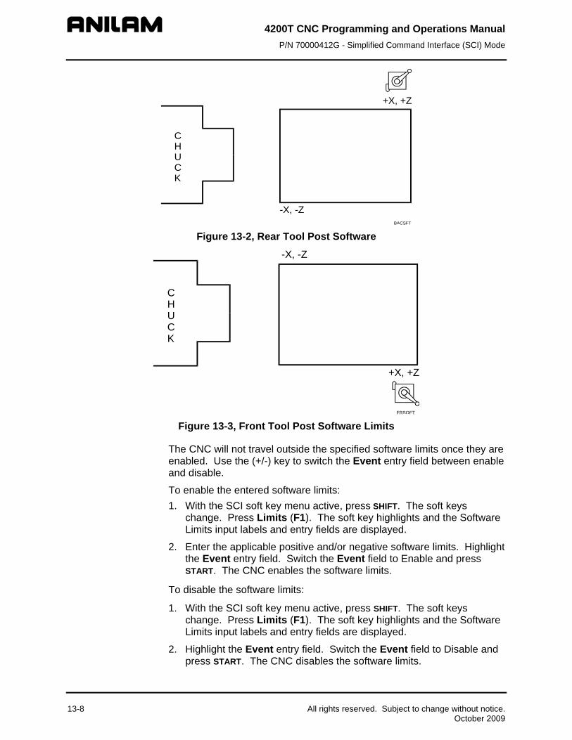
4200T CNC ProgrammiP/N 70000412G - Simplified Comman
ng and Operations Manual d Interface (SCI) Mode
+X, +Z
CHUCK
-X, -Z BACSFT
Figure 13-2, Rear Tool Post Software
+X, +Z
-X, -Z
CHUCK
FRSOFT
Figure 13-3, Front Tool Post Software Limits
The CNC will not travel outside the specified software limits once they are enabled. Use the (+/-) key to switch the Event entry field between enable and disable.
To enable the entered software limits: 1. With the SCI soft key menu active, press SHIFT. The soft keys
change. Press Limits (F1). The soft key highlights and the Software Limits input labels and entry fields are displayed.
2. Enter the applicable positive and/or negative software limits. Highlight the Event entry field. Switch the Event field to Enable and press START. The CNC enables the software limits.
To disable the software limits:
1. With the SCI soft key menu active, press SHIFT. The soft keys change. Press Limits (F1). The soft key highlights and the Software Limits input labels and entry fields are displayed.
2. Highlight the Event entry field. Switch the Event field to Disable and press START. The CNC disables the software limits.
13-8 All rights reserved. Subject to change without notice. October 2009

4200T CNC Programming and Operations Manual P/N 70000412G - Simplified Command Interface (SCI) Mode
All rights reserved. Subject to change without notice. 13-9 October 2009
Homing the Machine (G28)
To home all axes, press SHIFT. The soft keys change. Press Home (F6).
NOTE: The CNC will only perform a homing sequence on axes that have a homing parameter specified in the Setup Utility.
Making a Rough Turning Cut (G76)
NOTE: This cycle is similar in format and execution to a G76 Rough Turning Cycle. Only use this feature for rectangular cuts (90 degree corners).
Refer to Table 13-7. Make a rough cut by specifying the following parameters:
Table 13-7, Rough Cut Input Labels
Input Label
Entry Field Input Format
Description
Length xxx.xxxx The length of the roughing pass in Z.
Depth xxx.xxxx The depth in X to which the stock will be cleared.
Step xxx.xxxx The depth in X which will be removed in a single pass.
Feed xxx.x or xx.xxx IPM (G94) or IPR (G95), current active feedrate type.
All parameters are sign dependent, incremental values. In Diameter Mode, the CNC automatically adds 0.2 inch/4 MM (0.1inch/2MM, radius) in X to the first pass depth. (You must position the tool in X before beginning the first pass.) Subsequent passes are made at the depth entered by the operator.
Feedrate is optional. If no feedrate is entered, the CNC executes the cycle at the current feedrate.
To make a rough turning cut:
1. Position the tool at the starting point of the roughing cycle. Make sure the tool is 0.1 inch/2 MM from the work in X.
2. With the SCI soft key menu active, press Turn (F8). The soft key highlights and the Turning cycle input labels and entry fields are displayed.
3. Enter the parameters listed above and press START. The CNC executes the rough turning cut.
4. The CNC returns to the starting point after completing the cycle.

4200T CNC Programming and Operations Manual P/N 70000412G - Simplified Command Interface (SCI) Mode
13-10 All rights reserved. Subject to change without notice. October 2009
Making a Rough Facing Cut (G77)
NOTE: This cycle is similar in format and execution to a G77 Rough Facing Cycle. Perform only rectangular cycles (90 degree corners).
Refer to Table 13-8. Perform a rough facing cut on a piece of stock by specifying the following parameters:
Table 13-8, Rough Facing Cut Input Labels
Input Label
Entry Field Input Format
Description
Length xxx.xxxx The length of the roughing pass in X.
Depth xxx.xxxx The final depth in Z to which the stock will be cleared.
Step xxx.xxxx The depth in Z which will be removed in a single pass.
Feed xxx.x or xx.xxx IPM (G94) or IPR (G95), current active feedrate type.
All parameters are sign dependent, incremental values. The CNC automatically adds 0.1 inch/2 MM (diameter values) in Z to the first pass depth. (You must position the tool in Z before beginning the first pass.) Subsequent passes are made at the specified depth (step).
Feedrate is optional. If no feedrate is entered, the CNC executes the cycle at the current feedrate.
To make a rough facing cut:
1. Position the tool at the starting point of the facing cycle. Make sure the tool is 0.1 inch/2 MM from the work in Z.
2. With the SCI soft key menu active, press Face (F9). The soft key highlights and the Facing cycle input labels and entry fields are displayed.
3. Fill in the entry fields listed above and press START. The CNC executes the rough facing cycle. 2MM (0.1 inch) is added to the depth of the first pass.
4. The CNC returns to the starting point after completing the cycle.

4200T CNC Programming and Operations Manual P/N 70000412G - Simplified Command Interface (SCI) Mode
All rights reserved. Subject to change without notice. 13-11 October 2009
Cutting Threads (G83)
NOTE: This cycle is similar in function and execution to the G83 Threading Cycle.
Refer to Table 13-9. Perform a threading cycle to the target location by specifying the following entry fields:
Table 13-9, Threading Cycle to the Target Location
Input Label
Entry Field Input Format
Description
TPI** xxx.xxxx Threads per Inch. Specifies the number of threads per inch that will be cut.
Lead** xxx.xxxx Incremental Z distance between one thread and the next.
Length xxxx.x or xx.xxx
Incremental Z distance specifying the length of the threading pass.
FirstCut xxx.xxxx Incremental X distance, specifying the depth of the first threading pass.
**Specify TPI or Lead, but not both.
All entry fields are sign dependent, incremental values. In Diameter Mode, the CNC automatically adds 0.2 inch/4 MM (0.1inch/2MM, radius) in X to the depth of the first threading pass. (You must position the tool in X before beginning the first pass.) The number and depth of subsequent passes are determined by the CNC based on the pitch of the thread and the depth of the first cut.
To cut threads:
1. Position the tool at the starting point of the threading cycle. Make sure the tool is 0.1 inch/2 MM from the work in X.
2. With the SCI soft key menu active, press SHIFT. The soft keys change. Press Thread (F7). The soft key highlights and the Threading cycle input labels and entry fields are displayed.
3. Fill in the entry fields listed above and press START. The CNC executes the threading cycle.
4. The CNC returns to the starting point after completing the cycle.

4200T CNC Programming and Operations Manual P/N 70000412G - Simplified Command Interface (SCI) Mode
13-12 All rights reserved. Subject to change without notice. October 2009
Activating Absolute (G90) or Incremental (G91) Mode
Press Abs/Inc (SHIFT + F8) to switch the CNC between Absolute and Incremental Modes. The active mode (Absolute, G90 or Incremental, G91) will appear in the Machine Status Display Area of the screen. )
To switch the Abs/Inc Mode:
1. In SCI Mode, press SHIFT. The soft keys change.
2. Press Abs/Inc (F8). The CNC switches the Absolute/Incremental Mode setting.
To change the Absolute/Incremental Mode while another SCI command is active:
1. With another SCI command activated, press SHIFT. The soft keys change.
2. Press Abs/Inc (F8). The CNC switches the mode.
Setting the Feedrate to Feed per Minute (G94)
Refer to Table 13-10. Set the CNC to the Feed per Minute (G94) mode. The feedrate for Line and Arc moves will be at the specified Feed.
Table 13-10, Setting Feedrate to Feed per Minute
Input Label
Entry Field Input Format
Description
Feed xxxx.x Sets the CNC to the FPM (G94) rate specified in the entry field.
To set the feedrate to FPM (G94):
1. With the SCI soft key menu active, press SHIFT. The soft keys change. Press FPM (F2). The soft key highlights and the FPM input labels and entry fields are displayed.
2. Enter the desired feedrate (inch/MM) per minute. Press START. The CNC switches the active feedrate to FPM Mode. Line and Arc moves will be performed at the specified FPM.

4200T CNC Programming and Operations Manual P/N 70000412G - Simplified Command Interface (SCI) Mode
All rights reserved. Subject to change without notice. 13-13 October 2009
Setting the Feedrate to Feed per Revolution (G95)
Refer to Table 13-11. Set the CNC to Feed Per Revolution (G95) Mode. The feedrate for Line and Arc moves depends upon the programmed spindle RPM. For each revolution of the spindle, the CNC advances linearly by the Feed amount.
Table 13-11, Setting Feedrate to Feed per Revolution
Input Label
Entry Field Input Format
Description
Feed xxxx.x Sets the CNC to the FPR (G95) rate specified in the entry field.
To set the feedrate to FPR (G95):
1. With the SCI soft key menu active, press SHIFT. The soft keys change. Press FPR (F3). The soft key highlights and the FPR input labels and entry fields are displayed.
2. Enter the desired feedrate (inch/MM) per revolution. Press START. The CNC switches the active feedrate to FPR Mode. For every revolution of the spindle, the CNC advances the axes of motion by the specified FPR.
Setting Spindle Speed to Constant Surface Speed (G96)
Refer to Table 13-12. Set the CNC’s spindle speed to the Constant Surface Speed (CSS, G96) Mode. In this mode, the CNC adjusts the spindle RPM to maintain a constant surface speed. Spindle speed is inversely proportional to the distance from the part centerline.
Table 13-12, Setting Spindle Speed to Constant Surface Speed
Input Label
Entry Field Input Format
Description
GearCode M4X (41, 42, 43) Use an M-code to specify the gear range to be used. Gear code is optional.
Speed xxxx.x Sets the CNC to the surface feet (MM/Meter) per minute specified in the entry field. Speed must be given.
To set the CNC’s spindle speed to CSS Mode:
1. With the SCI soft key menu active, press CSS (SHIFT + F4). The soft key highlights and the CSS input labels and entry fields are displayed.
2. Enter the desired speed in feet (Meter/MM) per minute and the gear range to be used. Press START. The CNC switches the spindle to CSS Mode. The CNC constantly adjusts the spindle speed to maintain a constant surface speed, specified in the Speed entry field, for the axes of motion.
4200T CNC Programming and Operations Manual P/N 70000412G - Simplified Command Interface (SCI) Mode
13-14 All rights reserved. Subject to change without notice. October 2009
Setting the Spindle Speed to Revolutions per Minute (G97)
Refer to Table 13-13. Set spindle speed to the Revolutions Per Minute (RPM, G97) Mode. The spindle rotates at a constant RPM, specified in the entry field.
Table 13-13, Setting Spindle Speed to Revolutions per Minute
Input Label
Entry Field Input Format
Description
Gear Code M4X (41, 42, 43) Use an M-code to specify the gear range to be used. Optional.
Speed xxxx.x Sets the CNC to the FPR (G95) specified in the entry field. Required.
To set the CNC’s spindle speed to RPM Mode:
1. With the SCI soft key menu active, press SHIFT. The soft keys change. Press RPM (F5). The soft key highlights and the RPM input labels and entry fields are displayed.
2. Enter the desired spindle speed (inch/MM) per revolution and the gear range to be used. Press START. The CNC switches the spindle to the RPM mode. The CNC applies a constant RPM, specified in the Feed entry field, to the spindle.
Slave Mode
In Slave Mode, the CNC does not move the machine. The X-axis is slaved to the movement of the Z-axis handwheel. This means that both axes move when you rotate the Z-axis handwheel.
Press Slave (F10) to switch the Slave Mode OFF or ON. The soft key highlights when Slave Mode activates. When Slave Mode deactivates, the soft key is no longer highlighted.
For Taper (F5), Chamfer (F6), and Radius (F7) moves, the CNC enters the Slave Mode when the START key is pressed.
When the Slave Mode is deactivated, you can move the X and Z handwheels independently.

4200T CNC Programming and Operations Manual P/N 70000412G - Simplified Command Interface (SCI) Mode
Cutting a Taper
Refer to Table 13-14. Cut a Taper by specifying the following entry fields:
Table 13-14, Cutting a Taper
Input Label
Entry Field Input Format
Description
Type PosAngle/NegAngle Specifies whether the angle is measured in a positive or negative direction from the Z-axis. The 3 o’clock position along the Z-axis is zero degrees.
Angle xxx.xxx The angle of the taper, measured from the Z+ axis.
The PosAngle/NegAngle option is switched by pressing the (+/-) key. The given angle is always measured from the standard 3 o’clock reference. Refer to Figure 13-4.
10o
Positive Taper Angle170 deg. (from 3 o'clock)
SCITAPER
Figure 13-4, Defining a Taper Angle and Direction
To cut a taper:
1. Position the tool at the starting point of the first taper pass.
2. With the SCI soft key menu active, press Taper (F5). The soft key highlights and the Taper move input labels and entry fields are displayed.
3. Enter the parameters listed above and press START. Slave Mode activates.
4. Using the Z-axis handwheel, move the tool to perform the first taper pass. Stop turning the handwheel when the tool has cleared the stock.
All rights reserved. Subject to change without notice. 13-15 October 2009

4200T CNC Programming and Operations Manual P/N 70000412G - Simplified Command Interface (SCI) Mode
5. Press Slave (F10) to deactivate the Slave Mode and manually re-position the tool at the starting point of the next taper pass.
6. Press Slave (F10) to activate the Slave Mode and perform the next taper pass.
7. Repeat steps 5 and 6 until the taper is complete.
Cutting a Chamfer
Refer to Table 13-15. Cut a Chamfer move by specifying the following entry fields:
Table 13-15, Cutting a Chamfer
Input Label
Entry Field Input Format
Description
Type Positive/Negative Specifies whether the angle is measured in a positive or negative direction from the Z-axis. The 3 o’clock position along the Z-axis is zero degrees.
A Chamfer is actually a 45-degree taper, measured from the Z-axis.
Use the (+/-) key to switch the Type between Pos (positive) and Neg (negative). To cut a chamfer, follow the instructions for cutting a taper pass. Refer to Table 13-16 to define chamfer types.
Table 13-16, Positive and Negative Chamfers
Positive Chamfers Negative Chamfers I.D. Left I.D. Right O.D. Right O.D. Left
Refer to Figure 13-5. The diagram shows the different chamfer types possible.
Pos.
Pos. Neg.
Neg.SCICHAMF
Figure 13-5, Positive and Negative Chamfers
13-16 All rights reserved. Subject to change without notice. October 2009

4200T CNC Programming and Operations Manual P/N 70000412G - Simplified Command Interface (SCI) Mode
All rights reserved. Subject to change without notice. 13-17 October 2009
Cutting a Radius
Refer to Table 13-17. Cut a radius by specifying the following entry fields:
Table 13-17, Cutting a Radius
Input Label
Entry Field Input Format
Description
X Cent xxx.xxxx The X-axis center of the arc.
Z Cent xxx.xxxx The Z-axis center of the arc.
Cw/Ccw Cw/Ccw Defines the direction of an optional sweep angle (in conjunction with a beginning angle).
SweepAng xxx.xxxx Together with the beginning angle, defines an area beyond which the tool cannot travel during the Radius move.
The starting angle is determined by the position of the tool at the beginning of the Radius move and the location of the arc centerpoint (X Cent, Z Cent or XZ Cent).
To cut an arc:
1. Position the tool at the starting point of the arc move.
2. With the SCI soft key menu active, press Radius (F7). The soft key highlights and the Radius move input labels and entry fields are displayed.
3. Enter the parameters listed above and press START. Slave Mode activates.
4. Using the Z-axis handwheel, move the tool to perform the first radius pass. Stop turning the handwheel when the tool has cleared the stock.
5. Press Slave (F10) to deactivate the Slave Mode and manually re-position the tool at the starting point of the next pass, if more than one pass is required to complete the arc to the proper dimensions.
6. Press Slave (F10) to activate the Slave Mode and perform the next pass.
7. Repeat steps 5 and 6 until the arc is complete.


4200T CNC Programming and Operations Manual P/N 70000412G - Shape Editor
Section 14 - Shape Editor The Shape Editor is a graphic CNC programming tool. The Shape Editor enables you to write part subprograms without using G-codes. This section describes the Shape Editor’s features and outlines its use.
Before using the Shape Editor, the user should be familiar with programming techniques, including G-codes. Refer to Figure 14-1.
Drawing Tools
Display Area
All rights reserved. Subject to change without notice. 14-1 October 2009
Softkeys
PointerCoordinates
Abs/Inc Mode
Inch/MM Mode
Program Name
Figure 14-1, Shape Editor Screen
The Shape Editor’s features are described below:
Pointer Coordinates
Indicate X, Z position of the pointer.
Abs/Inc Mode indicator
Indicates the Absolute or Incremental Mode of the Shape Editor.
NOTE: The resulting subprogram will execute moves using absolute dimensions.
Inch/MM Mode Indicator Indicates Inch or MM Mode active. Pointer Used to select specific points for editing.
Soft Keys

4200T CNC Programming and Operations Manual P/N 70000412G - Shape Editor
14-2 All rights reserved. Subject to change without notice. October 2009
Display Area Viewing area.
Drawing Tools Tools used to create and edit shapes.
Soft Keys Shape Editor has two sets of soft keys: a default set and the Shape (F2) set.
The default soft keys provide tools for changing the setup, adjusting the display and managing shapes.
The Shape soft keys provide tools for moving the pointer, deleting shape segments and deleting geometry elements. Shape soft keys are switched on and off by pressing the Shape (F2) soft key. The Shape (F2) soft key label is highlighted when these soft keys are active. It is best to leave the Shape (F2) soft keys active while editing a shape.
Program Name Name of program linked to the shapes.
Activating the Shape Editor
To activate the Shape Editor, go to the Program Directory and press Shapes (F4). The program that highlights when the Shape Editor activates will be linked to shapes created or edited during that session.
Shapes are called from the main part program just like a G-code is called from a subprogram. Shapes are not in, nor viewable from the main program. Shapes files have the same filename as the part program minus the “.G” extension.
To activate the Shape Editor: 1. From the Program Directory, move the highlight to select the program
that will use the new or edited shapes. Create the program if necessary.
2. Press Shapes (F4). The Shape Editor activates.
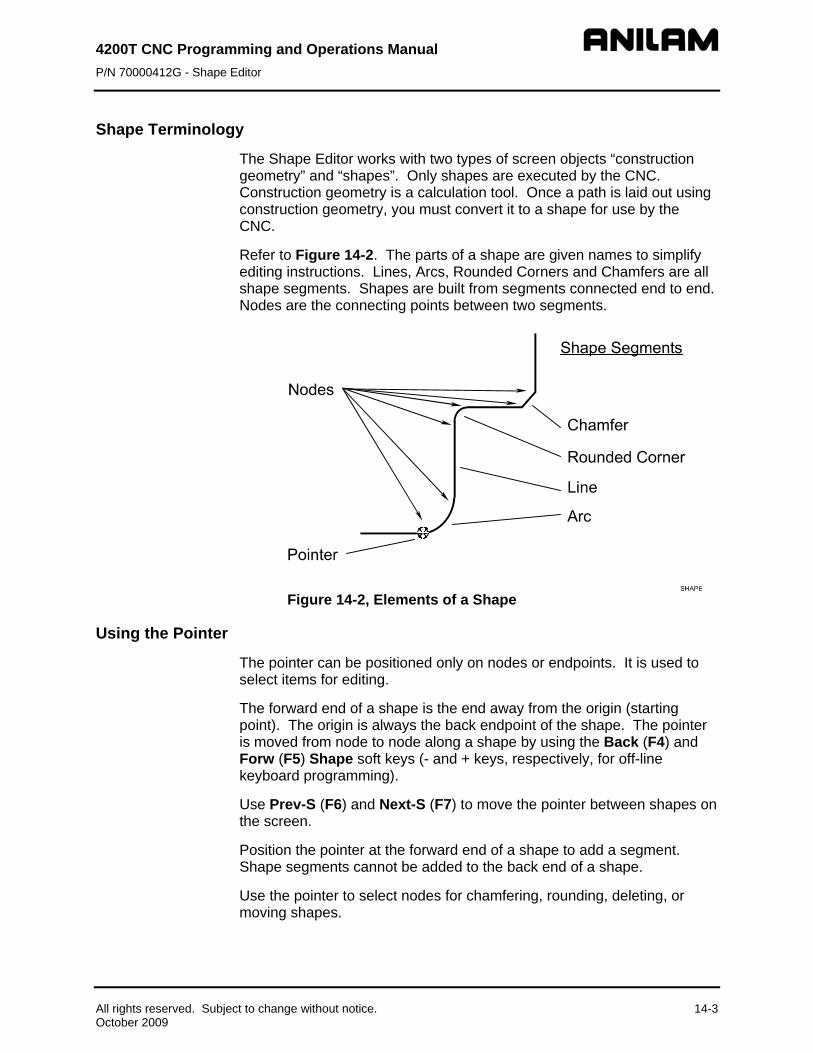
4200T CNC Programming and Operations Manual P/N 70000412G - Shape Editor
Shape Terminology
The Shape Editor works with two types of screen objects “construction geometry” and “shapes”. Only shapes are executed by the CNC. Construction geometry is a calculation tool. Once a path is laid out using construction geometry, you must convert it to a shape for use by the CNC.
Refer to Figure 14-2. The parts of a shape are given names to simplify editing instructions. Lines, Arcs, Rounded Corners and Chamfers are all shape segments. Shapes are built from segments connected end to end. Nodes are the connecting points between two segments.
Figure 14-2, Elements of a Shape
Using the Pointer
The pointer can be positioned only on nodes or endpoints. It is used to select items for editing.
The forward end of a shape is the end away from the origin (starting point). The origin is always the back endpoint of the shape. The pointer is moved from node to node along a shape by using the Back (F4) and Forw (F5) Shape soft keys (- and + keys, respectively, for off-line keyboard programming).
Use Prev-S (F6) and Next-S (F7) to move the pointer between shapes on the screen.
Position the pointer at the forward end of a shape to add a segment. Shape segments cannot be added to the back end of a shape.
Use the pointer to select nodes for chamfering, rounding, deleting, or moving shapes.
All rights reserved. Subject to change without notice. 14-3 October 2009

4200T CNC Programming and Operations Manual P/N 70000412G - Shape Editor
14-4 All rights reserved. Subject to change without notice. October 2009
Selecting Editing Tools
Refer to Figure 14-3, Shape Editing Tools. Editing tools create or edit shapes. Select an editing tool from the two columns of templates. Templates in the left column determine a new segment’s shape. Templates in the right column determine how the new segment will be defined.
Templates use a standard convention to describe moves. Each template depicts a segment with a hollow ball at one end and a solid ball at the other. The solid ball represents the pointer. The hollow ball is the endpoint of the segment being added. The Shape Editor will prompt you for the letter values shown in the template. Refer to Table 14-1.
Table 14-1, Template Lettering Convention
Value Required X - X-axis endpoint coordinate (usually a diameter).
Z - Z-axis endpoint coordinate.
I - X-axis coordinate of a circle or radius center.
K - Z-axis coordinate of a radius or circle center.
R - radius value.
A - an included or absolute angle.
C - circle.
D - distance.

4200T CNC Programmi P/N 70000412G - Shape Edit
ng and Operations Manual or
.
Figure 14-3, Shape Editing Tools
Select the shape of a new segment by moving the highlight up or down the left column of templates. Once the desired shape is highlighted, use the ENTER key or ARROWS to activate a description method in the right column. Only the Line and the Arc have more than one description method. (The geometry tool is covered later.)
Use the Line and Arc tools to rough out the main features of the shape. Once the major features have been drawn, add chamfers and corner rounding, as needed.
All rights reserved. Subject to change without notice. 14-5 October 2009

4200T CNC Programming and Operations Manual P/N 70000412G - Shape Editor
Line Tools
Refer to Table 14-2. In addition to the six line definition templates in the right column, the endpoint of a line can be described using endpoint definition tools. Refer to Table 14-3, Line Segment Endpoint Definition Tools. To select this option, highlight the Line template, and press ENTER. This activates the point definition templates displayed in the right template column.
Table 14-2, Line Segment Tools
Line Segment Template
Line Definition Templates
Values Required
14-6 All rights reserved. Subject to change without notice. October 2009
L
Right arrow permits use of these line definition templates.
Z
Line from pointer to endpoint parallel to Z-axis. Defined by Z position.
Use absolute or incremental Z-axis endpoint.
X
Line from pointer to endpoint parallel to X-axis. Defined by X position.
Use absolute or incremental X-axis endpoint.
XZ
Line from pointer to endpoint in any direction. Defined by X Z endpoint.
Use absolute or incremental X and Z-axis coordinates to define endpoint.
Line from pointer to endpoint in any direction. Defined by Radius and angle (polar coordinates).
Use radius and absolute angle.
Z Line from pointer to endpoint in any direction. Defined by Z endpoint coordinate and absolute angle.
Use absolute Z position and angle.
X
Line from pointer to endpoint in any direction. Defined by X endpoint coordinate and absolute angle.
Use absolute X position and angle.
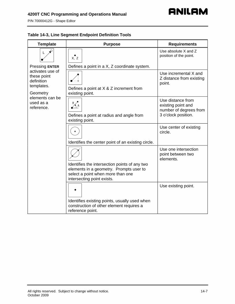
4200T CNC Programming and Operations Manual P/N 70000412G - Shape Editor
Table 14-3, Line Segment Endpoint Definition Tools
Template Purpose Requirements
L
Pressing ENTER activates use of these point definition templates.
Geometry elements can be used as a reference.
Defines a point in a X, Z coordinate system.
Use absolute X and Z position of the point.
Defines a point at X & Z increment from existing point.
Use incremental X and Z distance from existing point.
Defines a point at radius and angle from existing point.
Use distance from existing point and number of degrees from 3 o’clock position.
Identifies the center point of an existing circle.
Use center of existing circle.
Identifies the intersection points of any two elements in a geometry. Prompts user to select a point when more than one intersecting point exists.
Use one intersection point between two elements.
Identifies existing points, usually used when construction of other element requires a reference point.
Use existing point.
All rights reserved. Subject to change without notice. 14-7 October 2009

4200T CNC Programming and Operations Manual P/N 70000412G - Shape Editor
Arc Tools
Refer to Table 14-4. There are two types of Arcs, clockwise (Cw) and counterclockwise (Ccw). To change arc direction, highlight a template, and press ENTER. The definition templates are accessed with the right ARROW key, and selected using the up/down ARROW keys.
Table 14-4, Arc Segment Tools
Arc Template Arc Definition Template Values Required
& Press ENTER to switch between clockwise (Cw) & counter-clockwise Ccw).
X
14-8 All rights reserved. Subject to change without notice. October 2009
, Z
I, K
Arc from pointer to endpoint. Endpoint and center typed by operator.
Use absolute or incremental X, Z to define endpoint. Use absolute or incremental I, K to define center.
X, Z
R Arc from pointer to endpoint. Endpoint and radius typed by operator. Center calculated by CNC.
Use radius and absolute or incremental X, Z endpoint.
I, K
A
Arc from pointer to endpoint. Center and included angle typed by operator. Endpoint calculated by CNC.
Use absolute or incremental I, K centerpoint. Use incremental angle.
X , ZR
Tangent Arc from pointer to endpoint. Endpoint and radius typed by operator. Center is calculated by CNC. Center and radius values must be correct for tangent arc.
Use incremental radius and absolute or incremental X, Z endpoint.
X,Z
AR
Line from pointer followed by tangent arc. Line direction defined by the angle. Arc defined by X, Z endpoint and radius. Arc starts where tangent to line from pointer.
Use radius and absolute or incremental X, Z endpoint. Use absolute angle.
(Continued…)

4200T CNC Programming and Operations Manual P/N 70000412G - Shape Editor
Table 14-4, Arc Segment Tools (Continued)
Arc Template Arc Definition Template Values Required A
All rights reserved. Subject to change without notice. 14-9 October 2009
X,ZR
Arc followed by tangent line from pointer to endpoint. Line is defined from pointer to X, Z endpoint. Arc from pointer to tangent intersection with line is defined by radius.
Use radius and absolute or incremental X, Z endpoint. Use absolute angle.
Arc Tools
Use the Rounding tool to insert a radius segment in place of the sharp corner at the node between two line segments.
To round a corner:
1. Move the pointer to the corner being rounded.
2. Highlight the ROUNDING
Rnd
template, and press ENTER. The CNC will prompt for the blend radius.
3. Type the blend radius, and press ENTER. A new radius segment will be inserted in place of the original corner.
NOTE: Rounding can be performed only on a node located between two shape segments. The forward end or back end of a shape cannot be rounded.
Chamfering Corners
Use the Chamfering tool to chamfer selected corners on the shape.
To Chamfer a corner:
1. Move the pointer to the node to be chamfered.
2. Highlight the CHAMFERING
C h
template, and press ENTER. The CNC will prompt for the chamfer distance.
3. Type the desired chamfer distance, and press ENTER. A new line segment chamfering the corner will be added to the shape in place of the original corner.
NOTE: Use chamfering only on a node located between two shape segments. The start or end of a shape cannot be chamfered.

4200T CNC Programming and Operations Manual P/N 70000412G - Shape Editor
Example #1, Creating a Basic Shape
Refer to Figure 14-4. This example demonstrates the construction of a simple shape. Naturally, the shape to cut the part will extend beyond the actual dimensions at the ramp on and ramp off moves.
Figure 14-4, Example #1 Shape
All new shapes must start from a point (the shape origin) defined somewhere in the XZ coordinate system. In this example, X1, Z.1 is the starting point. The starting point must be defined using one of the point definition tools. This shape will be the only shape in the program.
NOTE: Point definition templates for shape segments look and act exactly like point definition templates for geometry elements. The difference is in how the point definition template is activated. Point definition templates activated from shape editing tools are always used to designate shape starting point or segment endpoints.
14-10 All rights reserved. Subject to change without notice. October 2009

4200T CNC Programming and Operations Manual P/N 70000412G - Shape Editor
Refer to Table 14-5. The only way to start a new shape is with the Create selection found in the S-EDIT Pop-Up Menu. This example starts in the Shape Editor with the default soft keys on and the Inch/Abs modes active and the CNC in the diameter mode. The XZ point definition tool defines the origin.
Table 14-5, Example #1 Keystrokes
Step 1: Activate SHAPE soft keys and create shape. Action Description
1. From the Program Directory, with the appropriate program name highlighted, press Shapes (F4).
1. Shape Editor activates.
2. Press Shape (F2). 2. The Shape soft keys activate. 3. Press S-Edit (F3). 3. A pop-up activates with Create
highlighted. 4. Press ENTER. 4. Creates new shape.
5. The and templates are highlighted. Press ENTER.
5. Activates template and prompts, “Enter X value:”
6. Type 1. Press ENTER. 6. CNC accepts value and prompts, “Enter Z value:”
7. Type .1. Press ENTER. 7. CNC accepts value.
8. The template is highlighted. Use
ARROWS to select
Z
. Press ENTER.
8. CNC activates template and prompts, “Enter Z value:”
9. Type -.5. Press ENTER. 9. Creates a line from the pointer to the entered endpoint in Z.
10. The template is highlighted. Use
ARROWS to select Z . Press ENTER.
10. Activates template and prompts, “Enter Z value:”
11. Type -1.25. Press ENTER. 11. CNC accepts Z value and prompts, “Enter angle:”
12. Type 150. Press ENTER. 12. CNC accepts angle value and creates a line from the pointer to the endpoint. The endpoint is defined by the entered Z coordinate and absolute angle.
All rights reserved. Subject to change without notice. 14-11 October 2009

4200T CNC Programming and Operations Manual P/N 70000412G - Shape Editor
Action Description
13. The template is highlighted. Use
ARROWS to select X
template.
13. Activates selected template and prompts, “Enter X value:”
14. Type 5. Press ENTER. 14. CNC accepts value.
15. Use ARROWS to select template. Press ENTER.
15. Activates selected template and prompts, “Enter Z value:”
16. Type -1.75. Press ENTER. 16. CNC accepts Z value.
17. Use ARROWS to select template. Press ENTER.
17. Activates selected template and prompts, “Enter X value:”
18. Type 5.2. Press ENTER. 18. CNC accepts X value.
Refer to Table 14-6.
Table 14-6, Example #1 Fit Shape to Window Step 2: Fit shape to window for visual inspection.
Action Description 1. Press Shape (F2). 1. The Shape soft keys activate. 2. Press Display (F5). 2. A pop-up activates with Fit highlighted. 3. Press ENTER. 3. CNC fits shape to window.
Refer to Table 14-7.
Table 14-7, Example #1 Round Radius Step 3: Insert blend radius.
Action Description 1. Press Shape (F2). 1. The shape soft keys activate. 2. Press Back (F4) three times. 2. The pointer moves to the intersection to
be rounded.
3. Use ARROWS to select
Rnd
template. Press ENTER.
3. CNC activates corner rounding and prompts, Enter blend radius:
4. Type .25. Press ENTER. 4. CNC rounds intersection at specified radius.
14-12 All rights reserved. Subject to change without notice. October 2009

4200T CNC Programming and Operations Manual P/N 70000412G - Shape Editor
All rights reserved. Subject to change without notice. 14-13 October 2009
Because there is only one shape in the example, it is Shape #1. Refer to Table 14-8 that shows how to use this in a program. Refer to “Executing Shapes in a Program” later in this section of this manual.
Table 14-8, Example #1, G-code Program
Block Description N1. G70 G90 G0 X0 Z0 T0 Rapids home, cancels all offsets and activates
Inch/Abs Modes. N2. T1 Activate T1 offsets. N3. X1 Z.1 G95 F.01 S800 M3 Rapid to start position. Set spindle speed and
activate spindle forward. N4. G73 W1 A.1 R.02 S.01 C1 B1 J.02 K.008
Activate clearing cycle with subprogram call to Shape #1 (W1).
N5. G0 X0 Z0 T0 M5 Cancel T1. Deactivate spindle. Rapid Home. N6. M2 End program.
Reversing an Arc’s Direction
Occasionally you might program an Arc move in the wrong direction. Instead of deleting the segment and redrawing it, reverse the Arc’s direction. Arcs at the end of a shape or between any two segments can be reversed.
To reverse an Arc’s direction:
1. Move the pointer to the Arc’s forward node and press S-Edit (F3). S-Edit Pop-Up Menu will activate.
2. Highlight Rev Arc, and press ENTER. The arc will be drawn in the opposite direction.
Deleting a Shape
When necessary, an entire shape can be deleted.
To delete an entire shape:
1. Use Prev-S (F6) and Next-S (F7) to move the pointer to occupy any node within the shape to be deleted.
2. Press S-Edit (F3). The S-Edit Pop-Up Menu activates.
3. Highlight Delete, and press ENTER. The CNC will prompt you to confirm the deletion.
4. Press Yes (F1) or No (F2) as required. Yes causes the shape to be deleted. No cancels the process.
Sometimes small bits of a shape will remain on the screen after deletion. Press the “R” REDRAW hot key to refresh the screen.

4200T CNC Programming and Operations Manual P/N 70000412G - Shape Editor
14-14 All rights reserved. Subject to change without notice. October 2009
Projecting Line Segments (Restoring Sharp Corners)
Use the Project feature to remove a blend radii and restore the sharp corners. This operation is called projecting because projections are added to line segments on both sides of a removed radius.
To remove a radius and restore a sharp corner:
1. Move the pointer to the forward node of the radius being removed.
2. Press S-Edit (F3). The S-Edit Pop-Up Menu will activate.
3. Highlight Project, and press ENTER. The CNC removes the radius and adds line projections forming a sharp angle. The editor will prompt you to join the lines.
4. To join the projections press Yes (F1). The collinear line segments are joined into a single, straight-line segment.
NOTE: Collinear lines are end to end lines that lie in the same direction.
Joining Line Segments
Sometimes what activates to be a single line segment is more than one line segment drawn end to end. The presence of the extra nodes within the segment can be detected by moving the pointer along the segment.
Collinear segments do not affect the execution of the move. Usually it is desirable to join collinear lines to keep the subprogram, and future editing sessions, as simple as possible.
To join collinear lines:
1. Position the pointer at the node between the collinear lines.
2. Press S-Edit (F3). The S-Edit Pop-Up Menu activates.
3. Highlight Join, and press ENTER. The unnecessary node is removed from the line.
Importing Shapes from Other Programs
Sometimes the same shape is used in more than one program. Rather than programming the shape more than once, you can import the shape from its original program.
To import an existing shape from another program:
1. Press S-Edit (F3). The S-Edit Pop-Up Menu activates.
2. Highlight Import, and press ENTER. The Shape Editor prompts operator for the name of the program containing the shape to be imported.
3. Type the program name, and press ENTER. The Shape Editor displays a list of the shapes contained in the source program.

4200T CNC Programming and Operations Manual P/N 70000412G - Shape Editor
All rights reserved. Subject to change without notice. 14-15 October 2009
4. Highlight the desired shape, and press ENTER. The editor will prompt you to find out if the origin of the shape should be changed.
5. Press Yes (F1) and type a new origin as prompted or press No (F2) to import the shape at its original position.
Deleting a Segment
You can delete segments from an end or the middle of a shape. When a segment is deleted, the node marked by the pointer and the preceding segment are removed. When a segment is deleted from the middle of the shape, the segment in front of the pointer is connected to the preceding node.
To delete the segment at the forward end of the shape:
1. Move the pointer to the forward end of the shape.
2. Press DelMove (F8), and press ENTER. The last shape on the segment is removed.
Sometimes small bits of a deleted shape will remain on the screen. Press “R”, REDRAW hotkey, to refresh the screen.
Changing the Shape Editor View
Display (F5) accesses all display functions. These functions perform the same operations as described in the Draw Mode, which enables you to test-run a program before cutting any material. Refer to “Section 8 - Draw Mode.”
Viewing a List of Shape Segment Details
To view the details of the moves in any shape:
1. Press Misc (F6). The Misc Pop-Up Menu activates.
2. Shapes List is highlighted by default. Press ENTER. The list of the shapes available in the file activates.
3. Highlight the shape to be viewed, and press ENTER. The details of the moves in the shape activate in a box on the screen.
The following details are presented:
Starting point (origin)
Line endpoint and lengths
Arc directions, centers, and radius

4200T CNC Programming and Operations Manual P/N 70000412G - Shape Editor
Deactivating and Activating Shapes
Shapes can be deactivated to prevent screen clutter. When a shape is deactivated, it is not deleted from the program. It is simply not displayed. A deactivated shape can be activated at any time.
To deactivate/activate a shape:
1. From the default soft key line press Setup (F9). A pop-up menu activates.
2. Highlight Shapes, and press ENTER. The Shape listing activates.
3. Highlight the shape being deactivated/activated and switch its status by pressing ENTER. The shape status will switch Off or On accordingly.
4. Press Setup (F9) to close the pop-up menus. When all pop-ups have been closed, the CNC activates/deactivates the shape, as indicated.
Using Construction Geometry
Construction Geometry can be used to find path intersections not given on the blueprint. The use of construction geometry can also eliminate the need for many trigonometric functions.
The geometry of a shape can be constructed on the screen using the geometry tools. Once the tool path is solved, the intersecting segments of the geometry are chained together to form a shape.
Construction geometry is useful when working with blueprints that contain limited information. Many combinations of geometry can be entered to help the programmer find intersections.
Points, lines and circles are the basic elements of all construction geometry.
Accessing Geometry Tools
To access the Geometry tools:
1. Move the left column highlight to select the GEOMETRY template.
2. Press ENTER to cycle the right column through three sets of geometry templates. When the desired templates are displayed, use the right ARROW key to highlight a template in the right column.
3. Highlight the desired tool, and press ENTER.
Points, lines and circles can be defined more than one way. Each geometry tool defines a geometry element a different way. Tools that require a point position to start will prompt you to select and activate an additional point definition tool.
14-16 All rights reserved. Subject to change without notice. October 2009

4200T CNC Programming and Operations Manual P/N 70000412G - Shape Editor
Lines and circles are drawn on the display with dotted lines. Points are marked by X’s. All geometry elements are numbered.
Geometry tools generally produce one of the three different elements. Some tools require certain elements to already be part of the geometry. First-time operators are encouraged to experiment with all Shape Editor drawing tools. The following tables (Table 14-9, Table 14-10, Geometry Line Tools, and Table 14-11, Geometry Circle Tools) are provided as a reference to the features of each tool. Look over each of the tables before attempting the examples.
Point Tools
Some of the point tools define the position of a point in the coordinate system, others allow the user to select an existing point in the geometry.
When using tools that require a starting point, a through point, or a from/to point, the Shape Editor will display a, “Select point definition . . .,” message. You must then activate an additional point tool and define the required point.
Tools that identify center points or element intersections will prompt for necessary element numbers, highlight all possible points, and prompt the user to select one.
Table 14-9, Geometry Point Tools
Template Purpose Requirements
Defines a point in a geometry. Must know absolute X and Z position of the point.
Defines a point at X & Z increment from existing point.
One endpoint must already be an element of the geometry.
Must know incremental X and Z distance from existing point.
Defines a point at radius and angle from existing point.
One endpoint must already be an element of the geometry.
Must know distance from existing point.
Must know number of degrees from 3 o’clock position.
Identifies the center point of an existing circle.
The circle must already be an element of the geometry.
All rights reserved. Subject to change without notice. 14-17 October 2009
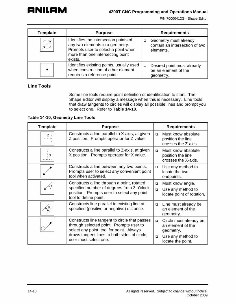
4200T CNC Programming and Operations Manual P/N 70000412G - Shape Editor
14-18 All rights reserved. Subject to change without notice. October 2009
e Purpose Requirements Templat
Identifies the intersection points of any two elements in a geometry. Prompts user to select a point when more than one intersecting point exists.
Geometry must already contain an intersection of two elements.
Identifies existing points, usually used when construction of other element requires a reference point.
Desired point must already be an element of the geometry.
Line Tools
Some line tools require point definition or identification to start. The Shape Editor will display a message when this is necessary. Line tools that draw tangents to circles will display all possible lines and prompt you to select one. Refer to Table 14-10.
Table 14-10, Geometry Line Tools
Template Purpose Requirements
Constructs a line parallel to X-axis, at given Z position. Prompts operator for Z value.
Must know absolute position the line crosses the Z-axis.
Constructs a line parallel to Z-axis, at given X position. Prompts operator for X value.
Must know absolute position the line crosses the X-axis.
Constructs a line between any two points. Prompts user to select any convenient point tool when activated.
Use any method to locate the two endpoints.
Constructs a line through a point, rotated specified number of degrees from 3 o’clock position. Prompts user to select any point tool to define point.
Must know angle. Use any method to
locate point of rotation.
Constructs line parallel to existing line at specified (positive or negative) distance.
Line must already be an element of the geometry.
Constructs line tangent to circle that passes through selected point. Prompts user to select any point tool for point. Always draws tangent lines to both sides of circle; user must select one.
Circle must already be an element of the geometry.
Use any method to locate the point.

4200T CNC Programming and Operations Manual P/N 70000412G - Shape Editor
Circle Tools
Some circle tools require point definition or identification when used, the Shape Editor will display a message when this is necessary. Circle tools that draw circles tangent to other circles, lines or points will construct all possible circles and prompt you to select one. Refer to Table 14-11.
Table 14-11, Geometry Circle Tools
Template Purpose Requirements
Constructs circle of specified radius tangent to any two points, lines or circles. Draws all possible solutions, user must select one.
Geometry must contain at least two elements.
Constructs circle of specified radius centered at any position. Prompts user to select any point tool to define circle center point.
Use any method to locate center point.
Must know radius.
Constructs circle of specified radius tangent to line and point. Prompts user to select any point tool to define point.
Line must already be an element of the geometry.
Constructs circle tangent to line with center at defined point. Prompts user to select any point tool to define center point.
Line must already be an element of the geometry.
Use any method to locate center point.
Constructs line tangent to any two circles. Always draws the four possible lines; user must select one.
Two circles must already be elements of the geometry.
Constructs line rotated specified number of degrees from 3 o’clock position and tangent to existing circle.
Circle must already be an element of the geometry.
Must know number of degrees of rotation from 3 o’clock position.
All rights reserved. Subject to change without notice. 14-19 October 2009

4200T CNC Programming and Operations Manual P/N 70000412G - Shape Editor
Example #2, Creating Construction Geometry and Chaining it Into a Shape
To better understand geometry tools, work through the following example. Note the templates used and the prompts requesting additional information. Refer to Figure 14-5 and Table 14-12, Exercise 2 - Steps 1 through 5.
Creating Construction Geometry
This example illustrates the use of construction geometry to calculate the path required to form a shape. When the geometry is complete, segments of the geometry are chained together to form a shape with the chaining tool.
Figure 14-5, Example #2, Construction Geometry Details
14-20 All rights reserved. Subject to change without notice. October 2009

4200T CNC Programming and Operations Manual P/N 70000412G - Shape Editor
All geometry tools are accessed with the left column GEOMETRY template highlighted. Highlight the template, and press ENTER to cycle through three sets of the geometry tool templates in the right column.
This six-step example starts in the Shape Editor with no other shapes or geometry present and the default soft keys showing.
Geometry should be constructed so each node of the required shape is an intersection of two geometry elements.
Table 14-12, Exercise 2 - Steps 1 through 5
Step 1: Create .75” and .5” radius circles. Fit geometry to inspect.
Action Description
1. Use ARROWS to highlight the geometry
tool template . Press ENTER until
the template activates in the right column.
1. When ENTER is pressed the CNC switches the available geometry tool menus.
2. Use ARROWS to highlight the template. Press ENTER.
2. Activates the template and prompts, “Enter R value:”
3. Type .75 (radius of first circle). Press ENTER.
3. Accepts Radius value and prompts, “Select center definition...”
4. The template is highlighted. Press ENTER.
4. Activates template and prompts, “Enter X value:”
5. Type .75 (X circle center). Press ENTER. 5. Accepts X value and prompts, “Enter Z value:”
6. Type -2 (Z circle center). Press ENTER. 6. Creates first circle.
7. The template is highlighted. Press ENTER.
7. Activates template and prompts, “Enter R value:”
8. Type .5 (second circle radius). Press ENTER.
8. Accepts radius and prompts, “Select center definition...”
All rights reserved. Subject to change without notice. 14-21 October 2009
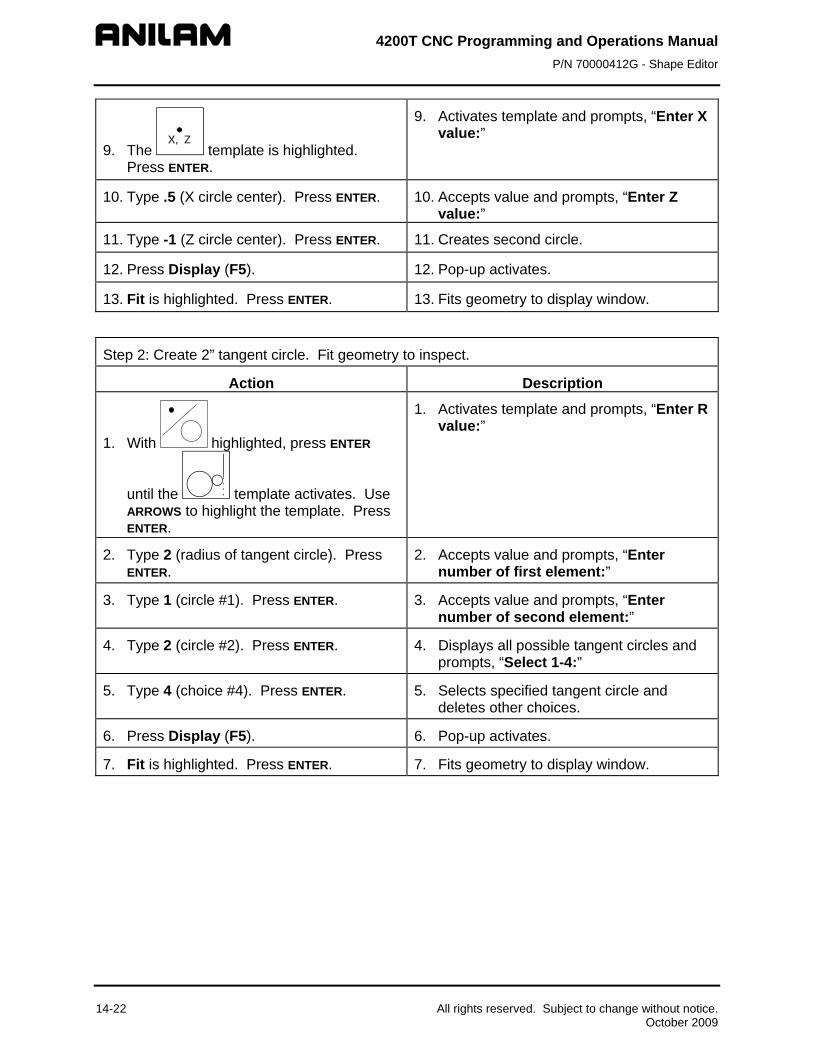
4200T CNC Programming and Operations Manual P/N 70000412G - Shape Editor
9. The template is highlighted. Press ENTER.
9. Activates template and prompts, “Enter X value:”
10. Type .5 (X circle center). Press ENTER. 10. Accepts value and prompts, “Enter Z value:”
11. Type -1 (Z circle center). Press ENTER. 11. Creates second circle.
12. Press Display (F5). 12. Pop-up activates.
13. Fit is highlighted. Press ENTER. 13. Fits geometry to display window.
Step 2: Create 2” tangent circle. Fit geometry to inspect.
Action Description
1. With highlighted, press ENTER
until the template activates. Use ARROWS to highlight the template. Press ENTER.
1. Activates template and prompts, “Enter R value:”
2. Type 2 (radius of tangent circle). Press ENTER.
2. Accepts value and prompts, “Enter number of first element:”
3. Type 1 (circle #1). Press ENTER. 3. Accepts value and prompts, “Enter number of second element:”
4. Type 2 (circle #2). Press ENTER. 4. Displays all possible tangent circles and prompts, “Select 1-4:”
5. Type 4 (choice #4). Press ENTER. 5. Selects specified tangent circle and deletes other choices.
6. Press Display (F5). 6. Pop-up activates.
7. Fit is highlighted. Press ENTER. 7. Fits geometry to display window.
14-22 All rights reserved. Subject to change without notice. October 2009

4200T CNC Programming and Operations Manual P/N 70000412G - Shape Editor
Step 3: Create tangent lines. Fit geometry to inspect.
Action Description
1. With highlighted, press ENTER
until the template activates. Use ARROWS to highlight the template. Press ENTER.
1. Activates template and prompts, “Enter angle:”
2. Type -20 (absolute angle from 3 o’clock). Press ENTER.
2. Accepts angle value and prompts, “Enter number of circle:”
3. Type 2 (circle #2). Press ENTER. 3. Displays all possible tangent lines and prompts “Select 1-2:”
4. Type 2 (line #2). Press ENTER. 4. Selects line 2 and deletes other choices.
5. With highlighted, press ENTER
until the template activates. Use ARROWS to highlight the template. Press ENTER.
5. Activates template and prompts, “Enter angle:”
6. Type 0 (absolute angle from 3 o’clock). Press ENTER.
6. Accepts angle value and prompts, “Enter number of circle:”
7. Type 1 (circle #1). Press ENTER. 7. Displays all possible tangent lines and prompts “Select 1-2:”
8. Type 2 (line #2). Press ENTER. 8. Selects line 2 and deletes other choices.
9. Press Display (F5). 9. Pop-up activates.
10. Fit is highlighted. Press ENTER. 10. Fits geometry to display window.
All rights reserved. Subject to change without notice. 14-23 October 2009

4200T CNC Programming and Operations Manual P/N 70000412G - Shape Editor
Step 4: Locate shape starting point.
Action Description
1. The template is highlighted.
Press ENTER until the template activates. Use ARROWS to highlight the template and press ENTER.
1. Activates template and prompts, “Enter Z value:”
2. Type .1 (Z position). Press ENTER. 2. Creates line parallel to X-axis at entered Z position.
3. With template highlighted,
press ENTER until the template activates. Use ARROWS to highlight the template and press ENTER.
3. Activates template and prompts, “Enter number of first element:”
4. Type 4 (line #4). Press ENTER. 4. Prompts, “Enter number of second element:”
5. Type 6 (line #6). Press ENTER. 5. Creates point (element #7) marked by an X.
14-24 All rights reserved. Subject to change without notice. October 2009

4200T CNC Programming and Operations Manual P/N 70000412G - Shape Editor
Step 5: Create ramp off geometry.
Action Description
1. Select the template. Press
ENTER until the template activates. Use ARROWS to highlight the template and press ENTER.
1. Activates template and prompts, “Enter Z value:”
2. Type -3 (Z position). Press ENTER. 2. Creates line parallel to X-axis at entered Z position.
3. With template highlighted,
press ENTER until the template activates. Use ARROWS to highlight the template, and press ENTER.
3. Activates template and prompts, “Enter X value:”
4. Type 2.5. Press ENTER. 4. Creates line parallel to Z-axis at entered X position.
All rights reserved. Subject to change without notice. 14-25 October 2009

4200T CNC Programming and Operations Manual P/N 70000412G - Shape Editor
Chaining Geometry Elements to Create a Shape
Refer to Table 14-13, Exercise 2, Step 6. A new shape must be created before chaining can occur, the shape starting point (origin) should be a point on an element of the construction geometry. The new shape will be chained, from the starting point, around various geometry elements.
When the CHAIN template is highlighted and ENTER is pressed, the Shape Editor prompts you to “Select element:”. Type a chain of intersecting geometry elements, each separated by a space and press ENTER. The editor will trace the new shape from intersection to intersection. Each intersection will become a node in the new shape.
The path around a circular geometry element can be either in a clockwise or counter clockwise direction.
If the intersecting geometry element is a circle, a positive element number creates a counterclockwise path, a negative element number creates a clockwise path.
NOTE: This refers to front tooling applications. All examples in the manual are front tooling. For rear tooling, enter a negative element number for counterclockwise and positive element number for clockwise path.
If the direction of the path around any element is incorrectly chained, the direction can always be reversed using the shape editing tools. Elements can be chained one at a time or all at once.
14-26 All rights reserved. Subject to change without notice. October 2009

4200T CNC Programming and Operations Manual P/N 70000412G - Shape Editor
Table 14-13, Exercise 2, Step 6
Step 6: Chain segments of geometry to form shape.
Action Description
1. Press S-EDIT (F3). 1. A pop-up activates.
2. Create is highlighted. Press ENTER. 2. Creates a new shape.
3. Use ARROWS to select the template. Press ENTER.
3. Activates template and prompts, “From point:”
4. Type 7 (point #7). Press ENTER. 4. The pointer activates at point 7.
5. Use ARROWS to select the template. Press ENTER.
5. Activates template and prompts, “Select element:”
6. Enter the elements to be chained into a single shape. Include direction for circles or arcs (- equals CW path; + or no sign equals CCW path):
4 space -2 space 3 space -1 space 5 space 8 space 9 ENTER.
6. Chains objects into a single shape.
7. Press Cancel (F9). 8. End exercise 2.
All rights reserved. Subject to change without notice. 14-27 October 2009
4200T CNC Programming and Operations Manual P/N 70000412G - Shape Editor
14-28 All rights reserved. Subject to change without notice. October 2009
Viewing a Listing of Geometry Elements
A complete listing of all the geometry elements and relevant position information is available.
To view the Geometry list:
1. From the default soft key line press MISC (F6). A pop-up menu activates.
2. Move the highlight to select Geometry List, and press ENTER. A listing of geometry elements and position data activates.
The following information is displayed:
Element number
Points - X and Z positions
Lines parallel to X-axis - Z-axis position
Lines parallel to Z-axis - X-axis position
Lines through a point - point position and angle
Circles - The center point and radius
Deleting Geometry Elements
After a shape has been chained together from Construction Geometry, the geometry can be deleted, if desired. Elements can be left in the program along with the shape.
To delete geometry elements:
1. Press DelGeom (F9). The Shape Editor prompts operator for the number of the geometry element to be deleted.
2. Type the element number, and press ENTER. The element is removed from the display.
Sometimes small bits of an element will remain on the screen after deletion. Press the “R” REDRAW hot key to refresh the screen.
NOTE: Deleted geometry cannot be undeleted.

4200T CNC Programming and Operations Manual P/N 70000412G - Shape Editor
All rights reserved. Subject to change without notice. 14-29 October 2009
Deleting All Geometry Elements
To delete all geometry elements:
1. With the Shape soft keys active, press SHIFT and DelAll (F9). The Shape Editor prompts operator to confirm deletion.
2. Press Yes (F1) to delete or No (F2) to cancel.
Sometimes small bits of a deleted element will remain on the screen after deletion. Press the “R” REDRAW hot key to refresh the screen.
NOTE: Deleted geometry cannot be undeleted.
Activate/Deactivating Geometry Elements
Geometry elements can be deactivated to eliminate clutter in the viewing area. Turning elements off is not the same as deleting them. Geometry elements that have been turned off can be turned back on at any time. Geometry elements are deactivated and reactivated by group.
To deactivate/activate geometry elements:
1. From the default soft key line press Setup (F9). A pop-up menu activates).
2. Move the highlight to select Geometry, and press ENTER. The second pop-up menu activates.
3. Move the highlight to select the category of elements to be activated/deactivated and switch the display status by pressing ENTER. Status is indicated by On/Off label adjacent to listing.
Geometry elements can be activated/deactivated in the following categories:
All All geometry elements Lines Lines only Circles Circles only Points Points Only
Shape Editor Hot Keys
Several keypad keys have additional functions to adjust the display. These functions are available when the Shape Editor is in use. These hot key functions are available in the Draw View Mode. See the section on Draw for more details on working with the display hotkeys. Refer to Table 14-14, Shape Editor Hot Keys.
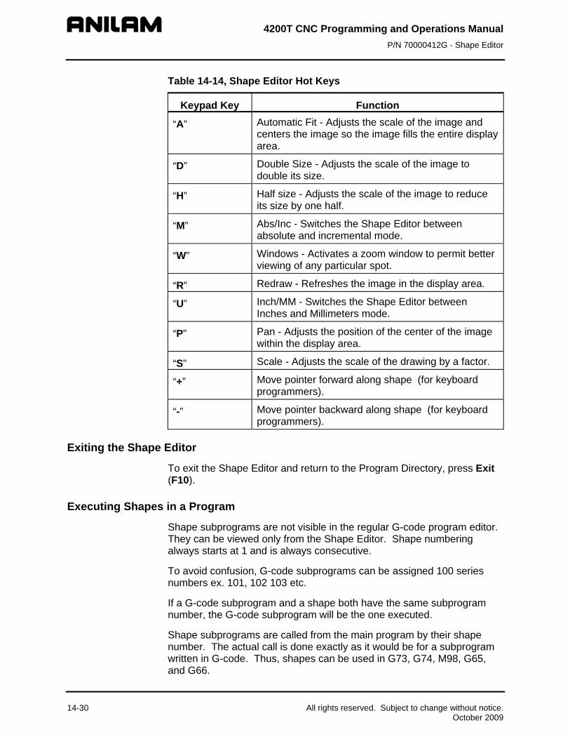
4200T CNC Programming and Operations Manual P/N 70000412G - Shape Editor
14-30 All rights reserved. Subject to change without notice. October 2009
Table 14-14, Shape Editor Hot Keys
Keypad Key Function
“A” Automatic Fit - Adjusts the scale of the image and centers the image so the image fills the entire display area.
“D” Double Size - Adjusts the scale of the image to double its size.
“H” Half size - Adjusts the scale of the image to reduce its size by one half.
“M” Abs/Inc - Switches the Shape Editor between absolute and incremental mode.
“W” Windows - Activates a zoom window to permit better viewing of any particular spot.
“R” Redraw - Refreshes the image in the display area.
“U” Inch/MM - Switches the Shape Editor between Inches and Millimeters mode.
“P” Pan - Adjusts the position of the center of the image within the display area.
“S” Scale - Adjusts the scale of the drawing by a factor.
“+” Move pointer forward along shape (for keyboard programmers).
“-” Move pointer backward along shape (for keyboard programmers).
Exiting the Shape Editor
To exit the Shape Editor and return to the Program Directory, press Exit (F10).
Executing Shapes in a Program
Shape subprograms are not visible in the regular G-code program editor. They can be viewed only from the Shape Editor. Shape numbering always starts at 1 and is always consecutive.
To avoid confusion, G-code subprograms can be assigned 100 series numbers ex. 101, 102 103 etc.
If a G-code subprogram and a shape both have the same subprogram number, the G-code subprogram will be the one executed.
Shape subprograms are called from the main program by their shape number. The actual call is done exactly as it would be for a subprogram written in G-code. Thus, shapes can be used in G73, G74, M98, G65, and G66.

4200T CNC Programming and Operations Manual P/N 70000412G - Shape Editor
All rights reserved. Subject to change without notice. 14-31 October 2009
Refer to Table 14-15.
Table 14-15, G-code for Example #2
Block Description N1. G70 G90 G0 X0 Z0 T0 Activate Inch/Abs Modes. Rapid
to Machine Home. Cancel offsets.
N2. T1 Activate T1 offsets. N3. X1 Z.1 G95 F.01 S800 M3 Rapid to start position at 800
RPM. Activate spindle forward. N4. M98 P1 Call Subprogram 1 (shape). N5. G0 X0 Z0 T0 M5 Rapid to Machine Home.
Deactivate tool and spindle. N6. M2 End program.
Managing Shape Files
Naming Shape Files
The CNC automatically names shape files created in the Shape Editor. The Shape files contain the same primary name as the G-code file with which they are associated. The Shape Editor generates several files with the G-code file but different extensions. Refer to Table 14-16 for a list of these file extensions.
Table 14-16, G-Code File Extensions
FILENAME.CAM CAM mode settings FILENAME.GEO Construction Geometry FILENAME.1 (or .2, .3) are Shapes FILENAME.$* Temporary files
Viewing Shape Files in the Program Directory
The types of files generated by the Shape Editor are discussed in the previous section. To view program names of all formats in the Program Directory:
1. From the Program Directory, press the SHIFT key. The soft key menu changes.
2. Press SHIFT + F9 (Display) until all shape files are viewed.

4200T CNC Programming and Operations Manual P/N 70000412G - Shape Editor
14-32 All rights reserved. Subject to change without notice. October 2009
Deleting Shape Files
CAUTION: Do not delete a shape file unless the associated shape is no longer needed to produce the part. If the main program calls a shape that has been deleted, the CNC generates an error message.
To delete .CAM and .GEO files:
1. From the Program Directory, highlight the filename and press Delete (F3). The shape file is deleted.
To delete the .1, .2, .3 files:
1. From the Shape Editor, press Shape (F2). The soft keys change.
2. Press S-EDIT (F3). Pop-up activates.
3. Highlight Delete. Prompt activates, “Sure you want to delete current shape?”
4. Press Yes (F1). Shape is deleted. Associated file will no longer activate in the Program Directory. Other shape files for the program are not affected.
To delete $ files:
1. .$ files will never remain in the user’s directory under normal circumstances. If found, they can be deleted from the Program Directory.
2. Highlight the program name and press Delete (F3). The file is deleted.
Backing Up Shapes
Make sure to back up all necessary shape files when backing up the main G-code program.
Shape Editor Settings
The Settings menu allows you to configure various Shape Editor characteristics.
To access the Settings menu:
1. From the default soft key menu press SETUP (F9). The pop-up menu activates.
2. Settings is highlighted. Press ENTER and the settings menu activates. Individual settings are made by highlighting a choice and toggling the setting with the ENTER key.
The various Shape Editor settings are as described in Table 14-17, Shape Editor Settings. Shape Editor settings are preserved from session to session.

4200T CNC Programming and Operations Manual P/N 70000412G - Shape Editor
All rights reserved. Subject to change without notice. 14-33 October 2009
Table 14-17, Shape Editor Settings
Action Description
Dimensions Switches dimensioning mode and angles between absolute and incremental.
Input Units Switches units mode between inches and Millimeters.
Arrows Switches arrows that activate on the 1st move of any shape, to be turned On/Off. These arrows tell the programmer the direction of the shape (default is on).
Labels Switches labels On/Off. The labels refer to the numbers of each shape, path or geometry element, such as 1, 2, 3, etc. (default is on).
Axes Switches axes lines On/Off (default is on).
Grid Allows selection of solid, dotted, or no grid lines.
Length Allows selection of grid spacing.
Verifying Shapes
Run the program containing the shapes in Draw Mode. If problems arise, edit the shapes in the Shape Editor and re-run the program in Draw to verify corrections.


4200T CNC Programming and Operations Manual P/N 70000412G - Communication
Section 15 - Communication
Introduction
The CNC is equipped to exchange data with other RS-232 compatible devices. The baud rate, parity, data bits, stop bits, and software parameters of the CNC and the device it is communicating with must agree for RS-232 communications to work.
Default communication parameters are entered in the device’s setup utility when the CNC is first setup. These parameters can also be changed from the Communications screen. Parameter changes made in the Communications screen are not permanent. Every time the control is powered up, the CNC’s default settings are reloaded.
CAUTION: Only qualified personnel should attempt to alter settings in the CNC’s setup utility. Incorrect settings may disable the device.
NOTE: The setup file is reloaded whenever setup changes are made and every time the CNC is powered on.
Installing the RS-232 Cable
RS-232 communication requires a cable connection between the sending and receiving devices. The machine builder determines the location of the DE-9 connector. Typically, a DE-9 connector is used on the machine. The other end of the cable must be connected to the other device.
Refer to Figure 15-1. It is important to use a cable designed for RS-232 communication. Cables designed for RS-232 communications have the wires between pins 2 and 3 internally crossed.
Figure 15-1, RS-232 Communication Connector
Data sent from pin 3 (transmit) of one device must go to pin 2 (receive) of the other. This is the only way RS-232 can work.
Computer cables designed as extension cords for computer peripherals cannot be used for RS-232 communications (pins 2 & 3 are not crossed).
All rights reserved. Subject to change without notice. 15-1 October 2009

4200T CNC Programming and Operations Manual P/N 70000412G - Communication
Accessing the Communication Utilities
To access the Communication screen:
1. With the CNC in the Manual Mode press Program (F2). The Program Directory activates.
2. Press Utility (F9). A pop-up displays.
3. Move highlight to select Communications, and press ENTER. The communication screen is displayed. Refer to Figure 15-2.
NOTE: The program marked by the highlight when the Communications screen is activated is the default selection for sending.
ProgramRS-232 SerialCommunication Parameters
Figure 15-2, RS-232 Communication Screen
PROGRAM The program selected for
transmission. SERIAL COMMUNICATIONS PARAMETERS
Settings required for the two devices to send and receive programs.
15-2 All rights reserved. Subject to change without notice. October 2009

4200T CNC Programming and Operations Manual P/N 70000412G - Communication
Setting Communication Parameters
This manual does not attempt to discuss the merits of the different parameter choices. Refer to an appropriate computer communications reference for this information.
NOTE: Both the sending and receiving devices must have the same baud, parity, data bits, stop bits, and software parameter settings.
Refer to Figure 15-3.
Figure 15-3, Parameter Settings Pop-Up
To change communication parameters:
1. From the Communications screen, press Param (F5). Parameter Settings pop-up is displayed.
2. Highlight the setting to be changed, and press ENTER.
3. When you select the Port, Baud, or Parity parameter, the CNC activates an additional pop-up. In the pop-up, select the appropriate setting, and press ENTER to store the setting.
4. For the Data Bits, Stop Bits, Software, or Data Type parameter, press ENTER to cycle through the available choices.
Communication Port
Most CNC installations have at least one RS-232 connector. It is usually labeled and mounted on the back of the console. The CNC sends signals via its COM1 port to the RS-232 connector. This configuration cannot be changed. Personal computers that run the offline software can use COM2 if they are equipped with the necessary hardware.
Baud
The CNC supports the following baud rates: 110, 150, 300, 600, 1200, 2400, 4800, 9600, or 19,200. [Default: 9600]
All rights reserved. Subject to change without notice. 15-3 October 2009

4200T CNC Programming and Operations Manual P/N 70000412G - Communication
15-4 All rights reserved. Subject to change without notice. October 2009
Parity
The CNC supports the following parity settings: Odd, Even, or None. [Default: Even]
Data Bits
The CNC supports the following data bit settings: 7-bit or 8-bit. [Default: 7-bit]
Stop Bits
The CNC supports the following stop bit settings: 0-bit or 1-bit. [Default: 1-bit]
Settings
The CNC supports the following protocol settings: ON or OFF. [Default: ON] Software protocol is frequently referred to as “Xon” or “Xoff”, or “handshaking” in commercial communications packages.
Data Type
The CNC supports the following data display types: ASCII or BINARY. [Default: ASCII] This setting does not affect the data exchanged, only how it appears on the screen during transmission.

4200T CNC Programming and Operations Manual P/N 70000412G - Communication
Testing the Data Link
The CNC has a utility to test the data link. With the CNC connected to another machine, set the parameters on both machines. If the other machine has a manual test screen, activate it.
Activating the Test Link Screen
Refer to Figure 15-4. With the Communications screen active, press TestLnk (F8). The Test Link screen displays.
LoadedProgram
ActiveMode
TransmitAreaActive
Settings
ReceiveArea
Figure 15-4, Test Link Screen Setting Test Link Display Modes
The operator tests the link by visually verifying that the test data sent matches the test data received. The data type setting determines how characters appear on the screen.
If the data type is set to ASCII, letters and numbers are displayed. If the data type is set to binary, the hexadecimal equivalent is displayed. Set both devices to use the same data display type.
NOTE: Hexadecimal characters appear as pairs of numbers or numbers and letters.
To change the Test Link screen data display:
1. Press PARAM (F9), and Down Arrow to #7- Data Type. Press ENTER to toggle. The current mode is displayed in the settings area of the Test Link screen.
All rights reserved. Subject to change without notice. 15-5 October 2009

4200T CNC Programming and Operations Manual P/N 70000412G - Communication
15-6 All rights reserved. Subject to change without notice. October 2009
Testing the Link
To test the link:
1. Set up an RS-232 connection with another device.
2. Set the other device to receive.
3. With the Link Test screen active use the CNC’s keypad to type in any series of numbers. These characters will appear in the transmit area.
4. Verify that the characters are correctly received at the other device.
5. Set the other device to transmit.
6. Manually transmit a series of characters from the other device.
7. Verify the characters sent to the CNC correctly appear in the receive area.
Clearing the Receive Area
Clear the receive area by pressing the ClearRx (F3) key.
Clearing the Transmit Area Clear the transmit area by pressing the ClearTx (F5) key.
Sending a Program
The name of the program marked by the highlight when the Communications screen was activated is listed next to the PROGRAM label on the screen. The CNC will send this program unless another program is selected. The CNC will prompt the operator to select another program during the sending process.
1. With the Communications screen active, the parameters set and the link tested, press Send (F3). The CNC prompts the operator to send the selected program or to change the program being sent.
2. Press Select (F1). The CNC sends the program. – or – Press Change (F3). The CNC prompts the operator to type in the
name of the desired program.
Receiving a Program
The operator must key in a name for the received program before receiving it from the other device.
To receive a program:
1. With the Communications screen active, the parameters set and the link tested, press Receive (F1). The CNC prompts operator to key in a name for the incoming program.
2. Key in the desired name, and press ENTER. The CNC displays a “READY TO RECEIVE . . .” message.
3. Start transmission from sending device.

4200T CNC Programming and Operations Manual P/N 70000412G - Communication
All rights reserved. Subject to change without notice. 15-7 October 2009
Setting the Transmission and Receiving Display
If the CNC is transmitting or receiving with the Text Mode active, the exchanged program will be displayed on the screen. If the Text Mode is off, the display area will remain blank.
The Text (F4) soft key label is highlighted when the Text Mode is active.
The “Transfer In Progress” symbol (just above the soft key line) cycles when data is exchanged.
Activate or deactivate text mode by pressing Text (F4) while transmitting or receiving.
NOTE: In general, transmission will occur faster with Text mode Off.
Holding Transmission/Receiving Operations
When sending or receiving programs the operation can be paused by pressing the Hold (F1) key. Press Resume (F2) to continue the exchange.
NOTE: If the CNC is receiving a program and either device’s software parameter (Xon/Xoff) is set to OFF, there is a possibility a hold will overload the CNC’s buffer causing portions of the program to be lost. Operating with the software parameter (Xon/Xoff) ON is recommended.

4200T CNC Programming and Operations Manual P/N 70000412G - Communication
15-8 All rights reserved. Subject to change without notice. October 2009
Using Data Control (DC) Codes
Data Control (DC) codes are sometimes required to automate the operation of a paper tape reader or punch. Refer to Table 15-1 for the available DC Codes.
Table 15-1, DC Codes
ASCII Function Hex Code CNC Key
DC1 Reader Start 0x11 Q
DC2 Punch Start 0x12 R
DC3 Reader Stop 0x13 S
DC4 Punch Stop 0x15 T
The “ASCII” column lists the codes required to perform the corresponding “Function.” The “Hex Code” is the hexadecimal equivalent of the ASCII code. The “CNC Key” column lists the key you press on the CNC keypad or a PC keyboard to transmit the required DC code.
A reader or punch will turn ON (start) or OFF (stop) in response to these codes. To test reader or punch communication, activate the Communications screen and press any of these keys. The paper tape reader or punch should respond appropriately.
Using DC Codes in Receive Mode
Usually, a receive operation involves the paper tape reader. You must start the reader, thereby initiating the reading of the paper tape. Do this after the CNC has been set up to receive the file.
1. Set up to the CNC to receive a program.
2. Press 1 to send the DC1 code to the reader. The reader starts.
3. After the CNC has read the tape, press 3 to stop the reader, if necessary. The CNC sends the DC3 code to the reader and the reader stops.
Using DC Codes in Send Mode
Usually, a send operation involves the paper tape punch. Set up and start the punch prior to initiating the send operation.
1. Select the program that will be sent to the tape punch.
2. Press 2 to send the DC2 code to the punch. The punch starts.
3. Press Send (F3) to start sending the program. If necessary, change the name of the program.
4. When the program has been completely transferred to the punched tape, press 4 to stop the punch, if necessary. The CNC sends the DC4 code to the punch and the punch stops.

4200T CNC Programming and Operations Manual P/N 70000412G - Advanced Programming Features
All rights reserved. Subject to change without notice. 16-1 October 2009
Section 16 - Advanced Programming Features
Block Separator Format G90 G01 G95 X0 Z0 F.003 ; X1 Z-1 ; Z-2 ; X0 ; Z0 Description CNC feeds to X0, Z0 in Abs/Inch mode with Feed Per
Revolution active. It feeds to four separate coordinates in subsequent moves.
Block separators (;) may be used to place several functions on a single line of program. Use a semi-colon (;) to designate a block separation. This can be particularly useful while inputting M.D.I moves in the Manual Mode. With block separators, several moves can be made from one input to the command line.
NOTE: The number of separated steps in a program file is only limited by the memory available.
Modifiers Format G02 X1.5 Z-1.5 I&A1.5 K&A-1.0 Description The A modifier is used to make the I and K center points
of an arc abs. (Arc centerpoints are incremental by default.)
Modifiers are addresses that will allow a CNC user to modify the way a word address is interpreted by the CNC. For example, one value in an Inch program may be changed to MM without programming G71. An arc center I or K may also be changed to be an Absolute value using address modifiers. Refer to Table 16-1 for a list of possible modifiers.
Table 16-1, Address Modifiers
Modifier Description A Force the address word to be ABSOLUTE. D Force the address word to be INCREMENTAL. E Force the address word to be INCH. M Force the address word to be MILLIMETER.
The address and modifier must be accompanied by the ampersand (&) character. The ampersand character must be placed between the address to be modified and the modifier. The address is programmed first, followed by the (&), followed by modifier, followed by the value.
The modifier is non-modal, and is only used for the address it accompanies.

4200T CNC Programming and Operations Manual P/N 70000412G - Advanced Programming Features
16-2 All rights reserved. Subject to change without notice. October 2009
Expressions and Functions
Expression commands can be used within a program to do complex mathematical calculations. Parentheses should enclose each and every expression. The order of hierarchy of commands follows the standard of mathematics. Refer to Table 16-2 for a list of operators and functions.
Table 16-2, Operators and Functions
Operator Function Format Description ( ) expression
function (parentheses)
G01 X(#100 + #101)
All calculations must be enclosed in parentheses. This defines an expression function.
* Multiplication G00 Z(#102 *#103) Moves Z to product of #102 and #103 / division Loop (5/2/0.1) Loops 25 times % modulo gives the
remainder of a function
G01 X(8 % 3) Feeds X2. The number 2 comes from the remainder of 3 into 8
+ , - addition, subtraction
G01 X(3+2) G01 X(3-2)
Addition and subtraction.
> relational, greater than
(#101 > #103) true if #101 is greater than #103
< relational, less than
(#101 < #103) true if #101 is less than #103
= relational, equal to (#100 = #101) True if #100 is equal to #101 != relational, not
equal (#100 != #101) True if #100 does not equal #101
round round up or down, automatically
#101=1.5; G01 X(round(#101))
Moves X2
#102=1.498; G01 X(round(#102))
Will round fractions greater than .500000 up and will round fractions less than .500000 down. Moves X1.
fix discard fraction less than 1
#101=(5/2); G01 X(fix(#101))
Moves X2. Fix will round (n) down to the next integer.
fup raise fraction up 1 #101=(5/2); G01 X(fup(#101))
Moves X3. Fup will round (n) up to the next integer.
var true if variable defined, false otherwise
Var(#100) True if #100 has been defined false if not. Var (n) is used to check if a user variable has been defined in a program.
sin sine trigonometric function
G01 X(cos(15)) Z(sin(15))
Moves along the hypotenuse of a 15 degree angle with a hypotenuse of 1. Sin (n) will give the sine of (n).
cos cosine trigonometric function
Cos (n) Cos (n) will give the cosine of (n).
(Continued…)

4200T CNC Programming and Operations Manual P/N 70000412G - Advanced Programming Features
All rights reserved. Subject to change without notice. 16-3 October 2009
Table 16-2, Operators and Functions (Continued)
Operator Function Format Description tan tangent
trigonometric function
Tan (n) Tan (n) will give the tangent of (n).
asin arc sine asin(n) Will give the inverse of sine or 1/sin acos arc cosine acos(n) Will give the inverse of cosine or 1/cos. atan arc tangent atan(n) Will give the inverse of tangent or 1/tan. abs absolute value abs(-n)= n. Will give the absolute value of (n). sqrt square root Sqrt(9) = 3 Gives the square root of (n). ln natural logarithm Ln (n) Gives the natural logarithm of (n) log logarithm base 10 Log (n) Gives the logarithm of (n). exp exponential EXP (n) Gives the exponent of (n). trun truncate TRUN (n) Truncates the value of (n). ! unary logical not (! = (#100)) Not equal to value in #100. + unary logical
positive (+(#101)) Means positive whatever value is in
#101. - unary logical
negative (-(#100)) Means negative whatever value is in
#100 # indirection ##102 One level of indirection
System Variables
System variables are variables that are set aside for the CNC system to use. Some of these variables may be useful for the user to know when programming macros. System variables range from #1000 to #1099. Refer to Table 16-3.
Most of these variables are read only and cannot be changed (written to). There are a few exceptions to this rule (block skip variables).
Table 16-3, System Variables
Variable Address Description #1000 to #1009 Block skip variables (Read/write allowed). #1010 and #1012 Commanded ABS tool position
#1010 = X #1012 = Z
#1016 Current G motion code: 0=rapid, 1=feed, 2=cw arc, 3=ccw arc, 5=elipse
#1019 Current X tool length offset. #1020 Current tool radius times 2. (diameter)
(Continued…)

4200T CNC Programming and Operations Manual P/N 70000412G - Advanced Programming Features
16-4 All rights reserved. Subject to change without notice. October 2009
Table 16-3, System Variables (Continued)
Variable Address Description + Current Z tool length offset. #1022 Current feedrate. #1023 Current rapid rate. #1024 Current RPM. #1030 Stock variable #1031 Acute angle for rounding compensated
intersections (default = 15.0 degrees). #1032 Number of look- ahead blocks for tool nose
compensation. #1040 Real time tool compensation (for ellipse,
0=off, 1=outside, 2 inside. #1041 Current program tool compensation (40=off,
41=left, 42=right. #1050 and #1052 Actual ABS position
#1050 = X #1052 = Z
#1070 Current XZ dimension (70=inch, 71=mm). #1090 Current XZ dimension (90=ABS, 91
=incremental)
User Variables
User variables are variables that are set aside for the programmer to use. They consist of local variables, common variables, read only variables, and block skip variables. These variables can be written to, or read from.
Local Variables
Local variables range from #1 to #99. These variables can only be used inside the body of a subprogram (or macro or parametric program). Errors will occur if they are used in the main body of the program. Their values will not hold from one subprogram to another. This prevents the operator from assigning conflicting values to the variables.
Common (Global) Variables
Common variables range from #100 to #220 and are read and write. These variables can be used anywhere in the program or subprogram and their value will remain.

4200T CNC Programming and Operations Manual P/N 70000412G - Advanced Programming Features
All rights reserved. Subject to change without notice. 16-5 October 2009
Read Only Variables
These variables range from #221 to #250 and are read only in macros. Read only variables must be assigned in the main program. Once set, the contents can be used in subprograms or macros as read only variables.
Block Skip Variables
Refer to Table 16-4. If the machine is provided with a block skip switch, all blocks containing the slash character will be skipped or not skipped, depending on the switch position. A variable does not need to be set for this to occur.
Selective block skips (/(n)) are not affected by the switch. They are always turned off or on by setting their variable (0 = off; 1 = on).
If no block skip switch is available, M9345 X1 must be programmed as the first block of any program that will use skip functions and variable #1000 = 1 must be programmed to skip regular slash blocks.
Table 16-4, Block Skip
Block Description M9345 X 1 Enables block skip N11 #1000 = 1 Sets block skip to On N12 G01 X1.125 G95 F.003 N13 X1.125 Z-.125 N14 Z-2.0 /N15 X1.1375 Z-2.125 This line is skipped by the
CNC N16 Z-4.0 N17 G00 X4.0
The slash (/) can appear anywhere in the block. It is recommended that the operator put the slash (/) before the block number.

4200T CNC Programming and Operations Manual P/N 70000412G - Advanced Programming Features
16-6 All rights reserved. Subject to change without notice. October 2009
Setting Selective Block Skips Format #100n, where n is a number 1 - 9 The programmer can use up to 9 optional block skips. Refer to Table 16-5.
Table 16-5, Selective Block Skip
Program Description M9345 X 1 Enables block skip N11 #1002 = 1 Sets block skip variable N12 G01 X1.125 G95 N13 X1.125 Z-.125 N14 Z-2.0 /2 N15 X1.1375 Z-2.125 This line is skipped by the CNC.
If #1002 = 0, block N15 will be executed.
N16 Z-4.0 N17 G00 X4.0
Parameters and Variable Registers
A macro is a series of instructions designed to achieve a specific result for a given set of constraints. For example, a simple component of any size will always have a stock diameter from which it was machined, a length of the turned diameter and a depth or difference of that diameter. It follows then, that many turned diameters of different sizes can be cut using a similar tool-path with longer or shorter moves for the tool-path. If the constraints of the diameter are processed by a suitable program, a tool-path can be calculated by the control to cut the particular diameter. Such a program may be called a macro or parametric program.
The constraints of the diameter, or the features required, are its parameters. Because particular parameters for any feature will vary as dimensions are changed, the parameters are often called variables.

4200T CNC Programming and Operations Manual P/N 70000412G - Advanced Programming Features
All rights reserved. Subject to change without notice. 16-7 October 2009
Contents of Variables
It is often useful to know the contents of a variable when programming to assist in testing. Using the PRINT command, the contents of a variable can be displayed on the screen in Manual, Single Step, Automatic and Graphic modes. The format is PRINT number, number. Refer to Table 16-6.
Table 16-6, Print Display
Format Description PRINT 200 Displays the contents of the variable (#200) N180 PRINT 110 Display contents of the variable(#110) as part
of program execution
If the numbers are separated by commas, several variables can be printed simultaneously, but too many will cause numbers to print off the screen. Print will not wrap output.
In Manual mode, type PRINT 110, then START to display the contents on the SCREEN.
Instead of typing the whole word PRINT, a short form is available. ]P is interpreted as print.
Setting and Transferring Variables
Setting Variables and Direct Transfer
Variables are loaded or set when they appear on the left side of an equation. Refer to Table 16-7 to see how variables are used in a program.
Table 16-7, Setting Variables and Direct Transfer
Format Description N200 #100 = 5.56 #100 contains the number 5.560000 until changed. N200 #100 = 25.4m Sets variable #100 to 25.4mm. Similarly, #100 = 5i sets
variable #100 to 5 inches. If neither “i” nor “m” are used when assigning a variable, then the value of the variable is modal. For example, #100 = 8 sets variable #100 to 8 (no unit).
N200 #100 = #20 #100 contains the number held by #20 until changed. Equating one variable with another is called a direct transfer.
NOTE: When a variable is used on the right side of the equal sign, the variable must already be assigned a value. Otherwise, the CNC displays an error message.

4200T CNC Programming and Operations Manual P/N 70000412G - Advanced Programming Features
16-8 All rights reserved. Subject to change without notice. October 2009
Indirect Transfer
Variables can be indirectly assigned to a depth of four levels by introducing extra pound (#) symbols before the variable number. Indirection means that a value can be assigned to a variable through another variable or variables. Refer to Table 16-8 for an example of single indirection.
Table 16-8, Indirection
Command Line Description N201 G90 G71 G0 N202 #101 = 51.456 sets variable (#101) to 51.456 N203 #102 = 101 sets variable (#102) to 101 N204 X(##102) the X axis will move to 51.456
The contents of variable #101 are used by variable #102. The actual content of variable #102 is constant 101. The indirection is used at block N204 by the addition of the (#) symbol to variable #102.
In Table 16-9, Second Level Indirection, indirection is taken to two levels. The example shows how the contents from several variables can be assigned to a command or expression. Table 16-9, Second Level Indirection
Command Line Description N210 G90 G71 G0 N211 #101 = 1 Sets variable (#101) to 1 N212 #102 = 2 Sets variable (#102) to 2 N213 #103 = 3 Sets variable (#103) to 3 N214 #104 = 4 Sets variable (#104) to 4 N215 #119 = 100 Variable #119 is set to constant 100 N216 LOOP 4 N217 #119 = #119 + 1 One is added to the contents of
variable #119 N218 #120 = 119 Variable #120 is set to constant 119 N219 X(###120) Moves the X axis to the position
contained in variable #120 through two levels of indirection
N220 END
N221 M2
The first level is the content of variable #119, and the second level is the content of variable #100 which is incremented in the loop at block N217 to introduce the contents of variables #101, #102, #103 and #104.

4200T CNC Programming and Operations Manual P/N 70000412G - Advanced Programming Features
All rights reserved. Subject to change without notice. 16-9 October 2009
Storing the Results of Computation
Variables on the left side of an equation store the result of computation when a mathematical expression is programmed. Refer to Table 16-10.
Table 16-10, Computation Results
Command Line Description N250 #110 = #20 + #35 #110 contains the sum of the
contents of #20 and #35. N260 #120= #18 / 2 #120 contains the result of the
contents of #18 divided by 2. N300 #140 = (#11 * #115) / 2 Divides the product of (#11) and
(#115) by 2 N310 #141 = SIN (45) Sets (#141) to the sine of 45 degreesN320 #142 = (#141 * #140) Sets (#142) to the product of (#141)
times (#140)
Parentheses are not required for calculation except where priority of calculation is required, special functions are used, or a multiplication is used (to avoid ambiguity with the comments symbol, *).
NOTE: Spaces are included in the examples for clarity and may be omitted.
Parametric Programs
Parametric programs are a type of subprogram that can be called from within a main program. Parametric programming can be compared with computer programming languages such as Basic. The strength of parametric programming is that a generalized program can be written that will accept variable values so that a whole family of parts can be created using a parametric program instead of programming each individual part separately.

4200T CNC Programming and Operations Manual P/N 70000412G - Advanced Programming Features
16-10 All rights reserved. Subject to change without notice. October 2009
Applications of Parametric Programming
Families of Parts
Parametric programming can be a powerful tool in cutting down programming time when manufacturing similar parts or part families. Any manufacturing application that incorporates a large amount of repetition with slight variations between repetitions would be more readily accomplished with a parametric program than with traditional subprograms.
Complex Geometric Shapes
Parametric programming can be used to create extremely complex geometric shapes because parametric programming allows arithmetic calculations to be done within the parametric program. Any shape that can be mathematically defined can be created by a parametric program.
Parametric Programming Versus Subprogramming
One way to help you understand parametric programming is to compare it to subprogramming. Subprograms must be totally redundant, that is to say that if anything changes from one job to the next, subprogramming techniques cannot be used. For example, if a subprogram is written to machine a 0.25 inch-wide by 0.25 inch-deep groove for a turning center, the subprogram will only machine a groove with these specifications. If a 0.187 in-wide by 0.125 in-deep groove must be machined this subprogram cannot be used. Of course, another similar subprogram could be written, but it would also only machine one groove size.
The same can be said of any subprogram, subprograms can only be used to make one specific part.
The flexibility of parametric programming is the ability to generate general-purpose subprograms. Once the parametric program is developed, any number of similar parts or variations could be created with little or no extra programming time. This is because parametric programs allow variables to be passed from the main program to the parametric program.
Call Statements
Call statements are commands that call the parametric program or macro from within the body of the main program. Refer to Table 16-11.
Table 16-11, Call Statements
Command Line Description N05 G00 X3. Z3. T1 X2.5 Z3.5 N10 G65 P100 X3. Z4. W.25 The call statement that calls
program 100 and passes the variables X, Z, and W to the parametric program.

4200T CNC Programming and Operations Manual P/N 70000412G - Advanced Programming Features
All rights reserved. Subject to change without notice. 16-11 October 2009
User Macro (G65, G66, G67) Refer to Table 16-12. G66 is modal and G67 cancels a macro.
Table 16-12, User Macro Calls
G-code Description G65 Pn Calls macro n. The cycle will execute at the
current position. It is non-modal. G66 Pn Calls macro n. The cycle will execute at any X
and/or Z location given after the G66 code, until G67 (cancel) is called. G66 is modal, and will stay in effect until G67 is called.
G67 Cancels user macro modal call.
Programming Macros
The programmer identifies the macro in the first block of the macro with the address word O, followed by a number.
Format N200 O100
The macro is terminated with the M99 code in the last line of the macro.
As previously described, local variables can be used only inside the body of a macro or subprogram, and will not transfer data to other macros or subprograms. If further subprogram calls are made from the macro body, it is necessary to transfer data from the local variables to common variables in order to make the data available to other subprograms. Format N220 #50 = #20
Common variables range from #100 to #220. Because the CNC's canned cycles use local variables in the range #1 up to and including #40, it is recommended that user macros be restricted to variables #50 up to and including #199 to eliminate the risk of a user defined variable being overwritten during the use of a CNC canned cycle.
The macro (subprogram) must either be part of the program it is executed from, or be included using the file inclusion code.

4200T CNC Programming and Operations Manual P/N 70000412G - Advanced Programming Features
16-12 All rights reserved. Subject to change without notice. October 2009
Setting and Passing Parameters
When parameters are passed to a macro body by letter address, the contents of the parameters are stored in local variables according to the following table. Refer to Table 16-13.
Table 16-13, Local Variables
A = #1 I = #4 T = #20 B = #2 J = #5 U = #21 C = #3 K = #6 V = #22 D = #7 M = #13 W = #23 E = #8 Q = #17 X = #24 F = #9 R = #18 Y = #25 H = #11 S = #19 Z = #26
Refer to Table 16-14. Parameters for a macro may be set before the subprogram call (M98 Pn) is programmed. However, it may be more convenient to use macro call G65 Pn or G66 Pn (modal macro call), as the parameters may be passed to the subprogram by letter address in a similar fashion to a canned cycle call.
Table 16-14, Passing Parameters
Format Description N10 #151 = 2 N10 through N12 set variables to
constant values. N11 #152 = 3 N12 #153 = 3.4 N13 M98 P1 subprogram call for program 1
Refer to Table 16-15. Macro call G65 Pn can be repeated through use of the loop command (format Ln, n is the number of loops).
Table 16-15, G65 Parameter Passing
Format Description N20 G65 P100 A2. B3. C3.4 D.25 Macro call for program
100. Passes the values of 2, 3, 3.4, and .25 to #1, #2, #3 and #7, respectively.
N20 G65 P100 A2. B3. C3.4 D.25 L3 Macro call for program 100. Macro call is instructed to repeat the call 3 times.
NOTE: Letter addresses G, L , N, O, and P cannot be used for parameter passing.

4200T CNC Programming and Operations Manual P/N 70000412G - Advanced Programming Features
All rights reserved. Subject to change without notice. 16-13 October 2009
Probe Move (G31) G31 is to be issued with an associated axis move (i.e. G31 X10). When the G31 is executed, it moves at current feedrate selected for G1 until the touch probe selected is deflected. At this point, the move is stopped, and the position where the probe touched the part is read and passed to system variables (#1060 and #1062 for X and Z). G31 is aborted if any of the following events occur: • The primitive is issued while the probe is still deflected (touching the
part). • The ready signal is not present. • Hardware malfunction: Trigger signal engaged, but no position is
latched. • Start pulse is issued, but probe is not ready after 2 seconds. (Only
cordless probes). • Cordless probe still in “sleeping mode.” • Low battery signal becomes active (Only cordless probes).
M-code M9387 is provided to select the probe G31 will use and probe activation:
M9387X0 Selects the Tool touch probe (X13) M9387X1 Selects the 3-D touch probe (X12) (default) M9387Y0 Copies Tool touch probe state (deflected or not) into a
system variable (#1066) M9387Y1 Copies 3-D touch probe state (deflected or not) into a
system variable (#1066) M9387Z0 Turns off cordless probe M9387Z1 Turns on cordless probe
Using the G31 primitive, parametric programming and the M-code described above, it is possible to write additional cycles to perform custom probing functions.

4200T CNC Programming and Operations Manual P/N 70000412G - Advanced Programming Features
16-14 All rights reserved. Subject to change without notice. October 2009
Conditional Statements
Conditional statements IF, THEN, ELSE, GOTO, and WHILE are available for the programmer to use. Refer to Table 16-16.
Table 16-16, Conditional Statements
Statement Format Description IF - THEN - ENDIF N300 IF (expression)
THEN N310 (body) N360 ENDIF
If the expression is true, program execution continues on through block N300 to N310. If the expression is false, blocks N310 to block N360 are skipped.
IF - THEN – ELSE - ENDIF
N400 IF (expression) THEN N410 (body) N440 ELSE N450 (body) N470 ENDIF N480
If the expression is true, program execution continues from block N400 to N410 - N440 where a jump is made to N480. If the expression is false, blocks N410 to N440 are skipped. Blocks N450 through N470 are executed. In place of an expression, a non-zero variable can be used. The variable will be treated as a true expression
IF – GOTO N500 IF (expression) GOTO Nnnn N510
If the expression is true, program execution jumps to the block number specified by Nnnn. If the expression is false, program execution continues on to block N510. A variable can be substituted for expression.
WHILE – DO -END N550 WHILE (expression) DO nnnn N560 ------------------- N590 END nnnn N600 ----------------------
If the expression is true, the program loops between N550 and N590 until the expression becomes false. Similarly, if the expression is false when block N550 is executed, a jump will be made to block N600.
(Continued…)

4200T CNC Programming and Operations Manual P/N 70000412G - Advanced Programming Features
All rights reserved. Subject to change without notice. 16-15 October 2009
Table 16-16, Conditional Statements (Continued)
Statement Format Description DO – END N620 DO nnnn
N630 ------------ N650 IF (expression) GOTO 1111 N660 ------------------------ N670 END nnnn
N620 sets the program into an infinite loop. N650 ends loop when the expression is true. N670 ends DO command programmed in N620.
1
DO - END sets the program into an infinite loop that can only be ended by programming GOTO (1111) another block number. DO and END must be paired with labels (nnnn). When executed, the program will repeat blocks N630 through to N660 until the expression at N650 becomes true. Then, the program execution resumes at block 1111.
Unconditional: The LOOP repeat
The conditional statements above require that a test is either true or false for a particular course of action to be taken. Unconditional statements are acted on without a logical condition being met. Refer to Table 16-17.
Table 16-17, Unconditional Statements
Statement Format Description
LOOP - END N680 LOOP nnnn N685 ---------------- N695 END
LOOP instructs the control to execute the blocks following block N680 until End, the number of times specified (nnnn). The number of loops can be a variable assignment (LOOP #121).
GOTO N698 GOTO nnnn
Continue program at line nnnn. GOTO is an instruction to continue program execution at the block specified (nnnn).

4200T CNC Programming and Operations Manual P/N 70000412G - Advanced Programming Features
16-16 All rights reserved. Subject to change without notice. October 2009
Abbreviating Statements
The Expand key feature allows the operator to use statements without typing-in the entire statement. The operator keys in an abbreviation assigned to a statement and activates the Expand key feature. Table 16-18 lists statements to which the Expand key feature can be applied and the abbreviations assigned to each statement. In the table, the statements are displayed inside brackets. These brackets do not appear on the screen.
Table 16-18, Abbreviating Statements
Abbreviation Statement D [DO
[END] E [END] or [ENDIF] or [ELSE] G [GOTO] I [IF (_) THEN]
[ENDIF] L [LOOP]
[END] P [PRINT] W [WHILE (_) DO]
[END]
For conditional statements, the CNC displays the statement and waits for the operator to key in the condition under which the statement will be activated. Not all statements require the operator to enter a condition.
To generate a statement from an abbreviation:
1. In Edit Mode, type the abbreviation corresponding to the conditional statement.
2. Press Editing (F8). The Editing pop-up menu activates.
3. Use the ARROWS to highlight the Expand key feature, and press ENTER. The CNC generates the statement on the screen.
4. If the insertion point appears inside parentheses (_), the operator must enter a condition under which the statement will be activated. Type in the condition, if applicable.

4200T CNC Programming and Operations Manual P/N 70000412G - Advanced Programming Features
All rights reserved. Subject to change without notice. 16-17 October 2009
Logical Terms
All required logical operations can be carried out using the following command characters or combinations of characters. Refer to Table 16-19.
Table 16-19, Truth Table
Statement
Symbol
True/False Table
Description
OR | 0-0 = False 0-1 = True 1-0 = True 1-1 = True
0 represents a false statement. 1 represents a true statement. 0-1 would mean a false first statement and a true second statement
EXCLUSIVE OR
^ 0-0 = False 0-1 = True 1-0 = True 1-1 = False
The truth table shows the truth value of the overall statement containing two statements.
AND & 0-0 = False 0-1 = False 1-0 = False 1-1 = True
Ex: (The sky is blue) AND (the earth is flat) would be a false statement. (the sky is blue) =1 (the earth is flat) = 0 1-0=false
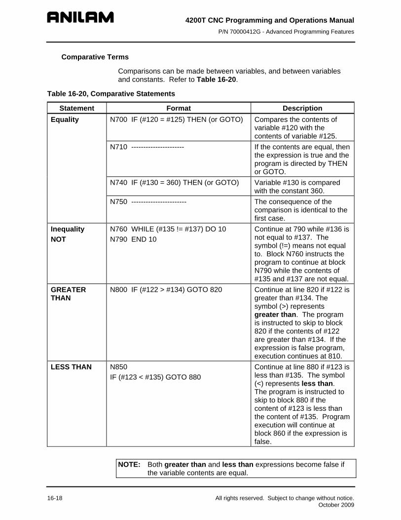
4200T CNC Programming and Operations Manual P/N 70000412G - Advanced Programming Features
16-18 All rights reserved. Subject to change without notice. October 2009
Comparative Terms
Comparisons can be made between variables, and between variables and constants. Refer to Table 16-20.
Table 16-20, Comparative Statements
Statement Format Description Equality N700 IF (#120 = #125) THEN (or GOTO) Compares the contents of
variable #120 with the contents of variable #125.
N710 ---------------------- If the contents are equal, then the expression is true and the program is directed by THEN or GOTO.
N740 IF (#130 = 360) THEN (or GOTO) Variable #130 is compared with the constant 360.
N750 ----------------------- The consequence of the comparison is identical to the first case.
Inequality NOT
N760 WHILE (#135 != #137) DO 10 N790 END 10
Continue at 790 while #136 is not equal to #137. The symbol (!=) means not equal to. Block N760 instructs the program to continue at block N790 while the contents of #135 and #137 are not equal.
GREATER THAN
N800 IF (#122 > #134) GOTO 820 Continue at line 820 if #122 is greater than #134. The symbol (>) represents greater than. The program is instructed to skip to block 820 if the contents of #122 are greater than #134. If the expression is false program, execution continues at 810.
LESS THAN N850 IF (#123 < #135) GOTO 880
Continue at line 880 if #123 is less than #135. The symbol (<) represents less than. The program is instructed to skip to block 880 if the content of #123 is less than the content of #135. Program execution will continue at block 860 if the expression is false.
NOTE: Both greater than and less than expressions become false if the variable contents are equal.

4200T CNC Programming and Operations Manual P/N 70000412G - Advanced Programming Features
All rights reserved. Subject to change without notice. 16-19 October 2009
File Inclusion
File inclusion is a function that allows a second program to be called or included in the program that is being run. If the function is encountered in a main program, the entire included program will be processed. The program will then continue running the original program. The function may also be placed after the end of the main program. It will then enable the use of an included subroutine.
Format ["FILENAME.G Open square bracket, double quote, filename and extension are
required.
Inclusion File Requirements
The program must exist in the current program directory.
The contents will vary depending on the intended use.
Inclusion File Formats
Typically, program lines that are to be included whenever the function is encountered, will not have an ending code, e.g. M2, M30 or M99. This would be useful when several program lines that never change are used several times in many programs. (see Toolchg.g)
Used as a subroutine that is accessible to all programs, the program would start with a program number (Onnn) and end with M99. The Include function statement must then be after the end of the main program. (after M2 or M30) The included subroutine then can be used by the main program as any other subroutine, using M98 Pnnn, G65 Pnnn, etc. (see Mysub.g)
Example Program N01 .... N02 .... N03 ["TOOLCHG.G Executes blocks in program Toolchg.g N04 ... N05 M98 P200 Executes included subroutine Mysub.g N06 ... N07 ["TOOLCHG.G Executes blocks in program Toolchg.g N08 ... N09 M2 End of program N10 ["MYSUB.G Includes subroutine Mysub.g Toolchg.g N01 ...... N02 .......

4200T CNC Programming and Operations Manual P/N 70000412G - Advanced Programming Features
N03 ....... No end of program used Mysub.g N01 O200 Subroutine format N02 .... N03 .... N04 .... N05 M99 End of subroutine
Sample Parametric Program
Refer to Figure 16-1. The diagram represents the part that will be programmed. Refer to Table 16-21. The program uses parametric programming features to create a G81 longitudinal grooving cycle.
W
B
X
Z
X0, Z0
Figure 16-1, G81 Longitudinal Grooving Cycle
Table 16-21, Parametric Programming Example
Program Body Comments N005 G90 G70 G0 TO X0 Z0
N010 G94 F20.0
N030 T1
N050 X2.1 Z-1.
N055 G65 P100 Z-.500 X-.500 W.200 *Calls Macro 100
N060 T0 G0 X0 Z0 *CNC returns here when the macro is completely executed.
N100 M2 *Ends main program
N105 O100 *Begin Macro for Canned Cycle *The O address word identifies the program as a macro (or subprogram).
*PARAMETERS PASSED *X #24 = depth of groove *External groove only. Z positioned at
start of groove. *Z #26 = width of groove *Groove size negative, Z moves
toward spindle.
16-20 All rights reserved. Subject to change without notice. October 2009

4200T CNC Programming and Operations Manual P/N 70000412G - Advanced Programming Features
All rights reserved. Subject to change without notice. 16-21 October 2009
Program Body Comments *W #23 = width of tool
*Groove size positive, Z moves away from spindle.
N125 #51 = .100 *Clearance distance for X.
N130 #23 = ABS (#23) *Tool width is absolute.
N135 #60 = 0 *Set variable for test. ( 0 for fail, 1 for pass).
N140 IF (#26 > 0) THEN *If groove direction (and size) is positive.
N145 #50 = #26 - #23 *Calculates stock left after one pass
N150 IF (#50 > 0 | #50 = 0) THEN; #60 = 1; ENDIF
*If STK (Stock Remaining) is greater than zero then pass test. If pass programs jumps to line 170.
N155 ELSE *If groove direction (and size) is negative.
N160 #50 = #26 + #23 *STK remaining after one pass
N165 IF (#50 < 0 | #50 = 0) THEN; #60 = 1; ENDIF
*If there is STK remaining or if STK = 0 then pass test, move to line 170
N170 ENDIF *Ends if statement from line 140
N175 IF (#60 = 0) THEN *program continues at line 190 if #60 != 0
N180 PRINT (TOOL IS WIDER THAN GROOVE!)
*Error Message
N185 M30 *Terminate subroutine
N190 ENDIF *Ends if statement from line 175
N195 #52 = #1012 + #50 *Absolute end position of groove width
N200 #86 = #1012; #87 = #1010 *Save current X and Z position
N205 IF (#24 < 0) THEN *If X depth is negative, set clearance negative
N210 #51 = -(#51) N215 ENDIF *Ends IF statement from line 205 N220 #53 = #51 +#24 *Total depth in X N225 #55 =FIX(ABS(#50/#23)) *Number of loops N230 IF ((#55*ABS(#23))= ABS(#50)) THEN; #55 = #55 -1 ENDIF
*Checks how many loops are needed to finish groove.
N235 #56 = #50/(#55+1) *Calculates distance to move along Z axis after each cut is made.
N240 G91 G01 X#53 *Cutting motion begins N245 G00 X(-#53) *Rapid out N250 LOOP #55 *#55= number of passes to cut N255 G91 G00 Z#56 *Move Z position one tool width over N260 G01 X#53 N265 G00 X(-#53) *Rapid out

4200T CNC Programming and Operations Manual P/N 70000412G - Advanced Programming Features
16-22 All rights reserved. Subject to change without notice. October 2009
Program Body Comments N270 END *End Loop N275 IF (#50 != 0) THEN N280 G90 G00 Z#52 N285 G91 G01 X#53 N290 G90 G00 X#87 Z#86 N295 ENDIF *Ends IF statement from line 275 N300 M99 *Ends macro, return to main program

4200T CNC Programming and Operations Manual P/N 70000412G - Machine Software and Peripherals Installation
All rights reserved. Subject to change without notice. 17-1 October 2009
Section 17 - Machine Software and Peripherals Installation
Passwords
The Setup Utility requires a password for restricted parameters. The CNC limited access password is 159. The service access password is Z48.
Machine Software Installation
The CNC software is installed when the machine is set up and during software updates.
To install the machine software, do the following:
1. In Manual Mode, press SHIFT + Exit (F10). The CNC's startup screen is displayed.
2. Highlight Setup Utility, and press ENTER. The Setup Menu is displayed.
3. Highlight Builder Setup, and press ENTER. The Builder Setup Menu is displayed.
4. Highlight Software Update, and press ENTER. The installation sequence begins.
5. Follow the instructions on the screen.
Printer Installation
The machine builder determines whether the system will support a printer option. To connect a printer, you must provide the cable and connect it to the DB-25 printer port on the machine. The connector is usually labeled “printer”.
Keyboard Installation
The machine builder determines whether the system will support a keyboard option. If the system supports a keyboard, plug the keyboard DIN connector into the side of the computer chassis, in the connector labeled "Keyboard". While the keyboard is installed, the console keypad remains inactive.
WARNING: There is no keyboard equivalent for the E-STOP. Therefore, emergency shutdowns (E-STOP) cannot be performed via keyboard. You must use the console E-STOP.
NOTE: Industrial grade keyboards are recommended for shop environments.

4200T CNC Programming and Operations Manual P/N 70000412G - Machine Software and Peripherals Installation
Keypad Equivalent Keyboard Keys
Refer to Table 17-1.
Table 17-1, Keyboard Equivalents
Function CNC Key Face Keyboard Keystroke Equivalent
CLEAR
Z
ARROWS
ARROWS
ENTER
ENTER
SHIFT
SHIFT
X (axis)
(X)
Y (axis) Y (Y)
Z
(ALT + C)
START
(ALT + S)
HOLD
(ALT + H)
Activate System
Information Screen
Refer to “Displaying System Information” in “Section 10 - Program Management.”
(ALT + I)
Activate Large Position Display
(B)
Switch to Rapid Override
(R + ENTER)
Activate IPI Monitor
(P)
17-2 All rights reserved. Subject to change without notice. October 2009

4200T CNC Programming and Operations Manual P/N 70000412G - Off-line Software Installation
All rights reserved. Subject to change without notice. 18-1 October 2009
Section 18 - Off-line Software The off-line version of the software requires an **Intel® based Personal Computer (PC) or 100% compatible. A minimum of 4MB of RAM is required. The hard disk drive must have a minimum of 4MB of space available.
The off-line software is also compatible with **Microsoft® **Windows® Operating Systems, such as **Windows NT®, Windows 95, Windows 98, or Windows 2000.
Passwords
Access to some parameters is restricted. Refer to Table 18-1. Where required, the CNC prompts the user to enter a password.
To access protected parameters:
1. Type the service password, and press ENTER. The CNC will enable you to change the protected settings.
2. There are four access levels protected by passwords. Operators are assigned limited passwords, which enable them to set parameters used in normal machine operations. Service passwords enable a higher level of access. The factory password is not used outside the manufacturer’s plant.
Table 18-1, Off-line Passwords
Restriction Level Password Limited access Q1 Service access Q2 Integrated Programmable Intelligence (IPI)
Q3
Exiting the Software
Press ESC to exit the software from the Main Menu selection screen.
- - - - - ** Intel® is a registered trademark of Intel Corporation in the United States and/or other
countries. ** Microsoft®, Windows®, and Windows NT® are registered trademarks of Microsoft
Corporation in the United States and/or other countries.

4200T CNC Programming and Operations Manual P/N 70000412G - Off-line Software Installation
18-2 All rights reserved. Subject to change without notice. October 2009
Windows Off-line Software Installation 1. Insert the installation disk in the floppy drive.
2. Go to the task bar, and click on the Start button. Select Run. The Run window activates.
3. In the Open entry field, type “A:setup”. Click on OK. The installation procedure will then begin.
4. Follow the on-screen prompts as they appear.
NOTE: Substitute “B:setup” for “A:setup” if your 3.5 inch floppy is in the B:drive.
Running Off-line Software from Windows 1. If you selected “Desktop Icon” (recommended) during the installation,
click the 4200T icon on your desktop. 2. If you selected Start Menu, start from there.
System Settings
Maximum Memory Allocated
In the Setup Utility, you can adjust the amount of memory allocated to the CNC software. Set the Maximum Memory Allocated parameter between 2 MB and 18 MB. This feature limits the amount of memory available to the software, preventing the CNC program from tapping into Windows’ large virtual memory supply. Allocating too much memory to the control software will dramatically increase startup time and make the software run slower.
To change the Maximum Memory Allocated parameter:
1. In the CNC’s startup screen, select Setup Utility, and press ENTER. The Setup Options menu is displayed.
2. Select Operator Setup, and press ENTER. The General Software menu is displayed.
3. Select Control Software, and press ENTER. The Control Software menu is displayed.
4. Select Maximum Memory Allocated, and press ENTER. Type the appropriate value, and press ENTER.
The only time it might be necessary to increase this parameter is when editing a program that is larger than this value. In this case, the CNC will generate an error message indicating that there is not enough memory to edit the program. To correct this problem, change this parameter to be the size of program plus 1MB.

4200T CNC Programming and Operations Manual P/N 70000412G - Off-line Software Installation
All rights reserved. Subject to change without notice. 18-3 October 2009
Disabled Features
The following software features, found in the Program Directory’s Utility (F9) pop-up are not available under any Windows operating system:
Check Disk Floppy Format Disk Optimization Program Restore
If you select one of these features, the CNC displays a message to inform you that the feature is disabled.


4200T CNC Programming and Operations Manual P/N 70000412G - Sample Programs
All rights reserved. Subject to change without notice. 19-1 October 2009
Section 19 - Sample Programs
Introduction
The following sample programs are examples of typical programming formats used in the 4200T CNC. The sample programs are included in your machine and offline installation disks.
All program blocks are commented. The comments are located to right of the asterisk (*) and are used to describe the program code and operations of that block.

4200T CNC Programming and Operations Manual P/N 70000412G - Sample Programs
Sample Program #1
One operation is required to complete this component. Part must be extended a minimum of 2.75 inches from chuck jaws with stock size 3.00 inches diameter.
Refer to Figure 19-1. The program shows a typical format used to face and turn a component. A sub-program is shown for the Area Clear Cycle (G73). The sub-program describes the Finish Profile of the component.
START POINT OF SUBPROG.
3.0" 1.00"
2.60"
0.10" x 45 Deg. Chamfer
2.50"0.10" x 45 Deg. Chamfer
1
END POINT OF SUB
2
4
TOOL REQUIRED
TOOL No.1ROUGH TURN
5
3
= START / END POINT OF EACH MOVE WITHIN THE CONTOUR
= START / END POINT OF SUB PROGRAM
Figure 19-1, Layout for Sample Program #1
19-2 All rights reserved. Subject to change without notice. October 2009
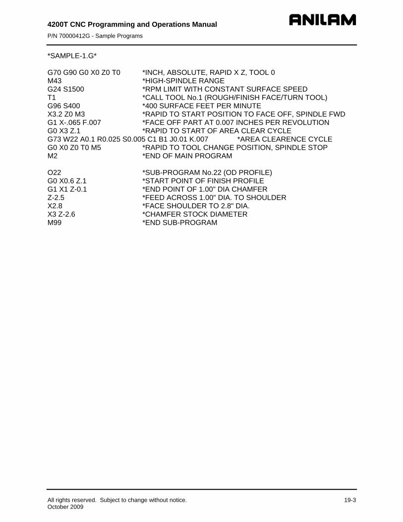
4200T CNC Programming and Operations Manual P/N 70000412G - Sample Programs
All rights reserved. Subject to change without notice. 19-3 October 2009
*SAMPLE-1.G* G70 G90 G0 X0 Z0 T0 *INCH, ABSOLUTE, RAPID X Z, TOOL 0 M43 *HIGH-SPINDLE RANGE G24 S1500 *RPM LIMIT WITH CONSTANT SURFACE SPEED T1 *CALL TOOL No.1 (ROUGH/FINISH FACE/TURN TOOL) G96 S400 *400 SURFACE FEET PER MINUTE X3.2 Z0 M3 *RAPID TO START POSITION TO FACE OFF, SPINDLE FWD G1 X-.065 F.007 *FACE OFF PART AT 0.007 INCHES PER REVOLUTION G0 X3 Z.1 *RAPID TO START OF AREA CLEAR CYCLE G73 W22 A0.1 R0.025 S0.005 C1 B1 J0.01 K.007 *AREA CLEARENCE CYCLE G0 X0 Z0 T0 M5 *RAPID TO TOOL CHANGE POSITION, SPINDLE STOP M2 *END OF MAIN PROGRAM O22 *SUB-PROGRAM No.22 (OD PROFILE) G0 X0.6 Z.1 *START POINT OF FINISH PROFILE G1 X1 Z-0.1 *END POINT OF 1.00" DIA CHAMFER Z-2.5 *FEED ACROSS 1.00" DIA. TO SHOULDER X2.8 *FACE SHOULDER TO 2.8" DIA. X3 Z-2.6 *CHAMFER STOCK DIAMETER M99 *END SUB-PROGRAM

4200T CNC Programming and Operations Manual P/N 70000412G - Sample Programs
Sample Program #2
One operation is required to complete this component. Part must be extended a minimum of 2.75 inches from chuck jaws with stock size 3.00 inches diameter.
Refer to Figure 19-2. The program below shows a typical format used to face and turn a component. A sub-program is shown for the Area Clear Cycle (G73). The sub-program describes the Finish Profile of the component.
TOOL REQUIRED
TOOL No.1ROUGH TURN
START POINT OF SUB PROG.
3.0" 1.00"
2.60"
0.10" x 45 Deg. Chamfer
2.50"0.10" x 45 Deg. Chamfer
1
END POINT OF SUBPROGRAM
23
6
1.85"
1.25"
4
5
= START / END POINT OF EACH MOVE WITHIN THE CONTOUR
= START / END POINT OF SUB PROGRAM
Figure 19-2, Layout for Sample Program #2
19-4 All rights reserved. Subject to change without notice. October 2009

4200T CNC Programming and Operations Manual P/N 70000412G - Sample Programs
All rights reserved. Subject to change without notice. 19-5 October 2009
*SAMPLE-2.G* G70 G90 G0 X0 Z0 T0 *INCH, ABSOLUTE, RAPID X Z, TOOL 0 M43 *HIGH SPINDLE RANGE G24 S1500 *RPM LIMIT WITH CONSTANT SURFACE SPEED T1 *CALL TOOL No.1 (ROUGH/FINISH FACE/TURN TOOL) G96 S400 *400 SURFACE FEET PER MINUTE X3.2 Z0 M3 *RAPID TO START POSITION TO FACE OFF, SPINDLE FWD G1 X-.065 F.007 *FACE OFF PART AT 0.007" PER REVOLUTION G0 X3 Z.1 *RAPID TO START OF AREA CLEAR CYCLE G73 W3 A.1 R.025 S.005 C1 B1 J.01 *AREA CLEARENCE CYCLE G0 X0 Z0 T0 M5 *RAPID TO TOOL CHANGE POSITION, SPINDLE STOP M2 *END OF MAIN PROGRAM O3 *SUB-PROGRAM NO.3 (OD PROFILE) G0 X0.6 Z.1 *START POINT OF FINISH PROFILE G1 X1 Z-0.1 *END POINT OF 1.00" DIA CHAMFER Z-1.25 *FEED ACROSS 1.00" DIA. TO START POINT OF ANGLE X1.85 Z-2.5 *FEED TO END POINT OF ANGLE X2.8 *FACE OUT TO START OF CHAMFER ON STOCK DIAMETER X3 Z-2.6 *CHAMFER STOCK DIAMETER M99 *END SUB-PROGRAM

4200T CNC Programming and Operations Manual P/N 70000412G - Sample Programs
Sample Program #3
One operation is required to complete this component. Part must be extended a minimum of 4.50 inches from chuck jaws with stock size 5.00 inches diameter.
Refer to Figure 19-3. The program below shows a typical format used to face and turn a component. A sub-program is shown for the Area Clear Cycle (G73). The sub-program describes the Finish Profile of the component. The sub-program uses the Blue Print Programming (available via the HELP menu) format to describe the Finish Profile. Blue Print Programming provides for stating multiple moves in the same block without having to calculate end points.
5.0" 2.00"
4.10"
0.10" x 45 Deg. Chamfer
4.00" 0.10" x 45 Deg. Chamfer
0.75" R
1
END POINT OF SUBPROGRAM
2
3
TOOL REQUIRED
TOOL No.1ROUGH TURN
4
= START / END POINT OF EACH MOVE WITHIN THE CONTOUR
= START / END POINT OF SUB PROGRAM
START POINT OF SUB PROG.
Figure 19-3, Layout for Sample Program #3
19-6 All rights reserved. Subject to change without notice. October 2009

4200T CNC Programming and Operations Manual P/N 70000412G - Sample Programs
All rights reserved. Subject to change without notice. 19-7 October 2009
*SAMPLE-3.G* G70 G90 G0 X0 Z0 T0 *INCH, ABSOLUTE, RAPID X Z, TOOL 0 M43 *HIGH SPINDLE RANGE G24 S1500 *RPM LIMIT WITH CONSTANT SURFACE SPEED T1 *CALL TOOL No.1 (ROUGH/FINISH, FACE/TURN TOOL) G96 S350 *350 SURFACE FEET PER MINUTE X5.2 Z0 M3 *RAPID TO START POSITION TO FACE OFF, SPINDLE FWD G1 X-.065 F.007 *FACE OFF PART AT 0.007" PER REVOLUTION G0 X5 Z.1 *RAPID TO START OF AREA CLEAR CYCLE G73 W1 A.1 R.025 S.005 C1 B1 J.01 *AREA CLEARENCE CYCLE G0 X0 Z0 T0 M5 *RAPID TO TOOL CHANGE POSITION, SPINDLE STOP M2 *END OF MAIN PROGRAM O1 *SUB-PROGRAM No.1 (OD PROFILE) G0 X1.6 Z.1 *START POINT OF FINISH PROFILE G1 X2 Z-0.1 *END POINT OF 1.00" DIA CHAMFER B180 | Q.75 B90 X4.8 Z-4 *TURN, RADIUS AND FACE TO GIVEN X,Z, END POINT X5 Z-4.1 *CHAMFER STOCK DIAMETER M99 *END SUB-PROGRAM

4200T CNC Programming and Operations Manual P/N 70000412G - Sample Programs
Sample Program #4
One operation is required to complete this component. Part must be extended a minimum of 4.50 inches from chuck jaws with stock size 4.50 inches diameter.
Refer to Figure 19-4. The program below shows a typical format used to face, rough and finish turn a component. A sub-program is shown for the Area Clear Cycle (G73). The sub-program describes the Finish Profile of the component. The sub-program uses the Blue Print Programming (available via the HELP menu) format to describe the Finish Profile. Blue Print Programming provides for stating multiple moves in the same block without having to calculate end points.
END POINT OF SUB PROGRAM
START POINT OF SUB PROG.
4.5" 1.00" 2.00" 4.00"
4.05"
0.05" x 45 Deg. Chamfer
4.00"
0.80"
0.05" x 45 Deg. Chamfer
3.50"
10 Degrees
45 Degrees
1
3
2
56
4
TOOLS REQUIRED
TOOL No.1ROUGH TURN
TOOL No.2FINISH TURN
= START / END POINT OF EACH MOVE WITHIN THE CONTOUR
= START / END POINT OF SUB PROGRAM
3.00"
Figure 19-4, Layout for Sample Program #4
19-8 All rights reserved. Subject to change without notice. October 2009

4200T CNC Programming and Operations Manual P/N 70000412G - Sample Programs
All rights reserved. Subject to change without notice. 19-9 October 2009
*SAMPLE-4.G* G70 G90 G0 X0 Z0 T0 *INCH, ABSOLUTE, RAPID X Z, TOOL 0 M43 *HIGH SPINDLE RANGE G24 S1800 *RPM LIMIT WITH CONSTANT SURFACE SPEED T1 *CALL TOOL NO.1 (FACE AND ROUGH TURN TOOL) G96 S400 *400 SURFACE FEET PER MINUTE X4.7 Z0 M3 *RAPID TO POSITION TO FACE OFF, SPINDLE FWD G1 G95 X-.065 F.006 M8 *FACE OFF AT 0.006" PER REV. COOLANT ON G0 X4.5 Z.1 *RAPID TO START POSN FOR AREA CLEAR. CYCLE G73 W1 A0.15 R0.02 S0.005 C0 B1 J0.015 K0.008 *AREA CLEARENCE CYCLE M5 *COOLANT OFF G0 X0 Z0 T0 M9 *RAPID TO TOOL CHANGE POSITION, SPINDLE OFF T2 *CALL TOOL NO.2 (FINISH TURN TOOL) M43 *HIGH SPINDLE RANGE G96 S450 *450 SURFACE FEET PER MINUTE G41 X.7 Z.1 M3 *TNC LEFT, RAPID POSN FOR FINISH PASS, SPINDLE FWD M98 P1 *CALL SUB-PROGRAM NO.1 FOR FINISH PASS G40 X4.7 M9 *CANCEL TNC, FEED OFF PART O.D. COOLANT OFF G0 X0 Z0 T0 M5 *RAPID TO TOOL CHANGE POSITION, SPINDLE OFF M2 *END MAIN PROGRAM O1 *SUB-PROGRAM O1 (OD PROFILE) G0 X.7 Z.1 *START POINT OF FINISH PROFILE G1 X1 Z-.05 *END POINT OF 1.00" CHAMFER B180 | B90 X2 Z-.8 *TURN 1.00" DIA. FACE OUT TO 2.00" DIA. B170 | B90 X3.5 Z-3 *TURN ANGLE, FACE OUT TO 3.5" DIA. B135 | B180 X4 Z-4 *TURN 45 DEGREE ANGLE AND 4.00" DIA. B90 | B135 X4.5 Z-4.05 *FACE OUT AND CHAMFER 4.5" DIA. M99 *END OF SUB-PROGRAM

4200T CNC Programming and Operations Manual P/N 70000412G - Sample Programs
Sample Program #5
One operation is required to complete this component. Part must be extended a minimum of 4.50 inches from chuck jaws with stock size 5.00 inches diameter.
Refer to Figure 19-5. The program below shows a typical format used to face, rough and finish turn a component. A sub-program is shown for the Area Clear Cycle (G73). The sub-program describes the Finish Profile of the component. The sub-program uses the Blue Print Programming (available via the HELP menu) format to describe the Finish Profile. Blue Print Programming provides for stating multiple moves in the same block without having to calculate end points.
END POINT OF SUBPROGRAM
START POINT OF SUB PROG.
5.0" 2.00" 4.00"
4.10"
0.05" x 45 Deg. Chamfer
4.00"3.00"
0.10" x 45 Deg. Chamfer
25 Degrees
1.25"
0.060" R
0.10" R 0.20" R
123
4
56
7
TOOLS REQUIRED
TOOL No.1ROUGH TURN
TOOL No.2FINISH TURN
8
= START / END POINT OF EACH MOVE WITHIN THE CONTOUR
= START / END POINT OF SUB PROGRAM
1.00"
2.00"
Figure 19-5, Layout for Sample Program #5
19-10 All rights reserved. Subject to change without notice. October 2009
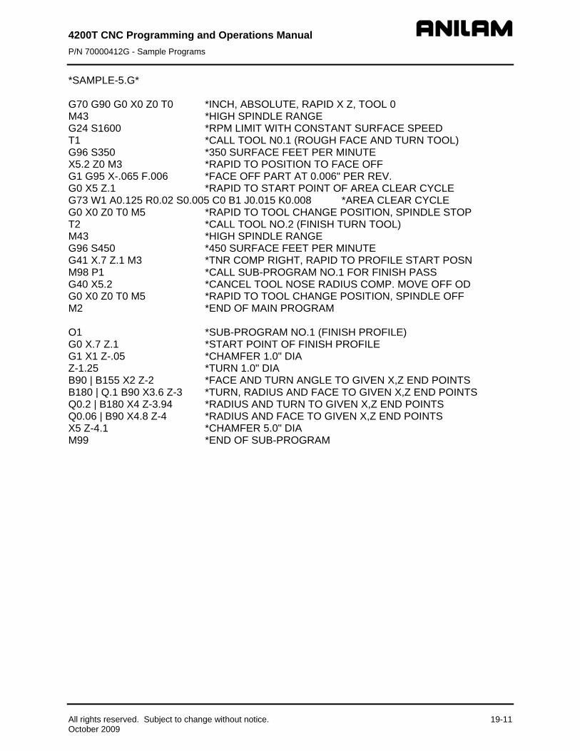
4200T CNC Programming and Operations Manual P/N 70000412G - Sample Programs
All rights reserved. Subject to change without notice. 19-11 October 2009
*SAMPLE-5.G* G70 G90 G0 X0 Z0 T0 *INCH, ABSOLUTE, RAPID X Z, TOOL 0 M43 *HIGH SPINDLE RANGE G24 S1600 *RPM LIMIT WITH CONSTANT SURFACE SPEED T1 *CALL TOOL N0.1 (ROUGH FACE AND TURN TOOL) G96 S350 *350 SURFACE FEET PER MINUTE X5.2 Z0 M3 *RAPID TO POSITION TO FACE OFF G1 G95 X-.065 F.006 *FACE OFF PART AT 0.006" PER REV. G0 X5 Z.1 *RAPID TO START POINT OF AREA CLEAR CYCLE G73 W1 A0.125 R0.02 S0.005 C0 B1 J0.015 K0.008 *AREA CLEAR CYCLE G0 X0 Z0 T0 M5 *RAPID TO TOOL CHANGE POSITION, SPINDLE STOP T2 *CALL TOOL NO.2 (FINISH TURN TOOL) M43 *HIGH SPINDLE RANGE G96 S450 *450 SURFACE FEET PER MINUTE G41 X.7 Z.1 M3 *TNR COMP RIGHT, RAPID TO PROFILE START POSN M98 P1 *CALL SUB-PROGRAM NO.1 FOR FINISH PASS G40 X5.2 *CANCEL TOOL NOSE RADIUS COMP. MOVE OFF OD G0 X0 Z0 T0 M5 *RAPID TO TOOL CHANGE POSITION, SPINDLE OFF M2 *END OF MAIN PROGRAM O1 *SUB-PROGRAM NO.1 (FINISH PROFILE) G0 X.7 Z.1 *START POINT OF FINISH PROFILE G1 X1 Z-.05 *CHAMFER 1.0" DIA Z-1.25 *TURN 1.0" DIA B90 | B155 X2 Z-2 *FACE AND TURN ANGLE TO GIVEN X,Z END POINTS B180 | Q.1 B90 X3.6 Z-3 *TURN, RADIUS AND FACE TO GIVEN X,Z END POINTS Q0.2 | B180 X4 Z-3.94 *RADIUS AND TURN TO GIVEN X,Z END POINTS Q0.06 | B90 X4.8 Z-4 *RADIUS AND FACE TO GIVEN X,Z END POINTS X5 Z-4.1 *CHAMFER 5.0" DIA M99 *END OF SUB-PROGRAM

4200T CNC Programming and Operations Manual P/N 70000412G - Sample Programs
Sample Program #6
One operation is required to complete this component. Part must be extended a minimum of 4.50 inches from chuck jaws with stock size 5.00 inches diameter.
Refer to Figure 19-6. The program below shows a Program to face, center drill, drill and rough and finish bore a component. A Sub-Program is shown for the Area Clear Cycle (G73). The Sub-Program describes the Finish Profile of the component. All TEXT to the right of the star (*) are ignored when running the program and are only shown to describe the Program code and operations on that block.
= START / END POINT OF EACH MOVE WITHIN THE CONTOUR
= START / END POINT OF SUB PROGRAM
TOOL REQUIRED
1.00"
1.0" DRILL THRU' 3.50"
2
0.125" x 45 Deg. Chamfer
43
6
5
1
7
1.125"
TOOL No.1ROUGH TURN
TOOL No.2CENTER DRILL
TOOL No.31.00" DIA. DRILL
TOOL No.4ROUGH / FINISH BORE
Figure 19-6, Layout for Sample Program #6
19-12 All rights reserved. Subject to change without notice. October 2009

4200T CNC Programming and Operations Manual P/N 70000412G - Sample Programs
All rights reserved. Subject to change without notice. 19-13 October 2009
*SAMPLE-6.G* G70 G90 G0 X0 Z0 T0 *INCH, ABSOLUTE, RAPID X Z, TOOL 0 M43 *HIGH SPINDLE RANGE G24 S1600 *RPM LIMIT WITH CONSTANT SURFACE SPEED T1 *CALL TOOL NO.1 (FACING TOOL) G96 S400 *400 SURFACE FEET PER MINUTE X3.7 Z0 M3 *RAPID TO POSITION TO FACE OFF G1 X-.065 G95 F.006 M8 *FACE OFF AT 0.006" PER REV. COOLANT ON G0 Z.1 M5 *RAPID OFF FRONT FACE, SPINDLE OFF X0 Z0 T0 M9 *RAPID TO TOOL CHANGE POSITION, COOLANT OFF T2 *CALL TOOL NO.2 (CENTER DRILL) M42 *MID SPINDLE RANGE G97 S500 *500 RPM X0 Z.1 M3 *RAPID TO PART CENTER, 0.1 FROM FRONT FACE G1 Z-.275 M8 F.005 *CENTERDRILL TO DEPTH AT 0.005" PER REV. COOLANT ON G0 Z.1 M9 *RAPID OUT OF CENTERDRILLED HOLE, COOLANT OFF X0 Z0 T0 M5 *RAPID TO TOOL CHANGE POSITION, SPINDLE OFF T3 *CALL TOOL NO.3 (1.0" DIA DRILL) M42 *MID SPINDLE RANGE G97 S500 *500 RPM X0 Z.1 M3 *RAPID TO PART CENTER, 0.1" FROM FACE, SPINDLE FWD M8 *COOLANT ON G78 Z-3 R0.1 F0.005 I0.3 *PECK DRILLING CANNED CYCLE M9 *COOLANT OFF G0 X0 Z0 T0 M5 *RAPID TO TOOL CHANGE POSITION, SPINDLE OFF T4 *CALL TOOL NO.4 (ROUGH/FINISH BORING BAR) M43 *HIGH SPINDLE RANGE G96 S375 *375 SURFACE FEET PER MINUTE X1 Z.1 M3 *RAPID TO START POINT OF CLEAR.CYCLE, SPINDLE FWD M8 *COOLANT ON G73 W1 A0.1 R0.02 S0.005 C1 B0 J0.012 K0.007 *AREA CLEARENCE CYCLE G0 Z.1 M9 *RAPID CLEAR OF BORE, COOLANT OFF X0 Z0 T0 M5 *RAPID TO TOOL CHANGE POSN. SPINDLE OFF M2 *END MAIN PROGRAM O1 *SUB-PROGRAM O1 (ID PROFILE) G0 X3.95 Z.1 *START POINT OF FINISH PROFILE G1 X3.5 Z-.125 *CHAMFER 3.5" ID Z-1 *BORE 3.5" DIA X2.75 *FACE TO 2.75" ID Z-1.125 *BORE 2.75" ID X1 *FACE DOWN TO DRILL DIA. M99 *END SUB-PROGRAM

4200T CNC Programming and Operations Manual P/N 70000412G - Sample Programs
Sample Program #7
One operation is required to complete this component. Part must be extended a minimum of 4.50 inches from chuck jaws with stock size 4.50 inches diameter.
Refer to Figure 19-7. The program below shows a typical format to face, turn and OD thread a component. A Sub-Program is shown for the Area Clear Cycle (G73). The Sub-Program describes the Finish Profile of the component.
4.5"
4.05"
4.00"0.05" x 45 Deg. Chamfer
0.10" x 45 Deg. Chamfer
TOOLS REQUIREDOPERATION No.1
TOOL No.2 O.D. THREAD
TOOL No.1ROUGH TURN
3.00" x 10
3.50"
Figure 19-7, Layout for Sample Program #7
19-14 All rights reserved. Subject to change without notice. October 2009

4200T CNC Programming and Operations Manual P/N 70000412G - Sample Programs
All rights reserved. Subject to change without notice. 19-15 October 2009
*SAMPLE-7.G* G70 G90 G0 X0 Z0 T0 *INCH, ABSOLUTE, RAPID X Z, TOOL 0 M43 *HIGH SPINDLE RANGE G24 S1600 *RPM LIMIT WITH CONSTANT SURFACE SPEED T1 *CALL TOOL NO.1 (ROUGH/FINISH FACE/TURN TOOL) G96 S400 *400 SURFACE FEET PER MINUTE X4.7 Z0 M3 *RAPID POSITION TO FACE OFF, SPINDLE FORWARD M8 *COOLANT ON G1 X-.065 G95 F.007 *FACE OFF AT 0.007" INCH PER REV. G0 X4.5 Z.1 *RAPID POSITION FOR AREA CLEAR. CYCLE G73 W10 A.1 R.02 S.005 C1 B1 J.015 K.008 *AREA CLEAR. CYCLE G0 X0 Z0 T0 M9 *RAPID TO TOOL CHANGE POSITION, COOLANT OFF M5 *SPINDLE STOP T2 *CALL TOOL NO.2 (THREADING TOOL) M42 *MID SPINDLE RANGE G97 S500 *500 RPM X3.2 Z.5 M3 G95 F.04 *RAPID POSN FOR THD CYCLE, SET FEED 0.04" PER REV M8 *COOLANT ON G83 E10 Z-4 C-0.015 S2 R-0.1 *THREADING CANNED CYCLE G0 X0 Z0 T0 M9 *RAPID TO TOOL CHANGE POSITION, COOLANT OFF M5 *SPINDLE OFF M2 *END OF MAIN PROGRAM O10 *SUB-PROGRAM NO.10 (OD PROFILE) G0 X2.6 Z.1 *START POSITION OF FINISH PROFILE G1 X3 Z-.1 *CHAMFER 3" DIAMETER Z-4 *TURN 3" DIAMETER X4.4 *FACE OUT TO 4.4" DIA. X4.5 Z-4.05 *CHAMFER 4.5" DIAMETER M99 *END OF SUB-PROGRAM

4200T CNC Programming and Operations Manual P/N 70000412G - Sample Programs
Sample Program #8
One operation is required to complete this component. Part must be extended a minimum of 5.00 inches from chuck jaws with stock size 5.00 inches diameter.
Refer to Figure 19-8. The program below shows a typical format to face, rough and finish turn and groove (in multiple places) using an incremental Sub-Program. A Sub-Program is also shown for the Area Clear Cycle (G73). The Sub-Program describes the Finish Profile of the component. The Sub-Program uses the Blue Print Programming (available via the HELP menu) format to describe the Finish Profile. Blue Print programming provides for stating multiple moves in the same block without having to calculate end points.
4.75"0.125" x 45 Deg. Chamfer 4.35"
3.60"3.00"
2.75"
5.00" 1.50" 2.50"
45 o
GROOVE DETAILTYP. (5 PLACES)
0.025" x 45 Deg.Chamfer 0.125"
0.10"
1.50" 0.75"
2.25"
0.125" x 45 Deg. Chamfer
TOOLS REQUIRED FOR OPERATION No.1
TOOL No.1ROUGH TURN
TOOL No.31/8" GROOVE
Figure 19-8, Layout for Sample Program #8
19-16 All rights reserved. Subject to change without notice. October 2009

4200T CNC Programming and Operations Manual P/N 70000412G - Sample Programs
All rights reserved. Subject to change without notice. 19-17 October 2009
*SAMPLE-8.G* G70 G90 G0 X0 Z0 T0 *INCH, ABSOLUTE, RAPID X Z, TOOL 0 M42 *MID-SPINDLE RANGE G24 S1800 *RPM LIMIT WITH CONSTANT SURFACE SPEED T1 *CALL TOOL NO.1 (ROUGH/FINISH FACE/TURN TOOL) G96 S550 *550 SURFACE FEET PER MINUTE X5.2 Z0 M3 *RAPID POSITION TO FACE OFF, SPINDLE FORWARD G1 X-.04 G95 F.01 *FACE OFF AT 0.01" PER REV. G0 X5 Z.1 *RAPID POSITION TO START OF AREA CLEAR.CYCLE G73 W1 A0.15 R.02 S.005 C1 B1 J.015 K.008 *AREA CLEAR.CYCLE G0 X0 Z0 T0 M5 *RAPID TO TOOL CHANGE POSITION, SPINDLE OFF M43 *HIGH SPINDLE RANGE T2 *CALL TOOL NO.2 (1/8" WIDE GROOVE TOOL) G96 S650 M3 *650 SURFACE FEET PER MINUTE G0 X1.7 Z-.75 G95 F.003 *RAPID POSITION FOR 1ST GROOVE ON 1.5" DIA. G95 F.003 *SET FEEDRATE TO 0.003" PER REV. M98 P99 *CALL SUB-PROGRAM NO.99 (GROOVING ROUTINE) G0 Z-1.5 *RAPID POSITION FOR 2ND GROOVE ON 1.5" DIA. M98 P99 *CALL SUB-PROGRAM NO.99 (GROOVING ROUTINE) G0 Z-2.25 *RAPID POSITION FOR 3RD GROOVE ON 1.5" DIA. M98 P99 *CALL SUB-PROGRAM NO.99 (GROOVING ROUTINE) G0 X2.7 *RAPID POSITION X AXIS FOR GROOVES ON 2.5" DIA. Z-3.6 *RAPID POSITION Z AXIS FOR 1ST GROOVE ON 2.5" DIA. M98 P99 *CALL SUB-PROGRAM NO.99 (GROOVING ROUTINE) G0 Z-4.35 *RAPID POSITION FOR 2ND GROOVE ON 2.5" DIA. M98 P99 *CALL SUB-PROGRAM NO.99 (GROOVING ROUTINE) G0 X0 Z0 T0 M5 *RAPID TO TOOL CHANGE POSITION, SPINDLE OFF M2 *END OF MAIN PROGRAM O1 *SUB-PROGRAM NO.1 (OD CONTOUR) G0 X1.05 Z.1 *START POINT OF FINISH CONTOUR G1 X1.5 Z-.125 *CHAMFER 1.5" DIAMETER B180 | B90 X2 Z-2.75 *TURN 1.5" DIA. AND FACE OUT TO 2.0" DIA B135 | B180 X2.5 Z-4.75 *TURN 45 DEGREE ANGLE AND 2.5" DIA. B90 | B135 X5 Z-4.85 *FACE OUT AND CHAMFER 5.0" DIAMETER M99 *END OF SUB-PROGRAM O99 *SUB-PROGRAM NO.99 (GROOVING ROUTINE) G91 G1 X-.4 *INCREMENTAL, FEED TO GROOVE DEPTH G0 X.22 *RAPID OUT OF GROOVE Z-.035 *POSITION FOR LEFT SIDE CHAMFER G1 X-.07 Z.035 *45 DEGREE CHAMFER G0 X.07 *RAPID OUT OF GROOVE Z.035 *POSITION FOR RIGHT SIDE CHAMFER G1 X-.07 Z-.035 *45 DEGREE CHAMFER G0 X.25 *RAPID TO ORIGINAL START POSITION G90 *ABSOLUTE MODE M99 *END OF SUB-PROGRAM

4200T CNC Programming and Operations Manual P/N 70000412G - Sample Programs
Sample Program #9
One operation is required to complete this component. Part must be extended a minimum of 10.5 inches from chuck jaws; support with live center stock size 3.00 inches diameter by 12.5 inches long.
Refer to Figure 19-9. The program below shows a typical format to rough and finish turn a shaft component (including grooving and threading). A Sub-Program is shown for the Area Clear Cycle (G73). The Sub-Program describes the Finish Profile of the component. The Sub-Program uses the Blue Print Programming (available via the HELP menu) format to describe the Finish Profile. Blue Print Programming provides for stating multiple moves in the same block without having to calculate end points. Sub-Program O2 describes the groove profile, this is written in a sub-program so that multiple grooves can be machined.
TOOL No.3 1/8" GROOVE
TOOL No.4 O.D. THREAD
TOOLS REQUIRED
TOOL No.1ROUGH TURN
TOOL No.2FINISH TURN
GROOVETYP. (4
0.025" x 45Chamfer. 0.125"
0.10"
3.00"STOC
1.75"
1.375" Rad
1.00"
8.000"
10 Deg.
0.1" x 45Chamfer
0.05" x 45 Deg.Chamfer(2 Places)
10.000
6.000"
1.750"
1.125"
2.1214
1.25"
3.500"
4.000"
4.500"
5.000"
Figure 19-9, Layout for Sample Program #9
19-18 All rights reserved. Subject to change without notice. October 2009

4200T CNC Programming and Operations Manual P/N 70000412G - Sample Programs
All rights reserved. Subject to change without notice. 19-19 October 2009
*SAMPLE-9.G* G70 G90 G0 X0 Z0 T0 *INCH, ABSOLUTE, RAPID X Z, TOOL 0 M43 *HIGH SPINDLE RANGE G24 S1600 *RPM LIMIT WITH CONSTANT SURFACE SPEED T1 *CALL TOOL NO.1 (ROUGH TURN TOOL) G96 S400 *400 SURFACE SPEED PER MINUTE X3 Z.1 M3 *RAPID TO START POINT OF AREA CLEAR CYCLE G73 W1 A0.15 R.02 S.01 C0 B1 P1 I.005 J.012 *AREA CLEARENCE CYCLE G0 X0 Z0 T0 M5 *RAPID TO TOOL CHANGE POSITION, SPINDLE OFF T2 *CALL TOOL NO.2 (FINISH TURN TOOL) M43 *HIGH SPINDLE RANGE G24 S1800 *RPM LIMIT WITH CONSTANT SURFACE SPEED G96 S475 *475 SURFACE SPPED PER MINUTE G41 G0 X.6 Z.1 M3 G95 F.008 * TNR COMP. LEFT, RAPID TO START POINT, SPD FWD M98 P1 *CALL SUB-PROGRAM NO.1 (OD PROFILE) G40 X3.2 *CANCEL TNR COMP. MOVE OFF PART DIAMETER G0 X0 Z0 T0 M5 *RAPID TO TOOL CHANGE POSITION, SPINDLE OFF T3 *CALL TOOL NO.3 (1/8" WIDE GROOVE TOOL) M43 *HIGH SPINDLE RANGE G97 S750 *750 RPM X1.45 Z-3.5 M3 *RAPID POSITION FOR 1ST GROOVE, SPINDLE FORWARD M98 P2 *CALL SUB-PROGRAM NO.2 (GROOVING SUB-PROGRAM) G0 Z-4 *RAPID POSITION FOR 2ND GROOVE M98 P2 *CALL SUB-PROGRAM NO.2 (GROOVING SUB-PROGRAM) G0 Z-4.5 *RAPID POSITION FOR 3RD GROOVE M98 P2 *CALL SUB-PROGRAM NO.2 (GROOVING SUB-PROGRAM) G0 Z-5 *RAPID POSITION FOR 4TH GROOVE M98 P2 *CALL SUB-PROGRAM NO.2 (GROOVING SUB-PROGRAM) G0 X0 Z0 T0 M5 *RAPID TO TOOL CHANGE POSITION, SPINDLE OFF T4 *CALL TOOL NO.4 (SINGLE POINT THREADING TOOL) M43 *HIGH SPINDLE RANGE G97 S675 *675 RPM X1.2 Z.2 *RAPID TO START POSITION FOR THREADING CYCLE G83 E16 Z-1.125 C-.018 D-.042 A60 S2 R-.1 *THREADING CANNED CYCLE G0 X0 Z0 T0 M5 *RAPID TO TOOL CHANGE POSITION, SPINDLE OFF M2 *END OF MAIN PROGRAM O1 *SUB-PROGRAM NO.1 (OD PROFILE) G0 X0.6 Z.1 *START POINT OF FINISH PROFILE G1 X1 Z-.1 *CHAMFER 1.0" DIA. B180 | B170 X1.25 Z-1.75 *TURN AND 10 DEGREE ANGLE TO GIVEN X,Z, END POINTS Z-6 *TURN 1.25" GROOVE DIAMETER B90 | B135 X1.75 Z-6.05 *FACE AND CHAMFER 1.75" DIA. Z-6.9393 *TURN TO START OF 1.375" RADIUS G2 X1.75 Z-9.0607 R1.375 *TURN 1.375" RADIUS G1 Z-10 *TURN 1.75" DIAMETER B90 | B135 X3 Z-10.1 *FACE AND CHAMFER 3" DIAMETER M99 *END OF SUB-PROGRAM O2 *SUB-PROGRAM NO.2 (GROOVING SUB-PROGRAM)

4200T CNC Programming and Operations Manual P/N 70000412G - Sample Programs
19-20 All rights reserved. Subject to change without notice. October 2009
G1 X1.05 *FEED TO GROOVE DEPTH G4 T2 *DWELL AT BOTTOM OF GROOVE (2 SECONDS) G0 X1.27 *RAPID OUT OF THE GROOVE G91 Z-.035 *INCREMENTAL, POSITION FOR LEFT GROOVE CHAMFER G1 X-.07 Z.035 *CHAMFER LEFT SIDE OF GROOVE G90 G0 X1.27 *ABSOLUTE, RAPID OUT OF THE GROOVE G91 Z.035 *INCREMENTAL, POSITION FOR RIGHT GROOVE CHAMFER G1 X-.07 Z-.035 *CHAMFER RIGHT SIDE OF GROOVE G90 G0 X1.45 *ABSOLUTE, RAPID TO GROOVE START POSN M99 *END OF SUB-PROGRAM

4200T CNC Programming and Operations Manual P/N 70000412G - Index
All rights reserved. Subject to change without notice. Index-1 October 2009
% (RPM), machine status display, 3-5 % Feed, machine status display, 3-5 .G extension, 10-1, 10-2, 10-3 .S files, 10-14 4200T CNC Setup Utility Manual, P/N
70000414, referenced, 5-32
A abbreviating statements
description, 6-9, 16-16 listed, 6-9
absolute mode (G90), 4-22 activating Absolute, (G90), 13-12 description, 1-5, 3-10
absolute zero defined, 3-10 preset (G92) listing, 4-24 reference point, 1-5, 3-10
accessing communication software, 15-2 geometry tools, 14-16 most recently used programs, 6-16
activate background mode, 11-10 geometry elements, 14-29
activating manual mode, feed, 3-8 manual mode, rapid, 3-8 servos, 3-7 shape editor, 14-2 shapes, 14-16 test link screen, 15-5
active soft key, manual screen area, 3-5 acute angles, compensation, around, 9-21 adjusting
Draw display, 8-8 feedrate, 3-8 fixture offsets, in a table, 4-15 rapid move speed, 3-9
advanced programming features block, separators, 16-1 modifiers, description, 16-1 modifiers, listed, 16-1 probe move (G31), 16-13
advancing to beginning or end of a block, 6-6 to first or last block of a program, 6-6
alphanumeric keys illustration, 2-2
listed, 2-3 angular motion programming, example, 4-5 applications, parametric programming,
16-10 arc
move, input labels, listed, 13-6, 13-7 reversing, direction, 14-13 to cut, 13-17
arc tools description, 14-8 rounding tool, description, 14-9 template table, 14-8
ARCS Help Template Menu, 7-17 ARROW keys, 2-5 ASCII, data type, 15-4 auto mode
program, cancel, 11-5 program, hold, 11-5 program, to run, 11-4 screen, illustration, 11-4 starting block, select
using arrow keys, 11-5 using SEARCH, 11-5
switch from, single-step mode, 11-3 automatic mode, defined, 11-1 automatic, Draw restart, 8-7 axes, direction of motion, illustration, 1-2 axis
descriptions, 1-2 select key, illustration, 3-2 selecting, 3-11
B background mode
description, 11-10 to activate, 11-10
backing up, shapes, 14-32 baud rate, setting, 15-3 bi-directional
cutting radial threads, (G86), 5-26 longitudinal threading cycle, (G84), 5-20
BINARY, data type, 15-4 Blank Entry Fields, 7-13 Blank fields, 7-13 BLK, program area label, 3-6 block
advancing, to beginning or end of, 6-6 number, program area label, 3-6 restoring, 6-8 selected, run Draw, 8-7

4200T CNC Programming and Operations Manual P/N 70000412G - Index
Index-2 All rights reserved. Subject to change without notice. October 2009
separators, description, 16-1 skip variables, description, 16-5 skip variables, listed, table, 16-5 skips, setting selective, 16-6
blocks, writing, to another program, 6-13 boring cycle, (G88), 5-30 Both, Draw, description, 8-5
C Calibrate X TLO, 9-5 Calibrate Z TLO, 9-5 call statements, description, 16-10 cancel
auto mode program, 11-5 Draw, program, 8-3 In-Position Mode, modal, exact stop
check, (G64), 4-10 single-step run, execution, 11-2
canceling edits to a program block, 6-10 tool nose radius (TNR), 9-17 unsaved edits, 6-17
canned cycle cutting
longitudinal threads, (G83, uni-directional), 5-18
longitudinal threads, (G84, bi-directional), 5-20
radial threads, (G85, uni-directional), 5-23
radial threads, (G86, bi-directional), 5-26
lathe tool probe cycles description, 5-32 G-codes, designations, 5-35 macro variable, settings, 5-33 system variable, settings, 5-33
programming boring cycle, (G88), 5-30 chip break cycle, (G79), 5-12 longitudinal grooving cycle, (G81), 5-13 pecking cycle, (G78), 5-11 radial grooving cycle, (G82), 5-15 X-axis, radial (facing) roughing cycle,
(G77), 5-9 X-axis, facing/boring cycle with defined
profile, (G74), 5-4 Z-axis, rough turning or boring cycle,
(G76), 5-7 Z-axis, turning/boring cycle
longitudinal, (G73), 5-1
tapping a hole, (G87), 5-28 C-axis programming
description, 12-3 disabling, 12-3 enabling, 12-3 feedrate, 12-4 jog, to position, 12-4 synchronize/unsynchronize, 12-4
C-axis, description, 1-2 chaining, geometry elements to create a
shape, 14-26 chamfer, cutting, 13-16 chamfer, positive and negative, illustration,
13-16 chamfering rounding, modal, (G59 En), 4-16 chamfering, corners, 14-9 change word, feature description, 6-8 change, scales, 8-1 changing
fixture offsets, in a table, 4-15 fixture offsets, using calibrate keys, 4-16 jog mode, 3-11 link test link screen data display, 15-5 shape editor view, 14-15 the numbers, of look ahead blocks, 9-22 TNR compensation, in a program, 9-18
chip break cycle, (G79), 5-12 choosing correct, TNR compensation, 9-18 circle tools
description, 14-19 templates, listed, 14-19
circular interpolation absolute mode, 4-7 incremental mode, 4-8 parameters, 4-6 partial arc, description, 4-8
CLEAR key, 2-5 clear, (M9351 X302), 12-3 clearing
a halted program, 11-5 entries, 2-7 messages, 2-8 receive area, 15-6 transmit area, 15-6
CLEARING, help template menu, 7-31 clockwise motion (G2), description, 4-6 CNC
enlarged motion display, to set, 11-6 parts counter, description, 11-9 timer, description, 11-9
codes, order of execution, 12-3

4200T CNC Programming and Operations Manual P/N 70000412G - Index
All rights reserved. Subject to change without notice. Index-3 October 2009
COM1, 15-3 COM2, 15-3 Comm Port, selecting, 15-3 command line, manual screen area, 3-4 COMMAND, program area label, 3-6 Commanding Moves in SCI Mode, 13-5 comments, including in a program listing,
6-17 common (global) variables, description,
16-4 communication
description, 15-1 parameters, setting, 15-3 port, to select, 15-3 screen layout, description, 15-2 screen, illustration, 15-2 software, accessing, 15-2
Communications, 15-2 comparative terms, description, 16-18 compensation
around acute angles, 9-21 left, 9-9 right, 9-9
COMPENSATION, help template menu, 7-14
completed program, 3-6 conditional statements, listed, 16-14 console, illustration, 2-1 constant surface speed. See CSS construction geometry
creating, 14-20 using, 14-16
Cont (F10), 2-8 continuous
jog, 3-8 jog, Feed mode, 3-11 jog, Rapid mode, 3-11 move, execute, 3-12
contouring mode (cutter mode), (G64), 4-19 control M-codes
description, 12-2 functions, table, 12-2
conventional jog, 3-8 conventional jog mode, 3-11 coolant off, (M9), 12-2 coolant on, (M8), 12-2 coolant ready, 3-3 copy
programs, other directories, 10-10 programs, to floppy disk, 10-6
copying, program blocks, 6-11
corner rounding cancel, modal, (G60), 4-18 modal, (G59 Rn), 4-16
corners chamfering, 14-9 restoring, sharp, 14-14 rounding, 14-9
counterclockwise motion (G3), description, 4-6
create new programs, 10-2 subdirectory, 10-11
Create (F2), 10-2 creating, basic shape, 14-10 CSS mode, to set, 13-13 current, operating mode, 3-6 cursor, edit screen, location, 6-2 cursors, 2-7 cutting
a chamfer, 13-16 a radius, 13-17 a tapper, 13-15 feedrates in FPM, G94, 4-25 feedrates in FPR, G95, 4-25 longitudinal threads, (G83, uni-
directional), 5-18 longitudinal threads, (G84, bi-directional),
5-20 radial threads, (G85, uni-directional), 5-23 radial threads, (G86, bi-directional), 5-26 threads (G83), 13-11 threads, input label, listed, 13-11
D data bits, to set, 15-4 data control codes
function, table, 15-8 receive mode, to use, 15-8 send mode, to use, 15-8 to use, 15-8
data link, testing, 15-5 data type, to set, 15-4 date and time, 10-1 DE-9, 15-1 deactivate, geometry elements, 14-29 deactivating, shapes, 14-16 Decimal Points, 7-13 Default Feedrate, 3-9 Del (F4), 2-8

4200T CNC Programming and Operations Manual P/N 70000412G - Index
Index-4 All rights reserved. Subject to change without notice. October 2009
delete groups of programs, 10-6 program on another drive, 10-12 text, 2-8
Delete (F3), 10-3 deleting
a character, 6-4 a program block, 6-5 a segment, 14-15 a shape, 14-13 all geometry elements, 14-29 geometry elements, 14-28 shape files, 14-32
developing, part programs, 1-7 DIA, machine status display, 3-5 diameter programming, description, 1-6 direct transfer, variables, 16-7 disabled, features, off-line, 18-4 disclaimer, iii disengage, servos, 3-7 disk optimizer, to access, 10-13 display
Draw adjusting, 8-8 Draw, fit window, 8-9 Draw, scale, 8-9 erase, 8-7, 8-10 zoom, 8-10
DISPLAY (F5), description, 8-2 display size
change, 8-11 half, 8-9
distance to go, manual screen area, 3-5 Draw
Auto mode, 8-6 display size, double, 8-9 display size, half, 8-9 display size, scale, 8-9 display, adjusting, 8-8 display, erase, 8-10 display, fit window, 8-9 end at, specific block, 8-8 erase display, 8-7 grid parameter, to set, 8-5 grid size, to set, 8-6 Motion mode, 8-6 parameters, viewing, 8-4 rapid moves, description, 8-5 real time mode, description, 8-1 restart, 8-7 run, selected block:, 8-7 S.Step mode, 8-6
screen, illustration, 8-2 simulation mode
cancel, program, 8-3 description, 8-1 execution options, listed, 8-6 screen, illustration, 8-2 status items, listed, 8-3 to activate, 8-2 to pause, 8-3 to restart, 8-3
start at, specific block, 8-8 starting, 8-2 tool compensation, description, 8-5 Tool Off, description, 8-4 Tool On, description, 8-4 ToolComp, description, 8-5 using while running programs, 11-6 view area, change, 8-11 window, zoom, 8-10
DRILL/TAP Help Template Menu, 7-35 drives, log on, 10-4 dwell (G4), description, 4-8 dwell, description, 5-28 DWELL, machine status display, 3-6
E edit
canceling, unsaved, 6-17 keys, illustration, 2-2 program in another directory, 10-12 saving, 6-16 screen, description, 6-2
edit help description, 7-1 screens, illustration, 7-2 soft keys, listed, 7-8
edited marker, description, 6-2 editing
keys, listed, 2-5 SHIFT soft keys, description, 6-4 soft keys, description, 6-3
editing tools description, 14-4 selecting, 14-4
ellipse, G5, 4-9 ELSE, conditional statement, 16-14 emergency stop, reset, 3-7 End N#, parameter, 8-7 enlarged motion display, set the CNC, 11-6 equality operators, description, 16-18 erase, display, 8-10

4200T CNC Programming and Operations Manual P/N 70000412G - Index
All rights reserved. Subject to change without notice. Index-5 October 2009
Erase, parameter, 8-7 error messages, displayed, 2-8 establishing, position on the machine, 5-37 E-STOP, 3-7
key, illustration, 3-3 no keyboard equivalent, 17-1
exact stop check G-Code, formats, 4-10 in-position mode, (G61), 4-18 non-modal, G9, 4-10
executing, shapes in a program, 14-30 exit, shut down, 3-7 exiting, off-line software, 18-1 exiting, shape editor, 14-30 Expand key, 16-16 expand key, description, 6-9 expressions
description, 16-2 listed, functions, 16-2
F F2, Create, 10-2 F3, Delete, 10-3 families of parts, description, 16-10 features, disabled, off-line, 18-4 FEED, machine status display, 3-5 Feed, move, 3-11 feedrate
adjustment, 3-8 set to feed per minute, (G94), 13-12 set to feed per revolution, (G95), 13-13
FEEDRATE OVERRIDE, 3-9 setting, 3-5 switch, illustration, 3-2
file inclusion, description, 16-19 first block, 1-7 first pick feedrate, to set, 5-34 fixture offset table
changing, using calibrate keys, 4-16 to adjust offset, 4-15 to change offset, 4-15
floppy disk checking for lost data, 10-8 copy programs, to, 10-6 display, 10-4 rename programs, 10-10
floppy disks formatting, 10-8
formats, file inclusion, 16-19 formatting, floppy disks, 10-8
front tool, post software limits, illustration, 13-8
functions description, 16-2 listed, operators, 16-2
G G, machine status display, 3-6 G0, 4-2 G0, rapid traverse, description, 4-3 G00, perform rapid move, 13-5 G01, perform line move, 13-6 G02 or G03, perform arc move, 13-6 G1, 4-2 G1, linear interpolation, description, 4-4 G146, protected probe positioning cycle
defined, 5-33 description, 5-41 designations, 5-36
G150, 5-37 G150, tool probe calibration cycle
defined, 5-33 description, 5-38 designations, 5-35
G151, tool preset cycle defined, 5-33 description, 5-39 designations, 5-36
G154, tool wear/breakage cycle defined, 5-33 description, 5-40 designations, 5-36
G2, 4-2, 4-6 G2, clockwise motion, description, 4-6 G22, 4-2 G22, set software limits, 4-11, 13-7 G24, 4-2 G24, maximum spindle speed, 4-12 G28, homing the machine, 13-9 G3, 4-2, 4-6 G3, counterclockwise motion, description,
4-6 G31, 4-2 G31, probe move, 5-32, 16-13 G33, 4-2 G33, tread cutting, 4-13 G4, 4-2 G4, dwell, description, 4-8 G40, 4-2 G40, tool nose radius (TNR) compensation,
9-17

4200T CNC Programming and Operations Manual P/N 70000412G - Index
Index-6 All rights reserved. Subject to change without notice. October 2009
G41, 4-2 G41, left of path compensation, illustration,
9-10 G42, 4-2 G42, right of path compensation, illustration,
9-10 G5, 4-2 G5, ellipse, 4-9 G53, 4-2, 5-37 G53, offsets (work coordinate system
select), 4-14 G59, 4-2 G59 En, modal, chamfering, 4-16 G59 Rn, modal, corner rounding, 4-16 G60, 4-2 G60, cancel, modal, corner rounding, 4-18 G61, 4-2 G61, exact stop check, in-position mode,
4-18 G61, In-Position Mode, modal, exact stop
check, 4-10 G64, 4-2 G64, cancel, In-Position Mode, modal, exact
stop check, 4-10 G64, contouring mode (cutter mode), 4-19 G65, 4-2 G65, G66, G67, user macros, description,
16-11 G65, G66, G67, using macros, 4-20 G66, 4-2 G67, 4-2 G68, 4-2 G70, 4-2 G70, inch mode, 4-22 G71, 4-2 G71, mm mode, 4-22 G72, 4-2 G73, Z-axis turning/boring cycle,
longitudinal, 5-1 G74, 4-2 G74, X-axis facing/boring cycle with defined
profile, 5-4 G74, Z-axis turning/boring cycle, radial, 5-1 G76, 4-2 G76, rough turning cut, making, 13-9 G76, Z-axis rough turning or boring cycle,
5-7 G77, 4-2 G77, rough facing cut, making, 13-10 G77, X-axis radial (facing) roughing cycle,
5-9
G78, 4-2 G78, pecking cycle, 5-11 G79, 4-2 G79, chip break cycle, 5-12 G81, 4-2 G81, longitudinal grooving cycle, 5-13 G82, 4-2 G82, radial grooving cycle, 5-15 G83, 4-2 G83, cutting threads, 13-11 G83, uni-directional longitudinal threading
cycle, 5-18 G84, 4-2 G84, bi-directional longitudinal threading
cycle, 5-20 G84, program listing, 5-22 G85, 4-2 G85, uni-directional cutting radial threads,
5-23 G86, 4-2 G86, bi-directional cutting radial threads,
5-26 G87, 4-2 G87, tapping a hole, 5-28 G88, 4-2 G88, boring cycle, 5-30 G9, 4-2 G9, exact stop check, non-modal, 4-10 G9, In-Position Mode, non-modal, exact
stop check, 4-10 G90, 4-2 G90, absolute mode, 4-22 G90, absolute mode, activating Absolute,
13-12 G91, 4-2 G91, incremental mode, 4-22 G91, incremental mode, activating, 13-12 G92, 4-2, 4-24 G92, presetting the axes, 4-24 G94, 4-2 G94, cutting feedrates in FPM, 4-25 G94, feedrate, set to feed per minute, 13-12 G95, 4-2 G95, cutting feedrates in FPR, 4-25 G95, feedrate, set to feed per revolution,
13-13 G96, 4-2 G96, constant surface speed, spindle, 4-26 G96, spindle speed, set to constant surface
speed, 13-13 G97, 4-2

4200T CNC Programming and Operations Manual P/N 70000412G - Index
All rights reserved. Subject to change without notice. Index-7 October 2009
G97, spindle speed, set to RPM, (G97), 13-14
G97, spindle, setting speed to constant RPM, 4-26
G-code defined, 4-1 exact stop check, formats, 4-10 file extensions, listed, 14-31 tool nose radius (TNR), listed, 9-9 tool probe cycles, listed, 5-33 user macros, listed, 16-11
geometric shapes, complex, 16-10 geometry
circle tools, templates, 14-19 line tools, templates, 14-18 point tools, templates, listed, 14-17 tools, accessing, 14-16
geometry elements activate / deactivating, 14-29 deleting, 14-28 deleting, all, 14-29 viewing, listing of, 14-28
go to a line, program listing, 6-6 GOTO, conditional statement, 16-14 GREATER THAN operator, description,
16-18 grid
parameter, to set, 8-5 size, to set, 8-6
H halted program, clearing, 11-5 HALTED/*HALTED/RUNING, program area
label, 3-6 handshaking, 15-4 handwheel
jog mode setting, table, 3-14 key, illustration, 3-2 operation, mounted on machine, 3-14 operation, mounted on manual panel,
3-13 to operate, 3-13 to select, 3-13
hard drive, optimize, 10-13 Help Graphic Screen
illustration, 7-11 Help Graphic screens
description, 7-11 entry field, types, 7-13 to activate, 7-11 using, to enter program blocks, 7-13
Help Template Menu, illustration, 7-3 help templates, help template menus, 7-10 highlight bars, 2-7 hold
auto mode program, 11-5 Draw, description, 8-3 single-step run, execution, 11-2
Hold (F1), 15-7 HOLD key, illustration, 3-3 holding, transmission / receiving operations,
15-7 homing the machine, (G28), 13-9 hot keys, shape editor, description, 14-29
I I.D. (inner diameter), 5-7 IF, conditional statement, 16-14 Ignore, Draw, description, 8-5 importing, shapes from other programs,
14-14 inch mode, (G70), 4-22 inclusion file
formats, 16-19 requirements, 16-19
incremental jog mode, 3-11 incremental mode
(G91), 4-22 activating, (G91), 13-12
incremental move, execute, 3-12 incremental, positioning, 1-6 indirect transfer
second level, 16-8 variables, 16-8
inequality operators, description, 16-18 In-Position Mode
modal, exact stop check, (G61), 4-10 IN-POST, program area label, 3-6 input box, help template menus, 7-10 Ins (F3), 2-8 insert mode, 2-8 inserted characters, 2-8 inserting
blank line in program listing, 6-7 text to overwrite previous text, 6-4 text without overwriting previous text, 6-4
inspecting, programmed moves, 8-1 inspection probe type, to set, 5-34 install
keyboard, 17-1 machine software, 17-1 RS-232 cable, 15-1

4200T CNC Programming and Operations Manual P/N 70000412G - Index
Index-8 All rights reserved. Subject to change without notice. October 2009
invert probe logic, to set, 5-34
J jog
:1, mode, 3-11 :10, mode, 3-11 :100, mode, 3-11 continuous, 3-8 continuous move, execute, 3-12 conventional, 3-8 incremental move, execute, 3-12
JOG - key, illustration, 3-3 JOG +key, illustration, 3-3 JOG key, illustration, 3-2 jog mode, changing, 3-11 jog moves, description, 3-11 joining, line segments, 14-14
K keyboard
equivalent keypad keys, table, 17-2 to install, 17-1
keypad equivalent keyboard keys, table, 17-2 illustration, 2-2
L lathe tool probe cycles
description, 5-32 G-codes, designations, 5-35 macro variable, settings, 5-33 probe orientation, 5-35 system variable, settings, 5-33
left hand tool compensation, description, 9-10
left of path compensation, (G41), 9-10 left of path TNR, (G41), programming
example, 9-13 LESS THAN operator, description, 16-18 limit switch, 3-7 limited access password, 17-1 line move
input labels, listed, 13-6 to perform, 13-6
line tools description, 14-6, 14-18 template table, 14-6 templates, listed, 14-18
line, joining, segments, 14-14 linear interpolation (G1)
description, 4-4 illustration, 4-4, 4-5
LINES Help Template Menu, 7-15 link test screen data display, to change,
15-5 link, testing, 15-6 list, program in another source, 10-12 loading, program for running, 10-2 local variables, description, 16-4 logical symbols, listed, 16-17 logical terms, description, 16-17 longitudinal
grooving cycle, (G81), 5-13 Z-axis turning/boring cycle, (G73), 5-1
look ahead blocks, changing, the numbers, 9-22
LOOP - END, description, 16-15 loop counter, 3-5 LOOP, machine status display, 3-5
M M, machine status display, 3-6 M00, program stop, 12-2 M01, optional program, 12-2 M02, program end, 12-2 M100, mirror image, 12-3 M19, orient spindle and enable C-axis
mode, 12-2 M2, program end, 12-2 M3, spindle on forward, 12-2 M30, program end, 12-2 M4, spindle on reverse, 12-2 M40, 12-1 M41, 12-1 M42, 12-1 M43, 12-1 M44, 12-1 M5, spindle off, 12-2 M8, coolant on, 12-2 M9, coolant off, 12-2 M900 C, synchronize C to X and Z, 12-3 M901 C, un-synchronize C to X and Z, 12-3 M9351 X302, clear, 12-3 M9387, M-code, probe select, 16-13 M98, subprogram call, 12-2 machine
position display, manual screen area, 3-4 setup, 3-1, 3-6 software, to install, 17-1 status display area, manual screen area,
3-5

4200T CNC Programming and Operations Manual P/N 70000412G - Index
All rights reserved. Subject to change without notice. Index-9 October 2009
status display, area labels, 3-5 macros
address words, listed, 4-20 call in main program, 4-21 defined, 16-6 program listing, 4-21 programming, 16-11 using, (G65, G66, G67), 4-20
Main Edit Help Menu description, 7-4 features, descriptions, 7-5 illustration, 7-3
managing, shape files, 14-31 Manual Data Input. See MDI, See MDI manual mode
jog, continuous move, 3-12 jog, incremental move, 3-12 move types, 3-8 screen, illustration, 3-4 settings, 3-7
manual operation, 3-1, 3-6 manual panel
illustration, 3-1 keys, listed, 3-2 LEDs, 3-3
manual screen, 3-4 MANUAL/AUTO/S.STEP, program area
label, 3-6 mark
all programs, 10-5 program, 10-5
marked block, description, 6-2 marking, program blocks, 6-10 maximize, program storage, 10-14 maximum, available feedrate, 4-25 maximum, memory allocated
description, 18-3 to change, 18-3
maximum, spindle speed, (G24), 4-12 M-code
description, 12-2 function, description, 12-1 functions, table, 12-2 M9387, probe select, 16-13 to move arm, 5-32
MDI defined, 3-12, 11-1 manual mode, 3-8 to use, 3-13
memory, maximum allocated description, 18-3
to change, 18-3 menu item number, help template menus,
7-10 menus
Compensation Help Template, 7-1 Display, pop-up, 8-8 Draw parameters, pop-up, 8-4 End N#, pop-up, 8-8 Help Template Menu, illustration, 7-3 Main Edit Help Menu, 7-3 pop-up, 2-7 Start N#, pop-up, 8-8
message displayed, 2-8 error, displayed, 2-8 line, manual screen area, 3-4 priority, 2-8 storage, 2-8
mirror image, (M100), 12-3 miscellaneous codes. See M-codes mm mode, (G71), 4-22 modal function, 3-7 modal G-codes
defined, 4-1 listed, table, 4-2
modal G-codes, help template menus, 7-10 modifiers
description, 16-1 listed, 16-1
motion mode defined, 11-1 switch to single-step mode, 11-2
motion of tool, during TNR compensation, 9-20
MULTIPLE Help Template Menu, 7-22
N naming, shape files, 14-31 Negative Signs, 7-13 new program, creating, 10-2 non-modal G-codes
defined, 4-1 listed, table, 4-2
NOT operator, description, 16-18 number of parts, counter, 11-9 numbering, program blocks, 6-13
O O.D. (outer diameter), 5-7
4200T CNC Programming and Operations Manual P/N 70000412G - Index
Index-10 All rights reserved. Subject to change without notice. October 2009
off-line passwords, listed, 18-1 software
installation, 18-1 to exit, 18-1 Windows, to install, 18-3 Windows, to run, 18-3
OFFSET, machine status display, 3-6 offsets (work coordinate system select),
(G53), 4-14 on screen instructions, help template
menus, 7-10 opening, another program, from program
listing, 6-16 operating mode, current, 3-6 operator, prompts, 2-7 operators, listed, functions, 16-2 optimize, hard drive, 10-13 optional program stop, (M01), 12-2 order of execution, codes, 12-3 orient spindle and enable C-axis mode,
(M19), 12-2 orientation, probe, 5-35 Other, list programs, 10-4 OVERRIDE, machine status display, 3-6 overwrite, previous text, 6-4
P P/N 70000414, 4200T CNC Setup Utility
Manual, referenced, 5-32 page up/down, through program listing, 6-5 Pan, command, 8-11 parameters
description, 16-6 protected, to access, 18-1 setting and passing, 16-12 viewing, 8-4
parametric programs applications, 16-10 description, 16-9 families of parts, 16-10 geometric shapes, complex, 16-10 sample program, 16-20 subprogramming, versus, 16-10
parity, to set, 15-4 Parms (9), description, 8-2 part diameter, enter in entry field, 4-16 part programs, developing, 1-7 part programs, display, 10-4 part zero
defined, 3-10
definition, 1-3 illustration, 1-3 location, 1-7
parts counter, CNC, description, 11-9 PARTS, machine status display, 3-6 passing, parameters, 16-12 password
limited access, 17-1 service access, 17-1
passwords, off-line, listed, 18-1 Paste, 6-12 pasting, copied blocks into a program
listing, 6-12 pecking cycle, (G78), 5-11 pending, messages, 2-8 perform
arc move, (G02 or G03), 13-5, 13-6 line move, (G01), 13-6 rapid move, (G00), 13-5
Play keys, 6-15 playing, recorded keystrokes, 6-15 point tools
description, 14-17 templates, listed, 14-17
Point Tools, 14-17 pointer, using, 14-3 polar coordinates, description, 1-4 pop-up menu, illustration, 2-7 position, display modes, listed, 11-4 positioning feedrate with probing, to set,
5-34 Positive Value, 7-13 powering
off, 3-7 on, 3-6
presetting the axes, (G92), 4-24 Print, 6-12 print display, contents, description, 16-7 Print Program, 6-15 printer, installation, 17-1 printing
a portion of a program, 6-12 entire program listing, 6-15 programs, 10-7 programs, from other locations, 10-11
probe first pick feedrate, to set, 5-34 G-codes, designations, 5-35 inspection probe type, to set, 5-34 invert probe logic, to set, 5-34 M9387, M-code, probe select, 16-13

4200T CNC Programming and Operations Manual P/N 70000412G - Index
All rights reserved. Subject to change without notice. Index-11 October 2009
move, (G31), 16-13 move, G31, 5-32 orientation, 5-35 parameters, to set, 5-34 positioning feedrate with probing, to set,
5-34 retract amount after first touch, to set,
5-34 second pick feedrate, to set, 5-34 tool cycles
description, listed, 5-37 tool probe G-code cycle designations,
5-33 tool probe stylus width, to set, 5-34 tool-length offset, description, 5-32
menus, 5-34 program
.G extensions, 10-1 area, labels, listed, 3-6 area, manual screen area, 3-4 cancel, Draw, 8-3 definition, 1-1 display area, manual screen area, 3-4 halted, clearing, 11-5 management, 10-1 name, 3-6 name, description, 6-2 names, choosing, 10-2 parts counter, description, 11-9 parts counter, illustration, 11-9 printing, a portion of, 6-12 run-time timer, description, 11-9 sample, #1, 19-2 sample, #2, 19-4 sample, #3, 19-6 sample, #4, 19-8 sample, #5, 19-10 sample, #6, 19-12 sample, #7, 19-14 sample, #8, 19-16 sample, #9, 19-18 stop, (M00), 12-2 timer, description, 11-9 timer, illustration, 11-9 to delete, 10-3 to list contents, 10-3 viewing, 8-1
program blocks canceling, edits, 6-10 copying, 6-11 deleting, 6-5
displaying, 10-3 marking, 6-10 numbering, 6-13 re-numbering, 6-13 unmarking, 6-10
program directory description, 10-1 display, changing, 10-1 illustration, 10-1
program editor activating, 6-1 activating, from Draw Graphics, 6-1 activating, from Manual Screen, 6-1 activating, from Program Directory, 6-1
program end M02, 12-2 M2, 12-2 M30, 12-2
program listing description, 6-2 go to a line, 6-6 including, comments, 6-17 inserting, blank line, 6-7 opening, another program, from, 6-16 page up/down, through, 6-5 pasting, copied blocks into, 6-12 printing, entire, 6-15 reading, into another program, 6-14 scrolling, through, 6-10 searching, for selected text, 6-7
PROGRAM, program area label, 3-6 programmed, hold, 3-6 programming
angular motion, example, 4-5 block separators, description, 16-1 boring cycle, (G88), 5-30 C-axis, description, 12-3 chip break cycle, (G79), 5-12 concepts, 1-1 diameter, description, 1-6 examples, tool nose radius (TNR), 9-12 expressions, description, 16-2 expressions, listed, 16-2 functions, description, 16-2 functions, listed, 16-2 LINE moves in Edit Help, 7-38 longitudinal grooving cycle, (G81), 5-13 macros, 16-11 modal G-codes in Edit Help, 7-37 modifiers, listed, 16-1 pecking cycle, (G78), 5-11

4200T CNC Programming and Operations Manual P/N 70000412G - Index
Index-12 All rights reserved. Subject to change without notice. October 2009
radial grooving cycle, (G82), 5-15 radius, description, 1-6 single moves, 3-12 system variables, listed, 16-3 T codes, 9-5 user variables
block skip, description, 16-5 common (global), description, 16-4 description, 16-4 local, description, 16-4 read only, description, 16-5
word keys, 2-5 X-axis, facing/boring cycle with defined
profile, (G74), 5-4 X-axis, radial (facing) roughing cycle,
(G77), 5-9 Z-axis turning/boring cycle
longitudinal, (G73), 5-1 Z-axis, rough turning or boring cycle,
(G76), 5-7 programs
.G extensions, 10-1 block separators, description, 16-1 copy, other directories, 10-10 copy, to floppy disk, 10-6 create, new program, 10-2 delete, groups, 10-6 delete, on another drive, 10-12 display, soft keys listed, 10-3 edit, in another directory, 10-12 fragment, checking disk, 10-8 list, in another source, 10-12 loading, 10-2 mark, 10-5 mark all, 10-5 names, choosing, 10-2 parametric, description, 16-9 parametric, sample, 16-20 printing, 10-7 printing, from other locations, 10-11 receiving, 15-6 rename, 10-7, 10-10 restore, 10-6 running, 11-1 running, one step at a time, 11-1 select, for editing, 10-3 sending, description, 15-6 storage, maximize, 10-14 undelete, 10-6 unmark, 10-5 unmark all, 10-5
using real time Draw, while running programs, 11-6
projecting, line segments, 14-14 prompts, 3-4 prompts, operator, 2-7 protected parameters, to access, 18-1 protected probe positioning cycle, G154
defined, 5-33 description, 5-41 designations, 5-36
R RAD/CHAMFER Help Template Menu, 7-20 radial grooving cycle, (G82), 5-15 radial, Z-axis turning/boring cycle, (G74),
5-1 radius programming, description, 1-6 radius, cutting, 13-17 rapid move
input, 13-5 viewing, 8-5
rapid traverse (G0), description, 4-3 Rapid, mode, 3-11 read only variables, description, 16-5 reading, program into another program
listing, 6-14 real time Draw, using while running
programs, 11-6 rear tool, post software limits, illustration,
13-8 receive, 15-1 receive area, to clear, 15-6 receive mode, data control codes, to use,
15-8 receiving
display, to set, 15-7 operations, to hold, 15-7 program, 15-6 programs, through RS-232
communications, 11-10 recording, keystrokes, 6-14 remaining, seconds, 3-6 rename
program, 10-7 programs, 10-10
Renum, 6-13 re-numbering, program blocks, 6-13 repeating, a command or key, 6-15 replacing, text with new text, 6-8 requirements, file inclusion, 16-19 resetting, the servos, 3-7

4200T CNC Programming and Operations Manual P/N 70000412G - Index
All rights reserved. Subject to change without notice. Index-13 October 2009
restart, Draw, 8-7 restart, Draw, description, 8-3 restarting, program on hold, 11-2 restore, programs, 10-6 restoring, a block, 6-8 restoring, sharp corners, 14-14 Resume (F2), 15-7 retract amount after first touch, to set, 5-34 reversing, an arc’s direction, 14-13 reviewing, messages, 2-8 right of path compensation, (G42), 9-10 right of path TNR, (G41), programming
example, 9-15 rough cut, input labels, listed, 13-9 rough facing cut, input labels, listed, 13-10 rough facing cut, making, (G77), 13-10 rough turning cut, making (G76), 13-9 rounding, corners, 14-9 RPM formula, spindle, 4-26 RPM mode, to set, 13-14 RPM, machine status display, 3-5 RS-232 cable, 15-1 RS-232 communications, 11-10 Run, parameter, 8-7 running
program, one step at a time, 11-1 programs, 11-1
S sample program
#1, 19-2 #2, 19-4 #3, 19-6 #4, 19-8 #5, 19-10 #6, 19-12 #7, 19-14 #8, 19-16 #9, 19-18
saving, edits, 6-16 scale, Draw, display size, 8-9 SCI mode
canceling, command, 13-4 canceling, running command, 13-4 clearing, entry field, 13-4 clearing, messages, 13-4 commanding moves, 13-5 deactivating, 13-4 description, 13-1 exiting, 13-5 SHIFT soft keys, listed, 13-3
soft keys, listed, 13-3 to activate, 13-1
S-code, description, 12-1 S-code, function, description, 12-1 screen clutter, eliminate, 8-5 screen saver, 2-7 screens
Auto, illustration, 11-4 Draw simulation mode, 8-2 edit, illustration, 6-2 Enlarged Position Display, illustration,
11-6 Help Graphic Screen, illustration, 7-11 manual mode, 3-4 RS-232 communication, illustration, 15-2 shape editor, illustration, 14-1 Single-Step/Motion, illustration, 11-2 system information, 10-14 system information, illustration, 10-9 Test Link, 15-5
scrolling, through program listing, 6-10 SEARCH
to select, auto mode, starting block, 11-5 using to select, single-step mode, starting
block, 11-3 searching, program listing for selected text,
6-7 second pick feedrate, to set, 5-34 seconds, remaining, 3-6 Select point definition, 14-17 selecting
axis, 3-11 communication port, 15-3 editing tools, 14-4 program for editing, 10-3 program for utilities, 10-3
send mode, data control codes, to use, 15-8 sending programs, through RS-232
communications, 11-10 sending, program, 15-6 service access password, 17-1 SERVO RESET key, illustration, 3-2 servos
activating, 3-7 disengage, 3-7 reset, 3-7
set software limits, (G22), 4-11 setting
baud rate, 15-3 data bits, 15-4 data type, 15-4

4200T CNC Programming and Operations Manual P/N 70000412G - Index
Index-14 All rights reserved. Subject to change without notice. October 2009
parameters, 16-12 parity, 15-4 receiving display, 15-7 software, 15-4 stop bits, 15-4 test link display modes, 15-5 transmission display, 15-7 variables, 16-7
shape creating, basic, 14-10 deleting, 14-13 deleting, a segment, 14-15 editing tools, illustration, 14-5 elements, illustration, 14-3 segment details, viewing, listing of, 14-15 template, lettering convention, 14-4 terminology, 14-3
shape editor changing, view, 14-15 description, 14-1 example, 14-21 exiting, 14-30 hot keys, description, 14-29 hot keys, listed, 14-30 screen, illustration, 14-1 settings, listed, 14-32 to activate, 14-2
shape files deleting, 14-32 managing, 14-31 naming, 14-31 viewing, in program directory, 14-31
shapes activating, 14-16 backing up, 14-32 deactivating, 14-16 executing, in a program, 14-30 importing, from other programs, 14-14 verifying, 14-33
shutting down, CNC, 3-7 Simplified Command Interface mode. See
SCI mode simulating, programs, 8-1 simulation size
change, 8-11 double, 8-9 half, 8-9
single-step mode auto mode, switch to, 11-3 defined, 11-1 MOTION mode, 11-1
motion mode, switch to, 11-2 program, to run, 11-2 S.STEP mode, 11-1 starting block, select
using arrows, 11-3 using SEARCH, 11-3
single-step run, hold execution, 11-2 single-step/motion screen, 11-2 slave mode, description, 13-14 soft keys
display program, listed, 10-3 edit help, listed, 7-8 editing keys, description, 6-3 help template menus, 7-10 labels, description, 2-6, 6-2 manual mode, listed, 3-5 SCI mode, listed, 13-3 SHIFT editing keys, description, 6-4 SHIFT, SCI mode, listed, 13-3 teach mode, listed, 11-7
software basics, 2-7 basics, description, 2-6 exiting, off-line, 18-1 parameters, 15-1 selection screen, returning to, 13-4 setting, 15-4
software limits front tooling, illustration, 4-12 rear tooling, illustration, 4-12 setting, (G22), 13-7 to disable, 13-8 to enable, 13-8
spindle constant surface speed, (G96), 4-26 off, (M5), 12-2 on forward, (M3), 12-2 on reverse, (M4), 12-2 override, setting, 3-5 RPM formula, 4-26 setting speed to constant RPM, (G97),
4-26 speed control, description, 12-1 speed, set to constant surface speed,
(G96), 13-13 speed, set to RPM, (G97), 13-14
SPINDLE FORWARD key, illustration, 3-2 SPINDLE OFF key, illustration, 3-2 SPINDLE OVERRIDE switch, illustration, 3-2 SPINDLE REVERSE key, illustration, 3-2 START key, illustration, 3-2
4200T CNC Programming and Operations Manual P/N 70000412G - Index
All rights reserved. Subject to change without notice. Index-15 October 2009
Start N#, parameter, 8-7 starting block, select
auto mode, using SEARCH, 11-5 single-step mode, using SEARCH, 11-3 using arrow keys, 11-5 using arrows, 11-3
starting, Draw, 8-2 statements, abbreviating, 16-16 status items, listed, 8-3 stop bits, to set, 15-4 storing, the results of computation, 16-9 subdirectory, creating, 10-11 subprogram
call, (M98), 12-2 file inclusion, description, 16-19
synchronize C to X and Z, (M900 C), 12-3 system
information screen, illustration, 10-14 information, displaying, 10-9 variables, listed, 16-3
T T codes, programming, 9-5 tapper, cutting, 13-15 tapping a hole, (G87), 5-28 target position display, manual screen area,
3-4 teach mode
data, inputting, 11-7 description, 11-7, 11-8 soft keys, listed, 11-7 to cancel, 11-8 to start, 11-7
templates circle tools, 14-19 lettering convention, 14-4 line tools, 14-18 point tools, listed, 14-17
test link display modes, to set, 15-5 test link screen, to activate, 15-5 testing, data link, 15-5 testing, link, 15-6 text, deleting, 2-8 THEN, conditional statement, 16-14 THREADING Help Template Menu, 7-26 threading, types of, listed, 5-17 timer, CNC, description, 11-9 TIMER, machine status display, 3-6 TLO. See tool-length offset TLO, defined, 5-32 tool, 3-5
activating, 13-5 changing, 13-5 compensation, Draw, description, 8-5 management, 9-1
tool location code key, illustration, 9-11 selecting, 9-11 to enter, in tool page, 9-11
tool nose radius (TNR) canceling, 9-17 compensation, (G40), 9-17 compensation, changing in program, 9-18 compensation, choose correct, 9-18 compensation, description, 9-8 compensation, motion of tool, 9-20 G-codes, listed, 9-9 illustration, 9-8 programming, examples, 9-12
tool number to activate, in manual mode, 9-8 to deactivate, in manual mode, 9-8 to find, 9-3
Tool Off, Draw, description, 8-4 tool offset, address words, listed, 9-7 tool offset, modification, by program, 9-7 Tool On, Draw, description, 8-4 tool page
all values, to clear, 9-4 definition, 9-1 row, to clear, 9-4 single value, to adjust, 9-3 specific tool number, to find, 9-3 to activate, 9-1 to enter, tool location code, 9-11 tool-length offset, 9-4 using, 9-1 value from a column, to clear, 9-4 values, entering, 9-3
tool preset cycle, G151 defined, 5-33 description, 5-39 designations, 5-36
tool probe calibration cycle, G150 defined, 5-33 description, 5-38 designations, 5-35
tool probe cycles description, listed, 5-37 G-code cycle designations, 5-33
tool probe stylus width, to set, 5-34 tool wear/breakage cycle, G152

4200T CNC Programming and Operations Manual P/N 70000412G - Index
Index-16 All rights reserved. Subject to change without notice. October 2009
defined, 5-33 description, 5-40 designations, 5-36
TOOL, machine status display, 3-5 ToolComp, Draw, description, 8-5 tool-length offset
description, 9-4 entering, manually, 9-6 entering, using calibration, 9-6 probe, description, 5-32 setting, 9-5
total free user space, 10-14 total space, available, system, 10-14 transferring, variables, 16-7 transmission display, to set, 15-7 transmission operations, to hold, 15-7 transmit, 15-1 transmit area, to clear, 15-6 tread cutting, (G33), 4-13 truth table, logical symbols, listed, 16-17 typeover mode, 2-8 types of threading, listed, 5-17
U unconditional LOOP repeat, description,
16-15 Undelete Block, 6-8 undelete, programs, 10-6 uni-directional
cutting radial threads, (G85), 5-23 longitudinal threading cycle, (G83), 5-18
unmark a program, 10-5 all programs, 10-5
unmarking, program blocks, 6-10 un-synchronize C to X and Z, (M901 C),
12-3 Use, Draw, description, 8-5 USER listing, 10-1 user macro G-codes, listed, 16-11 user macros (G65, G66, G67), description,
16-11 user variables
block skip, description, 16-5 common (global), description, 16-4 description, 16-4 local, description, 16-4 read only, description, 16-5
using construction geometry, 14-16 data control codes, 15-8
the pointer, 14-3
V variable registers, description, 16-6 variable, contents, description, 16-7 variables
direct transfer, 16-7 indirect transfer, 16-8 indirect transfer, second level, 16-8 setting, 16-7
verifying, shapes, 14-33 viewing
feed moves, 8-4 listing, of geometry elements, 14-28 listing, of shape segment details, 14-15 programs, 8-1 rapid moves, 8-4 shape files, in program directory, 14-31
W wear offsets
address words, listed, 9-7 description, 9-22 setting adjustment, running program, 9-23
WHILE, conditional statement, 16-14 window, sized, 8-10 Windows, off-line software
to install, 18-3 to run, 18-3
word keys, programming, 2-5 Write, 6-13 writing, blocks to another program, 6-13
X X-axis
description, 1-3 direction of motion, illustration, 1-3 facing/boring cycle with defined profile,
(G74), 5-4 radial (facing) roughing cycle, (G77), 5-9
Xoff, 15-4 XOFF, machine status display, 3-5 Xon, 15-4
Z Z-axis
description, 1-2 rough turning or boring cycle, (G76), 5-7 turning/boring cycle

4200T CNC Programming and Operations Manual P/N 70000412G - Index
All rights reserved. Subject to change without notice. Index-17 October 2009
turning/boring cycle longitudinal, (G73), 5-1
ZOFF, machine status display, 3-5 zoom, Draw window, 8-10 zoom, in or out, 8-1


70000412G · 1 · 10/2009 · Printed in USA
333 East State ParkwaySchaumburg, IL 60173-5337 USA
HEIDENHAIN CORPORATION
+1 (847) 490-1191+1 (847) 490-3931
E-Mail: [email protected]