4.2 – The Scattering Matrixjstiles/723/handouts/4_3 The Scattering Matrix present.pdf03/07/06 The...
36
3/7/2005 4_3 The Scattering Matrix 1/2 Jim Stiles The Univ. of Kansas Dept. of EECS 4.2 – The Scattering Matrix Reading Assignment: pp. 174-183 Admittance and Impedance matricies use the quantities I(z), V(z), and Z(z) (or Y(z)). Q: Is there an equivalent matrix for transmission line activity expressed in terms of ( ) V z + , ( ) V z − , and ( ) z Γ ? A: HO: The Scattering Matrix Q: Can we likewise determine something physical about our device or network by simply looking at its scattering matrix? A: HO: Matched, Reciprocal, Lossless Example: A Lossless, Reciprocal Device Q: A: Example: Determining the Scattering Matrix Example: The Scattering Matrix
Transcript of 4.2 – The Scattering Matrixjstiles/723/handouts/4_3 The Scattering Matrix present.pdf03/07/06 The...

3/7/2005 4_3 The Scattering Matrix 1/2
Jim Stiles The Univ. of Kansas Dept. of EECS
4.2 – The Scattering Matrix Reading Assignment: pp. 174-183 Admittance and Impedance matricies use the quantities I(z), V(z), and Z(z) (or Y(z)). Q: Is there an equivalent matrix for transmission line activity expressed in terms of ( )V z+ , ( )V z− , and ( )zΓ ? A: HO: The Scattering Matrix Q: Can we likewise determine something physical about our device or network by simply looking at its scattering matrix? A: HO: Matched, Reciprocal, Lossless Example: A Lossless, Reciprocal Device Q: A: Example: Determining the Scattering Matrix Example: The Scattering Matrix
3/7/2005 4_3 The Scattering Matrix 1/2
Jim Stiles The Univ. of Kansas Dept. of EECS
4.2 – The Scattering Matrix Reading Assignment: pp. 174-183 Admittance and Impedance matricies use the quantities I(z), V(z), and Z(z) (or Y(z)). Q: Is there an equivalent matrix for transmission line activity expressed in terms of ( )V z+ , ( )V z− , and ( )zΓ ? A: Yes! Its called the scattering matrix. HO: The Scattering Matrix Q: Can we likewise determine something physical about our device or network by simply looking at its scattering matrix? A: HO: Matched, Reciprocal, Lossless Example: A Lossless, Reciprocal Device Q: A: Example: Determining the Scattering Matrix Example: The Scattering Matrix

3/7/2005 4_3 The Scattering Matrix 1/2
Jim Stiles The Univ. of Kansas Dept. of EECS
4.3 – The Scattering Matrix Reading Assignment: pp. 174-183 Admittance and Impedance matricies use the quantities I(z), V(z), and Z(z) (or Y(z)). Q: Is there an equivalent matrix for transmission line activity expressed in terms of ( )V z+ , ( )V z− , and ( )zΓ ? A: Yes! Its called the scattering matrix. HO: The Scattering Matrix Q: Can we likewise determine something physical about our device or network by simply looking at its scattering matrix? A: HO: Matched, Reciprocal, Lossless Example: A Lossless, Reciprocal Device Q: OK, but how can we determine the scattering matrix of a device? And how are scattering parameters useful? A: Example: Determining the Scattering Matrix Example: The Scattering Matrix
03/07/06 The Scattering Matrix 723 1/13
Jim Stiles The Univ. of Kansas Dept. of EECS
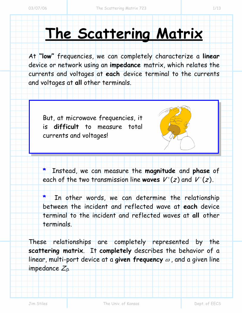
The Scattering Matrix At “low” frequencies, we can completely characterize a linear device or network using an impedance matrix, which relates the currents and voltages at each device terminal to the currents and voltages at all other terminals.
But, at microwave frequencies, it is difficult to measure total currents and voltages!
* Instead, we can measure the magnitude and phase of each of the two transmission line waves ( ) and ( )V z V z+ − . * In other words, we can determine the relationship between the incident and reflected wave at each device terminal to the incident and reflected waves at all other terminals.
These relationships are completely represented by the scattering matrix. It completely describes the behavior of a linear, multi-port device at a given frequency ω , and a given line impedance Z0.
03/07/06 The Scattering Matrix 723 2/13
Jim Stiles The Univ. of Kansas Dept. of EECS
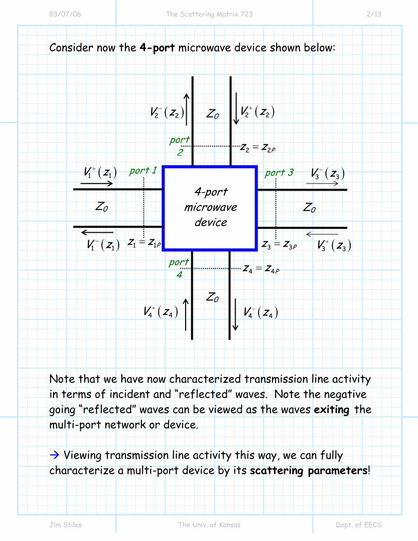
Consider now the 4-port microwave device shown below:
Note that we have now characterized transmission line activity in terms of incident and “reflected” waves. Note the negative going “reflected” waves can be viewed as the waves exiting the multi-port network or device.
Viewing transmission line activity this way, we can fully characterize a multi-port device by its scattering parameters!
( )1 1V z+
( )4 4V z+
( )3 3V z+
( )2 2V z+
port 1
( )1 1V z−
( )4 4V z−
( )3 3V z−
( )2 2V z−
port 3
port 4
port 2
4-port microwave
device Z0 Z0
Z0
Z0
3 3Pz z=
2 2Pz z=
1 1Pz z=
4 4Pz z=
03/07/06 The Scattering Matrix 723 3/13
Jim Stiles The Univ. of Kansas Dept. of EECS
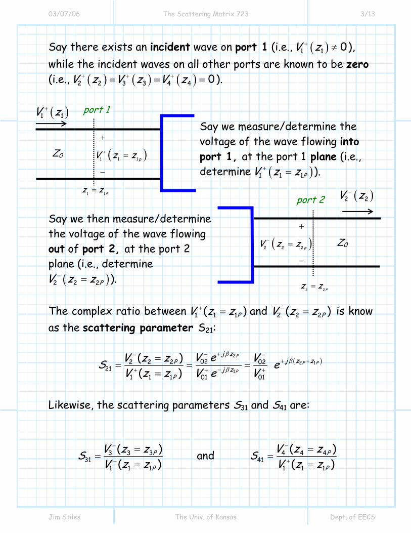
Say there exists an incident wave on port 1 (i.e., ( )1 1 0V z+ ≠ ), while the incident waves on all other ports are known to be zero (i.e., ( ) ( ) ( )2 2 3 3 4 4 0V z V z V z+ + += = = ).
Say we measure/determine the voltage of the wave flowing into port 1, at the port 1 plane (i.e., determine ( )1 1 1PV z z+ = ).
Say we then measure/determine the voltage of the wave flowing out of port 2, at the port 2 plane (i.e., determine
( )2 2 2PV z z− = ). The complex ratio between 1 1 1 2 2 2( ) and ( )P PV z z V z z+ −= = is know as the scattering parameter S21:
( )2
2 1
1
022 2 2 0221
1 1 1 01 01
( )( )
PP P
P
j zj z zP
j zP
V eV z z VS eV z z V e V
ββ
β
+−− −+ +
−+ + +
== = =
=
Likewise, the scattering parameters S31 and S41 are:
3 3 3 4 4 431 41
1 1 1 1 1 1
( )( ) and ( ) ( )
P P
P P
V z zV z zS SV z z V z z
−−
+ +
=== =
= =
( )1 1V z+ port 1
Z0
1 1Pz z=
( )1 1 1 pV z z+
+
=
−
( )2 2V z− port 2
Z0
2 2Pz z=
( )2 2 2pV z z−
+
=
−
03/07/06 The Scattering Matrix 723 4/13
Jim Stiles The Univ. of Kansas Dept. of EECS
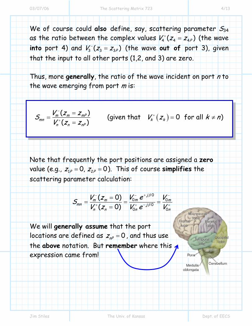
We of course could also define, say, scattering parameter S34 as the ratio between the complex values 4 4 4( )PV z z+ = (the wave into port 4) and 3 3 3( )PV z z− = (the wave out of port 3), given that the input to all other ports (1,2, and 3) are zero. Thus, more generally, the ratio of the wave incident on port n to the wave emerging from port m is:
( )( ) (given that 0 for all )( )
m m mPmn k k
n n nP
V z zS V z k nV z z
−+
+
== = ≠
=
Note that frequently the port positions are assigned a zero value (e.g., 1 20, 0P Pz z= = ). This of course simplifies the scattering parameter calculation:
00 0
000
( 0) ( 0)
jmm m m
mn jn n nn
V eV z VSV z VV e
β
β
+−− −
−+ ++
== = =
=
We will generally assume that the port locations are defined as 0nPz = , and thus use the above notation. But remember where this expression came from!
Microwave lobe
03/07/06 The Scattering Matrix 723 5/13
Jim Stiles The Univ. of Kansas Dept. of EECS
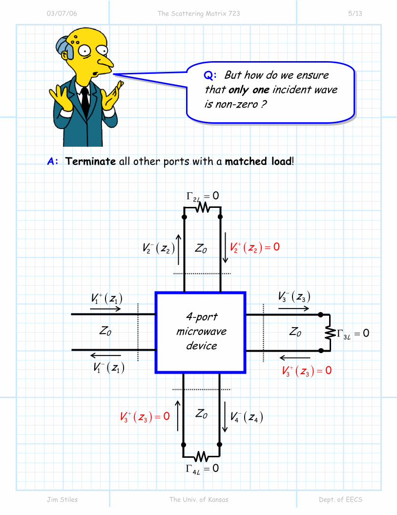
A: Terminate all other ports with a matched load!
( )1 1V z+
( )3 3 0V z+ =
( )3 3 0V z+ =
( )2 2 0V z+ =
( )1 1V z−
( )4 4V z−
( )3 3V z−
( )2 2V z−
4-port microwave
device Z0 Z0
Z0
Z0
4 0LΓ =
3 0LΓ =
2 0LΓ =
Q: But how do we ensure that only one incident wave is non-zero ?

03/07/06 The Scattering Matrix 723 6/13
Jim Stiles The Univ. of Kansas Dept. of EECS
Note that if the ports are terminated in a matched load (i.e., 0LZ Z= ), then 0nLΓ = and therefore:
( ) 0n nV z+ =
In other words, terminating a port ensures that there will be no signal incident on that port!
A: Actually, both statements are correct! You must be careful to understand the physical definitions of the plus and minus directions—in other words, the propagation directions of waves ( )n nV z+ and ( )n nV z− !
Q: Just between you and me, I think you’ve messed this up! In all previous handouts you said that if 0LΓ = , the wave in the minus direction would be zero:
( ) 0 if 0LV z− = Γ = but just now you said that the wave in the positive direction would be zero:
( ) 0 if 0LV z+ = Γ = Of course, there is no way that both statements can be correct!

03/07/06 The Scattering Matrix 723 7/13
Jim Stiles The Univ. of Kansas Dept. of EECS
( ) 0 if 0LV z− = Γ =
For example, we originally analyzed this case: In this original case, the wave incident on the load is ( )V z+ (plus direction), while the reflected wave is ( )V z− (minus direction). Contrast this with the case we are now considering: For this current case, the situation is reversed. The wave incident on the load is now denoted as ( )n nV z− (coming out of port n), while the wave reflected off the load is now denoted as ( )n nV z+ (going into port n ).
As a result, ( ) 0n nV z+ = when 0nLΓ = !
LΓ
( )V z−
( )V z+
Z0
nLΓ
( )n nV z+
( )n nV z−
Z0
port n
N-port Microwave Network

03/07/06 The Scattering Matrix 723 8/13
Jim Stiles The Univ. of Kansas Dept. of EECS
Perhaps we could more generally state that for some load LΓ :
( ) ( )reflected incidentL L LV z z V z z= = Γ =
Now, back to our discussion of S-parameters. We found that if
0nPz = for all ports n, the scattering parameters could be directly written in terms of wave amplitudes 0nV + and 0mV − .
( )0
0
(given that 0 for all )mmn k k
n
VS V z k nV
−+
+= = ≠
Which we can now equivalently state as:
0
0
(given that all ports, except port , are )mmn
n
VS nV
−
+= matched
For each case, you must be able to correctly identify the mathematical statement describing the wave incident on, and reflected from, some passive load. Like most equations in engineering, the variable names can change, but the physics described by the mathematics will not!
03/07/06 The Scattering Matrix 723 9/13
Jim Stiles The Univ. of Kansas Dept. of EECS
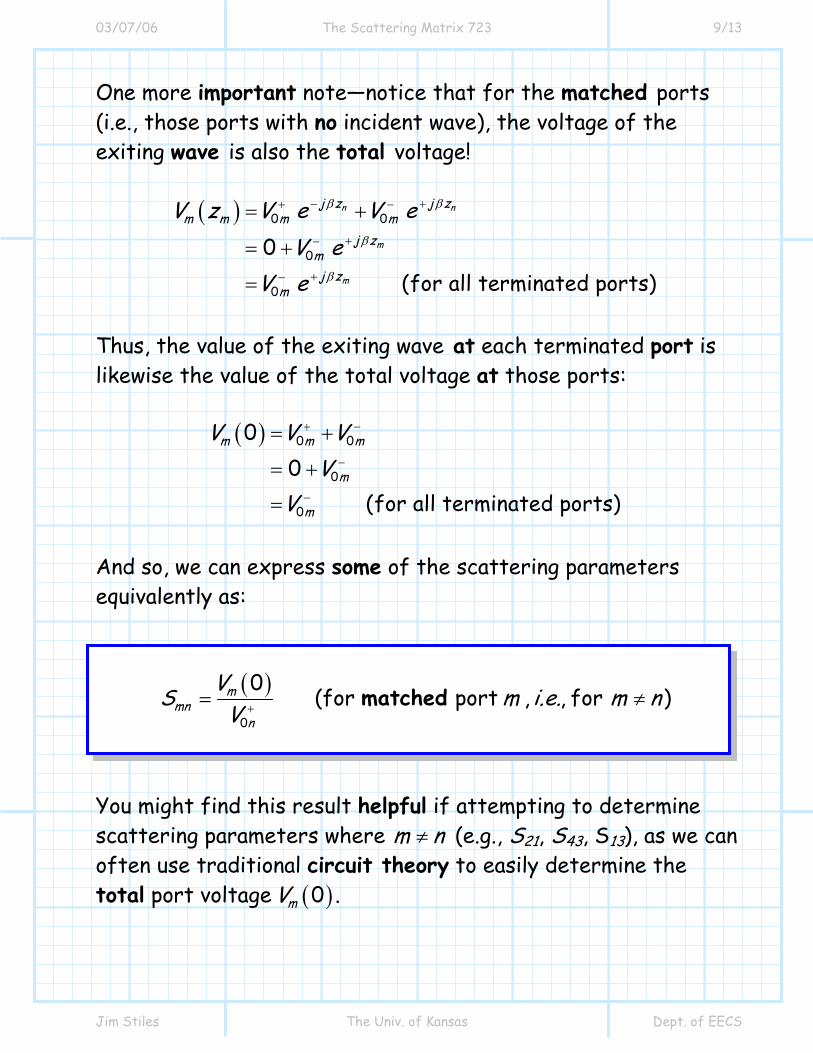
One more important note—notice that for the matched ports (i.e., those ports with no incident wave), the voltage of the exiting wave is also the total voltage!
( ) 0 0
0
0
0(for all terminated ports)
n n
m
m
j z j zm m m m
j zmj z
m
V z V e V eV e
V e
β β
β
β
− ++ −
+−
+−
= +
= +
=
Thus, the value of the exiting wave at each terminated port is likewise the value of the total voltage at those ports:
( ) 0 0
0
0
00
(for all terminated ports)
m m m
m
m
V V VV
V
+ −
−
−
= +
= +
=
And so, we can express some of the scattering parameters equivalently as:
( )0
0 (for port , , for )m
mnn
VS m i.e. m nV += ≠matched
You might find this result helpful if attempting to determine scattering parameters where m n≠ (e.g., S21, S43, S13), as we can often use traditional circuit theory to easily determine the total port voltage ( )0mV .

03/07/06 The Scattering Matrix 723 10/13
Jim Stiles The Univ. of Kansas Dept. of EECS
However, we cannot use the expression above to determine the scattering parameters when m n= (e.g., S11, S22, S33).
Think about this! The scattering parameters for these cases are:
0
0
nnn
n
VSV
−
+=
Therefore, port n is a port where there actually is some incident wave 0nV + (port n is not terminated in a matched load!). And thus, the total voltage is not simply the value of the exiting wave, as both an incident wave and exiting wave exists at port n.
( )4 4 0V z+ =
( )3 3 0V z+ =
( )2 2 0V z+ =
( )1 1V z−
( )4 4V z−
( )3 3V z−
( )2 2V z−
4-port microwave
device Z0 Z0
Z0
Z0
4 0LΓ =
3 0LΓ =
2 0LΓ =
( )1 1 0V z+ ≠
( ) ( ) ( )1 1 10 0 0V V V+ −= + ( ) ( )3 30 0V V −=

03/07/06 The Scattering Matrix 723 11/13
Jim Stiles The Univ. of Kansas Dept. of EECS
Typically, it is much more difficult to determine/measure the scattering parameters of the form Snn , as opposed to scattering parameters of the form Smn (where m n≠ ) where there is only an exiting wave from port m ! We can use the scattering matrix to determine the solution for a more general circuit—one where the ports are not terminated in matched loads! A: Since the device is linear, we can apply superposition. The output at any port due to all the incident waves is simply the coherent sum of the output at that port due to each wave! For example, the output wave at port 3 can be determined by (assuming 0nPz = ):
03 33 03 32 02 31 0134 04V S V S V S V S V− + + + += + + + More generally, the output at port m of an N-port device is:
( )0 01
0N
m mn n nPn
V S V z− +
=
= =∑
Q: I’m not understanding the importance scattering parameters. How are they useful to us microwave engineers?

03/07/06 The Scattering Matrix 723 12/13
Jim Stiles The Univ. of Kansas Dept. of EECS
This expression can be written in matrix form as:
− +=V S V Where −V is the vector:
01 02 03 0T
NV ,V ,V , ,V− − − − −⎡ ⎤= ⎣ ⎦V … and +V is the vector:
01 02 03 0T
NV ,V ,V , ,V+ + + + +⎡ ⎤= ⎣ ⎦V …
Therefore S is the scattering matrix:
11 1
1
n
m mn
S S
S S
⎡ ⎤⎢ ⎥= ⎢ ⎥⎢ ⎥⎣ ⎦
S…
The scattering matrix is a N by N matrix that completely characterizes a linear, N-port device. Effectively, the scattering matrix describes a multi-port device the way that LΓ describes a single-port device (e.g., a load)!

03/07/06 The Scattering Matrix 723 13/13
Jim Stiles The Univ. of Kansas Dept. of EECS
But beware! The values of the scattering matrix for a particular device or network, just like LΓ , are frequency dependent! Thus, it may be more instructive to explicitly write:
( )( ) ( )
( ) ( )
11 1
1
n
m mn
S S
S S
ω ωω
ω ω
⎡ ⎤⎢ ⎥= ⎢ ⎥⎢ ⎥⎣ ⎦
S…
Also realize that—also just like ΓL—the scattering matrix is dependent on both the device/network and the Z0 value of the transmission lines connected to it. Thus, a device connected to transmission lines with
0 50Z = Ω will have a completely different scattering matrix than that same device connected to transmission lines with 0 100Z = Ω !!!

03/07/06 Matched reciprocal lossless 723 1/5
Jim Stiles The Univ. of Kansas Dept. of EECS
Matched, Lossless, Reciprocal Devices
As we discussed earlier, a device can be lossless or reciprocal. In addition, we can likewise classify at being matched. Let’s examine each of these three characteristics, and how they relate to the scattering matrix.
Matched A matched device is another way of saying that the input impedance at each port is equal to Z0 when all other ports are terminated in matched loads. As a result, the reflection coefficient of each port is zero—no signal will be come out of a port if a signal is incident on that port (and only that port). In other words, we want:
0 for all m mm mV S V m− += =
a result that occurs when:
= 0 for all if matchedmmS m
03/07/06 Matched reciprocal lossless 723 2/5
Jim Stiles The Univ. of Kansas Dept. of EECS
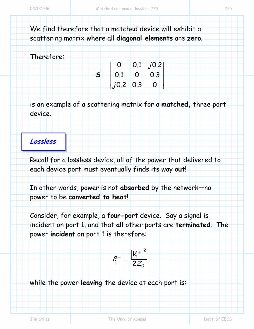
We find therefore that a matched device will exhibit a scattering matrix where all diagonal elements are zero. Therefore:
0 0.1 0.20.1 0 0.30.2 0.3 0
j
j
⎡ ⎤⎢ ⎥⎢ ⎥= ⎢ ⎥⎢ ⎥⎣ ⎦
S
is an example of a scattering matrix for a matched, three port device. Lossless Recall for a lossless device, all of the power that delivered to each device port must eventually finds its way out! In other words, power is not absorbed by the network—no power to be converted to heat! Consider, for example, a four-port device. Say a signal is incident on port 1, and that all other ports are terminated. The power incident on port 1 is therefore:
21
102
VP Z
++ =
while the power leaving the device at each port is:

03/07/06 Matched reciprocal lossless 723 3/5
Jim Stiles The Univ. of Kansas Dept. of EECS
2 21 1 2
1 10 02 2
m mm m
V S VP S PZ Z
− −− += = =
The total power leaving the device is therefore:
( )
1 2 3 4222 2
11 21 31 411 1 1 1222 2
11 21 31 41 1
outP P P P PS P S P S P S PS S S S P
− − − −
+ + + +
+
= + + +
= + + +
= + + +
Note therefore that if the device is lossless, the output power will be equal to the input power, i.e., 1outP P += . This is true only if:
222 211 21 31 41 1S S S S+ + + =
If the device is lossless, this will likewise be true for each of the other ports:
222 2
12 22 32 4222 2 2
13 23 33 432 2 2 2
14 24 34 44
1
1
1
S S S SS S S SS S S S
+ + + =
+ + + =
+ + + =
We can state in general then:
2
11 for all
N
mnm
S n=
=∑
In fact, it can be shown that a lossless device will have a unitary scattering matrix, i.e.:
03/07/06 Matched reciprocal lossless 723 4/5
Jim Stiles The Univ. of Kansas Dept. of EECS
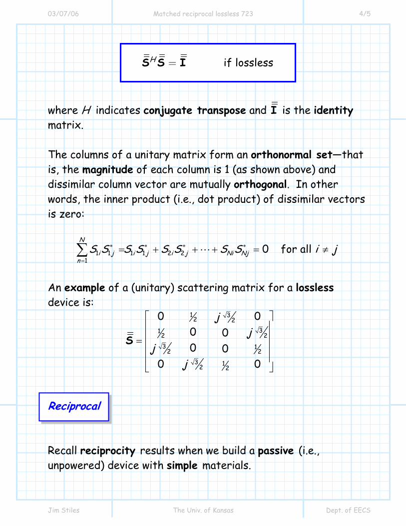
= if losslessHS S I
where H indicates conjugate transpose and I is the identity matrix. The columns of a unitary matrix form an orthonormal set—that is, the magnitude of each column is 1 (as shown above) and dissimilar column vector are mutually orthogonal. In other words, the inner product (i.e., dot product) of dissimilar vectors is zero:
1 1 1 1 2 21
0 for all N
i j i j i j Ni Njn
S S S S S S S S i j∗ ∗ ∗ ∗
=
= + + + = ≠∑
An example of a (unitary) scattering matrix for a lossless device is: Reciprocal Recall reciprocity results when we build a passive (i.e., unpowered) device with simple materials.
1 32 2
312 23 1
2 23 12 2
0 00 00 0
0 0
jj
jj
⎡ ⎤⎢ ⎥⎢ ⎥=⎢ ⎥⎢ ⎥⎣ ⎦
S

03/07/06 Matched reciprocal lossless 723 5/5
Jim Stiles The Univ. of Kansas Dept. of EECS
For a reciprocal network, we find that the elements of the scattering matrix are related as:
mn nmS S= For example, a reciprocal device will have 21 12S S= or
32 23S S= . We can write reciprocity in matrix form as:
= if reciprocalTS S
where T indicates (non-conjugate) transpose. An example of a scattering matrix describing a reciprocal, but lossy and non-matched device is:
0.10 0.20 0.050.400.40 0 0.100.200.20 0.10 0.30 0.120
0.05 0.12 00.10
jjj
j jj
−−⎡ ⎤⎢ ⎥−⎢ ⎥=⎢ ⎥− − −⎢ ⎥−⎣ ⎦
S

3/7/2006 Example A Lossless Reciprocal Network 1/4
Jim Stiles The Univ. of Kansas Dept. of EECS
Example: A Lossless, Reciprocal Network
A lossless, reciprocal 3-port device has S-parameters of
11 1 2S = , 31 1 2S = , and 33 0S = . It is likewise known that all scattering parameters are real.
Find the remaining 6 scattering parameters. A: Yes I have! Note I said the device was lossless and reciprocal!
Start with what we currently know:
12 12 13
21 22 231
322 0
S SS S S
S
⎡ ⎤⎢ ⎥= ⎢ ⎥⎢ ⎥⎣ ⎦
S
Because the device is reciprocal, we then also know:
21 12S S= 113 31 2S S= = 32 23S S=
Q: This problem is clearly impossible—you have not provided us with sufficient information!

3/7/2006 Example A Lossless Reciprocal Network 2/4
Jim Stiles The Univ. of Kansas Dept. of EECS
And therefore:
1 12 21 2
21 22 321
322 0
SS S S
S
⎡ ⎤⎢ ⎥= ⎢ ⎥⎢ ⎥⎣ ⎦
S
Now, since the device is lossless, we know that:
( ) ( )
22 211 21 31
2221 12 21 2
1 S S S
S
= + +
= + +
22 2
12 22 3222 2
21 22 32
1 S S SS S S
= + +
= + +
( ) ( )
2 2 213 23 33
2221 12 32 2
1 S S S
S
= + +
= + +
and:
11 12 21 22 31 32
1 12 21 21 22 322
0 S S S S S SS S S S
∗ ∗ ∗
∗ ∗ ∗
= + +
= + +
( ) ( )11 13 21 23 31 33
1 1 12 21 322 2
00
S S S S S SS S
∗ ∗ ∗
∗
= + +
= + +
( ) ( )12 13 22 23 32 33
121 22 32 322
00
S S S S S SS S S S
∗ ∗ ∗
∗
= + +
= + +
Columns have unit magnitude.
Columns are orthogonal.

3/7/2006 Example A Lossless Reciprocal Network 3/4
Jim Stiles The Univ. of Kansas Dept. of EECS
These six expressions simplify to:
1221S =
22 2
21 22 321 S S S= + +
132 2S =
1 12 21 21 22 3220 S S S S= + +
( )
121 322 20 S S= +
( )1
21 22 3220 S S S= +
where we have used the fact that since the elements are all real, then 21 21S S∗ = (etc.).
Q A: Actually, we have six real equations and six real
unknowns, since scattering element has a magnitude and phase. In this case we know the values are real, and thus
the phase is either 0 or 180 (i.e., 0 1je = or 1je π = − ); however, we do not know which one!
From the first three equations, we can find the magnitudes:
Q: I count the about expressions and find 6 equations yet only a paltry 3 unknowns. Your typical buffoonery appears to have led to an over-constrained condition for which there is no solution!

3/7/2006 Example A Lossless Reciprocal Network 4/4
Jim Stiles The Univ. of Kansas Dept. of EECS
1221S = 1
222S = 132 2S =
and from the last three equations we find the phase:
1221S = 1
222S = 132 2S = −
Thus, the scattering matrix for this lossless, reciprocal device is:
1 1 12 2 2
1 1 12 2 2
1 12 2 0
−
−
⎡ ⎤⎢ ⎥= ⎢ ⎥⎢ ⎥⎣ ⎦
S

3/3/2005 Example Determining the Scattering Matrix.doc 1/5
Jim Stiles The Univ. of Kansas Dept. of EECS
Example: Determining the Scattering Matrix
Let’s determine the scattering matrix of this two-port device: The first step is to terminate port 2 with a matched load, and then determine the values:
( )1 1 1PV z z− = and ( )2 2 2PV z z− = in terms of ( )1 1 1PV z z+ = .
0Z 0Z2Z0
1 0Pz =
z1
2 0Pz =
z2
0Z 2Z0
1 0Pz =
z1
2 0Pz =
Z0 ( )2 2 0V z+
=
−
( )1 1V z+
−
3/3/2005 Example Determining the Scattering Matrix.doc 2/5
Jim Stiles The Univ. of Kansas Dept. of EECS
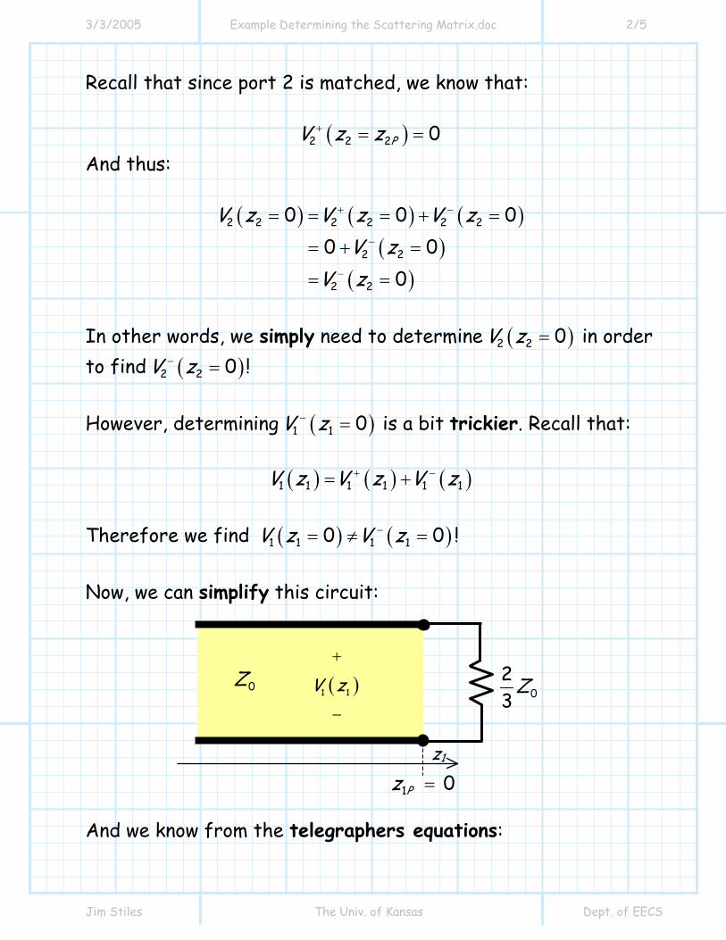
Recall that since port 2 is matched, we know that:
( )2 2 2 0PV z z+ = = And thus:
( ) ( ) ( )( )
( )
2 2 2 2 2 2
2 2
2 2
0 0 00 0
0
V z V z V zV z
V z
+ −
−
−
= = = + =
= + =
= =
In other words, we simply need to determine ( )2 2 0V z = in order to find ( )2 2 0V z− = ! However, determining ( )1 1 0V z− = is a bit trickier. Recall that:
( ) ( ) ( )1 1 1 1 1 1V z V z V z+ −= +
Therefore we find ( ) ( )1 1 1 10 0V z V z−= ≠ = ! Now, we can simplify this circuit:
And we know from the telegraphers equations:
0Z0
23
Z
1 0Pz =
z1
( )1 1V z+
−

3/3/2005 Example Determining the Scattering Matrix.doc 3/5
Jim Stiles The Univ. of Kansas Dept. of EECS
( ) ( ) ( )1 1
1 1 1 1 1 1
01 01j z j z
V z V z V zV e V e
+ −
− β + β+ −
= +
= +
Since the load 02 3Z is located at 1 0z = , we know that the boundary condition leads to:
( ) ( )1 11 1 01
j z j zLV z V e e− β + β+= + Γ
where:
( )( )( )( )
23 0 0
23 0 0
23
23
13
53
11
0 2
LZ ZZ Z
.
−=
+
−=
+−
=
= −
Γ
Therefore:
( ) 11 1 01
j zV z V e − β+ += and ( ) ( ) 11 1 01 0 2 j zV z V . e + β− += −
and thus:
( ) ( )01 1 01 010 jV z V e V− β+ + += = =
( ) ( ) ( )0
1 1 01 010 0 2 0 2jV z V . e . V+ β− + += = − = − We can now determine 11S !
( )( )
1 1 0111
1 1 01
0 0 2 0 20
V z . VS .V z V
− +
+ +
= −= = = −
=

3/3/2005 Example Determining the Scattering Matrix.doc 4/5
Jim Stiles The Univ. of Kansas Dept. of EECS
Now its time to find ( )2 2 0V z− = ! Again, since port 2 is terminated, the incident wave on port 2 must be zero, and thus the value of the exiting wave at port 2 is equal to the total voltage at port 2:
( ) ( )2 2 2 20 0V z V z− = = =
This total voltage is relatively easy to determine. Examining the circuit, it is evident that ( ) ( )1 1 2 20 0V z V z= = = . Therefore:
( ) ( )( ) ( )( )
( )( )
2 2 1 1
0 001
01
01
0 0
0 2
1 0 20 8
j j
V z V z
V e . e
V .V .
− β + β+
+
+
= = =
= −
= −
=
And thus the scattering parameter 21S is:
( )( )
2 2 0121
1 1 01
0 0 8 0 80
V z . VS .V z V
− +
+ +
== = =
=
0Z2Z0
1 0Pz =
z1
2 0Pz =
Z0 ( )2 2 0V z+
=
−
( )1 1 0V z+
−
=

3/3/2005 Example Determining the Scattering Matrix.doc 5/5
Jim Stiles The Univ. of Kansas Dept. of EECS
Now we just need to find 12S and 22S . Q: Yikes! This has been an awful lot of work, and you mean that we are only half-way done!? A: Actually, we are nearly finished! Note that this circuit is symmetric—there is really no difference between port 1 and port 2. If we “flip” the circuit, it remains unchanged! Thus, we can conclude due to this symmetry that:
11 22 0 2S S .= = − and:
21 12 0 8S S .= =
Note this last equation is likewise a result of reciprocity. Thus, the scattering matrix for this two port network is:
0 2 0 80 8 0 2
. .. .
−⎡ ⎤= ⎢ ⎥−⎣ ⎦
S
0Z 0Z2Z0
2 0Pz =
z2
1 0Pz =
z1
3/3/2005 Example The Scattering Matrix.doc 1/6
Jim Stiles The Univ. of Kansas Dept. of EECS
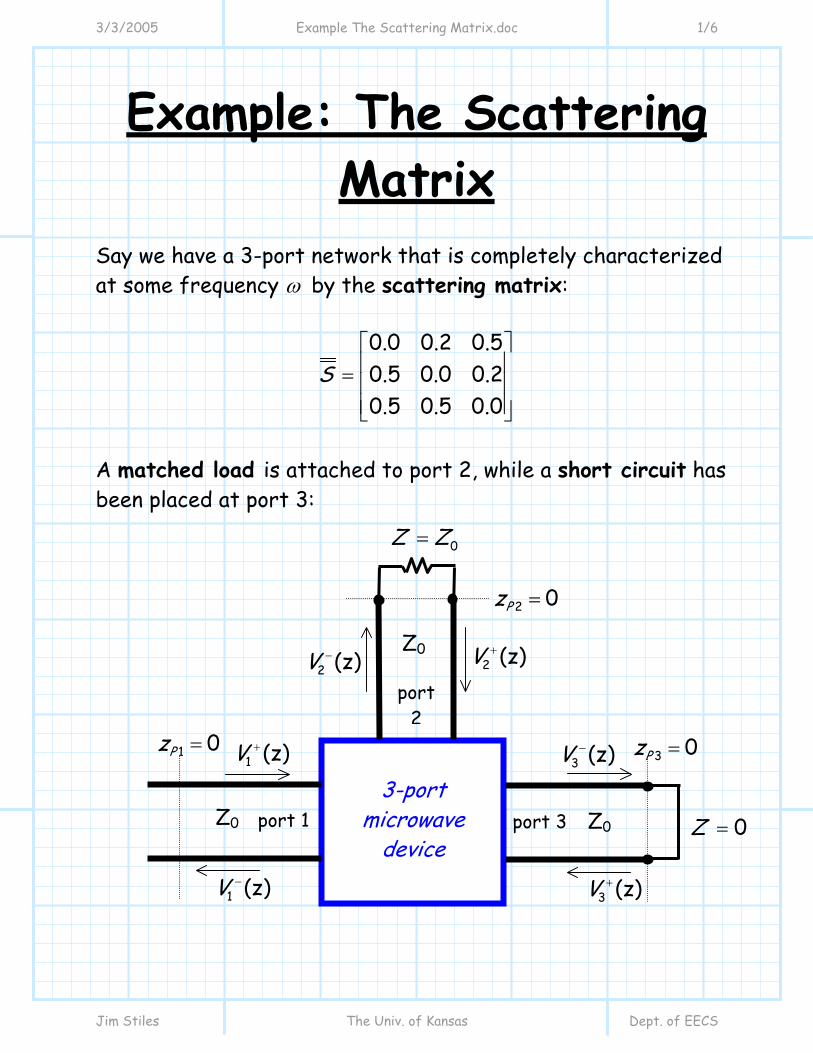
Example: The Scattering Matrix
Say we have a 3-port network that is completely characterized at some frequency ω by the scattering matrix:
0.0 0.2 0.50.5 0.0 0.20.5 0.5 0.0
S⎡ ⎤⎢ ⎥= ⎢ ⎥⎢ ⎥⎣ ⎦
A matched load is attached to port 2, while a short circuit has been placed at port 3:
1 (z)V +
3 (z)V +
2 (z)V +
port 1
1 (z)V −
3 (z)V −
2 (z)V −
port 3
port 2
3-port microwave
device Z0 Z0
Z0
3 0Pz =
2 0Pz =
1 0Pz =
0Z Z=
0Z =

3/3/2005 Example The Scattering Matrix.doc 2/6
Jim Stiles The Univ. of Kansas Dept. of EECS
Because of the matched load at port 2 (i.e., 0LΓ = ), we know that:
022 2
2 2 02
( 0) 0( 0)
VV zV z V
++
− −
== =
=
and therefore:
02 0V + =
NO!! Remember, the signal 2 ( )V z− is incident on the matched load, and 2 ( )V z+ is the reflected wave from the load (i.e., 2 ( )V z+ is incident on port 2). Therefore, 02 0V + = is correct! Likewise, because of the short circuit at port 3 ( 1LΓ = − ):
3 3 03
3 3 03
( 0) 1( 0)
V z VV z V
+ +
− −
== = −
=
and therefore:
03 03V V+ −= −
You’ve made a terrible mistake! Fortunately, I was here to correct it for you—since 0LΓ = , the constant 02V − (not 02V + ) is equal to zero.

3/3/2005 Example The Scattering Matrix.doc 3/6
Jim Stiles The Univ. of Kansas Dept. of EECS
Problem: a) Find the reflection coefficient at port 1, i.e.:
011
01
VV
−
+Γ
b) Find the transmission coefficient from port 1 to port 2, i.e.,
0221
01
VTV
−
+
NO!!! The above statement is not correct!
Remember, 1 1 11V V S− + = only if ports 2 and 3 are terminated in matched loads! In this problem port 3 is terminated with a short circuit.
I am amused by the trivial problems that you apparently find so difficult. I know that:
011 11
01
0.0V SV
−
+Γ = = =
and
0221 21
01
0.5VT SV
−
+= = =
3/3/2005 Example The Scattering Matrix.doc 4/6
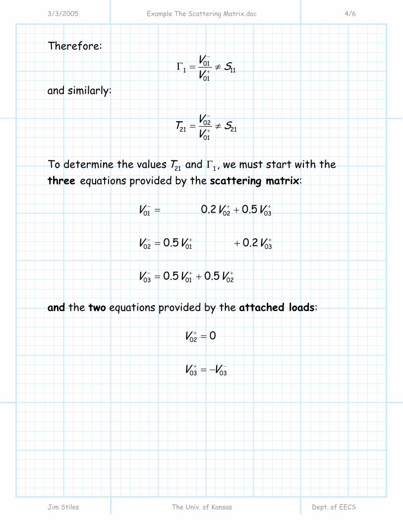
Jim Stiles The Univ. of Kansas Dept. of EECS
Therefore: 01
1 1101
V SV
−
+Γ = ≠
and similarly:
0221 21
01
VT SV
−
+= ≠
To determine the values 21T and 1Γ , we must start with the three equations provided by the scattering matrix:
01 02 03
02 01 03
03 01 02
0 2 0 5
0 5 0 2
0 5 0 5
V . V . V
V . V . V
V . V . V
− + +
− + +
− + +
= +
= +
= +
and the two equations provided by the attached loads:
02
03 03
0V
V V
+
+ −
=
= −

3/3/2005 Example The Scattering Matrix.doc 5/6
Jim Stiles The Univ. of Kansas Dept. of EECS
We can divide all of these equations by 01V + , resulting in:
01 02 031
01 01 01
02 0321
01 01
03 02
01 01
02
01
03 03
01 01
0 2 0 5
0 5 0 2
0 5 0 5
0
V V V. .V V V
V VT . .V V
V V. .V V
VV
V VV V
− + +
+ + +
− +
+ +
− +
+ +
+
+
+ −
+ +
= +
= = +
= +
=
= −
Γ =
Look what we have—5 equations and 5 unknowns! Inserting equations 4 and 5 into equations 1 through 3, we get:
01 031
01 01
02 0321
01 01
03
01
0 5
0 5 0 2
0 5
V V.V V
V VT . .V V
V .V
− +
+ +
− +
+ +
−
+
= −
= = −
=
Γ =

3/3/2005 Example The Scattering Matrix.doc 6/6
Jim Stiles The Univ. of Kansas Dept. of EECS
Solving, we find:
( )
( )
1
21
0 5 0 5 0 25
0 5 0 2 0 5 0 4
. . .
T . . . .
= − = −
= − =
Γ