407-MM-CH29
70
BHT-407-MM-4 29-00-00 16 FEB 2012 Rev. 34 Page 1 ECCN EAR99 TABLE OF CONTENTS Paragraph Chapter/Section Page Number Title Number Number CHAPTER 29 — HYDRAULIC SYSTEM HYDRAULIC SYSTEM 29-1 Hydraulic System — Description ................................................... 29-00-00 5 29-2 Hydraulic System — Operational Check........................................ 29-00-00 9 29-3 Hydraulic System — Flushing ........................................................ 29-00-00 12 29-4 Hydraulic System — Troubleshooting............................................ 29-00-00 13 29-5 Hydraulic System — Leakage Limits ............................................. 29-00-00 21 29-6 Leakage Limits — Scope .......................................................... 29-00-00 21 29-7 Leakage Limits — Causes of Leakage ..................................... 29-00-00 21 29-8 Leakage Limits — Leakage Types ........................................... 29-00-00 21 29-9 Leakage Limits — Leakage Checks ......................................... 29-00-00 21 29-10 Hydraulic System — Air Bleed ....................................................... 29-00-00 22 29-11 Hydraulic System — Functional Test with the Hydraulic Test Stand...................................................................................... 29-00-00 23 29-12 Hydraulic System — Functional Test with the Helicopter Hydraulic Pump.............................................................................. 29-00-00 24 29-13 Hydraulic Pump — Operational Check .......................................... 29-00-00 25 29-14 Hydraulic System Components — Description .............................. 29-00-00 26 29-15 Reservoir Assembly — Description ............................................... 29-00-00 26 29-16 Reservoir Assembly — Removal .............................................. 29-00-00 26 29-17 Reservoir Assembly — Disassembly ........................................ 29-00-00 26 29-18 Reservoir Assembly — Inspection and Repair ......................... 29-00-00 28 29-19 Reservoir Assembly — Assembly............................................. 29-00-00 28 29-20 Reservoir Assembly — Installation ........................................... 29-00-00 29 29-21 Hydraulic System Pump — Description ......................................... 29-00-00 30 29-22 Hydraulic System Pump — Removal ........................................ 29-00-00 30 29-23 Hydraulic System Pump — Disassembly....................................... 29-00-00 30 29-24 Hydraulic System Pump — Inspection ..................................... 29-00-00 32 29-25 Hydraulic pump drive — inspection, Pump Assembly P/N 206-076-030-111 ............................................................... 29-00-00 32 29-26 Hydraulic Pump Drive — Inspection, Pump Assembly P/N 206-076-030-117 ............................................................... 29-00-00 34 29-27 Hydraulic System Pump — Assembly ...................................... 29-00-00 34 29-28 Hydraulic System Pump — Installation..................................... 29-00-00 38 29-29 Filter Assemblies — Description .................................................... 29-00-00 38 29-30 Filter Assemblies — Operational Check ........................................ 29-00-00 40 29-31 Filter Assemblies — Removal ................................................... 29-00-00 40 29-32 Filter Assemblies — Disassembly ............................................ 29-00-00 42 29-33 Filter Assemblies — Inspection ................................................ 29-00-00 42 29-34 Filter Assemblies — Assembly ................................................. 29-00-00 43 29-35 Filter Assemblies — Installation................................................ 29-00-00 43 29-36 Element — Description .................................................................. 29-00-00 44 29-37 Element — Removal ................................................................. 29-00-00 44 29-38 Element — Inspection and Cleaning ........................................ 29-00-00 44 29-39 Element — Installation .............................................................. 29-00-00 45 29-40 Solenoid Valve — Description ....................................................... 29-00-00 46
-
Upload
brucie-bruce -
Category
Documents
-
view
41 -
download
11
description
Bell 407 Maintenance Manual Chapter 29
Transcript of 407-MM-CH29
BHT-407-MM-4
29-00-0016 FEB 2012 Rev. 34 Page 1ECCN EAR99
TABLE OF CONTENTS
Paragraph Chapter/Section Page Number Title Number Number
CHAPTER 29 — HYDRAULIC SYSTEM
HYDRAULIC SYSTEM
29-1 Hydraulic System — Description ................................................... 29-00-00 529-2 Hydraulic System — Operational Check........................................ 29-00-00 929-3 Hydraulic System — Flushing........................................................ 29-00-00 1229-4 Hydraulic System — Troubleshooting............................................ 29-00-00 1329-5 Hydraulic System — Leakage Limits ............................................. 29-00-00 2129-6 Leakage Limits — Scope.......................................................... 29-00-00 2129-7 Leakage Limits — Causes of Leakage ..................................... 29-00-00 2129-8 Leakage Limits — Leakage Types ........................................... 29-00-00 2129-9 Leakage Limits — Leakage Checks ......................................... 29-00-00 2129-10 Hydraulic System — Air Bleed....................................................... 29-00-00 2229-11 Hydraulic System — Functional Test with the Hydraulic
Test Stand...................................................................................... 29-00-00 2329-12 Hydraulic System — Functional Test with the Helicopter
Hydraulic Pump.............................................................................. 29-00-00 2429-13 Hydraulic Pump — Operational Check .......................................... 29-00-00 2529-14 Hydraulic System Components — Description .............................. 29-00-00 2629-15 Reservoir Assembly — Description ............................................... 29-00-00 2629-16 Reservoir Assembly — Removal .............................................. 29-00-00 2629-17 Reservoir Assembly — Disassembly........................................ 29-00-00 2629-18 Reservoir Assembly — Inspection and Repair ......................... 29-00-00 2829-19 Reservoir Assembly — Assembly............................................. 29-00-00 2829-20 Reservoir Assembly — Installation ........................................... 29-00-00 2929-21 Hydraulic System Pump — Description ......................................... 29-00-00 3029-22 Hydraulic System Pump — Removal........................................ 29-00-00 3029-23 Hydraulic System Pump — Disassembly....................................... 29-00-00 3029-24 Hydraulic System Pump — Inspection ..................................... 29-00-00 3229-25 Hydraulic pump drive — inspection, Pump Assembly
P/N 206-076-030-111 ............................................................... 29-00-00 3229-26 Hydraulic Pump Drive — Inspection, Pump Assembly
P/N 206-076-030-117 ............................................................... 29-00-00 3429-27 Hydraulic System Pump — Assembly ...................................... 29-00-00 3429-28 Hydraulic System Pump — Installation..................................... 29-00-00 3829-29 Filter Assemblies — Description .................................................... 29-00-00 3829-30 Filter Assemblies — Operational Check ........................................ 29-00-00 4029-31 Filter Assemblies — Removal................................................... 29-00-00 4029-32 Filter Assemblies — Disassembly ............................................ 29-00-00 4229-33 Filter Assemblies — Inspection ................................................ 29-00-00 4229-34 Filter Assemblies — Assembly ................................................. 29-00-00 4329-35 Filter Assemblies — Installation................................................ 29-00-00 4329-36 Element — Description .................................................................. 29-00-00 4429-37 Element — Removal................................................................. 29-00-00 4429-38 Element — Inspection and Cleaning ........................................ 29-00-00 4429-39 Element — Installation.............................................................. 29-00-00 4529-40 Solenoid Valve — Description ....................................................... 29-00-00 46

BHT-407-MM-4
29-00-00Page 2 Rev. 34 16 FEB 2012 ECCN EAR99
TABLE OF CONTENTS (CONT)
Paragraph Chapter/Section Page Number Title Number Number
29-41 Solenoid Valve — Removal ...................................................... 29-00-00 4629-42 Solenoid Valve — Disassembly................................................ 29-00-00 4629-43 Solenoid Valve — Inspection.................................................... 29-00-00 4629-44 Solenoid Valve — Assembly..................................................... 29-00-00 4829-45 Solenoid Valve — Installation ................................................... 29-00-00 4829-46 Hydraulic Flight Control Relief Valve — Description...................... 29-00-00 4929-47 Hydraulic Flight Control Relief Valve — Removal .................... 29-00-00 4929-48 Hydraulic Flight Control Relief Valve — Inspection .................. 29-00-00 4929-49 Hydraulic Flight Control Relief Valve — Installation ................. 29-00-00 4929-50 Return and Pressure Coupling Halves — Description ................... 29-00-00 5029-51 Return and Pressure Coupling Halves — Removal.................. 29-00-00 5029-52 Return and Pressure Coupling Halves — Inspection ............... 29-00-00 5029-53 Return and Pressure Coupling Halves — Installation............... 29-00-00 5129-54 Hydraulic Pressure Switch — Description ..................................... 29-00-00 5129-55 Hydraulic Pressure Switch — Inspection.................................. 29-00-00 5129-56 Hydraulic System Manifold — Description..................................... 29-00-00 5129-57 Hydraulic System Manifold — Removal ................................... 29-00-00 5129-58 Hydraulic System Manifold — Disassembly ............................. 29-00-00 5329-59 Hydraulic System Manifold — Inspection ................................. 29-00-00 5329-60 Hydraulic System Manifold — Assembly ....................................... 29-00-00 5329-61 Hydraulic System Manifold — Installation ................................ 29-00-00 5429-62 Hydraulic Hoses and Tube Assemblies — Description.................. 29-00-00 5429-63 Hydraulic Hoses and Tube Assemblies — Removal ................ 29-00-00 5429-64 Hydraulic Hoses and Tube Assemblies — Inspection and
Cleaning.................................................................................... 29-00-00 5429-65 Hydraulic Hoses and Tube Assemblies — Installation ............. 29-00-00 5529-66 Servo Actuators — 12-Month Inspection ....................................... 29-00-00 5529-67 Servo Actuators — 24-Month Inspection ....................................... 29-00-00 5729-68 Cyclic and Collective Servo Actuators — Description.................... 29-00-00 6129-69 Cyclic and Collective Servo Actuators — Removal .................. 29-00-00 6529-70 Cyclic and Collective Servo Actuators — Inspection and
Cleaning.................................................................................... 29-00-00 6529-71 Cyclic and Collective Servo Actuators — Installation ............... 29-00-00 6629-72 Directional Control Servo Actuator — Description ....................... 29-00-00 6729-73 Directional Control Servo Actuator — Removal ...................... 29-00-00 6929-74 Directional Control Servo Actuator — Installation ................... 29-00-00 69
FIGURES
Figure Page Number Title Number
29-1 Hydraulic System — Description ........................................................................ 629-2 Hydraulic System — Schematic.......................................................................... 2029-3 Hydraulic System Manifold — Maintenance Practices ....................................... 2729-4 Hydraulic System Pump — Maintenance Practices............................................ 31

BHT-407-MM-4
29-00-00ECCN EAR99
FIGURES (CONT)
Figure Page Number Title Number
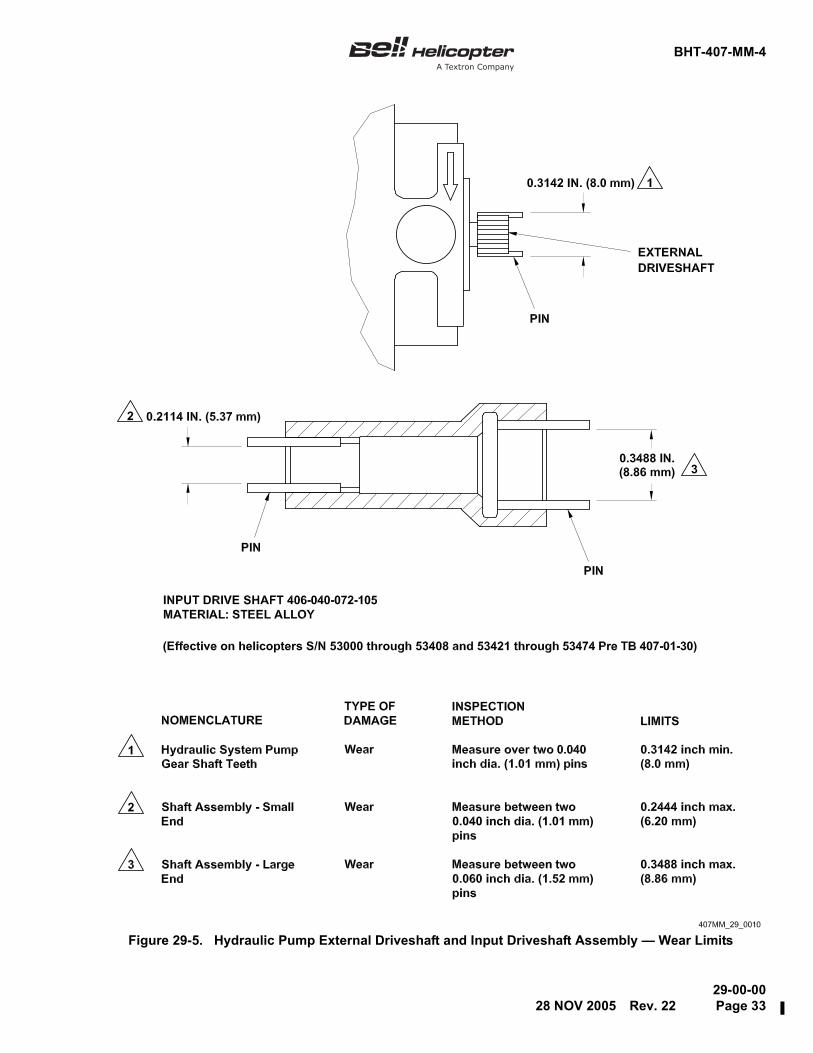
29-5 Hydraulic Pump External Driveshaft and Input Driveshaft Assembly —Wear Limits ......................................................................................................... 33
29-6 Hydraulic Input Shaft — Installation.................................................................... 3529-7 Interconnect Adapter — Inspection..................................................................... 3629-8 Input Shaft — Inspection..................................................................................... 3729-9 Filter Assembly and Element — Maintenance Practices .................................... 3929-10 Workaid No. 1 — Dummy Filter Element ............................................................ 4129-11 Solenoid and Relief Valves ................................................................................. 4729-12 Hydraulic System Manifold — Maintenance Practices ....................................... 5229-13 Servo Actuators — 12-Month Inspection ............................................................ 5629-14 Servo Actuators — 24-Month Inspection ............................................................ 5829-15 Cyclic and Collective Servo Actuators and Bellcranks — Maintenance
Practices ............................................................................................................. 6229-16 Servo Actuator — Schematic.............................................................................. 6429-17 Directional Control Servo Actuator...................................................................... 68
TABLES
Table Page Number Title Number
29-1 Hydraulic System — Trouble 1 ........................................................................... 1429-2 Hydraulic System — Trouble 2 ........................................................................... 1429-3 Hydraulic System — Trouble 3 ........................................................................... 1529-4 Hydraulic System — Trouble 4 ........................................................................... 1629-5 Hydraulic System — Trouble 5 ........................................................................... 1629-6 Hydraulic System — Trouble 6 ........................................................................... 1629-7 Hydraulic System — Trouble 7 ........................................................................... 1729-8 Hydraulic System — Trouble 8 ........................................................................... 1729-9 Hydraulic System — Trouble 9 ........................................................................... 1829-10 Hydraulic System — Trouble 10 ......................................................................... 1929-11 Hydraulic Components — Leakage Limits.......................................................... 22
16 FEB 2012 Rev. 34 Page 3/4


BHT-407-MM-4
29-00-0028 NOV 2005 Rev. 22 Page 5
HYDRAULIC SYSTEM
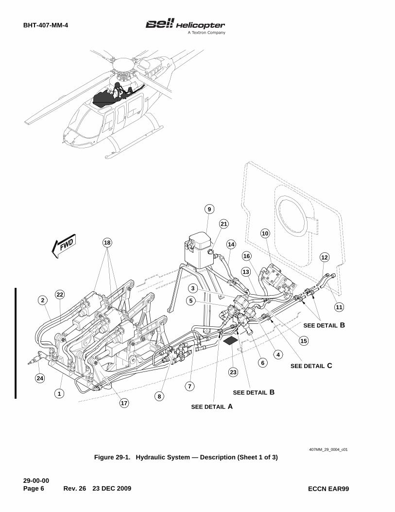
29-1. HYDRAULIC SYSTEM —DESCRIPTION
The helicopter hydraulic system decreases the forcerequired to operate the flight controls. The pressurizedhydraulic fluid and the hydraulic jacks (servoactuators) move the linkages that control the flightattitude and direction. The force that the pilot puts onthe collective, cyclic or the directional controls movesonly the applicable servo valve. This force is muchless than what is required to operate the controlsdirectly. This "hydraulic boost" operates on all thecontrols: the cyclic control stick (forward, aft, andlateral), the collective control stick and the directionalcontrol pedals. There is one collective, one directionaland two cyclic servo actuators.
If a full electrical power failure occurs, the hydraulicsystem is always on. If an hydraulic power failureoccurs, the pilot can operate the controls directly. This"boost off" condition makes sure that the helicopter isalways in the pilot control. During the "boost off"condition, a pressure switch on the hydraulic manifoldmakes the HYDRAULIC SYSTEM annunciator on thecaution/warning/advisory panel come on. The pilot hasa visual indication of the pressure failure.
To turn the hydraulic system off, electrical power mustbe supplied to the solenoid valve. The HYD SYSswitch controls the hydraulic solenoid valve. When thehydraulic system solenoid valve is not energized (theHYD SYS switch is in the ON position or there is anelectrical failure), the pressurized hydraulic fluid flowsto the four servo actuators. When the hydraulic systemsolenoid valve is energized (the HYD SYS switch is inthe OFF position), the pressurized hydraulic fluid flowsto the reservoir and not through the servo actuators(Figure 29-1, Figure 29-3 and Chapter 98 for thehydraulic system wiring diagram).
The helicopter hydraulic system uses hydraulic fluid(Chapter 12). The system is filled at the reservoirassembly. To help prevent contamination when thehydraulic system is serviced, the reservoir assemblyhas a screen below the cover. A sight gauge isinstalled on the left side of the reservoir that will showif the reservoir needs to be serviced (Chapter 12). Youcan find service data on the decals that are on thereservoir assembly and the maintenance platform that
is forward of the hydraulic filters. The caught air is bledout of the system automatically, but if you want tobleed the air yourself, a procedure is given in thischapter. The hydraulic system components include:
• the reservoir assembly (9, Figure 29-1)
• the hydraulic pump (10)
• the return line filter assembly (5)
• the pressure line filter assembly (6)
• the solenoid valve (8)
• the relief valve (7)
• the return coupling half (3)
• the pressure coupling half (4)
• the hydraulic system manifold (1)
• the hydraulic hose and tube assemblies
• the servo actuators (cyclic and collective) (18)and the actuator support (17)
• the servo actuator (directional) (19) and theactuator support (20)
The reservoir assembly (9) supplies hydraulic fluid tothe transmission operated hydraulic pump (10). Thehydraulic pump pressurizes the hydraulic fluid to 1000PSI (-25/+50 PSI) (6895 kPa (-172/+344 kPa)) andsends it to the smaller pressure coupling half (4).
The hydraulic fluid passes through the pressurecoupling half (4) and flows to the pressure line filterassembly (6). The coupling halves are installed tomake maintenance tasks and the tests easier. You canconnect the hydraulic test stand on the couplinghalves, there is one on the pressure line and one onthe return line.
The pressure line filter assembly (6) removesdangerous particles (particles larger than 15 microns).The fluid continues to flow to the relief valve (7).
BHT-407-MM-4
29-00-00Page 6 Rev. 26 23 DEC 2009 ECCN EAR99
Figure 29-1. Hydraulic System — Description (Sheet 1 of 3)NO OBJECT BEYOND THIS POINT 407MM_29_0004_c01
24
1
178
7
23
6
4
15
11
12
10
14
21
9
18
222
16
SEE DETAIL A
SEE DETAIL B
SEE DETAIL C
SEE DETAIL B
13
3
5
BHT-407-MM-4
29-00-0023 DEC 2009 Rev. 26 Page 7ECCN EAR99
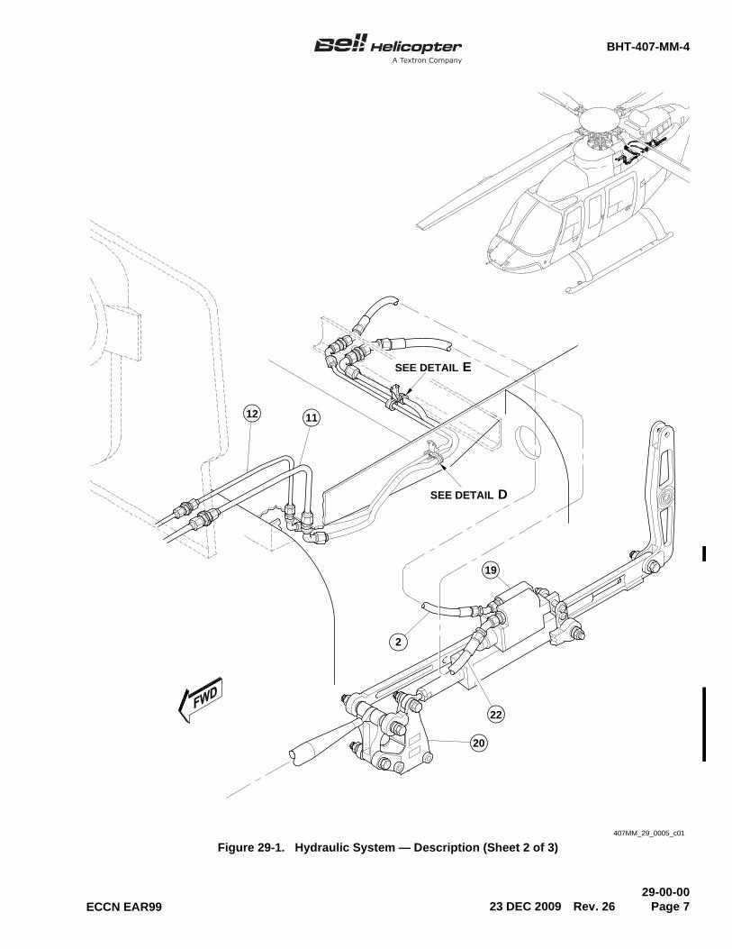
Figure 29-1. Hydraulic System — Description (Sheet 2 of 3)407MM_29_0005_c01
SEE DETAIL D
12
SEE DETAIL E
11
2
20
22
19
BHT-407-MM-4
29-00-00Page 8 Rev. 22 28 NOV 2005
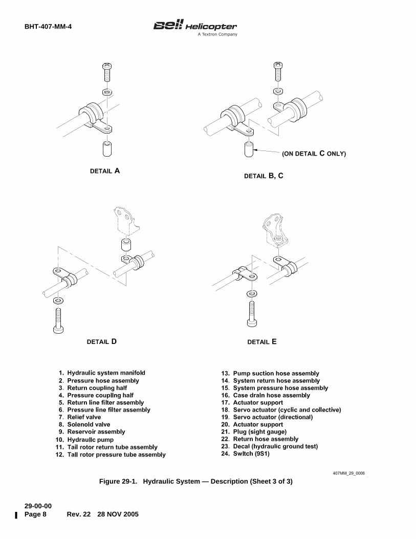
Figure 29-1. Hydraulic System — Description (Sheet 3 of 3)
BHT-407-MM-4
29-00-0028 NOV 2005 Rev. 22 Page 9
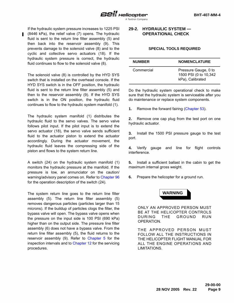
If the hydraulic system pressure increases to 1225 PSI(8446 kPa), the relief valve (7) opens. The hydraulicfluid is sent to the return line filter assembly (5) andthen back into the reservoir assembly (9). Thisprevents damage to the solenoid valve (8) and to thecyclic and collective servo actuators (18). If thehydraulic system pressure is correct, the hydraulicfluid continues to flow to the solenoid valve (8).
The solenoid valve (8) is controlled by the HYD SYSswitch that is installed on the overhead console. If theHYD SYS switch is in the OFF position, the hydraulicfluid is sent to the return line filter assembly (5) andthen to the reservoir assembly (9). If the HYD SYSswitch is in the ON position, the hydraulic fluidcontinues to flow to the hydraulic system manifold (1).
The hydraulic system manifold (1) distributes thehydraulic fluid to the servo valves. The servo valvefollows pilot input. If the pilot input is to extend theservo actuator (18), the servo valve sends sufficientfluid to the actuator piston to extend the actuatoraccordingly. During the actuator movement, thehydraulic fluid leaves the compressing side of thepiston and flows to the system return line.
A switch (24) on the hydraulic system manifold (1)monitors the hydraulic pressure at the manifold. If thepressure is low, an annunciator on the caution/warning/advisory panel comes on. Refer to Chapter 96for the operation description of the switch (24).
The system return line goes to the return line filterassembly (5). The return line filter assembly (5)removes dangerous particles (particles larger than 15microns). If the buildup of particles clogs the filter, thebypass valve will open. The bypass valve opens whenthe pressure on the input side is 100 PSI (690 kPa)higher than on the output side. The pressure line filterassembly (6) does not have a bypass valve. From thereturn line filter assembly (5), the fluid returns to thereservoir assembly (9). Refer to Chapter 5 for theinspection intervals and to Chapter 12 for the servicingprocedures.
29-2. HYDRAULIC SYSTEM —OPERATIONAL CHECK
Do the hydraulic system operational check to makesure that the hydraulic system is serviceable after youdo maintenance or replace system components.
1. Remove the forward fairing (Chapter 53).
2. Remove one cap plug from the test port on onehydraulic actuator.
3. Install the 1500 PSI pressure gauge to the testport.
4. Verify gauge and line for flight controlsinterference.
5. Install a sufficient ballast in the cabin to get themaximum internal gross weight.
6. Prepare the helicopter for a ground run.
WARNING
ONLY AN APPROVED PERSON MUSTBE AT THE HELICOPTER CONTROLSDURING THE GROUND RUNOPERATION.
THE APPROVED PERSON MUSTFOLLOW ALL THE INSTRUCTIONS INTHE HELICOPTER FLIGHT MANUAL FORALL THE ENGINE OPERATIONS ANDLIMITATIONS.
SPECIAL TOOLS REQUIRED
NUMBER NOMENCLATURE
Commercial Pressure Gauge, 0 to 1500 PSI (0 to 10,342 kPa), Calibrated
BHT-407-MM-4
29-00-00Page 10 Rev. 32 29 AUG 2011 ECCN EAR99
NOTE
If you find a leak during the ground run,shut down the engine. Repair the leakbefore you continue this procedure.
7. Start the helicopter. Let the engine become stablefor a period of 5 minutes at idle (BHT-407-FM-1 orBHT-407-FM-2).
8. When the engine oil pressure and thetransmission temperature are in the necessary limits,increase the throttle to the FLY position (100% NR).
CAUTION
WHEN YOU OPERATE THEHELICOPTER CONTROLS WITH THEENGINE IN OPERATION, KEEP YOURCONTROL MOVEMENT TO A MINIMUM.THIS PREVENTS UNCONTROLLEDINPUTS.
9. Slowly operate the cyclic control stick, collectivecontrol stick and the directional control pedals to bleedthe hydraulic system.
10. Operate the helicopter at 100% NR for 5 moreminutes.
11. Decrease the engine speed and set the throttle tothe idle position. Let the engine become stable.
12. Do a cool down of the engine and shut down theengine (BHT-407-FM-1 or BHT-407-FM-2).
13. Examine the hydraulic system lines andcomponents for signs of oil leaks.
14. Start the helicopter. Let the engine become stablefor a period of 5 minutes at idle (BHT-407-FM-1 orBHT-407-FM-2).
15. Make sure that the cyclic control stick is centeredand the collective control stick is in the fully downposition.
16. Set the HYD SYS switch to the ON position.
RESULT:
• The system operates, the cyclic control stickstays in the center and the collective controlstick stays fully down.
• The HYDRAULIC SYSTEM annunciator goesoff.
CORRECTIVE ACTION:
• If hydraulic system does not operate when theswitch is set to the ON position, refer toTable 29-1.
• If the HYDRAULIC SYSTEM annunciatordoes not go off, refer to Chapter 96.
17. Set the HYD SYS switch to the OFF position.
RESULT:
• The system does not operate.
• The HYDRAULIC SYSTEM annunciatorcomes on.
CORRECTIVE ACTION:
• If the system continues to operate when theswitch is set to the OFF position, refer toTable 29-2.
• If the HYDRAULIC SYSTEM annunciatordoes not come on when the switch is set tothe OFF position, refer to Chapter 96.
18. Set the HYD SYS switch to the ON position.
19. Move the cyclic control stick about 1 inch(25.4 mm) forward and aft and then left and right.
RESULT:
• The cyclic control stick operates smoothly andgives equal resistance through the range oftravel.
CORRECTIVE ACTION:
• If the cyclic control stick does not operatesmoothly, refer to Table 29-3.

BHT-407-MM-4
29-00-0029 AUG 2011 Rev. 32 Page 11ECCN EAR99
• If the cyclic control stick has an unequalresistance, refer to Table 29-4.
20. Lift the collective control stick about 1 to 2 inches(25.4 to 50.8 mm) and then put the collective controlstick to the full down position. Do this step two or threetimes.
RESULT:
• The collective control stick operates smoothlyand gives equal resistance through the rangeof travel.
CORRECTIVE ACTION:
• If the collective control stick does not operatesmoothly, refer to Table 29-3.
• If the collective control stick has unequalresistance through the range of travel, refer toTable 29-4.
21. Lightly push the directional control pedals, first tothe right then to the left (approximately 1/2 to 1 inch(12.7 to 25.4 mm)). Do this sequence two or threetimes.
RESULT:
• The directional control pedals operatesmoothly and give equal resistance throughtheir range of travel.
CORRECTIVE ACTION:
• If the directional control pedals motor orcreep, refer to Table 29-5.
22. Increase the throttle to the FLY position(100% NR). Make sure that the hydraulic pressuregauge reads 1000 PSI (-25/+50 PSI) (6895 kPa (-172/+344 kPa)). Examine the hydraulic system for dynamicleaks.
RESULT:
• The hydraulic system oil leaks or dynamicleaks are less than the limits of Table 29-11.
CORRECTIVE ACTION:
• If the hydraulic system has dynamic leaks thatare not in the limits, refer to Table 29-11 orTable 29-6.
23. Decrease the engine speed by setting the throttleto the idle position.
24. Monitor the oil pressure on the gauge on thehydraulic actuator test port.
RESULT:
• The oil pressure indication stays in theoperating limits (BHT-407-FM-1 orBHT-407-FM-2).
CORRECTIVE ACTION:
• If the oil pressure indication is out of theoperation limits, refer to Table 29-9.
25. Monitor the oil pressure on the gauge.
RESULT:
• The oil pressure indication stays stable.
CORRECTIVE ACTION:
• If the oil pressure indication goes up and downwith no flight control input, refer toTable 29-10.
26. Do a cool down of the engine and shut the enginedown (BHT-407-FM-1 or BHT-407-FM-2).
RESULT:
• The oil leaks or static leaks are in the limits ofTable 29-11.
CORRECTIVE ACTION:
• If the hydraulic system has static leaks thatare out of the limits, refer to Table 29-11.
27. On the return oil filter, examine the impendingbypass indicator button.

BHT-407-MM-4
29-00-00Page 12 Rev. 22 28 NOV 2005
RESULT:
• The impending bypass indicator button stayspushed in.
CORRECTIVE ACTION:
• If the impending bypass indicator button is inthe extended position, refer to Table 29-7.
28. Examine the condition of the hydraulic oil.
RESULT:
• The hydraulic oil is clean and clear.
CORRECTIVE ACTION:
• If the hydraulic oil is discolored or smells, referto Table 29-8.
• If the hydraulic oil is contaminated, refer toTable 29-8.
29-3. HYDRAULIC SYSTEM — FLUSHING
NOTE
Water contamination in hydraulic fluidshows by higher opacity and oildiscoloration. The contamination sources
have to be repaired prior to flushing thesystem.
WARNING
PROPER PROTECTIVE EQUIPMENTSHALL BE USED TO PREVENTPERSONNEL INJURIES.
When contaminated, flush the entire system to ensureremoval of all foreign matter as follows:
1. Remove the following parts of the hydraulicsystem and clean in drycleaning solvent (C-304):
• pump (10, Figure 29-1), reservoir (9)
• pump pressure hose (15)
• return hose (14)
• case drain hose (16)
2. Cap or plug all openings.
3. Remove both filter elements and reinstall filterbowls.
4. Inspect filters for solid contaminant anddeformation due to restriction.
5. Connect ground test stand pressure line to thequick disconnect at filter (4).
6. Connect a hose to the return quick disconnect (3)of sufficient length to reach an overboard closedcontainer for contaminated fluid.
NO SOLID CONTAMINANT FOUND
7. Start test stand and adjust to 600 PSI (4137 kPa).
8. Slowly cycle the collective stick full up to fulldown, until the fluid coming from the overboard line isclear.
a. Repeat the process for cyclic left and right.
b. Repeat the process for cyclic fore and aft.
SPECIAL TOOLS REQUIRED
NUMBER NOMENCLATURE
Commercial Hydraulic test stand 1500 PSI (10,342 Kpa)Pressure maximum, 3.0 Gallons per minute.(11.4 L/min.), 10 micron Filter
Refer to BHT-ALL-SPM for specifications.
MATERIALS REQUIRED
NUMBER NOMENCLATURE
C-304 Drycleaning Solvent
BHT-407-MM-4
29-00-0028 NOV 2005 Rev. 22 Page 13
c. Repeat for the directional control.
9. Reinstall serviceable filters, pump and reservoirand lines. (Refer to applicable paragraphs in thissection).
10. Service hydraulic reservoir as per Chapter 12.
11. Air bleed the hydraulic system as per paragraph29-10 and functional test as per paragraph 29-11 orparagraph 29-12.
WITH SOLID CONTAMINANT FOUND
12. Remove all hydraulic actuators (4) and sendthem to an approved facility for tear down inspectionand decontamination.
13. Join the actuators pressure lines to the returnlines with fittings AN919-6.
CAUTION
THE HYDRAULIC ACTUATORS AREBYPASSED, THE HYDRAULIC SYSTEMHAS A VERY LOW RESISTANCE. FLUSHAT VERY LOW PRESSURE TO PREVENTHYDRAULIC FLUID SPILLAGE AND/ORPERSONNEL INJURIES.
14. Set hydraulic test stand to 0 PSI (0 kPa) prior tostart. Slowly increase pressure to 5 PSI (34 kPa).Flush until all solid contaminants are out of the system.
15. Reinstall serviceable components, hydraulicpump, hydraulic actuators, lines, filters, and reservoirs.(Refer to applicable paragraphs in this section).
16. Service the hydraulic system as per Chapter 12.
17. Air bleed the hydraulic system as per paragraph29-10.
18. Functional test hydraulic system as perparagraph 29-11 or paragraph 29-12.
29-4. HYDRAULIC SYSTEM —TROUBLESHOOTING
The troubleshooting tables are included to help inhydraulic system troubleshooting. They show theindication of trouble, probable cause and correctiveaction. Use the troubleshooting tables with thehydraulic system schematic (Figure 29-2), electricalwiring diagrams, operational checks and functionaltests. More procedures are included in this chapterand in other chapters of the maintenance manual.
SPECIAL TOOLS REQUIRED
NUMBER NOMENCLATURE
Commercial Pressure Gauge, 0 to 1500 PSI (0 to 10,342 kPa), Calibrated
Refer to BHT-ALL-SPM for specifications.
MATERIALS REQUIRED
NUMBER NOMENCLATURE
C-107 Hydraulic Fluid Preservative
C-304 Drycleaning Solvent
BHT-407-MM-4
29-00-00Page 14 Rev. 22 28 NOV 2005
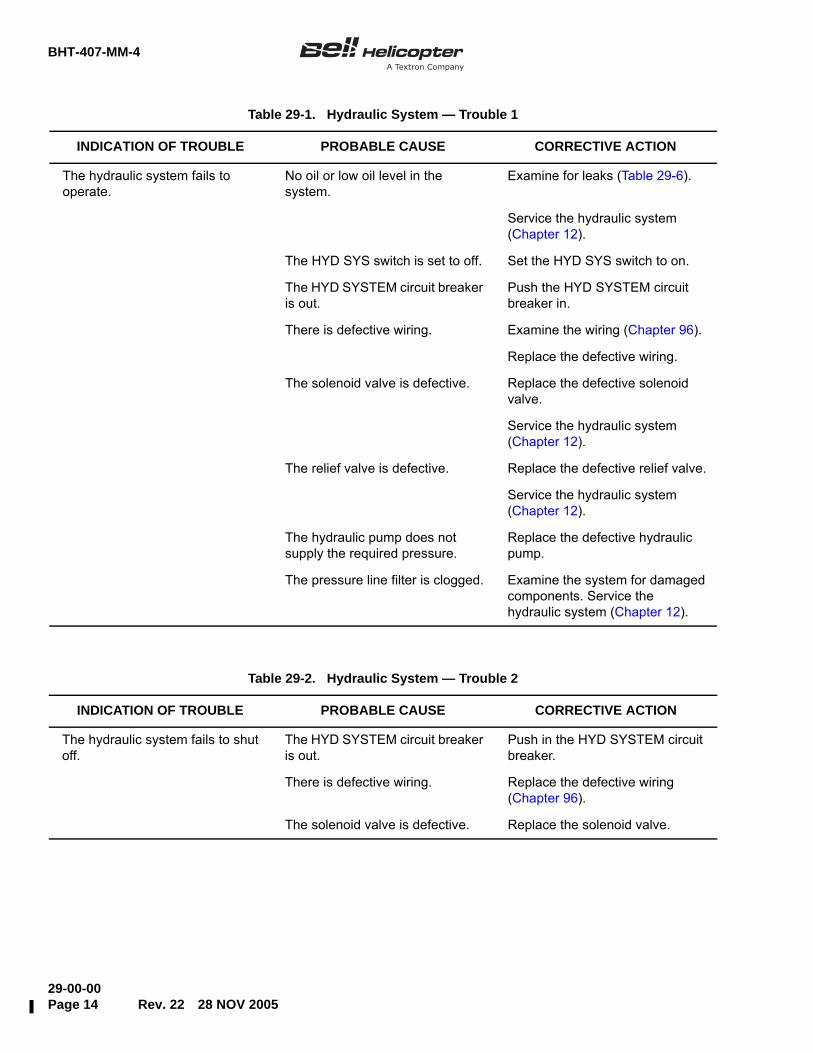
Table 29-1. Hydraulic System — Trouble 1
INDICATION OF TROUBLE PROBABLE CAUSE CORRECTIVE ACTION
The hydraulic system fails to operate.
No oil or low oil level in the system.
Examine for leaks (Table 29-6).
Service the hydraulic system (Chapter 12).
The HYD SYS switch is set to off. Set the HYD SYS switch to on.
The HYD SYSTEM circuit breaker is out.
Push the HYD SYSTEM circuit breaker in.
There is defective wiring. Examine the wiring (Chapter 96).
Replace the defective wiring.
The solenoid valve is defective. Replace the defective solenoid valve.
Service the hydraulic system (Chapter 12).
The relief valve is defective. Replace the defective relief valve.
Service the hydraulic system (Chapter 12).
The hydraulic pump does not supply the required pressure.
Replace the defective hydraulic pump.
The pressure line filter is clogged. Examine the system for damaged components. Service the hydraulic system (Chapter 12).
Table 29-2. Hydraulic System — Trouble 2
INDICATION OF TROUBLE PROBABLE CAUSE CORRECTIVE ACTION
The hydraulic system fails to shut off.
The HYD SYSTEM circuit breaker is out.
Push in the HYD SYSTEM circuit breaker.
There is defective wiring. Replace the defective wiring (Chapter 96).
The solenoid valve is defective. Replace the solenoid valve.

BHT-407-MM-4
29-00-0028 NOV 2005 Rev. 22 Page 15
Table 29-3. Hydraulic System — Trouble 3
INDICATION OF TROUBLE PROBABLE CAUSE CORRECTIVE ACTION
The flight controls do not operate smoothly.
There is air in the hydraulic system.
Examine the hydraulic system for leaks (Table 29-6).
Bleed the hydraulic system (paragraph 29-10).
There is a defective bearing or bushing in the flight controls.
Examine the flight controls (Chapter 67).
Replace the defective bearing or bushing.
There is interference of the components or there is a foreign object.
Examine the flight controls (Chapter 67).
Remove the foreign object.
Replace the damaged, distorted or worn components.
The adjustment or shimming of control linkage connections is not correct.
Examine the flight controls (Chapter 67).
Adjust or shim the control linkage connections.
The servo actuator is not correctly aligned (side loaded).
Adjust the actuator shimming for the actuator support.
There are damaged seals in the servo actuator.
Replace the servo actuator (Chapter 67).
The servo actuator pilot valve friction is too high.
Make sure that the valve friction is less that the limits (Chapter 67).
Replace the servo actuator.
The servo actuator pilot bolt is sticking in the input valve lever.
Remove, clean and install the pilot bolt (Chapter 67).
The servo actuator rod is dirty. Clean servo actuator rod with drycleaning solvent (C-304).
Apply a light coat of hydraulic fluid preservative (C-107) on the servo actuator rod.

BHT-407-MM-4
29-00-00Page 16 Rev. 22 28 NOV 2005
Table 29-4. Hydraulic System — Trouble 4
INDICATION OF TROUBLE PROBABLE CAUSE CORRECTIVE ACTION
The flight controls are rigid. The minimum friction is set too tight.
Adjust the minimum friction (Chapter 67).
The system hydraulic pressure is too low.
Examine (Table 29-9).
The hydraulic filter is clogged. Examine (Table 29-7).
Table 29-5. Hydraulic System — Trouble 5
INDICATION OF TROUBLE PROBABLE CAUSE CORRECTIVE ACTION
There is motor in the directional controls.
The servo valve friction is too high.
Replace the servo actuator.
The friction is too high on the rod end bearing of the control rod.
Replace the control rod.
Table 29-6. Hydraulic System — Trouble 6
INDICATION OF TROUBLE PROBABLE CAUSE CORRECTIVE ACTION
The hydraulic oil leaks are more than the limits of Table 29-11.
There are loose connector fittings or cracks in the flare of the line below the nut.
Tighten the loose fittings or replace the cracked components.
Service the hydraulic system (Chapter 12).
Bleed the hydraulic system (paragraph 29-10).
The preformed packings are damaged.
Replace the damaged packings.
The servo actuator leaks. Replace the servo actuator.
Bleed the hydraulic system (paragraph 29-10).
The hoses or lines are damaged. Replace the damaged hoses or lines.
Bleed the hydraulic system (paragraph 29-10).

BHT-407-MM-4
29-00-0028 NOV 2005 Rev. 22 Page 17
The reservoir cap seal leaks. The reservoir vent is blocked. Remove any obstruction.
The seal is damaged. Remove and replace seal.
Table 29-6. Hydraulic System — Trouble 6 (Cont)
INDICATION OF TROUBLE PROBABLE CAUSE CORRECTIVE ACTION
Table 29-7. Hydraulic System — Trouble 7
INDICATION OF TROUBLE PROBABLE CAUSE CORRECTIVE ACTION
The red button on the differential pressure indicator is in the extended position. (Pressure line filter and/or return line filter).
The filter element is blocked. Clean and examine the filter element.
Set the red button and do an operational check (paragraph 29-2).
Bleed the hydraulic system (paragraph 29-10).
The differential pressure indicator is damaged.
Perform filter assembly operational check (paragraph 29-30).
Replace the filter housing assembly.
Bleed the hydraulic system (paragraph 29-10).
Table 29-8. Hydraulic System — Trouble 8
INDICATION OF TROUBLE PROBABLE CAUSE CORRECTIVE ACTION
The hydraulic oil is contaminated. Water contamination Flush hydraulic system (paragraph 29-3).Verify cap seal condition.
Debris contamination Flush hydraulic system(paragraph 29-3). Replace defective component.
BHT-407-MM-4
29-00-00Page 18 Rev. 22 28 NOV 2005
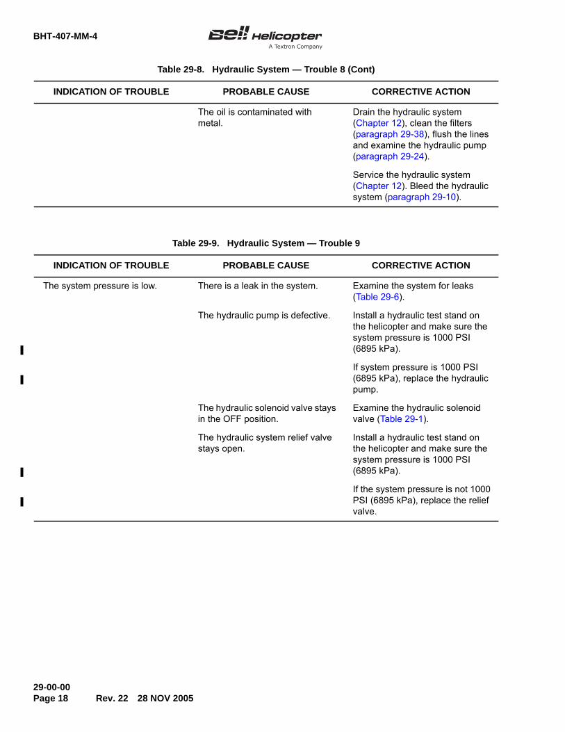
The oil is contaminated with metal.
Drain the hydraulic system (Chapter 12), clean the filters (paragraph 29-38), flush the lines and examine the hydraulic pump (paragraph 29-24).
Service the hydraulic system (Chapter 12). Bleed the hydraulic system (paragraph 29-10).
Table 29-8. Hydraulic System — Trouble 8 (Cont)
INDICATION OF TROUBLE PROBABLE CAUSE CORRECTIVE ACTION
Table 29-9. Hydraulic System — Trouble 9
INDICATION OF TROUBLE PROBABLE CAUSE CORRECTIVE ACTION
The system pressure is low. There is a leak in the system. Examine the system for leaks (Table 29-6).
The hydraulic pump is defective. Install a hydraulic test stand on the helicopter and make sure the system pressure is 1000 PSI (6895 kPa).
If system pressure is 1000 PSI (6895 kPa), replace the hydraulic pump.
The hydraulic solenoid valve stays in the OFF position.
Examine the hydraulic solenoid valve (Table 29-1).
The hydraulic system relief valve stays open.
Install a hydraulic test stand on the helicopter and make sure the system pressure is 1000 PSI (6895 kPa).
If the system pressure is not 1000 PSI (6895 kPa), replace the relief valve.

BHT-407-MM-4
29-00-0028 NOV 2005 Rev. 22 Page 19
Table 29-10. Hydraulic System — Trouble 10
INDICATION OF TROUBLE PROBABLE CAUSE CORRECTIVE ACTION
The hydraulic pressure fluctuates with the controls motionless.
The oil level in the reservoir assembly is low.
Examine the hydraulic system for leaks (Table 29-6).
Service the hydraulic system (Chapter 12).
The hydraulic filters are blocked. Replace the hydraulic filters. If clogged indicator not extended, send to O/H facility.
Hydraulic system relief valve stays open.
Install a hydraulic test stand on the helicopter and make sure the system pressure is 1000 PSI (6895 kPa).
If the system pressure is not 1000 PSI (6895 kPa), replace the relief valve.
The hydraulic pump pressure regulator is defective.
Install a hydraulic test gauge on the helicopter and make sure the system pressure is 1000 PSI (6895 kPa) (run helicopter).
If system pressure is fluctuating, replace the hydraulic pump.

BHT-407-MM-4
29-00-00Page 20 Rev. 22 28 NOV 2005
Figure 29-2. Hydraulic System — Schematic

BHT-407-MM-4
29-00-0028 NOV 2005 Rev. 22 Page 21
29-5. HYDRAULIC SYSTEM — LEAKAGELIMITS
This section shows the permitted external leakage ofthe hydraulic system components that are in serviceon the helicopter and some procedures on how tomeasure the external leakage.
29-6. LEAKAGE LIMITS — SCOPE
The leakage limits specified are for the components inthe helicopter hydraulic system. The intent is to keepthe replacement of serviceable hydraulic componentsto a minimum. These leakage limits can be differentfrom the leakage limits that are used for new oroverhauled components. Do not use these leakagelimits to accept or reject components for benchfunctional tests or for systems on a new helicopters.These leakage limits are not applicable toindependently closed compartment hydraulics, suchas the viscous dampers or liquid springs.
29-7. LEAKAGE LIMITS — CAUSES OFLEAKAGE
Some leakage is correct for the reasons that follow:
• a film of hydraulic fluid is found on the metalsurfaces, such as piston rods and istransmitted through the seals, this film isnecessary to lubricate the seals
• the pressure and the temperature varies andcauses distortion of the seals
• the seals get a permanent form after sometime
29-8. LEAKAGE LIMITS — LEAKAGE TYPES
Leakage rate is established by a quantity of fluid lostversus a period of time. Accumulation of fluid incavities or on flat surfaces may appear worst than theactual leakage rate. The leak has to be evaluated asper Table 29-11.
There are two types of external leakages in thehydraulic system:
Acceptable leakage (permitted leakage).More than permitted leakage rate is based on theexceedance of Table 29-11.
It is also possible to have a large quantity ofcomponents with permitted leakages. The sum of theleakages can be grouped and considered as morethan permitted leakage.
1. More than permitted leakage – Fluid leakagesurpasses the limit when:
• the leakage causes the fluid in the reservoirassembly to decrease to an unserviceablelevel during regular operation
• the leakage can start a fire
• the leakage will change the airworthiness ofthe helicopter
2. Permitted leakage – Permitted leakage is verysmall and has no change on the airworthiness or theoperation of the helicopter. The correction of theleakage is not worth the maintenance time.
29-9. LEAKAGE LIMITS — LEAKAGE CHECKS
The maximum leak rate values are listed inTable 29-11. If the hydraulic system was off (in a nonpressurized condition) for some time. Do not do theleak rate tests immediately after you start the system.Start the system and operate the components severaltimes. Clean all the leaked hydraulic fluid before youstart the test.
1. When you cannot see if the component hasleakage, measure the leakage on a flat surface. Usethe structure below the component or put a panelbelow the component for this reason. Clean thesurface, put one drop of fluid on the area, and let itbecome stable. Make a mark around the area with agrease pencil and clean off the fluid. Pressurize andoperate the component. Compare the permittedleakage of the component from Table 29-11 to theidentified one in the drop area.
2. When you can see the leakage of a component,pressurize and operate the component until a dropfalls. Continue to operate the component and measurethe time until the subsequent drop falls to find theleakage rate.
3. For the tests that require long time, clean thesurface and let it dry. Do not use solvent. After youoperate the system, use a blotter or a white cloth.
BHT-407-MM-4
29-00-00Page 22 Rev. 22 28 NOV 2005
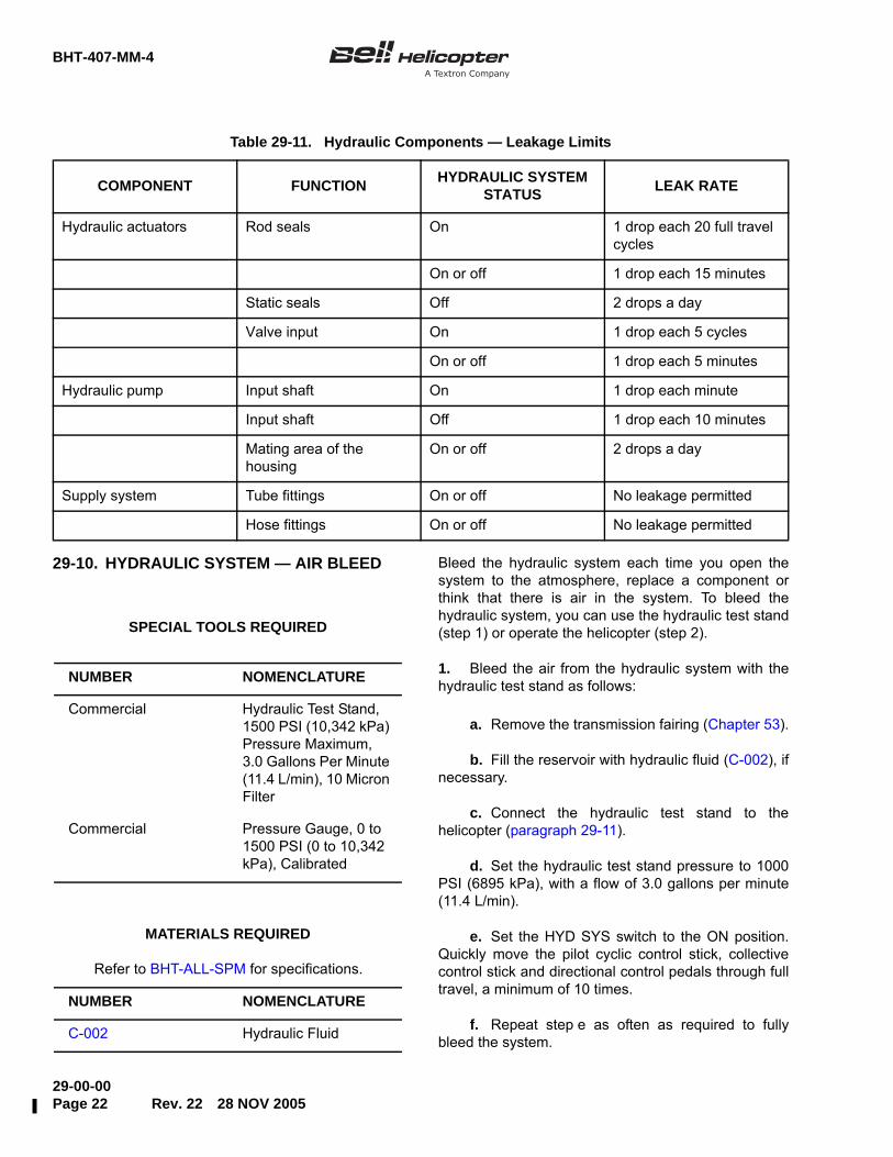
29-10. HYDRAULIC SYSTEM — AIR BLEED Bleed the hydraulic system each time you open thesystem to the atmosphere, replace a component orthink that there is air in the system. To bleed thehydraulic system, you can use the hydraulic test stand(step 1) or operate the helicopter (step 2).
1. Bleed the air from the hydraulic system with thehydraulic test stand as follows:
a. Remove the transmission fairing (Chapter 53).
b. Fill the reservoir with hydraulic fluid (C-002), ifnecessary.
c. Connect the hydraulic test stand to thehelicopter (paragraph 29-11).
d. Set the hydraulic test stand pressure to 1000PSI (6895 kPa), with a flow of 3.0 gallons per minute(11.4 L/min).
e. Set the HYD SYS switch to the ON position.Quickly move the pilot cyclic control stick, collectivecontrol stick and directional control pedals through fulltravel, a minimum of 10 times.
f. Repeat step e as often as required to fullybleed the system.
Table 29-11. Hydraulic Components — Leakage Limits
COMPONENT FUNCTION HYDRAULIC SYSTEM STATUS LEAK RATE
Hydraulic actuators Rod seals On 1 drop each 20 full travel cycles
On or off 1 drop each 15 minutes
Static seals Off 2 drops a day
Valve input On 1 drop each 5 cycles
On or off 1 drop each 5 minutes
Hydraulic pump Input shaft On 1 drop each minute
Input shaft Off 1 drop each 10 minutes
Mating area of the housing
On or off 2 drops a day
Supply system Tube fittings On or off No leakage permitted
Hose fittings On or off No leakage permitted
SPECIAL TOOLS REQUIRED
NUMBER NOMENCLATURE
Commercial Hydraulic Test Stand, 1500 PSI (10,342 kPa) Pressure Maximum, 3.0 Gallons Per Minute (11.4 L/min), 10 Micron Filter
Commercial Pressure Gauge, 0 to 1500 PSI (0 to 10,342 kPa), Calibrated
Refer to BHT-ALL-SPM for specifications.
MATERIALS REQUIRED
NUMBER NOMENCLATURE
C-002 Hydraulic Fluid
BHT-407-MM-4
29-00-0029 AUG 2011 Rev. 32 Page 23ECCN EAR99
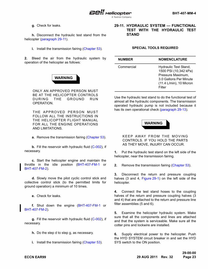
g. Check for leaks.
h. Disconnect the hydraulic test stand from thehelicopter (paragraph 29-11).
i. Install the transmission fairing (Chapter 53).
2. Bleed the air from the hydraulic system byoperation of the helicopter as follows:
WARNING
ONLY AN APPROVED PERSON MUSTBE AT THE HELICOPTER CONTROLSDURING THE GROUND RUNOPERATION.
THE APPROVED PERSON MUSTFOLLOW ALL THE INSTRUCTIONS INTHE HELICOPTER FLIGHT MANUALFOR ALL THE ENGINE OPERATIONSAND LIMITATIONS.
a. Remove the transmission fairing (Chapter 53).
b. Fill the reservoir with hydraulic fluid (C-002), ifnecessary.
c. Start the helicopter engine and maintain thethrottle in the idle position (BHT-407-FM-1 orBHT-407-FM-2).
d. Slowly move the pilot cyclic control stick andcollective control stick (to the permitted limits forground operation) a minimum of 10 times.
e. Check for leaks.
f. Shut down the engine (BHT-407-FM-1 orBHT-407-FM-2).
g. Fill the reservoir with hydraulic fluid (C-002), ifnecessary.
h. Do the step d to step g, as necessary.
i. Install the transmission fairing (Chapter 53).
29-11. HYDRAULIC SYSTEM — FUNCTIONALTEST WITH THE HYDRAULIC TESTSTAND
Use the hydraulic test stand to do the functional test ofalmost all the hydraulic components. The transmissionoperated hydraulic pump is not included because ithas its own operational check (paragraph 29-13).
WARNING
KEEP AWAY FROM THE MOVINGCONTROLS. IF YOU HOLD THE PARTSAS THEY MOVE, INJURY CAN OCCUR.
1. Put the hydraulic test stand on the left side of thehelicopter, near the transmission fairing.
2. Remove the transmission fairing (Chapter 53).
3. Disconnect the return and pressure couplinghalves (3 and 4, Figure 29-1) on the left side of thehelicopter.
4. Connect the test stand hoses to the couplinghalves of the return and pressure coupling halves (3and 4) that are attached to the return and pressure linefilter assemblies (5 and 6).
5. Examine the helicopter hydraulic system. Makesure that all the components and lines are attachedand that the system is serviceable. Make sure all thecotter pins and lockwire are installed.
6. Supply electrical power to the helicopter. Pushthe HYD SYSTEM circuit breaker in and set the HYDSYS switch to the ON position.
SPECIAL TOOLS REQUIRED
NUMBER NOMENCLATURE
Commercial Hydraulic Test Stand, 1500 PSI (10,342 kPa) Pressure Maximum, 3.0 Gallons Per Minute (11.4 L/min), 10 Micron Filter

BHT-407-MM-4
29-00-00Page 24 Rev. 32 29 AUG 2011 ECCN EAR99
7. Set the test stand to supply a minimum of 3.0gallons per minute (11.4 L/min) flow. Adjust thepressure compensator to get 1000 PSI (6895 kPa) atthe required flow. Apply pressure to the hydraulicsystem for a minimum of 15 minutes. Do the test asfollows:
WARNING
KEEP AWAY FROM THE MOVINGCONTROLS. IF YOU HOLD THE PARTSAS THEY MOVE, INJURY CAN OCCUR.
a. While you slowly move the cyclic control stick,collective control stick and the directional controlpedals, monitor the hydraulic servo actuators. Makesure that they move freely and do not rub othercomponents. Examine the hoses for movement thatcan loosen the fittings.
b. Slowly increase the hydraulic test standpressure while you touch the relief valve (7,Figure 29-1). You will feel the relief valve open at 1225±150 PSI (8446 ±1034 kPa). If the relief valve does notopen at these limits, replace it.
c. Slowly decrease the hydraulic test standpressure while you touch the relief valve (7). You willfeel the relief valve (7) close at about 1075 PSI(7412 kPa).
d. Set the hydraulic test stand pressure to1000 PSI (-25/+50 PSI) (6895 kPa (-172/+344 kPa)).Set the HYD SYS switch to the OFF position. Thiscloses the solenoid valve (8). Move the pilot cycliccontrol stick, collective control stick and the directionalcontrol pedals. They will require more force to movecompared to when the HYD SYS switch is set to theON position.
e. Set the HYD SYS switch to the ON position.Decrease hydraulic pressure on the test stand to 0 PSI(0 kPa). Slowly increase the pressure while you movethe pilot cyclic control stick, collective control stick andthe directional control pedals. The change frommechanical to hydraulic operation must occur at 144±44 PSI (993 ±303 kPa). The check valves (4,Figure 29-14) that are part of the servo valve do thisoperation. Make sure this condition is met for thecollective, cyclic and directional controls.
f. Decrease hydraulic pressure on the test standto 0 PSI (0 kPa). Push or pull the rod end of eachservo actuator with approximately 50 pounds (222 N)force. The piston rods must not move.
g. Examine the hydraulic system for leaks(paragraph 29-5).
h. Disconnect the hydraulic test stand. Connectthe return and pressure coupling halves (3 and 4,Figure 29-1).
i. Service the hydraulic system (Chapter 12).
j. Install the transmission fairing (Chapter 53).
29-12. HYDRAULIC SYSTEM — FUNCTIONALTEST WITH THE HELICOPTERHYDRAULIC PUMP
If a hydraulic test stand is not available, a functionaltest can be done with the transmission operatedhydraulic pump. This test is not as complete as thetest done with the hydraulic test stand.
1. Remove the transmission fairing (Chapter 53).
2. Examine the helicopter hydraulic system. Makesure all the components and lines are attached andthe system is serviceable. Make sure all the cotter pinsand lockwire are installed and all flight controls areairworthy.
WARNING
ONLY AN APPROVED PERSON MUSTBE AT THE HELICOPTER CONTROLSDURING THE GROUND RUNOPERATION.
THE APPROVED PERSON MUSTFOLLOW ALL OF THE INSTRUCTIONS INTHE HELICOPTER FLIGHT MANUALFOR ALL OF THE ENGINE OPERATIONSAND LIMITATIONS.
3. Start the helicopter engine and maintain thethrottle in the idle position (BHT-407-FM-1 orBHT-407-FM-2).

BHT-407-MM-4
29-00-0029 AUG 2011 Rev. 32 Page 25ECCN EAR99
WARNING
KEEP AWAY FROM THE MOVINGCONTROLS. IF YOU HOLD THE PARTSAS THEY MOVE, INJURY CAN OCCUR.
4. Slowly move the cyclic control stick, collectivecontrol stick and the directional control pedals to thepermitted limits for the ground operation. Monitor thehydraulic servo actuators. Make sure they move freelyand that they do not rub other components. Examinethe hoses for movement that can loosen the fittings.
5. Set the HYD SYS switch to the OFF position.This closes the solenoid valve (8, Figure 29-1). Movethe pilot cyclic, collective and directional controls.They will require more force to move compared towhen the HYD SYS switch is set to the ON position.
6. Set the HYD SYS switch to the ON position. After15 minutes of operation, examine the hydraulic systemfor leaks (paragraph 29-5).
7. Shut down the engine (BHT-407-FM-1 orBHT-407-FM-2).
8. Verify the hydraulic fluid for discoloration andlevel hydraulic filters for clogged indicators. If any ofthese conditions exist, refer to troubleshooting(paragraph 29-4).
9. Install the transmission fairing.
29-13. HYDRAULIC PUMP — OPERATIONALCHECK
1. Remove the transmission fairing (Chapter 53).
2. Remove the plug from the test port on one of the
actuators (Chapter 67). Connect a calibrated pressure
gauge with a range of 0 to 1500 PSI (0 to 10,342 kPa).
WARNING
ONLY AN APPROVED PERSON MUST
BE AT THE HELICOPTER CONTROLS
DURING THE GROUND RUN
OPERATION.
THE APPROVED PERSON MUST
FOLLOW ALL OF THE INSTRUCTIONS IN
THE HELICOPTER FLIGHT MANUAL
FOR ALL OF THE ENGINE OPERATIONS
AND LIMITATIONS.
3. Start the helicopter engine. After warm up,
position the throttle to the FLY position (100 NR)
(BHT-407-FM-1 or BHT-407-FM-2). Make sure that the
pressure gauge shows 1000 PSI (-25/+50 PSI)
(6895 kPa (-172/+344 kPa)). If the hydraulic system
pressure is not at this pressure, the hydraulic pump
will have to be replaced.
4. Shut down the engine (BHT-407-FM-1 or
BHT-407-FM-2).
5. If the hydraulic pressure is correct, install the test
port plug and safety with lockwire (C-405). Put the
helicopter in the flight configuration.
6. Install the transmission fairing (Chapter 53).
SPECIAL TOOLS REQUIRED
NUMBER NOMENCLATURE
Commercial Pressure Gauge, 0 to 1500 PSI (0 to 10,342 kPa), Calibrated
Refer to BHT-ALL-SPM for specifications.
MATERIALS REQUIRED
NUMBER NOMENCLATURE
C-405 Lockwire
BHT-407-MM-4
29-00-00Page 26 Rev. 22 28 NOV 2005
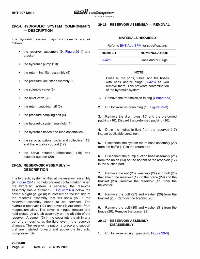
29-14. HYDRAULIC SYSTEM COMPONENTS— DESCRIPTION
The hydraulic system major components are asfollows:
• the reservoir assembly (9, Figure 29-1) andbracket
• the hydraulic pump (10)
• the return line filter assembly (5)
• the pressure line filter assembly (6)
• the solenoid valve (8)
• the relief valve (7)
• the return coupling half (3)
• the pressure coupling half (4)
• the hydraulic system manifold (1)
• the hydraulic hoses and tube assemblies
• the servo actuators (cyclic and collective) (18)and the actuator support (17)
• the servo actuator (directional) (19) andactuator support (20)
29-15. RESERVOIR ASSEMBLY —DESCRIPTION
The hydraulic system is filled at the reservoir assembly(9, Figure 29-1). To help prevent contamination whenthe hydraulic system is serviced, the reservoirassembly has a strainer (6, Figure 29-3) below thecover. A sight gauge (8) is installed on the left side ofthe reservoir assembly that will show you if thereservoir assembly needs to be serviced. Thehydraulic reservoir (17) and cover (4) are made frommagnesium alloy. The cover is hinged forward andheld closed by a latch assembly on the aft side of thereservoir. A screen (5) in the cover lets the air in andout of the housing, as the fluid level in the reservoirchanges. The reservoir is put on a brace and supportthat are installed forward and above the hydraulicpump assembly.
29-16. RESERVOIR ASSEMBLY — REMOVAL
NOTE
Close all the ports, tubes, and the hoseswith caps and/or plugs (C-428) as youremove them. This prevents contaminationof the hydraulic system.
1. Remove the transmission fairing (Chapter 53).
2. Cut lockwire on drain plug (15, Figure 29-3).
3. Remove the drain plug (15) and the preformedpacking (16). Discard the preformed packing (16).
4. Drain the hydraulic fluid from the reservoir (17)into an applicable container.
5. Disconnect the system return hose assembly (20)from the baffle (11) in the return port.
6. Disconnect the pump suction hose assembly (21)from the union (13) on the bottom of the reservoir (17)in the suction port.
7. Remove the nut (25), washers (24) and bolt (23)that attach the reservoir (17) to the brace (29) and thebracket (26). Remove the reservoir (17) from thehelicopter.
8. Remove the bolt (27) and washer (28) from thebracket (26). Remove the bracket (26).
9. Remove the bolt (30) and washer (31) from thebrace (29). Remove the brace (29).
29-17. RESERVOIR ASSEMBLY —DISASSEMBLY
1. Cut lockwire on sight gauge (8, Figure 29-3).
Refer to BHT-ALL-SPM for specifications.
MATERIALS REQUIRED
NUMBER NOMENCLATURE
C-428 Caps and/or Plugs

BHT-407-MM-4
29-00-0028 NOV 2005 Rev. 22 Page 27
Figure 29-3. Hydraulic System Manifold — Maintenance Practices

BHT-407-MM-4
29-00-00Page 28 Rev. 22 28 NOV 2005
2. Remove the sight gauge (8) and preformedpacking (9). Discard the preformed packing (9).
3. Remove the baffle (11) and preformed packing(12). Discard the preformed packing (12).
4. Remove the union (13) and preformed packing(14). Discard the preformed packing (14).
5. Remove pin (22) from latch assembly (10).
6. Open the latch assembly (10) and release thecover (4).
7. The strainer (6) is sealed to the inner lip of thereservoir (17). Use a blunt tool and carefully removethe strainer (6).
8. Remove and discard the gasket (7).
9. Remove the plug (19) and preformed packing(18). Discard the preformed packing (18).
29-18. RESERVOIR ASSEMBLY — INSPECTIONAND REPAIR
1. Examine the brace (29, Figure 29-3) and thebracket (26) for damage.
2. Examine the reservoir (17) and cover (4) fordamage and signs of leakage.
3. Refer to BHT-ALL-SPM, for instructions on howto repair small surface scratches that get on themagnesium alloy.
4. Examine the tape at the attach points for breaks.Make sure that you cannot see the magnesium alloy.Replace all damaged barrier tape (C-430).
5. Examine the sight gauge (8, Figure 29-3) forcracks and stains. If you can see the hydraulic fluidthrough the sight gauge (8), it is serviceable.
6. Examine the strainer (6) and make sure there isno tears or dents in the screen that can permit largeparticles to get in. If you find a defect, replace thestrainer (6).
7. Examine the latch assembly (10) for distortionand wear that can cause unsatisfactory operation.
8. Examine the screen (5) for tears and blockage.Clean or replace the screen (5), as necessary.
9. Examine all the fittings, plugs and the baffle. Ifyou find damage, replace the component.
29-19. RESERVOIR ASSEMBLY — ASSEMBLY
NOTE
Lubricate all the preformed packings andretainers with hydraulic fluid (C-002) beforeyou install them. Apply a layer of hydraulicfluid (C-002) to the threads of all the fittingsbefore you install them.
1. Install the preformed packing (9, Figure 29-3) onthe sight gauge (8).
2. Install the sight gauge (8) in the reservoir (17).Safety the sight gauge (8) with lockwire (C-405).
3. Install the preformed packing (12) on the baffle(11).
4. Install the baffle (11) in the reservoir (17).
Refer to BHT-ALL-SPM for specifications.
MATERIALS REQUIRED
NUMBER NOMENCLATURE
C-430 Barrier Tape
Refer to BHT-ALL-SPM for specifications.
MATERIALS REQUIRED
NUMBER NOMENCLATURE
C-002 Hydraulic Fluid
C-314 Adhesive
C-405 Lockwire
T

BHT-407-MM-4
29-00-0028 NOV 2005 Rev. 22 Page 29
5. Install the preformed packing (14) on the union(13).
6. Install the union (13) in the reservoir (17).
7. Install the preformed packing (16) on the drainplug (15).
8. Install the drain plug (15) in the reservoir (17).Safety the drain plug (15) with lockwire (C-405).
9. Install the preformed packing (18) on the plug(19).
10. Install the plug (19) in the reservoir (17).
11. Install the gasket (7) in the reservoir (17), in thegroove of the flange and lip.
12. Prepare inside flange of reservoir (17) and matingsurface of strainer (6) for silicone bonding(BHT-ALL-SPM). Apply 1/16 inch (4.32 mm) bead ofadhesive (C-314) to the mating faces of the reservoir(17) and the strainer (6).
13. Install the strainer (6) in the reservoir (17). Makesure the strainer (6) is tightly seated in the adhesive(C-314). Remove adhesive squeeze-out and allow tocure.
14. Close cover (4). Install pin (22) in latch assembly(10).
29-20. RESERVOIR ASSEMBLY —INSTALLATION
CAUTION
CLOSE ALL THE PORTS, TUBES ANDHOSES WITH CAPS AND/OR PLUGS(C-428) AS YOU REMOVE THEM. THISWILL PREVENT CONTAMINATION OFUNWANTED MATERIALS INTO THEHYDRAULIC SYSTEM.
NOTE
To connect a hose, start the nut by handand use a backup wrench on the hosefitting, to stop the twists in the hose.
NOTE
Lubricate all the preformed packings andretainers with hydraulic fluid (C-002) beforeyou install them. Apply a layer of hydraulicfluid (C-002) to the threads of all the fittingsbefore you install them.
1. Clean and flush the reservoir with hydraulic fluid(C-002).
2. Examine the tape at the attach points for breaks.Make sure that you cannot see bare magnesium alloy.Replace all damaged barrier tape (C-430).
3. Apply a layer of corrosion preventive compound(C-104) on all the bolt shanks.
4. Put the bracket (26, Figure 29-3) on thehelicopter and attach with the bolt (27) and washer(28).
5. Put the brace (29) in position and attach with bolt(30) and washer (31).
Refer to BHT-ALL-SPM for specifications.
MATERIALS REQUIRED
NUMBER NOMENCLATURE
C-002 Hydraulic Fluid
C-101 Corrosion Preventive Compound
C-104 Corrosion Preventive Compound
C-428 Caps and/or Plugs
C-430 Barrier Tape
Refer to BHT-ALL-SPM for specifications.
MATERIALS REQUIRED (Cont)
NUMBER NOMENCLATURE

BHT-407-MM-4
29-00-00Page 30 Rev. 22 28 NOV 2005
6. Put the reservoir (17) in position on the brace (29)and the bracket (26) and attach with the bolt (23),washers (24) and nut (25).
7. Connect the pump suction hose assembly (21) tothe union (13).
8. Connect the system return hose assembly (20) tothe baffle (11).
9. Apply a layer of corrosion preventive compound(C-101) to all the bolt heads, nuts and the washers.
10. Fill the hydraulic system (Chapter 12).
11. Bleed the system (paragraph 29-10).
12. Install the transmission fairing (Chapter 53).
29-21. HYDRAULIC SYSTEM PUMP —DESCRIPTION
The hydraulic system pump (Figure 29-4) is mountedon a housing assembly that is mounted to thetransmission lower case. The hydraulic system pump(5) is operated by the transmission oil pump through ashaft assembly. The transmission output is protectedby the shaft assembly (18). The shaft assembly (18)has a shear strength of 150 to 225 inch-pounds (16.9to 25.4 Nm).
The hydraulic pump is a multi-piston, constantpressure, variable delivery type. Continuous output israted at 1000 PSI (-25/+50 PSI) (6895 kPa (-172/+344kPa)). The hydraulic system pump (5) has four markedports: the inlet, the outlet, the seepage drain and thecase drain. Only three ports are used on 407helicopters, the seepage drain port is sealed.
29-22. HYDRAULIC SYSTEM PUMP — REMOVAL
CAUTION
CLOSE ALL THE PORTS, TUBES ANDHOSES WITH CAPS AND/OR PLUGS(C-428) AS YOU REMOVE THEM. THISWILL PREVENT CONTAMINATION OFUNWANTED MATERIALS INTO THEHYDRAULIC SYSTEM.
1. Remove the transmission fairing (Chapter 53).
2. Drain the reservoir assembly (Chapter 12).
3. Put a container on the maintenance platform,below the hydraulic system pump (5, Figure 29-4).
When you remove the hose assemblies, the containerwill catch the hydraulic fluid that is released.
4. Disconnect the pump suction hose assembly (1).
5. Disconnect the system pressure hose assembly(15).
6. Disconnect the case drain hose assembly (8).
7. Remove the nut (11) and washer (10) from thehydraulic system pump (5).
8. Remove the hydraulic system pump (5).
9. Remove and discard the gasket (9).
29-23. HYDRAULIC SYSTEM PUMP —DISASSEMBLY
Refer to BHT-ALL-SPM for specifications.
MATERIALS REQUIRED
NUMBER NOMENCLATURE
C-428 Caps and/or Plugs
Refer to BHT-ALL-SPM for specifications.
MATERIALS REQUIRED
NUMBER NOMENCLATURE
C-428 Caps and/or Plugs

BHT-407-MM-4
29-00-0028 NOV 2005 Rev. 22 Page 31
Figure 29-4. Hydraulic System Pump — Maintenance Practices

BHT-407-MM-4
29-00-00Page 32 Rev. 22 28 NOV 2005
CAUTION
CLOSE ALL THE PORTS, TUBES ANDHOSES WITH CAPS AND/OR PLUGS(C-428) AS YOU REMOVE THEM. THISWILL PREVENT CONTAMINATION OFUNWANTED MATERIALS INTO THEHYDRAULIC SYSTEM.
NOTE
The hydraulic pump must be returned to themanufacturer or to an approved overhaulfacility for all repairs or overhaul of theinternal components.
1. Remove the elbow (3, Figure 29-4), nut (7),retainer (17) and the preformed packing (6). Discardthe retainer (17) and the preformed packing (6).
2. Remove the elbow (16), nut (2), retainer (13) andpreformed packing (4). Discard the retainer (13) andthe preformed packing (4).
3. Remove the union (14) and the preformedpacking (12). Discard the preformed packing (12).
4. On pump part number 206-076-030-111 (PreTB 407-01-30), remove the driveshaft assembly (18).
5. On pump part number 206-076-030-117 (Post TB407-01-30), remove the input shaft (19). (paragraph29-26).
29-24. HYDRAULIC SYSTEM PUMP —INSPECTION
1. With the hydraulic system pump (5, Figure 29-4)in position, examine for a tight installation to thehousing assembly on the transmission lower case.
2. With the hydraulic system pump (5) in position,look for leakage. All leakage that forms a drop is notpermitted.
3. With the hydraulic system pump (5) in position,examine the driveshaft seal for leakage. The
driveshaft seal is not permitted to leak more than 1drop each 10 minutes.
4. With the hydraulic system pump (5) removed,examine the inlet ports for damage to the threads.Examine the drive shaft for damage to the splines. Ifthe hydraulic system pump (5) is damaged, replace it.
5. Examine the hose assemblies and their fittings(1, 8 and 15, Figure 29-4) for damage, corrosion,distorted threads, and leakage.
29-25. HYDRAULIC PUMP DRIVE — INSPECTION,PUMP ASSEMBLY P/N 206-076-030-111
NOTE
Effective on helicopter S/N 53000 through53408 and 53421 through 53474 Pre TB407-01-30.
With the pump removed:
1. Clean the shafts with drycleaning solvent (C-304)and dry (hydraulic pump, driveshaft, transmissionoutput shaft).
2. Examine the splines of the driveshaft assembly(18, Figure 29-4) and visible splines of externaldriveshaft (20) for wear, cracks, and corrosion pittingwith a 10X magnifying glass.
3. Refer to Figure 29-5 for driveshaft wear limitdimensions.
4. Service the driveshaft splines as per Chapter 12.
5. Refer to paragraph 29-27 for pump assembly andparagraph 29-28 for installation.
Refer to BHT-ALL-SPM for specifications.
MATERIALS REQUIRED
NUMBER NOMENCLATURE
C-304 Drycleaning Solvent
BHT-407-MM-4
29-00-0028 NOV 2005 Rev. 22 Page 33
Figure 29-5. Hydraulic Pump External Driveshaft and Input Driveshaft Assembly — Wear Limits

BHT-407-MM-4
29-00-00Page 34 Rev. 30 8 APR 2011 ECCN EAR99
29-26. HYDRAULIC PUMP DRIVE — INSPECTION,PUMP ASSEMBLY P/N 206-076-030-117
NOTE
Effective on helicopters S/N 53409 through53420 and 53475 and subsequent or PostTB 407-01-30.
With the pump removed:
NOTE
The force needed to remove input shaft (4,Figure 29-6) can vary due to differences inretainer ring spring load.
1. Remove the input shaft (4) from the hydraulicpump (7) as follows:
a. Hold input shaft (4) tight and tap housinglightly with a small mallet (plastic type) to separateinput shaft from hydraulic pump.
2. Remove the interconnect (Vespel) adaptor (3)from the input shaft (4, Figure 29-6).
3. Clean the input shaft (4) and the interconnect(Vespel) adaptor (3) with drycleaning solvent (C-304)and dry.
4. Examine the splines on the interconnect (Vespel)adaptor (3) for wear (Figure 29-7).
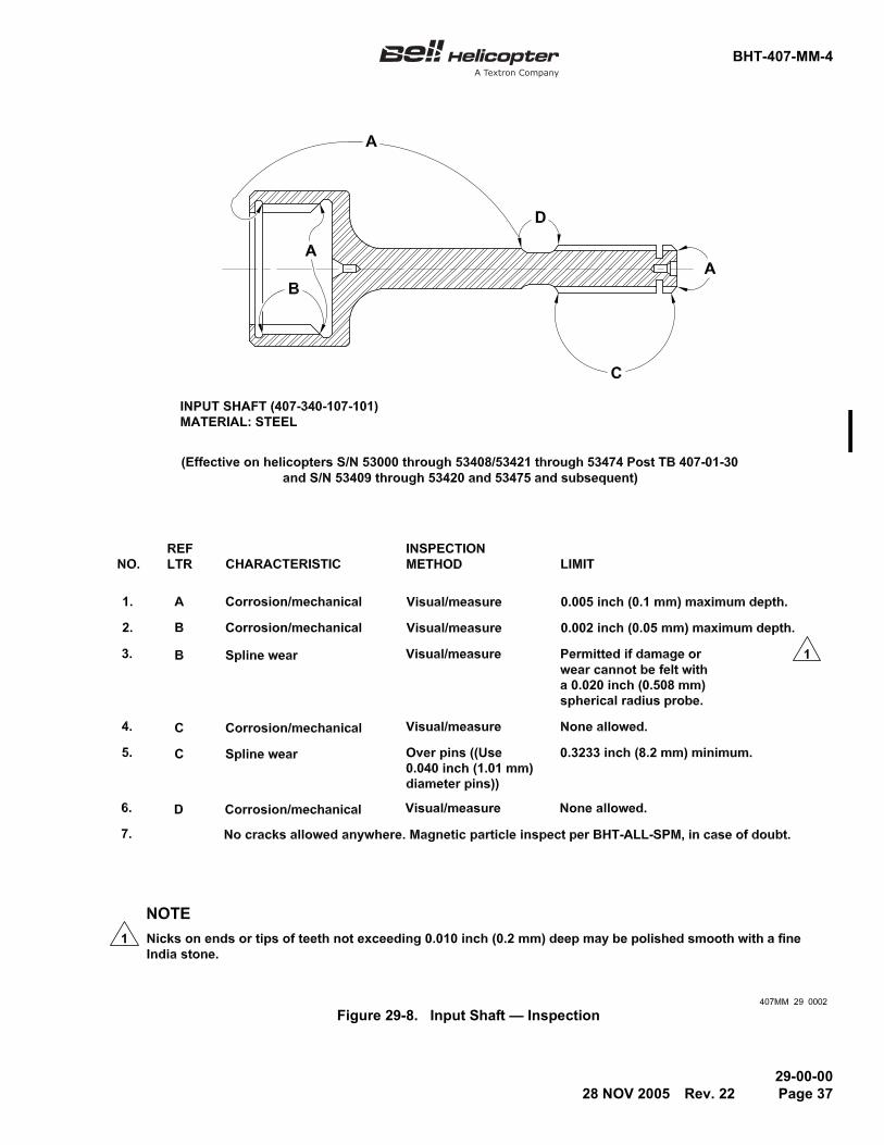
5. Inspect male and female splines on the inputshaft for wear (Figure 29-8).
6. Refer to paragraph 29-27 for pump assembly andparagraph 29-28 for installation.
29-27. HYDRAULIC SYSTEM PUMP —ASSEMBLY
NOTE
Lubricate all the preformed packings andretainers with hydraulic fluid (C-002) beforeyou install them. Apply a layer of hydraulicfluid (C-002) to the threads of all fittingsbefore you install them.
1. To install a new hydraulic system pump (5,Figure 29-4), remove the shipping plugs. Fully drainthe preservation oil. Close all the ports with caps and/or plugs (C-428). Use the following assemblyinstructions:
2. Apply grease (C-525) or grease (C-561) to thesplines on the driveshaft assembly (18, Figure 29-4),and visible splines of external driveshaft (20), withpump part number 206-076-030-111, Pre TB407-01-30.
3. With pump, part number 206-076-030-117 (PostTB 407-01-30) install the shaft assembly (4,Figure 29-6), as follows:
a. Install retainer ring (5) on input shaft (4).
b. Lubricate male splines of the input shaft (4)with grease (C-525) or grease (C-561). Use a smallamount of grease (C-525) or grease (C-561) to holdspring (6) in input shaft end (4).
Refer to BHT-ALL-SPM for specifications.
MATERIALS REQUIRED
NUMBER NOMENCLATURE
C-304 Drycleaning Solvent
Refer to BHT-ALL-SPM for specifications.
MATERIALS REQUIRED
NUMBER NOMENCLATURE
C-002 Hydraulic Fluid
C-428 Caps and/or Plugs
C-525 Spline Lubricant Grease(MIL-G-81827) Royco 22MS(Alt. Aeroshell 23C)
C-561 Grease

BHT-407-MM-4
29-00-008 APR 2011 Rev. 30 Page 35ECCN EAR99
Figure 29-6. Hydraulic Input Shaft — Installation
NO OBJECT BEYOND THIS POINT 407MM_29_0001_c01
5. Retainer ring (25399)
7. Hydraulic pump (206-076-030-117)
3. Interconnect adapter (407-340-108-101)2. Retaining ring (407-340-109-101)
4. Input shaft (407-340-107-101)
6. Spring (67588)
1. Gasket (406-376-001-101)
Effective on helicopters S/N 53000 through 53408 /53421 through
Use grease (C-525) or (C-561) to hold spring and to lubricate male
Install dry. Lubrication is not required on splines of interconnect
NOTES1.
2
3
6
7
5
43
21
3
2
2
53474 Post TB 407-01-30 and S/N 53409 through 53420 and 53475
adapter (3) or female splines of input shaft (4).
and subsequent.
splines of input shaft (4).

BHT-407-MM-4
29-00-00Page 36 Rev. 22 28 NOV 2005
Figure 29-7. Interconnect Adapter — Inspection
BHT-407-MM-4
29-00-0028 NOV 2005 Rev. 22 Page 37
Figure 29-8. Input Shaft — Inspection
BHT-407-MM-4
29-00-00Page 38 Rev. 30 8 APR 2011 ECCN EAR99
c. Invert pump (7) and insert input shaft (4) withassembled retainer ring and spring into internaldriveshaft and press in until retainer ring snaps intogroove of internal driveshaft.
NOTE
Do not apply grease (C-525) or grease(C-561) to the splines of the interconnectadapter (3) or the female splines of theinput shaft (4). The use of grease lubricantcan result in deterioration of the adapter.
d. Install the adapter (3) and the retaining ring (2)into internal splined end of the input shaft (4).
4. Install the preformed packing (12, Figure 29-4) onthe union (14).
5. Install the union (14) in the hydraulic systempump (5) pressure port.
6. Install the nut (2), retainer (13), and preformedpacking (4) on the elbow (16).
7. Install the elbow (16) in the hydraulic systempump (5) suction port.
8. Fill the hydraulic system pump (5) case drain portwith hydraulic fluid (C-002).
9. Install the nut (7), retainer (17), and preformedpacking (6) on the elbow (3).
10. Install the elbow (3) in the hydraulic system pump(5) case drain port.
29-28. HYDRAULIC SYSTEM PUMP —INSTALLATION
NOTE
To connect a hose, start the nut by handand use a backup wrench on the hosefitting, to stop twists in the hose.
1. Install the gasket (9, Figure 29-4) on the housingassembly.
2. Service the splines as per Chapter 12.
3. Put the hydraulic system pump (5) in position onthe housing assembly mounting studs and attach withthe washer (10) and the nut (11).
4. Connect the case drain hose assembly (8) to theelbow (3).
5. Connect the system pressure hose (15) to theunion (14).
6. Connect the pump suction hose assembly (1) tothe elbow (16).
7. Fill the hydraulic system (Chapter 12). Examineall the connections for leakage.
8. Purge air from the hydraulic system (paragraph29-10).
9. Do a hydraulic pump operational check(paragraph 29-13).
10. Check for leaks.
11. Install the transmission fairing (Chapter 53).
29-29. FILTER ASSEMBLIES —DESCRIPTION
The return line and pressure line filter assemblies (5and 6, Figure 29-1) are installed on a bracket near thereservoir assembly (9), on the left side of the cabinroof. One filter is installed in the pressure line and onein the return line. The two filters have a mechanicalimpending clogged condition red indicator button (5,Figure 29-9). This indicator extends when thedifferential pressure across the filter is 70 ±10 PSI(482 ±69 kPa). The indicator does not work whenhydraulic fluid temperature is less than 35°F (2°C).This prevents incorrect clogged indications. If thehydraulic fluid is cold, the viscosity will change and ahigher differential pressure across the filter will becorrect. If the hydraulic fluid temperature is more than35°F (2°C) the indicator will show the correct conditionof the filter, even if the ambient temperature is lessthan 35°F (2°C).
The return line filter assembly (5, Figure 29-1) is abypass type. The bypass valve is inside the body ofthe return line filter assembly (5). When the differentialpressure across the filter is more than 100 ±25 PSI(689 ±172 kPa), the bypass valve opens. Pressurizedhydraulic oil is then sent directly to the reservoir. Whenthe differential pressure decreases to 65 PSI(448 kPa), the bypass valve closes. The hydraulic oilwill then go through the filter to the reservoir.

BHT-407-MM-4
29-00-0018 JUN 2013 Rev. 36 Page 39Export Classification C, ECCN EAR99
Figure 29-9. Filter Assembly and Element — Maintenance Practices
2. Coupling half
4. Bypass valve5. Red indicator button
11. Union
17. Filter bowl
12. Filter body
21. Washer20. Bolt
22. Nut
OIL
IN OUT
FLOW
1. Coupling half
3. Preformed packing
10. Preformed packing
13. Preformed packing
6. Bolt7. Retainer
9. Preformed packing
15. Preformed packing16. Element
18. Hydraulic system pressure tube assembly
19. Hose assembly
23. Reducer tee24. Preformed packing25. Check valve26. Case drain hose assembly27. Nut28. Retainer29. Preformed packing30. Hydraulic system
return tube assembly31. Filter bracket assembly
8. Preformed packing
19
DETAIL A
SEE DETAIL A FORRETURN LINE FILTER
1
2 3
12
13
14
16
15
17
31
2221
18
1110
20
8
6 5
4
9
7
30
2324
25
26
27
28
29
20 TO 60 IN-LBS(2.86 TO 6.78 Nm)
LOCKWIRE (C-508)
14. Retainer
RETURN LINE FILTER ASSEMBLY
FILTER ASSEMBLY(TYPICAL)
LOCKWIRE (C-405)
1
2
2
1
407_MM_29_0011_c01

BHT-407-MM-4
29-00-00Page 40 Rev. 22 28 NOV 2005
The inspection and cleaning procedures are the samefor the pressure line and return line filter assemblies (5and 6).
The removal and installation procedures are verysimilar for the pressure line and return line filterassemblies (5 and 6). The differences are indicated inthe procedures.
29-30. FILTER ASSEMBLIES —OPERATIONAL CHECK
Perform an operational check of the red indicatorbuttons on the pressure line filter assembly as on thereturn line filter assembly, as follows:
1. Remove the transmission fairing (Chapter 53).
2. Remove the element (16, Figure 29-9).
3. Install the dummy filter element (Workaid No. 1,Figure 29-10).
4. Connect the hydraulic test stand to the helicopter(paragraph 29-11).
5. Set the hydraulic test stand pressure to 1000 PSI(6895 kPa).
6. With the hydraulic system on, move the controlsto their limits of motion several times.
7. Inspect for extension at the red button on the filterhousing assembly. If the button is not extended,disassemble, clean, reassemble and retest the redindicator button. If the button still does not extend,replace the filter housing assembly (paragraph 29-31).
8. If the red indicator button extends during the test,the test is complete. Remove the dummy filter element(Workaid No. 1), reset the red indicator button andinstall a serviceable filter element (paragraph 29-39).
9. Remove the hydraulic test stand.
10. Fill the hydraulic system (Chapter 12).
11. Bleed air from the hydraulic system (paragraph29-10).
12. Install the transmission fairing (Chapter 53).
29-31. FILTER ASSEMBLIES — REMOVAL
CAUTION
CLOSE ALL THE PORTS, TUBES ANDHOSES WITH CAPS AND/OR PLUGS(C-428) AS YOU REMOVE THEM. THISWILL PREVENT CONTAMINATION OFUNWANTED MATERIALS INTO THEHYDRAULIC SYSTEM.
1. Remove the transmission fairing (Chapter 53).
2. Disconnect the coupling half (1, Figure 29-9) fromthe coupling half (2).
3. On the pressure line side, disconnect hydraulicsystem pressure tube assembly (18) from the union(11).
4. On the return line side, disconnect hydraulicsystem return tube assembly (30) from reducer tee(23).
5. On the return line side, disconnect case drainhose assembly (26) from check valve (25).
SPECIAL TOOLS REQUIRED
NUMBER NOMENCLATURE
Workaid No. 1 Dummy Filter Element
Commercial Hydraulic Test Stand1500 PSI (10,342 kPa) Pressure Maximum, 3.0 Gallons Per Minute (11.4 L/min), 10 Micron Filter
Refer to BHT-ALL-SPM for specifications.
MATERIALS REQUIRED
NUMBER NOMENCLATURE
C-428 Caps and/or Plugs
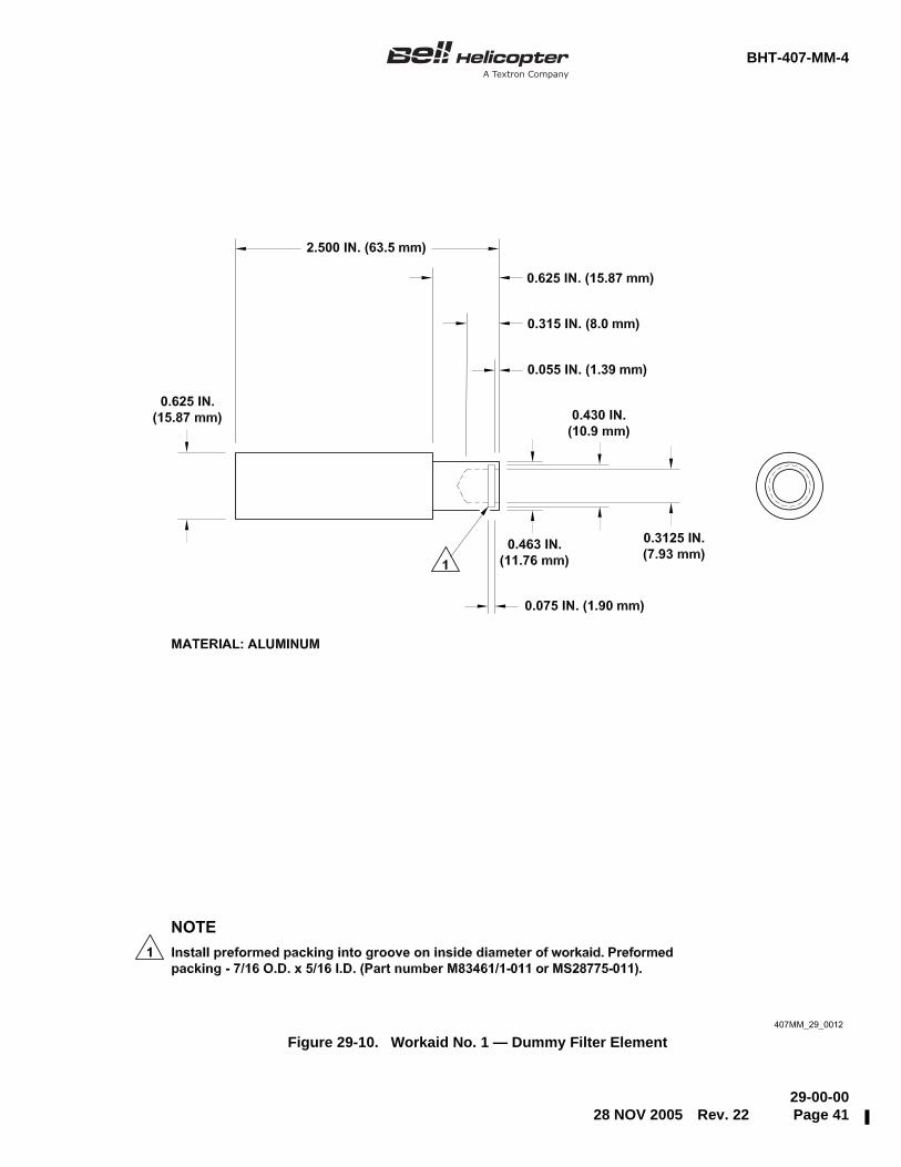
BHT-407-MM-4
29-00-0028 NOV 2005 Rev. 22 Page 41
Figure 29-10. Workaid No. 1 — Dummy Filter Element
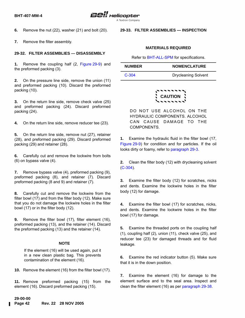
BHT-407-MM-4
29-00-00Page 42 Rev. 22 28 NOV 2005
6. Remove the nut (22), washer (21) and bolt (20).
7. Remove the filter assembly.
29-32. FILTER ASSEMBLIES — DISASSEMBLY
1. Remove the coupling half (2, Figure 29-9) andthe preformed packing (3).
2. On the pressure line side, remove the union (11)and preformed packing (10). Discard the preformedpacking (10).
3. On the return line side, remove check valve (25)and preformed packing (24). Discard preformedpacking (24).
4. On the return line side, remove reducer tee (23).
5. On the return line side, remove nut (27), retainer(28), and preformed packing (29). Discard preformedpacking (29) and retainer (28).
6. Carefully cut and remove the lockwire from bolts(6) on bypass valve (4).
7. Remove bypass valve (4), preformed packing (9),preformed packing (8), and retainer (7). Discardpreformed packing (8 and 9) and retainer (7).
8. Carefully cut and remove the lockwire from thefilter bowl (17) and from the filter body (12). Make surethat you do not damage the lockwire holes in the filterbowl (17) or in the filter body (12).
9. Remove the filter bowl (17), filter element (16),preformed packing (13), and the retainer (14). Discardthe preformed packing (13) and the retainer (14).
NOTE
If the element (16) will be used again, put itin a new clean plastic bag. This preventscontamination of the element (16).
10. Remove the element (16) from the filter bowl (17).
11. Remove preformed packing (15) from theelement (16). Discard preformed packing (15).
29-33. FILTER ASSEMBLIES — INSPECTION
CAUTION
DO NOT USE ALCOHOL ON THEHYDRAULIC COMPONENTS. ALCOHOLCAN CAUSE DAMAGE TO THECOMPONENTS.
1. Examine the hydraulic fluid in the filter bowl (17,Figure 29-9) for condition and for particles. If the oillooks dirty or foamy, refer to paragraph 29-3.
2. Clean the filter body (12) with drycleaning solvent(C-304).
3. Examine the filter body (12) for scratches, nicksand dents. Examine the lockwire holes in the filterbody (12) for damage.
4. Examine the filter bowl (17) for scratches, nicks,and dents. Examine the lockwire holes in the filterbowl (17) for damage.
5. Examine the threaded ports on the coupling half(1), coupling half (2), union (11), check valve (25), andreducer tee (23) for damaged threads and for fluidleakage.
6. Examine the red indicator button (5). Make surethat it is in the down position.
7. Examine the element (16) for damage to theelement surface and to the seal area. Inspect andclean the filter element (16) as per paragraph 29-38.
Refer to BHT-ALL-SPM for specifications.
MATERIALS REQUIRED
NUMBER NOMENCLATURE
C-304 Drycleaning Solvent
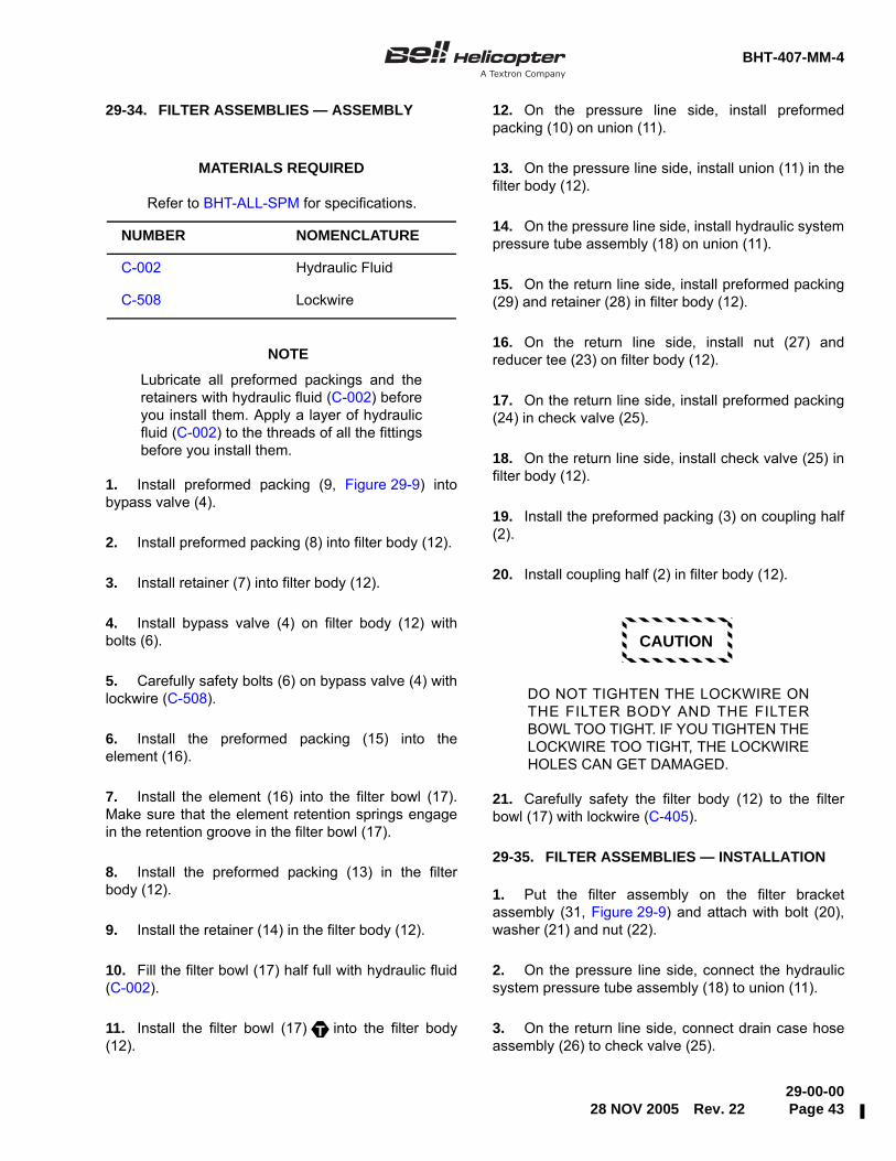
BHT-407-MM-4
29-00-0028 NOV 2005 Rev. 22 Page 43
29-34. FILTER ASSEMBLIES — ASSEMBLY
NOTE
Lubricate all preformed packings and theretainers with hydraulic fluid (C-002) beforeyou install them. Apply a layer of hydraulicfluid (C-002) to the threads of all the fittingsbefore you install them.
1. Install preformed packing (9, Figure 29-9) intobypass valve (4).
2. Install preformed packing (8) into filter body (12).
3. Install retainer (7) into filter body (12).
4. Install bypass valve (4) on filter body (12) withbolts (6).
5. Carefully safety bolts (6) on bypass valve (4) withlockwire (C-508).
6. Install the preformed packing (15) into theelement (16).
7. Install the element (16) into the filter bowl (17).Make sure that the element retention springs engagein the retention groove in the filter bowl (17).
8. Install the preformed packing (13) in the filterbody (12).
9. Install the retainer (14) in the filter body (12).
10. Fill the filter bowl (17) half full with hydraulic fluid(C-002).
11. Install the filter bowl (17) into the filter body(12).
12. On the pressure line side, install preformedpacking (10) on union (11).
13. On the pressure line side, install union (11) in thefilter body (12).
14. On the pressure line side, install hydraulic systempressure tube assembly (18) on union (11).
15. On the return line side, install preformed packing(29) and retainer (28) in filter body (12).
16. On the return line side, install nut (27) andreducer tee (23) on filter body (12).
17. On the return line side, install preformed packing(24) in check valve (25).
18. On the return line side, install check valve (25) infilter body (12).
19. Install the preformed packing (3) on coupling half(2).
20. Install coupling half (2) in filter body (12).
CAUTION
DO NOT TIGHTEN THE LOCKWIRE ONTHE FILTER BODY AND THE FILTERBOWL TOO TIGHT. IF YOU TIGHTEN THELOCKWIRE TOO TIGHT, THE LOCKWIREHOLES CAN GET DAMAGED.
21. Carefully safety the filter body (12) to the filterbowl (17) with lockwire (C-405).
29-35. FILTER ASSEMBLIES — INSTALLATION
1. Put the filter assembly on the filter bracketassembly (31, Figure 29-9) and attach with bolt (20),washer (21) and nut (22).
2. On the pressure line side, connect the hydraulicsystem pressure tube assembly (18) to union (11).
3. On the return line side, connect drain case hoseassembly (26) to check valve (25).
Refer to BHT-ALL-SPM for specifications.
MATERIALS REQUIRED
NUMBER NOMENCLATURE
C-002 Hydraulic Fluid
C-508 Lockwire
T

BHT-407-MM-4
29-00-00Page 44 Rev. 22 28 NOV 2005
4. On the return line side, connect hydraulic systemreturn tube assembly (30) to reducer tee (23).
5. Connect the coupling half (1) to the coupling half(2).
6. Fill the hydraulic system (Chapter 12).
7. Bleed the air from the hydraulic system(paragraph 29-10).
8. Install the transmission fairing (Chapter 53).
29-36. ELEMENT — DESCRIPTION
The element removes the particles from the hydraulicfluid. These particles come from the usual wear ofhydraulic components. The filtration rate is 590.6micro-inches (15 microns) absolute. The elementoperates at high pressure on a large temperaturerange. Examine, clean, or replace the element whenthe red indicator button extends and at therecommended inspection intervals (Chapter 5).
29-37. ELEMENT — REMOVAL
1. Remove the transmission fairing (Chapter 53).
2. Carefully cut and remove the lockwire from thefilter bowl (17, Figure 29-9) and from the filter body(12). Make sure that you do not damage the lockwireholes in the filter bowl (17) or in the filter body (12).
3. Remove the filter bowl (17), element (16),preformed packing (13) and the retainer (14). Discardthe preformed packing (13) and the retainer (14).
4. Remove the element (16) from the filter bowl (17).
5. Remove the preformed packing (15) from theelement (16). Discard the preformed packing (15).
29-38. ELEMENT — INSPECTION AND CLEANING
CAUTION
DO NOT USE ALCOHOL ON THEHYDRAULIC COMPONENTS. ALCOHOLCAN CAUSE DAMAGE TO THECOMPONENTS.
1. Examine the element (16, Figure 29-9) fordamage to the filtering surfaces, and bonding of theend caps to the filtering core and general condition.Replace the element if any abnormality is found.
2. Inspect the filtering core for metal, brass, andaluminum contamination. Replace the element ifcontamination is found and flush the hydraulic systemas per paragraph 29-3.
3. The filter element can be cleaned a maximum ofthree times with any one of the solutions that follows:
• Hydraulic fluid (C-002)
• Chlorothene (C-319) or equivalent
• Turbine fuel (C-003)
• Stoddard solvent (C-389)
• Half percent of cleaning compound (C-318) infiltered water. Backflush with water.
Refer to BHT-ALL-SPM for specifications.
MATERIALS REQUIRED
NUMBER NOMENCLATURE
C-002 Hydraulic Fluid
C-003 Turbine Fuel
C-318 Cleaning Compound
C-319 Chlorothene
C-389 Stoddard Solvent

BHT-407-MM-4
29-00-0016 FEB 2012 Rev. 34 Page 45ECCN EAR99
NOTE
Cap or plug both ends of element toprevent contaminant migration into theelement. Do not use ultrasonic equipment.
4. Submerge and vigorously agitate the element inone of the approved solvents.
5. Backflush the element with the same type ofsolvent used in step 4. Solvent/air mixture can beutilized. Backflush pressure to be 10 to 15 PSIG (69 to103 ΔkPa)
6. Repeat step 1. If the element is undamagedcontinue to step 7.
7. Dry the element with dry filtered air at 50 to 60PSI (345 to 414 kPa).
NOTE
Lubricate the preformed packing and theretainer with hydraulic fluid (C-002) beforeinstallation.
8. Replace the preformed packing (15).
9. Verify the retention spring on the filter element(16) for serviceability.
10. Scribe an X on the element bottom end toindicate each cleaning event.
29-39. ELEMENT — INSTALLATION
NOTE
Lubricate all the preformed packings andretainers with hydraulic fluid (C-002) before
you install them. Apply a layer of hydraulicfluid (C-002) to the threads of all the fittingsbefore you install them.
1. Install the preformed packing (15, Figure 29-9)into the element (16).
2. Install the element (16) into the filter bowl (17).Make sure that the element retention springs engagein the retention groove in the filter bowl (17).
3. Install the preformed packing (13) in the filterbody (12).
4. Install the retainer (14) in the filter body (12).
5. Fill the filter bowl (17) half full with hydraulic fluid(C-002).
6. Install the filter bowl (17) into the filter body (12).
CAUTION
DO NOT TIGHTEN THE LOCKWIRE ONTHE FILTER BODY AND THE FILTERBOWL TOO TIGHT. IF YOU TIGHTEN THELOCKWIRE TOO TIGHT, THE LOCKWIREHOLES CAN GET DAMAGED.
7. Carefully safety the filter bowl (17) and the filterbody (12) with lockwire (C-405).
8. Fill the hydraulic system (Chapter 12).
9. Bleed the air from the hydraulic system(paragraph 29-10).
10. Examine the red indicator button (5) during thebleed procedure. If the element (16) is not clean, thered indicator button will extend.
11. Check for leaks.
12. Install the transmission fairing (Chapter 53).
Refer to BHT-ALL-SPM for specifications.
MATERIALS REQUIRED
NUMBER NOMENCLATURE
C-002 Hydraulic Fluid
C-405 Lockwire
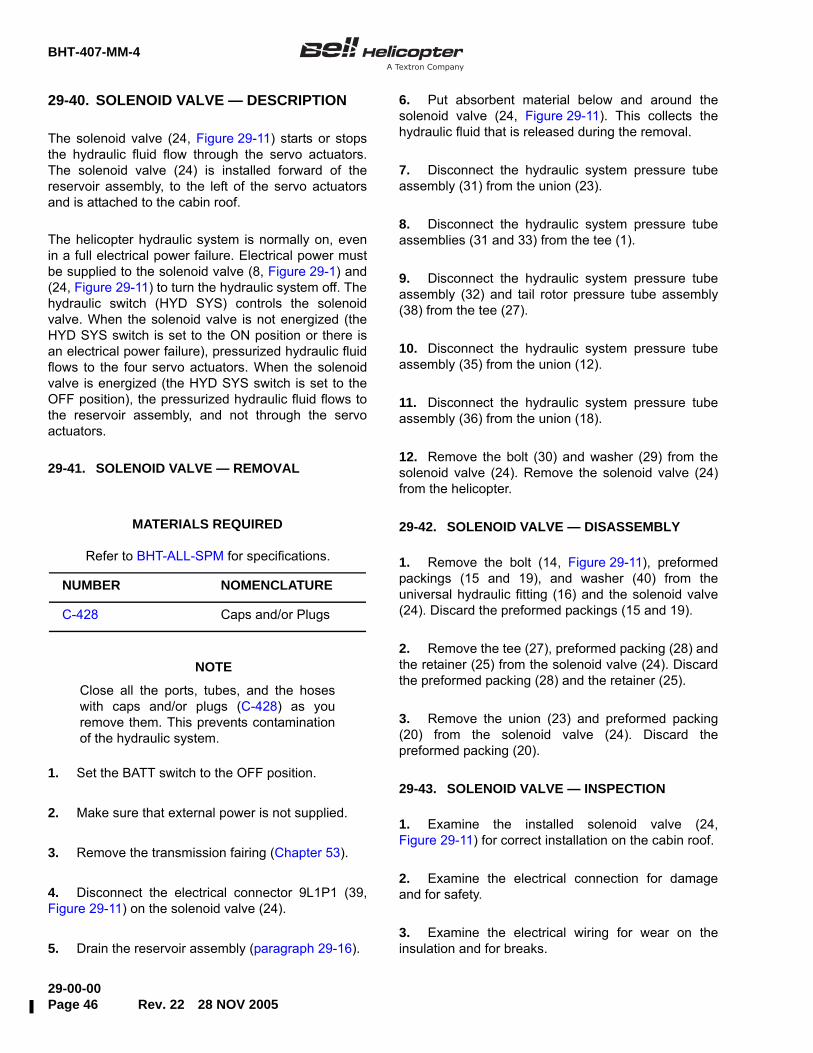
BHT-407-MM-4
29-00-00Page 46 Rev. 22 28 NOV 2005
29-40. SOLENOID VALVE — DESCRIPTION
The solenoid valve (24, Figure 29-11) starts or stopsthe hydraulic fluid flow through the servo actuators.The solenoid valve (24) is installed forward of thereservoir assembly, to the left of the servo actuatorsand is attached to the cabin roof.
The helicopter hydraulic system is normally on, evenin a full electrical power failure. Electrical power mustbe supplied to the solenoid valve (8, Figure 29-1) and(24, Figure 29-11) to turn the hydraulic system off. Thehydraulic switch (HYD SYS) controls the solenoidvalve. When the solenoid valve is not energized (theHYD SYS switch is set to the ON position or there isan electrical power failure), pressurized hydraulic fluidflows to the four servo actuators. When the solenoidvalve is energized (the HYD SYS switch is set to theOFF position), the pressurized hydraulic fluid flows tothe reservoir assembly, and not through the servoactuators.
29-41. SOLENOID VALVE — REMOVAL
NOTE
Close all the ports, tubes, and the hoseswith caps and/or plugs (C-428) as youremove them. This prevents contaminationof the hydraulic system.
1. Set the BATT switch to the OFF position.
2. Make sure that external power is not supplied.
3. Remove the transmission fairing (Chapter 53).
4. Disconnect the electrical connector 9L1P1 (39,Figure 29-11) on the solenoid valve (24).
5. Drain the reservoir assembly (paragraph 29-16).
6. Put absorbent material below and around thesolenoid valve (24, Figure 29-11). This collects thehydraulic fluid that is released during the removal.
7. Disconnect the hydraulic system pressure tubeassembly (31) from the union (23).
8. Disconnect the hydraulic system pressure tubeassemblies (31 and 33) from the tee (1).
9. Disconnect the hydraulic system pressure tubeassembly (32) and tail rotor pressure tube assembly(38) from the tee (27).
10. Disconnect the hydraulic system pressure tubeassembly (35) from the union (12).
11. Disconnect the hydraulic system pressure tubeassembly (36) from the union (18).
12. Remove the bolt (30) and washer (29) from thesolenoid valve (24). Remove the solenoid valve (24)from the helicopter.
29-42. SOLENOID VALVE — DISASSEMBLY
1. Remove the bolt (14, Figure 29-11), preformedpackings (15 and 19), and washer (40) from theuniversal hydraulic fitting (16) and the solenoid valve(24). Discard the preformed packings (15 and 19).
2. Remove the tee (27), preformed packing (28) andthe retainer (25) from the solenoid valve (24). Discardthe preformed packing (28) and the retainer (25).
3. Remove the union (23) and preformed packing(20) from the solenoid valve (24). Discard thepreformed packing (20).
29-43. SOLENOID VALVE — INSPECTION
1. Examine the installed solenoid valve (24,Figure 29-11) for correct installation on the cabin roof.
2. Examine the electrical connection for damageand for safety.
3. Examine the electrical wiring for wear on theinsulation and for breaks.
Refer to BHT-ALL-SPM for specifications.
MATERIALS REQUIRED
NUMBER NOMENCLATURE
C-428 Caps and/or Plugs

BHT-407-MM-4
29-00-0028 NOV 2005 Rev. 22 Page 47
Figure 29-11. Solenoid and Relief Valves
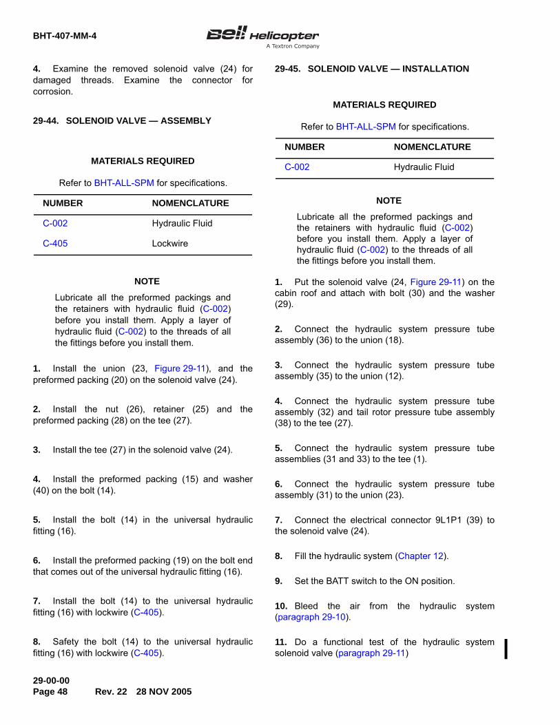
BHT-407-MM-4
29-00-00Page 48 Rev. 22 28 NOV 2005
4. Examine the removed solenoid valve (24) fordamaged threads. Examine the connector forcorrosion.
29-44. SOLENOID VALVE — ASSEMBLY
NOTE
Lubricate all the preformed packings andthe retainers with hydraulic fluid (C-002)before you install them. Apply a layer ofhydraulic fluid (C-002) to the threads of allthe fittings before you install them.
1. Install the union (23, Figure 29-11), and thepreformed packing (20) on the solenoid valve (24).
2. Install the nut (26), retainer (25) and thepreformed packing (28) on the tee (27).
3. Install the tee (27) in the solenoid valve (24).
4. Install the preformed packing (15) and washer(40) on the bolt (14).
5. Install the bolt (14) in the universal hydraulicfitting (16).
6. Install the preformed packing (19) on the bolt endthat comes out of the universal hydraulic fitting (16).
7. Install the bolt (14) to the universal hydraulicfitting (16) with lockwire (C-405).
8. Safety the bolt (14) to the universal hydraulicfitting (16) with lockwire (C-405).
29-45. SOLENOID VALVE — INSTALLATION
NOTE
Lubricate all the preformed packings andthe retainers with hydraulic fluid (C-002)before you install them. Apply a layer ofhydraulic fluid (C-002) to the threads of allthe fittings before you install them.
1. Put the solenoid valve (24, Figure 29-11) on thecabin roof and attach with bolt (30) and the washer(29).
2. Connect the hydraulic system pressure tubeassembly (36) to the union (18).
3. Connect the hydraulic system pressure tubeassembly (35) to the union (12).
4. Connect the hydraulic system pressure tubeassembly (32) and tail rotor pressure tube assembly(38) to the tee (27).
5. Connect the hydraulic system pressure tubeassemblies (31 and 33) to the tee (1).
6. Connect the hydraulic system pressure tubeassembly (31) to the union (23).
7. Connect the electrical connector 9L1P1 (39) tothe solenoid valve (24).
8. Fill the hydraulic system (Chapter 12).
9. Set the BATT switch to the ON position.
10. Bleed the air from the hydraulic system(paragraph 29-10).
11. Do a functional test of the hydraulic systemsolenoid valve (paragraph 29-11)
Refer to BHT-ALL-SPM for specifications.
MATERIALS REQUIRED
NUMBER NOMENCLATURE
C-002 Hydraulic Fluid
C-405 Lockwire
Refer to BHT-ALL-SPM for specifications.
MATERIALS REQUIRED
NUMBER NOMENCLATURE
C-002 Hydraulic Fluid
BHT-407-MM-4
29-00-0028 NOV 2005 Rev. 22 Page 49
12. Install the transmission fairing (Chapter 53).
29-46. HYDRAULIC FLIGHT CONTROLRELIEF VALVE — DESCRIPTION
The hydraulic flight control relief valve (5,Figure 29-11) is installed forward of the reservoir andis connected to the solenoid valve (24). The hydraulicflight control relief valve (5) is normally closed. If thesystem pressure increases to 1225 ± 150 PSI (8446 ±1034 kPa), the hydraulic flight control relief valve (5)opens and sends the pressure back to the reservoir.The hydraulic flight control relief valve (5) protects thehydraulic system from high pressure damage.
29-47. HYDRAULIC FLIGHT CONTROL RELIEFVALVE — REMOVAL
NOTE
Close all the ports, tubes, and the hoseswith caps and/or plugs (C-428) as youremove them. This prevents contaminationof the hydraulic system.
1. Remove the transmission fairing (Chapter 53).
2. Drain the reservoir assembly (paragraph 29-16).
3. Put absorbent material below and around thehydraulic flight control relief valve (5, Figure 29-11).This collects the hydraulic fluid released during theremoval procedure.
4. Disconnect the hydraulic system pressure tubeassemblies (31 and 33) from the tee (1).
5. Disconnect the hydraulic flight control relief valve(5) from the elbow (7). Discard the preformed packing(37).
6. Remove the union (2) and preformed packing (6)from the hydraulic flight control relief valve (5). Discardthe preformed packing (6).
7. Remove the tee (1), preformed packing (4) andthe retainer (3) from the hydraulic flight control reliefvalve (5). Discard the preformed packing (4) and theretainer (3).
29-48. HYDRAULIC FLIGHT CONTROL RELIEFVALVE — INSPECTION
The operation of the hydraulic flight control relief valveis tested with the hydraulic test stand (paragraph29-11).
1. Examine the installed hydraulic flight control reliefvalve (5, Figure 29-11) for damage, leakage andsafety.
2. Examine the removed hydraulic flight controlrelief valve (5) for damage to the threads in the portsand for corrosion.
29-49. HYDRAULIC FLIGHT CONTROL RELIEFVALVE — INSTALLATION
NOTE
Lubricate all the preformed packings andthe retainers with hydraulic fluid (C-002)before you install them. Apply a layer ofhydraulic fluid (C-002) to the threads of allthe fittings before you install them.
1. Install the preformed packing (6, Figure 29-11) onthe union (2).
2. Install the union (2) in the hydraulic flight controlrelief valve (5), at the end that is marked RET.
3. Install the preformed packing (37) on the union(2).
Refer to BHT-ALL-SPM for specifications.
MATERIALS REQUIRED
NUMBER NOMENCLATURE
C-428 Caps and/or Plugs
Refer to BHT-ALL-SPM for specifications.
MATERIALS REQUIRED
NUMBER NOMENCLATURE
C-002 Hydraulic Fluid
BHT-407-MM-4
29-00-00Page 50 Rev. 22 28 NOV 2005
4. Install the union (2) with the hydraulic flightcontrol relief valve (5) in the elbow (7).
5. Install a new retainer (3) and the preformedpacking (4) on the tee (1).
6. Install the tee (1) in the end of the hydraulic flightcontrol relief valve (5) marked PRESS.
7. Connect the hydraulic system pressure tubeassembly (31) to the inboard tee (1).
8. Connect the hydraulic system pressure tubeassembly (33) to the aft end of the tee (1).
9. Fill the hydraulic system (Chapter 12).
10. Bleed the hydraulic system (paragraph 29-10).
11. Do a functional test of the hydraulic flight controlrelief valve (5) (paragraph 29-11).
12. Install the transmission fairing (Chapter 53).
29-50. RETURN AND PRESSURE COUPLINGHALVES — DESCRIPTION
The return and pressure coupling halves (3 and 4,Figure 29-1) are installed in the hydraulic system.These couplings make it easier for you to do themaintenance tasks and tests. The return and pressurecoupling halves are different sizes: the smaller one (4)is on the pressure line and the larger one (3) is on thereturn line. The different sizes prevent the mix up ofthe pressure line and the return line during themaintenance tasks and tests. The return and pressurecoupling halves are made up of two coupling halves (1and 2, Figure 29-9). When the coupling halves aredisconnected, the coupling half openingsautomatically close. This prevents contamination ofthe hydraulic system and fluid leakage.
29-51. RETURN AND PRESSURE COUPLINGHALVES — REMOVAL
CAUTION
CLOSE ALL THE PORTS, TUBES ANDHOSES WITH CAPS AND/OR PLUGS(C-428) AS YOU REMOVE THEM. THISWILL PREVENT CONTAMINATION OFUNWANTED MATERIALS INTO THEHYDRAULIC SYSTEM.
1. Remove the transmission fairing (Chapter 53).
2. Put a container below the coupling half (1) andcoupling half (2), to catch the hydraulic fluid that isreleased when the coupling half (1) is disconnected.
3. Hold the coupling half (1, Figure 29-9) of thequick-disconnect and push in the direction of the filterassembly. Turn the coupling half (1) counterclockwiseand disconnect from the coupling half (2).
4. Remove the coupling half (1) from the hoseassembly (19).
5. Remove the coupling half (2) and preformedpacking (3) from the filter body (12). Discard thepreformed packing (3).
29-52. RETURN AND PRESSURE COUPLINGHALVES — INSPECTION
1. Examine the coupling half (1, Figure 29-9) andthe coupling half (2) for cracks, distortion, and correctlocking operation when the coupling halves are joined.Special tools and preformed packings are required forthe coupling halves. These are available from thecoupling half manufacturer.
Refer to BHT-ALL-SPM for specifications.
MATERIALS REQUIRED
NUMBER NOMENCLATURE
C-428 Caps and/or Plugs
BHT-407-MM-4
29-00-0028 NOV 2005 Rev. 22 Page 51
29-53. RETURN AND PRESSURE COUPLINGHALVES — INSTALLATION
NOTE
Lubricate all the preformed packings andthe retainers with hydraulic fluid (C-002)before you install them. Apply a layer ofhydraulic fluid (C-002) to the threads of allthe fittings before you install them.
1. Install the preformed packing (3, Figure 29-9) onthe coupling half (2).
2. Install the coupling half (2) in the filter body (12).
3. Install the coupling half (1) in the hose assembly(19).
4. Connect the coupling half (1) to the coupling half(2).
5. Fill the hydraulic system (Chapter 12).
6. Bleed the hydraulic system (paragraph 29-10).
7. Inspect for leaks.
8. Install the transmission fairing (Chapter 53).
29-54. HYDRAULIC PRESSURE SWITCH —DESCRIPTION
Refer to Chapter 96 for the description and operationand the removal and installation procedures of thehydraulic pressure switch.
29-55. HYDRAULIC PRESSURE SWITCH —INSPECTION
1. Examine the hydraulic pressure switch fordamage, pitting, and corrosion.
2. Examine the electrical receptacle of the hydraulicpressure switch for damage and corrosion.
3. Examine the threads of the hydraulic pressureswitch for damage.
29-56. HYDRAULIC SYSTEM MANIFOLD —DESCRIPTION
The hydraulic system manifold (1, Figure 29-12) isinstalled on the forward end of the actuator support(17, Figure 29-1). The hydraulic system manifold (1,Figure 29-12) is divided into two sides: a pressure sideand a return side. Hydraulic fluid that goes from thehydraulic pump (10, Figure 29-1) to the servoactuators passes through the pressure side of thehydraulic system manifold. The pressure side of thehydraulic system manifold has a pressure switch inone end. Hydraulic fluid that goes from the servoactuators to the reservoir assembly passes throughthe return side of the hydraulic system manifold.
29-57. HYDRAULIC SYSTEM MANIFOLD —REMOVAL
CAUTION
CLOSE ALL THE PORTS, TUBES ANDHOSES WITH CAPS AND/OR PLUGS(C-428) AS YOU REMOVE THEM. THISWILL PREVENT CONTAMINATION OFUNWANTED MATERIALS INTO THEHYDRAULIC SYSTEM.
1. Remove the transmission fairing (Chapter 53).
2. Drain the reservoir assembly (paragraph 29-16).
Refer to BHT-ALL-SPM for specifications.
MATERIALS REQUIRED
NUMBER NOMENCLATURE
C-002 Hydraulic Fluid
Refer to BHT-ALL-SPM for specifications.
MATERIALS REQUIRED
NUMBER NOMENCLATURE
C-428 Caps and/or Plugs

BHT-407-MM-4
29-00-00Page 52 Rev. 22 28 NOV 2005
Figure 29-12. Hydraulic System Manifold — Maintenance Practices

BHT-407-MM-4
29-00-0028 NOV 2005 Rev. 22 Page 53
3. Put a container below the hydraulic systemmanifold (1, Figure 29-12) to catch the hydraulic fluidthat is released from the hydraulic system manifold (1)when the hoses are disconnected.
4. Disconnect the three return hose assemblies (4)from the three elbows (3).
5. Disconnect the three pressure hose assemblies(7) from the two unions (6) and the tee (13).
6. Disconnect the hydraulic system pressure tubeassembly (14) from the tee (13).
7. Disconnect the hydraulic system return tubeassembly (18) from the elbow (17).
8. Remove the bolt (19), washers (20) and the nut(21). Remove the hydraulic system manifold (1) fromthe helicopter.
29-58. HYDRAULIC SYSTEM MANIFOLD —DISASSEMBLY
1. Remove the three elbows (3, Figure 29-12),retainers (27) and preformed packings (2) from thereturn side of the hydraulic system manifold (1).Discard the retainers (27) and the preformed packings(2).
2. Remove the two unions (6) and preformedpackings (5) from the pressure side of the hydraulicsystem manifold (1). Discard the preformed packings(5).
3. Remove the tee (13), preformed packing (10) andthe retainer (11) from the pressure side of thehydraulic system manifold (1). Discard the preformedpacking (10) and the retainer (11).
4. Remove the hydraulic pressure switch (Chapter96).
5. Loosen the nut (9) on the tee (22) and remove thetee (22), retainer (24) and the preformed packing (8)from the hydraulic system manifold (1). Discard theretainer (27) and the preformed packing (8).
6. Remove the elbow (17), retainer (25) andpreformed packing (15) from the return side of thehydraulic system manifold (1). Discard the retainer(25) and the preformed packing (15).
29-59. HYDRAULIC SYSTEM MANIFOLD —INSPECTION
1. Examine the hydraulic system manifold (1,Figure 29-12) for cracks, wear and other damage.
2. Refer to BHT-ALL-SPM for the repair of smallsurface scratches that get into the aluminum alloy.
3. Examine all of the hydraulic system manifoldports for damage to the threads.
4. Examine all of the fittings for damage.
29-60. HYDRAULIC SYSTEM MANIFOLD —ASSEMBLY
NOTE
Lubricate all the preformed packings andretainers with hydraulic fluid (C-002) beforeyou install them. Apply a layer of hydraulicfluid (C-002) to the threads of all the fittingsbefore you install them.
1. Install the nut (16, Figure 29-12), retainer (25)and the preformed packing (15) on the elbow (17).
2. Install the elbow (17) in the return side of thehydraulic system manifold (1).
3. Install the nut (9), retainer (24) and the preformedpacking (8) on the tee (22).
4. Install the tee (22) on the pressure side of thehydraulic system manifold (1). Tighten the nut (9).
5. Install the hydraulic pressure switch (23) (Chapter96).
6. Install the nut (12), retainer (11) and thepreformed packing (10) on the tee (13).
Refer to BHT-ALL-SPM for specifications.
MATERIALS REQUIRED
NUMBER NOMENCLATURE
C-002 Hydraulic Fluid

BHT-407-MM-4
29-00-00Page 54 Rev. 22 28 NOV 2005
7. Install the tee (13) in the pressure side of thehydraulic system manifold (1).
8. Install the preformed packings (5) on the twounions (6).
9. Install the two unions (6) in the pressure side ofthe hydraulic system manifold (1).
10. Install the nuts (26), retainers (27) and thepreformed packings (2) on the three elbows (3).
11. Install the three elbows (3) on the return side ofthe hydraulic system manifold (1).
29-61. HYDRAULIC SYSTEM MANIFOLD —INSTALLATION
1. Put the hydraulic system manifold (1,Figure 29-12) in the correct location on the actuatorsupport (17, Figure 29-1) and attach with the bolt (19,Figure 29-12), washers (20) and the nut (21).
2. Connect the hydraulic system return tubeassembly (18) to the elbow (17).
3. Connect the hydraulic system pressure tubeassembly (14) to the horizontal fitting of the tee (13).
4. Connect the three pressure hose assemblies (7)to the two unions (6) and the vertical fitting of the tee(13).
5. Connect the three return hose assemblies (4) tothe three elbows (3).
6. Connect the electrical connector to the hydraulicpressure switch (23). (Chapter 96).
7. Fill the hydraulic system (Chapter 12).
8. Bleed the hydraulic system (paragraph 29-10).
9. Install the transmission fairing (Chapter 53).
29-62. HYDRAULIC HOSES AND TUBEASSEMBLIES — DESCRIPTION
The hydraulic hoses and tube assemblies(Figure 29-12) connect the components of thehydraulic system. The tube assemblies have sleeve
end fittings that are kept on the tubes by the flaredends of the tubes.
29-63. HYDRAULIC HOSES AND TUBEASSEMBLIES — REMOVAL
CAUTION
CLOSE ALL THE PORTS, TUBES ANDHOSES WITH CAPS AND/OR PLUGS(C-428) AS YOU REMOVE THEM. THISWILL PREVENT CONTAMINATION OFUNWANTED MATERIALS INTO THEHYDRAULIC SYSTEM.
1. Remove the transmission fairing (Chapter 53).
2. Disconnect the hose or the tube assembly fromthe end fittings.
3. Remove the clamps from the hose or the tubeassembly.
4. Remove the hose or the tube assembly.
29-64. HYDRAULIC HOSES AND TUBEASSEMBLIES — INSPECTION ANDCLEANING
1. Examine the hose or tube assembly for wear,crimps, leakage and damage to the fittings.
Refer to BHT-ALL-SPM for specifications.
MATERIALS REQUIRED
NUMBER NOMENCLATURE
C-428 Caps and/or Plugs
Refer to BHT-ALL-SPM for specifications.
MATERIALS REQUIRED
NUMBER NOMENCLATURE
C-304 Drycleaning Solvent

BHT-407-MM-4
29-00-0016 FEB 2012 Rev. 34 Page 55ECCN EAR99
2. Clean the hose or tube assembly withdrycleaning solvent (C-304) before you install it.
29-65. HYDRAULIC HOSES AND TUBEASSEMBLIES — INSTALLATION
NOTE
To install the hoses, start the nut by handand use a backup wrench on the hosefitting to stop twists in the hose.
1. Put the hose or tube assembly in place andconnect to the end fittings.
2. Install the clamps and supports.
3. Make sure that the hose or the tube assemblydoes not touch other components.
4. Fill the hydraulic system (Chapter 12).
5. Bleed the hydraulic system (paragraph 29-10).
6. During the bleeding procedure examine the hoseand tube assemblies for leaks and ensure that chaffingwill not occur as the controls are moved. If notedclearance of hoses to other items is not sufficient toeliminate any possibility of chaffing, reposition hosesas required to eliminate condition.
7. Install the transmission fairing (Chapter 53).
29-66. SERVO ACTUATORS — 12-MONTHINSPECTION
NOTE
The following procedure consists of aninspection of each servo actuator clevisassembly (3, Figure 29-13) for security.
1. For the cyclic and collective servo actuators,remove the transmission fairing assembly(Chapter 53).
2. For the directional control servo actuator, removethe upper access cover in the baggage compartment.
3. Retract the boot (2).
4. Applying hand pressure only, make sure that theshaft (5), clevis assembly (3), and nut (1) are tight andall rotate as a unit. Any rotational looseness betweenthe parts is not allowed.
NOTE
Refer to General Information Letter (IL)GEN-04-98 for the applicable shippinginformation and to obtain a Return MaterialAuthorization (RMA) number.
5. If any rotational looseness is identified betweenthe shaft (5), clevis assembly (3), or nut (1), return thepart to Bell Helicopter Textron (BHT) for evaluationand possible repair.
6. Make sure a minimum of one tab of thelockwasher (4) is bent flush with one flat surface of thenut (1) and a minimum of one tab of the lockwasher isbent flush with one flat surface of the clevisassembly (3).
7. If a tab of the lockwasher (4) is not bent correctly,bend it flush with the mating flat surface on the nut (1)or the clevis assembly (3), as applicable, with pliers.
NOTE
Refer to General Information Letter (IL)GEN-04-98 for the applicable shippinginformation and to obtain a Return MaterialAuthorization (RMA) number.
8. If no tab of the lockwasher (4) is aligned with theflat surfaces of the nut (1) and the clevis assembly (3),return the part to BHT for evaluation and possiblerepair.
9. Apply torque seal (C-049) to the parts if brokenduring the inspection.
10. Put the boot (2) back in position.
Refer to BHT-ALL-SPM for specifications.
MATERIALS REQUIRED
NUMBER NOMENCLATURE
C-049 Torque Seal

BHT-407-MM-4
29-00-00Page 56 Rev. 35 10 DEC 2012 Export Classification C, ECCN EAR99
Figure 29-13. Servo Actuators — 12-Month Inspection407_MM_29_0019_c01
1.2.3.4.5.
NutBootClevis assemblyLockwasherShaft
DETAIL A(TYPICAL 4 PLACES)
2
3
TAB5
1
4
SEE DETAIL A
SEE DETAIL A
BHT-407-MM-4
29-00-0010 DEC 2012 Rev. 35 Page 57Export Classification C, ECCN EAR99
11. Do this inspection again for the remaining servoactuators.
12. For the directional control servo actuator, installthe upper access cover in the baggage compartment.
13. For the cyclic and collective servo actuators,install the transmission fairing assembly (Chapter 53).
29-67. SERVO ACTUATORS — 24-MONTHINSPECTION
CAUTION
USE ONLY HAND PRESSURE TO DOTHE FOLLOWING PROCEDURE ORDAMAGE TO THE SERVO ACTUATORSMAY OCCUR.
NOTE
During this procedure, the servo actuatorswill not move easily because they areconnected to the upper controls.
1. For each servo actuator (1, Figure 29-14) of thecyclic and collective controls, do as follows:
a. On the overhead console, make sure theOFF/HYD SYS switch (4A2S2) is set to the OFFposition.
b. Remove the transmission fairing assembly(Chapter 53).
c. Disconnect the input control tubes from thelateral, longitudinal, and collective boost bellcranks, asapplicable (Chapter 67).
d. Install a dial indicator on the servo actuator (1)so the tip touches the clevis assembly (2), as shown inFigure 29-14.
NOTE
The first stops of the bypass spool valve, inthe extended and retracted position, arespring preloaded.
e. Measure the distance between the two firststops of the bypass spool valve as follows:
(1) Push or pull on the bellcrank assembly(3) to move the bypass spool valve to the extended orretracted position, until it reaches the first stop.
(2) Set the dial indicator to zero.
(3) Push or pull the bellcrank assembly (3) tomove the bypass spool valve to the opposite position,until it reaches the first stop.
(4) On the dial indicator, measure and recordthe range of travel of the bypass spool valve.
NOTE
Refer to General Information Letter (IL)GEN-04-98 for the applicable shippinginformation and to obtain a Return MaterialAuthorization (RMA) number.
(5) If the range of travel is not 0.018 to0.022 inch (0.46 to 0.56 mm), return the part to BellHelicopter Textron (BHT) for evaluation and possiblerepair.
NOTE
The first stop of the bypass spool valve, inthe extended or retracted position, is springpreloaded and the second is mechanical.
f. Measure the distance between the first stopand the second stop of the bypass spool valve asfollows:
(1) Push or pull on the bellcrank assembly(3) to move the bypass spool valve to the extended orretracted position, until it reaches the first stop.
(2) Set the dial indicator to zero.
(3) Increase hand pressure on the bellcrankassembly (3) sufficiently to move the bypass spoolvalve in the same direction, until it reaches the secondstop.
SPECIAL TOOLS REQUIRED
NUMBER NOMENCLATURE
Commercial Dial Indicator
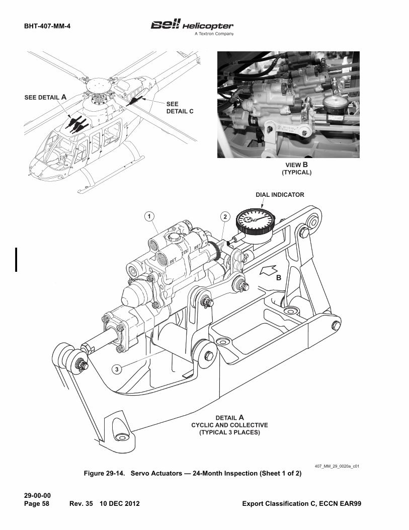
BHT-407-MM-4
29-00-00Page 58 Rev. 35 10 DEC 2012 Export Classification C, ECCN EAR99
Figure 29-14. Servo Actuators — 24-Month Inspection (Sheet 1 of 2)407_MM_29_0020a_c01
DETAIL ACYCLIC AND COLLECTIVE
(TYPICAL 3 PLACES)
VIEW B(TYPICAL)
1 2
SEE DETAIL A
DIAL INDICATOR
SEEDETAIL C
B
3

BHT-407-MM-4
29-00-0010 DEC 2012 Rev. 35 Page 59Export Classification C, ECCN EAR99
Figure 29-14. Servo Actuators — 24-Month Inspection (Sheet 2 of 2)
DIAL INDICATOR
407_MM_29_0020b_c01
1.2.3.4.5.6.7.8.
Servo actuatorClevis assemblyBellcrank assemblyServo actuatorDirectional control tubeIdler assemblyLink assemblyClevis assembly
DETAIL CDIRECTIONAL CONTROL
5
4 8
6
7

BHT-407-MM-4
29-00-00Page 60 Rev. 35 10 DEC 2012 Export Classification C, ECCN EAR99
(4) Make sure the bypass spool valve hasfull freedom of travel and operation without sign ofsticking or slow operation.
(5) On the dial indicator, measure and recordthe range of stroke of the bypass spool valve.
NOTE
Refer to IL GEN-04-98 for the applicableshipping information and to obtain a RMAnumber.
(6) If the range of stroke is not 0.008 to0.019 inch (0.20 to 0.48 mm), return the part to BHTfor evaluation and possible repair.
(7) Do step (1) through step (6) again for theopposite position.
g. Do step a through step f again for theremaining servo actuators (1).
h. Remove the dial indicator from the servoactuator (1).
i. Connect the control tubes to the lateral,longitudinal, and collective boost bellcranks, asapplicable (Chapter 67).
j. Install the transmission fairing assembly(Chapter 53).
CAUTION
USE ONLY HAND PRESSURE TO DOTHE FOLLOWING PROCEDURE ORDAMAGE TO THE SERVO ACTUATORSMAY OCCUR.
NOTE
During this procedure, the servo actuatorwill not move easily because it is connectedto the rear control.
2. For the servo actuator (4) of the directionalcontrol, do as follows:
a. On the overhead console, make sure theOFF/HYD SYS switch (4A2S2) is set to the OFFposition.
b. In the baggage compartment, remove theupper access cover.
c. Disconnect the directional control tube (5)from the idler assembly (6) (Chapter 67).
d. Connect the link assemblies (7) to the idlerassembly (6) (Chapter 67).
e. Install a dial indicator on the servo actuator (4)so the tip touches the clevis assembly (8), as shown inFigure 29-14.
NOTE
The first stops of the bypass spool valve, inthe extended and retracted position, arespring preloaded.
f. Measure the distance between the two firststops of the bypass spool valve as follows:
(1) Push or pull on the idler assembly (6) tomove the bypass spool valve to the extended orretracted position, until it reaches the first stop.
(2) Set the dial indicator to zero.
(3) Push or pull on the idler assembly (6) tomove the bypass spool valve to the opposite position,until it reaches the first stop.
(4) On the dial indicator, measure and recordthe range of travel of the bypass spool valve.
NOTE
Refer to IL GEN-04-98 for the applicableshipping information and to obtain a RMAnumber.
(5) If the range of travel is not 0.030 to0.035 inch (0.77 to 0.88 mm), return the part to BHTfor evaluation and possible repair.
NOTE
The first stop of the bypass spool valve, inthe extended or retracted position, is springpreloaded and the second is mechanical.
g. Measure the distance between the first stopand the second stop of the bypass spool valve asfollows:
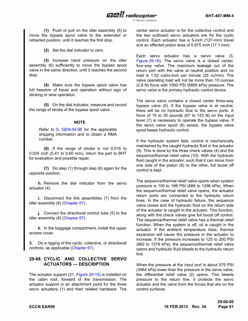
BHT-407-MM-4
29-00-0016 FEB 2012 Rev. 34 Page 61ECCN EAR99
(1) Push or pull on the idler assembly (6) tomove the bypass spool valve to the extended orretracted position, until it reaches the first stop.
(2) Set the dial indicator to zero.
(3) Increase hand pressure on the idlerassembly (6) sufficiently to move the bypass spoolvalve in the same direction, until it reaches the secondstop.
(4) Make sure the bypass spool valve hasfull freedom of travel and operation without sign ofsticking or slow operation.
(5) On the dial indicator, measure and recordthe range of stroke of the bypass spool valve.
NOTE
Refer to IL GEN-04-98 for the applicableshipping information and to obtain a RMAnumber.
(6) If the range of stroke is not 0.016 to0.024 inch (0.41 to 0.60 mm), return the part to BHTfor evaluation and possible repair.
(7) Do step (1) through step (6) again for theopposite position.
h. Remove the dial indicator from the servoactuator (4).
i. Disconnect the link assemblies (7) from theidler assembly (6) (Chapter 67).
j. Connect the directional control tube (5) to theidler assembly (6) (Chapter 67).
k. In the baggage compartment, install the upperaccess cover.
3. Do a rigging of the cyclic, collective, or directionalcontrols, as applicable (Chapter 67).
29-68. CYCLIC AND COLLECTIVE SERVOACTUATORS — DESCRIPTION
The actuator support (21, Figure 29-15) is installed onthe cabin roof, forward of the transmission. Theactuator support is an attachment point for the threeservo actuators (1) and their related hardware. The
center servo actuator is for the collective control andthe two outboard servo actuators are for the cycliccontrol. Each actuator has a 5-inch (127-mm) traveland an effected piston area of 0.675 inch (17.1 mm).
Each servo actuator has a servo valve (3,Figure 29-16). The servo valve is a closed center,four-way valve. The maximum leakage out of thereturn port with the valve at neutral position and noload is 1.52 cubic-inch per minute (25 cc/min). Thevalve operating load will not be more than 10 ounces(2.8 N) force with 1000 PSI (6895 kPa) pressure. Theservo valve is the primary hydraulic control device.
The servo valve contains a closed center three-waybypass valve (5). If the bypass valve is at neutral,there will be no hydraulic flow to the servo ports. Aforce of 15 to 30 pounds (67 to 133 N) on the inputlever (7) is necessary to operate the bypass valve. Ifthe servo valve spool (6) seizes, the bypass valvespool keeps hydraulic control.
If the hydraulic system fails, control is mechanicallymaintained by the caught hydraulic fluid in the actuator(9). This is done by the three check valves (4) and thesequence/thermal relief valve (10). With the hydraulicfluid caught in the actuator, such that it can move fromone side of the piston (8) to the other, full boost offcontrol is kept.
The sequence/thermal relief valve opens when systempressure is 100 to 188 PSI (689 to 1296 kPa). Whenthe sequence/thermal relief valve opens, the actuatorreturn ports are connected to the hydraulic returnlines. In the case of hydraulic failure, the sequencevalve closes and the hydraulic fluid on the return sideof the actuator is caught in the actuator. This function,along with the check valves give full boost off control.The sequence/thermal relief valve has a thermal relieffunction. When the system is off, oil is caught in theactuator. If the ambient temperature rises, thermalexpansion will cause the pressure in the actuator toincrease. If the pressure increases to 125 to 200 PSI(862 to 1379 kPa), the sequence/thermal relief valveopens and hydraulic fluid bleeds to the hydraulic returnline.
When the pressure at the input port is about 575 PSI(3964 kPa) lower than the pressure in the servo valve,the differential relief valve (2) opens. This bleedspressure to the return line. It protects the servoactuator and the valve from the forces that are on thecontrol surfaces.

BHT-407-MM-4
29-00-00Page 62 Rev. 34 16 FEB 2012 ECCN EAR99
Figure 29-15. Cyclic and Collective Servo Actuators and Bellcranks — Maintenance Practices(Sheet 1 of 2)
NO OBJECT BEYOND THIS POINT 407MM_29_0015_c01
21
16
1718
29
2019
2511
12
13
15
10
98
87
6
2223
24
1
34
28
2 527
26
1415 12
11
13
130
1
2
1
SEE DETAIL A
2

BHT-407-MM-4
29-00-0016 FEB 2012 Rev. 34 Page 63ECCN EAR99
Figure 29-15. Cyclic and Collective Servo Actuators and Bellcranks — Maintenance Practices(Sheet 2 of 2)
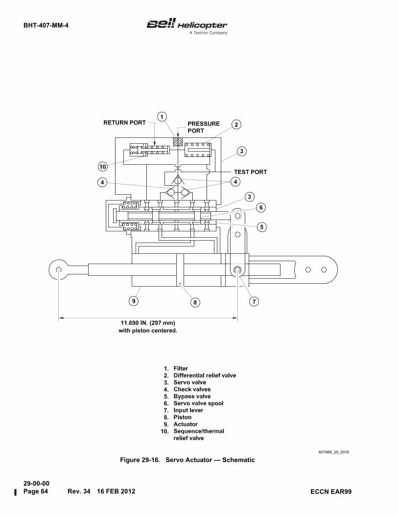
BHT-407-MM-4
29-00-00Page 64 Rev. 34 16 FEB 2012 ECCN EAR99
Figure 29-16. Servo Actuator — Schematic

BHT-407-MM-4
29-00-0016 FEB 2012 Rev. 34 Page 65ECCN EAR99
The inlet (pressure) port of the servo valve has a 150micron absolute filter (1). This filter is not replaceable.
29-69. CYCLIC AND COLLECTIVE SERVOACTUATORS — REMOVAL
CAUTION
CLOSE ALL THE PORTS, TUBES, ANDHOSES WITH CAPS AND/OR PLUGS(C-428) AS YOU REMOVE THEM. THISWILL PREVENT CONTAMINATION OFUNWANTED MATERIALS INTO THEHYDRAULIC SYSTEM.
NOTE
The removal procedures for the cyclic andcollective servo actuators (1, Figure 29-15)are almost the same. Use this procedure toremove all three servo actuators (1).
1. Remove the transmission fairing (Chapter 53).
2. Drain the reservoir assembly (paragraph 29-16).
3. Put a clean rag on the servo actuator (1) belowthe pressure and return hose assemblies (2 and 3) tocatch the hydraulic fluid that is released when youdisconnect the pressure and return hose assemblies.
4. Disconnect the return hose assembly (3) from theunion (4).
5. Disconnect the pressure hose assembly (2) fromthe union (5).
6. Remove the cotter pin (6), nut (7), washers (8),and bolt (9) from the aft end of the servo actuator (1).Disconnect the aft end of the servo actuator from theidler assembly (10).
7. Remove the cotter pin (11), nut (12), and safetybearing washer (13) from the studs on two sides of theservo actuator trunnion (14).
8. Remove the two link assemblies (15) from theservo actuator trunnion (14).
9. Remove the cotter pin (16), nut (17), washers (18and 20), and bolt (19) from the servo actuator rod end(24). Remove the servo actuator (1) from thesupport (21).
10. Remove the slip bushing (29) from the actuatorsupport (21).
29-70. CYCLIC AND COLLECTIVE SERVOACTUATORS — INSPECTION ANDCLEANING
Do not repair the servo actuators. If the servo actuatorhas damage, replace the servo actuator. Send thedamaged servo actuator to the manufacturer or to anapproved overhaul facility for repair or overhaul.
CAUTION
DO NOT USE ALCOHOL ON THEHYDRAULIC COMPONENTS. ALCOHOLCAN CAUSE DAMAGE TO THECOMPONENTS.
DO NOT PUT CLAMPS ON THECYLINDER OF THE SERVO ACTUATOR.DO NOT PUT THE CYLINDER IN A VICE.DOING SO CAN CAUSE DAMAGE TOTHE CYLINDER.
Refer to BHT-ALL-SPM for specifications.
MATERIALS REQUIRED
NUMBER NOMENCLATURE
C-428 Caps and/or Plugs
Refer to BHT-ALL-SPM for specifications.
MATERIALS REQUIRED
NUMBER NOMENCLATURE
C-107 Hydraulic Fluid Preservative
C-304 Drycleaning Solvent

BHT-407-MM-4
29-00-00Page 66 Rev. 34 16 FEB 2012 ECCN EAR99
1. Clean the servo actuator (1, Figure 29-15) withdrycleaning solvent (C-304). Use a non-metallic bristlebrush to remove stubborn dirt.
2. Use compressed filtered air to dry the servoactuator (1).
3. Apply a thin layer of hydraulic fluid preservative(C-107) to all the metal surfaces.
4. Clean the servo actuator support (21) withdrycleaning solvent (C-304). Make sure that you donot get the drycleaning solvent on the adjacentactuator rods, bearings, or seals.
5. Clean the pressure and return hose assemblies(2 and 3) with drycleaning solvent (C-304)
6. Examine the servo actuator (1) for cracks,corrosion, and other damage.
7. Examine all the threaded parts and the ports fordamaged threads and cracks.
8. Examine the hoses and the fittings for leaks andwear. Make sure that they are attached correctly.
29-71. CYCLIC AND COLLECTIVE SERVOACTUATORS — INSTALLATION
CAUTION
DO NOT PUT CLAMPS ON THECYLINDER OF THE SERVO ACTUATOR.DO NOT PUT THE CYLINDER IN A VICE.DOING SO CAN CAUSE DAMAGE TOTHE CYLINDER.
NOTE
The installation procedure for the cyclic andthe collective servo actuators is almost thesame. Use this procedure to install all threeservo actuators.
NOTE
Apply a coating of corrosion preventivecompound (C-104) to all bolt shanks priorto installation. Do not apply corrosionpreventive compound to the bolt threads.
1. When a new or overhauled cyclic and collectiveservo actuator is to be installed, accomplish thefollowing adjustment prior to installation.
a. Set the servo actuator piston to its midstrokeposition. Set the servo valve in neutral with the aid ofthe servo actuator rigging tool (T102019).
b. Adjust the servo-actuator rod end bearing (24,Figure 29-15) to obtain an overall dimension of 11.690±0.015 inches (296.93 ±0.38 mm) between thecenterline of the rod end bolt hole and the centerline ofthe servo valve trunnion (Figure 29-16). This isaccomplished by cutting the lockwire, and backing offthe jam nut until the looking key is disengaged with theslot in the piston rod. Turn the rod until the dimensionis obtained; engage the locking key and tighten thejam nut.
SPECIAL TOOLS REQUIRED
NUMBER NOMENCLATURE
T102019 Rigging tool
Refer to BHT-ALL-SPM for specifications.
MATERIALS REQUIRED
NUMBER NOMENCLATURE
C-002 Hydraulic Fluid
C-101 Corrosion Preventive Compound
C-104 Corrosion Preventive Compound
C-405 Lockwire
Refer to BHT-ALL-SPM for specifications.
MATERIALS REQUIRED (Cont)
NUMBER NOMENCLATURE

BHT-407-MM-4
29-00-0016 FEB 2012 Rev. 34 Page 67ECCN EAR99
c. Install lockwire (C-405) key to jam nut.Remove the rigging tool (T102019).
2. Put the link assemblies (15, Figure 29-15) on thestuds on the two sides of the servo actuatortrunnion (14).
3. Install the washer (13) and the nut (12) on thestuds on the two sides of the servo actuator trunnion(14). Safety the nut with a cotter pin (11).
4. Install the slip bushing (29) in the forward end ofthe actuator support (21).
5. On helicopters S/N 53000 through 53584 Post TB407-04-59 and S/N 53585 and subsequent, install therubber washer (30) on the lug of the actuator support(21) on the fixed bushing (31) side (Figure 29-15,Detail A).
NOTE
Make sure that the bolt (19) head is on theright-hand side of the actuator supportflange.
6. Put the servo actuator rod end bearing (24) in theforward end of the actuator support (21) and attachwith the bolt (19), washers (20 and 18), and nut(17) . Safety the nut with the cotter pin (16).
7. Put the aft end of the servo actuator (1) in theidler assembly (10) and attach with the bolt (9),washers (8), and nut (7) . Safety the nut with thecotter pin (6).
NOTE
Lubricate all the preformed packings andthe retainers with hydraulic fluid (C-002)before you install them. Apply a layer ofhydraulic fluid (C-002) to the threads of allthe fittings before you install them.
To connect a hose, start the nut by handand use a backup wrench on the hosefitting to stop twists in the hose.
8. Connect the pressure hose assembly (2) to theunion (5).
9. Connect the return hose assembly (3) to theunion (4).
10. Apply a coating of corrosion preventivecompound (C-101) to all bolt heads, washers, nuts,and exposed threads after installation.
11. Fill the hydraulic system (Chapter 12).
12. Bleed the hydraulic system (paragraph 29-10).
13. Rig the collective and cyclic flight controls(Chapter 67).
14. Do the hydraulic system functional test(paragraph 29-11 or paragraph 29-12).
15. Install the transmission fairing (Chapter 53).
29-72. DIRECTIONAL CONTROL SERVOACTUATOR — DESCRIPTION
The directional control servo actuator (4, Figure 29-17)isolates the pilot from the aero forces that are on thetail rotor. This gives the pilot a constant feel,regardless of the helicopter attitude or wind direction.
The directional control servo actuator is different fromthe cyclic and collective servo actuators (1,Figure 29-15). The directional control servo actuatorhas an effective piston area of 0.368 inch (9.35 mm).This decreases the force that the servo actuator canmake.
The instructions for the cleaning and inspection of theactuator support (23) are in paragraph 29-70. Thedirectional control servo actuator has the samehydraulics off property as the collective and the cyclicservo actuators. If there is a full hydraulic failure, thetail rotor pitch will be in pilot control.
T
T
T

BHT-407-MM-4
29-00-00Page 68 Rev. 34 16 FEB 2012 ECCN EAR99
Figure 29-17. Directional Control Servo Actuator
Return hose assembly18.19.
20.21.22.23.24.
UnionUnionBeam assemblyActuator supportBushing
25.26.
Pressure hose
Preformed packingPreformed packing
27.28.
407MM_29_0017_c01
WasherWasher
11.12.
10. Cotter pin
3 Washers (27 and 28) are applicable to helicopters S/N 53650 and subsequent.
NutWasherLink assembly13.
assembly
1.
3
3
2.3.4.5.6.7.8.9.
Cotter pinNutWasherServo actuatorBoltCotter pinNutWasherLink assembly
14.15.16.17.
Cotter pinNutWasherBolt

BHT-407-MM-4
29-00-0016 FEB 2012 Rev. 34 Page 69ECCN EAR99
29-73. DIRECTIONAL CONTROL SERVOACTUATOR — REMOVAL
CAUTION
CLOSE ALL THE PORTS, TUBES, ANDHOSES WITH CAPS AND/OR PLUGS(C-428) AS YOU REMOVE THEM. THISWILL PREVENT CONTAMINATION OFUNWANTED MATERIALS INTO THEHYDRAULIC SYSTEM.
1. Put a clean rag on the actuator below thepressure and return hose assemblies (19 and 18,Figure 29-17) to catch the hydraulic fluid that isreleased when you remove the pressure and returnhose assemblies.
2. Disconnect the return hose assembly (18) fromthe union (20).
3. Disconnect the pressure hose assembly (19)from the union (21).
4. Remove the cotter pin (1), nut (2), andwasher (3).
5. Hold the servo actuator (4) and remove thebolt (5).
6. Disconnect the servo actuator (4) from the beamassembly (22).
NOTE
Washer (27) is applicable to helicoptersS/N 53650 and subsequent.
7. Remove the cotter pin (6), nut (7), and washers(8 and 27) from the servo actuator (4) trunnion.
Remove the link assembly (9) from the servo actuatortrunnion.
NOTE
Washer (28) is applicable to helicoptersS/N 53650 and subsequent.
8. Remove the cotter pin (10), nut (11), and washers(12 and 28) from the servo actuator (4) trunnion.Remove the link assembly (13) from the servoactuator trunnion.
9. Remove the cotter pin (14), nut (15), washers(16), bushing (24), and bolt (17) from the servoactuator (4) rod end bearing. Remove the servoactuator from the actuator support (23).
29-74. DIRECTIONAL CONTROL SERVOACTUATOR — INSTALLATION
NOTE
Apply a coating of corrosion preventivecompound (C-104) to all bolt shanks priorto installation. Do not apply corrosionpreventive compound to the bolt threads.
Refer to BHT-ALL-SPM for specifications.
MATERIALS REQUIRED
NUMBER NOMENCLATURE
C-428 Caps and/or Plugs
SPECIAL TOOLS REQUIRED
NUMBER NOMENCLATURE
T102019 Rigging tool
Refer to BHT-ALL-SPM for specifications.
MATERIALS REQUIRED
NUMBER NOMENCLATURE
C-002 Hydraulic Fluid
C-101 Corrosion Preventive Compound
C-104 Corrosion Preventive Compound
C-405 Lockwire
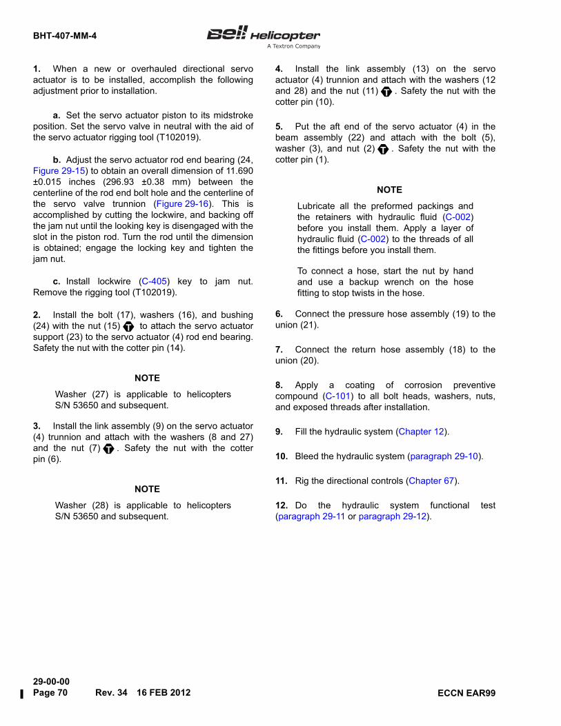
BHT-407-MM-4
29-00-00Page 70 Rev. 34 16 FEB 2012 ECCN EAR99
1. When a new or overhauled directional servoactuator is to be installed, accomplish the followingadjustment prior to installation.
a. Set the servo actuator piston to its midstrokeposition. Set the servo valve in neutral with the aid ofthe servo actuator rigging tool (T102019).
b. Adjust the servo actuator rod end bearing (24,Figure 29-15) to obtain an overall dimension of 11.690±0.015 inches (296.93 ±0.38 mm) between thecenterline of the rod end bolt hole and the centerline ofthe servo valve trunnion (Figure 29-16). This isaccomplished by cutting the lockwire, and backing offthe jam nut until the looking key is disengaged with theslot in the piston rod. Turn the rod until the dimensionis obtained; engage the locking key and tighten thejam nut.
c. Install lockwire (C-405) key to jam nut.Remove the rigging tool (T102019).
2. Install the bolt (17), washers (16), and bushing(24) with the nut (15) to attach the servo actuatorsupport (23) to the servo actuator (4) rod end bearing.Safety the nut with the cotter pin (14).
NOTE
Washer (27) is applicable to helicoptersS/N 53650 and subsequent.
3. Install the link assembly (9) on the servo actuator(4) trunnion and attach with the washers (8 and 27)and the nut (7) . Safety the nut with the cotterpin (6).
NOTE
Washer (28) is applicable to helicoptersS/N 53650 and subsequent.
4. Install the link assembly (13) on the servoactuator (4) trunnion and attach with the washers (12and 28) and the nut (11) . Safety the nut with thecotter pin (10).
5. Put the aft end of the servo actuator (4) in thebeam assembly (22) and attach with the bolt (5),washer (3), and nut (2) . Safety the nut with thecotter pin (1).
NOTE
Lubricate all the preformed packings andthe retainers with hydraulic fluid (C-002)before you install them. Apply a layer ofhydraulic fluid (C-002) to the threads of allthe fittings before you install them.
To connect a hose, start the nut by handand use a backup wrench on the hosefitting to stop twists in the hose.
6. Connect the pressure hose assembly (19) to theunion (21).
7. Connect the return hose assembly (18) to theunion (20).
8. Apply a coating of corrosion preventivecompound (C-101) to all bolt heads, washers, nuts,and exposed threads after installation.
9. Fill the hydraulic system (Chapter 12).
10. Bleed the hydraulic system (paragraph 29-10).
11. Rig the directional controls (Chapter 67).
12. Do the hydraulic system functional test(paragraph 29-11 or paragraph 29-12).
T
T
T
T


![Classical Section V-belts 5, Y/6 and 8...Typ CONTI-V - Profil A/13 - DIN2215 Ld [mm] Ld [mm] Ld [mm] Ld [mm] Ld [mm] Ld [mm] A 16* 407 437 A 46,5 1180 1210 A 85 2160 2190 A 18* 457](https://static.fdocuments.net/doc/165x107/60e95cd6b6215c18f511d258/classical-section-v-belts-5-y6-and-8-typ-conti-v-profil-a13-din2215-ld.jpg)