405 Part ershi Drive. Blacksburg VA 24060 Ph: 540.443 9262 ... · Blacksburg VA 24060 Ph: 540.443...
54
405 Partnership Drive. Blasburg VA 24&0 Ph: 60.443 9262 Fx: 60.443.Ů7 w.torcrobolics com
Transcript of 405 Part ershi Drive. Blacksburg VA 24060 Ph: 540.443 9262 ... · Blacksburg VA 24060 Ph: 540.443...

405 Partnership Drive. Blacksburg VA 24060 Ph: 540.443 9262 Fx: 540.443.3667 www.torcrobolics com

SafeStopTM User Manual, Version 1.8
1
TABLE OF CONTENTS
1 ASSIGNMENT OF LIABILITY ....................................................................................................... 3
2 TECHNICAL SUPPORT .................................................................................................................. 3
3 GENERAL SAFETY INFORMATION............................................................................................ 4
4 PACKAGE CONTENTS ................................................................................................................... 5 4.1 Included Items........................................................................................................................................... 5 4.2 Optional accessories ................................................................................................................................. 6
5 PRODUCT OVERVIEW .................................................................................................................. 8
6 PRODUCT SPECIFICATIONS ..................................................................................................... 10
7 SAFESTOP™ TRANSMITTER ..................................................................................................... 11 7.1 Transmitter Switch Detail ........................................................................................................................ 12 7.2 Transmitter Power Receptacle ................................................................................................................ 12 7.3 Transmitter LED Indicator Detail ............................................................................................................. 14 7.4 Transmitter Audible Alarm ...................................................................................................................... 14
8 SAFESTOP™ OEM TRANSMITTER ........................................................................................... 16 8.1 OEM Transmitter User Interface Connector Detail .................................................................................. 17 8.2 OEM Transmitter DIP Switch Detail ......................................................................................................... 17 8.3 OEM Transmitter LED Detail .................................................................................................................... 18 8.4 OEM Transmitter Serial Commands ........................................................................................................ 18
9 SAFESTOP™ RECEIVER ............................................................................................................... 20 9.1 Receiver Bypass Button Detail ................................................................................................................. 21 9.2 Receiver Power Receptacle Detail ........................................................................................................... 22 9.3 Receiver Safety Receptacle Detail ........................................................................................................... 23 9.4 Receiver Output Circuit Schematic .......................................................................................................... 24 9.5 Receiver LED Indicator Detail .................................................................................................................. 25
10 TCP (TELNET) COMMUNICATIONS ........................................................................................ 26 10.1 TELNET Testing ........................................................................................................................................ 29
11 RS-232 RECEIVER SERIAL COMMUNICATIONS.................................................................. 32

SafeStopTM User Manual, Version 1.8
2
12 WEB CONFIGURATION ............................................................................................................... 33 12.1 System Status .......................................................................................................................................... 33 12.2 System Configuration .............................................................................................................................. 34 12.3 External Watchdogs ................................................................................................................................ 35 12.4 Network Settings ..................................................................................................................................... 36 12.5 Multipoint Transmitters .......................................................................................................................... 37 12.6 Firmware Updates ................................................................................................................................... 40
13 RESTORE NETWORK AND SYSTEM DEFAULTS ................................................................. 42
14 SYSTEM INTEGRATION .............................................................................................................. 43 14.1 Charging the Transmitter Battery ............................................................................................................ 43 14.2 Installing the Antennas ........................................................................................................................... 43 14.3 Installing the Receiver Cables into the Vehicle System ............................................................................ 43 14.4 Example 5V Logic Level Wiring Schematics .............................................................................................. 43 14.5 Example Vehicle Wiring Schematics ........................................................................................................ 44 14.6 Example External Button Wiring Schematics ........................................................................................... 45 14.7 Verify Operation of the System ............................................................................................................... 45
15 PHYSICAL DIMENSIONS ............................................................................................................. 48 15.1 SafeStop™ Transmitter Dimensions ........................................................................................................ 48 15.2 Transmitter Mount Dimensions .............................................................................................................. 49 15.3 SafeStop™ OEM Transmitter Dimensions ................................................................................................ 50 15.4 SafeStop™ Receiver Dimensions ............................................................................................................. 51 15.5 SafeStop™ Receiver Mounting Template ................................................................................................. 51
16 FCC COMPLIANCE ........................................................................................................................ 53
17 LIMITED WARRANTY ................................................................................................................. 53

SafeStopTM User Manual, Version 1.8
3
1 ASSIGNMENT OF LIABILITY
WARNING: DO NOT OPERATE UNTIL USER MANUAL IS REVIEWED AND UNDERSTOOD. PRODUCT USE IS SUBJECT TO STRICT TERMS AND CONDITIONS. SEE TERMS AND CONDITIONS DOCUMENT FOR ADDITIONAL USE RESTRICTIONS. OPERATING PRODUCT IN VIOLATION OF USER RESTRICTIONS COULD RESULT IN PRODUCT MALFUNCTION, PROPERTY DAMAGE, AND PERSONAL INJURY INCLUDING DEATH.
NOTICE: USER ASSUMES ALL RISKS ASSOCIATED WITH POSSESSION OR USE OF PRODUCT AND RELATED SYSTEMS. USER AGREES TO INDEMNIFY, DEFEND AND HOLD HARMLESS TORC ROBOTICS, Inc. (“TORC®”) FROM ANY DAMAGES ARISING OUT OF POSSESSION OR USE OF PRODUCT AND RELATED SYSTEMS. TORC IS NOT LIABLE FOR ANY DAMAGES OF ANY KIND.
NOTICE: SEE TERMS AND CONDITIONS FOR ALL TERMS APPLICABLE TO USE OF THE PRODUCT OR RELATED SOFTWARE.
2 TECHNICAL SUPPORT
For technical assistance and repairs, please use the following contact information:
Mailing Address Email & Phone Support
TORC Product Support
405 Partnership Drive
Blacksburg, VA 24060
www.torcrobotics.com
Phone: (540) 443-9262
Copyright © 2015 TORC Robotics, Inc. All Rights Reserved.
All information contained in this manual is believed to be accurate at the time of printing, however, TORC Robotics, Inc. reserves the right to make modifications to the specifications and operation of this product without obligation to notify any person or entity of such revision.

SafeStopTM User Manual, Version 1.8
4
3 GENERAL SAFETY INFORMATION
The following symbols are used throughout the user manual to indicate a particularly hazardous condition.
WARNING: Indicates a hazardous condition that could result in serious injury or loss of life if not performed properly.
CAUTION: Indicates a hazardous condition or procedure that could result in damage to this product, or loss related to equipment malfunction.
NOTE: A note indicates information that may not be applicable regarding system safety but needs to be known for best system performance.
Use Redundant Safety Measures This product is not intended to be used as the only safety stop device. It is the user’s responsibility to ensure that adequate and redundant safety measures are implemented.
Use Proper Supplied Accessories To prevent damage to the product, use only the recommended accessories, including power adapters, antennas, and cables.
Observe All Connector Ratings To avoid shock hazard and/or damage to the product, do not exceed any voltage, current, or environmental ratings on any of the connectors.
Do Not Charge Unattended To avoid fire hazard and/or damage to the product, monitor the SafeStop™ transmitter when connected to an external power supply.
Do Not Operate With Suspected Failures If you suspect there is damage to the product, contact TORC to have it inspected before further use.
Do Not Modify or Disassemble To avoid shock hazard and/or damage to the product, do not attempt to open the case, make modifications, or repair the device. Opening, modifying or repairing this device will void any applicable warranty and could prevent the device from operating properly.
Do Not Operate in Explosive Atmosphere To avoid a fire hazard, do not operate in an explosive atmosphere, such as in the presence of flammable liquids or gases.

SafeStopTM User Manual, Version 1.8
5
Use Within Range To prevent unreliable operation, do not use this product outside of its specified range. A range check should be performed before using the SafeStop™ system.
4 PACKAGE CONTENTS
4.1 Included Items After unpacking the contents, please verify the contents of the package includes the following items:
Qty Part Number Description
1 SS03TX** SafeStop™
Transmitter unit
1 SS03RX** SafeStop™ Receiver
unit
2 ANT**01 Flexible Antenna (900 MHz antenna shown)
1 SS03ACC-1 AC Power Adapter /
Charger for SafeStop™ Transmitter
1 SS03SFT 60” Safety Cable for SafeStop™ Receiver

SafeStopTM User Manual, Version 1.8
6
1 SS03PWR 60” Power Cable for SafeStop™ Receiver
2 SS03ETH Ethernet Plugs for
SafeStop™ Receiver
2 SS03ECP Ethernet Caps for
SafeStop™ Receiver
** Designates the frequency band: 04= 400 MHz, 09= 900 MHz, 13= 1.3 GHz, 24= 2.4 GHz
4.2 Optional accessories Accessory Part Number Function
External Emergency Stop Button
SS03A001
Allows the user to place an Emergency Stop button on the exterior of a vehicle. Magnetic base with hard mount points.
External Emergency Override Button
SS03A002
Allows the user to place an Emergency Override button on the exterior of a vehicle. Magnetic base with hard mount points.
Transmitter Car Charger
SS03A003
Provides the user the ability to conveniently charge the SafeStop™ transmitter from any standard 12V automobile outlet.

SafeStopTM User Manual, Version 1.8
7
Transmitter Bind Plug
SS03A004 Allows the pairing of a transmitter unit to any receiver.
Serial Interface Cable
SS03A005 Allows the user to interface with the receiver using the legacy RS-232 interface.
ANT**02 External high gain antenna with magnetic mount. (900 MHz antenna shown)
*Standard RAM mount accessories are available for a variety of transmitter mounting options.

SafeStopTM User Manual, Version 1.8
8
5 PRODUCT OVERVIEW
The SafeStop™ is a multi-level wireless emergency stop system, consisting of the SS03TX transmitter and the SS03RX receiver. The SafeStop™ system provides the ability to safely command an unmanned or autonomous vehicle to pause or stop from a remote location up to 6 miles away. The compact and lightweight transmitter contains an internal rechargeable battery that enables continuous operation for up to 12 hours. Two hardware outputs are available for the user on the SS03RX receiver: an emergency stop output and an emergency override output. Each of these outputs can be overridden with hardwired external buttons, however only the emergency stop output is remotely controlled by the SS03TX transmitter. The status of all of the outputs and inputs can be read from a simple TCP interface through either of the two Ethernet ports on the receiver. An audible alarm and indicator lights provide user feedback of system state, link status, and battery life. System configuration and firmware updates are accessed using a web-based configuration interface. For manned operation, the wireless link may also be disabled using a bypass switch on the receiver.
Figure 5-1: System Integration Example
The SafeStop™ has three safety modes: pause, emergency stop, and emergency override. Pause mode is intended to indicate a temporary pause in autonomous or unmanned vehicle operation and is considered to be a software only condition. There is no hardware output associated with the pause state. Emergency stop mode is intended to indicate a serious hardware or software condition that should cause the vehicle to be immediately disabled. The hardware emergency stop output is controlled by a red emergency stop button on the transmitter. Emergency
SafeStopTM User Manual, Version 1.8
9
override mode is intended to be used to be a hardware only condition that entirely bypasses the SafeStop™ embedded software to disable the system.
The safety architecture of the SafeStop™ receiver implements the use of two independent processors that continuously monitor the system. In order for a vehicle to be placed in a running state both processors must be in agreement. If a discrepancy is detected, each processor has the ability to individually place the system in an emergency stop state. In addition, the code on the secondary processor on the receiver meets the Motor Industry Software Reliability Association Guidelines for the use of the C language in critical systems (MISRA-C:2004). The SafeStop™ receiver also includes redundant network ports and power inputs.
Multiple SS03 transmitters may be used to control a single SS03 SafeStop™ receiver. Configured through the webpage, a user may select up to 10 SafeStop™ transmitters to simultaneously control a single SafeStop™ receiver. The effective range of the SafeStop™ system can be increased by utilizing multiple transmitters.
SafeStopTM User Manual, Version 1.8
10
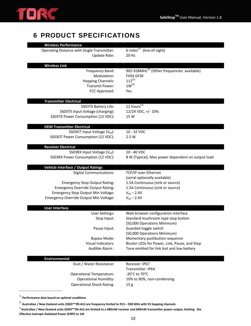
6 PRODUCT SPECIFICATIONS Wireless Performance
Operating Distance with Single Transmitter: 6 miles(1) (line-of-sight)
Update Rate: 20 Hz
Wireless Link
Frequency Band: 902-928MHz(2) (Other frequencies available) Modulation: FHSS GFSK
Hopping Channels: 112(2)
Transmit Power: 1W(3) FCC Approved: Yes
Transmitter Electrical
SS03TX Battery Life: 12 hours(1) SS03TX Input Voltage (charging):
SS03TX Power Consumption (12 VDC): 12/24 VDC, +/- 10%
15 W OEM Transmitter Electrical
SS03OT Input Voltage (VIN): 10 - 32 VDC SS03OT Power Consumption (12 VDC): 2.5 W
Receiver Electrical
SS03RX Input Voltage (VIN): SS03RX Power Consumption (12 VDC):
10 - 40 VDC 8 W (Typical), Max power dependent on output load
Vehicle Interface / Output Ratings Digital Communications: TCP/IP over Ethernet
(serial optionally available) Emergency Stop Output Rating: 1.5A Continuous (sink or source)
Emergency Override Output Rating: Emergency Stop Output Min Voltage:
Emergency Override Output Min Voltage:
1.5A Continuous (sink or source) VIN – 2.4V VIN – 2.4V
User Interface
User Settings: Web browser configuration interface Stop Input: Standard mushroom type stop button
(50,000 Operations Minimum) Pause Input: Guarded toggle switch
(50,000 Operations Minimum) Bypass Mode: Momentary pushbutton sequence
Visual Indicators: Bicolor LEDs for Power, Link, Pause, and Stop Audible Alarm : Tone emitted for link lost and low battery
Environmental
Dust / Water Resistance: Receiver: IP67 Transmitter: IP64
Operational Temperature: -20°C to 70°C Operational Humidity: 10% to 90%, non-condensing
Operational Shock Rating: 15 g ______________________________
1: Performance data based on optimal conditions 2: Australian / New Zealand units (SS03**09-AU) are frequency limited to 915 – 928 MHz with 55 hopping channels 3: Australian / New Zealand units (SS03**09-AU) are limited to a 480mW receiver and 600mW transmitter power output, limiting the Effective Isotropic Radiated Power (EIRP) to 1W
SafeStopTM User Manual, Version 1.8
11
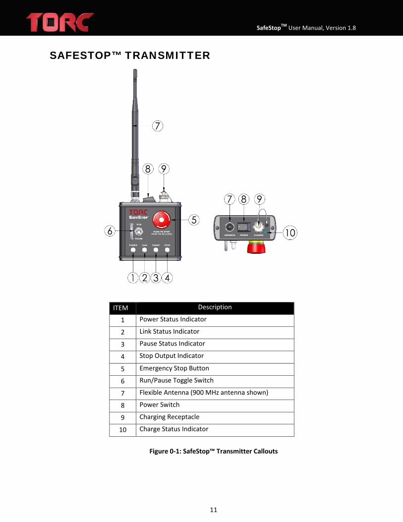
SAFESTOP™ TRANSMITTER
Figure 0-1: SafeStop™ Transmitter Callouts
ITEM Description
1 Power Status Indicator
2 Link Status Indicator
3 Pause Status Indicator
4 Stop Output Indicator
5 Emergency Stop Button
6 Run/Pause Toggle Switch
7 Flexible Antenna (900 MHz antenna shown)
8 Power Switch
9 Charging Receptacle
10 Charge Status Indicator

SafeStopTM User Manual, Version 1.8
12
7.1 Transmitter Switch Detail There are three switches located on the transmitter: the Power rocker switch, the Pause/Run toggle switch, and the Emergency Stop button.
When the Power rocker switch is in the “1” position, the transmitter is powered. With the switch in the “0” position, the transmitter is shut down and will no longer receive or transmit data.
The Pause/Run toggle switch is used to update the status message sent over TCP/IP or serial by the receiver. Flip the switch up to put the system in run mode, and down to put the system in pause mode. For details of this message, see section 9.
The Emergency Stop button is a push-to-stop/turn-to-release style mushroom button and controls the emergency stop output line on the receiver. When pushed, the emergency stop output is pulled to GND, and when released the emergency stop output is connected to VIN.
7.2 Transmitter Power Receptacle The transmitter Power Receptacle is used for charging the internal rechargeable battery and powering the transmitter from an external power source such as the transmitter car charger (P/N: SS03A003).
WARNING: Do not leave the SafeStop™ transmitter unattended while charging the battery.
WARNING: Only charge the battery using an approved power adapter
WARNING: Only charge the battery at room temperature.
WARNING: Replace the included connector end cap when finished charging the transmitter. The transmitter environmental ratings are only valid when mated to the charger or the end cap is installed.

SafeStopTM User Manual, Version 1.8
13
Figure 0-2: Transmitter Power Receptacle Detail
Pin Description
1 Power Input
2 Factory Use Only
3 Ground (GND)
4 Factory Use Only
5 Factory Use Only
6 Factory Use Only
7 Factory Use Only
8 Factory Use Only
SafeStopTM User Manual, Version 1.8
14
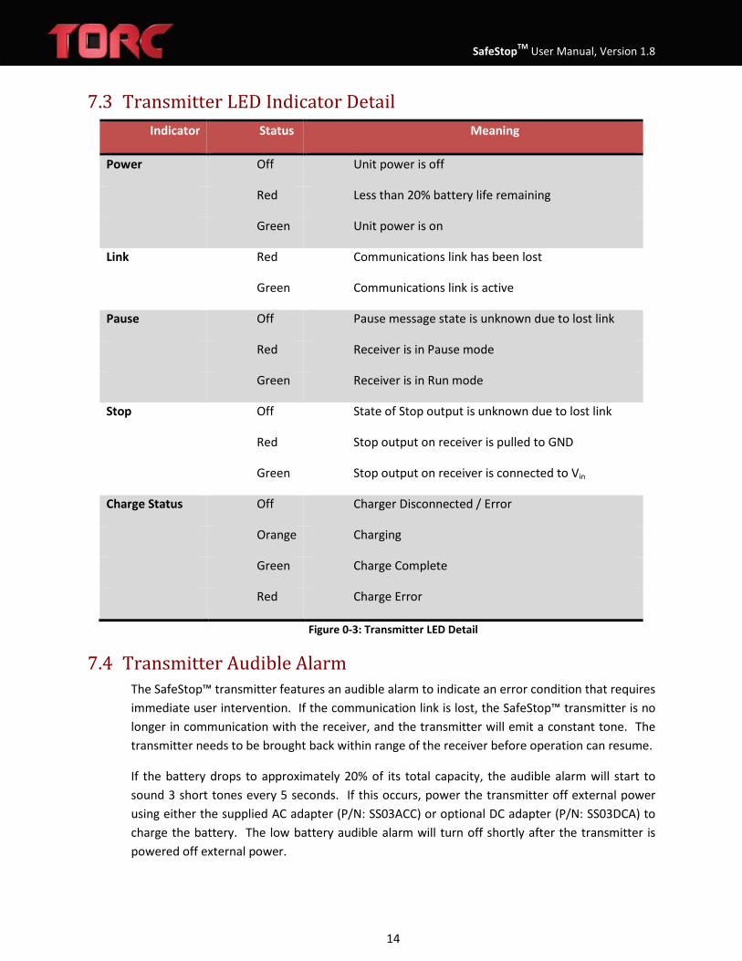
7.3 Transmitter LED Indicator Detail Indicator Status Meaning
Power Off Unit power is off
Red Less than 20% battery life remaining
Green Unit power is on
Link Red Communications link has been lost
Green Communications link is active
Pause Off Pause message state is unknown due to lost link
Red Receiver is in Pause mode
Green Receiver is in Run mode
Stop Off State of Stop output is unknown due to lost link
Red Stop output on receiver is pulled to GND
Green Stop output on receiver is connected to Vin
Charge Status Off Charger Disconnected / Error
Orange Charging
Green Charge Complete
Red Charge Error
Figure 0-3: Transmitter LED Detail
7.4 Transmitter Audible Alarm The SafeStop™ transmitter features an audible alarm to indicate an error condition that requires immediate user intervention. If the communication link is lost, the SafeStop™ transmitter is no longer in communication with the receiver, and the transmitter will emit a constant tone. The transmitter needs to be brought back within range of the receiver before operation can resume.
If the battery drops to approximately 20% of its total capacity, the audible alarm will start to sound 3 short tones every 5 seconds. If this occurs, power the transmitter off external power using either the supplied AC adapter (P/N: SS03ACC) or optional DC adapter (P/N: SS03DCA) to charge the battery. The low battery audible alarm will turn off shortly after the transmitter is powered off external power.

SafeStopTM User Manual, Version 1.8
15
Alarm Meaning
Continuous Communication link with receiver has been lost
Three Short Tones Less than 20% battery life remaining
Figure 0-4: Transmitter Audible Alarm Detail

SafeStopTM User Manual, Version 1.8
16
7 SAFESTOP™ OEM TRANSMITTER
ITEM Description
1 Power Status Indicator
2 Link Status Indicator
3 Pause State Indicator
4 Stop Output Indicator
5 User Interface Connector
6 Wireless Modem
7 MMCX RF Connection
8 External Modem Connector
9 DIP Switches

SafeStopTM User Manual, Version 1.8
17
8.1 OEM Transmitter User Interface Connector Detail Mating Connector Manufacturer: JST Mating Connector Manufacturer Part Number: PADP-16V-1-S
PIN FUNCTION
1 POWER
2 GROUND
3 POWER
4 GROUND
5 Factory Use Only (Connect Directly to Power Pin)
6 STOP LOOP LOW
7 N.C.
8 STOP LOOP HIGH
9 Factory Use Only
10 Factory Use Only
11 Factory Use Only
12 Factory Use Only
13 PRIMARY RS-232 RX, RS-422 RX-
14 PRIMARY RS-422 RX+
15 PRIMARY RS-232 TX, RS-422 TX-
16 PRIMARY RS-422 TX+
8.2 OEM Transmitter DIP Switch Detail DIP
SWITCH FUNCTION OFF ON
1 RESERVED (Keep in OFF position) NORMAL NONE
2 PRIMARY SERIAL MODE RS-232 RS-422
3 BIND MODE DISABLED ENABLED
4 RESERVED (Keep in OFF position) NORMAL NONE
5 RESERVED (Keep in OFF position) NORMAL NONE
6 RESERVED (Keep in OFF position) NORMAL NONE
7 PRIMARY SERIAL TERMINATION DISABLED ENABLED
8 AUX SERIAL TERMINATION DISABLED ENABLED

SafeStopTM User Manual, Version 1.8
18
8.3 OEM Transmitter LED Detail Indicator Status Meaning
Power Off Unit power is off
Red N/A (LED should always remain green when on)
Green Unit power is on
Link Red Communications link has been lost
Green Communications link is active
Pause Off Pause message state is unknown due to lost link
Red Receiver is in Pause mode
Green Receiver is in Run mode
Stop Off State of Stop output is unknown due to lost link
Red Stop output on receiver is pulled to GND
Green Stop output on receiver is connected to Vin
Figure 7-1: OEM Transmitter LED Detail
8.4 OEM Transmitter Serial Commands The OEM SafeStop™ can be controlled by issuing commands over the Primary RS-232/422 interface. Serial port settings are 15200 bps, 8-N-1. Commands are not case sensitive. The following commands are supported:
PAUSE – commands a paused to the receiver, this is identical to commanding a pause using the pause toggle switch on the handheld transmitter
Usage: PAUSE<CR><LF> Response: none
UNPAUSE – commands an un-paused state to the receiver Usage: UNPAUSE<CR><LF> Response: none
BIND – similar to using a bind plug for multi-point operation, the bind command places the OEM transmitter into discovery mode
Usage: BIND<CR><LF> Response: none

SafeStopTM User Manual, Version 1.8
19
STATUS – returns the status of the SafeStop™ system
Usage: STATUS@<rate><CR><LF> Response: XYZ<CR><LF>
First Character (X) Meaning
X Communications Timed Out L Communications Linked
Second Character (Y) Value P Paused R Running
Third Character (Z) Value S Stopped R Running
VOLTAGE – returns the voltage of the supply connected to the OEM transmitter
Usage: VOLTAGE<CR><LF> Response: xy.zV<CR><LF>
TEMPERATURE – returns the PCB temperature of the OEM transmitter
Usage: TEMPERATURE<CR><LF> Response: wxy.zC<CR><LF> (or “NULL<CR><LF>” if unavailable) HELP – returns a list of supported commands
Usage: HELP<CR><LF> Response: display a summary of available commands

SafeStopTM User Manual, Version 1.8
20
8 SAFESTOP™ RECEIVER
ITEM Description
1 Power Status Indicator
2 Link Status Indicator
3 Pause State Indicator
4 Stop Output Indicator
5 Bypass Pushbutton
6 RJ-45 Ethernet Jack
7 RJ-45 Ethernet Jack
8 Safety Receptacle
9 Power Receptacle
10 Antenna Connector
Figure 8-1: SafeStop™ Receiver Callouts

SafeStopTM User Manual, Version 1.8
21
9.1 Receiver Bypass Button Detail The SafeStop™ receiver features an illuminated pushbutton used to enable Bypass Mode. Bypass mode causes the receiver to ignore wireless transmitter commands and link loss conditions, and therefore should only be used during manned operation. The emergency stop and emergency override external inputs are still active and can cause a stop or override condition through the use of wired external buttons. When in bypass mode, the bypass button will be illuminated blue, the Pause indicator will be green, and the stop indicator will reflect the status of the external emergency stop button loop. Even though the receiver ignores wireless commands from all transmitters while in bypass mode, the link LED will reflect actual link status. If the link LED is green prior to exiting bypass mode, the receiver will immediately transition to the state of the connected transmitter upon exiting.
WARNING: While in Bypass Mode, the receiver will not accept Stop or Pause commands from the transmitter.
NOTE: Turning on power to a transmitter linked to a receiver placed in bypass mode will cause the transmitter to act as if the link is lost, sounding the audible alarm.
ENTER BYPASS MODE To enable Bypass Mode the user must follow a deliberate procedure designed to prevent accidental entry into Bypass Mode by untrained personnel. This procedure is outlined below.
1. Press the Bypass button. The blue ring will illuminate after a random delay between 0.2 and 2 seconds.
2. While the blue ring is illuminated press the Bypass button again. This will turn off the blue ring for another random delay between 0.2 and 2 seconds.
3. While the blue ring is illuminated, press the Bypass button a third time 4. If the Bypass procedure was completed successfully the blue ring will remain
illuminated. 5. If, however, at any point the Bypass procedure was unsuccessful the blue ring will
begin to flash. At this point the user must wait for the flashing to stop and begin the process again.
EXIT BYPASS MODE To exit bypass mode press and release the bypass button. Once released the blue illumination ring will turn off and the receiver will wait up the user defined timeout delay for a wireless link to the transmitter before executing the timeout action. It is possible to prevent the SafeStop™ receiver from executing the timeout action when exiting bypass by ensuring that there is an active link with a transmitter. The link LED only on the receiver illuminates green when an active link is detected in bypass mode. If no link is detected the link LED will illuminate red. The transmitter link LED will always illuminate red when the receiver is placed in bypass mode.
SafeStopTM User Manual, Version 1.8
22
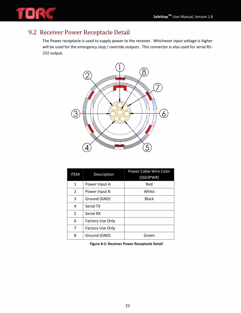
9.2 Receiver Power Receptacle Detail The Power receptacle is used to supply power to the receiver. Whichever input voltage is higher will be used for the emergency stop / override outputs. This connector is also used for serial RS-232 output.
ITEM Description Power Cable Wire Color
(SS03PWR) 1 Power Input A Red
2 Power Input B White
3 Ground (GND) Black
4 Serial TX
5 Serial RX
6 Factory Use Only
7 Factory Use Only
8 Ground (GND) Green
Figure 8-2: Receiver Power Receptacle Detail
SafeStopTM User Manual, Version 1.8
23
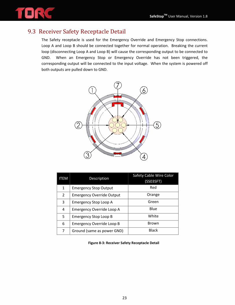
9.3 Receiver Safety Receptacle Detail The Safety receptacle is used for the Emergency Override and Emergency Stop connections. Loop A and Loop B should be connected together for normal operation. Breaking the current loop (disconnecting Loop A and Loop B) will cause the corresponding output to be connected to GND. When an Emergency Stop or Emergency Override has not been triggered, the corresponding output will be connected to the input voltage. When the system is powered off both outputs are pulled down to GND.
ITEM Description Safety Cable Wire Color
(SS03SFT) 1 Emergency Stop Output Red
2 Emergency Override Output Orange
3 Emergency Stop Loop A Green
4 Emergency Override Loop A Blue
5 Emergency Stop Loop B White
6 Emergency Override Loop B Brown
7 Ground (same as power GND) Black
Figure 8-3: Receiver Safety Receptacle Detail

SafeStopTM User Manual, Version 1.8
24
9.4 Receiver Output Circuit Schematic There are two independent processors within the receiver that have control over the Emergency Stop Output. Each processor verifies correct operation of the system and will deactivate the emergency stop output if an error is detected. While each processor can individually ground the Emergency Stop Output, both processors must be in agreement for the Emergency Stop Output to be driven to the input voltage VIN. When driven high, both the Emergency Stop and Emergency Override Outputs will be driven to VIN through several diode drops, resulting in a minimum output voltage of VIN – 1.6VDC.
In addition, the Emergency Stop Output is controlled by any external buttons that may be connected to the Emergency Stop Loop A and Loop B pins. If the Emergency Stop Loop A and Loop B pins are left unconnected, the Emergency Stop Output will always be driven low regardless of the commands from the SafeStop™ transmitter. The button loops for both Emergency Stop and Override outputs are current loops that do not require any external power sources. When Loop A and Loop B pins are connected together, an internal current source will supply approximately 15mA through the loop.
CAUTION: The Emergency Stop and Emergency Override button loops have internal current supplies and do not require external power.
To ensure the Emergency Output Line is pulled low when power is disconnected from the SafeStop™ receiver, an internal pull-down resistor of 2.49kΩ is connected to the Emergency
Stop Output and Emergency Override lines. The Emergency Stop Output is also fused internally.
Primary Processor
Control
Secondary Processor
Control
Emergency Stop
Button Loop Logic
Primary Processor
Control
Secondary Processor
Control
Emergency Stop
Button Loop Logic
2.49KΩ
Emergency Stop OutputVIN
Figure 8-4: Emergency Stop Output Schematic
Unlike the Emergency Stop Output, the Emergency Override Output is not software controlled by the processors. The Emergency Override Output is only controlled through the Emergency
SafeStopTM User Manual, Version 1.8
25
Override button loop. When Emergency Override Loop A (Safety connector pin4) and Emergency Override Loop B (Safety connector pin 6) are connected the Emergency Override Output is driven high to VIN, otherwise the output is driven to GND. When power is disconnected a pull down of 2.49kΩ will pull the outputs to ground.
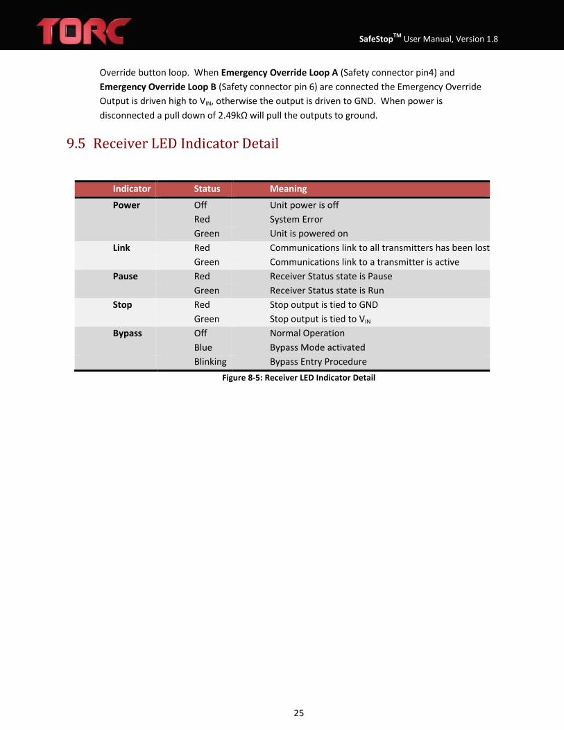
9.5 Receiver LED Indicator Detail
Indicator Status Meaning
Power Off Red Green
Link Red Green
Pause Red Green
Stop Red Green
Bypass Off Blue Blinking
Unit power is off System Error Unit is powered on Communications link to all transmitters has been lost Communications link to a transmitter is active Receiver Status state is Pause Receiver Status state is Run Stop output is tied to GND Stop output is tied to VIN Normal Operation Bypass Mode activated Bypass Entry Procedure
Figure 8-5: Receiver LED Indicator Detail

SafeStopTM User Manual, Version 1.8
26
9 TCP (TELNET) COMMUNICATIONS The SafeStop™ accepts TCP ASCII commands. All commands are one word commands followed by a carriage return (0x0D) character and new line (0x0A) character. Only NVT(Network Virtual Terminal) ASCII characters are valid, and any telnet option requests will trigger a WONT or DONT response (See RFC 854 for details). This permits the use of either a standard telnet client (such as Putty) or a raw TCP connection to port 23.
STOP – returns the state of the wired emergency stop output Usage: STOP<0x0D><0x0A>
Command: STOP<0x0D><0x0A>
Possible Response Meaning
STOP NONE<0x0D><0x0A> The emergency stop button loop is closed, there are no other stop conditions, and the emergency stop
output is tied to VIN
STOP WIRELESS<0x0D><0x0A> The receiver has received a transmitter stop
command, the emergency stop output is tied to GND
STOP WIRELESS WIRED<0x0D><0x0A> The emergency stop button loop is open and the
transmitter is sending an emergency stop command, the emergency stop output is tied to GND
STOP TIMEOUT<0x0D><0x0A> There is no link between the receiver and transmitter, the user configured timeout action will be executed,
the emergency stop output is tied to GND
STOP TIMEOUT WIRED<0x0D><0x0A> The emergency stop button loop is open and there is
no link between the receiver and transmitter, the emergency stop output is tied to GND
STOP WIRED<0x0D><0x0A> The emergency stop button loop is open, the
emergency stop output is tied to GND
STOP WATCHDOG<0x0D><0x0A> The external watchdog timer has expired, the user
configured timeout action will be executed, the emergency stop output is tied to GND
STOP WIRELESS WATCHDOG<0x0D><0x0A>
The receiver has received a transmitter stop command, the external watchdog timer has expired,
the emergency stop output is tied to GND
STOP WIRELESS WIRED WATCHDOG<0x0D><0x0A>
The emergency stop button loop is open and the transmitter is sending an emergency stop command,
the external watchdog timer has expired, the emergency stop output is tied to GND
STOP TIMEOUT WATCHDOG<0x0D><0x0A>
There is no link between the receiver and transmitter, the external watchdog timer has expired, the user

SafeStopTM User Manual, Version 1.8
27
OVERRIDE – returns the state of the wired emergency override output
Usage: OVERRIDE<0x0D><0x0A>
PAUSE – returns the state of the PAUSE toggle switch on the transmitter. Without any hardware pause outputs on the receiver, the only way to detect the state of the pause switch is in software through the pause command.
Usage: PAUSE<0x0D><0x0A>
configured timeout action will be executed, the emergency stop output is tied to GND
STOP TIMEOUT WIRED WATCHDOG<0x0D><0x0A>
The emergency stop button loop is open and there is no link between the receiver and transmitter, the
external watchdog timer has expired, the emergency stop output is tied to GND
STOP WIRED WATCHDOG<0x0D><0x0A>
The emergency stop button loop is open, the external watchdog timer has expired, the emergency stop
output is tied to GND
STOP LATCHED<0x0D><0x0A>
Latching stop is enabled, a stop even has occurred but has been cleared, and the system requires a
wired stop to clear the stop status, the emergency stop output is tied to GND
STOP TRANSITION<0x0D><0x0A>
The secondary processor has cleared the stop but the message from secondary to primary has not yet been processed, the emergency stop output is tied to GND.
NOTE: This state should only be seen temporarily between other states.
Command: OVERRIDE<0x0D><0x0A>
Possible Response Meaning
OVERRIDE WIRED<0x0D><0x0A> The emergency override button loop is open, the
override output is tied to GND
OVERRIDE NONE<0x0D><0x0A> The emergency override button loop is closed, the
emergency override output is tied to VIN
Command: PAUSE<0x0D><0x0A>
Possible Response Meaning
PAUSE TIMEOUT<0x0D><0x0A> There is no link between the receiver and a
transmitter
PAUSE WIRELESS<0x0D><0x0A> The receiver has received a transmitter pause
command

SafeStopTM User Manual, Version 1.8
28
LINK – returns the status of the wireless link between the SafeStop™ receiver and transmitter Usage: LINK<0x0D><0x0A>
TXSTATUS – returns the status of all transmitters currently in control of the receiver
Usage: TXSTATUS<0x0D><0x0A>
WATCHDOG – returns the status of the external watchdog
PAUSE WATCHDOG<0x0D><0x0A> The external watchdog has expired
PAUSE TIMEOUT WATCHDOG<0x0D><0x0A>
There is no link between the receiver and any transmitter, and the external watchdog has expired
PAUSE WIRELESS WATCHDOG<0x0D><0x0A>
The receiver has received a transmitter pause command and the external watchdog has expired
PAUSE NONE<0x0D><0x0A> The Run/Pause toggle switch on the transmitter has
been placed in the Run position
Command: LINK<0x0D><0x0A>
Possible Response Meaning
LINK BYPASS<0x0D><0x0A> Receiver has been placed into bypass
LINK 0%<0x0D><0x0A> No wireless link detected
LINK XX%<0x0D><0x0A> Wireless link active, signal strength at XX%
Command: TXSTATUS<0x0D><0x0A>
Possible Response Meaning
TXID NONE<0x0D><0x0A> No active transmitter links
TXID VVVV: Status=0xWW Link=XX% Batt=YY% FW=ZZ
Transmitter ID “VVVV” stats displayed, repeated for each transmitter with an active link, “WW” indicates transmitter status code, “XX” indicates transmitter signal strength, “YY” indicates transmitter battery
level, and ZZ indicates transmitter firmware revision

SafeStopTM User Manual, Version 1.8
29
Usage: WATCHDOG<0x0D><0x0A>
FEED – does not return a response. Resets the countdown timer on the external watchdog. When the external watchdog is enabled, this message must be sent periodically to prevent the external watchdog from expiring.
Usage: FEED<0x0D><0x0A>
INFO – returns the SafeStop™ system firmware revision information Usage: INFO<0x0D><0x0A>
VERSION – returns the SafeStop™ TCP communications protocol version Usage: VERSION<0x0D><0x0A>
HELP – returns a list of supported commands Usage: HELP<0x0D><0x0A>
To avoid having to query a message multiple times, some messages may be set up to periodically transmit at rates from 0 to 20 Hz. This is accomplished by appending the ‘@’ character followed by an ASCII integer from 0-20. The commands that generate periodic messages are: STOP, OVERRIDE, PAUSE, LINK, and TXSTATUS. For example: LINK@20<0x0D><0x0A> - periodically transmit the link status at a rate of 20Hz STOP@1<0x0D><0x0A> - transmit the state of the wired emergency stop contact once a second PAUSE@0<0x0D><0x0A> - disable periodic transmission of the pause command
10.1 TELNET Testing To test the telnet interface on the SafeStop™, a standard telnet client such as PuTTY may be downloaded from the internet. In order to communicate with the SafeStop™ receiver, make sure to configure the connecting computer to be on the same network as the SafeStop™. For example, changing your computer’s IP address to a static address of 192.168.0.100 will allow you to communicate with the SafeStop™ receiver when set to use the default IP address of 192.168.0.160. To configure the PuTTY telnet client for testing the SafeStop™ advanced communication protocol, follow the steps outlined below.
Command: WATCHDOG<0x0D><0x0A>
Possible Response Meaning
WATCHDOG DISABLED<0x0D><0x0A> External watchdog is disabled (set to 0)
WATCHDOG RUNNING(xx ms) <0x0D><0x0A>
External watchdog is enabled and running with a time limit of xx milliseconds.
WATCHDOG EXPIRED(xx ms) <0x0D><0x0A>
External watchdog is enabled and expired with a time limit of xx milliseconds.

SafeStopTM User Manual, Version 1.8
30
In the “Session” menu, enter the IP address of the SafeStop™ and select the “Telnet” connection type (will auto-fill Port 23). These settings can be saved for future use by clicking the “Save” button. Once configured, click the “Open” button to create a TCP connection to the SafeStop™.
Figure 9-1: PuTTy Configuration
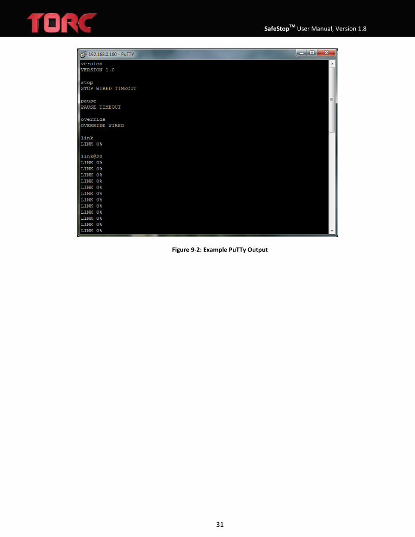
Once a session has been opened commands can be sent to the SafeStop™ receiver. In the figure below, the stop, pause, override, and link commands were sent to the receiver and the outputs can be seen.
SafeStopTM User Manual, Version 1.8
31
Figure 9-2: Example PuTTy Output
SafeStopTM User Manual, Version 1.8
32
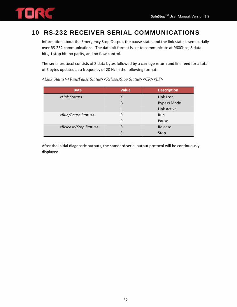
10 RS-232 RECEIVER SERIAL COMMUNICATIONS Information about the Emergency Stop Output, the pause state, and the link state is sent serially over RS-232 communications. The data bit format is set to communicate at 9600bps, 8 data bits, 1 stop bit, no parity, and no flow control.
The serial protocol consists of 3 data bytes followed by a carriage return and line feed for a total of 5 bytes updated at a frequency of 20 Hz in the following format:
<Link Status><Run/Pause Status><Release/Stop Status><CR><LF>
Byte Value Description
<Link Status> X Link Lost B Bypass Mode L Link Active
<Run/Pause Status> R Run P Pause
<Release/Stop Status> R Release S Stop
After the initial diagnostic outputs, the standard serial output protocol will be continuously displayed.

SafeStopTM User Manual, Version 1.8
33
11 WEB CONFIGURATION The SafeStop™ receiver has a built in web server that allows the user to configure the system through a standard web browser. The default IP address for the SafeStop™ is 192.168.0.160.
12.1 System Status The System Status webpage allows for the monitoring of the current state of the SafeStop™ system. The first table shows the overall status of the system: receiver input voltage, receiver internal temperature, as well as the current run states: link, pause, stop, bypass, emergency override, timeout, and external watchdog status.
The second table contains a list of currently paired transmitters if any, and the state of each. It lists each paired transmitter by numerical ID, shows the pause, stop, and timeout status of the transmitter, as well as the radio link quality between the transmitter and the receiver, the current transmitter battery level, and current transmitter firmware version.
NOTE: The system status page refreshes every five seconds, so the webpage display may not reflect the most recent state of the system.
Figure 11-1: Status Webpage

SafeStopTM User Manual, Version 1.8
34
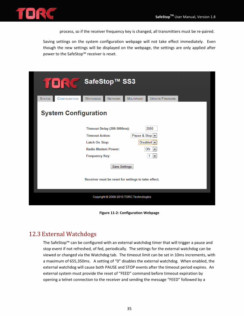
12.2 System Configuration The System Configuration webpage allows for the configuration of the system timeout delay, timeout action, latching stop action, radio modem power, radio modem frequency key, and the serial port baud rate.
The Timeout Delay is the amount of time the SafeStop™ receiver or transmitter will wait before deciding if wireless communications are lost. When wireless communications are lost, the link LED on both the transmitter and receiver will be red and the receiver will perform the user selected Timeout Action. The Timeout Delay can be set from 200 to 5000 milliseconds in 25 millisecond increments.
There are two Timeout Actions that the SafeStop™ receiver can perform upon a loss of communication between the receiver and transmitter. By default the Timeout Action is set to “Pause & Stop” where the receiver will return a PAUSE TIMEOUT in response to the PAUSE command in addition to pulling the Emergency Stop output contact to GND. If the Timeout Action is set to “Pause Only” then the state of the Emergency Stop Output will not change on a loss of communications. The only action taken on a loss of communications when the Timeout Action is set to “Pause Only” is the software response of PAUSE TIMEOUT.
System configuration also allows for selection between latching and non-latching operation. Latching mode can be selected with the “Latch On Stop” setting. When “Latch On Stop” is disabled, simply clearing all stop signals will exit a stopped state. When “Latch On Stop” is enabled, the only way to exit a stopped state is to make sure all stop signals are cleared, and to then press and release the wired stop button. Note that when enabled, the SafeStop™ system will always power up in a stopped state, and the wired stop button must be pressed and released.
In some instances it may be necessary to disable all wireless transmissions by the receiver. This can be accomplished by setting the “Radio Modem Power” to OFF, which will turn off power to the radio modem the next time the receiver is turned on. Turning the “Radio Modem Power” OFF will disable wireless communications between the SafeStop™ receiver and transmitter. In order to resume normal operation of the SafeStop™ system, “Radio Modem Power” must be set to ON and the receiver must cycle power.
The radio modems in the SafeStop™ system use spread spectrum frequency hopping technology. The frequency hopping pattern for the receiver can be selected by changing the “Frequency Key” setting. This should be done if multiple receivers are used in the same local area, as using different frequency keys for each receiver will lessen the likelihood of interference.
NOTE: The transmitter frequency key is set to match the receiver during the pairing
SafeStopTM User Manual, Version 1.8
35
process, so if the receiver frequency key is changed, all transmitters must be re-paired.
Saving settings on the system configuration webpage will not take effect immediately. Even though the new settings will be displayed on the webpage, the settings are only applied after power to the SafeStop™ receiver is reset.
Figure 11-2: Configuration Webpage
12.3 External Watchdogs The SafeStop™ can be configured with an external watchdog timer that will trigger a pause and stop event if not refreshed, of fed, periodically. The settings for the external watchdog can be viewed or changed via the Watchdog tab. The timeout limit can be set in 10ms increments, with a maximum of 655,350ms. A setting of “0” disables the external watchdog. When enabled, the external watchdog will cause both PAUSE and STOP events after the timeout period expires. An external system must provide the reset of “FEED” command before timeout expiration by opening a telnet connection to the receiver and sending the message “FEED” followed by a

SafeStopTM User Manual, Version 1.8
36
carriage return. This message must be sent periodically within the time limit to keep the watchdog from expiring.
NOTE: Setting the external watchdog timeout below 250ms may cause intermittent operation due to the nature of TCP communications.
Figure 11-3: External Watchdog Webpage
12.4 Network Settings The SafeStop™ can be configured to be accessed as a part of any network by changing the configurations on the Network Settings tab. A network settings change does not require power cycling, and will take effect immediately upon saving settings. The factory defaults are:
• IP Address: 192.168.0.160
• Subnet Mask: 255.255.0.0
• Gateway: 192.168.0.1
If network settings of the receiver are not known, factory defaults can be restored by following the procedure outlined in section 12.

SafeStopTM User Manual, Version 1.8
37
Figure 11-4: Network Settings Webpage
12.5 Multipoint Transmitters The SafeStop™ system features the ability to allow the use of multiple transmitters to control a single receiver. The list of currently paired transmitters can be displayed on the Multipoint tab.
SafeStopTM User Manual, Version 1.8
38
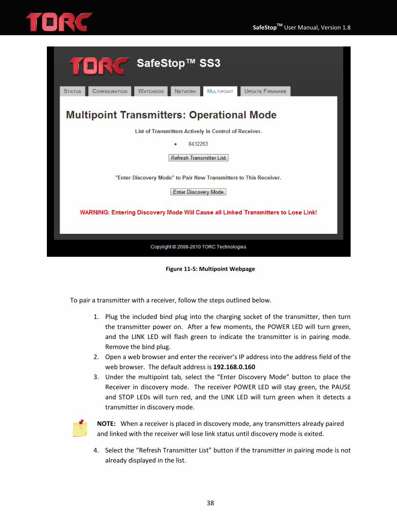
Figure 11-5: Multipoint Webpage
To pair a transmitter with a receiver, follow the steps outlined below.
1. Plug the included bind plug into the charging socket of the transmitter, then turn the transmitter power on. After a few moments, the POWER LED will turn green, and the LINK LED will flash green to indicate the transmitter is in pairing mode. Remove the bind plug.
2. Open a web browser and enter the receiver’s IP address into the address field of the web browser. The default address is 192.168.0.160
3. Under the multipoint tab, select the “Enter Discovery Mode” button to place the Receiver in discovery mode. The receiver POWER LED will stay green, the PAUSE and STOP LEDs will turn red, and the LINK LED will turn green when it detects a transmitter in discovery mode.
NOTE: When a receiver is placed in discovery mode, any transmitters already paired and linked with the receiver will lose link status until discovery mode is exited.
4. Select the “Refresh Transmitter List” button if the transmitter in pairing mode is not already displayed in the list.

SafeStopTM User Manual, Version 1.8
39
5. Select the radio button next to the transmitter to be paired. The transmitter ID can be found on the transmitter manufacturing label.
6. Select the “Add Selected Transmitter” button. 7. The web page will display “Pairing in Progress” and then “Pairing Complete”. The
PAUSE and STOP LEDs on the transmitter will turn red, indicating successful pairing. Cycle power to the transmitter to exit pairing mode on the transmitter.
8. Select the “Pair Another Transmitter” button and repeat from step 1 to add an additional transmitter.
9. To exit discovery mode on the receiver, select the “Exit Discovery Mode” to return the receiver to normal operation.
NOTE: When multiple transmitters are paired with a receiver, the receiver will maintain an active STOP or PAUSE state of any transmitters that lose link status (turned off or go out of range). To clear a STOP or PAUSE caused by link loss, an active transmitter or wired stop must explicitly indicate STOP/PAUSE and then resume.
Figure 11-6: Multipoint Discovery Webpage
SafeStopTM User Manual, Version 1.8
40
12.6 Firmware Updates The SafeStop™ system features the ability to update the firmware through a web interface. To update the firmware follow the steps outlined below.
1. Turn on the power to the SafeStop™ transmitter and receiver and connect the receiver to a computer through one of the Ethernet receptacles
2. Open a web browser and enter the receiver’s IP address into the address field of the web browser. The default address is 192.168.0.160
3. Under the firmware update tab, select the “Browse” button corresponding to the type of firmware update to be performed (Receiver primary processor, Receiver secondary processor, or Transmitter). Locate the appropriate firmware file provided by TORC and click the “Open” button.
4. Select the “Update Receiver” button to load the firmware onto the receiver, “Update Secondary” button to load the firmware onto the secondary processor, or the “Update Transmitter” button to load the firmware onto the transmitter.
5. When updating the receiver firmware, the receiver LEDs may all turn off, and any transmitters powered on will lose their link status. When updating the secondary processor, there will be a brief “stop” state, which will persist if latched. When updating the transmitter firmware, the transmitter LEDs may remain off for a few moments after the transmitter power is cycled the first time following the update.
6. When the receiver firmware has been updated successfully, the webpage will be automatically redirected to the System Configuration page. Upon a successful transmitter firmware update, a webpage will be displayed indicating that the transmitter must be reset to finalize the updating process.
7. Unless otherwise specified, firmware should always be updated on the transmitters first, followed by the receiver secondary processor, followed by the primary receiver firmware.
Warning: Updating firmware in the wrong order could cause the transmitter to become unreachable.
WARNING: Updating firmware to a SafeStop™ transmitter requires that only a single transmitter is powered on and paired with the receiver, and that a wireless link is established with the receiver. The presence of multiple paired transmitters will cause the transmitter firmware update to fail.

SafeStopTM User Manual, Version 1.8
41
Figure 11-7: Update Firmware Webpage

SafeStopTM User Manual, Version 1.8
42
12 RESTORE NETWORK AND SYSTEM DEFAULTS If it becomes necessary to restore the default network settings on the SafeStop™ receiver the user should perform the following steps.
1. Power off the receiver 2. Hold down the Bypass button while power to the receiver is switched on 3. The Bypass button should be illuminated blue 4. Continue to hold the bypass button for 10 seconds 5. After 10 seconds the Bypass button illumination will turn off 6. The receiver should now be configured to use the factory default IP network settings and
system configuration settings.

SafeStopTM User Manual, Version 1.8
43
13 SYSTEM INTEGRATION Before your SafeStop™ can be used, you need to perform the following steps: fully charge the transmitter battery, install the antennas, install the receiver cables, and verify proper system operation.
14.1 Charging the Transmitter Battery Before using the SafeStop™, the transmitter battery should be fully charged. The transmitter can be charged using the included AC adapter. To charge the battery, plug the AC power supply into the Charging Receptacle. When connected to an external power supply, the Charge Status Indicator will be orange while the battery is charging and green when the battery is fully charged. Operating the SafeStop™ system while connected to external power will not drain the battery or reduce the charge time if the power adapter is properly connected.
WARNING: Do not leave the SS03TX transmitter unattended while charging the battery.
WARNING: Only charge the battery using an approved power adapter.
14.2 Installing the Antennas Before turning the SafeStop™ transmitter or receiver on, the device antennas must be properly connected. Install the antennas by threading them clockwise onto the corresponding RP-TNC antenna connectors.
CAUTION: Do not over tighten antenna connectors.
14.3 Installing the Receiver Cables into the Vehicle System The installation of the receiver consists of properly wiring the Power cable and the Safety cable. Using the supplied power cable (P/N: SS03PWR), power the receiver using a power source (not included) capable of 8 Watts at 10-40VDC. The power cable’s (P/N: SS03PWR) red wire should be connected to the positive terminal, and the black wire should be connected to ground.
CAUTION: Connecting the receiver to a voltage outside the 10 to 40 volt range may cause the system not to function properly.
14.4 Example 5V Logic Level Wiring Schematics

SafeStopTM User Manual, Version 1.8
44
GND
SafeStop™ Receiver
VIN
Loop B
Loop A
Emergency Stop/Override Output
VehicleBattery
5.1VZener Diode
Logic Level Out
Figure 13-1: Example External 5V Logic Schematic
14.5 Example Vehicle Wiring Schematics
Vehicle Power
GND
SafeStop™ Receiver
VIN
Loop B
Loop A
Emergency Stop/Override Output
VehicleBattery
Customer Relay
2A Max
ProtectionDiode
Figure 13-2: Example External Relay Interface
WARNING: When switching inductive loads such as relays, a protection diode must be used to suppress voltage transients.

SafeStopTM User Manual, Version 1.8
45
14.6 Example External Button Wiring Schematics The button loops for both Emergency Stop and Emergency Override operate in the same manner. All buttons should be connected in series with the Loop A and Loop B pins. Normally closed buttons should be used so that when any one button is pressed (the contacts become disconnected) the output is driven low to ground.
N.C. N.C.
Customer Interface
GND
SafeStop™ Receiver
VIN
Loop B
Loop A
Emergency Stop/Override Output
VehicleBattery
Figure 13-3: External Button Schematic
14.7 Verify Operation of the System After connecting the power and safety cables to the SafeStop™ receiver, turn the power to the receiver on (the transmitter should not be powered at this time). The transmitter AC adapter uses the same pin out as the receiver power connector and is capable of powering the receiver for the initial bench test. Once power to the receiver is turned on, the status indicator lights should correspond to the table shown below.

SafeStopTM User Manual, Version 1.8
46
Operation Test: Transmitter OFF Receiver ON (receiver status indicators)
Indicator Status Meaning
Power Green Unit power is on
Link Red Communications link to transmitter has been lost Pause Red System is paused Stop Red Stop output is connected to GND Bypass Off Normal Operation
To verify the operation of the receiver and transmitter working together, turn the SafeStop™ transmitter power on while the receiver is still powered. Once power to the transmitter is turned on, the status indicators should correspond to the values shown in the table below. The Pause and Stop status indicators should depict the state of the Run/Pause toggle switch and Stop button respectively.
Operation Test: Transmitter ON Receiver ON (transmitter status indicators)
Indicator Status Meaning
Power Green Unit power is on
Link Green Communications link established Pause Green Run/Pause toggle switch is in Run position Red Run/Pause toggle switch is in Pause position Stop Green Stop button is released Red Stop button is pressed
Operation Test: Transmitter ON Receiver ON (receiver status indicators)
Indicator Status Meaning
Power Green Unit power is on
Link Green Communications link established Pause Green Run/Pause toggle switch is in Run position Red Run/Pause toggle switch is in Pause position Stop Green Stop button is released Red Stop button is pressed Bypass Off Bypass Mode not enabled
Turning off power to the receiver while the transmitter is still powered will result in a lost communications link and the status indicators should correspond to the values in the table
SafeStopTM User Manual, Version 1.8
47
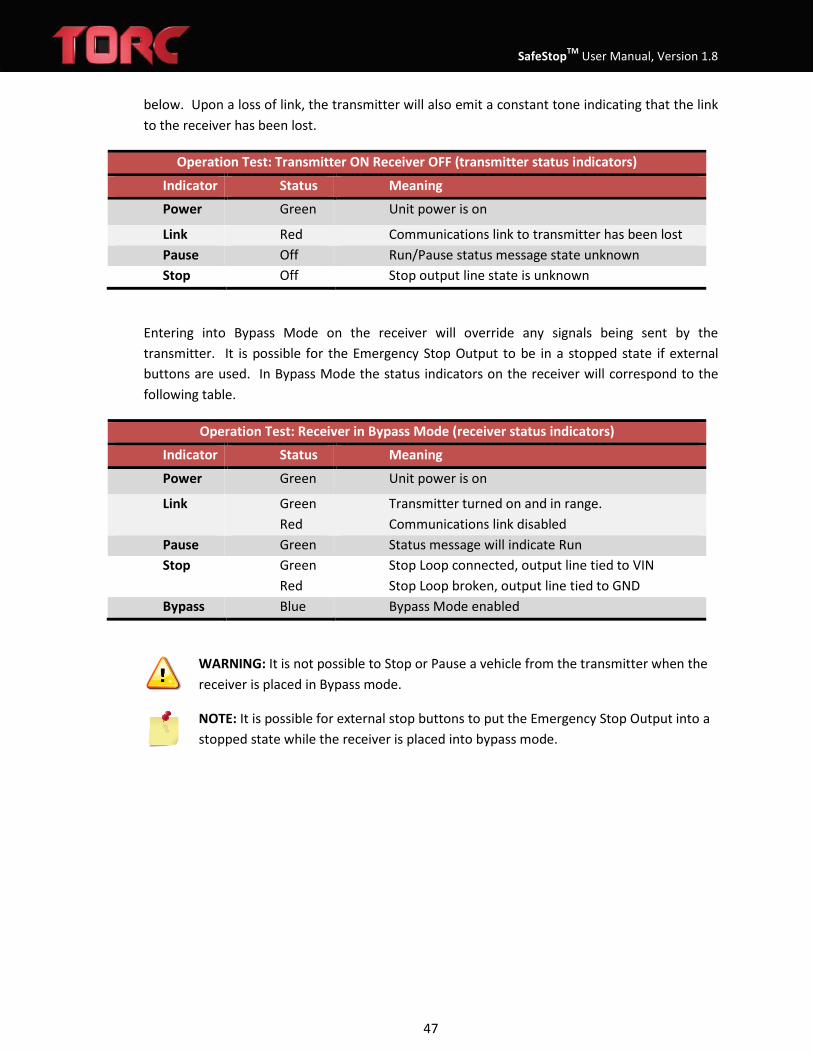
below. Upon a loss of link, the transmitter will also emit a constant tone indicating that the link to the receiver has been lost.
Operation Test: Transmitter ON Receiver OFF (transmitter status indicators)
Indicator Status Meaning
Power Green Unit power is on
Link Red Communications link to transmitter has been lost Pause Off Run/Pause status message state unknown Stop Off Stop output line state is unknown
Entering into Bypass Mode on the receiver will override any signals being sent by the transmitter. It is possible for the Emergency Stop Output to be in a stopped state if external buttons are used. In Bypass Mode the status indicators on the receiver will correspond to the following table.
Operation Test: Receiver in Bypass Mode (receiver status indicators)
Indicator Status Meaning
Power Green Unit power is on
Link Green Red
Transmitter turned on and in range. Communications link disabled
Pause Green Status message will indicate Run Stop Green Stop Loop connected, output line tied to VIN Red Stop Loop broken, output line tied to GND Bypass Blue Bypass Mode enabled
WARNING: It is not possible to Stop or Pause a vehicle from the transmitter when the receiver is placed in Bypass mode.
NOTE: It is possible for external stop buttons to put the Emergency Stop Output into a stopped state while the receiver is placed into bypass mode.
SafeStopTM User Manual, Version 1.8
48
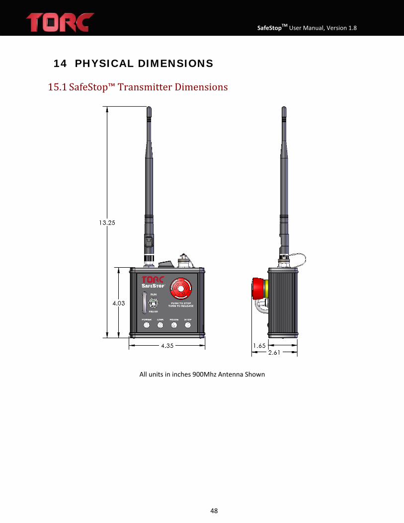
14 PHYSICAL DIMENSIONS
15.1 SafeStop™ Transmitter Dimensions
All units in inches 900Mhz Antenna Shown

SafeStopTM User Manual, Version 1.8
49
15.2 Transmitter Mount Dimensions The SafeStop™ transmitter features a standard AMPS/RAM mount hole pattern on the rear of the unit. Several mounting options are available, contact TORC for details.

SafeStopTM User Manual, Version 1.8
50
15.3 SafeStop™ OEM Transmitter Dimensions

SafeStopTM User Manual, Version 1.8
51
15.4 SafeStop™ Receiver Dimensions
All dimensions in inches
15.5 SafeStop™ Receiver Mounting Template

SafeStopTM User Manual, Version 1.8
52

SafeStopTM User Manual, Version 1.8
53
15 FCC COMPLIANCE
This equipment has been approved for mobile applications where the equipment should be used at distances greater than 20cm from the human body (with the exception of hands, wrists, feet, and ankles). Operation at distances less than 20 cm is strictly prohibited.
This device complies with Part 15 of the FCC Rules. Operation is subject to the following conditions: (1) This device may not cause harmful interference, and (2) This device must accept any interference received, including interference that may cause undesired operation.
FCC ID: KNY-42182112519
16 LIMITED WARRANTY
TORC Robotics, Inc. (herein referred to as TORC®) guarantees that the product(s) you have purchased from TORC are free from defects in materials or workmanship for a period of one year from the original date of purchase. Within this period TORC will, at its sole discretion, repair or replace any components which fail under normal use. This warranty does not cover failures due to abuse, misuse, accident, or unauthorized alterations or repairs.
There are no other warranties, expressed or implied, which extend beyond the description contained herein including the implied warranty of merchantability and fitness for a particular purpose. TORC expressly excludes all other warranties
TORC’s liability is limited to the cost of repair or replacement of the product. Such remedy shall be the sole and exclusive remedy for any breach of warranty.
TORC shall not be liable for:
1. Damage to other property caused by any defects in the product, damages based upon inconvenience, loss of use of the product, loss of time, loss of profits, loss of business opportunity, loss of goodwill, interference with business relationships, or other commercial loss, even if advised of the possibility of such damages.
2. Any indirect or other damages, whether incidental, consequential, or otherwise.
3. Any claim against the customer by any other party.
The SafeStop™ firmware incorporates portions of the lwIP TCP/IP networking stack, originally developed by Adam Dunkels at the Swedish Institute of Computer Science. The source code and full text of the associated license agreement may be downloaded from http://savannah.nongnu.org/projects/lwip.