4012-46TAG3A Non EC (TPD1587E-4) - AJ Powerajpower.net/all/4012-46TAG3A.pdf · 4012-46TAG3A ......
18
@Perkins Technical Data ® Basic technical data Number of cylinders . ... ... ... ... ... ... ... ... ... ... ... ... ... ... ... ... . 12 Cylinder arrangement ... ... ... ... ... ... ... ... ... ... ... ... ... ... Vee, 60° Cycle . ... ... ... ... ... ... ... ... ... ... ... ... ... ... ... ... ... ... ... ... . 4 stroke Induction system... ... ... ... ... ... ... ... ... ... ... ... ... ... Turbocharged Combustion system .. ... ... ... ... ... ... ... ... ... ... ... . direct injection Compression ratio. ... ... ... ... ... ... ... ... ... ... ... ... ... ... ... ... .. 13:1 Bore .. ... ... ... ... ... ... ... ... ... ... ... ... ... ... ... ... ... ... ... ... 160 mm Stroke .. ... ... ... ... ... ... ... ... ... ... ... ... ... ... ... ... ... ... ... 190 mm Cubic capacity .. ... ... ... ... ... ... ... ... ... ... ... ... ... ... .. 45·842 litres Direction of rotation... .. anti-clockwise when viewed from flywheel Firing order ... ... ... ... 1 A , 6 B , 5 A , 2 B , 3 A , 4 B , 6 A , 1 B , 2 A , 5 B , 4 A , 3 B Cylinder 1.. ... ... ... ... ... ... ... ... ... ... ... ... ... furthest from flywheel Note: Cylinders designated ‘A’ are on the right hand side of the engine when viewed from the flywheel end Approximate weights Overall dimensions of ElectropaK Moment of inertia Engine... ... ... ... ... ... ... ... ... ... ... ... ... ... ... ... ... ... ... . 9,73 kgm² Flywheel ... ... ... ... ... ... ... ... ... ... ... ... ... ... ... ... ... ... . 9,57 kgm² Cyclic irregularity for engine/flywheel maximum 4012-46TAG3A . ... ... ... ... ... ... ... ... ... ... ... ... ... ... ... ... ... 1:638 Ratings Steady state speed stability at constant load . ... ... ... ... .. ± 0·25% Electrical rating are based on average alternator efficiency and are for guidance only (0.8 power factor being used). Operating point Engine speed ... ... ... ... ... ... ... ... ... ... ... ... ... ... ... 1500 rev/min Static injection timing . ... ... ... ... ... ... ... see engine number plate Cooling water exit temperature .. ... ... ... ... ... ... ... ... ... ... < 98 °C Fuel data ... ... ... ... . to conform to BS2869 class A2 or BS EN590 Performance All data based on operation to ISO 3046/1, BS 5514 and DIN 6271 standard reference conditions. Noise For noise data, refer to page 16. For engines operating in ambient conditions other than the standard reference conditions stated below, a suitable de-rate must be applied. De-rate tables for increased ambient temperature and/or altitude are available, please contact Perkins Applications Department. Test conditions Air temperature. . ... ... ... ... ... ... ... ... ... ... ... ... ... ... ... ... .. 25 °C Barometric pressure ... ... ... ... ... ... ... ... ... ... ... ... ... ... ... 100 kPa Relative humidity ... ... ... ... ... ... ... ... ... ... ... ... ... ... ... ... .... 30% Air inlet restriction at maximum power (nominal) ... ... ... ... 2,5 kPa Exhaust back pressure at maximum pressure (nominal) ... 3,0 kPa Fuel temperature (inlet pump) ... ... ... ... ... ... ... .. 58 °C maximum For test conditions relevant to data on load acceptance, refer to page 16 of this document. Description unit Tropical Temperate Engine (dry) Kg 4400 4400 Electropak (wet) + fuel cooler Kg 6450 6086 Electropak (wet) - fuel cooler Kg 6425 6070 unit Tropical Temperate Height mm 2610 2259 Length mm 3883 3915 Width mm 2164 2198 4000 Series 4012-46TAG3A Diesel Engine - ElectropaK
Transcript of 4012-46TAG3A Non EC (TPD1587E-4) - AJ Powerajpower.net/all/4012-46TAG3A.pdf · 4012-46TAG3A ......
@PerkinsTechnical Data
®
4000 Series 4012-46TAG3ADiesel Engine - ElectropaK
Basic technical dataNumber of cylinders . ... ... ... ... ... ... ... ... ... ... ... ... ... ... ... ... . 12Cylinder arrangement ... ... ... ... ... ... ... ... ... ... ... ... ... ... Vee, 60°Cycle. ... ... ... ... ... ... ... ... ... ... ... ... ... ... ... ... ... ... ... ... .4 strokeInduction system... ... ... ... ... ... ... ... ... ... ... ... ... ... TurbochargedCombustion system .. ... ... ... ... ... ... ... ... ... ... ... . direct injectionCompression ratio. ... ... ... ... ... ... ... ... ... ... ... ... ... ... ... ... .. 13:1Bore .. ... ... ... ... ... ... ... ... ... ... ... ... ... ... ... ... ... ... ... ... 160 mmStroke .. ... ... ... ... ... ... ... ... ... ... ... ... ... ... ... ... ... ... ... 190 mmCubic capacity .. ... ... ... ... ... ... ... ... ... ... ... ... ... ... ..45·842 litresDirection of rotation... .. anti-clockwise when viewed from flywheelFiring order ... ... ... ... 1A, 6B, 5A, 2B, 3A, 4B, 6A, 1B, 2A, 5B, 4A, 3B
Cylinder 1.. ... ... ... ... ... ... ... ... ... ... ... ... ... furthest from flywheelNote: Cylinders designated ‘A’ are on the right hand side of the engine when viewed from the flywheel end
Approximate weights
Overall dimensions of ElectropaK
Moment of inertiaEngine... ... ... ... ... ... ... ... ... ... ... ... ... ... ... ... ... ... ... . 9,73 kgm²Flywheel ... ... ... ... ... ... ... ... ... ... ... ... ... ... ... ... ... ... . 9,57 kgm²
Cyclic irregularity for engine/flywheel maximum4012-46TAG3A. ... ... ... ... ... ... ... ... ... ... ... ... ... ... ... ... ... 1:638
RatingsSteady state speed stability at constant load . ... ... ... ... .. ± 0·25%Electrical rating are based on average alternator efficiency and are for guidance only (0.8 power factor being used).
Operating pointEngine speed ... ... ... ... ... ... ... ... ... ... ... ... ... ... ... 1500 rev/minStatic injection timing . ... ... ... ... ... ... ... see engine number plateCooling water exit temperature .. ... ... ... ... ... ... ... ... ... ... < 98 °CFuel data ... ... ... ... .to conform to BS2869 class A2 or BS EN590
PerformanceAll data based on operation to ISO 3046/1, BS 5514 and DIN 6271 standard reference conditions.
NoiseFor noise data, refer to page 16.For engines operating in ambient conditions other than the standard reference conditions stated below, a suitable de-rate must be applied. De-rate tables for increased ambient temperature and/or altitude are available, please contact Perkins Applications Department.
Test conditionsAir temperature. . ... ... ... ... ... ... ... ... ... ... ... ... ... ... ... ... .. 25 °CBarometric pressure... ... ... ... ... ... ... ... ... ... ... ... ... ... ... 100 kPaRelative humidity ... ... ... ... ... ... ... ... ... ... ... ... ... ... ... ... ... . 30%Air inlet restriction at maximum power (nominal) ... ... ... ... 2,5 kPaExhaust back pressure at maximum pressure (nominal) ... 3,0 kPaFuel temperature (inlet pump) ... ... ... ... ... ... ... .. 58 °C maximumFor test conditions relevant to data on load acceptance, refer to page 16 of this document.
Description unit Tropical Temperate
Engine (dry) Kg 4400 4400
Electropak (wet) + fuel cooler Kg 6450 6086
Electropak (wet) - fuel cooler Kg 6425 6070
unit Tropical Temperate
Height mm 2610 2259
Length mm 3883 3915
Width mm 2164 2198
General installation
4012-46TAG3A - Temperate
4012-46TAG3A - Tropical
Note: Not to be used for combined heat and power (CHP) purposes (indicative figures only). If necessary, please consult the Applications Department, Perkins Engines Company Limited, Stafford.
Rating definitions
Baseload powerUnlimited hours usage with an average load factor of 100% of the published baseload power rating.
Prime powerVariable load. Unlimited hours usage with an average load factor of 80% of the published Prime Power over each 24 hour period. A 10% overload is available for 1 hour in every 12 hours.
Standby powerLimited to 500 hours annual usage with an average load factor of 80% of the published Standby Power rating over each 24 hour period.Up to 300 hours of annual usage may be run continuously. No overload is permitted on Standby Power.
Emissions capabilityAll 4012-46TAG ratings are optimised to the ‘best fuel consumption’ and do not comply to Harmonised International Regulation Emission Limits. More information on these statements can be obtained by contacting the Applications Department at Perkins Engines Company Limited.
Designation UnitsType of operation and application
Baseload power Prime power Standby power
Gross engine power kWm 1260 1500 1643
Fan and battery charging alternator power kW 64
Nett engine power kWm 1196 1436 1579
Brake mean effective pressure (gross) kPa 2192 2610 2859
Combustion air flow at ISO conditions m³/min 115 125 135
Exhaust gas temperature (max) after turbo °C 480
Exhaust gas flow (max) at atmospheric pressure
m³/min 350
Boost pressure ratio - 3,0 3,4 3,7
Mechanical efficiency % 89 91 92
Overall thermal efficiency (nett) % 41,5 41,0 39,0
Friction power and pumping losses kWm 120
Mean piston speed m/s 9,5
Engine coolant flow l/s 1020
Typical Genset electrical output (0.8pf)kVA 1420 1705 1875
kWe 1136 1364 1500
Assumed alternator efficiency % 95
Designation UnitsType of operation and application
Baseload power Prime power Standby power
Gross engine power kWm 1260 1500 1643
Fan and battery charging alternator power kW 60
Nett engine power kWm 1200 1440 1583
Brake mean effective pressure (gross) kPa 2192 2610 2859
Combustion air flow at ISO conditions m³/min 115 125 135
Exhaust gas temperature (max) after turbo °C 480
Exhaust gas flow (max) at atmospheric pressure
m³/min 350
Boost pressure ratio - 3,0 3,4 3,7
Mechanical efficiency % 89 91 92
Overall thermal efficiency (nett) % 41,5 41,0 39,0
Friction power and pumping losses kWm 120
Mean piston speed m/s 9,5
Engine coolant flow l/s 1020
Typical Genset electrical output (0.8pf)kVA 1425 1710 1880
kWe 1140 1368 1504
Assumed alternator efficiency % 95
Energy balance
4012-46TAG3A - Temperate
4012-46TAG3A - Tropical
Note: Not to be used for combined heat and power (CHP) purposes (indicative figures only). If necessary, please consult the Applications Department, Perkins Engines Company Limited, Stafford.
Designation Units Baseload power Prime power Standby power
Energy in fuel kW 3137 3650 4100
Energy in power output (gross) kW 1260 1500 1643
Energy to cooling fan kW 64
Energy in power output (nett) kW 1196 1436 1579
Energy to exhaust kW 1010 1102 1219
Energy to coolant and oil kW 477 510 625
Energy to radiation kW 90 110 123
Energy to charge coolers kW 300 429 490
Designation Units Baseload power Prime power Standby power
Energy in fuel kW 3137 3650 4100
Energy in power output (gross) kW 1260 1500 1643
Energy to cooling fan kW 60
Energy in power output (nett) kW 1200 1440 1583
Energy to exhaust kW 1010 1102 1219
Energy to coolant and oil kW 477 510 625
Energy to radiation kW 90 110 123
Energy to charge coolers kW 300 428 490
Cooling system
Recommended coolant: 50% inhibited ethylene glycol or 50% inhibited propylene glycol and 50% clean fresh water. For combined heat and power systems (CHP) and where there is no likelihood of ambient temperature below 10 °C, then clean ‘soft’ water may be used, treated with 1% by volume of Perkins inhibitor in the cooling system. The inhibitor is available in 1 litre bottles from Perkins under part number 21825 735.Maximum pressure in crankcase water jacket ... ... ... ... .. 170 kPaMaximum top tank temperature (standby) . ... ... ... ... ... ... ... 98 °CMaximum static pressure head on pump ... ... ... ... ... ... ... ... .. 7 m
Total coolant capacityElectrounit (engine only) ... ... ... ... ... ... ... ... ... ... ... ... ... 73 litresElectropak (engine and radiator):-temperate.. ... ... ... ... ... ... ... ... ... ... ... ... ... ... ... ... ... . 207 litres-tropical .. ... ... ... ... ... ... ... ... ... ... ... ... ... ... ... ... ... ... . 210 litresMaximum permissible restriction to coolant pump flow.. ... . 20 kPaThermostat operating range... ... ... ... ... ... ... ... ... ... ... 71 - 85 °CAmbient cooling clearance (standby power) based on air temperature at fan 6 °C above ambient.Temperature rise across the engines (standby power) with inhibited coolant .. ... ... ... ... ... ... ... ... ... ... ... ... ... ... ... ... ... ... ... ... 8 °CCoolant temperature shutdown switch setting ... ... ... 101 °C risingCoolant immersion heater capacity (2 off) . ... ... ... ... 4 kWe each
RadiatorTemperateRadiator face area . ... ... ... ... ... ... ... ... ... ... ... ... ... ... ... 3,46 m²Material and number of rows:-charge air and water jacket... ... ... ... ... ... ... ... ... .copper, 4 rowsFins per inch and material:-charge air and water jacket... ... ... ... ... ... ... ... ... brass, 12 rowsWidth of matrix ... ... ... ... ... ... ... ... ... ... ... ... ... ... ... ... ... 2,10 mHeight of matrix.. ... ... ... ... ... ... ... ... ... ... ... ... ... ... ... ... 1,65 mWeight of radiator... ... ... ... ... ... ... ... ... ... ... ... ... ... ... .. 1620 kgTotal coolant capacity including engine and pipes. ... ... . 212 litresPressure cap setting (min) . ... ... ... ... ... ... ... ... ... ... ... ... 70 kPaTropicalRadiator face area . ... ... ... ... ... ... ... ... ... ... ... ... ... ... ... 4,08 m²Material and number of rows:-charge air and water jacket... ... ... ... ... ... ... ... ... .copper, 4 rowsFins per inch and material:-charge air and water jacket... ... ... ... ... ... ... ... ... brass, 12 rowsWidth of matrix ... ... ... ... ... ... ... ... ... ... ... ... ... ... ... ... ... 1,97 mHeight of matrix.. ... ... ... ... ... ... ... ... ... ... ... ... ... ... ... ... 2,07 mWeight of radiator... ... ... ... ... ... ... ... ... ... ... ... ... ... ... .. 1630 kgTotal coolant capacity including engine and pipes. ... ... . 226 litresPressure cap setting (min) . ... ... ... ... ... ... ... ... ... ... ... ... 70 kPa
Water jacket cooling dataTemperate and Tropical-coolant flow... ... ... ... ... ... ... ... ... ... ... ... ... ... ... 1020 litres/min-coolant exit temperature (max) . ... ... ... ... ... ... ... ... ... ... .. 98 °C-coolant inlet temperature (min) . ... ... ... ... ... thermostatic control-coolant inlet temperature (max) ... ... ... ... ... ... ... ... ... ... .. 90 °C
Coolant pumpSpeed. ... ... ... ... ... ... ... ... ... ... ... ... ... ... ... ... ... 1.4 x e rev/minMethod of drive .. ... ... ... ... ... ... ... ... ... ... ... ... ... ... ... ... ... gear
FanType ... ... ... ... ... ... ... ... ... ... ... ... ... ... ... ... ... ... ... ... axial flowDiameter-Temperate ... ... ... ... ... ... ... ... ... ... ... ... ... ... ... ... ... 1600 mm-Tropical . ... ... ... ... ... ... ... ... ... ... ... ... ... ... ... ... ... ... 1740 mmNumber of blades... ... ... ... ... ... ... ... ... ... ... ... ... ... ... ... ... ... 12Material .. ... ... ... ... ... ... ... ... ... ... ... ... ... ... ... ... ... .. AluminiumDrive ratio-Temperate ... ... ... ... ... ... ... ... ... ... ... ... ... ... ... ... ... ... .. 0·93:1-Tropical . ... ... ... ... ... ... ... ... ... ... ... ... ... ... ... ... ... ... ... .. 0·80:1
4012-46TAG3A - Temperate, Standby power
4012-46TAG3A - Tropical, Standby power
Lubrication systemRecommended SAE viscosity: A multigrade oil conforming to the following must be used: API CH4 15W/40.Note: For additional notes on lubricating oil specifications, please refer to the Operation and Maintenance Manual (OMM).
Lubricating oil capacity-total system capacity.. ... ... ... ... ... ... ... ... ... ... ... ... ... 177 litres-sump maximum.. ... ... ... ... ... ... ... ... ... ... ... ... ... ... ... 159 litres-sump minimum... ... ... ... ... ... ... ... ... ... ... ... ... ... ... ... 136 litres-oil temperature at normal operating conditions to bearings 105 °C
Lubrication oil pressure-at rated speed ... ... ... ... ... ... ... ... ... ... ... ... ... ... ... ... . 400 kPa-minimum at 80 °C... ... ... ... ... ... ... ... ... ... ... ... ... ... ... . 340 kPa-oil relief values open .. ... ... ... ... ... ... ... ... ... ... ... ... ... ..400 kPa-oil filter spacing .. ... ... ... ... ... ... ... ... ... ... ... ... ... ... 20 microns-sump drain plug tapping size . ... ... ... ... ... ... ... ... ... ... ... ... .. G1-oil pump speed... ... ... ... ... ... ... ... ... ... ... ... ... ... .. 2100 rev/min-method of drive .. ... ... ... ... ... ... ... ... ... ... ... ... ... ... ... ... ... gear-shutdown switch pressure setting (where fitted) .. 193 kPa fallingOil pump flow .. ... ... ... ... ... ... ... ... ... ... ... ... ... ... ...6,0 litres/sec
Normal operating anglesFront and rear.. ... ... ... ... ... ... ... ... ... ... ... ... ... ... ... ... ... ... ... 5°Side tilt. ... ... ... ... ... ... ... ... ... ... ... ... ... ... ... ... ... ... ... ... ... . 10°
Oil consumption
Electrical systemType ... ... ... ... ... ... ... ... ... ... ... ... ... ... ... ... ... .. insulated returnAlternator voltage ... ... ... ... ... ... .. 24 volts with integral regulatorAlternator output.. ... ... 40 amps output, 28 volts at 20 °C ambientStarter type.. ... ... ... ... ... ... ... ... ... ... ... ... ... ... ... ... ... ... ... axialStarter motor voltage... ... ... ... ... ... ... ... ... ... ... ... ... ... .. 24 voltsStarter motor power. ... ... ... ... ... ... ... ... ... ... ... ... ... ... ..16,4 kWNumber of teeth on flywheel ... ... ... ... ... ... ... ... ... ... ... ... ... .156Number of teeth on starter pinion ... ... ... ... ... ... ... ... ... ... ... .. 12Minimum cranking speed ... ... ... ... ... ... ... ... ... ... ... 120 rev/minPull in current of starter motor solenoid @ -25 °C max (1) ... ... ... ... ... ... ... ... 30 amps at 24 voltsHold in current of starter motorsolenoid @ -25 °C max (1) ... ... ... ... ... ... ... ... ..9 amps at 24 voltsStop solenoid hold-in current... ... ... ... ... ... .. 1,1 amps at 24 voltsEngine stop solenoid ... ... ... ... ... ... ... ... ... ... ... ... ... ... ...24 volts1. All leads to rated at 10 amps minimum
Maximum additional restriction (duct allowance) to cooling airflow
and resultant minimum airflow
Ambient clearance: 50% Glycol
Duct allowance(Pa)
Min airflow(m³/sec)
40 °C 250 32
Maximum additional restriction (duct allowance) to cooling airflow
and resultant minimum airflow
Ambient clearance: 50% Glycol
Duct allowance(Pa)
Min airflow(m³/sec)
50 °C 125 37
Prime power Units
After “running in” (typically after 250 hours)
g/kWhr 0,52
Oil flow rate from pump litres/sec 6
Fuel system
Recommended fuel to conform to:BS2869 1998 Class A2 or BS EN590Injection system . ... ... ... ... ... ... ... ... ... ... ... ... ... ... ... ... .. directFuel injection pump and injector type ... ... . combined unit injectorInjector pressure ... ... ... ... ... ... ... ... ... ... ... ... ... ... ... . 140 MPaLift pump type ... ... ... ... ... ... ... ... ... ... ... ... ... Tuthill TCH 1-089
Delivery-4012-46TAG3A. ... ... ... ... ... ... ... ... ... ... ... ... ... 1020 litres/hourHeat retained in fuel to tank ... ... ... ... ... ... ... ... ... ... ... ... ... 8 kWFuel inlet temperature to be less than ... ... ... ... ... ... ... ... .. 58 °CDelivery pressure ... ... ... ... ... ... ... ... ... ... ... ... ... ... ... .. 300 kPaMaximum suction head at pump inlet ... ... ... ... ... ... ... ... .. 2,5 mMaximum static pressure head .. ... ... ... ... ... ... ... ... ... ... ... . 3 mFuel filter spacing... ... ... ... ... ... ... ... ... ... ... ... ... ... ...10 micronsGovernor type ... ... ... ... ... ... ... ... ... ... ... ... ... ... ... ... electronicGoverning toISO 8528-12 CLASS 3 and 4; ISO 8528-5 CLASS G2Tolerance on fuel consumption.. ... ... ... ... ... ... ... ... ... ... ... .. 5%
Fuel consumption
Note: Fuel consumption calculated on gross rated powers.
Induction system
Maximum air intake restriction of engine:-clean filter... ... ... ... ... ... ... ... ... ... ... ... ... ... ... ... ... ... ... . 2 kPa-dirty filter. ... ... ... ... ... ... ... ... ... ... ... ... ... ... ... ... ... ... ... . 4 kPa-air filter type ... ... ... ... ... ... ... ... ... ... ... ... ... ... ... paper element
Exhaust system
Exhaust outlet size (internal) ... ... ... ..2 x 254 mm Table D flangesExhaust outlet flange size ... ... ... ... ..2 x 254 mm Table D flangesBack pressure for total system at standby power ... ... ... ... . 5 kPaFor recommended pipe sizes, please refer to the Installation Manual.
Cold start recommendations
Notes:
� The battery capacity is defined by the 20 hour rate
� The oil specification should be for the minimum ambient temperature as the oil will not be warmed by the immersion heater
� Breakaway current is dependant on battery capacity available. Cables should be capable of handling the transient current which may be up to double the steady cranking current.
Engine mounting
Maximum static bending moment at rear face of block ... 1356 NmMaximum additional load applied to flywheeldue to all rotating components ... ... ... ... ... ... ... ... ... ... ... 850 kg
Centre of gravity
Bare engine, dry-forward of the rear face of the cylinder block . ... ... ... ... . 771 mm-above the crankshaft centre line ... ... ... ... ... ... ... ... ... ... 32 mmElectropaK, dry-forward of the rear face of the cylinder block . ... ... ... ... 1176 mm-above the crankshaft centre line ... ... ... ... ... ... ... ... ... ... 32 mm
Ratings g/kW/hr litres/hr
4012-46TAG3A, Temperate & Tropical
Standby 211 405
Prime 208 370
Baseload 207 310
75% Prime 206 275
50% Prime 202 187
Temperature range
5 °C down to -10 °C
(41 °F to 14 °F)
Oil: 15W40 CH4Starter: 2 x 24 voltsBattery: 4 x 12V 286 AhMax breakaway current: 1600 ampsCranking current: 810 ampsAids: block heatersMin mean cranking speed:120 rev/min
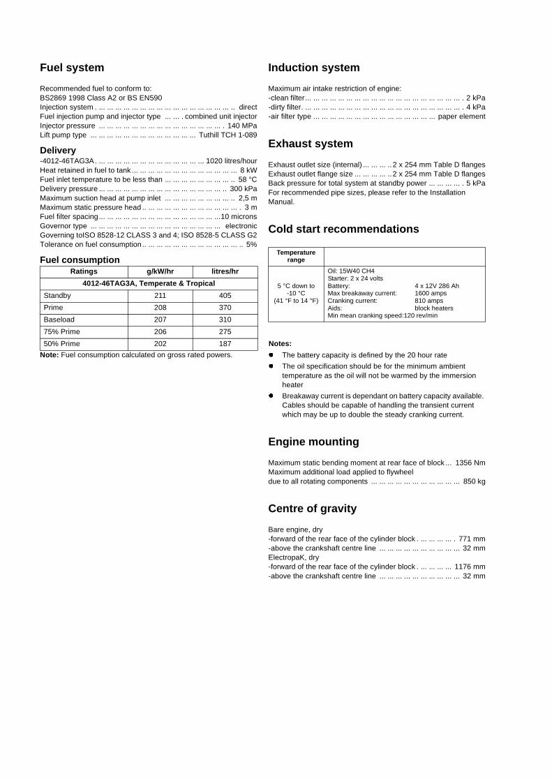
4012-46TAG3A Temperate - Left hand side view
FU
EL
LEA
K-O
FF
CO
NN
.N
O F
UE
L C
OO
LER
FIT
TE
D73
,5
391
19
189
25
585
557
1280
631
2236
3915
OV
ER
ALL
LE
NG
TH
1618
533
LUB
.OIL
FIL
LER
LUB
.OIL
DIP
ST
ICK
(BO
TH
SID
ES
)
LUB
.OIL
CO
OLE
R1
EA
CH
SID
E
RE
AR
LIF
TIN
G B
RA
CK
ET
(EN
GIN
E O
NLY
)1
EA
CH
SID
E
FU
EL
LEA
K-O
FF
CO
NN
EC
TIO
N.
EX
HA
US
T O
UT
LET
ELB
OW
1 E
AC
H S
IDE
-SE
E F
LAN
GE
DE
TA
IL.
SY
ST
EM
PIP
EW
OR
K M
US
T B
EA
DE
QU
AT
ELY
SU
PP
OR
TE
D T
O
EN
SU
RE
TH
AT
NO
LO
AD
ISE
XE
RT
ED
ON
TU
RB
OC
HA
RG
ER
S
CR
AN
KS
HA
FT
PU
LLE
Y 5
GR
OO
VE
FO
R S
PB
& B
SE
CT
ION
BE
LTS
TO
BS
379
0 : 1
995
LUB
.OIL
TE
MP
CO
NN
EC
TIO
N
PU
LLE
YG
RO
OV
EC
RS
OIL
CO
OLE
R D
RA
IN T
AP
1 E
AC
H S
IDE
CR
AN
KC
AS
E IN
SP
EC
TIO
N C
OV
ER
S
FRONT FACE C/CASE
REAR FACE C/CASE
REAR FACE FLYWHEEL HSG.
FR
ON
T G
RO
OV
E IN
PU
LLE
Y
FA
N
CR
AN
KS
HA
FT
LOW
OIL
PR
ES
SU
RE
SW
ITC
H1
EA
CH
SID
E
LUB
.OIL
PR
ES
S C
ON
NE
CT
ION
.
.
AIR
FIL
TE
RIN
LET
1 E
AC
H S
IDE
.
.
.
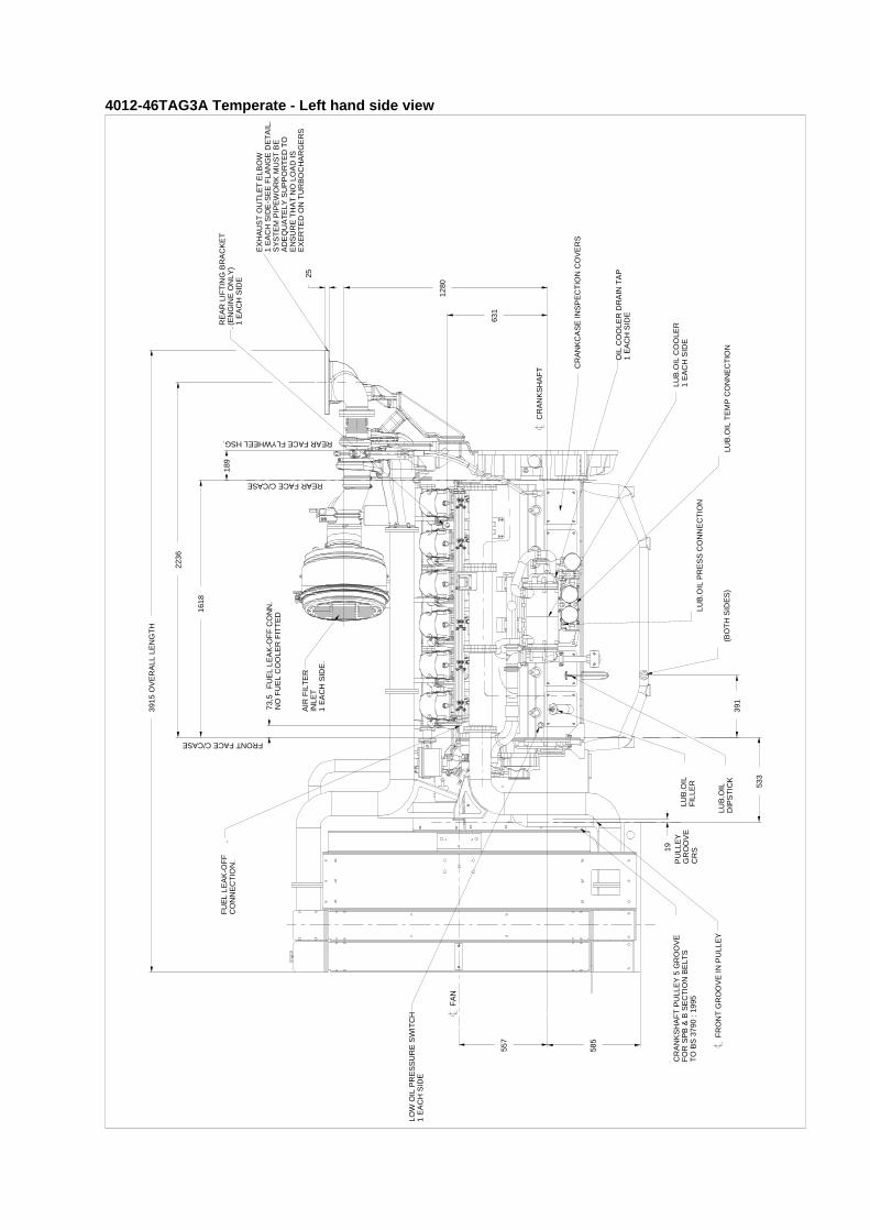
4012-46TAG3A Temperate - Front view
513
FU
EL
CO
OLE
RC
ON
NE
CT
ION
.
522
513
570
70
CR
S21
60
392
6 P
ITC
HE
SO
F 2
50
1500
641
1056
75
315
315
385
385 10
311
2112
OV
ER
MA
TR
IX
OV
ER
MA
TR
IX
1662
FU
EL
FIL
TE
R/W
AT
ER
SE
PA
RA
TO
R
TH
ER
MO
ST
AT
HO
US
ING
.
ELE
CT
RO
NIC
AC
TU
AT
OR
TH
ER
MO
ST
AT
HO
US
ING
.
CR
AN
KS
HA
FT
TH
ER
MO
ST
AT
HO
US
ING
1 E
AC
H S
IDE
.
CLE
AR
AN
CE
RE
QU
IRE
DT
O R
EM
OV
ES
UM
P.
CRANKSHAFT
RA
DIA
TO
R F
ILLE
R0.
7 B
AR
RE
LIE
F V
ALV
E.
RA
DIA
TO
R D
RA
IN
CO
ND
EN
SA
GE
DR
AIN
PLU
G W
ITH
3m
mH
OLE
TH
RO
.IN B
OT
TO
M O
F A
IR T
AN
K.
20 H
OLE
FR
ON
TLI
FT
ING
BR
AC
KE
T(E
NG
INE
ON
LY)
1 E
AC
H S
IDE
.
FU
EL
LEA
K -
OF
F C
ON
NE
CT
ION
TO
SU
IT 1
5mm
O/D
PIP
EB
ITE
TY
PE
-NO
N R
ET
UR
NV
ALV
E S
UP
PLI
ED
1 E
AC
H S
IDE
-N
O F
UE
L C
OO
LER
.F
UE
L IN
LET
CO
NN
EC
TIO
N
15(O
UT
SID
E S
TE
EL
PIP
E)
MA
XIM
UM
FU
EL
LIF
T 2
.5 M
ET
RE
SW
HE
N F
UE
L T
AN
K O
UT
LET
ISLO
WE
R T
HA
N L
IFT
PU
MP
INLE
T A
NO
N R
ET
UR
N V
ALV
E M
US
T B
EF
ITT
ED
AT
FU
EL
TA
NK
. IF
MA
XF
UE
L F
IGU
RE
IS E
XC
EE
DE
DC
ON
SU
LT P
ER
KIN
S T
EC
HN
ICA
L D
EP
T.
14 S
LOT
S 1
9 W
IDE
x 1
1 H
IGH
(FO
R D
UC
TIN
G P
UR
PO
SE
S)
FU
EL
CO
OLE
R W
HE
N F
ITT
ED
TO
RS
ION
AL
VIB
RA
TIO
N D
AM
PE
RS
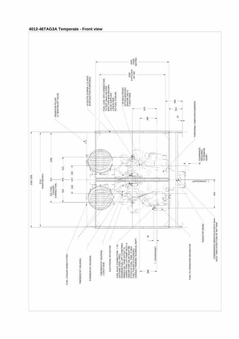
4012-46TAG3A Temperate - Right hand side view
A
1851
CE
NT
RE
OF
GR
AV
ITY
WE
T W
ITH
FU
EL
CO
OLE
R.
571
614
12 F
RO
NT
LIF
TIN
G B
RA
CK
ET
.
1310
245
1031
97
0
CR
AN
KS
HA
FT
FRONT FACE C/CASE
AIR
FLO
W
G3/
4 F
UE
L C
OO
LER
CO
NN
EC
TIO
NS
.
1854
CE
NT
RE
OF
GR
AV
ITY
WE
T N
O F
UE
L C
OO
LER
.
.
AIR
FIL
TE
R1
EA
CH
SID
EE
LEC
TR
ON
IC C
ON
TR
OL
UN
IT F
OR
AC
TU
AT
OR
LUB
OIL
FIL
TE
RS
3 E
AC
H S
IDE
DU
AL
24V
ST
AR
TE
RS
G1/
4 T
AP
PIN
G F
OR
LUB
OIL
PR
ES
SU
RS
CO
NE
CT
ION
ST
AR
TE
R R
ELA
Y
RA
DIA
TO
R W
AT
ER
LEV
EL
SW
ITC
H.
CR
AN
KC
AS
E B
RE
AT
HE
R 1
EA
CH
SID
ES
UP
PLI
ED
WIT
H F
LEX
IBLE
PIP
E
51 IN
SID
E x
865
LO
NG
.
EX
HA
US
T G
AS
HIG
H T
EM
PP
RO
TE
CT
ION
MO
DU
LE1
EA
CH
SID
E
H.W
.T P
RO
TE
CT
ION
SW
ITC
H1
EA
CH
SID
E
LUB
-OIL
TE
MP
ER
AT
UR
EC
ON
NE
CT
ION
FU
EL
HA
ND
PR
IMIN
G P
UM
P
24V
ALT
ER
NA
TO
R
LUB
E O
IL P
UM
P
FU
EL
LIF
T P
UM
P
4012-46TA
G3A
Tem
perate - R
ear view
646
280
39
2259OVERALL HEIGHT
CRANKSHAFT
IRED TOER
REAR LIFTINGBRACKET
301 301235,4
1400
11.25
182 182
2198
12,512,5 464 464
SUMP DRAIN PLUG
16 HOLES M12 X 21 DEEPEQUALLY SPACED AS SHOWN ON
6 HOLES M16 X 30 DEEPEQUALLY SPACED ON
(ENGINE FEET)
24V AIR SHUT-OFF VALVEENERGISED TO CLOSE1 EACH SIDE
AIR FILTER RESTRICTIONINDICATOR - 1 EACH SIDE
CR
AN
KS
HA
FT
CLEARANCE REQUREMOVE FUEL FILT
.
4012-46TAG3A Temperate - Plan view of support pads, exhaust outlet flange and flywheel
100.035 100.000
498 571,5571,6
592 787,40
787,65 883
10
15.7
250406
22,5
6.5
DETAIL OF SAE 518 FLYWHEEL
AND SAE 00 FLYWHEEL HOUSING
(METRIC TAPPINGS)
SCALE 1:5
CRANKSHAFT
DETAIL OF EXHAUST OUTLET FLANGE
(B.S.10 TABLE D)
SCALE 1:5
8 HOLES 22EQUALLY SPACEDON 356 PC
175.5
4
154
70
60
91
435
1744
112.5
98
451
135
221
1004
300 30052100
120
945
500
1000 2008
758
6-HOLES 22
8 HOLES 22
RE
AR
FA
CE
FLY
WH
EE
L H
SG
FR
ON
T F
AC
E C
/CA
SE
LC CRANKSHAFT
4012-46TA
G3A
Tro
pical - L
eft han
d sid
e view
1280
631
OVERALL LENGTH3883
25
189
RE
AR
FA
CE
C/C
AS
E
RE
AR
FA
CE
FLY
WH
EE
L H
SG
.
CRANKSHAFT
CRANKCASE INSPECTION COVERS
OIL COOLER DRAINTAP 1 EACH SIDE
LUB OIL COOLER1 EACH SIDE
EXHAUST OUTLET ELBOW1 EACH SIDE.SEE FLANGE DETAIL.SYSTEM PIPEWORK MUST BE ADEQUATELY SUPPORTED TOENSURE THAT NO LOAD ISEXERTED ON TURBOCHARGERS
LIFTING BRACKET(ENGINE ONLY)1 EACH SIDE
OIL TEMP CONNECTION
G 1/4 TAPPING FORLUB,OIL PRESSCONNECTION
TICK
557
785.5
533
GROOVECRS
19
1336
1618
2236
786
FUEL LEAK OFFCONN NO FUELCOOLER FITTED
73,5
REF1444
391
FR
ON
T F
AC
E C
/CA
SE
FAN
FRONT GROOVE IN PULLEY
LOW OIL PRESSURESWITCH, 1 EACH SIDE.
AIR FILTER INLET1 EACH SIDE
LUB.OIL FILLER
LUB OIL DIPS
(BOTH SIDES)
FUEL LEAK OFFCONNECTION
CRANKSHAFT PULLEY 5 GROOVEFOR SPB & SECTION BELTSTO BS3790: 1995
4012-46TAG3A Tropical - Front view
513
522
641
1037
OV
ER
MA
TR
IX20
74
862
513
570
701065
315
315
385
75
CR
S21
30
10311.
535
2.5
120
4 P
ITC
HE
S@
232
.5
930
4 P
ITC
HE
S@
232
.5
930
OV
ER
MA
TR
IX
2062
TH
ER
MO
ST
AT
\HO
US
ING
ELE
CT
RO
NIC
AC
TU
AT
OR
TH
ER
MO
ST
AT
HO
US
ING
CR
AN
KS
HA
FT
TH
ER
MO
ST
AT
HO
US
ING
1 E
AC
H S
IDE
.
CRANKSHAFT
20 H
OLE
FR
ON
T L
IFT
ING
BR
AC
KE
TB
RA
CK
ET
(E
NG
INE
ON
LY)
1 E
AC
H S
IDE
FU
EL
INLE
T C
ON
NE
CT
ION
1
5(O
UT
SID
E S
TE
EL
PIP
E)
MA
XIM
UM
FU
EL
LIF
T 2
.5 M
ET
RE
SW
HE
N F
UE
L T
AN
K O
UT
LET
IS
LOW
ER
TH
AN
LIF
T P
UM
P IN
LET
,A
NO
N R
ET
UR
N V
ALV
E M
US
T B
EF
ITT
ED
AT
FU
EL
TA
NK
. IF
MA
XF
UE
L LI
FT
FIG
UR
E IS
EX
CE
ED
ED
CO
NS
ULT
PE
RK
INS
TE
CH
NO
LOG
Y D
EP
T
FU
EL
LEA
K-O
FF
CO
NN
EC
TIO
N.
TO
SU
IT 1
5mm
O/D
PIP
E.
`BIT
E`
TY
PE
NO
N-R
ET
UR
NV
ALV
E S
UP
PLI
ED
.1
EA
CH
SID
E
CLE
AR
AN
CE
RE
QU
IRE
D
TO
RE
MO
VE
SU
MP
.
CO
ND
EN
SA
TIO
N D
RA
IN P
LUG
(WIT
H 3
mm
HO
LE T
HR
O)
IN B
OT
TO
M O
F A
IR T
AN
K
RA
DIA
TO
R F
ILLE
R0.
7 B
AR
RE
LIE
F V
ALV
E
16 S
LOT
S 1
1 x
19(F
OR
DU
CT
ING
PU
RP
OS
ES
)
FU
EL
FIL
TE
R/
WA
TE
R S
EP
AR
AT
OR
TO
RS
ION
AL
VIB
RA
TIO
ND
AM
PE
RS
.
4012-46TA
G3A
Tro
pical - R
igh
t han
d sid
e view
1056
245
85
AIR FLOW
N
H.W.T PROTECTION SWITCH1 EACH SIDE
24 V ALTERNATOR
RADIATOR WATERLEVEL SWITCH
CRANKCASE BREATHER 1 EACH SIDESUPPLIED WITH FLEXIBLE PIPE
51 INSIDE X 865 LG
619
5751310
50
CENTRE OF GRAVITYWET WITH FUEL COOLER
1964
1969 CENTRE OF GRAVITYWET NO FUEL COOLER
FRONTLIFTINGBRACKET
12
36 LEAK OFFCONN NO FUELCOOLER FITTED
LUB OIL FILTERS3 EACH SIDE
STARTER RELAY
AIR FILTER1 EACH SIDE
CRANKSHAFT
ELECTRONIC CONTROLUNIT FOR ACTUATION
FR
ON
T F
AC
E C
/CA
SE
.
CONNECTIO
FUEL HANDPRIMING PUMP
FUEL LIFT PUMP
FUEL INLETCONNECTION
LUB OIL PUMP
LUB OIL PRESS CONNECTION
LUB,OIL TEMP CONNECTION
DUAL 24V STARTERS
EXHAUST GAS HIGH TEMPPROTECTION MODULE1 EACH SIDE

4012-46TA
G3A
Tro
pical - R
ear view
646
280
39
1609
2610 OVERALL
HEIGHT
2584
A BANKB BANK
CRANKSHAFT
REAR LIFTINGBRACKET
CLEARANCE REQUIRED TO REMOVE FUEL FILTER
301 301
ENGINEFEET.
235,4
1400
611
11.25
182 182
464 464
12,512.5
2164 OVERALL WIDTH
25
1280
SUMP DRAIN PLUG
16 HOLES M12 X 21 DEEPEQUALLY SPACED AS SHOWNON
6 HOLES M16 X 30 DEEPEQUALLY SPACED ON
24V AIR SHUT-OFF VALVEENERGISED TO CLOSE.1 EACH SIDE
AIR FILTER RESTRICTIONINDICATOR. 1 EACH SIDE
.

4012-46TAG3A Tropical - Plan view of support pads, exhaust outlet flange and flywheel
100.035 100.000
498 571,5571,6
592 787,40
787,65
883
10
15.7
250406
22,5
DETAIL OF SAE 518 FLYWHEEL
AND SAE 00 FLYWHEEL HOUSING
(METRIC TAPPINGS)
SCALE 1:5
CRANKSHAFT
DETAIL OF EXHAUST OUTLET FLANGE
(B.S.10 TABLE D)
SCALE 1:5
8 HOLES 22EQUALLY SPACEDON 356 PC
175.5
4
154
70
60
91
435
1744
112.5
98
451
135
221
985
300 300
52100
118
942
500
1000 1970
613.5
REF1326
8 HOLES 22
RE
AR
FA
CE
FLY
WH
EE
L H
GS
PLAN VIEW OF SUPPORT PADS
FR
ON
T F
AC
E C
/CA
SE
LCCRANKSHAFT
6 HOLES 22
1
2
3
45
6
7
8
Fan
Pa Ambient noise level 79 dBA
Noise Levels
Total Noise Level
The figures for total noise levels are typical for an engine running atStandby Power rating in a semi-reverberant environment andmeasured at a distance of one metre from the periphery of theengine.
Sound pressure level re: -20x10
Octave analysis performed at the position of maximum noise.
ENGINE 1500 RPM POWER STANDBY1/3 (1/1 bandwidth)OCTAVE ANALYSIS
SITEPOSN. DBA HZ DB AT POSN …6…
1 114 31.5 90.22 113 63 1013 111 125 1044 110 250 1125 110.5 500 1096 111 1k 1077 110.5 2k 1048 107 4k 101
8k 100
16k 98POSN. DBA HZ DB AT POSN …6…
1 114 31.5 90.92 113 63 1013 111 125 1044 110 250 1105 110 500 1096 111 1k 1067 110 2k 1038 107 4k 100
8k 9916k 98
POSN. DBA HZ DB AT POSN …6…1 114 31.5 912 113 63 1013 111 125 1044 110 250 1105 110 500 1096 111 1k 1067 110 2k 1038 107 4k 100
8k 9916k 98
AMBIENT NOISE…79……….DBA
Typical load acceptance (cold)
The above figures were obtained under test conditions as follows:Engine block temperature .. ... ... ... ... ... ... ... ... ... ... ... ... ... ... ... ... ... ... ... ... ... ... ... ... ... ... ... ... ... ... ... ... ... ... ... ... ... ... ... ... . 40 °CAmbient temperature . ... ... ... ... ... ... ... ... ... ... ... ... ... ... ... ... ... ... ... ... ... ... ... ... ... ... ... ... ... ... ... ... ... ... ... ... ... ... ... ... ... ... . 25 °CGoverning mode ... ... ... ... ... ... ... ... ... ... ... ... ... ... ... ... ... ... ... ... ... ... ... ... ... ... ... ... ... ... ... ... ... ... ... ... ... ... ... ... ... .. IsochronousAlternator inertia. ... ... ... ... ... ... ... ... ... ... ... ... ... ... ... ... ... ... ... ... ... ... ... ... ... ... ... ... ... ... ... ... ... ... ... ... ... ... ... ... ... ... ... . 50 kgm²Under frequency roll off (UFRO) point set to ... ... ... ... ... ... ... ... ... ... ... ... ... ... ... ... ... ... ... ... ... ... ... ... ... ... ... ... ... ... ... ... ... ... 49,5UFRO rate set to ... ... ... ... ... ... ... ... ... ... ... ... ... ... ... ... ... ... ... ... ... ... ... ... ... ... ... ... ... ... ... ... ... ... ... ... ... ... ... ... ... ... ... .. 16 v/hzLAM on / off ... ... ... ... ... ... ... ... ... ... ... ... ... ... ... ... ... ... ... ... ... ... ... ... ... ... ... ... ... ... ... ... ... ... ... ... ... ... ... ... ... ... ... ... ... ... ... .. onAll tests were conducted using an engine installed and serviced to Perkins Engines Company Limited recommendations.Applied load is a percentage of generator electrical output efficiency as published in the general installation section of this data sheet.The information given on this Technical Data Sheet is for standard engines, and for guidance only. For ratings other than those shown contact Perkins Engines Company Limited, Stafford.
Initial load acceptance when engine reaches rated speed
(15 seconds maximum after engine starts to crank)
2nd load application immediately after engine has recovered to rated speed
(5 seconds after initial load application)
Engine typePrime
power%Load kWe
nett
Transient frequency deviation
%
Frequency recovery
time seconds
Prime power%
Load kWe nett
Transient frequency deviation
%
Frequency recovery
time seconds
4012-46TAG3A 63 860 ≤ 10 5 37 505 ≤ 10 5
4000 Series 4012-46TAG3A
ins
Eng
ines
Com
pany
Lim
ited.
All information in the document is substantially correct at the time of printing but may be subsequently altered by the company.
Distributed by@Perkins®
Pub
licat
ion
No.
TP
D15
87E
, Iss
ue 5
. Apr
il 20
08 ©
Per
k
Perkins Engines Company LimitedPeterborough PE1 5NA United KingdomTelephone +44 (0) 1733 583000Fax +44 (0) 1733 582240www.perkins.com