400-200 kV Substation Design
62
“Design of 400/220kV Sub-station” S.M. MUJUMDAR General Manager (sub-station Engineering) 27 th April 2005 Jyoti Structures Ltd., Mumbai
Transcript of 400-200 kV Substation Design
“Design of 400/220kVSub-station”
S.M. MUJUMDARGeneral Manager(sub-station Engineering)
27th April 2005 Jyoti Structures Ltd., Mumbai
Agenda
Overview of 400kV sub-station
Design Process
Design considerations
Question / Answer
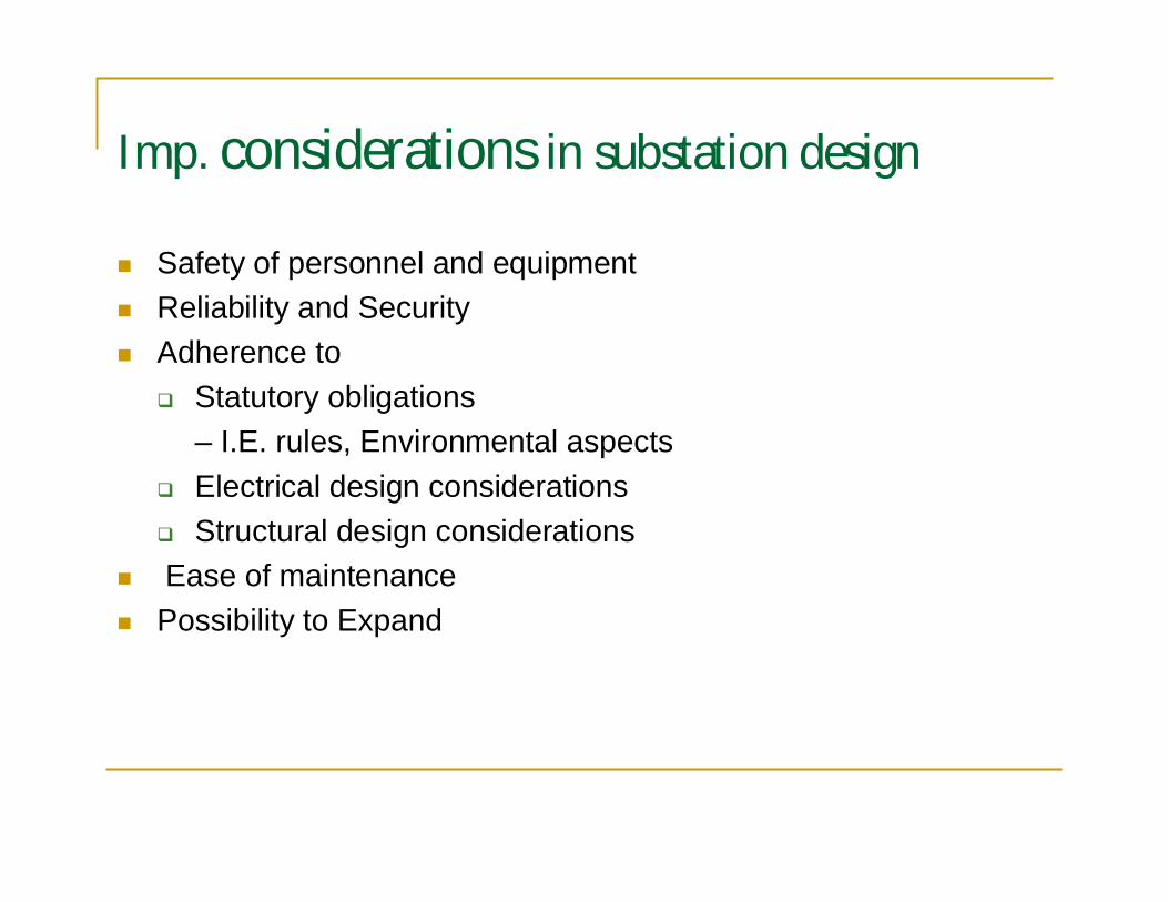
Imp. considerations in substation design
Safety of personnel and equipmentReliability and SecurityAdherence to
Statutory obligations– I.E. rules, Environmental aspectsElectrical design considerationsStructural design considerations
Ease of maintenancePossibility to Expand
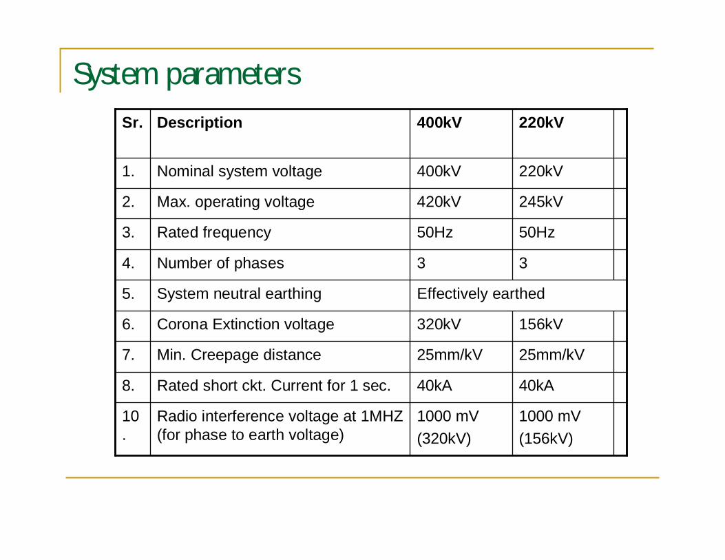
System parameters
1000 mV(156kV)
1000 mV(320kV)
Radio interference voltage at 1MHZ(for phase to earth voltage)
10.
40kA40kARated short ckt. Current for 1 sec.8.
25mm/kV25mm/kVMin. Creepage distance7.
156kV320kVCorona Extinction voltage6.
Effectively earthedSystem neutral earthing5.
33Number of phases4.
50Hz50HzRated frequency3.
245kV420kVMax. operating voltage2.
220kV400kVNominal system voltage1.
220kV400kVDescriptionSr.
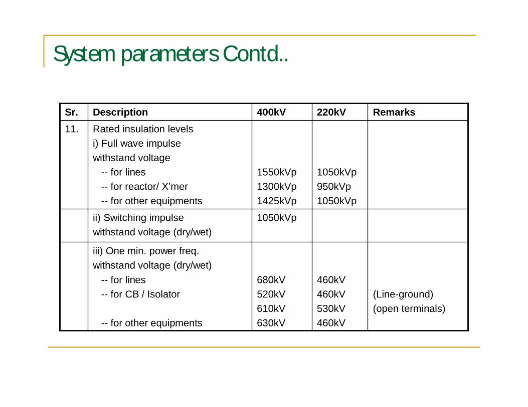
System parameters Contd..
Remarks220kV400kVDescriptionSr.
(Line-ground)(open terminals)
460kV460kV530kV460kV
680kV520kV610kV630kV
iii) One min. power freq.withstand voltage (dry/wet)
-- for lines-- for CB / Isolator
-- for other equipments
1050kVpii) Switching impulsewithstand voltage (dry/wet)
1050kVp950kVp1050kVp
1550kVp1300kVp1425kVp
Rated insulation levelsi) Full wave impulsewithstand voltage
-- for lines-- for reactor/ X’mer-- for other equipments
11.
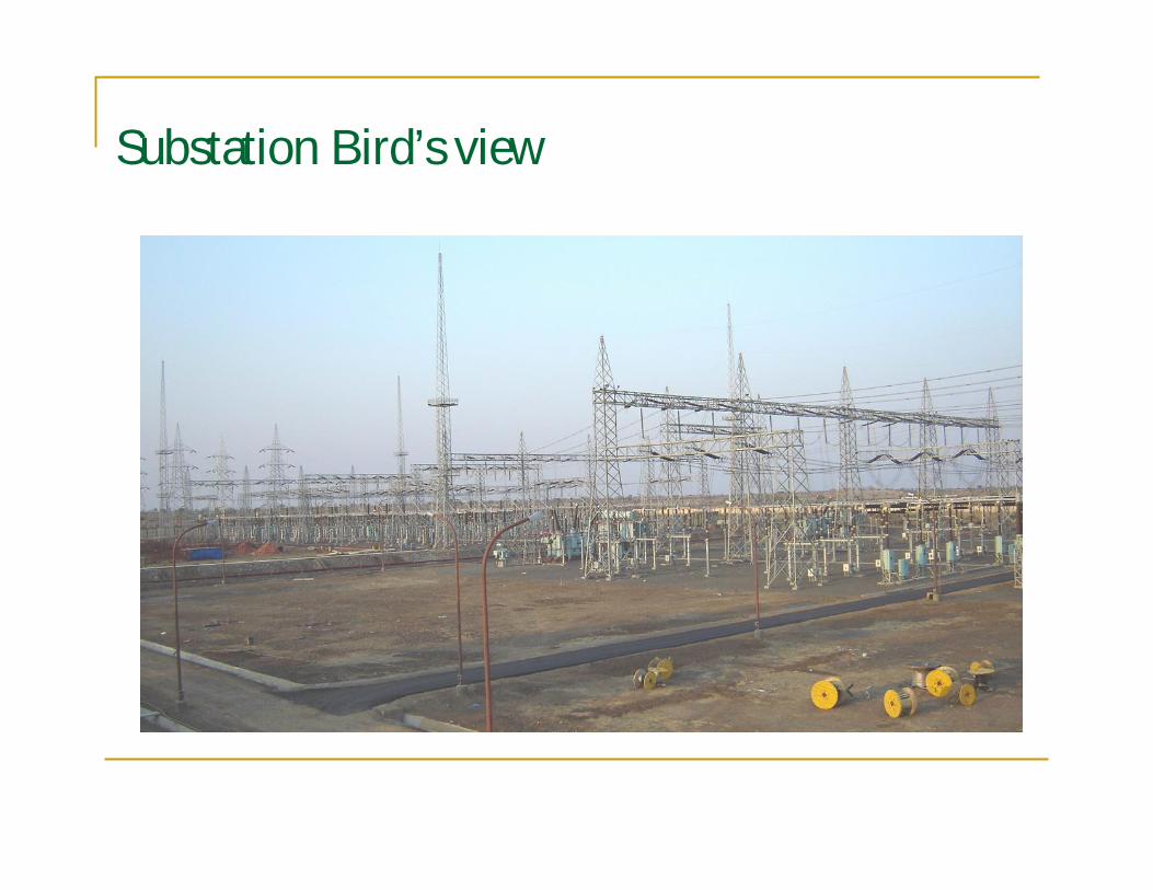
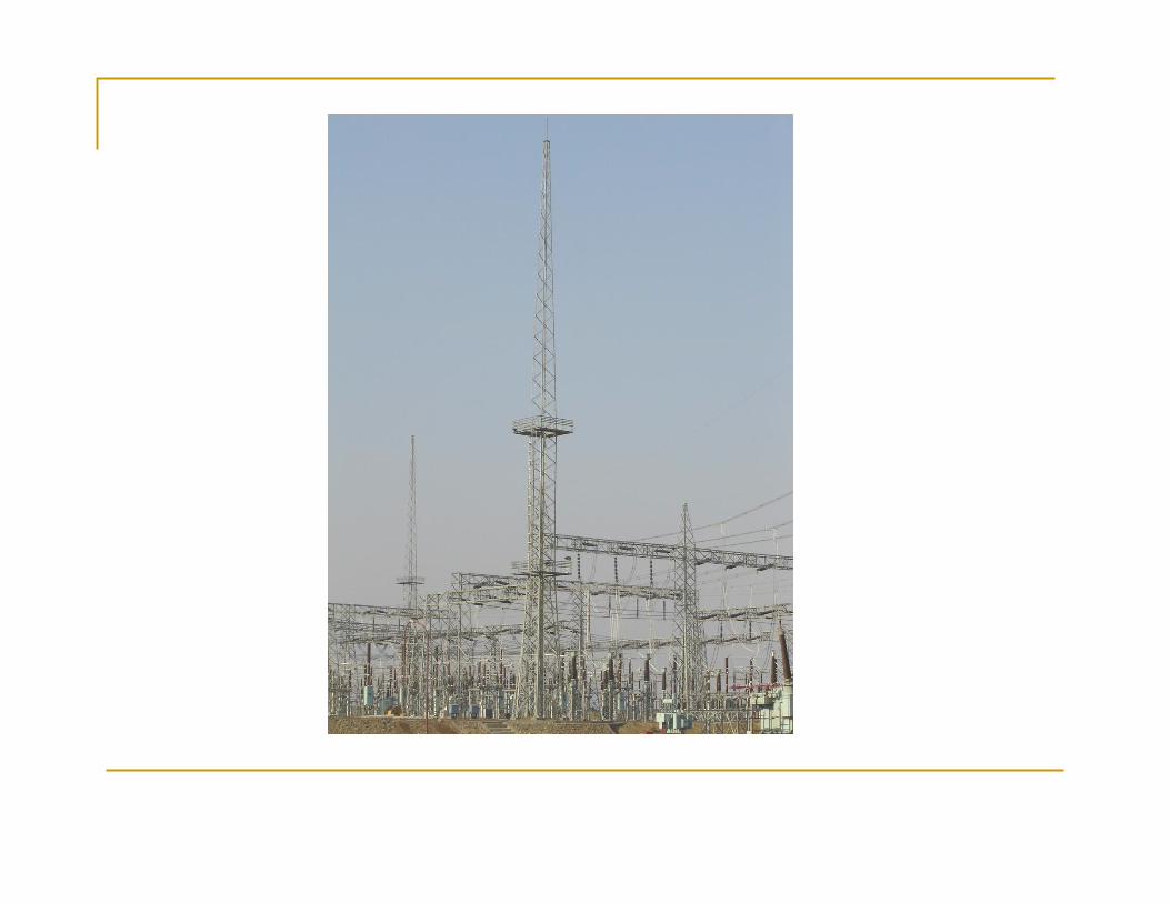
Substation Bird’s view
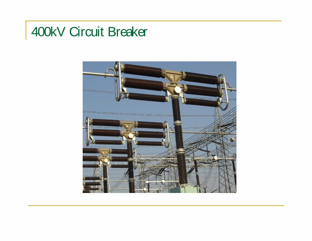
400kV Circuit Breaker
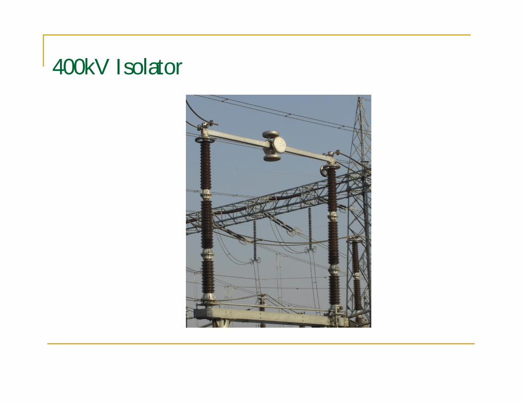
400kV Isolator
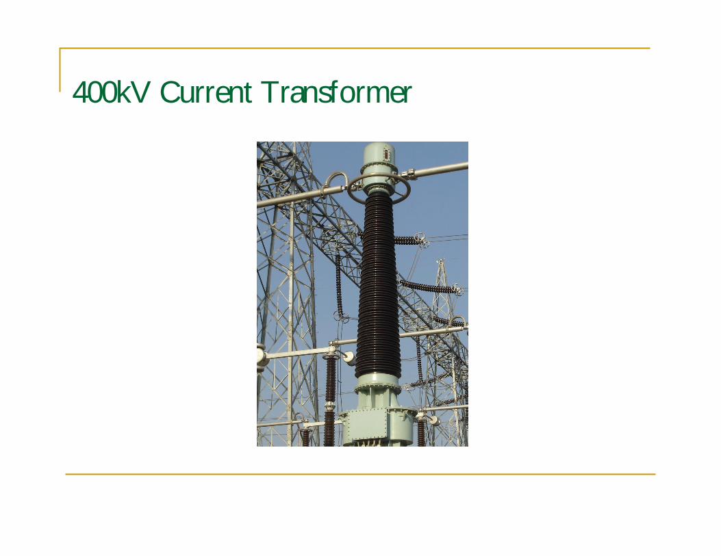
400kV Current Transformer
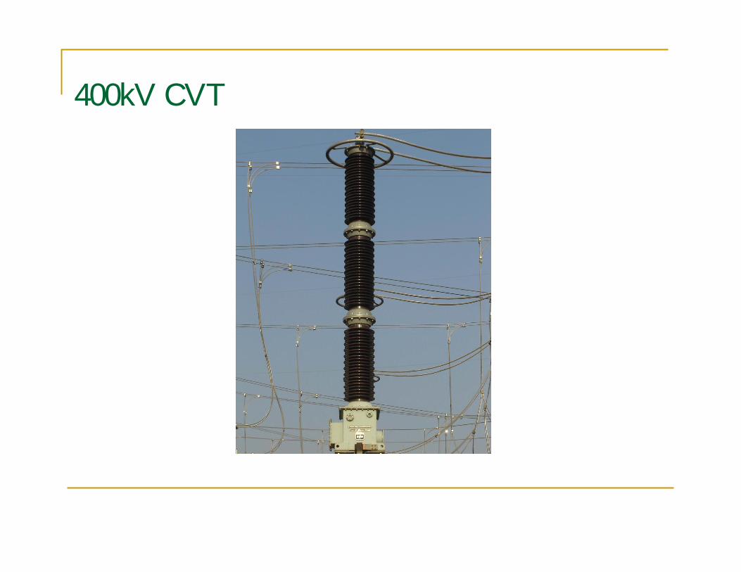
400kV CVT
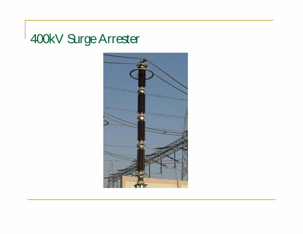
400kV Surge Arrester
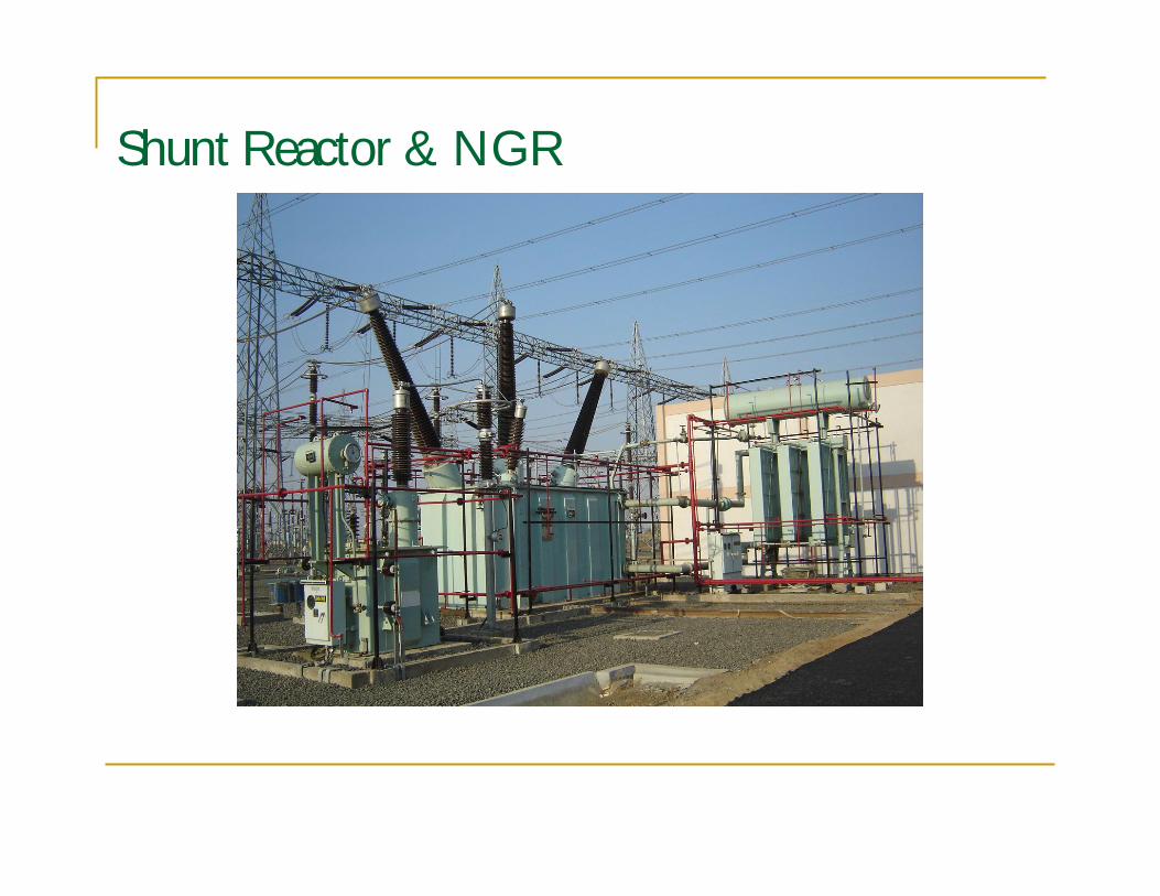
Shunt Reactor & NGR
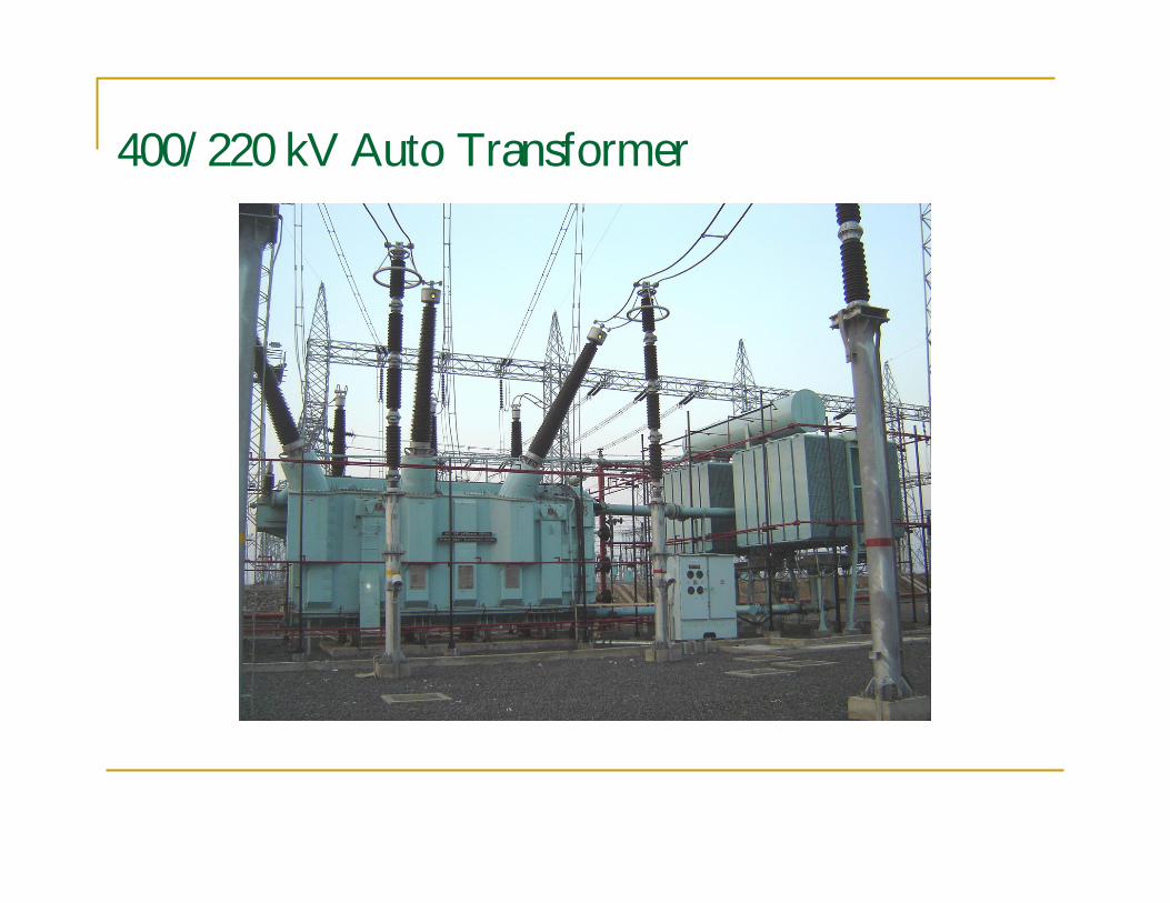
400/220 kV Auto Transformer
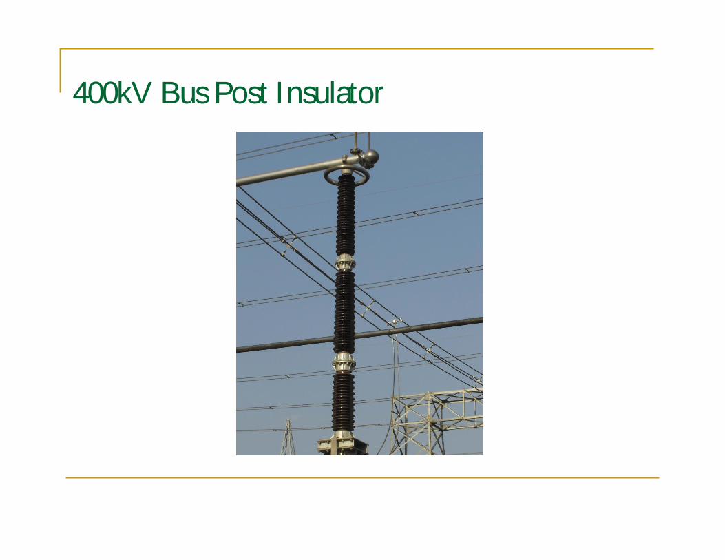
400kV Bus Post Insulator
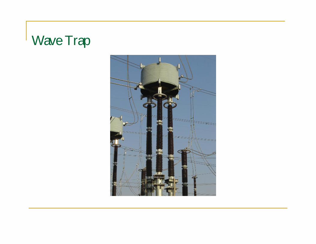
Wave Trap
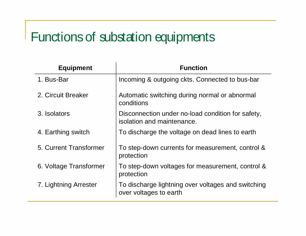
Functions of substation equipments
To discharge lightning over voltages and switchingover voltages to earth
7. Lightning Arrester
To step-down voltages for measurement, control &protection
6. Voltage Transformer
To step-down currents for measurement, control &protection
5. Current Transformer
To discharge the voltage on dead lines to earth4. Earthing switch
Disconnection under no-load condition for safety,isolation and maintenance.
3. Isolators
Automatic switching during normal or abnormalconditions
2. Circuit Breaker
Incoming & outgoing ckts. Connected to bus-bar1. Bus-Bar
FunctionEquipment
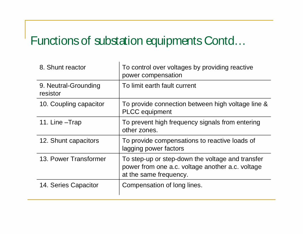
Functions of substation equipments Contd…
Compensation of long lines.14. Series Capacitor
To step-up or step-down the voltage and transferpower from one a.c. voltage another a.c. voltageat the same frequency.
13. Power Transformer
To provide compensations to reactive loads oflagging power factors
12. Shunt capacitors
To prevent high frequency signals from enteringother zones.
11. Line –Trap
To provide connection between high voltage line &PLCC equipment
10. Coupling capacitor
To limit earth fault current9. Neutral-Groundingresistor
To control over voltages by providing reactivepower compensation
8. Shunt reactor
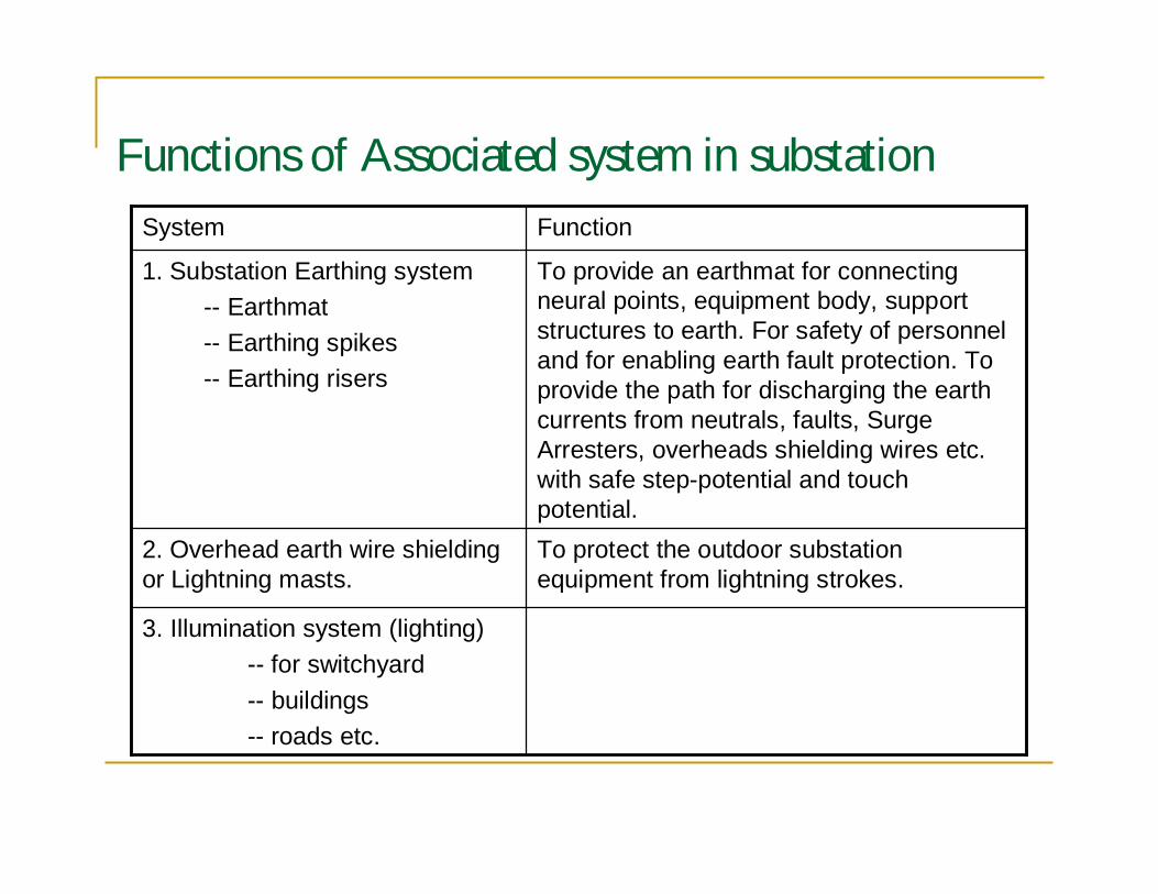
Functions of Associated system in substation
3. Illumination system (lighting)-- for switchyard-- buildings-- roads etc.
To protect the outdoor substationequipment from lightning strokes.
2. Overhead earth wire shieldingor Lightning masts.
To provide an earthmat for connectingneural points, equipment body, supportstructures to earth. For safety of personneland for enabling earth fault protection. Toprovide the path for discharging the earthcurrents from neutrals, faults, SurgeArresters, overheads shielding wires etc.with safe step-potential and touchpotential.
1. Substation Earthing system-- Earthmat-- Earthing spikes-- Earthing risers
FunctionSystem
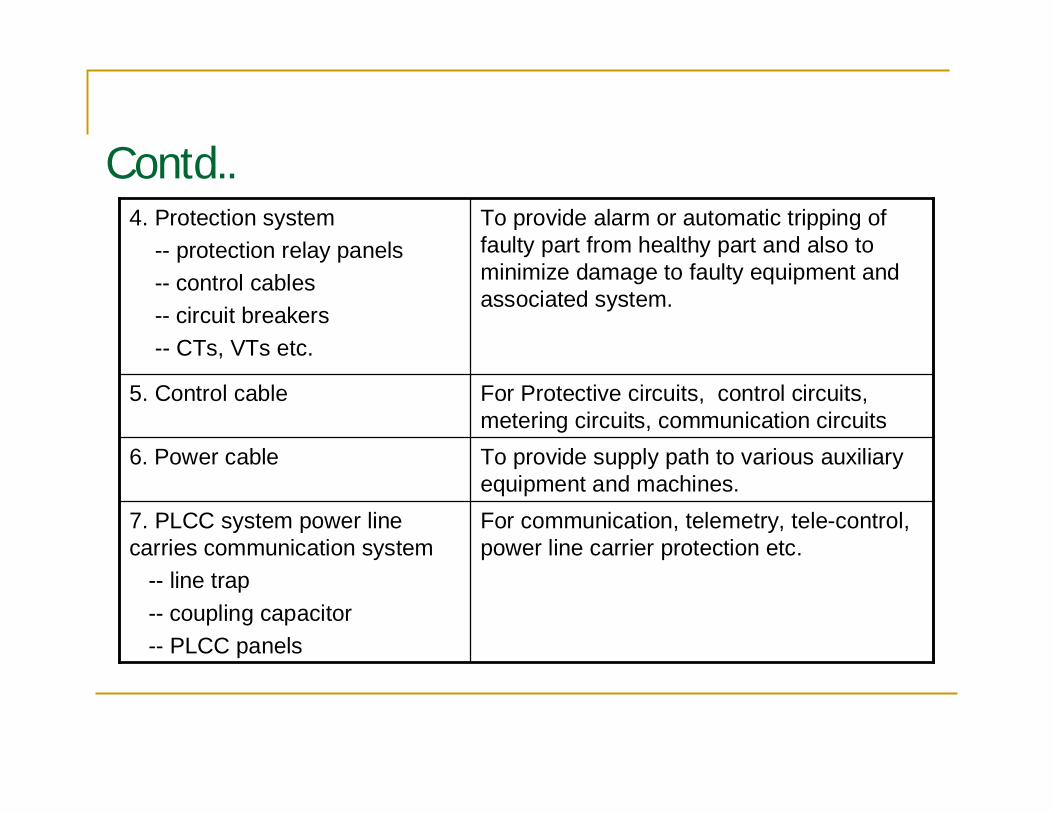
Contd..To provide alarm or automatic tripping offaulty part from healthy part and also tominimize damage to faulty equipment andassociated system.
4. Protection system-- protection relay panels-- control cables-- circuit breakers-- CTs, VTs etc.
For Protective circuits, control circuits,metering circuits, communication circuits
5. Control cable
For communication, telemetry, tele-control,power line carrier protection etc.
7. PLCC system power linecarries communication system
-- line trap-- coupling capacitor-- PLCC panels
To provide supply path to various auxiliaryequipment and machines.
6. Power cable
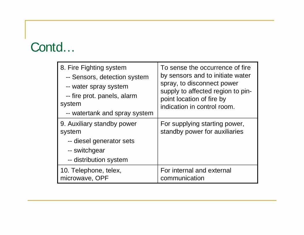
Contd…To sense the occurrence of fireby sensors and to initiate waterspray, to disconnect powersupply to affected region to pin-point location of fire byindication in control room.
8. Fire Fighting system-- Sensors, detection system-- water spray system-- fire prot. panels, alarm
system-- watertank and spray system
For internal and externalcommunication
10. Telephone, telex,microwave, OPF
For supplying starting power,standby power for auxiliaries
9. Auxiliary standby powersystem
-- diesel generator sets-- switchgear-- distribution system
Basic drawings for design/construction
Single Line Diagram
General Arrangement Drawing
Electrical Plan and Section
Control Room Architectural layout
Supporting drawings
Structural layout
Earthmat layout
Civil layout
Erection Key Diagram
Lighting Layout
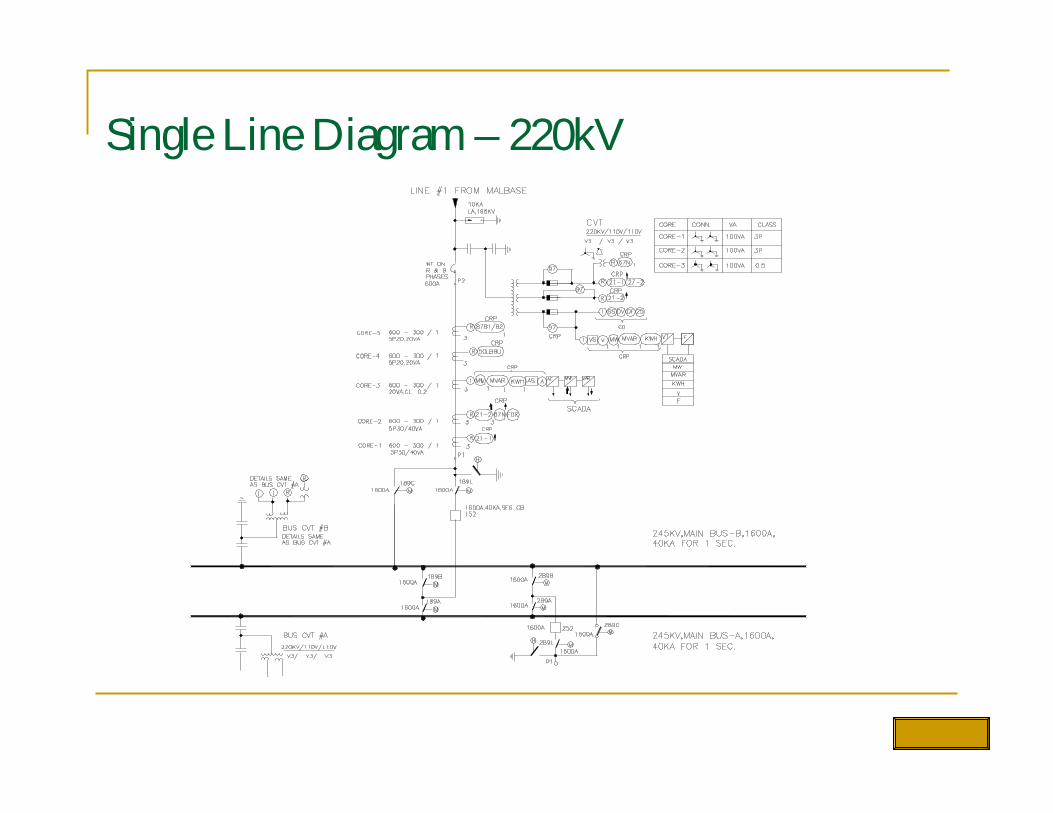
Single Line Diagram – 220kV
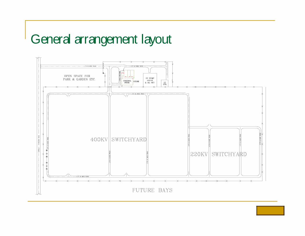
General arrangement layout
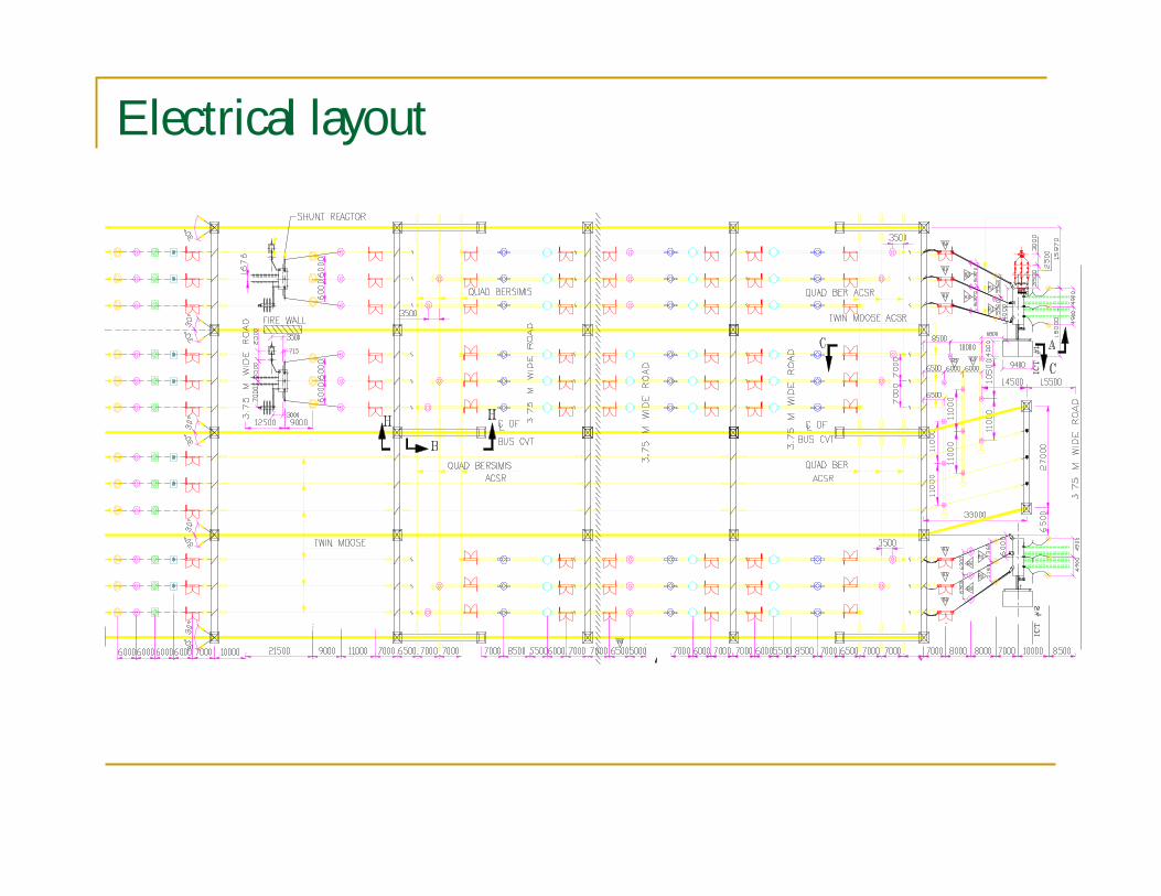
Electrical layout
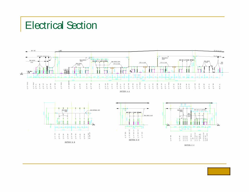
Electrical Section
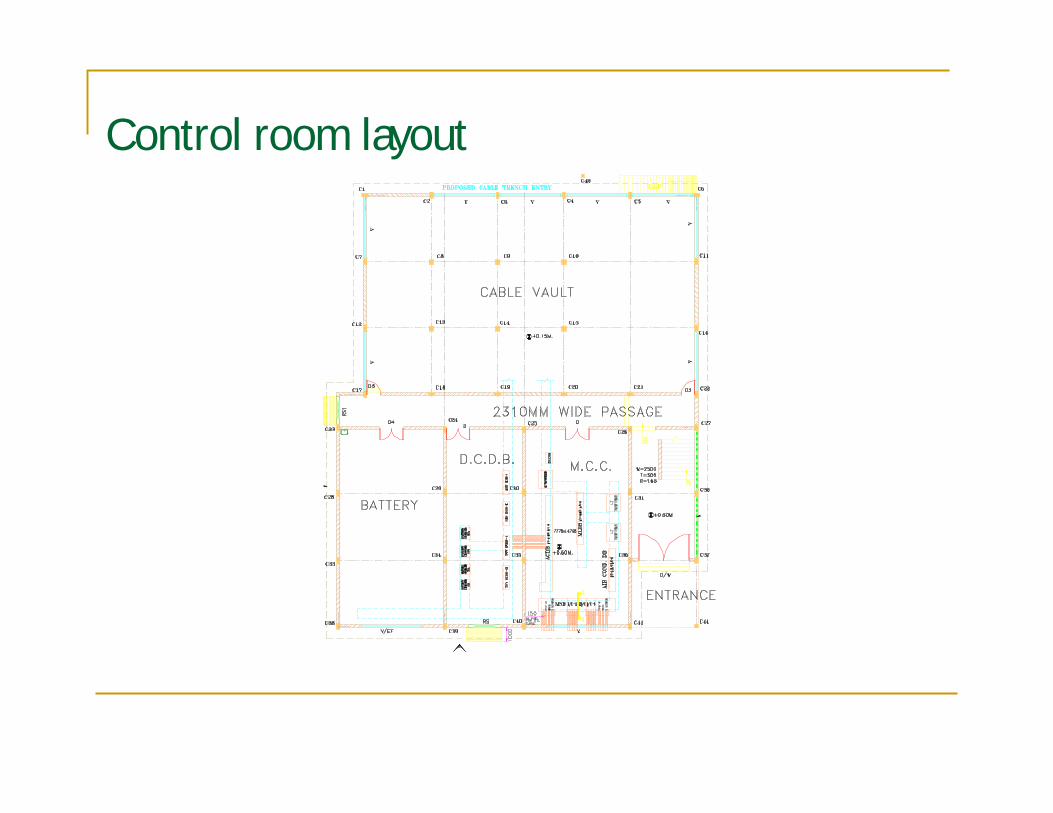
Control room layout
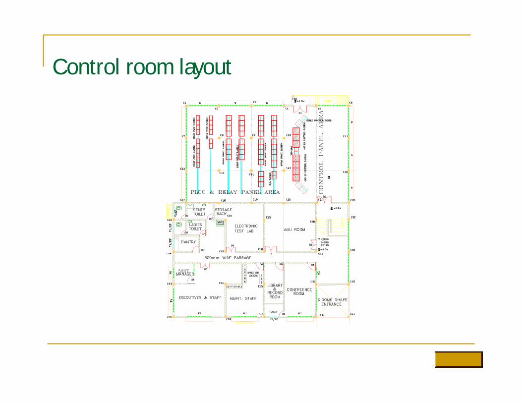
Control room layout
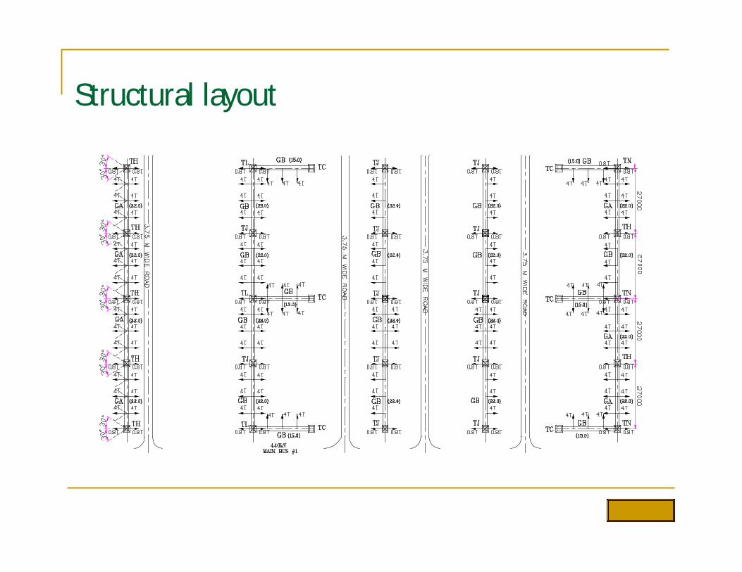
Structural layout
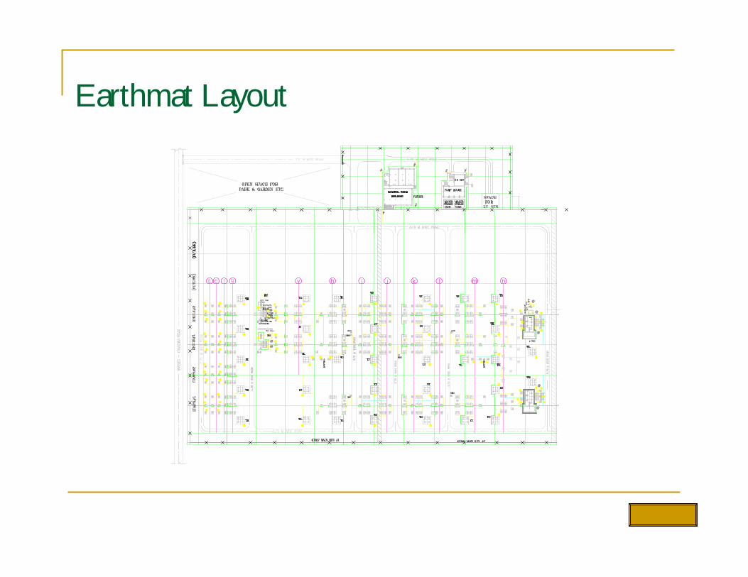
Earthmat Layout
@
@
@
@
@
@
@
@
@
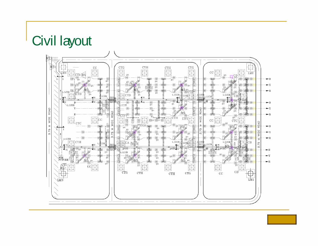
Civil layout
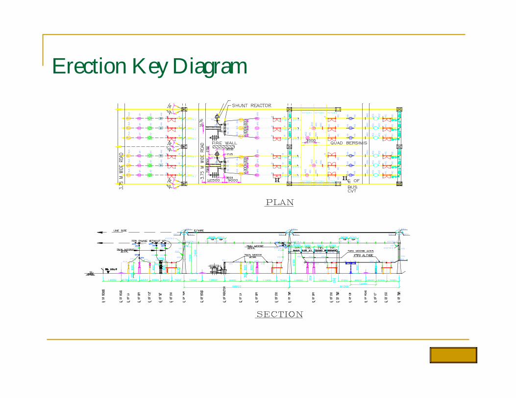
Erection Key Diagram
EW 2E W 2
4 S14 S1
4 D T T M -2
EW 1
4 I4 S1
4 LA 4 P 4 V4 S1 4 W4 W
4 S14 S1
4 I
4 S1
4 LA4 S 1
R 1
4 SST M -D
4 T 14 T 14 T 1
4 S1 4 S14 S1
EW 2EW 2
4 S14 S 1
4 S1
4 D T T M -1 4 S24 S2 4 S2
EW 1
4 SST M -D
4 T B SM4 T B SM 4 T B SM
4 P 14 I4 P 34 S1 4 S1
4 P 14 I4 I C1
4 S1 4 S14 S1
4 B4 I2 4 I14 I4 I C2
4 S1
4 C24 C1 4 I 14 B
EW 2EW 2
4 SST M -T
4 S2 4 S24 T M
4 S1 4 S14 S1
4 D T T M -14 D T T M -2
E W 1
4 S24 S2 4 S2
4 I 2
4 S1
4 IC2
4 D T T M -1
4 D T T M -1
4 D T T M -1
4 D T T M -1
4 D T T M -1
4 D T T M -1
4SST
M-D4L
A
4P4P
4P4LA
4LA
4W4V4V
4V 4W
4SST
M-D
4 D T T M -1
4 D T T M -1
4 D T T M -1
4SST
M-D
4I4I
4I4I
4I 4I
4W4P 4V4LA
4P4LA
4V
4P4LA
4V 4W
4SST
M-D
4 D T T M -1
4 D T T M -1
4SST
M-D
4I4I
4I4I
4 D T T M -1
4I
4SST
M-D
4I
4P3
R1R1
R1 4LA
4LA
4LA
4 D T T M -2
4P3
4P3
4I4I
4I
4 D T T M -2
4I4I
4 D T T M -2
4I
R1R1
R1
4LA
4LA
4LA
4P3
4P3
4I4I
4 D T T M -2
4 D T T M -2
4I4I
4P3
4I
4 D T T M -2
4I
4B
4B
4B
4 D T Q B-24 D T Q B-2 4 D T Q B-2
4I2
4I1
4I
4P1
4IC2
4P1
4IC1 4I
2
4I1
4I1
4B
4B
4B
4C2
4C1
4I1
4I2
4C2
4C1
4I1
4I2
4C2
4C1
4I1
4I2
4B
4B
4B
4P1
4I2
4I14IC2
4P1
4IC1
4I2
4I1
4I
4 D T Q B-14 D T Q B-1 4 D T Q B-1
4I1
4C2
4C1
4I1
4B
4I2
4B
4C2
4C1
4I1
4I2
4B
4C1
4C2
4I1
4I2
4W1
4W1
4W1
4W1
4W1
4W1
4W1
4W1
4W1
4W1
N1
R2
R2
N1
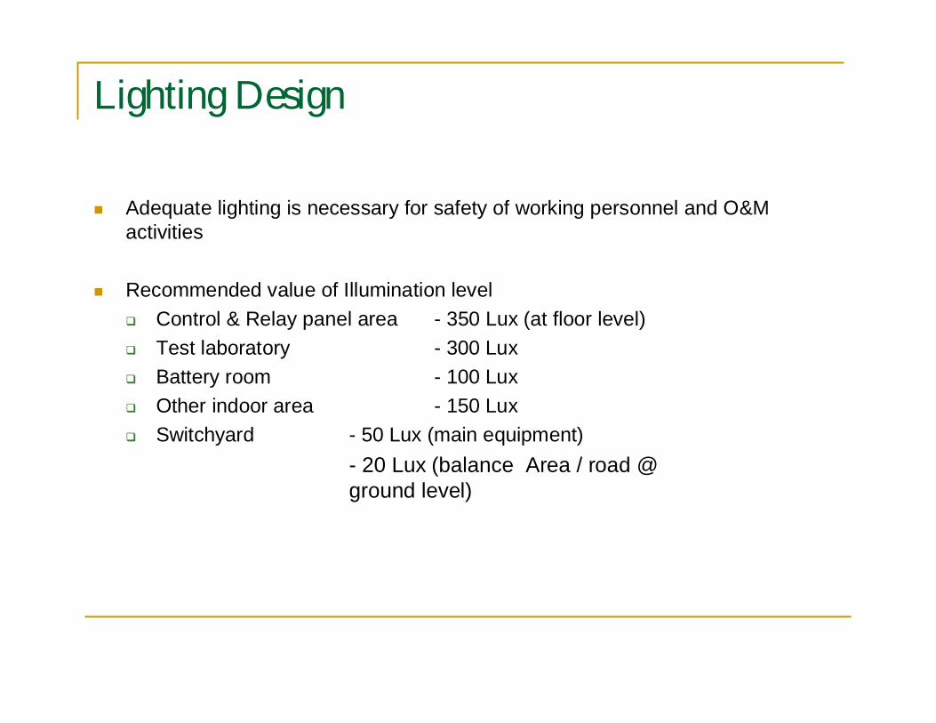
Lighting Design
Adequate lighting is necessary for safety of working personnel and O&Mactivities
Recommended value of Illumination levelControl & Relay panel area - 350 Lux (at floor level)Test laboratory - 300 LuxBattery room - 100 LuxOther indoor area - 150 LuxSwitchyard - 50 Lux (main equipment)
- 20 Lux (balance Area / road @ground level)
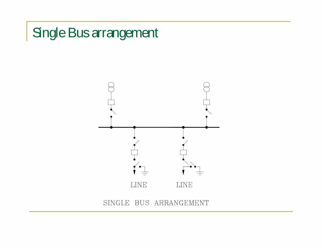
Single Bus arrangement
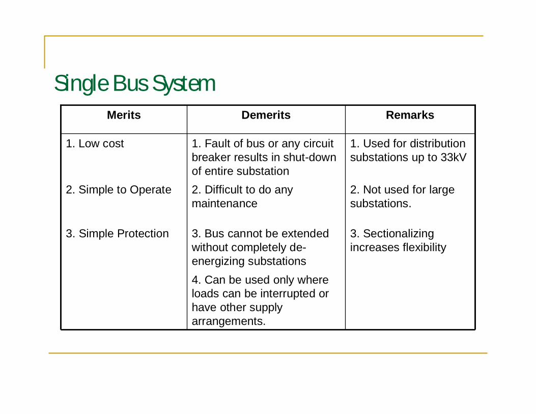
Single Bus System
4. Can be used only whereloads can be interrupted orhave other supplyarrangements.
3. Sectionalizingincreases flexibility
3. Bus cannot be extendedwithout completely de-energizing substations
3. Simple Protection
2. Not used for largesubstations.
2. Difficult to do anymaintenance
2. Simple to Operate
1. Used for distributionsubstations up to 33kV
1. Fault of bus or any circuitbreaker results in shut-downof entire substation
1. Low cost
RemarksDemeritsMerits
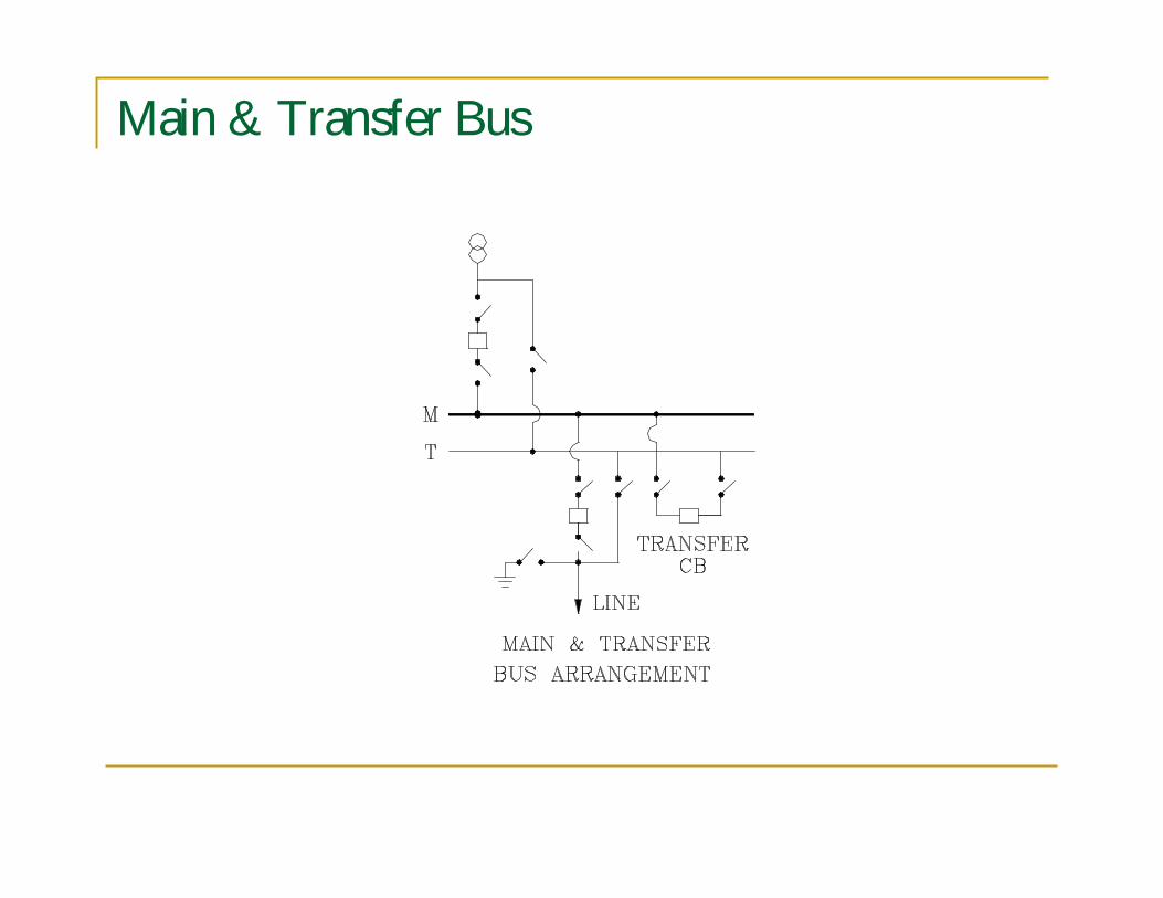
Main & Transfer Bus
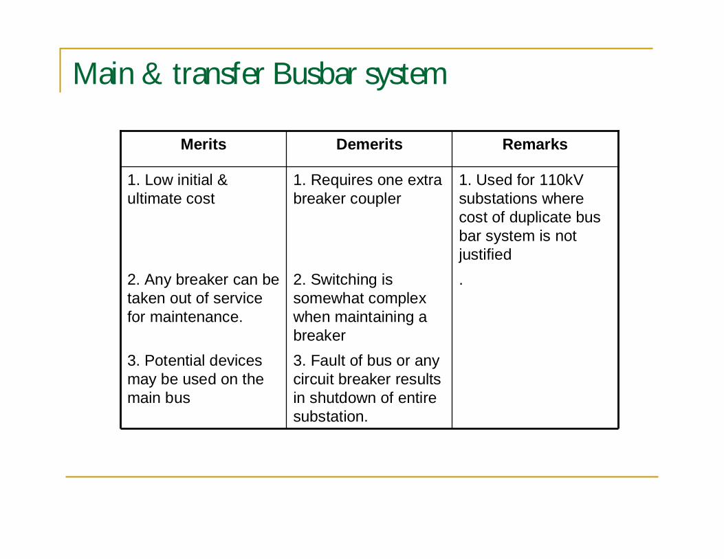
Main & transfer Busbar system
3. Fault of bus or anycircuit breaker resultsin shutdown of entiresubstation.
3. Potential devicesmay be used on themain bus
.2. Switching issomewhat complexwhen maintaining abreaker
2. Any breaker can betaken out of servicefor maintenance.
1. Used for 110kVsubstations wherecost of duplicate busbar system is notjustified
1. Requires one extrabreaker coupler
1. Low initial &ultimate cost
RemarksDemeritsMerits
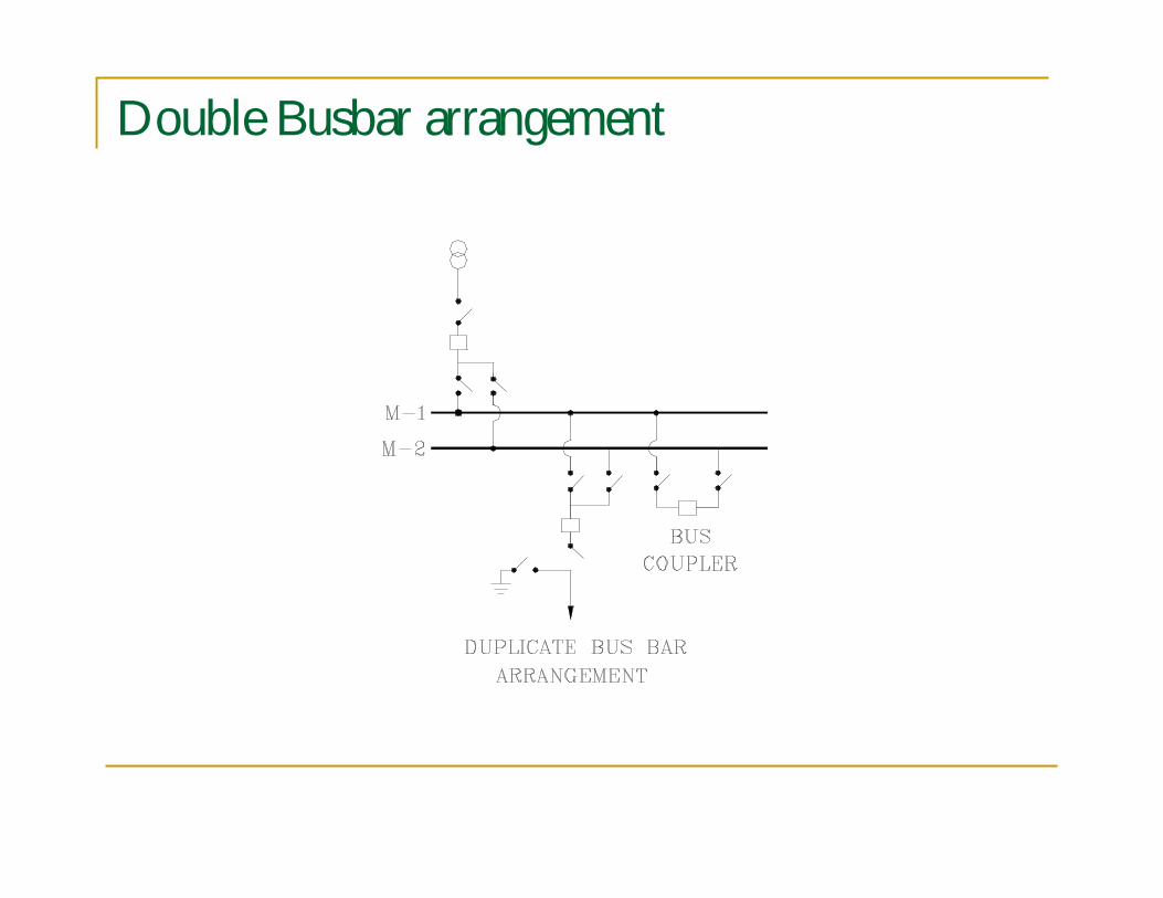
Double Busbar arrangement
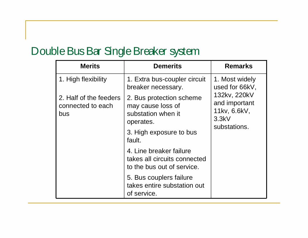
Double Bus Bar Single Breaker system
5. Bus couplers failuretakes entire substation outof service.
4. Line breaker failuretakes all circuits connectedto the bus out of service.
3. High exposure to busfault.
2. Bus protection schememay cause loss ofsubstation when itoperates.
2. Half of the feedersconnected to eachbus
1. Most widelyused for 66kV,132kv, 220kVand important11kv, 6.6kV,3.3kVsubstations.
1. Extra bus-coupler circuitbreaker necessary.
1. High flexibility
RemarksDemeritsMerits
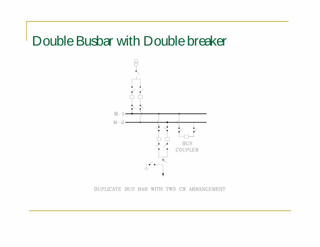
Double Busbar with Double breaker
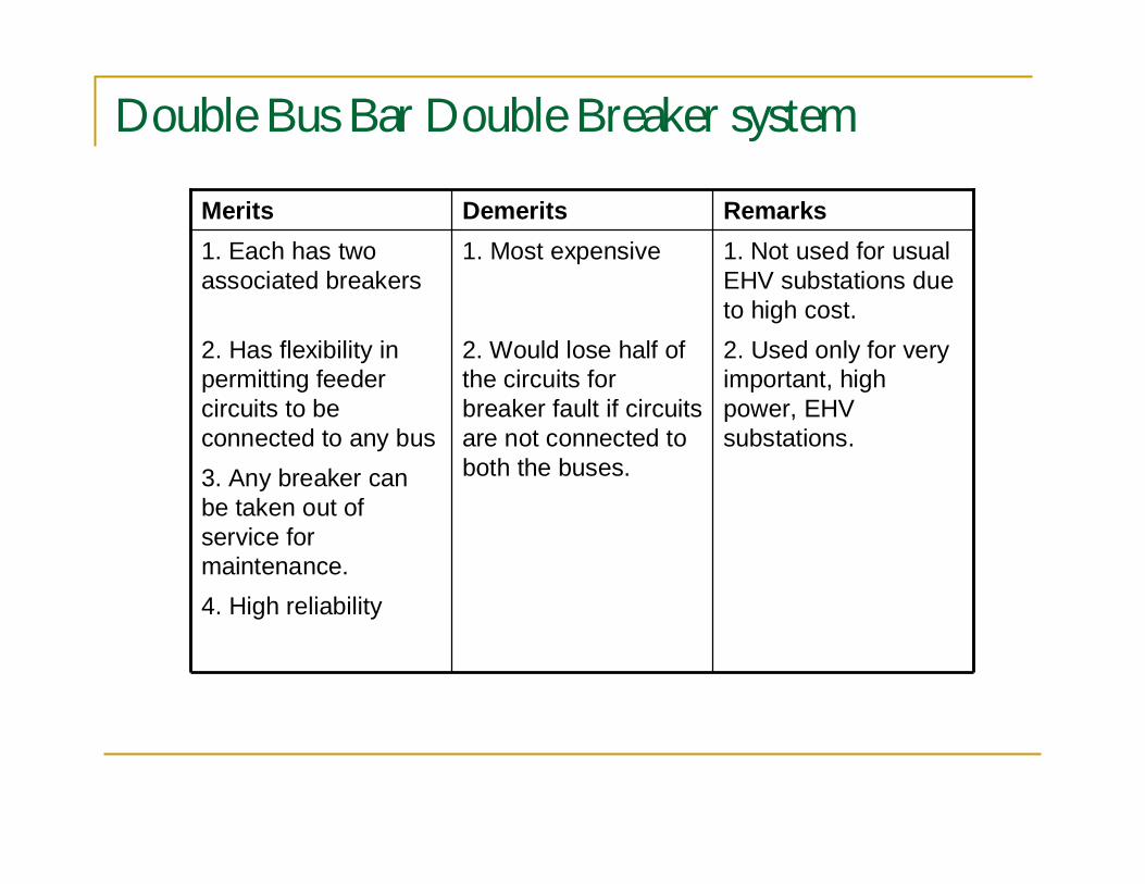
Double Bus Bar Double Breaker system
4. High reliability
3. Any breaker canbe taken out ofservice formaintenance.
2. Used only for veryimportant, highpower, EHVsubstations.
2. Would lose half ofthe circuits forbreaker fault if circuitsare not connected toboth the buses.
2. Has flexibility inpermitting feedercircuits to beconnected to any bus
1. Not used for usualEHV substations dueto high cost.
1. Most expensive1. Each has twoassociated breakers
RemarksDemeritsMerits
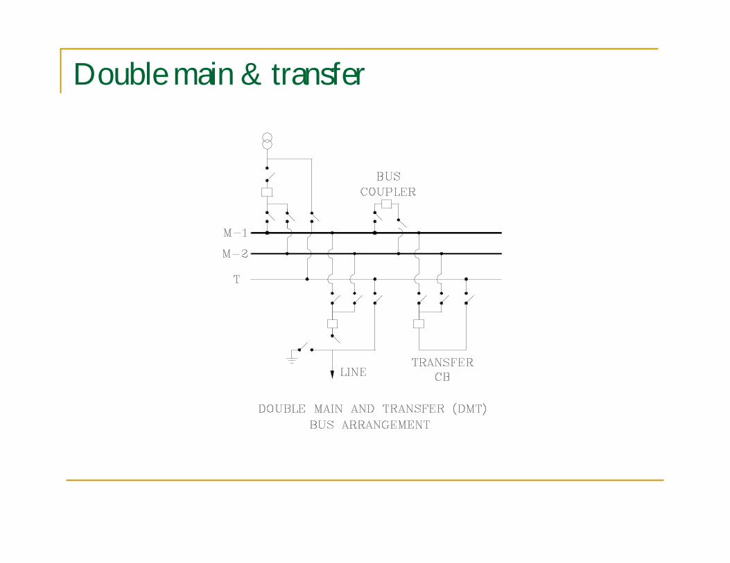
Double main & transfer
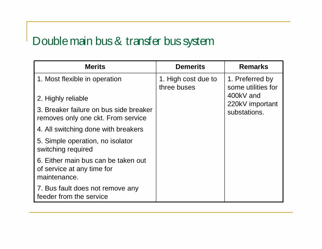
Double main bus & transfer bus system
7. Bus fault does not remove anyfeeder from the service
6. Either main bus can be taken outof service at any time formaintenance.
5. Simple operation, no isolatorswitching required
4. All switching done with breakers
3. Breaker failure on bus side breakerremoves only one ckt. From service
2. Highly reliable
1. Preferred bysome utilities for400kV and220kV importantsubstations.
1. High cost due tothree buses
1. Most flexible in operation
RemarksDemeritsMerits
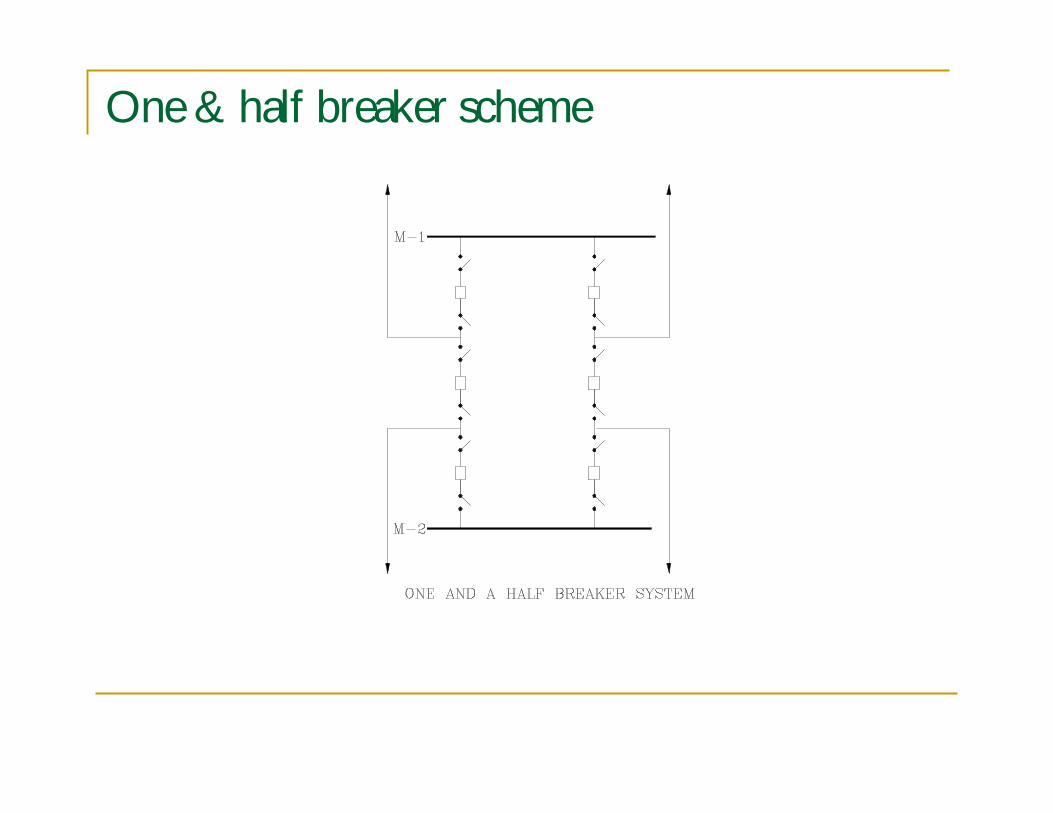
One & half breaker scheme
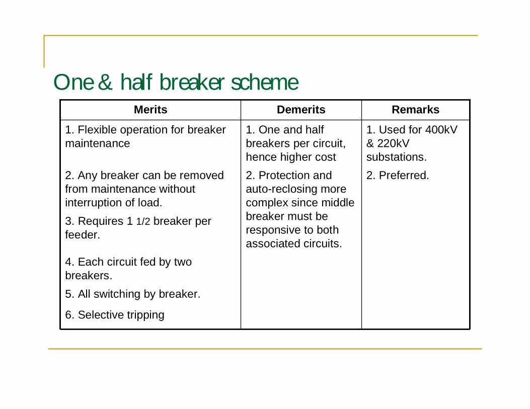
One & half breaker scheme
6. Selective tripping
5. All switching by breaker.
4. Each circuit fed by twobreakers.
3. Requires 1 1/2 breaker perfeeder.
2. Preferred.2. Protection andauto-reclosing morecomplex since middlebreaker must beresponsive to bothassociated circuits.
2. Any breaker can be removedfrom maintenance withoutinterruption of load.
1. Used for 400kV& 220kVsubstations.
1. One and halfbreakers per circuit,hence higher cost
1. Flexible operation for breakermaintenance
RemarksDemeritsMerits
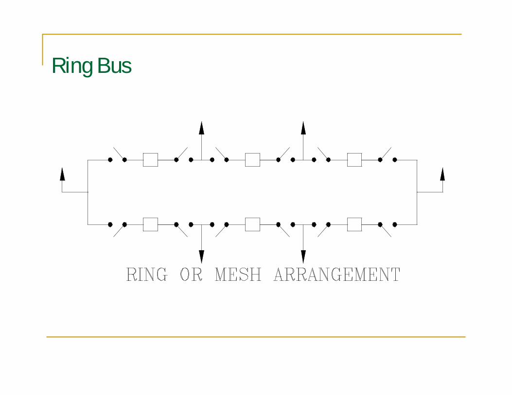
Ring Bus
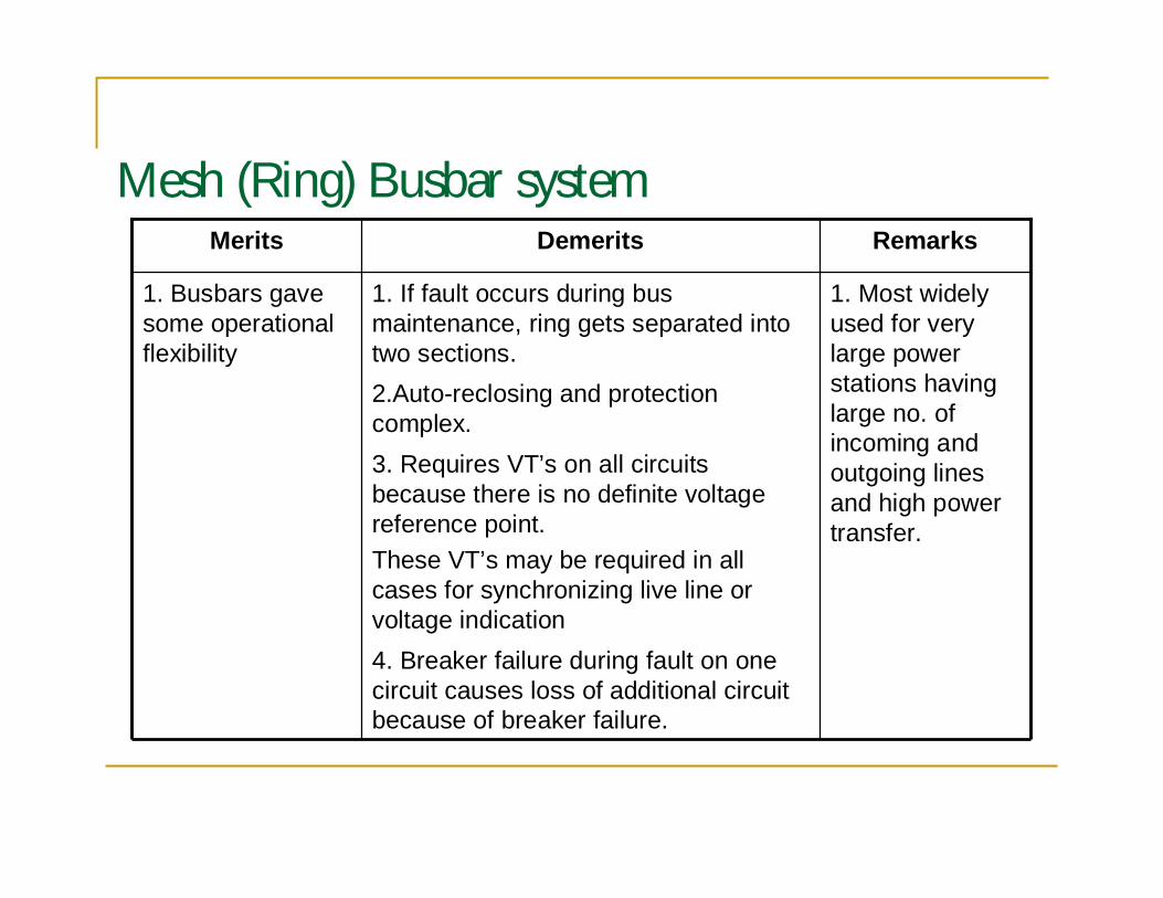
Mesh (Ring) Busbar system
4. Breaker failure during fault on onecircuit causes loss of additional circuitbecause of breaker failure.
3. Requires VT’s on all circuitsbecause there is no definite voltagereference point.These VT’s may be required in allcases for synchronizing live line orvoltage indication
2.Auto-reclosing and protectioncomplex.
1. Most widelyused for verylarge powerstations havinglarge no. ofincoming andoutgoing linesand high powertransfer.
1. If fault occurs during busmaintenance, ring gets separated intotwo sections.
1. Busbars gavesome operationalflexibility
RemarksDemeritsMerits
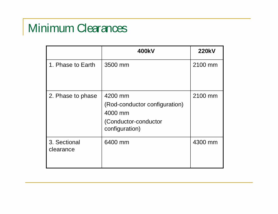
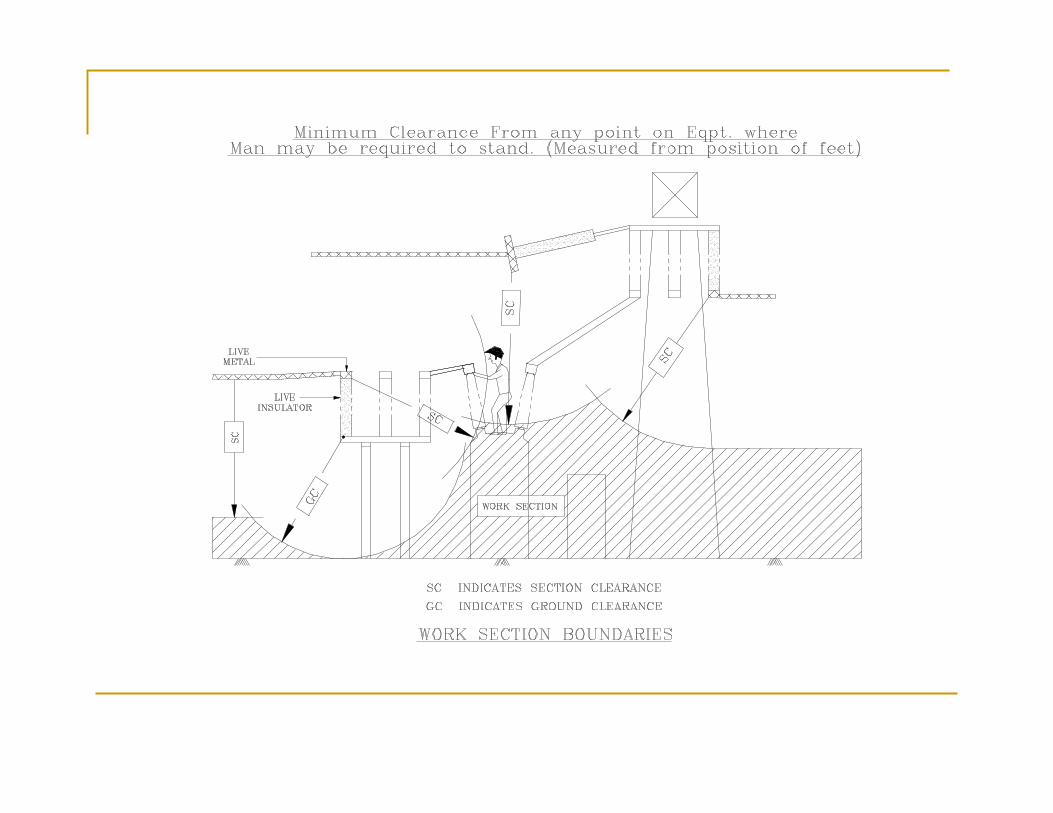
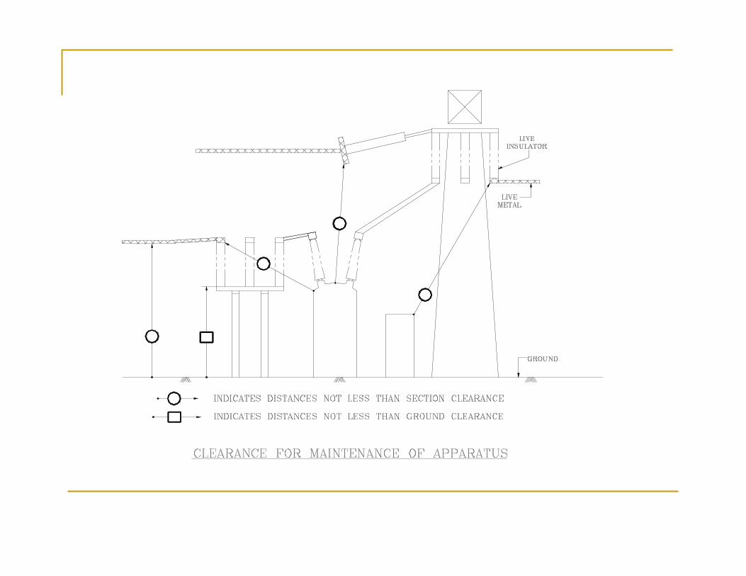
Minimum Clearances
4300 mm6400 mm3. Sectionalclearance
2100 mm4200 mm(Rod-conductor configuration)4000 mm(Conductor-conductorconfiguration)
2. Phase to phase
2100 mm3500 mm1. Phase to Earth
220kV400kV
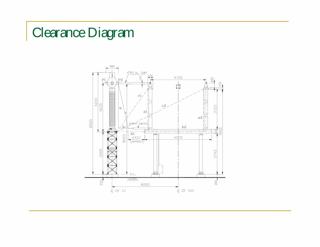
Clearance Diagram
Bus Bar Design
Continuous current rating. Ampacity calculation as per IEEE:738
Short time current rating (40kA for 1 Sec.) IEC-865
Stresses in Tubular Busbar
Natural frequency of Tubular Busbar
Deflection of Tube
Cantilever strength of Post Insulator
Aeolian Vibrations
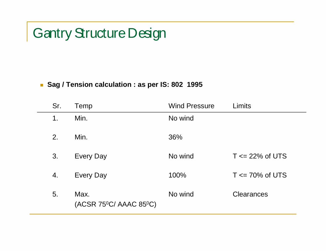
Gantry Structure Design
ClearancesNo windMax.(ACSR 750C/ AAAC 850C)
5.
T <= 70% of UTS100%Every Day4.
T <= 22% of UTSNo windEvery Day3.
36%Min.2.
No windMin.1.
LimitsWind PressureTempSr.
Sag / Tension calculation : as per IS: 802 1995
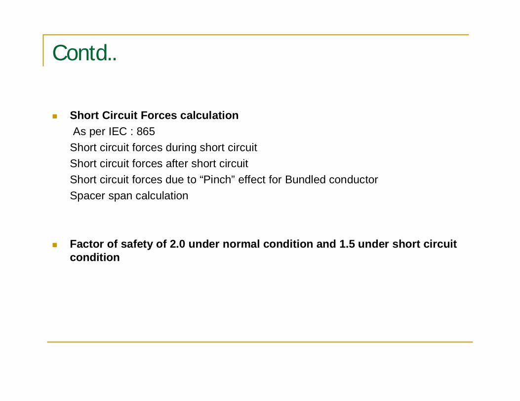
Contd..
Short Circuit Forces calculationAs per IEC : 865
Short circuit forces during short circuitShort circuit forces after short circuitShort circuit forces due to “Pinch” effect for Bundled conductorSpacer span calculation
Factor of safety of 2.0 under normal condition and 1.5 under short circuitcondition
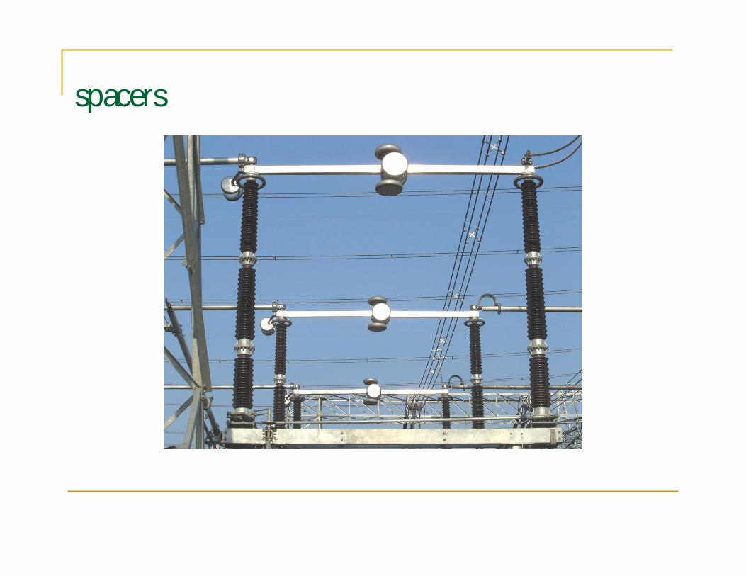
spacers
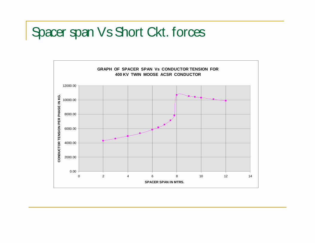
Spacer span Vs Short Ckt. forces
GRAPH OF SPACER SPAN Vs CONDUCTOR TENSION FOR400 KV TWIN MOOSE ACSR CONDUCTOR
0.00
2000.00
4000.00
6000.00
8000.00
10000.00
12000.00
0 2 4 6 8 10 12 14
SPACER SPAN IN MTRS.
COND
UCTO
R TE
NSIO
N PE
R P
HASE
IN K
G.
Earthing Design
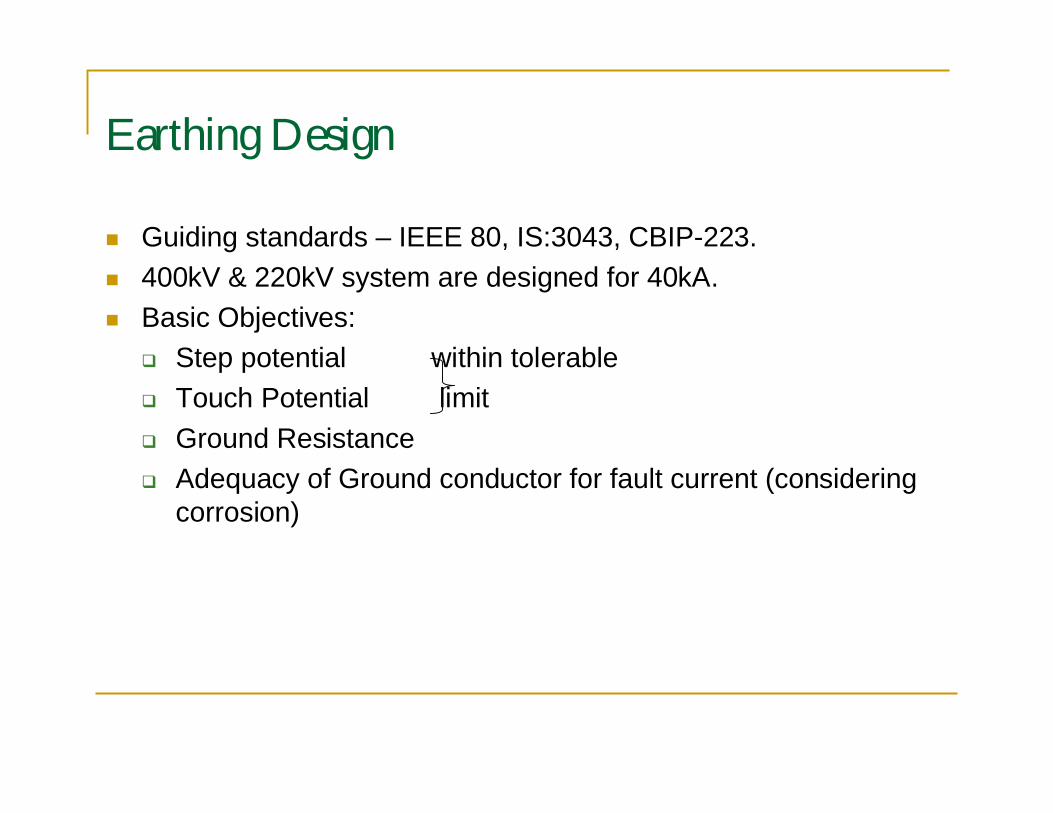
Guiding standards – IEEE 80, IS:3043, CBIP-223.400kV & 220kV system are designed for 40kA.Basic Objectives:
Step potential within tolerableTouch Potential limitGround ResistanceAdequacy of Ground conductor for fault current (consideringcorrosion)
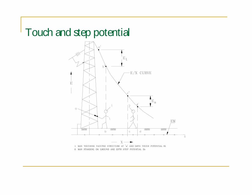
Touch and step potential
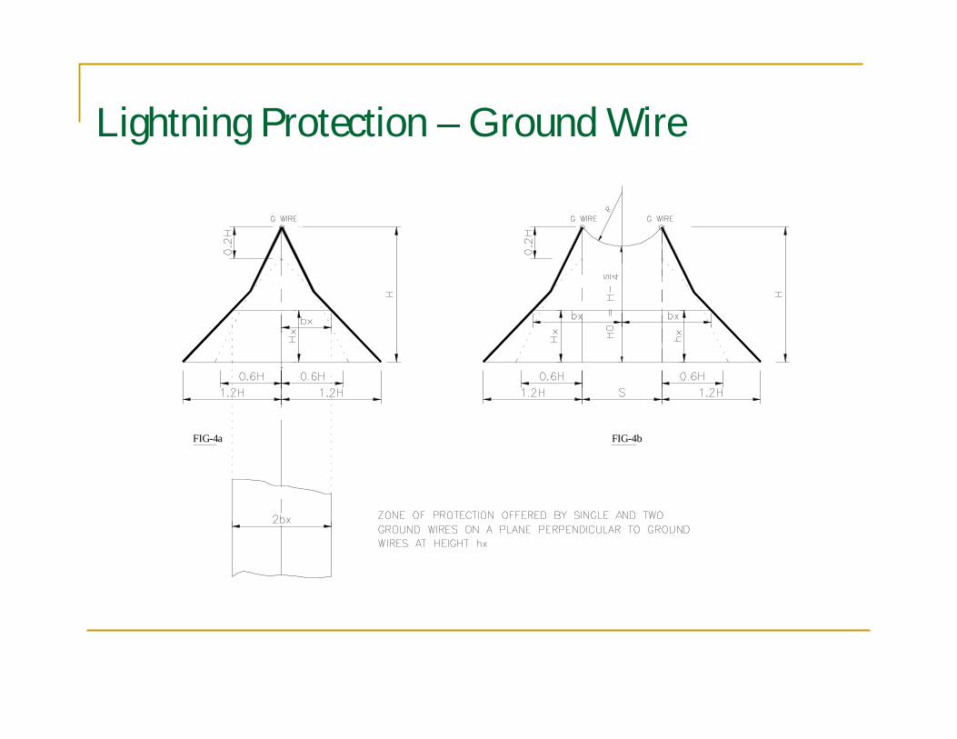
Lightning Protection – Ground Wire
FIG-4bFIG-4a
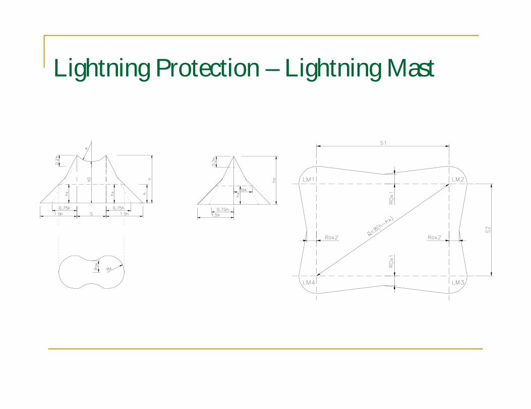
Lightning Protection – Lightning Mast