40 Sea Pro/Marathon - 30/40 HP - Marine Motorsmarine-uae.ru/wp-content/uploads/catalogs/outboard...
81
i Welcome Aboard! Proper care and maintenance is an important part in keeping your Mercury Product operating at peak efficiency for maximum performance and economy. The enclosed Owner's Registration Card is your key to trouble-free family fun. Refer to your Operation and Maintenance Manual for full details of your warranty coverage. Details of your nearest dealer can be found on www.marinepower.com where country maps and full contact information are displayed. Is your engine properly registered for warranty purpose? Please check on www.marinepower.com. If necessary, please contact your local dealer. If the outboard motor’s serial number plate contains the CE mark in the lower left-hand corner, the following statement applies: This outboard motor manufactured by Mercury Marine, Fond du Lac, WI, USA or Marine Power Europe Inc. Park Industrel, de Petit-Rechain, Belgium complies with the requirements of the following directives and standards, as amended: Recreational Craft Directive: 94/25/EC; std. ISO 8665, ISO 11547 Machinery Directive: 98/37/EC, EMC Directive: 89/336/EC; std. EN50081-1, SAE J551 (CISPR Pub. 12), EN 50082-1, IEC 61000 PT4-2, IEC 61000 PT4-3 Patrick C. Mackey President, Mercury Marine, Fond du Lac, WI USA European Regulations Contact: Product Environmental Engineering Department, Mercury Marine, Fond du Lac, WI USA © 2004 Mercury Marine 40 Sea Pro/Marathon - 30/40 HP 90-10148050 304
-
Upload
truonghanh -
Category
Documents
-
view
216 -
download
0
Transcript of 40 Sea Pro/Marathon - 30/40 HP - Marine Motorsmarine-uae.ru/wp-content/uploads/catalogs/outboard...
i
Welcome Aboard!Proper care and maintenance is an important part in keeping your Mercury Product operating at peakefficiency for maximum performance and economy. The enclosed Owner's Registration Card is your keyto trouble-free family fun. Refer to your Operation and Maintenance Manual for full details of your warrantycoverage.Details of your nearest dealer can be found on www.marinepower.com where country maps and fullcontact information are displayed.Is your engine properly registered for warranty purpose? Please check on www.marinepower.com. Ifnecessary, please contact your local dealer.If the outboard motor’s serial number plate contains the CE mark in the lower left-hand corner, thefollowing statement applies:This outboard motor manufactured by Mercury Marine, Fond du Lac, WI, USA or Marine Power EuropeInc. Park Industrel, de Petit-Rechain, Belgium complies with the requirements of the following directivesand standards, as amended:
Recreational Craft Directive: 94/25/EC; std. ISO 8665, ISO 11547
Machinery Directive: 98/37/EC,
EMC Directive: 89/336/EC; std. EN50081-1, SAE J551 (CISPR Pub. 12),EN 50082-1, IEC 61000 PT4-2, IEC 61000 PT4-3
Patrick C. Mackey
President, Mercury Marine, Fond du Lac, WI USA
European Regulations Contact:
Product Environmental Engineering Department, Mercury Marine, Fond du Lac, WI USA
© 2
004
Mer
cury
Mar
ine
40 S
ea P
ro/M
arat
hon
- 30/
40 H
P90
-101
4805
0 3
04
TABLE OF CONTENTS
ii
Warranty Information
Transfer Of Warranty..............................................................................................................................................1Warranty Registration United States And Canada................................................................................................. 1Warranty Registration Outside The United States And Canada............................................................................. 1Mercury Marine Two Years Limited Warranty (Europe)......................................................................................... 2Mercury Marine One Year Limited Warranty (Confederation of Independent States, Middle-East, Africa)............ 33 Year Limited Warranty Against Corrosion...........................................................................................................5Warranty Coverage And Exclusions.......................................................................................................................6
GENERAL INFORMATION
Boater's Responsibilities......................................................................................................................................... 8Before Operating Your Outboard............................................................................................................................ 8Boat Horsepower Capacity..................................................................................................................................... 8High-Speed And High-Performance Boat Operation.............................................................................................. 9Outboard Remote Control Models .........................................................................................................................9Remote Steering Notice.........................................................................................................................................9Lanyard Stop Switch.............................................................................................................................................10Protecting People In The Water........................................................................................................................... 11Passenger Safety Message - Pontoon Boats And Deck Boats............................................................................11Wave And Wake Jumping.................................................................................................................................... 12Impact With Underwater Hazards.........................................................................................................................13Safety Instructions For Hand Tilled Outboards.....................................................................................................14Exhaust Emissions...............................................................................................................................................14Selecting Accessories For Your Outboard...........................................................................................................15Safe Boating Suggestions....................................................................................................................................16Recording Serial Number..................................................................................................................................... 1640 Sea Pro/Marathon - 30/40 HP Specifications..................................................................................................17Component Identification......................................................................................................................................1840 SeaPro/Marathon Component Identification....................................................................................................19
INSTALLATION
Installing Outboard...............................................................................................................................................20Propeller Selection...............................................................................................................................................21
TRANSPORTING
Trailering Boat/Outboard .....................................................................................................................................22Transporting Portable Fuel Tanks........................................................................................................................ 22
FUEL & OIL
Gasoline Recommendations................................................................................................................................24Oil Recommendation............................................................................................................................................24Fuel and Oil Ratio.................................................................................................................................................24Mixing Fuel and Oil...............................................................................................................................................25Filling Oil Injection System...................................................................................................................................25
TABLE OF CONTENTS
iii
Filling Fuel Tank...................................................................................................................................................26
FEATURES & CONTROLS
Remote Control Features..................................................................................................................................... 27Warning System - Electric Start Models............................................................................................................... 27Warning Horn System - Manual Start Models...................................................................................................... 28Engine Over-Speed Limiter.................................................................................................................................. 29Manual Tilt System............................................................................................................................................... 30Power Trim And Tilt (if equipped)......................................................................................................................... 36Throttle Grip Friction Adjustment - Tiller Handle Models...................................................................................... 39Steering Friction Adjustment ............................................................................................................................... 39Trim Tab Adjustment............................................................................................................................................ 40
OPERATION
Pre-Starting Check List......................................................................................................................................... 42Operating In Freezing Temperatures................................................................................................................... 42Operating In Salt Water Or Polluted Water.......................................................................................................... 42Operating at High Elevations................................................................................................................................ 42Engine Break-in Procedure.................................................................................................................................. 42Starting The Engine - Electric Start Remote Control Models............................................................................... 43Starting The Engine - Tiller Handle Models And Manual Start Remote Control Models...................................... 45Gear Shifting.........................................................................................................................................................49Stopping The Engine ........................................................................................................................................... 49Emergency Starting - Electric Start Models .........................................................................................................50Emergency Starting - Manual Start Models..........................................................................................................52
MAINTENANCE
Outboard Care......................................................................................................................................................54EPA Emissions..................................................................................................................................................... 54Inspection And Maintenance Schedule................................................................................................................ 55Flushing The Cooling System...............................................................................................................................55Top Cowl Removal And Installation......................................................................................................................56Battery Inspection ................................................................................................................................................57Fuel System..........................................................................................................................................................57Exterior Care........................................................................................................................................................ 61Steering Link Rod Fasteners................................................................................................................................ 61Fuse Replacement - Electric Start Models........................................................................................................... 62Corrosion Control Anode...................................................................................................................................... 63Propeller Replacement......................................................................................................................................... 63Spark Plug Inspection And Replacement............................................................................................................. 65Lubrication Points................................................................................................................................................. 66Checking Power Trim Fluid.................................................................................................................................. 68Gearcase Lubrication........................................................................................................................................... 69Submerged Outboard........................................................................................................................................... 70
STORAGE
Storage Preparation............................................................................................................................................. 71Protecting External Outboard Components..........................................................................................................71
TABLE OF CONTENTS
iv
Protecting Internal Engine Components............................................................................................................... 71Gearcase..............................................................................................................................................................71Positioning Outboard For Storage........................................................................................................................71Battery Storage.....................................................................................................................................................72
TROUBLESHOOTING
Starter Motor Will Not Crank The Engine (Electric Start Models)......................................................................... 73Engine Will Not Start............................................................................................................................................ 73Engine Runs Erratically........................................................................................................................................ 73Performance Loss................................................................................................................................................ 73Battery Will Not Hold Charge................................................................................................................................74
OWNER SERVICE ASSISTANCE
Local Repair Service............................................................................................................................................ 75Service Away From Home....................................................................................................................................75Parts And Accessories Inquiries...........................................................................................................................75Service Assistance............................................................................................................................................... 75Mercury Marine Service Offices........................................................................................................................... 75
WARRANTY INFORMATION
1
Transfer Of WarrantyThe limited warranty is transferable to a subsequent purchaser, but only for the remainder of the unused portionof the limited warranty. This will not apply to products used for commercial applications.To transfer the warranty to the subsequent owner, send or fax a copy of the bill of sale or purchase agreement,new owner’s name, address and engine serial number to Mercury Marine’s warranty registration department.Mercury MarineAttn: Warranty Registration DepartmentW6250 W. Pioneer RoadP.O. Box 1939Fond du Lac, WI 54936-1939920-929-5054Upon processing the transfer of warranty, Mercury Marine will send registration verification to the new owner ofthe product by mail.There is no charge for this service.For products purchased outside the United States and Canada, contact the distributor in your country, or theMercury Marine Service Office closest to you.
Warranty Registration United States And Canada1. You may change your address at any time, including at time of warranty claim, by calling Mercury Marine or
sending a letter or fax with your name, old address, new address, and engine serial number to MercuryMarine’s warranty registration department. Your dealer can also process this change of information.Mercury MarineAttn: Warranty Registration DepartmentW6250 W. Pioneer RoadP.O. Box 1939Fond du Lac, WI 54936-1939920-929-5054
NOTE: Registration lists must be maintained by Mercury Marine and any dealer on marine products sold in theUnited States, should a safety recall notification under the Federal Safety Act be required.2. To be eligible for warranty coverage, the product must be registered with Mercury Marine. At the time of sale,
the dealer should complete the warranty registration and immediately submit it to Mercury Marine viaMercNET, E-mail, or mail. Upon receipt of this warranty registration, Mercury Marine will record theregistration.
3. Upon processing the warranty registration, Mercury Marine will send registration verification by mail to thepurchaser of the product. If this registration verification is not received within 30 days, please contact yourselling dealer immediately. Warranty coverage is not effective until your product is registered with MercuryMarine.
Warranty Registration Outside The United States And Canada1. It is important that your selling dealer fills out the Warranty Registration Card completely and mails it to the
distributor or Marine Power Service Center responsible for administering the warranty registration/claimprogram for your area.
2. The Warranty Registration Card identifies your name and address, product model and serial numbers, dateof sale, type of use and the selling distributor's/dealer's code number, name and address. The distributor/dealer also certifies that you are the original purchaser and user of the product.
3. A copy of the Warranty Registration Card, designated as the Purchaser's Copy, MUST be given to youimmediately after the card has been completely filled out by the selling distributor/dealer. This card representsyour factory registration identification, and should be retained by you for future use when required. Shouldyou ever require warranty service on this product, your dealer may ask you for the Warranty RegistrationCard to verify date of purchase and to use the information on the card to prepare the warranty claim forms.
WARRANTY INFORMATION
2
4. In some countries, the Marine Power Service Center will issue you a permanent (plastic) WarrantyRegistration Card within 30 days after receiving the Factory Copy of the Warranty Registration Card fromyour distributor/dealer. If you receive a plastic Warranty Registration Card, you may discard the Purchaser'sCopy that you received from the distributor/dealer when you purchased the product. Ask your distributor/dealer if this plastic card program applies to you.
IMPORTANT: Registration lists must be maintained by the factory and dealer in some countries by law. It is ourdesire to have ALL products registered at the factory should it ever be necessary to contact you. Make sure yourdealer/distributor fills out the warranty registration card immediately and sends the factory copy to the Marine PowerInternational Service Center for your area.5. For further information concerning the Warranty Registration Card and its relationship to Warranty Claim
processing, refer to the International Warranty.
Mercury Marine Two Years Limited Warranty (Europe)WHAT IS COVERED: Mercury Marine warrants each new Mercury Outboard, Mariner Outboard, Jet Products,Thruster Electric Trolling Motors, Mercruiser Inboard or Sterndrive engine products to be free of defects in materialand workmanship during the period described below.DURATION OF COVERAGE: This Limited Warranty provides coverage for two (2) years from the date the productis first sold to a recreational use retail purchaser, or the date on which the product is first put into service, whicheveroccurs first. Commercial users of these products receive warranty coverage of two (2) years from the date of firstretail sale, or the accumulation of 500 hours of operation, whichever occurs first. Commercial use is defined asany work or employment related use of the product, or any use of the product which generates income, for anypart of the warranty period, even if the product is only occasionally used for such purposes. The repair orreplacement of parts, or the performance of service under this warranty, does not extend the life of this warrantybeyond its original expiration date. Unexpired warranty coverage can be transferred to one recreational use to asubsequent recreational use customer upon proper re–registration of the product.CONDITIONS THAT MUST BE MET IN ORDER TO OBTAIN WARRANTY COVERAGE: Warranty coverage isavailble only to retail customers that purchase from a Dealer authorized by Mercury Marine to distribute the productin the country in which the sale occurred, and then only after the Mercury Marine specified pre–delivery inspectionprocess is completed and documented. Warranty coverage becomes available upon proper registration of theproduct by the authorized dealer. Inaccurate warranty registration information regarding recreational use, orsubsequent change of use from recreational to commercial (unless properly re–registered) may void the warrantyat the sole discretion of Mercury Marine. Routine maintenance outlined in the Operation and Maintenance Manualmust be timely performed in order to maintain warranty coverage. If this maintenance is performed by the retailcustomer Mercury Marine reserves the right to make future warranty coverage contingent on proof of propermaintenance.WHAT MERCURY WILL DO: Mercury’s sole and exclusive obligation under this warranty is limited to, at our option,repairing a defective part, replacing such part or parts with new or Mercury Marine certified re–manufactured parts,or refunding the purchase price of the Mercury product. Mercury reserves the right to improve or modify productsfrom time to time without assuming an obligation to modify products previously manufactured.HOW TO OBTAIN WARRANTY COVERAGE: The customer must provide Mercury with a reasonable opportunityto repair, and reasonable access to the product for warranty service. Warranty claims shall be made by deliveringthe product for inspection to a Mercury dealer authorized to service the product. If purchaser cannot deliver theproduct to such a dealer, written notice must be given to Mercury. We will then arrange for the inspection and anycovered repair. Purchaser in that case shall pay for all related transportation charges and/or travel time. If theservice provided is not covered by this warranty, purchaser shall pay for all related labor and material, and anyother expenses associated with that service. Purchaser shall not, unless requested by Mercury, ship the productor parts of the product directly to Mercury. The warranty registration card is the only valid registration identificationand must be presented to the dealer at the time warranty service is requested in order to obtain coverage.
WARRANTY INFORMATION
3
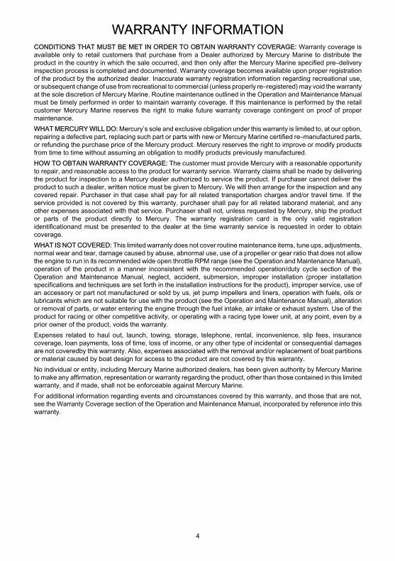
WHAT IS NOT COVERED: This limited warranty does not cover routine maintenance items, tune ups, adjustments,normal wear and tear, damage caused by abuse, abnormal use, use of a propeller or gear ratio that does not allowthe engine to run in its recommended wide open throttle RPM range (see the Operation and Maintenance Manual),operation of the product in a manner inconsistent with the recommended operation/duty cycle section of theOperation and Maintenance Manual, neglect, accident, submersion, improper installation (proper installationspecifications and techniques are set forth in the installation instructions for the product), improper service, use ofan accessory or part not manufactured or sold by us, jet pump impellers and liners, operation with fuels, oils orlubricants which are not suitable for use with the product (see the Operation and Maintenance Manual), alterationor removal of parts, or water entering the engine through the fuel intake, air intake or exhaust system. Use of theproduct for racing or other competitive activity, or operating with a racing type lower unit, at any point, even by aprior owner of the product, voids the warranty.Expenses related to haul out, launch, towing, storage, telephone, rental, inconvenience, slip fees, insurancecoverage, loan payments, loss of time, loss of income, or any other type of incidental or consequential damagesare not covered by this warranty. Also, expenses associated with the removal and/or replacement of boat partitionsor material caused by boat design for access to the product are not covered by this warranty.No individual or entity, including Mercury Marine authorized dealers, has been given authority by Mercury Marineto make any affirmation, representation or warranty regarding the product, other than those contained in this limitedwarranty, and if made, shall not be enforceable against Mercury Marine.For additional information regarding events and circumstances covered by this warranty, and those that are not,see the Warranty Coverage section of the Operation and Maintenance Manual, incorporated by reference into thiswarranty.
DISCLAIMERS AND LIMITATIONS:
THE IMPLIED WARRANTIES OF MERCHANTABILITY AND FITNESS FOR A PARTICULARPURPOSE ARE EXPRESSLY DISCLAIMED. TO THE EXTENT THAT THEY CANNOT BEDISCLAIMED, THE IMPLIED WARRANTIES ARE LIMITED IN DURATION TO THE LIFE OF THEEXPRESS WARRANTY. INCIDENTAL AND CONSEQUENTIAL DAMAGES ARE EXCLUDEDFROM COVERAGE UNDER THIS WARRANTY. SOME STATES/COUNTRIES DO NOT ALLOWFOR THE DISCLAIMERS, LIMITATIONS AND EXCLUSIONS IDENTIFIED ABOVE, AS ARESULT, THEY MAY NOT APPLY TO YOU. THIS WARRANTY GIVES YOU SPECIFIC LEGALRIGHTS, AND YOU MAY ALSO HAVE OTHER LEGAL RIGHTS WHICH VARY FROM STATETO STATE AND COUNTRY TO COUNTRY.
Mercury Marine One Year Limited Warranty (Confederation ofIndependent States, Middle-East, Africa)WHAT IS COVERED: Mercury Marine warrants each new Mercury outboard, Mariner outboard, Jet Products,Thruster Electric Trolling Motors, Mercruiser Inboard or Sterndrive engine products to be free of defects in materialand workmanship during the period described below.DURATION OF COVERAGE: This Limited Warranty provides coverage for one (1) year from the date the productis first sold to a recreational use retail purchaser, or the date on which the product is first put into service, whicheveroccurs first. Commercial users of these products receive warranty coverage of one (1) years from the date of firstretail sale, or the accumulation of 500 hours of operation, whichever occurs first. Commercial use is defined asany work or employment related use of the product, or any use of the product which generates income, for anypart of the warranty period, even if the product is only occasionally used for such purposes. The repair orreplacement of parts, or the performance of service under this warranty, does not extend the life of this warrantybeyond its original expiration date. Unexpired warranty coverage can be transferred to a subsequent purchaserupon proper re–registration of the product.
WARRANTY INFORMATION
4
CONDITIONS THAT MUST BE MET IN ORDER TO OBTAIN WARRANTY COVERAGE: Warranty coverage isavailable only to retail customers that purchase from a Dealer authorized by Mercury Marine to distribute theproduct in the country in which the sale occurred, and then only after the Mercury Marine specified pre–deliveryinspection process is completed and documented. Warranty coverage becomes available upon proper registrationof the product by the authorized dealer. Inaccurate warranty registration information regarding recreational use,or subsequent change of use from recreational to commercial (unless properly re–registered) may void the warrantyat the sole discretion of Mercury Marine. Routine maintenance outlined in the Operation and Maintenance Manualmust be timely performed in order to maintain warranty coverage. If this maintenance is performed by the retailcustomer Mercury Marine reserves the right to make future warranty coverage contingent on proof of propermaintenance.WHAT MERCURY WILL DO: Mercury’s sole and exclusive obligation under this warranty is limited to, at our option,repairing a defective part, replacing such part or parts with new or Mercury Marine certified re–manufactured parts,or refunding the purchase price of the Mercury product. Mercury reserves the right to improve or modify productsfrom time to time without assuming an obligation to modify products previously manufactured.HOW TO OBTAIN WARRANTY COVERAGE: The customer must provide Mercury with a reasonable opportunityto repair, and reasonable access to the product for warranty service. Warranty claims shall be made by deliveringthe product for inspection to a Mercury dealer authorized to service the product. If purchaser cannot deliver theproduct to such a dealer, written notice must be given to Mercury. We will then arrange for the inspection and anycovered repair. Purchaser in that case shall pay for all related transportation charges and/or travel time. If theservice provided is not covered by this warranty, purchaser shall pay for all related laborand material, and anyother expenses associated with that service. Purchaser shall not, unless requested by Mercury, ship the productor parts of the product directly to Mercury. The warranty registration card is the only valid registrationidentificationand must be presented to the dealer at the time warranty service is requested in order to obtaincoverage.WHAT IS NOT COVERED: This limited warranty does not cover routine maintenance items, tune ups, adjustments,normal wear and tear, damage caused by abuse, abnormal use, use of a propeller or gear ratio that does not allowthe engine to run in its recommended wide open throttle RPM range (see the Operation and Maintenance Manual),operation of the product in a manner inconsistent with the recommended operation/duty cycle section of theOperation and Maintenance Manual, neglect, accident, submersion, improper installation (proper installationspecifications and techniques are set forth in the installation instructions for the product), improper service, use ofan accessory or part not manufactured or sold by us, jet pump impellers and liners, operation with fuels, oils orlubricants which are not suitable for use with the product (see the Operation and Maintenance Manual), alterationor removal of parts, or water entering the engine through the fuel intake, air intake or exhaust system. Use of theproduct for racing or other competitive activity, or operating with a racing type lower unit, at any point, even by aprior owner of the product, voids the warranty.Expenses related to haul out, launch, towing, storage, telephone, rental, inconvenience, slip fees, insurancecoverage, loan payments, loss of time, loss of income, or any other type of incidental or consequential damagesare not coveredby this warranty. Also, expenses associated with the removal and/or replacement of boat partitionsor material caused by boat design for access to the product are not covered by this warranty.No individual or entity, including Mercury Marine authorized dealers, has been given authority by Mercury Marineto make any affirmation, representation or warranty regarding the product, other than those contained in this limitedwarranty, and if made, shall not be enforceable against Mercury Marine.For additional information regarding events and circumstances covered by this warranty, and those that are not,see the Warranty Coverage section of the Operation and Maintenance Manual, incorporated by reference into thiswarranty.

WARRANTY INFORMATION
5
DISCLAIMERS AND LIMITATIONS:
THE IMPLIED WARRANTIES OF MERCHANTABILITY AND FITNESS FOR A PARTICULARPURPOSE ARE EXPRESSLY DISCLAIMED. TO THE EXTENT THAT THEY CANNOT BEDISCLAIMED, THE IMPLIED WARRANTIES ARE LIMITED IN DURATION TO THE LIFE OF THEEXPRESS WARRANTY. INCIDENTAL AND CONSEQUENTIAL DAMAGES ARE EXCLUDEDFROM COVERAGE UNDER THIS WARRANTY. SOME STATES/COUNTRIES DO NOT ALLOWFOR THE DISCLAIMERS, LIMITATIONS AND EXCLUSIONS IDENTIFIED ABOVE, AS ARESULT, THEY MAY NOT APPLY TO YOU. THIS WARRANTY GIVES YOU SPECIFIC LEGALRIGHTS, AND YOU MAY ALSO HAVE OTHER LEGAL RIGHTS WHICH VARY FROM STATETO STATE AND COUNTRY TO COUNTRY.
3 Year Limited Warranty Against CorrosionWHAT IS COVERED: Mercury Marine warrants that each new Mercury, Mariner, Mercury Racing, Sport Jet, M2Jet Drive, Tracker by Mercury Marine Outboard, MerCruiser Inboard or sterndrive engine (Product) will not berendered inoperative as a direct result of corrosion for the period of time described below.DURATION OF COVERAGE: This limited corrosion warranty provides coverage for three (3) years from either thedate the product is first sold, or the date on which the product is first put into service, whichever occurs first. Therepair or replacement of parts, or the performance of service under this warranty does not extend the life of thiswarranty beyond its original expiration date. Unexpired warranty coverage can be transferred to subsequent(non-commercial use) purchaser upon proper re-registration of the product.CONDITIONS THAT MUST BE MET IN ORDER TO OBTAIN WARRANTY COVERAGE: Warranty coverage isavailable only to retail customers that purchase from a Dealer authorized by Mercury Marine to distribute theproduct in the country in which the sale occurred, and then only after the Mercury Marine specified pre-deliveryinspection process is completed and documented. Warranty coverage becomes available upon proper registrationof the product by the authorized dealer. Corrosion prevention devices specified in the Operation and MaintenanceManual must be in use on the boat, and routine maintenance outlined in the Operation and Maintenance Manualmust be timely performed (including without limitation the replacement of sacrificial anodes, use of specifiedlubricants, and touch-up of nicks and scratches) in order to maintain warranty coverage. Mercury Marine reservesthe right to make warranty coverage contingent upon proof of proper maintenance.WHAT MERCURY WILL DO: Mercury's sole and exclusive obligation under this warranty is limited to, at our option,repairing a corroded part, replacing such part or parts with new or Mercury Marine certified re-manufactured parts,or refunding the purchase price of the Mercury product. Mercury reserves the right to improve or modify productsfrom time to time without assuming an obligation to modify products previously manufactured.HOW TO OBTAIN WARRANTY COVERAGE: The customer must provide Mercury with a reasonable opportunityto repair, and reasonable access to the product for warranty service. Warranty claims shall be made by deliveringthe product for inspection to a Mercury dealer authorized to service the product. If purchaser cannot deliver theproduct to such a dealer, written notice must be given to Mercury. We will then arrange for the inspection and anycovered repair. Purchaser in that case shall pay for all related transportation charges and/or travel time. If theservice provided is not covered by this warranty, purchaser shall pay for all related labor and material, and anyother expenses associated with that service. Purchaser shall not, unless requested by Mercury, ship the productor parts of the product directly to Mercury. Proof of registered ownership must be presented to the dealer at thetime warranty service is requested in order to obtain coverage.WHAT IS NOT COVERED: This limited warranty does not cover electrical system corrosion; corrosion resultingfrom damage, corrosion which causes purely cosmetic damage, abuse or improper service; corrosion toaccessories, instruments, steering systems; corrosion to factory installed jet drive unit; damage due to marinegrowth; product sold with less than a one year limited Product warranty; replacement parts (parts purchased bycustomer); products used in a commercial application. Commercial use is defined as any work or employmentrelated use of the product, or any use of the product which generates income, for any part of the warranty period,even if the product is only occasionally used for such purposes.

WARRANTY INFORMATION
6
Corrosion damage caused by stray electrical currents (on-shore power connections, nearby boats, submergedmetal) is not covered by this corrosion warranty and should be protected against by the use of a corrosion protectionsystem, such as the Mercury Precision Parts or Quicksilver MerCathode system and/or Galvanic Isolator. Corrosiondamage caused by improper application of copper base anti-fouling paints is also not covered by this limitedwarranty. If anti-fouling protection is required, Tri-Butyl-Tin-Adipate (TBTA) base anti-fouling paints arerecommended on Outboard and MerCruiser boating applications. In areas where TBTA base paints are prohibitedby law, copper base paints can be used on the hull and transom. Do not apply paint to the outboard or MerCruiserproduct. In addition, care must be taken to avoid an electrical interconnection between the warranted product andthe paint. For MerCruiser product, an unpainted gap of at least 38 mm (1.5 in.) should be left around the transomassembly. Refer to the Operation and Maintenance Manual for additional details.For additional information regarding events and circumstances covered by this warranty, and those that are not,see the Warranty Coverage section of the Operation and Maintenance Manual, incorporated by reference into thiswarranty.
DISCLAIMERS AND LIMITATIONS:
THE IMPLIED WARRANTIES OF MERCHANTABILITY AND FITNESS FOR A PARTICULARPURPOSE ARE EXPRESSLY DISCLAIMED. TO THE EXTENT THAT THEY CANNOT BEDISCLAIMED, THE IMPLIED WARRANTIES ARE LIMITED IN DURATION TO THE LIFE OF THEEXPRESS WARRANTY. INCIDENTAL AND CONSEQUENTIAL DAMAGES ARE EXCLUDEDFROM COVERAGE UNDER THIS WARRANTY. SOME STATES/COUNTRIES DO NOT ALLOWFOR THE DISCLAIMERS, LIMITATIONS AND EXCLUSIONS IDENTIFIED ABOVE, AS ARESULT, THEY MAY NOT APPLY TO YOU. THIS WARRANTY GIVES YOU SPECIFIC LEGALRIGHTS, AND YOU MAY ALSO HAVE OTHER LEGAL RIGHTS WHICH VARY FROM STATETO STATE AND COUNTRY TO COUNTRY.
Warranty Coverage And ExclusionsThe purpose of this section is to help eliminate some of the more common misunderstandings regarding warrantycoverage. The following information explains some of the types of services that are not covered by warranty. Theprovisions set forth following have been incorporated by reference into the Three Year Limited Warranty AgainstCorrosion Failure, the International Limited Outboard Warranty, and the United States and Canada LimitedOutboard Warranty.Keep in mind that warranty covers repairs that are needed within the warranty period because of defects in materialand workmanship. Installation errors, accidents, normal wear, and a variety of other causes that affect the productare not covered.Warranty is limited to defects in material or workmanship, but only when the consumer sale is made in the countryto which distribution is authorized by us.Should you have any questions concerning warranty coverage, contact your authorized dealer. They will bepleased to answer any questions that you may have.
GENERAL EXCLUSIONS FROM WARRANTY1. Minor adjustments and tune-ups, including checking, cleaning or adjusting spark plugs, ignition components,
carburetor settings, filters, belts, controls, and checking lubrication made in connection with normal services.2. Factory installed jet drive units - Specific parts excluded from the warranty are: The jet drive impeller and jet
drive liner damaged by impact or wear, and water damaged drive shaft bearings as a result of impropermaintenance.
3. Damage caused by neglect, lack of maintenance, accident, abnormal operation or improper installation orservice.
4. Haul out, launch, towing charges, removal and/or replacement of boat partitions or material because of boatdesign for necessary access to the product, all related transportation charges and/or travel time, etc.Reasonable access must be provided to the product for warranty service. Customer must deliver product toan authorized dealer.
5. Additional service work requested by customer other than that necessary to satisfy the warranty obligation.
WARRANTY INFORMATION
7
6. Labor performed by other than an authorized dealer may be covered only under following circumstances:When performed on emergency basis (providing there are no authorized dealers in the area who can performthe work required or have no facilities to haul out, etc., and prior factory approval has been given to have thework performed at this facility).
7. All incidental and/or consequential damages (storage charges, telephone or rental charges of any type,inconvenience or loss of time or income) are the owner's responsibility.
8. Use of other than Mercury Precision or Quicksilver parts when making warranty repairs.9. Oils, lubricants or fluids changed as a matter of normal maintenance is customer's responsibility unless loss
or contamination of same is caused by product failure that would be eligible for warranty consideration.10. Participating in or preparing for racing or other competitive activity or operating with a racing type lower unit.11. Engine noise does not necessarily indicate a serious engine problem. If diagnosis indicates a serious internal
engine condition which could result in a failure, condition responsible for noise should be corrected under thewarranty.
12. Lower unit and/or propeller damage caused by striking a submerged object is considered a marine hazard.13. Water entering engine through the fuel intake, air intake or exhaust system or submersion.14. Failure of any parts caused by lack of cooling water, which results from starting motor out of water, foreign
material blocking inlet holes, motor being mounted too high or trimmed too far out.15. Use of fuels and lubricants which are not suitable for use with or on the product. Refer to the Maintenance
section.16. Our limited warranty does not apply to any damage to our products caused by the installation or use of parts
and accessories which are not manufactured or sold by us. Failures which are not related to the use of thoseparts or accessories are covered under warranty if they otherwise meet the terms of the limited warranty forthat product.
GENERAL INFORMATION
8
Boater's ResponsibilitiesThe operator (driver) is responsible for the correct and safe operation of the boat and safety of its occupants andgeneral public. It is strongly recommended that each operator (driver) read and understand this entire manualbefore operating the outboard.Be sure at least one additional person on board is instructed in the basics of starting and operating the outboardand boat handling in case the driver is unable to operate the boat.
Before Operating Your OutboardRead this manual carefully. Learn how to operate your outboard properly. If you have any questions, contact yourdealer.Safety and operating information that is practiced, along with using good common sense, can help prevent personalinjury and product damage.This manual as well as safety labels posted on the outboard use the following safety alerts to draw your attentionto special safety instructions that should be followed.
! DANGERDANGER - indicates an imminently hazardous situation that, if not avoided, will result in death or serious injury.
! WARNINGWARNING - indicates a potentially hazardous situation that, if not avoided, could result in death or serious injury.
! CAUTIONCAUTION - indicates a potentially hazardous situation that, if not avoided, may result in minor or moderate injuryor property damage. It may also be used to alert against unsafe practices.
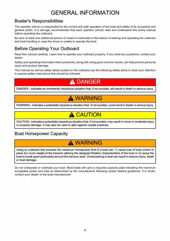
Boat Horsepower Capacity
! WARNINGUsing an outboard that exceeds the maximum horsepower limit of a boat can: 1) cause loss of boat control 2)place too much weight at the transom altering the designed flotation characteristics of the boat or 3) cause theboat to break apart particularly around the transom area. Overpowering a boat can result in serious injury, deathor boat damage.
Do not overpower or overload your boat. Most boats will carry a required capacity plate indicating the maximumacceptable power and load as determined by the manufacturer following certain federal guidelines. If in doubt,contact your dealer or the boat manufacturer.
GENERAL INFORMATION
9
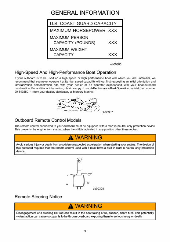
U.S. COAST GUARD CAPACITYMAXIMUM HORSEPOWER XXXMAXIMUM PERSON CAPACITY (POUNDS) XXXMAXIMUM WEIGHT CAPACITY XXX
ob00306
High-Speed And High-Performance Boat OperationIf your outboard is to be used on a high speed or high performance boat with which you are unfamiliar, werecommend that you never operate it at its high speed capability without first requesting an initial orientation andfamiliarization demonstration ride with your dealer or an operator experienced with your boat/outboardcombination. For additional information, obtain a copy of our Hi-Performance Boat Operation booklet (part number90-849250--1) from your dealer, distributor, or Mercury Marine.
ob00307
Outboard Remote Control ModelsThe remote control connected to your outboard must be equipped with a start in neutral only protection device.This prevents the engine from starting when the shift is actuated in any position other than neutral.
! WARNINGAvoid serious injury or death from a sudden unexpected acceleration when starting your engine. The design ofthis outboard requires that the remote control used with it must have a built in start in neutral only protectiondevice.
ob00308
Remote Steering Notice
! WARNINGDisengagement of a steering link rod can result in the boat taking a full, sudden, sharp turn. This potentiallyviolent action can cause occupants to be thrown overboard exposing them to serious injury or death.
GENERAL INFORMATION
10
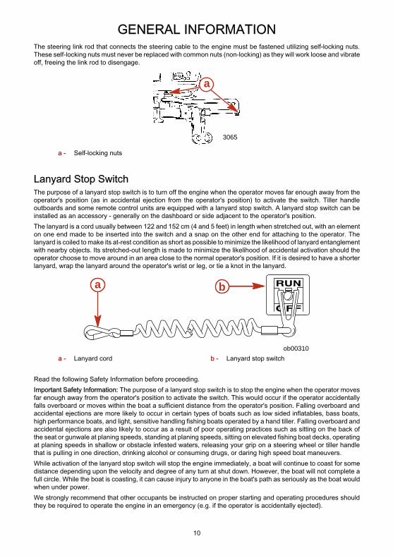
The steering link rod that connects the steering cable to the engine must be fastened utilizing self-locking nuts.These self-locking nuts must never be replaced with common nuts (non-locking) as they will work loose and vibrateoff, freeing the link rod to disengage.
3065
a
a - Self-locking nuts
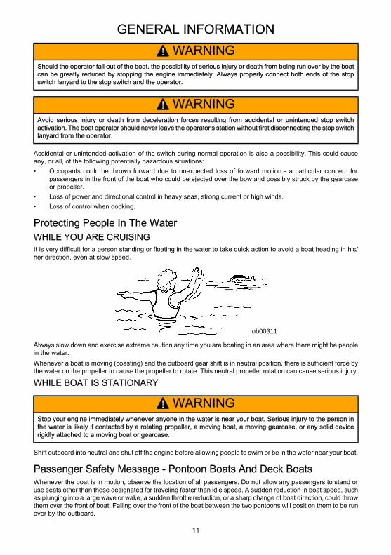
Lanyard Stop SwitchThe purpose of a lanyard stop switch is to turn off the engine when the operator moves far enough away from theoperator's position (as in accidental ejection from the operator's position) to activate the switch. Tiller handleoutboards and some remote control units are equipped with a lanyard stop switch. A lanyard stop switch can beinstalled as an accessory - generally on the dashboard or side adjacent to the operator's position.The lanyard is a cord usually between 122 and 152 cm (4 and 5 feet) in length when stretched out, with an elementon one end made to be inserted into the switch and a snap on the other end for attaching to the operator. Thelanyard is coiled to make its at-rest condition as short as possible to minimize the likelihood of lanyard entanglementwith nearby objects. Its stretched-out length is made to minimize the likelihood of accidental activation should theoperator choose to move around in an area close to the normal operator's position. If it is desired to have a shorterlanyard, wrap the lanyard around the operator's wrist or leg, or tie a knot in the lanyard.
ob00310
a b
a - Lanyard cord b - Lanyard stop switch
Read the following Safety Information before proceeding.Important Safety Information: The purpose of a lanyard stop switch is to stop the engine when the operator movesfar enough away from the operator's position to activate the switch. This would occur if the operator accidentallyfalls overboard or moves within the boat a sufficient distance from the operator's position. Falling overboard andaccidental ejections are more likely to occur in certain types of boats such as low sided inflatables, bass boats,high performance boats, and light, sensitive handling fishing boats operated by a hand tiller. Falling overboard andaccidental ejections are also likely to occur as a result of poor operating practices such as sitting on the back ofthe seat or gunwale at planing speeds, standing at planing speeds, sitting on elevated fishing boat decks, operatingat planing speeds in shallow or obstacle infested waters, releasing your grip on a steering wheel or tiller handlethat is pulling in one direction, drinking alcohol or consuming drugs, or daring high speed boat maneuvers.While activation of the lanyard stop switch will stop the engine immediately, a boat will continue to coast for somedistance depending upon the velocity and degree of any turn at shut down. However, the boat will not complete afull circle. While the boat is coasting, it can cause injury to anyone in the boat's path as seriously as the boat wouldwhen under power.We strongly recommend that other occupants be instructed on proper starting and operating procedures shouldthey be required to operate the engine in an emergency (e.g. if the operator is accidentally ejected).
GENERAL INFORMATION
11
! WARNINGShould the operator fall out of the boat, the possibility of serious injury or death from being run over by the boatcan be greatly reduced by stopping the engine immediately. Always properly connect both ends of the stopswitch lanyard to the stop switch and the operator.
! WARNINGAvoid serious injury or death from deceleration forces resulting from accidental or unintended stop switchactivation. The boat operator should never leave the operator's station without first disconnecting the stop switchlanyard from the operator.
Accidental or unintended activation of the switch during normal operation is also a possibility. This could causeany, or all, of the following potentially hazardous situations:• Occupants could be thrown forward due to unexpected loss of forward motion - a particular concern for
passengers in the front of the boat who could be ejected over the bow and possibly struck by the gearcaseor propeller.
• Loss of power and directional control in heavy seas, strong current or high winds.• Loss of control when docking.
Protecting People In The WaterWHILE YOU ARE CRUISINGIt is very difficult for a person standing or floating in the water to take quick action to avoid a boat heading in his/her direction, even at slow speed.
ob00311
Always slow down and exercise extreme caution any time you are boating in an area where there might be peoplein the water.Whenever a boat is moving (coasting) and the outboard gear shift is in neutral position, there is sufficient force bythe water on the propeller to cause the propeller to rotate. This neutral propeller rotation can cause serious injury.
WHILE BOAT IS STATIONARY
! WARNINGStop your engine immediately whenever anyone in the water is near your boat. Serious injury to the person inthe water is likely if contacted by a rotating propeller, a moving boat, a moving gearcase, or any solid devicerigidly attached to a moving boat or gearcase.
Shift outboard into neutral and shut off the engine before allowing people to swim or be in the water near your boat.
Passenger Safety Message - Pontoon Boats And Deck BoatsWhenever the boat is in motion, observe the location of all passengers. Do not allow any passengers to stand oruse seats other than those designated for traveling faster than idle speed. A sudden reduction in boat speed, suchas plunging into a large wave or wake, a sudden throttle reduction, or a sharp change of boat direction, could throwthem over the front of boat. Falling over the front of the boat between the two pontoons will position them to be runover by the outboard.
GENERAL INFORMATION
12
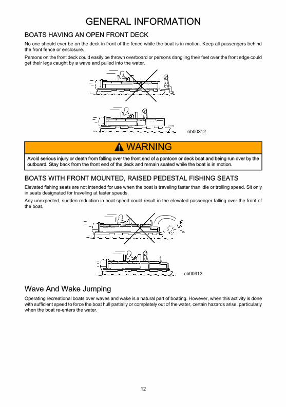
BOATS HAVING AN OPEN FRONT DECKNo one should ever be on the deck in front of the fence while the boat is in motion. Keep all passengers behindthe front fence or enclosure.Persons on the front deck could easily be thrown overboard or persons dangling their feet over the front edge couldget their legs caught by a wave and pulled into the water.
ob00312
! WARNINGAvoid serious injury or death from falling over the front end of a pontoon or deck boat and being run over by theoutboard. Stay back from the front end of the deck and remain seated while the boat is in motion.
BOATS WITH FRONT MOUNTED, RAISED PEDESTAL FISHING SEATSElevated fishing seats are not intended for use when the boat is traveling faster than idle or trolling speed. Sit onlyin seats designated for traveling at faster speeds.Any unexpected, sudden reduction in boat speed could result in the elevated passenger falling over the front ofthe boat.
ob00313
Wave And Wake JumpingOperating recreational boats over waves and wake is a natural part of boating. However, when this activity is donewith sufficient speed to force the boat hull partially or completely out of the water, certain hazards arise, particularlywhen the boat re-enters the water.
GENERAL INFORMATION
13
ob00314
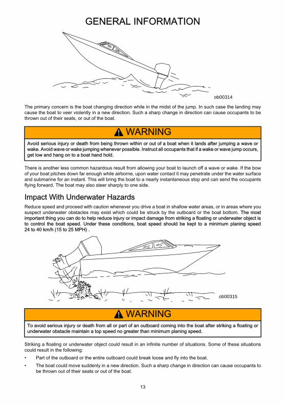
The primary concern is the boat changing direction while in the midst of the jump. In such case the landing maycause the boat to veer violently in a new direction. Such a sharp change in direction can cause occupants to bethrown out of their seats, or out of the boat.
! WARNINGAvoid serious injury or death from being thrown within or out of a boat when it lands after jumping a wave orwake. Avoid wave or wake jumping whenever possible. Instruct all occupants that if a wake or wave jump occurs,get low and hang on to a boat hand hold.
There is another less common hazardous result from allowing your boat to launch off a wave or wake. If the bowof your boat pitches down far enough while airborne, upon water contact it may penetrate under the water surfaceand submarine for an instant. This will bring the boat to a nearly instantaneous stop and can send the occupantsflying forward. The boat may also steer sharply to one side.
Impact With Underwater HazardsReduce speed and proceed with caution whenever you drive a boat in shallow water areas, or in areas where yoususpect underwater obstacles may exist which could be struck by the outboard or the boat bottom. The mostimportant thing you can do to help reduce injury or impact damage from striking a floating or underwater object isto control the boat speed. Under these conditions, boat speed should be kept to a minimum planing speed24 to 40 km/h (15 to 25 MPH) .
ob00315
! WARNINGTo avoid serious injury or death from all or part of an outboard coming into the boat after striking a floating orunderwater obstacle maintain a top speed no greater than minimum planing speed.
Striking a floating or underwater object could result in an infinite number of situations. Some of these situationscould result in the following:• Part of the outboard or the entire outboard could break loose and fly into the boat.• The boat could move suddenly in a new direction. Such a sharp change in direction can cause occupants to
be thrown out of their seats or out of the boat.
GENERAL INFORMATION
14
• A rapid reduction in speed. This will cause occupants to be thrown forward, or even out of the boat.• Impact damage to the outboard and/or boat.Keep in mind, the most important thing you can do to help reduce injury or impact damage during an impact iscontrol the boat speed. Boat speed should be kept to a minimum planing speed when driving in waters known tohave underwater obstacles.After striking a submerged object, stop the engine as soon as possible and inspect it for any broken or loose parts.If damage is present or suspected, the outboard should be taken to an authorized dealer for a thorough inspectionand necessary repair.The boat should also be checked for any hull fractures, transom fractures, or water leaks.Operating a damaged outboard could cause additional damage to other parts of the outboard, or could affect controlof the boat. If continued running is necessary, do so at greatly reduced speeds.
! WARNINGAvoid serious injury or death from loss of boat control. Continued boating with major impact damage can resultin sudden outboard component failure with or without subsequent impacts. Have the outboard thoroughlyinspected and any necessary repairs made.
Safety Instructions For Hand Tilled OutboardsNo person or cargo should occupy the area directly in front of the outboard while the boat is in motion. If anunderwater obstacle is struck, the outboard will tilt up and could seriously injure anyone occupying this area.
MODELS WITH CLAMP SCREWS:Some outboards come with transom bracket clamp screws. The use of clamp bracket screws alone, is insufficientto properly and safely secure the outboard to the transom. Proper installation of the outboard includes bolting theengine to the boat through the transom. Refer to Installation - Installing Outboard for more complete installationinformation.
! WARNINGAvoid serious injury or death from being struck by a disconnected outboard. Do not accelerate above idle speedin water suspected of containing underwater obstacles if the outboard is not attached to the transom correctly.
If an obstacle is struck at planing speed and the outboard is not securely fastened to the transom, it is possible theoutboard could lift off the transom and land in the boat.
Exhaust EmissionsBE ALERT TO CARBON MONOXIDE POISONINGCarbon monoxide is present in the exhaust fumes of all internal combustion engines. This includes the outboards,sterndrives and inboard engines that propel boats, as well as the generators that power various boat accessories.Carbon monoxide is a deadly gas that is odorless, colorless and tasteless.Early symptoms of carbon monoxide poisoning which should not be confused with seasickness or intoxication,include headache, dizziness, drowsiness, and nausea.
! WARNINGAvoid the combination of a running engine and poor ventilation. Prolonged exposure to carbon monoxide insufficient concentration can lead to unconsciousness, brain damage, or death.
GOOD VENTILATIONVentilate passenger area, open side curtains, or forward hatches to remove fumes.
GENERAL INFORMATION
15
ob00316
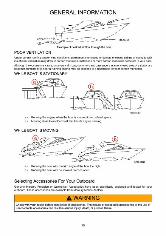
Example of desired air flow through the boat.
POOR VENTILATIONUnder certain running and/or wind conditions, permanently enclosed or canvas enclosed cabins or cockpits withinsufficient ventilation may draw in carbon monoxide. Install one or more carbon monoxide detectors in your boat.Although the occurrence is rare, on a very calm day, swimmers and passengers in an enclosed area of a stationaryboat that contains or is near a running engine may be exposed to a hazardous level of carbon monoxide.
WHILE BOAT IS STATIONARY
ob00317
ab
a - Running the engine when the boat is moored in a confined space.b - Mooring close to another boat that has its engine running.
WHILE BOAT IS MOVING
ob00318
a b
a - Running the boat with the trim angle of the bow too high.b - Running the boat with no forward hatches open.
Selecting Accessories For Your OutboardGenuine Mercury Precision or Quicksilver Accessories have been specifically designed and tested for youroutboard. These accessories are available from Mercury Marine dealers.
! WARNINGCheck with your dealer before installation of accessories. The misuse of acceptable accessories or the use ofunacceptable accessories can result in serious injury, death, or product failure.
GENERAL INFORMATION
16
Some accessories not manufactured or sold by Mercury Marine are not designed to be safely used with youroutboard or outboard operating system. Acquire and read the installation, operation, and maintenance manualsfor all your selected accessories.
Safe Boating SuggestionsIn order to safely enjoy the waterways, familiarize yourself with local and other governmental boating regulationsand restrictions, and consider the following suggestions.Use flotation devices. Have an approved personal flotation device of suitable size for each person aboard (it is thelaw) and have it readily accessible.Do not overload your boat. Most boats are rated and certified for maximum load (weight) capacities (refer to yourboat capacity plate). If in doubt, contact your dealer or the boats manufacturer.Perform safety checks and required maintenance. Follow a regular schedule and ensure that all repairs are properlymade.Know and obey all nautical rules and laws of the waterways. Boat operators should complete a boating safetycourse. Courses are offered in the U.S.A. by 1) The U.S. Coast Guard Auxiliary, 2) The Power Squadron, 3) TheRed Cross and 4) your state boating law enforcement agency. Inquiries may be made to the Boating Hotline,1-800-368-5647 or the Boat U.S. Foundation information number 1-800-336-BOAT.Make sure everyone in the boat is properly seated. Do not allow anyone to sit or ride on any part of the boat thatwas not intended for such use. This includes the back of seats, gunwales, transom, bow, decks, raised fishingseats, any rotating fishing seat; or anywhere that an unexpected acceleration, sudden stopping, unexpected lossof boat control, or sudden boat movement could cause a person to be thrown overboard or into the boat.Never be under the influence of alcohol or drugs while boating (it is the law). Alcohol or drug use impairs yourjudgment and greatly reduces your ability to react quickly.Prepare other boat operators. Instruct at least one other person on board in the basics of starting and operatingthe outboard, and boat handling, in case the driver becomes disabled or falls overboard.Passenger boarding. Stop the engine whenever passengers are boarding, unloading, or are near the back (stern)of the boat. Just shifting the outboard into neutral is not sufficient.Be alert. The operator of the boat is responsible by law to maintain a proper lookout by sight and hearing. Theoperator must have an unobstructed view particularly to the front. No passengers, load, or fishing seats shouldblock the operators view when operating the boat above idle speed.Never drive your boat directly behind a water skier in case the skier falls. As an example, your boat traveling at40 km/h (25 MPH) will overtake a fallen skier 61 m (200 ft.) in front of you in 5 seconds.Watch fallen skiers. When using your boat for water skiing or similar activities, always keep a fallen or down skieron the operator's side of the boat while returning to assist the skier. The operator should always have the downskier in sight and never back up to the skier or anyone in the water.Report accidents. Boat operators are required by law to file a Boating Accident Report with their state boating lawenforcement agency when their boat is involved in certain boating accidents. A boating accident must be reportedif 1) there is loss of life or probable loss of life, 2) there is personal injury requiring medical treatment beyond firstaid, 3) there is damage to boats or other property where the damage value exceeds $500.00 or 4) there is completeloss of the boat. Seek further assistance from local law enforcement.
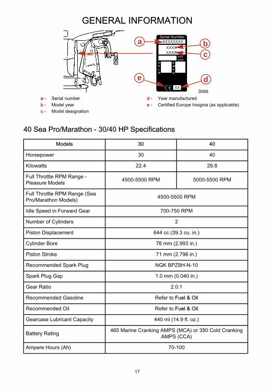
Recording Serial NumberIt is important to record this number for future reference. The serial number is located on the outboard as shown.
GENERAL INFORMATION
17
Serial Number
HPLB
XXXX
XX
XXXXXXXX
XXXX
a bc
de
KWKG
MAXRPM
3066a - Serial numberb - Model yearc - Model designation
d - Year manufacturede - Certified Europe Insignia (as applicable)
40 Sea Pro/Marathon - 30/40 HP Specifications
Models 30 40
Horsepower 30 40
Kilowatts 22.4 29.8
Full Throttle RPM Range -Pleasure Models 4500-5500 RPM 5000-5500 RPM
Full Throttle RPM Range (SeaPro/Marathon Models) 4500-5500 RPM
Idle Speed in Forward Gear 700-750 RPM
Number of Cylinders 2
Piston Displacement 644 cc (39.3 cu. in.)
Cylinder Bore 76 mm (2.993 in.)
Piston Stroke 71 mm (2.796 in.)
Recommended Spark Plug NGK BPZ8H-N-10
Spark Plug Gap 1.0 mm (0.040 in.)
Gear Ratio 2.0:1
Recommended Gasoline Refer to Fuel & Oil
Recommended Oil Refer to Fuel & Oil
Gearcase Lubricant Capacity 440 ml (14.9 fl. oz.)
Battery Rating 465 Marine Cranking AMPS (MCA) or 350 Cold CrankingAMPS (CCA)
Ampere Hours (Ah) 70-100
GENERAL INFORMATION
18
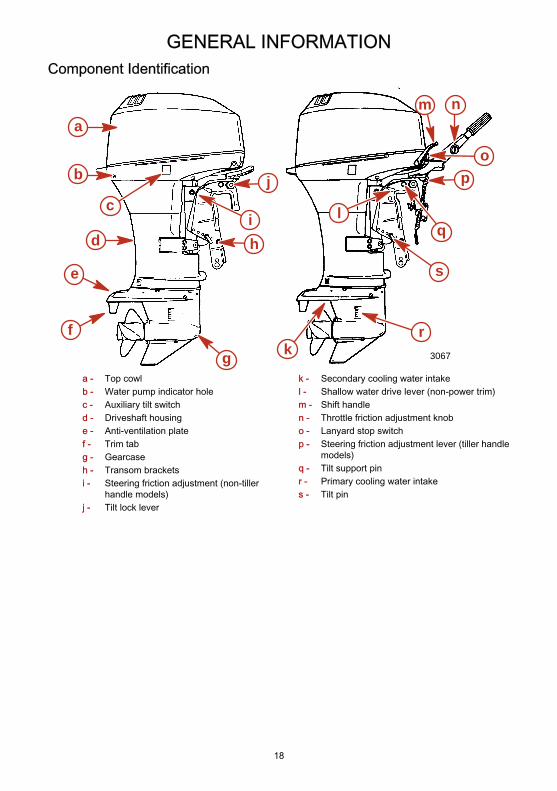
Component Identification
3067
a
b
d
e
f
g
hi
j
k
l
m n
p
qc
o
r
s
a - Top cowlb - Water pump indicator holec - Auxiliary tilt switchd - Driveshaft housinge - Anti-ventilation platef - Trim tabg - Gearcaseh - Transom bracketsi - Steering friction adjustment (non-tiller
handle models)j - Tilt lock lever
k - Secondary cooling water intakel - Shallow water drive lever (non-power trim)m - Shift handlen - Throttle friction adjustment knobo - Lanyard stop switchp - Steering friction adjustment lever (tiller handle
models)q - Tilt support pinr - Primary cooling water intakes - Tilt pin
GENERAL INFORMATION
19
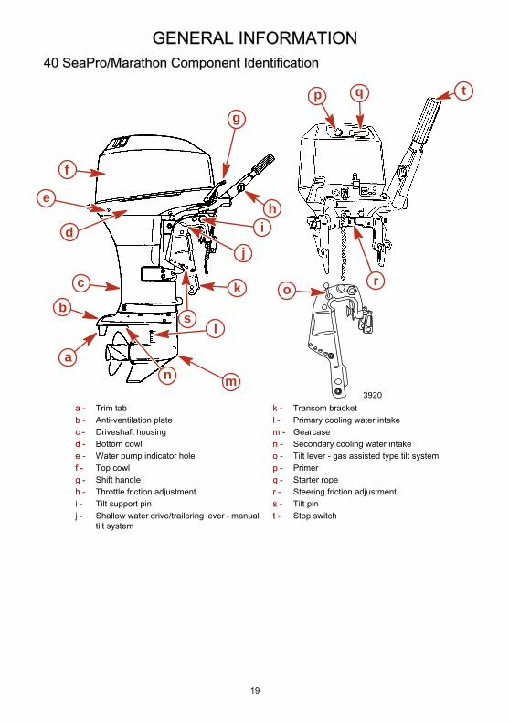
40 SeaPro/Marathon Component Identification
a
b
c
d
e
f
g
hi
j
k
l
mn
o
p q
r
3920
s
t
a - Trim tabb - Anti-ventilation platec - Driveshaft housingd - Bottom cowle - Water pump indicator holef - Top cowlg - Shift handleh - Throttle friction adjustmenti - Tilt support pinj - Shallow water drive/trailering lever - manual
tilt system
k - Transom bracketl - Primary cooling water intakem - Gearcasen - Secondary cooling water intakeo - Tilt lever - gas assisted type tilt systemp - Primerq - Starter roper - Steering friction adjustments - Tilt pint - Stop switch
INSTALLATION
20
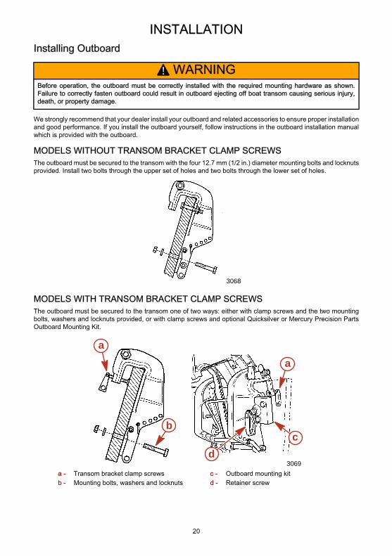
Installing Outboard
! WARNINGBefore operation, the outboard must be correctly installed with the required mounting hardware as shown.Failure to correctly fasten outboard could result in outboard ejecting off boat transom causing serious injury,death, or property damage.
We strongly recommend that your dealer install your outboard and related accessories to ensure proper installationand good performance. If you install the outboard yourself, follow instructions in the outboard installation manualwhich is provided with the outboard.
MODELS WITHOUT TRANSOM BRACKET CLAMP SCREWSThe outboard must be secured to the transom with the four 12.7 mm (1/2 in.) diameter mounting bolts and locknutsprovided. Install two bolts through the upper set of holes and two bolts through the lower set of holes.
3068
MODELS WITH TRANSOM BRACKET CLAMP SCREWSThe outboard must be secured to the transom one of two ways: either with clamp screws and the two mountingbolts, washers and locknuts provided, or with clamp screws and optional Quicksilver or Mercury Precision PartsOutboard Mounting Kit.
3069
a
bc
d
a
a - Transom bracket clamp screwsb - Mounting bolts, washers and locknuts
c - Outboard mounting kitd - Retainer screw
INSTALLATION
21
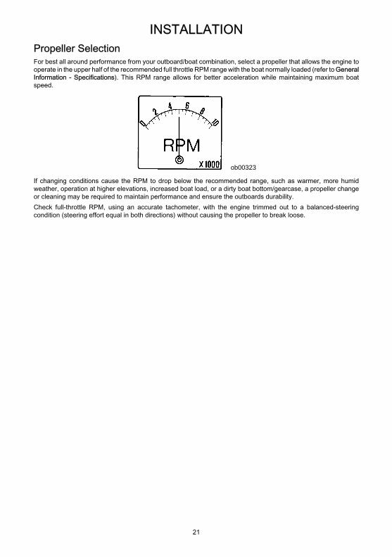
Propeller SelectionFor best all around performance from your outboard/boat combination, select a propeller that allows the engine tooperate in the upper half of the recommended full throttle RPM range with the boat normally loaded (refer to GeneralInformation - Specifications). This RPM range allows for better acceleration while maintaining maximum boatspeed.
ob00323
If changing conditions cause the RPM to drop below the recommended range, such as warmer, more humidweather, operation at higher elevations, increased boat load, or a dirty boat bottom/gearcase, a propeller changeor cleaning may be required to maintain performance and ensure the outboards durability.Check full-throttle RPM, using an accurate tachometer, with the engine trimmed out to a balanced-steeringcondition (steering effort equal in both directions) without causing the propeller to break loose.
TRANSPORTING
22
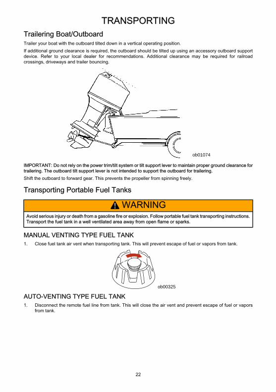
Trailering Boat/OutboardTrailer your boat with the outboard tilted down in a vertical operating position.If additional ground clearance is required, the outboard should be tilted up using an accessory outboard supportdevice. Refer to your local dealer for recommendations. Additional clearance may be required for railroadcrossings, driveways and trailer bouncing.
ob01074
IMPORTANT: Do not rely on the power trim/tilt system or tilt support lever to maintain proper ground clearance fortrailering. The outboard tilt support lever is not intended to support the outboard for trailering.Shift the outboard to forward gear. This prevents the propeller from spinning freely.
Transporting Portable Fuel Tanks
! WARNINGAvoid serious injury or death from a gasoline fire or explosion. Follow portable fuel tank transporting instructions.Transport the fuel tank in a well ventilated area away from open flame or sparks.
MANUAL VENTING TYPE FUEL TANK1. Close fuel tank air vent when transporting tank. This will prevent escape of fuel or vapors from tank.
ob00325
AUTO-VENTING TYPE FUEL TANK1. Disconnect the remote fuel line from tank. This will close the air vent and prevent escape of fuel or vapors
from tank.
TRANSPORTING
23
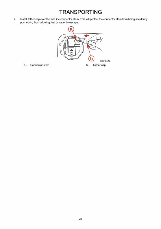
2. Install tether cap over the fuel line connector stem. This will protect the connector stem from being accidentlypushed-in, thus, allowing fuel or vapor to escape.
F
ob00326
a
ba - Connector stem b - Tether cap
FUEL & OIL
24
Gasoline RecommendationsUNITED STATES AND CANADAUse a major brand of automotive unleaded gasoline with a minimum posted octane rating of 87. Mid-gradeautomotive gasolines that contain fuel injector cleaner are preferred for added internal engine cleanliness. Leadedgasoline is not recommended.
INTERNATIONALUse a major brand of automotive unleaded gasoline with a minimum posted octane rating of 90RON. Automotivegasolines that contain fuel injector cleaner are preferred for added internal engine cleanliness. Leaded gasoline isacceptable in areas where unleaded gasoline is not available.
USING REFORMULATED (OXYGENATED) FUELS - UNITED STATES ONLYThis type of fuel is required in certain areas of the United States. The two types of reformulated ingredients in thesefuels are alcohol (Ethanol) or Ether (MTBE or ETBE). If Ethanol is the oxygenates that is used in the gasoline, referto Alcohol in Gasoline.These reformulated fuels are acceptable for use in the Mercury engine.
ALCOHOL IN GASOLINEWe do not recommend the use of gasoline which contains alcohol because of the possible adverse effect thealcohol may have on the fuel system. In general, if only gasoline containing alcohol is available, it must not containmore than 10% ethanol or 5% methanol, and the addition of a water separating fuel filter is recommended.If gasoline containing alcohol is used or if you suspect the presence of alcohol in your gasoline, increase yourinspection of the fuel system, visually checking for fuel leaks or abnormalities.Gasoline containing alcohol may cause the following problems to your outboard and fuel system:• Corrosion of metal parts• Deterioration of elastomers and plastic parts• Wear and damage of internal engine parts• Starting and operating difficulties• Vapor lock or fuel starvationSome of these adverse effects are due to the tendency of gasoline containing alcohol to absorb moisture from theair, resulting in a phase of water and alcohol which separates from the gasoline in the fuel tank.The adverse effects of alcohol are more severe with methanol and are worse with increasing content of alcohol.
Oil Recommendation
Recommended Oil Mercury or Quicksilver Premium 2-Cycle TC-W3 Outboard Oil
IMPORTANT: Oil must be NMMA certified TC-W3 2-Cycle oil.Mercury or Quicksilver Premium TC-W3 2-Cycle oil is recommended for this engine. For added protection andlubrication, Mercury or Quicksilver Premium Plus TC-W3 2-Cycle oil is recommended. If Mercury or Quicksilveroutboard oil is not available, substitute another brand of 2-cycle outboard oil that is NMMA Certified TC-W3. Severeengine damage may result from use of an inferior oil.
Fuel and Oil RatioMODELS WITH OIL INJECTIONUse a 50:1 (2%) gasoline/oil mixture in the first tank of fuel. Follow the table below for mixing ratios. Use of thisfuel mixture combined with oil from the oil injection system will supply adequate lubrication during engine break-in.After the break-in fuel mixture is used up, it is no longer necessary to add oil with the gasoline.NOTE: At the end of the break-in period, visually check to see if the oil level in the oil injection system has dropped.Oil usage indicates the oil injection system is functioning correctly.
FUEL & OIL
25
GASOLINE/OIL MIXING RATIO CHART
Gas/Oil Ratio 3.8 liters (1 gal.) gas 11.5 liters (3 gal.) gas 23 liters (6 gal.) gas
50:1 (2%) 89 ml (3 fl. oz.) oil 237 ml (8 fl. oz.) oil 473 ml (16 fl. oz.) oil
MODELS WITHOUT OIL INJECTIONUse a 25:1 (4%) gasoline/oil mixture in the first tank of fuel.After the break-in fuel mixture is used up, use a 50:1 (2%) gasoline/oil mixture. Follow the table for mixing ratios.
GASOLINE/OIL MIXING RATIO CHART
Gas/Oil Ratio 3.8 liters (1 gal.) gas 11.5 liters (3 gal.) gas 23 liters (6 gal.) gas
25:1 (4%) 148 ml (5 fl. oz.) oil 473 ml (16 fl. oz.) oil 946 ml (32 fl. oz.) oil
50:1 (2%) 89 ml (3 fl. oz.) oil 237 ml (8 fl. oz.) oil 473 ml (16 fl. oz.) oil
Mixing Fuel and OilPortable Tank - Pour 4 liters (1 gallon) of gasoline into tank. Add the correct amount of oil and mix thoroughly. Addthe remainder of gasoline.Built-in Tank - Using a funnel, pour the correct amount of oil slowly with the gasoline as tank is filled.
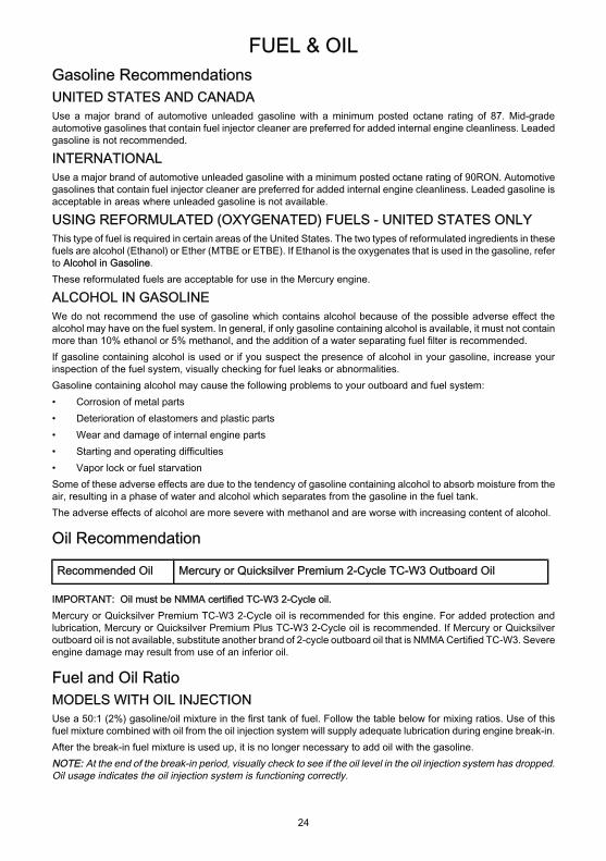
Filling Oil Injection System1. Place outboard in a vertical operating position. Check oil level using the sight gauge in front of the outboard.
3100
a
b
a - Full level b - Add level
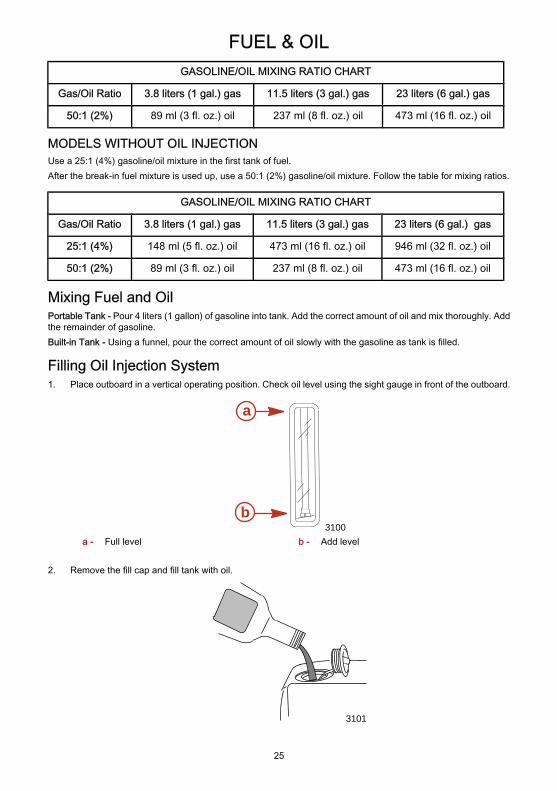
2. Remove the fill cap and fill tank with oil.
3101
FUEL & OIL
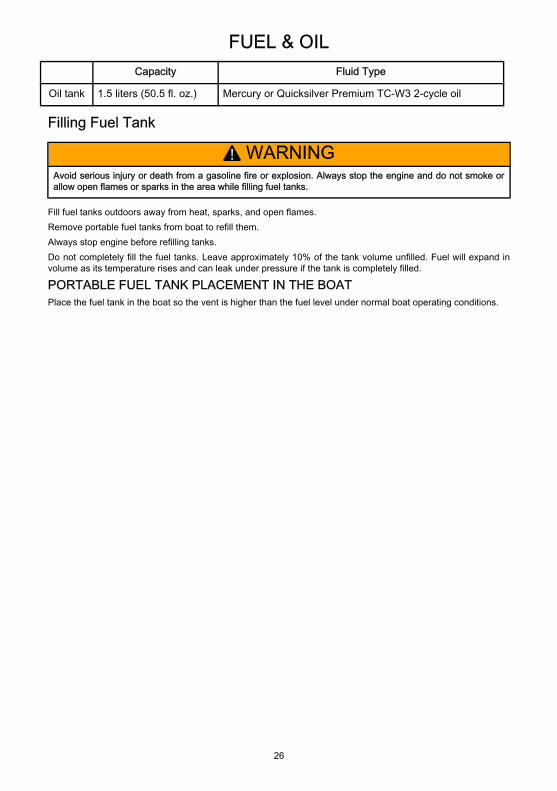
26
Capacity Fluid Type
Oil tank 1.5 liters (50.5 fl. oz.) Mercury or Quicksilver Premium TC-W3 2-cycle oil
Filling Fuel Tank
! WARNINGAvoid serious injury or death from a gasoline fire or explosion. Always stop the engine and do not smoke orallow open flames or sparks in the area while filling fuel tanks.
Fill fuel tanks outdoors away from heat, sparks, and open flames.Remove portable fuel tanks from boat to refill them.Always stop engine before refilling tanks.Do not completely fill the fuel tanks. Leave approximately 10% of the tank volume unfilled. Fuel will expand involume as its temperature rises and can leak under pressure if the tank is completely filled.
PORTABLE FUEL TANK PLACEMENT IN THE BOATPlace the fuel tank in the boat so the vent is higher than the fuel level under normal boat operating conditions.
FEATURES & CONTROLS
27
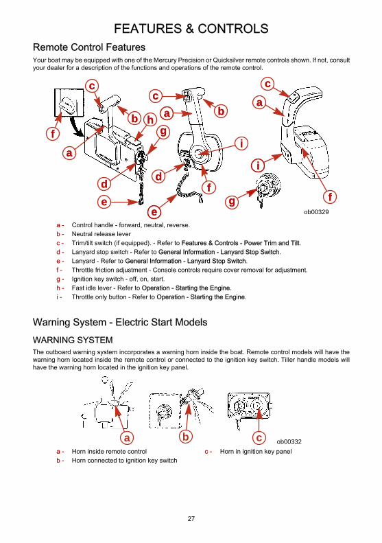
Remote Control FeaturesYour boat may be equipped with one of the Mercury Precision or Quicksilver remote controls shown. If not, consultyour dealer for a description of the functions and operations of the remote control.
ee
aa
dd dd
eeffgg
aa
bbff
cc
gghh
bbcc
aa
ff
ii
cc
ii
ob00329
a - Control handle - forward, neutral, reverse.b - Neutral release leverc - Trim/tilt switch (if equipped). - Refer to Features & Controls - Power Trim and Tilt.d - Lanyard stop switch - Refer to General Information - Lanyard Stop Switch.e - Lanyard - Refer to General Information - Lanyard Stop Switch.f - Throttle friction adjustment - Console controls require cover removal for adjustment.g - Ignition key switch - off, on, start.h - Fast idle lever - Refer to Operation - Starting the Engine.i - Throttle only button - Refer to Operation - Starting the Engine.
Warning System - Electric Start ModelsWARNING SYSTEMThe outboard warning system incorporates a warning horn inside the boat. Remote control models will have thewarning horn located inside the remote control or connected to the ignition key switch. Tiller handle models willhave the warning horn located in the ignition key panel.
a b c ob00332a - Horn inside remote controlb - Horn connected to ignition key switch
c - Horn in ignition key panel
FEATURES & CONTROLS
28
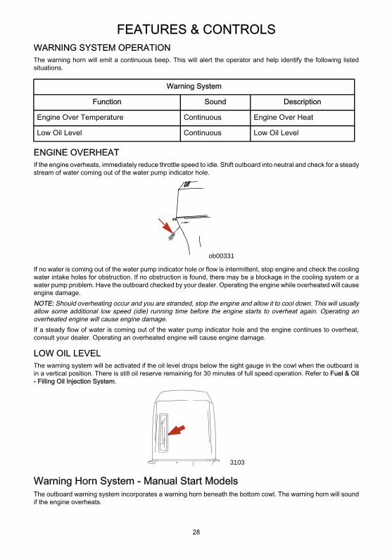
WARNING SYSTEM OPERATIONThe warning horn will emit a continuous beep. This will alert the operator and help identify the following listedsituations.
Warning System
Function Sound Description
Engine Over Temperature Continuous Engine Over Heat
Low Oil Level Continuous Low Oil Level
ENGINE OVERHEATIf the engine overheats, immediately reduce throttle speed to idle. Shift outboard into neutral and check for a steadystream of water coming out of the water pump indicator hole.
ob00331
If no water is coming out of the water pump indicator hole or flow is intermittent, stop engine and check the coolingwater intake holes for obstruction. If no obstruction is found, there may be a blockage in the cooling system or awater pump problem. Have the outboard checked by your dealer. Operating the engine while overheated will causeengine damage.NOTE: Should overheating occur and you are stranded, stop the engine and allow it to cool down. This will usuallyallow some additional low speed (idle) running time before the engine starts to overheat again. Operating anoverheated engine will cause engine damage.If a steady flow of water is coming out of the water pump indicator hole and the engine continues to overheat,consult your dealer. Operating an overheated engine will cause engine damage.
LOW OIL LEVELThe warning system will be activated if the oil level drops below the sight gauge in the cowl when the outboard isin a vertical position. There is still oil reserve remaining for 30 minutes of full speed operation. Refer to Fuel & Oil- Filling Oil Injection System.
3103
Warning Horn System - Manual Start ModelsThe outboard warning system incorporates a warning horn beneath the bottom cowl. The warning horn will soundif the engine overheats.
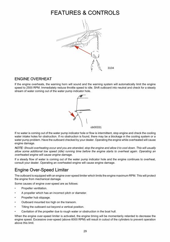
FEATURES & CONTROLS
29
3104
ENGINE OVERHEATIf the engine overheats, the warning horn will sound and the warning system will automatically limit the enginespeed to 2500 RPM. Immediately reduce throttle speed to idle. Shift outboard into neutral and check for a steadystream of water coming out of the water pump indicator hole.
ob00331
If no water is coming out of the water pump indicator hole or flow is intermittent, stop engine and check the coolingwater intake holes for obstruction. If no obstruction is found, there may be a blockage in the cooling system or awater pump problem. Have the outboard checked by your dealer. Operating the engine while overheated will causeengine damage.NOTE: Should overheating occur and you are stranded, stop the engine and allow it to cool down. This will usuallyallow some additional low speed (idle) running time before the engine starts to overheat again. Operating anoverheated engine will cause engine damage.If a steady flow of water is coming out of the water pump indicator hole and the engine continues to overheat,consult your dealer. Operating an overheated engine will cause engine damage.
Engine Over-Speed LimiterThe outboard is equipped with an engine over-speed limiter which limits the engine maximum RPM. This will protectthe engine from mechanical damage.Some causes of engine over-speed are as follows:• Propeller ventilation.• A propeller which has an incorrect pitch or diameter.• Propeller hub slippage.• Outboard mounted too high on the transom.• Tilting the outboard out beyond a vertical position.• Cavitation of the propeller due to rough water or obstruction in the boat hull.When the engine over-speed limiter is activated, the engine timing will be momentarily retarded to decrease theengine speed. Excessive over-speed (above 6000 RPM) will result in cutout of the cylinders to prevent operationabove this limit.
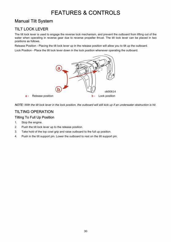
FEATURES & CONTROLS
30
Manual Tilt SystemTILT LOCK LEVERThe tilt lock lever is used to engage the reverse lock mechanism, and prevent the outboard from lifting out of thewater when operating in reverse gear due to reverse propeller thrust. The tilt lock lever can be placed in twopositions as follows.Release Position - Placing the tilt lock lever up in the release position will allow you to tilt up the outboard.Lock Position - Place the tilt lock lever down in the lock position whenever operating the outboard.
ob00614
a
ba - Release position b - Lock position
NOTE: With the tilt lock lever in the lock position, the outboard will still kick up if an underwater obstruction is hit.
TILTING OPERATIONTilting To Full Up Position1. Stop the engine.2. Push the tilt lock lever up to the release position.3. Take hold of the top cowl grip and raise outboard to the full up position.4. Push in the tilt support pin. Lower the outboard to rest on the tilt support pin.
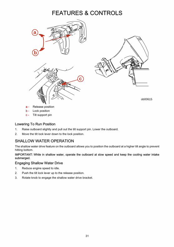
FEATURES & CONTROLS
31
ob00615
a
b
c
a - Release positionb - Lock positionc - Tilt support pin
Lowering To Run Position1. Raise outboard slightly and pull out the tilt support pin. Lower the outboard.2. Move the tilt lock lever down to the lock position.
SHALLOW WATER OPERATIONThe shallow water drive feature on the outboard allows you to position the outboard at a higher tilt angle to preventhitting bottom.IMPORTANT: While in shallow water, operate the outboard at slow speed and keep the cooling water intakesubmerged.
Engaging Shallow Water Drive1. Reduce engine speed to idle.2. Push the tilt lock lever up to the release position.3. Rotate knob to engage the shallow water drive bracket.
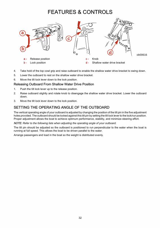
FEATURES & CONTROLS
32
ob00616
a
b
c
da - Release positionb - Lock position
c - Knobd - Shallow water drive bracket
4. Take hold of the top cowl grip and raise outboard to enable the shallow water drive bracket to swing down.5. Lower the outboard to rest on the shallow water drive bracket.6. Move the tilt lock lever down to the lock position.
Releasing Outboard From Shallow Water Drive Position1. Push the tilt lock lever up to the release position.2. Raise outboard slightly and rotate knob to disengage the shallow water drive bracket. Lower the outboard
down.3. Move the tilt lock lever down to the lock position.
SETTING THE OPERATING ANGLE OF THE OUTBOARDThe vertical operating angle of your outboard is adjusted by changing the position of the tilt pin in the five adjustmentholes provided. The outboard should be locked against this tilt pin by setting the tilt lock lever to the lock/run position.Proper adjustment allows the boat to achieve optimum performance, stability, and minimize steering effort.NOTE: Refer to the following lists when adjusting the operating angle of your outboard.The tilt pin should be adjusted so the outboard is positioned to run perpendicular to the water when the boat isrunning at full speed. This allows the boat to be driven parallel to the water.Arrange passengers and load in the boat so the weight is distributed evenly.
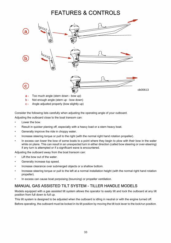
FEATURES & CONTROLS
33
ob00613
a
b
c
a - Too much angle (stern down - bow up)b - Not enough angle (stern up - bow down)c - Angle adjusted properly (bow slightly up)
Consider the following lists carefully when adjusting the operating angle of your outboard.Adjusting the outboard close to the boat transom can:• Lower the bow.• Result in quicker planing off, especially with a heavy load or a stern heavy boat.• Generally improve the ride in choppy water.• Increase steering torque or pull to the right (with the normal right hand rotation propeller).• In excess can lower the bow of some boats to a point where they begin to plow with their bow in the water
while on plane. This can result in an unexpected turn in either direction (called bow steering or over-steering)if any turn is attempted or if a significant wave is encountered.
Adjusting the outboard away from the boat transom can:• Lift the bow out of the water.• Generally increase top speed.• Increase clearance over submerged objects or a shallow bottom.• Increase steering torque or pull to the left at a normal installation height (with the normal right hand rotation
propeller).• In excess can cause boat porpoising (bouncing) or propeller ventilation.
MANUAL GAS ASSISTED TILT SYSTEM - TILLER HANDLE MODELSModels equipped with a gas assisted tilt system allows the operator to easily tilt and lock the outboard at any tiltposition from full down to full up.This tilt system is designed to be adjusted when the outboard is idling in neutral or with the engine turned off.Before operating, the outboard must be locked in its tilt position by moving the tilt lock lever to the lock/run position.
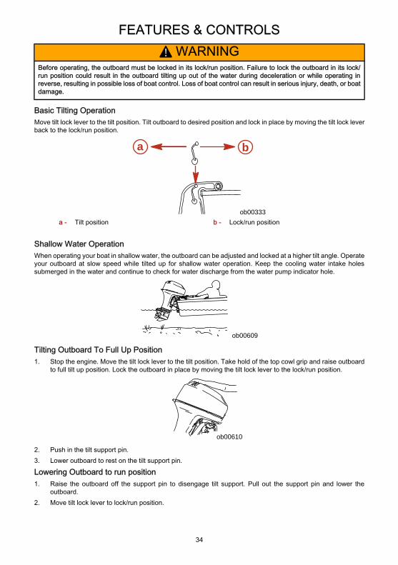
FEATURES & CONTROLS
34
! WARNINGBefore operating, the outboard must be locked in its lock/run position. Failure to lock the outboard in its lock/run position could result in the outboard tilting up out of the water during deceleration or while operating inreverse, resulting in possible loss of boat control. Loss of boat control can result in serious injury, death, or boatdamage.
Basic Tilting OperationMove tilt lock lever to the tilt position. Tilt outboard to desired position and lock in place by moving the tilt lock leverback to the lock/run position.
a b
ob00333a - Tilt position b - Lock/run position
Shallow Water OperationWhen operating your boat in shallow water, the outboard can be adjusted and locked at a higher tilt angle. Operateyour outboard at slow speed while tilted up for shallow water operation. Keep the cooling water intake holessubmerged in the water and continue to check for water discharge from the water pump indicator hole.
ob00609
Tilting Outboard To Full Up Position1. Stop the engine. Move the tilt lock lever to the tilt position. Take hold of the top cowl grip and raise outboard
to full tilt up position. Lock the outboard in place by moving the tilt lock lever to the lock/run position.
ob00610
2. Push in the tilt support pin.3. Lower outboard to rest on the tilt support pin.
Lowering Outboard to run position1. Raise the outboard off the support pin to disengage tilt support. Pull out the support pin and lower the
outboard.2. Move tilt lock lever to lock/run position.
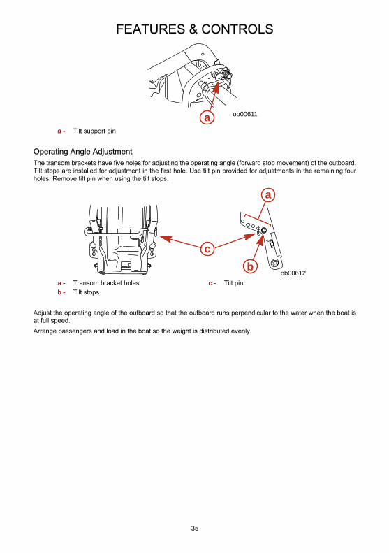
FEATURES & CONTROLS
35
ob00611aa - Tilt support pin
Operating Angle AdjustmentThe transom brackets have five holes for adjusting the operating angle (forward stop movement) of the outboard.Tilt stops are installed for adjustment in the first hole. Use tilt pin provided for adjustments in the remaining fourholes. Remove tilt pin when using the tilt stops.
ob00612
a
bc
a - Transom bracket holesb - Tilt stops
c - Tilt pin
Adjust the operating angle of the outboard so that the outboard runs perpendicular to the water when the boat isat full speed.Arrange passengers and load in the boat so the weight is distributed evenly.
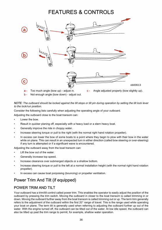
FEATURES & CONTROLS
36
ob00613
a
b
c
a - Too much angle (bow up) - adjust in.b - Not enough angle (bow down) - adjust out.
c - Angle adjusted properly (bow slightly up).
NOTE: The outboard should be locked against the tilt stops or tilt pin during operation by setting the tilt lock leverto the lock/run position.Consider the following lists carefully when adjusting the operating angle of your outboard.Adjusting the outboard close to the boat transom can:• Lower the bow.• Result in quicker planing off, especially with a heavy load or a stern heavy boat.• Generally improve the ride in choppy water.• Increase steering torque or pull to the right (with the normal right hand rotation propeller).• In excess can lower the bow of some boats to a point where they begin to plow with their bow in the water
while on plane. This can result in an unexpected turn in either direction (called bow steering or over-steering)if any turn is attempted or if a significant wave is encountered.
Adjusting the outboard away from the boat transom can:• Lift the bow out of the water.• Generally increase top speed.• Increase clearance over submerged objects or a shallow bottom.• Increase steering torque or pull to the left at a normal installation height (with the normal right hand rotation
propeller).• In excess can cause boat porpoising (bouncing) or propeller ventilation.
Power Trim And Tilt (if equipped)POWER TRIM AND TILTYour outboard has a trim/tilt control called power trim. This enables the operator to easily adjust the position of theoutboard by pressing the trim switch. Moving the outboard in closer to the boat transom is called trimming in ordown. Moving the outboard further away from the boat transom is called trimming out or up. The term trim generallyrefers to the adjustment of the outboard within the first 20° range of travel. This is the range used while operatingyour boat on plane. The term tilt is generally used when referring to adjusting the outboard further up out of thewater. With the engine turned off, the outboard can be tilted out of the water. At low idle speed, the outboard canalso be tilted up past the trim range to permit, for example, shallow water operation.
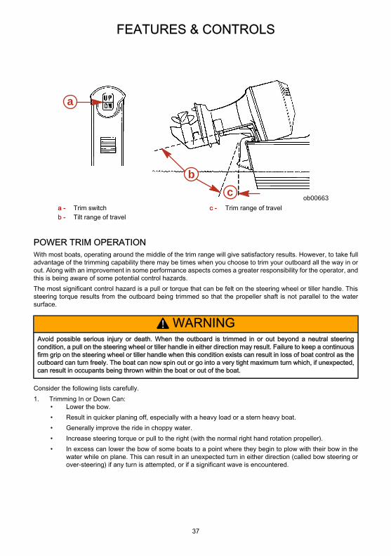
FEATURES & CONTROLS
37
ob00663
a
cb
a - Trim switchb - Tilt range of travel
c - Trim range of travel
POWER TRIM OPERATIONWith most boats, operating around the middle of the trim range will give satisfactory results. However, to take fulladvantage of the trimming capability there may be times when you choose to trim your outboard all the way in orout. Along with an improvement in some performance aspects comes a greater responsibility for the operator, andthis is being aware of some potential control hazards.The most significant control hazard is a pull or torque that can be felt on the steering wheel or tiller handle. Thissteering torque results from the outboard being trimmed so that the propeller shaft is not parallel to the watersurface.
! WARNINGAvoid possible serious injury or death. When the outboard is trimmed in or out beyond a neutral steeringcondition, a pull on the steering wheel or tiller handle in either direction may result. Failure to keep a continuousfirm grip on the steering wheel or tiller handle when this condition exists can result in loss of boat control as theoutboard can turn freely. The boat can now spin out or go into a very tight maximum turn which, if unexpected,can result in occupants being thrown within the boat or out of the boat.
Consider the following lists carefully.1. Trimming In or Down Can:
• Lower the bow.• Result in quicker planing off, especially with a heavy load or a stern heavy boat.• Generally improve the ride in choppy water.• Increase steering torque or pull to the right (with the normal right hand rotation propeller).• In excess can lower the bow of some boats to a point where they begin to plow with their bow in the
water while on plane. This can result in an unexpected turn in either direction (called bow steering orover-steering) if any turn is attempted, or if a significant wave is encountered.
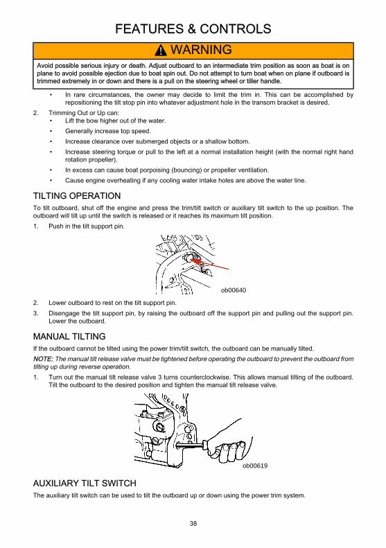
FEATURES & CONTROLS
38
! WARNINGAvoid possible serious injury or death. Adjust outboard to an intermediate trim position as soon as boat is onplane to avoid possible ejection due to boat spin out. Do not attempt to turn boat when on plane if outboard istrimmed extremely in or down and there is a pull on the steering wheel or tiller handle.
• In rare circumstances, the owner may decide to limit the trim in. This can be accomplished byrepositioning the tilt stop pin into whatever adjustment hole in the transom bracket is desired.
2. Trimming Out or Up can:• Lift the bow higher out of the water.• Generally increase top speed.• Increase clearance over submerged objects or a shallow bottom.• Increase steering torque or pull to the left at a normal installation height (with the normal right hand
rotation propeller).• In excess can cause boat porpoising (bouncing) or propeller ventilation.• Cause engine overheating if any cooling water intake holes are above the water line.
TILTING OPERATIONTo tilt outboard, shut off the engine and press the trim/tilt switch or auxiliary tilt switch to the up position. Theoutboard will tilt up until the switch is released or it reaches its maximum tilt position.1. Push in the tilt support pin.
ob00640
2. Lower outboard to rest on the tilt support pin.3. Disengage the tilt support pin, by raising the outboard off the support pin and pulling out the support pin.
Lower the outboard.
MANUAL TILTINGIf the outboard cannot be tilted using the power trim/tilt switch, the outboard can be manually tilted.NOTE: The manual tilt release valve must be tightened before operating the outboard to prevent the outboard fromtilting up during reverse operation.1. Turn out the manual tilt release valve 3 turns counterclockwise. This allows manual tilting of the outboard.
Tilt the outboard to the desired position and tighten the manual tilt release valve.
ob00619
AUXILIARY TILT SWITCHThe auxiliary tilt switch can be used to tilt the outboard up or down using the power trim system.
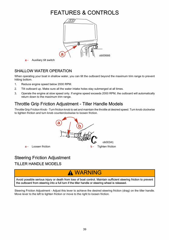
FEATURES & CONTROLS
39
a ob00666a - Auxiliary tilt switch
SHALLOW WATER OPERATIONWhen operating your boat in shallow water, you can tilt the outboard beyond the maximum trim range to preventhitting bottom.1. Reduce engine speed below 2000 RPM.2. Tilt outboard up. Make sure all the water intake holes stay submerged at all times.3. Operate the engine at slow speed only. If engine speed exceeds 2000 RPM, the outboard will automatically
return down to the maximum trim range.
Throttle Grip Friction Adjustment - Tiller Handle ModelsThrottle Grip Friction Knob - Turn friction knob to set and maintain the throttle at desired speed. Turn knob clockwiseto tighten friction and turn knob counterclockwise to loosen friction.
a b
ob00341a - Loosen friction b - Tighten friction
Steering Friction AdjustmentTILLER HANDLE MODELS
! WARNINGAvoid possible serious injury or death from loss of boat control. Maintain sufficient steering friction to preventthe outboard from steering into a full turn if the tiller handle or steering wheel is released.
Steering Friction Adjustment - Adjust this lever to achieve the desired steering friction (drag) on the tiller handle.Move lever to the left to tighten friction or move to the right to loosen friction.
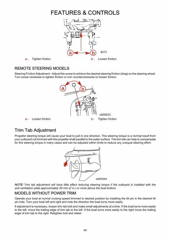
FEATURES & CONTROLS
40
3073a ba - Tighten friction b - Loosen friction
REMOTE STEERING MODELSSteering Friction Adjustment - Adjust this screw to achieve the desired steering friction (drag) on the steering wheel.Turn screw clockwise to tighten friction or turn counterclockwise to loosen friction.
ob00623
a b
a - Loosen friction b - Tighten friction
Trim Tab AdjustmentPropeller steering torque will cause your boat to pull in one direction. This steering torque is a normal result fromyour outboard not trimmed with the propeller shaft parallel to the water surface. The trim tab can help to compensatefor this steering torque in many cases and can be adjusted within limits to reduce any unequal steering effort.
ob00344
NOTE: Trim tab adjustment will have little effect reducing steering torque if the outboard is installed with theanti-ventilation plate approximately 50 mm (2 in.) or more above the boat bottom.
MODELS WITHOUT POWER TRIMOperate your boat at normal cruising speed trimmed to desired position by installing the tilt pin in the desired tiltpin hole. Turn your boat left and right and note the direction the boat turns more easily.If adjustment is necessary, loosen trim tab bolt and make small adjustments at a time. If the boat turns more easilyto the left, move the trailing edge of trim tab to the left. If the boat turns more easily to the right move the trailingedge of trim tab to the right. Retighten bolt and retest.

FEATURES & CONTROLS
41
MODELS WITH POWER TRIMOperate your boat at normal cruising speed, trimmed to desired position. Turn your boat left and right and note thedirection the boat turns more easily.If adjustment is necessary, loosen trim tab bolt and make small adjustments at a time. If the boat turns more easilyto the left, move the trailing edge of trim tab to the left. If the boat turns more easily to the right move the trailingedge of trim tab to the right. Retighten bolt and retest.
OPERATION
42
Pre-Starting Check List• Operator knows safe navigation, boating, and operating procedures.• An approved personal flotation device of suitable size for each person aboard and readily accessible (it is
the law).• A ring type life buoy or buoyant cushion designed to be thrown to a person in the water.• Know the boats maximum load capacity. Look at the boat capacity plate.• Fuel supply OK.• Oil supply (oil injection) OK.• Arrange passengers and load in the boat so the weight is distributed evenly and everyone is seated in a
proper seat.• Tell someone where you are going and when you expect to return.• It is illegal to operate a boat while under the influence of alcohol or drugs.• Know the waters and area you will be boating; tides, currents, sand bars, rocks, and other hazards.• Make inspection checks listed in Maintenance - Inspection and Maintenance Schedule.
Operating In Freezing TemperaturesWhen using your outboard or having your outboard moored in freezing or near freezing temperatures, keep theoutboard tilted down at all times so the gearcase is submerged. This prevents trapped water in gearcase fromfreezing and causing possible damage to the water pump and other components.If there is a chance of ice forming on the water, the outboard should be removed and drained completely of water.If ice should form at the water level inside the outboard driveshaft housing, it will block water flow to the enginecausing possible damage.
Operating In Salt Water Or Polluted WaterWe recommend that you flush the internal water passages of your outboard with fresh water after each use in saltor polluted water. This will prevent a buildup of deposits from clogging the water passages. Refer to Maintenance- Flushing The Cooling System.If you keep your boat moored in the water, always tilt the outboard so the gearcase is completely out of water(except in freezing temperatures) when not in use.Wash the outboard exterior and flush out the exhaust outlet of the propeller and gearcase with fresh water aftereach use. Each month, spray Mercury Precision or Quicksilver Corrosion Guard on external metal surfaces. Donot spray on corrosion control anodes as this will reduce the effectiveness of the anodes.
Operating at High ElevationsIMPORTANT: To prevent serious damage to the engine caused by a lean fuel mixture, do not operate youroutboard (if the jets were changed for high elevation) at a lower elevation unless the jets are changed again tocorrespond to the new elevation.Operating your outboard at an elevation higher than 750 m (2500 ft.) above sea level may require a carburetor jetchange and/or different pitch propeller. Consult your dealer. This will reduce the normal performance lossexperienced as a result of reduced oxygen in the air causing an overly rich fuel mixture.
Engine Break-in Procedure
! CAUTIONSevere damage to the engine can result by not complying with the Engine Break-in Procedure.
MODELS WITH OIL INJECTIONEngine Break-in Fuel Mixture - Use a 50:1 (2%) gasoline/oil mixture in the first tank of fuel. Use of this fuel mixturecombined with oil from the oil injection system will supply adequate lubrication during engine break-in.
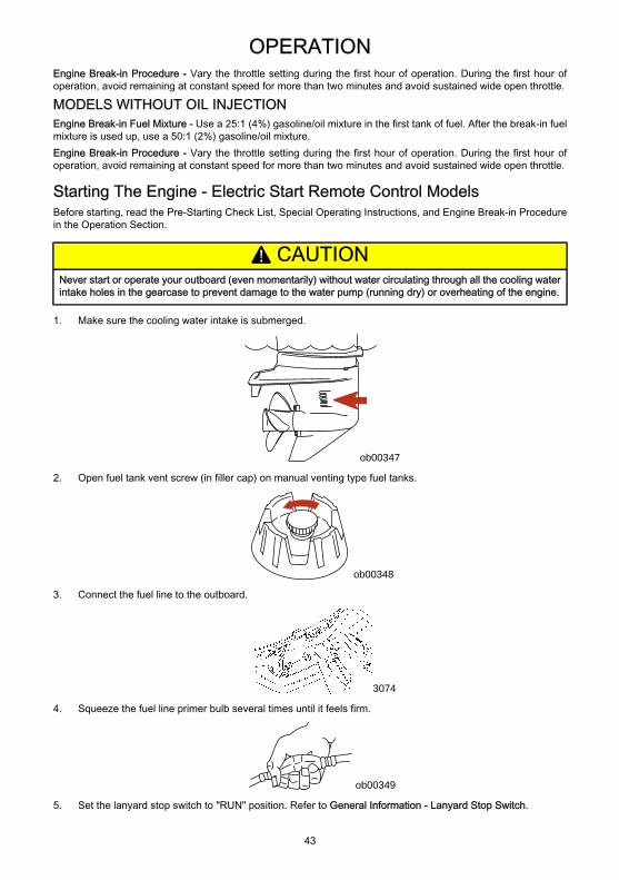
OPERATION
43
Engine Break-in Procedure - Vary the throttle setting during the first hour of operation. During the first hour ofoperation, avoid remaining at constant speed for more than two minutes and avoid sustained wide open throttle.
MODELS WITHOUT OIL INJECTIONEngine Break-in Fuel Mixture - Use a 25:1 (4%) gasoline/oil mixture in the first tank of fuel. After the break-in fuelmixture is used up, use a 50:1 (2%) gasoline/oil mixture.Engine Break-in Procedure - Vary the throttle setting during the first hour of operation. During the first hour ofoperation, avoid remaining at constant speed for more than two minutes and avoid sustained wide open throttle.
Starting The Engine - Electric Start Remote Control ModelsBefore starting, read the Pre-Starting Check List, Special Operating Instructions, and Engine Break-in Procedurein the Operation Section.
! CAUTIONNever start or operate your outboard (even momentarily) without water circulating through all the cooling waterintake holes in the gearcase to prevent damage to the water pump (running dry) or overheating of the engine.
1. Make sure the cooling water intake is submerged.
ob00347
2. Open fuel tank vent screw (in filler cap) on manual venting type fuel tanks.
ob00348
3. Connect the fuel line to the outboard.
3074
4. Squeeze the fuel line primer bulb several times until it feels firm.
ob00349
5. Set the lanyard stop switch to "RUN" position. Refer to General Information - Lanyard Stop Switch.
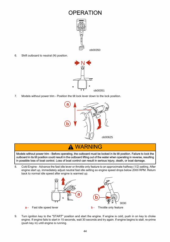
OPERATION
44
ob00350
6. Shift outboard to neutral (N) position.
N
ob00351
7. Models without power trim - Position the tilt lock lever down to the lock position.
ob00625
a
b
! WARNINGModels without power trim - Before operating, the outboard must be locked in its tilt position. Failure to lock theoutboard in its tilt position could result in the outboard lifting out of the water when operating in reverse, resultingin possible loss of boat control. Loss of boat control can result in serious injury, death, or boat damage.
8. Cold Engine - Advance the fast idle lever or throttle only feature to an approximate halfway (1/2) setting. Afterengine start up, immediately adjust neutral fast idle setting so engine speed drops below 2000 RPM. Returnback to normal idle speed after engine is warmed up.
3030
a b
a - Fast idle speed lever b - Throttle only feature
9. Turn ignition key to the "START" position and start the engine. If engine is cold, push in on key to chokeengine. If engine fails to start in 10 seconds, wait 30 seconds and try again. If engine begins to stall, re-prime(push key in) until engine is running.
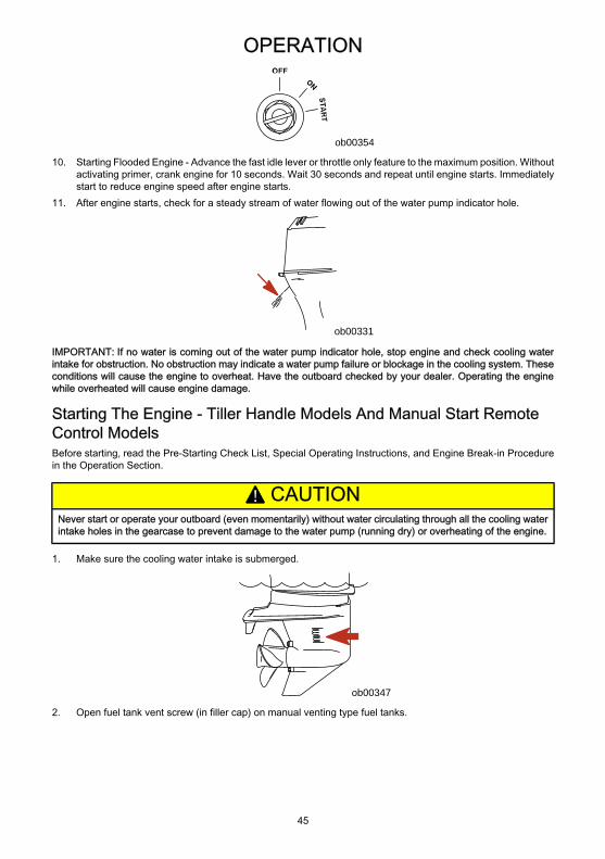
OPERATION
45
ob00354
10. Starting Flooded Engine - Advance the fast idle lever or throttle only feature to the maximum position. Withoutactivating primer, crank engine for 10 seconds. Wait 30 seconds and repeat until engine starts. Immediatelystart to reduce engine speed after engine starts.
11. After engine starts, check for a steady stream of water flowing out of the water pump indicator hole.
ob00331
IMPORTANT: If no water is coming out of the water pump indicator hole, stop engine and check cooling waterintake for obstruction. No obstruction may indicate a water pump failure or blockage in the cooling system. Theseconditions will cause the engine to overheat. Have the outboard checked by your dealer. Operating the enginewhile overheated will cause engine damage.
Starting The Engine - Tiller Handle Models And Manual Start RemoteControl ModelsBefore starting, read the Pre-Starting Check List, Special Operating Instructions, and Engine Break-in Procedurein the Operation Section.
! CAUTIONNever start or operate your outboard (even momentarily) without water circulating through all the cooling waterintake holes in the gearcase to prevent damage to the water pump (running dry) or overheating of the engine.
1. Make sure the cooling water intake is submerged.
ob00347
2. Open fuel tank vent screw (in filler cap) on manual venting type fuel tanks.
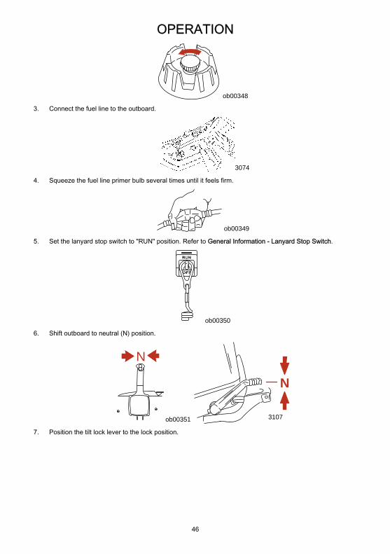
OPERATION
46
ob00348
3. Connect the fuel line to the outboard.
3074
4. Squeeze the fuel line primer bulb several times until it feels firm.
ob00349
5. Set the lanyard stop switch to "RUN" position. Refer to General Information - Lanyard Stop Switch.
ob00350
6. Shift outboard to neutral (N) position.
N
ob00351
NN
3107
7. Position the tilt lock lever to the lock position.
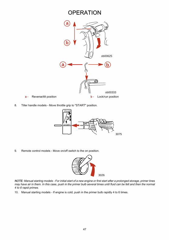
OPERATION
47
ob00625
a
b
a b
ob00333a - Reverse/tilt position b - Lock/run position
8. Tiller handle models - Move throttle grip to "START" position.
0%100
STARTSTART
3075
9. Remote control models - Move on/off switch to the on position.
3026
NOTE: Manual starting models - For initial start of a new engine or first start after a prolonged storage, primer linesmay have air in them. In this case, push in the primer bulb several times until fluid can be felt and then the normal4 to 6 rapid primes.10. Manual starting models - If engine is cold, push in the primer bulb rapidly 4 to 6 times.
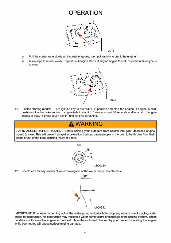
OPERATION
48
3076
a. Pull the starter rope slowly until starter engages, then pull rapidly to crank the engine.b. Allow rope to return slowly. Repeat until engine starts. If engine begins to stall, re-prime until engine is
running.
3072
11. Electric starting models - Turn ignition key to the "START" position and start the engine. If engine is cold,push in on key to choke engine. If engine fails to start in 10 seconds, wait 30 seconds and try again. If enginebegins to stall, re-prime (push key in) until engine is running.
! WARNINGRAPID ACCELERATION HAZARD - Before shifting your outboard from neutral into gear, decrease enginespeed to slow. This will prevent a rapid acceleration that can cause people in the boat to be thrown from theirseats or out of the boat, causing injury or death.
ob00354
12. Check for a steady stream of water flowing out of the water pump indicator hole.
ob00331
IMPORTANT: If no water is coming out of the water pump indicator hole, stop engine and check cooling waterintake for obstruction. No obstruction may indicate a water pump failure or blockage in the cooling system. Theseconditions will cause the engine to overheat. Have the outboard checked by your dealer. Operating the enginewhile overheated will cause serious engine damage.
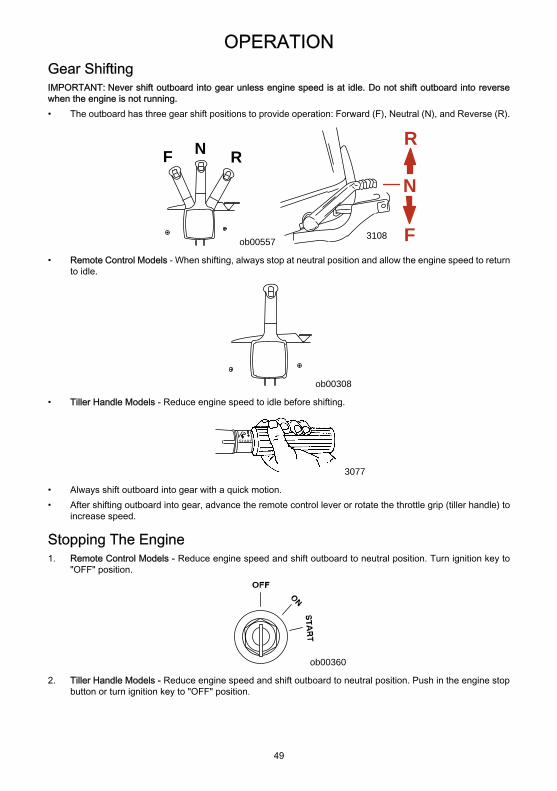
OPERATION
49
Gear ShiftingIMPORTANT: Never shift outboard into gear unless engine speed is at idle. Do not shift outboard into reversewhen the engine is not running.• The outboard has three gear shift positions to provide operation: Forward (F), Neutral (N), and Reverse (R).
N RF
ob00557
NN
3108 F
R
• Remote Control Models - When shifting, always stop at neutral position and allow the engine speed to returnto idle.
ob00308
• Tiller Handle Models - Reduce engine speed to idle before shifting.
START
3077
• Always shift outboard into gear with a quick motion.• After shifting outboard into gear, advance the remote control lever or rotate the throttle grip (tiller handle) to
increase speed.
Stopping The Engine1. Remote Control Models - Reduce engine speed and shift outboard to neutral position. Turn ignition key to
"OFF" position.
ob00360
2. Tiller Handle Models - Reduce engine speed and shift outboard to neutral position. Push in the engine stopbutton or turn ignition key to "OFF" position.
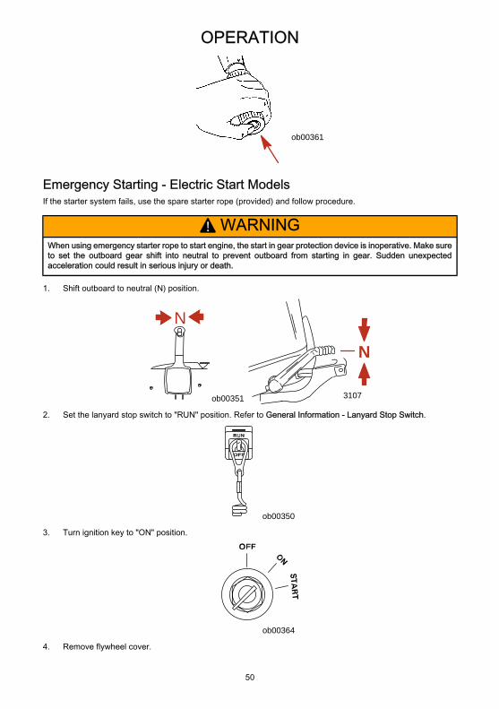
OPERATION
50
ob00361
Emergency Starting - Electric Start ModelsIf the starter system fails, use the spare starter rope (provided) and follow procedure.
! WARNINGWhen using emergency starter rope to start engine, the start in gear protection device is inoperative. Make sureto set the outboard gear shift into neutral to prevent outboard from starting in gear. Sudden unexpectedacceleration could result in serious injury or death.
1. Shift outboard to neutral (N) position.
N
ob00351
NN
3107
2. Set the lanyard stop switch to "RUN" position. Refer to General Information - Lanyard Stop Switch.
ob00350
3. Turn ignition key to "ON" position.
ob00364
4. Remove flywheel cover.
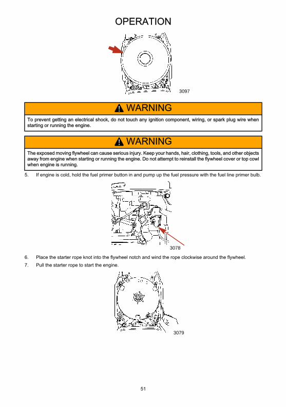
OPERATION
51
3097
! WARNINGTo prevent getting an electrical shock, do not touch any ignition component, wiring, or spark plug wire whenstarting or running the engine.
! WARNINGThe exposed moving flywheel can cause serious injury. Keep your hands, hair, clothing, tools, and other objectsaway from engine when starting or running the engine. Do not attempt to reinstall the flywheel cover or top cowlwhen engine is running.
5. If engine is cold, hold the fuel primer button in and pump up the fuel pressure with the fuel line primer bulb.
3078
6. Place the starter rope knot into the flywheel notch and wind the rope clockwise around the flywheel.7. Pull the starter rope to start the engine.
3079
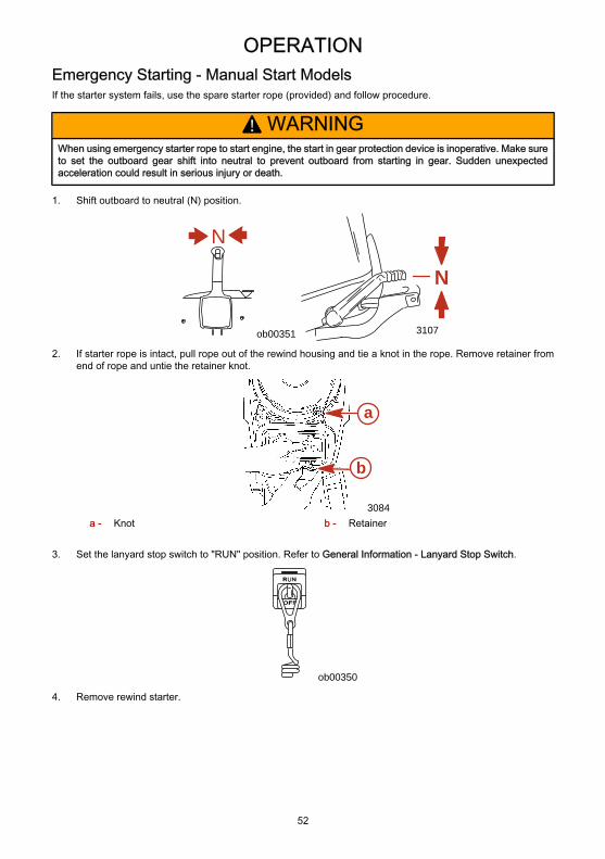
OPERATION
52
Emergency Starting - Manual Start ModelsIf the starter system fails, use the spare starter rope (provided) and follow procedure.
! WARNINGWhen using emergency starter rope to start engine, the start in gear protection device is inoperative. Make sureto set the outboard gear shift into neutral to prevent outboard from starting in gear. Sudden unexpectedacceleration could result in serious injury or death.
1. Shift outboard to neutral (N) position.
N
ob00351
NN
3107
2. If starter rope is intact, pull rope out of the rewind housing and tie a knot in the rope. Remove retainer fromend of rope and untie the retainer knot.
3084
a
b
a - Knot b - Retainer
3. Set the lanyard stop switch to "RUN" position. Refer to General Information - Lanyard Stop Switch.
ob00350
4. Remove rewind starter.
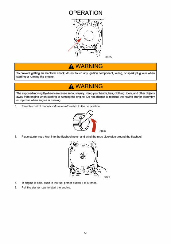
OPERATION
53
3085
! WARNINGTo prevent getting an electrical shock, do not touch any ignition component, wiring, or spark plug wire whenstarting or running the engine.
! WARNINGThe exposed moving flywheel can cause serious injury. Keep your hands, hair, clothing, tools, and other objectsaway from engine when starting or running the engine. Do not attempt to reinstall the rewind starter assemblyor top cowl when engine is running.
5. Remote control models - Move on/off switch to the on position.
3026
6. Place starter rope knot into the flywheel notch and wind the rope clockwise around the flywheel.
3079
7. In engine is cold, push in the fuel primer button 4 to 6 times.8. Pull the starter rope to start the engine.

MAINTENANCE
54
Outboard CareTo keep your outboard in the best operating condition, it is important that your outboard receive the periodicinspections and maintenance listed in the Inspection and Maintenance Schedule. We urge you to keep itmaintained properly to ensure the safety of you and your passengers, and retain its dependability.
! WARNINGNeglected inspection and maintenance service of your outboard or attempting to perform maintenance or repairon your outboard if you are not familiar with the correct service and safety procedures could cause personalinjury, death, or product failure.
Record maintenance performed in Maintenance Log at the back of this book. Save all maintenance work ordersand receipts.
SELECTING REPLACEMENT PARTS FOR YOUR OUTBOARDWe recommend using original Mercury Precision or Quicksilver replacement parts and Genuine Lubricants.
! WARNINGUsing a replacement part that is inferior to the original part could result in personal injury, death, or productfailure.
EPA EmissionsEMISSION CERTIFICATION LABELAn emission certification label, showing emission levels and engine specifications directly related to emissions, isplaced on the engine at time of manufacture.
EMISSION CONTROLINFORMATION
TIMING (IN DEGREES):
FAMILY:FEL:cc
IDLE SPEED:hp
GAP :
g/kW h
Standard spark plug:Suppressor spark plug:
This engine conforms to model year EPA regulations for Marine SI engines.Refer to Owner's Manual for required maintenance.
Valve Clearance (Cold) mm IntakeExhaust
ab
c
de
fg
hi
ob01071a - Idle speedb - Engine horsepowerc - Timing specificationd - Recommended spark plug and gape - Valve clearance (if applicable)
f - Family numberg - Maximum emission output for the engine
familyh - Piston placementi - Date of manufacture
OWNER RESPONSIBILITYThe owner/operator is required to have routine engine maintenance performed to maintain emission levels withinprescribed certification standards.The owner/operator is not to modify the engine in any manner that would alter the horsepower or allow emissionslevels to exceed their predetermined factory specifications.
MAINTENANCE
55
Inspection And Maintenance ScheduleBEFORE EACH USE• Check that lanyard stop switch stops the engine.• Visually inspect the fuel system for deterioration or leaks.• Check outboard for tightness on transom.• Check steering system for binding or loose components.• Remote control models - Visually check steering link rod fasteners for proper tightness. See Steering Link
Rod Fasteners.• Check propeller blades for damage.
AFTER EACH USE• Flush out the outboard cooling system if operating in salt or polluted water. See Flushing the Cooling System.• Wash off all salt deposits and flush out the exhaust outlet of the propeller and gearcase with fresh water if
operating in salt water.
EVERY 100 HOURS OF USE OR ONCE YEARLY, WHICHEVER OCCURS FIRST• Lubricate all lubrication points. Lubricate more frequently when used in salt water. See Lubrication Points.• Inspect and clean spark plugs. See Spark Plug Inspection and Replacement.• Check engine fuel filter for contaminants. See Fuel System.• Adjust carburators. (If required)1.
• Check engine timing setup.1.
• Check corrosion control anodes. Check more frequently when used in salt water. See Corrosion ControlAnodes.
• Drain and replace gearcase lubricant. See Gearcase Lubrication.• Lubricate splines on the driveshaft.1.
• Check power trim fluid. See Checking Power Trim Fluid.• Inspect battery. See Battery Inspection.• Check control cable adjustments.1.
• Remove engine deposits with Mercury Precision or Quicksilver Power Tune Engine Cleaner.• Check tightness of bolts, nuts, and other fasteners.
EVERY 300 HOURS OF USE OR THREE YEARS• Replace water pump impeller (more often if overheating occurs or reduced water pressure is noted).1.
BEFORE PERIODS OF STORAGE• Refer to Storage procedure. See Storage section.
Flushing The Cooling SystemFlush the internal water passages of the outboard with fresh water after each use in salt, polluted, or muddy water.This will help prevent a buildup of deposits from clogging the internal water passages.Use a Mercury Precision or Quicksilver accessory (or equivalent) flushing attachment.
! WARNINGTo avoid possible injury when flushing, remove the propeller. Refer to Propeller Replacement, following.
1. Remove propeller. Refer to Propeller Replacement. Install the flushing attachment so the rubber cups fittightly over the cooling water intake.
1. These items should be serviced by an authorized dealer.
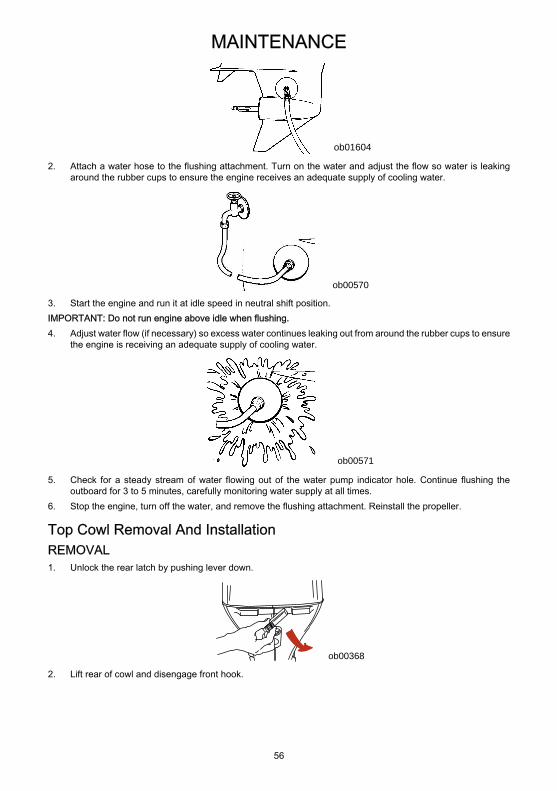
MAINTENANCE
56
ob01604
2. Attach a water hose to the flushing attachment. Turn on the water and adjust the flow so water is leakingaround the rubber cups to ensure the engine receives an adequate supply of cooling water.
ob00570
3. Start the engine and run it at idle speed in neutral shift position.IMPORTANT: Do not run engine above idle when flushing.4. Adjust water flow (if necessary) so excess water continues leaking out from around the rubber cups to ensure
the engine is receiving an adequate supply of cooling water.
ob00571
5. Check for a steady stream of water flowing out of the water pump indicator hole. Continue flushing theoutboard for 3 to 5 minutes, carefully monitoring water supply at all times.
6. Stop the engine, turn off the water, and remove the flushing attachment. Reinstall the propeller.
Top Cowl Removal And InstallationREMOVAL1. Unlock the rear latch by pushing lever down.
ob00368
2. Lift rear of cowl and disengage front hook.
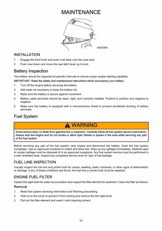
MAINTENANCE
57
ob00369
INSTALLATION1. Engage the front hook and push cowl back over the cowl seal.2. Push cowl down and move the rear latch lever up to lock.
Battery InspectionThe battery should be inspected at periodic intervals to ensure proper engine starting capability.IMPORTANT: Read the safety and maintenance instructions which accompany your battery.1. Turn off the engine before servicing the battery.2. Add water as necessary to keep the battery full.3. Make sure the battery is secure against movement.4. Battery cable terminals should be clean, tight, and correctly installed. Positive to positive and negative to
negative.5. Make sure the battery is equipped with a nonconductive shield to prevent accidental shorting of battery
terminals.
Fuel System
! WARNINGAvoid serious injury or death from gasoline fire or explosion. Carefully follow all fuel system service instructions.Always stop the engine and do not smoke or allow open flames or sparks in the area while servicing any partof the fuel system.
Before servicing any part of the fuel system, stop engine and disconnect the battery. Drain the fuel systemcompletely. Use an approved container to collect and store fuel. Wipe up any spillage immediately. Material usedto contain spillage must be disposed of in an approved receptacle. Any fuel system service must be performed ina well ventilated area. Inspect any completed service work for sign of fuel leakage.
FUEL LINE INSPECTIONVisually inspect the fuel line and primer bulb for cracks, swelling, leaks, hardness, or other signs of deteriorationor damage. If any of these conditions are found, the fuel line or primer bulb must be replaced.
ENGINE FUEL FILTERInspect the sight bowl for water accumulation and inspect the filter element for sediment. Clean the filter as follows.
Removal1. Read fuel system servicing information and Warning preceeding.2. Hold on to the cover to prevent it from turning and remove the the sight bowl.3. Pull out the filter element and wash it with cleaning solvent.
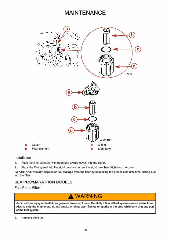
MAINTENANCE
58
3933
b
c
d
a
ob01406
a
b
c
d
a - Coverb - Filter element
c - O-ringd - Sight bowl
Installation1. Push the filter element (with open end toward cover) into the cover.2. Place the O-ring seal into the sight bowl and screw the sight bowl hand tight into the cover.IMPORTANT: Visually inspect for fuel leakage from the filter by squeezing the primer bulb until firm, forcing fuelinto the filter.
SEA PRO/MARATHON MODELSFuel Pump Filter
! WARNINGAvoid serious injury or death from gasoline fire or explosion. Carefully follow all fuel system service instructions.Always stop the engine and do not smoke or allow open flames or sparks in the area while servicing any partof the fuel system.
1. Remove the filter.
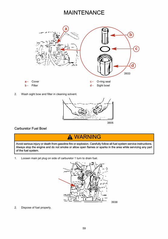
MAINTENANCE
59
3933
b
c
d
a
a - Coverb - Filter
c - O-ring seald - Sight bowl
2. Wash sight bow and filter in cleaning solvent.
3806
Carburetor Fuel Bowl
! WARNINGAvoid serious injury or death from gasoline fire or explosion. Carefully follow all fuel system service instructions.Always stop the engine and do not smoke or allow open flames or sparks in the area while servicing any partof the fuel system.
1. Loosen main jet plug on side of carburetor 1 turn to drain fuel.
3938
2. Dispose of fuel properly.

MAINTENANCE
60
CARBURETOR ADJUSTMENTSSlow Speed Mixture Adjustment1. Before starting engine, turn the slow speed mixture screw in until it is lightly seated then back it out 1-1/4 turns.
3951
2. With boat tied securely to dock, start engine and allow it to warm up.3. Shift the outboard into forward gear while maintaining idle speed.
NN
3108 F
R 0%100
STARTSTART
3075
4. Turn the slow speed mixture screw slowly in until the engine starts to misfire or stall due to a lean mixture.Note the position of the screw slot.
5. Turn the slow speed mixture screw slowly out until the engine starts to load up or fire unevenly due to a richmixture. Note the position of the screw slot.
6. Set the slow speed mixture screw midway between the rich and lean setting. When in doubt, set the mixtureslightly rich rather than too lean.
Engine Idle Speed Adjustment1. With boat tied securely to dock, start engine and allow it to warm up.2. Shift the outboard into forward gear while maintaining idle speed.
NN
3108 F
R 0%100
STARTSTART
3075
3. Adjust the idle speed screw to obtain the recommended engine idle speed. Refer to General Information -Specifications.
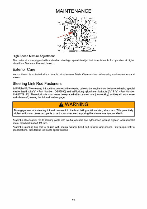
MAINTENANCE
61
High Speed Mixture AdjustmentThe carburetor is equipped with a standard size high speed fixed jet that is replaceable for operation at higherelevations. See an authorized dealer.
Exterior CareYour outboard is protected with a durable baked enamel finish. Clean and wax often using marine cleaners andwaxes.
Steering Link Rod FastenersIMPORTANT: The steering link rod that connects the steering cable to the engine must be fastened using specialwasher head bolt ("a" - Part Number 10-856680) and self-locking nylon insert locknuts ("b" & "e" - Part Number11-826709113). These locknuts must never be replaced with common nuts (non-locking) as they will work looseand vibrate off, freeing the link rod to disengage.
! WARNINGDisengagement of a steering link rod can result in the boat taking a full, sudden, sharp turn. This potentiallyviolent action can cause occupants to be thrown overboard exposing them to serious injury or death.
Assemble steering link rod to steering cable with two flat washers and nylon insert locknut. Tighten locknut until itseats, then back nut off 1/4 turn.Assemble steering link rod to engine with special washer head bolt, locknut and spacer. First torque bolt tospecifications, then torque locknut to specifications.
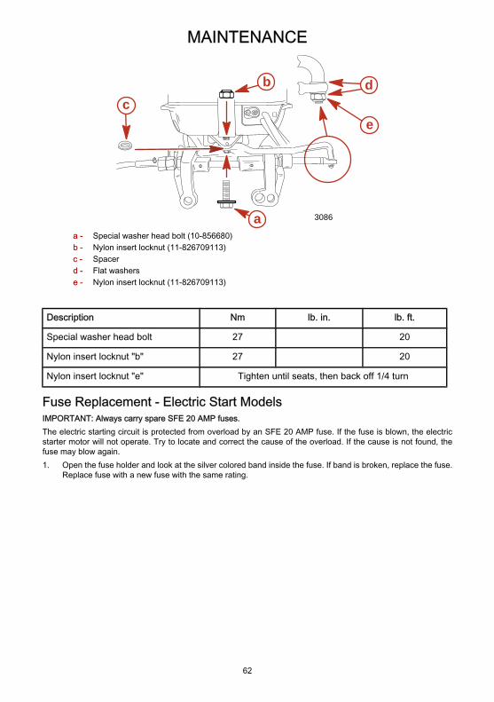
MAINTENANCE
62
3086a
bc
e
d
a - Special washer head bolt (10-856680)b - Nylon insert locknut (11-826709113)c - Spacerd - Flat washerse - Nylon insert locknut (11-826709113)
Description Nm lb. in. lb. ft.
Special washer head bolt 27 20
Nylon insert locknut "b" 27 20
Nylon insert locknut "e" Tighten until seats, then back off 1/4 turn
Fuse Replacement - Electric Start ModelsIMPORTANT: Always carry spare SFE 20 AMP fuses.The electric starting circuit is protected from overload by an SFE 20 AMP fuse. If the fuse is blown, the electricstarter motor will not operate. Try to locate and correct the cause of the overload. If the cause is not found, thefuse may blow again.1. Open the fuse holder and look at the silver colored band inside the fuse. If band is broken, replace the fuse.
Replace fuse with a new fuse with the same rating.

MAINTENANCE
63
3087
ba c
a - Good bandb - Broken band
c - Fuse holder
Corrosion Control AnodeThe outboard has corrosion control anodes at different locations. An anode helps protect the outboard againstgalvanic corrosion by sacrificing its metal to be slowly eroded instead of the outboard metals.Each anode requires periodic inspection, especially in salt water which will accelerate the erosion. To maintainthis corrosion protection, always replace the anode before it is completely eroded. Never paint or apply a protectivecoating on the anode as this will reduce effectiveness of the anode.The trim tab on the gearcase is a corrosion control anode. Models that have a longer transom bracket will haveanother anode installed on the bottom of the transom bracket assembly.
3088
a
ba - Trim tab anode b - Transom bracket anode
Propeller Replacement
! WARNINGIf the propeller shaft is rotated while the engine is in gear, there is the possibility that the engine will crank overand start. To prevent this type of accidental engine starting and possible serious injury caused from being struckby a rotating propeller, always shift outboard to neutral position and remove spark plug leads when you areservicing the propeller.
1. Shift outboard to neutral (N) position.
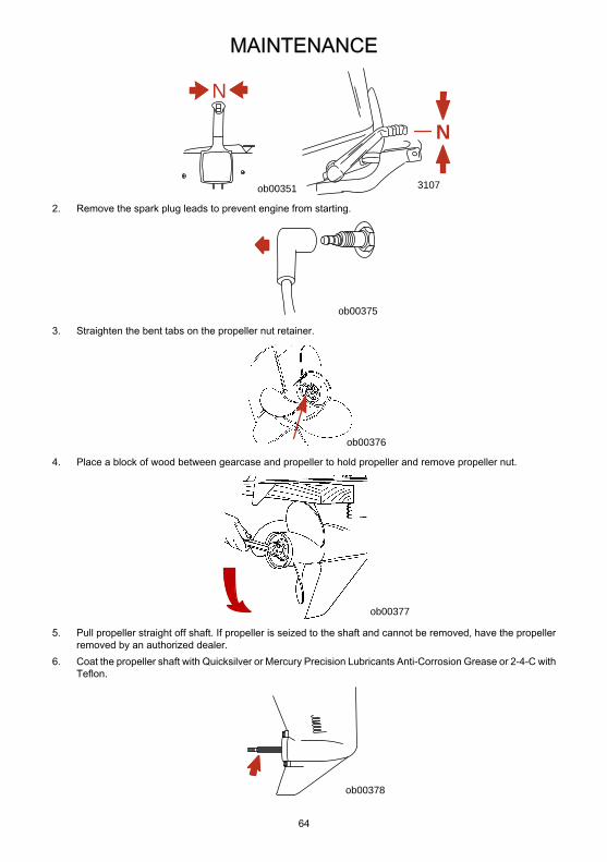
MAINTENANCE
64
N
ob00351
NN
3107
2. Remove the spark plug leads to prevent engine from starting.
ob00375
3. Straighten the bent tabs on the propeller nut retainer.
ob00376
4. Place a block of wood between gearcase and propeller to hold propeller and remove propeller nut.
ob00377
5. Pull propeller straight off shaft. If propeller is seized to the shaft and cannot be removed, have the propellerremoved by an authorized dealer.
6. Coat the propeller shaft with Quicksilver or Mercury Precision Lubricants Anti-Corrosion Grease or 2-4-C withTeflon.
ob00378
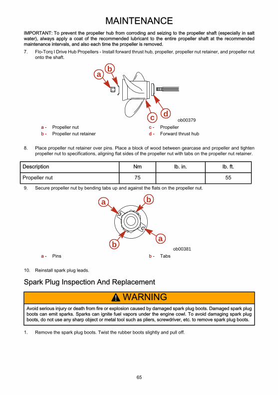
MAINTENANCE
65
IMPORTANT: To prevent the propeller hub from corroding and seizing to the propeller shaft (especially in saltwater), always apply a coat of the recommended lubricant to the entire propeller shaft at the recommendedmaintenance intervals, and also each time the propeller is removed.7. Flo-Torq I Drive Hub Propellers - Install forward thrust hub, propeller, propeller nut retainer, and propeller nut
onto the shaft.
ob00379
a b
c da - Propeller nutb - Propeller nut retainer
c - Propellerd - Forward thrust hub
8. Place propeller nut retainer over pins. Place a block of wood between gearcase and propeller and tightenpropeller nut to specifications, aligning flat sides of the propeller nut with tabs on the propeller nut retainer.
Description Nm lb. in. lb. ft.
Propeller nut 75 55
9. Secure propeller nut by bending tabs up and against the flats on the propeller nut.
ob00381b
a
ba
a - Pins b - Tabs
10. Reinstall spark plug leads.
Spark Plug Inspection And Replacement
! WARNINGAvoid serious injury or death from fire or explosion caused by damaged spark plug boots. Damaged spark plugboots can emit sparks. Sparks can ignite fuel vapors under the engine cowl. To avoid damaging spark plugboots, do not use any sharp object or metal tool such as pliers, screwdriver, etc. to remove spark plug boots.
1. Remove the spark plug boots. Twist the rubber boots slightly and pull off.
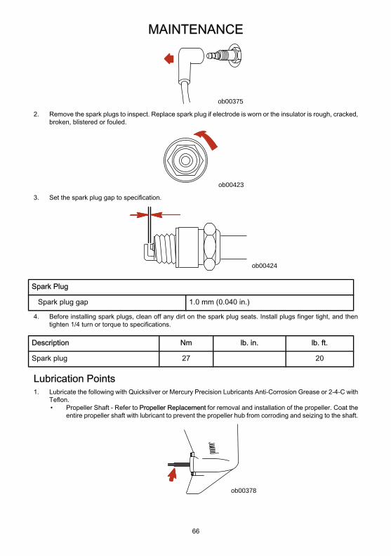
MAINTENANCE
66
ob00375
2. Remove the spark plugs to inspect. Replace spark plug if electrode is worn or the insulator is rough, cracked,broken, blistered or fouled.
ob00423
3. Set the spark plug gap to specification.
ob00424
Spark Plug
Spark plug gap 1.0 mm (0.040 in.)
4. Before installing spark plugs, clean off any dirt on the spark plug seats. Install plugs finger tight, and thentighten 1/4 turn or torque to specifications.
Description Nm lb. in. lb. ft.
Spark plug 27 20
Lubrication Points1. Lubricate the following with Quicksilver or Mercury Precision Lubricants Anti-Corrosion Grease or 2-4-C with
Teflon.• Propeller Shaft - Refer to Propeller Replacement for removal and installation of the propeller. Coat the
entire propeller shaft with lubricant to prevent the propeller hub from corroding and seizing to the shaft.
ob00378
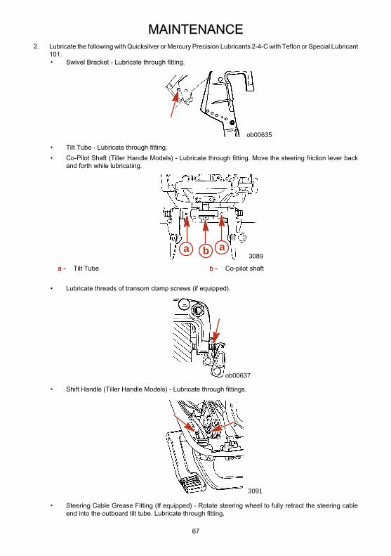
MAINTENANCE
67
2. Lubricate the following with Quicksilver or Mercury Precision Lubricants 2-4-C with Teflon or Special Lubricant101.• Swivel Bracket - Lubricate through fitting.
ob00635
• Tilt Tube - Lubricate through fitting.• Co-Pilot Shaft (Tiller Handle Models) - Lubricate through fitting. Move the steering friction lever back
and forth while lubricating.
3089aba
a - Tilt Tube b - Co-pilot shaft
• Lubricate threads of transom clamp screws (if equipped).
ob00637
• Shift Handle (Tiller Handle Models) - Lubricate through fittings.
3091
• Steering Cable Grease Fitting (If equipped) - Rotate steering wheel to fully retract the steering cableend into the outboard tilt tube. Lubricate through fitting.
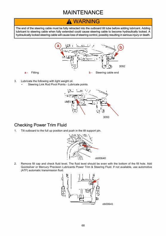
MAINTENANCE
68
! WARNINGThe end of the steering cable must be fully retracted into the outboard tilt tube before adding lubricant. Addinglubricant to steering cable when fully extended could cause steering cable to become hydraulically locked. Ahydraulically locked steering cable will cause loss of steering control, possibly resulting in serious injury or death.
3092
a b
a - Fitting b - Steering cable end
3. Lubricate the following with light weight oil.• Steering Link Rod Pivot Points - Lubricate points.
3093
Checking Power Trim Fluid1. Tilt outboard to the full up position and push in the tilt support pin.
ob00640
2. Remove fill cap and check fluid level. The fluid level should be even with the bottom of the fill hole. AddQuicksilver or Mercury Precision Lubricants Power Trim & Steering Fluid. If not available, use automotive(ATF) automatic transmission fluid.
ob00641
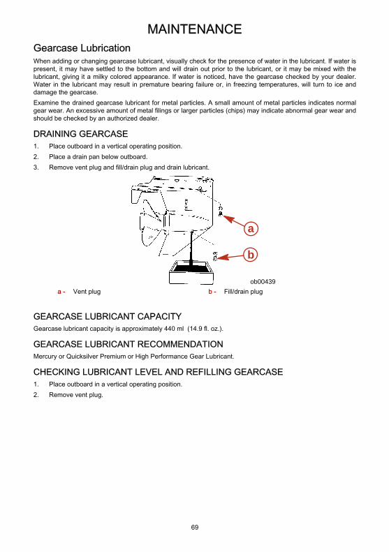
MAINTENANCE
69
Gearcase LubricationWhen adding or changing gearcase lubricant, visually check for the presence of water in the lubricant. If water ispresent, it may have settled to the bottom and will drain out prior to the lubricant, or it may be mixed with thelubricant, giving it a milky colored appearance. If water is noticed, have the gearcase checked by your dealer.Water in the lubricant may result in premature bearing failure or, in freezing temperatures, will turn to ice anddamage the gearcase.Examine the drained gearcase lubricant for metal particles. A small amount of metal particles indicates normalgear wear. An excessive amount of metal filings or larger particles (chips) may indicate abnormal gear wear andshould be checked by an authorized dealer.
DRAINING GEARCASE1. Place outboard in a vertical operating position.2. Place a drain pan below outboard.3. Remove vent plug and fill/drain plug and drain lubricant.
a
b
ob00439a - Vent plug b - Fill/drain plug
GEARCASE LUBRICANT CAPACITYGearcase lubricant capacity is approximately 440 ml (14.9 fl. oz.).
GEARCASE LUBRICANT RECOMMENDATIONMercury or Quicksilver Premium or High Performance Gear Lubricant.
CHECKING LUBRICANT LEVEL AND REFILLING GEARCASE1. Place outboard in a vertical operating position.2. Remove vent plug.
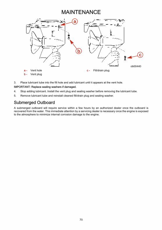
MAINTENANCE
70
ob00440
a
cb
a - Vent holeb - Vent plug
c - Fill/drain plug
3. Place lubricant tube into the fill hole and add lubricant until it appears at the vent hole.IMPORTANT: Replace sealing washers if damaged.4. Stop adding lubricant. Install the vent plug and sealing washer before removing the lubricant tube.5. Remove lubricant tube and reinstall cleaned fill/drain plug and sealing washer.
Submerged OutboardA submerged outboard will require service within a few hours by an authorized dealer once the outboard isrecovered from the water. This immediate attention by a servicing dealer is necessary once the engine is exposedto the atmosphere to minimize internal corrosion damage to the engine.
STORAGE
71
Storage PreparationThe major consideration in preparing your outboard for storage is to protect it from rust, corrosion, and damagecaused by freezing of trapped water.The following storage procedures should be followed to prepare your outboard for out of season storage orprolonged storage (two months or longer).
! CAUTIONNever start or operate your outboard (even momentarily) without water circulating through all the cooling waterintake holes in the gearcase to prevent damage to the water pump (running dry) or overheating of the engine.
FUEL SYSTEMIMPORTANT: Gasoline containing alcohol (ethanol or methanol) can cause a formation of acid during storage andcan damage the fuel system. If the gasoline being used contains alcohol, it is advisable to drain as much of theremaining gasoline as possible from the fuel tank, remote fuel line, and engine fuel system.Fill the fuel tank and engine fuel system with treated (stabilized) fuel to help prevent formation of varnish and gum.Proceed with following instructions.• Portable Fuel Tank - Pour the required amount of gasoline stabilizer (follow instructions on container) into
fuel tank. Tip fuel tank back and forth to mix stabilizer with the fuel.• Permanently Installed Fuel Tank - Pour the required amount of gasoline stabilizer (follow instructions on
container) into a separate container and mix with approximately one quart (one liter) of gasoline. Pour thismixture into fuel tank.
• Place the outboard in water or connect flushing attachment for circulating cooling water. Run the engine forten minutes to fill the engine fuel system.
Protecting External Outboard Components• Lubricate all outboard components listed in Maintenance - Inspection and Maintenance Schedule.• Touch up any paint nicks. See your dealer for touch-up paint.• Spray Quicksilver or Mercury Precision Lubricants Corrosion Guard on external metal surfaces (except
corrosion control anodes).
Protecting Internal Engine ComponentsNOTE: Make sure the fuel system has been prepared for storage. Refer to Fuel System, preceeding.IMPORTANT: Refer to Maintenance - Spark Plug Inspection and Replacement for correct procedure for removingspark plug boots.• Place the outboard in water or connect flushing attachment for circulating cooling water. Start the engine and
let it run in neutral to warm up.• With engine running at fast idle, stop the fuel flow by disconnecting the remote fuel line. When engine begins
to stall, quickly spray Quicksilver or Mercury Precision Lubricants Storage Seal into carburetor until enginestops from lack of fuel.
• Remove the spark plugs and inject a five second spray of storage seal around the inside of the cylinder.• Rotate the flywheel manually several times to distribute the storage seal in the cylinder. Reinstall spark plug.
Gearcase• Drain and refill the gearcase lubricant (refer to Maintenance - Gearcase Lubrication).
Positioning Outboard For StorageStore outboard in an upright (vertical) position to allow water to drain out of outboard.

STORAGE
72
! CAUTIONIf outboard is stored tilted up in freezing temperature, trapped cooling water or rain water that may have enteredthe propeller exhaust outlet in the gearcase could freeze and cause damage to the outboard.
Battery Storage• Follow the battery manufacturer's instructions for storage and recharging.• Remove the battery from the boat and check water level. Recharge if necessary.• Store the battery in a cool, dry place.• Periodically check the water level and recharge the battery during storage.
TROUBLESHOOTING
73
Starter Motor Will Not Crank The Engine (Electric Start Models)POSSIBLE CAUSES• Remote control models - Blown 20 Amp fuse in the starting circuit. Refer to Maintenance section.• Outboard is not shifted to neutral position.• Weak battery or battery connections are loose or corroded.• Ignition key switch failure.• Wiring or electrical connection faulty.• Starter motor or starter solenoid failure.
Engine Will Not StartPOSSIBLE CAUSES• Lanyard stop switch not in "RUN" position.• Incorrect starting procedure. Refer to Operation section.• Old or contaminated gasoline.• Engine flooded. Refer to Operation section.• Fuel is not reaching the engine.
a. Fuel tank is empty.b. Fuel tank vent not open or restricted.c. Fuel line is disconnected or kinked.d. Primer bulb not squeezed.e. Primer bulb check valve is faulty.f. Fuel filter is obstructed. Refer to Maintenance section.g. Fuel pump failure.h. Fuel tank filter obstructed.
• Ignition system component failure.• Spark plugs fouled or defective. Refer to Maintenance section.
Engine Runs ErraticallyPOSSIBLE CAUSES• Spark plugs fouled or defective. Refer to Maintenance section.• Incorrect setup and adjustments.• Fuel is being restricted to the engine.
• Engine fuel filter is obstructed. Refer to Maintenance section.• Fuel tank filter obstructed.• Stuck anti-siphon valve on built in fuel tank.• Fuel line is kinked or pinched.
• Fuel pump failure.• Ignition system component failure.
Performance LossPOSSIBLE CAUSES• Throttle not fully open.• Damaged or improper size propeller.• Incorrect engine timing, adjustments, or setup.• Boat overloaded or load improperly distributed.

TROUBLESHOOTING
74
• Excessive water in bilge.• Boat bottom is dirty or damaged.
Battery Will Not Hold ChargePOSSIBLE CAUSES• Battery connections are loose or corroded.• Low electrolyte level in battery.• Worn out or inefficient battery.• Excessive use of electrical accessories.• Defective rectifier, alternator, or voltage regulator.
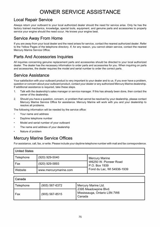
OWNER SERVICE ASSISTANCE
75
Local Repair ServiceAlways return your outboard to your local authorized dealer should the need for service arise. Only he has thefactory trained mechanics, knowledge, special tools, equipment, and genuine parts and accessories to properlyservice your engine should the need occur. He knows your engine best.
Service Away From HomeIf you are away from your local dealer and the need arises for service, contact the nearest authorized dealer. Referto the Yellow Pages of the telephone directory. If, for any reason, you cannot obtain service, contact the nearestMercury Marine Service Office.
Parts And Accessories InquiriesAll inquiries concerning genuine replacement parts and accessories should be directed to your local authorizeddealer. The dealer has the necessary information to order parts and accessories for you. When inquiring on partsand accessories, the dealer requires the model and serial number to order the correct parts.
Service AssistanceYour satisfaction with your outboard product is very important to your dealer and to us. If you ever have a problem,question or concern about your outboard product, contact your dealer or any authorized Mercury Marine dealership.If additional assistance is required, take these steps.1. Talk with the dealership's sales manager or service manager. If this has already been done, then contact the
owner of the dealership.2. Should you have a question, concern, or problem that cannot be resolved by your dealership, please contact
Mercury Marine Service Office for assistance. Mercury Marine will work with you and your dealership toresolve all problems.
The following information will be needed by the service office:• Your name and address• Daytime telephone number• Model and serial number of your outboard• The name and address of your dealership• Nature of problem
Mercury Marine Service OfficesFor assistance, call, fax, or write. Please include your daytime telephone number with mail and fax correspondence.
United States
Telephone (920) 929-5040 Mercury MarineW6250 W. Pioneer RoadP.O. Box 1939Fond du Lac, WI 54936-1939
Fax (920) 929-5893
Website www.mercurymarine.com
Canada
Telephone (905) 567-6372 Mercury Marine Ltd.2395 Meadowpine Blvd.Mississauga, Ontario L5N 7W6Canada
Fax (905) 567-8515

OWNER SERVICE ASSISTANCE
76
Australia, Pacific
Telephone (61) (3) 9791-5822 Mercury Marine Australia132-140 Frankston RoadDandenong, Victoria 3164Australia
Fax (61) (3) 9793-5880
Europe, Middle East, Africa
Telephone (32) (87) 32 • 32 • 11 Marine Power - Europe, Inc.Parc Industriel de Petit-RechainB-4800 Verviers,Belgium
Fax (32) (87) 31 • 19 • 65
Mexico, Central America, South America, Caribbean
Telephone (954) 744-3513 Mercury Marine11650 Interchange Circle NorthMiramar, FL 33025U.S.A.
Fax (954) 744-3535
Japan
Telephone 81-053-423-2500 Mercury Marine - JapanAnshin-cho 283-1HamamatsuShizuoka-ken, Japan 435-0005Japan
Fax 81-053-423-2510
Asia, Singapore
Telephone 5466160 Mercury Marine Singapore72 Loyang WaySingapore, 508762Fax 5467789