40 - 50% CO2 • Often diluted with air (Nitrogen/Oxygen ...
88
These materials were developed under the auspices of CalRecycle for specific technical training presentations and are posted as reference documents for the local government and CalRecycle staff who attended this technical training series. They are not intended to stand alone as informational or training materials. If you require assistance in obtaining access to the presentations, call the Public Affairs Office at (916) 341-6300 or Dennis Corcoran at (916) 341-6395.
Transcript of 40 - 50% CO2 • Often diluted with air (Nitrogen/Oxygen ...

These materials were developed under the auspices of CalRecycle for specific technical training presentations and are posted as reference documents for the local government and CalRecycle staff who attended this technical training series. They are not intended to stand alone as informational or training materials.
If you require assistance in obtaining access to the presentations, call the Public Affairs Office at (916) 341-6300 or Dennis Corcoran at (916) 341-6395.

_____________________________________
PART 1
DESIGN OF LANDFILL GAS SYSTEMS
_____________________________________
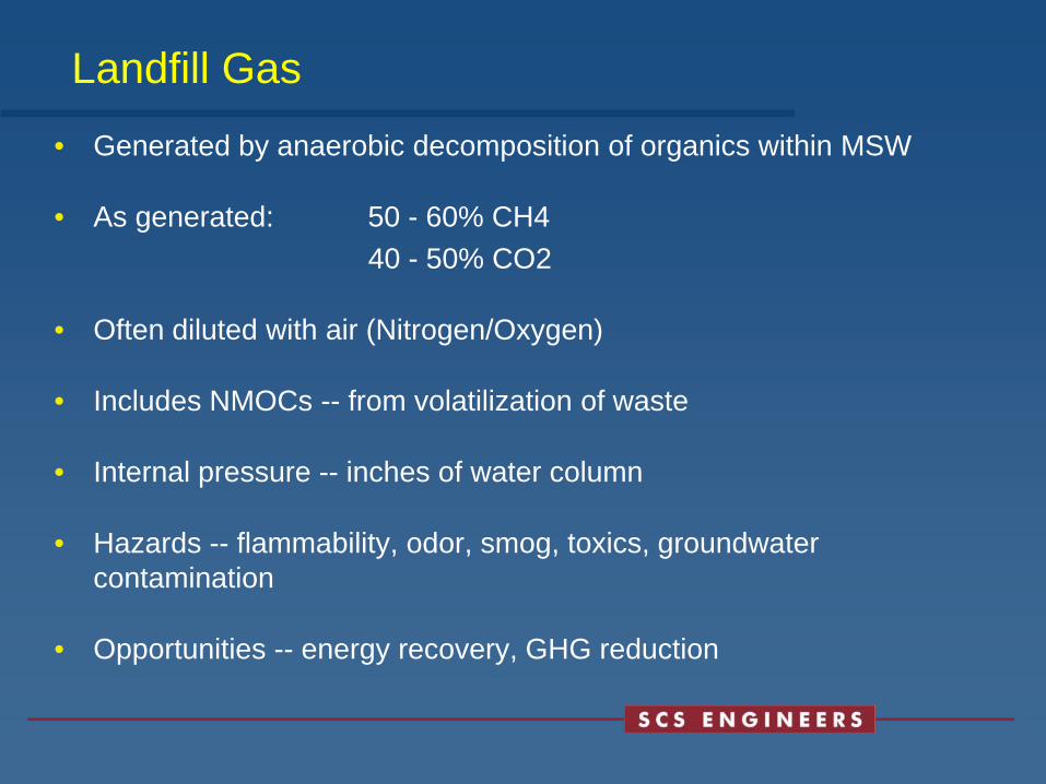
Landfill Gas• Generated by anaerobic decomposition of organics within MSW
• As generated: 50 - 60% CH440 - 50% CO2
• Often diluted with air (Nitrogen/Oxygen)
• Includes NMOCs -- from volatilization of waste
• Internal pressure -- inches of water column
• Hazards -- flammability, odor, smog, toxics, groundwater contamination
• Opportunities -- energy recovery, GHG reduction

Landfill Gas Management System Design Topics to be Covered
• Typical vertical extraction well design concepts
• Typical horizontal collector design concepts
• Effect of cap on LFG collection system performance
• LFG collection piping design concepts
• Source of condensate and condensate management
• LFG destruction/utilization

LFG Collection System Elements
• LFG collection points:
• Typical vertical extraction well design concepts
• Typical horizontal collector design concepts
• Connection to existing vents, wells, etc.
• Effect of cap on LFG collection system performance

LFG Collection System Elements
• LFG collection piping design concepts
• Sources and elements of condensate and condensate management
• Flow control
• LFG destruction/utilization
• LFG blower/combustion device (flare, engine, etc.)

Purposes for Landfill Gas Collection
• Prevent Off-site Subsurface LFG Migration
• Reduce Surface Emissions• Protection of Groundwater• Odor Control• Protection of cover• Other Permit/Regulatory Issues• Generate Revenue (but compliance
issues always govern)
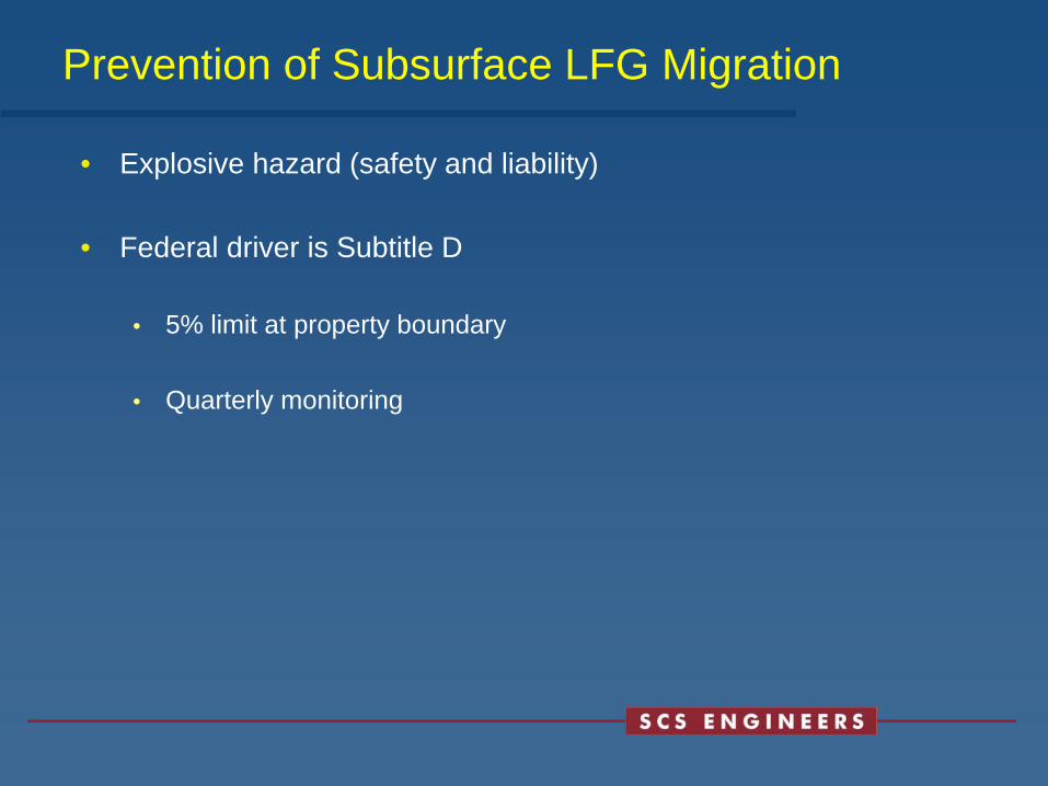
Prevention of Subsurface LFG Migration
• Explosive hazard (safety and liability)
• Federal driver is Subtitle D
• 5% limit at property boundary
• Quarterly monitoring

Prevention of Subsurface LFG Migration (Cont’d)
• State and local regulations are often more definitive than Subtitle D
• Probe design is based on site specific circumstances
• Typically located at property boundary
• Typical horizontal spacing is generally 200 ft to 1000 ft (depending on adjacent land use)
• Probe depth is normally to the depth of refuse or to groundwater

LFG Surface Emissions• LFG is a source of NMOCs and hazardous air pollutants (HAPs).
• NMOCs and NOx combine to form ozone, an ambient air “criteria pollutant”
• HAPs are a subset of NMOCs
• LFG is a major source of greenhouse gas emissions
• Methane and carbon dioxide are greenhouse gases
• Methane has 21 to 25 times the potency of carbon dioxide on a mass basis
• LFG contains odorous compounds
• Regulatory drivers are NSPS/EG regulations and upcoming CARB AB32 Landfill Methane Rule

NMOCs in LFG Can Contaminate Groundwater
• Problem is most prevalent in dry climates, unlined landfills and landfills with no or inadequate LFG collection systems
• Three transfer mechanisms
• Direct LFG to groundwater contact
• Condensation of LFG in vadose zone (below and beyond landfill)
• Condensation of LFG in vadose zone plus washdown (beyond landfill)

Direct Transfer of NMOCs

Transfer of NMOCs by Condensation

Transfer of NMOCs by Condensation and Washdown

LFG Adverse Impact on Landfill Caps
• Soil Cover
• Damage to vegetation (not just an aesthetic issue)
• Damage to vegetation results in increased erosion
• Increases water infiltration and LFG surface emissions
• Membrane Cover
• LFG can produce a gas bubble under the membrane
• Bubble can cause membrane damage
• Potential for membrane damage is greatest during initial membrane installation

Landfill Cap Performance
• Less effective in assisting in total LFG capture
• Cover can bioremediate LFG and reduce odors, methane, and NMOCs
• Cracks in cover are a major source of 500 ppmv exceedances
• More effective in assisting in total LFG capture
• Less air infiltration• Cover may lift (bubble) if
LFG is not removed by LFG collection system
• LFG is very odorous at tears and pinhole leaks

LFG Under Liners or Caps

Vertical Extraction Wells Versus Horizontal Collectors
• Can use either vertical wells or horizontal collectors while refuse is being placed. Horizontal collectors may cause less interference with refuse placement.
• Horizontal collectors must be installed as refuse is being placed. Cannot be installed “after the fact.” Exception is surface collectors
• Vertical wells generally produce better quality LFG (higher methane content) and allow greater operating flexibility
• Horizontal collectors may be more sensitive to damage from differential settlement and leachate flooding

Vertical Extraction Wells Typical Design Parameters
• In-refuse wells are typically drilled to 75% of the refuse depth or until leachate is reached
• Boreholes are typically 24” to 36” diameter
• Typical 200 ft to 400 ft between in-refuse wells
• Casing is PVC, HDPE or carbon steel (infrequently)
• Perforated with slots, holes or screen. Typically perforated in bottom 1/3 to 2/3. Perforations normally start no closer than 20 ft from surface.

Vertical Extraction Wells Typical Design Parameters (Cont.)
• Deeper perforations increase a well’s radius of influence and reduce the potential for air infiltration.
• Wells can be equipped with leachate pumps
• In-soil wells can be used for migration control and sometimes groundwater NMOC migration. They can be equipped with groundwater pumps


Typical Single Completion Well (In-Refuse)
• Well bore seal prevents direct air infiltration along casing
• Gravel pack enhances LFG extraction and reduces screen pluggage
• Wellhead incorporates:
• Flow control valve
• Pressure taps
• Flow monitoring device (optional)
• Thermometer (optional)

Theoretical Zone of Influence of a Landfill Gas Well
• Increases in the vacuum at the wellhead will extend the zone of capture and increase LFG flow at that well
• Influence is assumed to be greater horizontally than vertically
• Variations in vacuum are the operator’s only control tool

Actual Zone of Influence of a Landfill Gas Extraction Well
• Variations in waste characteristics
• Interim cover and cell configuration
• Presence of liquids
A well’s “zone of capture” is unlikely to be ideal due to:
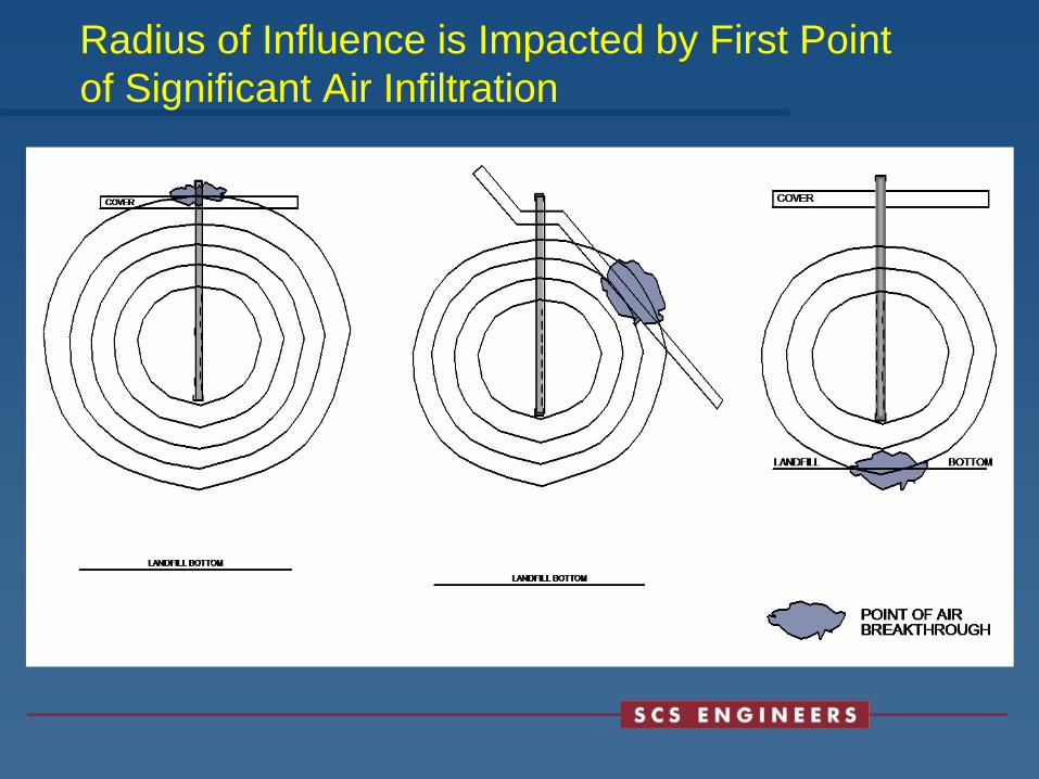
Radius of Influence is Impacted by First Point of Significant Air Infiltration

Well-Spacing vs. Radius of Influence
• Shallower top of collection (perf zone)
• Earlier breakthrough…lower vacuumSmaller ROICloser space needed
• Deeper top of collection (perf zone)
• Higher vacuumLarger ROIGreater spacingRisk of missing shallow LFG

Typical LFG System (Vertical Well) Layout
Equilateral Triangle Arrangement

LFG System Radius of Influence

LFG Collection Efficiency (Capture Ratio)
• LFG collected LFG generated
• Higher ratio more successful migration control
• Generated – Collected = surface emissions
• Can’t be directly measured
• EPA default for comprehensive system = 75%

Extraction Well Installation

Extraction Well Installation

Extraction Wellhead

Horizontal Collectors General Design Parameters• Installed as refuse is being filled
• Typically spaced 100 to 200 ft horizontally and 40 to 60 ft vertically
• They consist of a pipe in a trench filled with porous material (e.g., crushed stone or tire chips)
• Pipe is typically HDPE with holes drilled within or coated CMP or PVC with alternating diameters (nested within each other)
• When used as a single layer just below the landfill surface, and under a membrane cover, they are sometimes called “surface collectors”

Typical Horizontal Collector Arrangements

Typical Horizontal Collector Arrangement


LFG Collection Piping
• Collects LFG and provides a source of vacuum to the wellheads
• Vacuum at flare station should be constant (e.g., –80 inches). Variations from a fixed value at the flare station completely disrupt well field operation
• Design intent is to have more vacuum than necessary at all wells. Wellhead valve is adjusted to reduce vacuum to needed level
• Unusual drops in available vacuum at a well are due to condensate blockages or line breaks

Header System Design Issues
• Above-grade vs. below-grade• Condensate collection/minimum slope (generally 2 to 4%
on refuse and 1 to 2% on native soil)• Size vs. pressure drop (friction lost)• Friction loss – proportional to length, inversely
proportional to square of diameter• Materials (HDPE vs. PVC; CMP; FRP)• Wall thickness/strength (SCH 40 PVC; SDR 11 HDPE)• Looped system• Concurrent vs. countercurrent flow

Typical Header Layout – Loop
B/F STATION

Probe/EW LocationWRONG
RIGHT

Above-Ground Supported Header

Above-Grade PVC Header Line with Supports

Header Placement in Trench

Road Crossing

LFG Condensate
• Condensate volume depends on LFG temperature and flow
• LFG is assumed to be 100% saturated with water
• LFG temperature is typically 90° to 130° F
• LFG cools in the LFG collection piping the moisture condenses out into the piping
• Drains to low points in the piping and can restrict flow
• Above-grad e piping produces more condensate

Problems Caused by LFG Condensate
• Accumulates at low points, restricts flow and vacuum; can completely plug a line
• Can freeze in the piping
• Must be properly disposed of
• Contains trace quantities of NMOCs
• Infrequently (if ever) considered a RCRA hazardous waste
• Very odorous
• Condensate from compression (during LFG utilization) has a much higher hydrocarbon fraction
- May be RCRA hazardous for NMOCs and metals

LFG Condensate Disposal
• Mix with leachate for treatment/disposal with leachate
• Return to landfill, but only in lined cell
• Evaporation via flare injection
• Must be pressure/air or pressure atomized in a nozzle
• Must maintain injection system to prevent flare stack refractory damage
• Flare always has enough excess energy to handle condensate

Typical Condensate Drain

Typical Automatic Condensate Sump

LFG Disposal/Destruction Alternatives
• Destruction• Open flares (aka: candle stick flares or utility flares)
• Enclosed flares (aka: ground flares)
• Beneficial use
• Electric power
• Medium-BTU LFG
• High-BTU LFG
• Leachate evaporation

LFG Disposal/Destruction Alternatives (Cont’d)
• Combined arrangements
• Flare in parallel with beneficial use
• Flare as stand-by to beneficial use

Blower/Flare Station - Design Concepts
• Design for future LFG flow and heat release (mmbtu/hr) with some contingency
• Standby flares are not normally provided
• Typically one standby blower is provided equal to largest blower
• 40 to 80 inches of vacuum most common

Blower/Flare Station - Design Concepts
• Smaller blower/flare stations can be skid-mounted
• Location should consider
• Central to LFG collection system• Electrical service (proper voltage and power)• Public visibility• Keep away from trees!
• Provide available vacuum to entire well field
• 40 to 80 inches vacuum normally provided

Blower/Flare Station Typical Components
• Moisture separator (knockout and demister)
• Blowers (with TEFC motors)
• LFG piping and flame arrestor
• Flow meter
• Pilot fuel supply (normally propane)
• UV flame detector

Blower/Flare Station Typical Components
• MCC and control panel (controls both blower and flare)
• Auto dialer (optional)
• Flare (candlestick or enclosed)
• Auto shutoff valve

Blower Skid
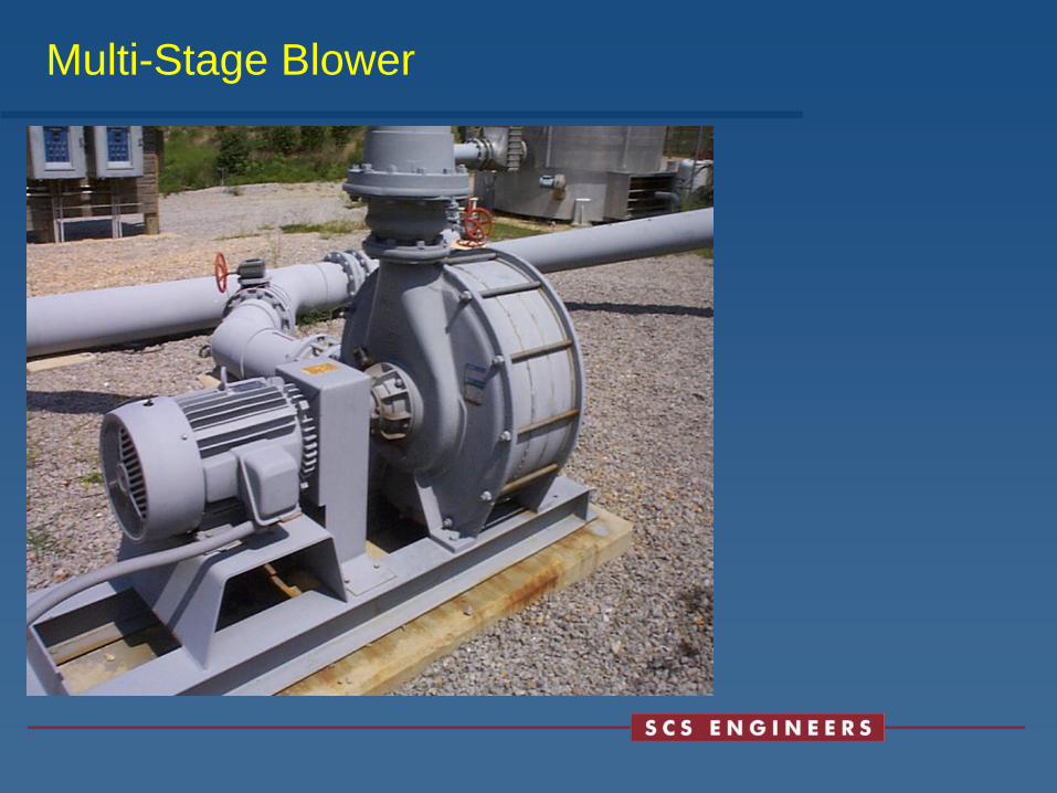
Multi-Stage Blower

Enclosed Ground Flares
• LFG combusted close to ground
• Flame not visible from outside
• Air louvers near stack base
• Can perform emission (stack) test of effluent
• Typical destruction of 98 to 99% (or greater)
• More expensive than candlestick flares

Enclosed Flare Components
• Flare body (aka: stack or shell) – usually circular ( 30 to 40 feet high) cross-section but sometimes square
• Refractory lining – almost always soft and fixed to shell with pins
• Burners
• Combustion air louvers near stack base
• Thermocouples

Enclosed Flare Components (Cont’d)
• Source test ports
• Pilot ignition system
• Flame scanner (aka: fire eye)
• PLC controller

Enclosed Flare Operation
• Destruction is governed by temperature, residence time, and turbulence (mixing) – the so-called three T’s
• Typical operating temperature range: 1,400 °F to 1,600 °F
• Typical residence time: no less than 0.6 seconds
• Mixing is by natural draft – this is the limiting factor on enclosed flare destruction efficiency
• Adiabatic flame temperature of LFG is over 3,500 °F. Excess air is added to lower temperature to 1,500 °F±. Thermocouple drives opening/closing of louvers to regulate temperature.

Flare – Square Cross-Section

Flare – Circular Cross-Section

Flare Louver
Candlestick Flare Components
• Vertical pipe
• Flare tip at top of pipe
• Windshield at top of pipe – flame visible
• Thermocouple
• Spark plug igniter
• Pilot
Candlestick Flare Components
• Smaller than enclosed flare
• Less expensive than enclosed flare
• Typical destruction of 98 percent
• Cannot test effluent
• Note: Will not be allowed under new CARB rule, except for limited time (through 2017 for existing candle flares)

Candlestick Flare

Skid-Mounted Utility Flare

Beneficial Use Technologies
• Electric power generation
• Reciprocating engines
• Combustion turbines
• Steam cycle power plants
• Fuel cells
• Medium-BTU gas sale
• Light clean-up, compression and dedicated pipeline to displace natural gas/or other fossil fuels at end user

Beneficial Use Technologies
• Medium-BTU gas sale (Cont’d)
• Industrial/commercial/institutional boiler fuel
• Utility power plants
• Other industrial uses (dryers, kilns, furnaces, etc.)
• High-BTU gas sale
• Pipeline quality gas
• Vehicle fuel
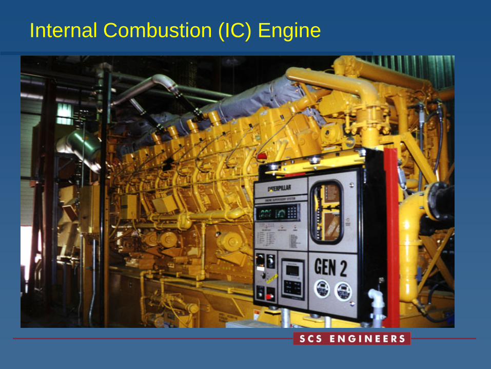
Internal Combustion (IC) Engine
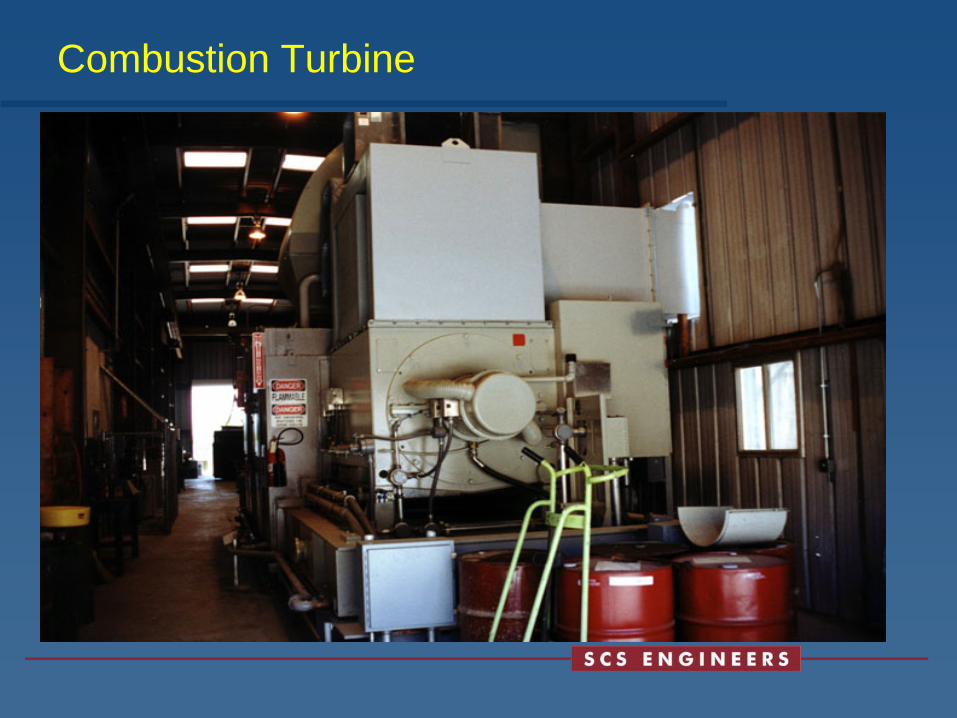
Combustion Turbine
Landfill Gas Collection System Summary
• LFG collection system design and construction
• Site specific
• Not rocket science
• Provide path for LFG collection
• Manage condensate
• Burn the gas
• Always consider operating goals
• Get input from system operators

Probe Functionality Study
• May 2008 CIWMB study:Landfill Gas Monitoring Well Functionality at
20 California Landfills• The following activities were conducted
• Gas Monitoring Assessment
• Video Borescope Inspection
• Initial Condition Assessment
• Vacuum Testing of Probe
• Lithology Evaluation

Probe Functionality Study (cont.)• The study concluded:
• There is no single way in which to evaluate the functionality of a probe
• Current approach to the LFG perimeter migration monitoring probe design, construction, and installation is unsatisfactory
• The study recommended:• Construct probes with longer screened segments
• Assemble probes using threaded coupling
• Construct probes using a valve on the probe head assembly
• Locate probes as far away from vegetation as possible
• Develop standard probe specification and construction criteria
• Requirement for a professional geologist/engineer certification of installed/completed probes
• Periodic functionality assessments

BMPs for LFG Monitoring Probe Construction• Based on Functionality Study, the CIWMB completed a
rulemaking to modify Section 20925
• October 2008 released BMPs:1. Probe should be constructed with longer screened segments (5-ft
minimum)
2. Probes should be assembled using material/manner that provides an adequate seal and does not interfere with sampling
3. Minimize the number of probe pipe connections
4. Probes should be constructed using a non-specialized valve head
5. LFG wells and probes should be properly labeled and identified
6. LFG probes should be constructed to allow access by a bore monitor
7. Probe depth in relation to the water table should be a design consideration

BMPs for LFG Monitoring Probe Construction
• Specific BMPs (cont.):
8. Probes should be preferentially located as far from surface vegetation as possible
9. A certified engineering geologist/registered civil engineer must “field design” the screened interval for the probes and certify installation/completion
CIWMB MPP Review Approach
• Review Approach was published in October 2008 for LEA’s and CIWMB’s review of gas monitoring probe plans:
• LFG well/probe as-builts
• LFG monitoring results
• Boring Logs
• Plot plans showing existing and proposed locations/spacing
• A discussion and map regarding surrounding land uses
• Geologic cross sections and map
• A drawing showing a typical well/probe
• Any other pertinent evidence
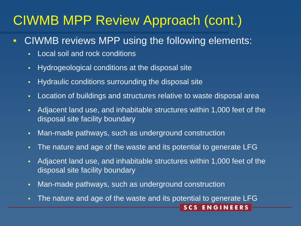
CIWMB MPP Review Approach (cont.)• CIWMB reviews MPP using the following elements:
• Local soil and rock conditions
• Hydrogeological conditions at the disposal site
• Hydraulic conditions surrounding the disposal site
• Location of buildings and structures relative to waste disposal area
• Adjacent land use, and inhabitable structures within 1,000 feet of the disposal site facility boundary
• Man-made pathways, such as underground construction
• The nature and age of the waste and its potential to generate LFG
• Adjacent land use, and inhabitable structures within 1,000 feet of the disposal site facility boundary
• Man-made pathways, such as underground construction
• The nature and age of the waste and its potential to generate LFG

Implementation Issues with Revised Regulations
• CIWMB inclusion in the review and approval process for LFG plans• Rejecting LEA approvals
• Rejecting previously approved alternatives
• Depth of probe must be at or near the maximum depth of waste versus depth of waste within 1000 feet
• Waste close to or at property boundary
• Depth to groundwater• RWQCB has weighed in on regulation
• Criteria for Spacing

END OF PART 1

Convection

Uncontrolled LFG – Concentration Impact

LFG Control – Pressure Impact

LFG Control – Concentration Impact
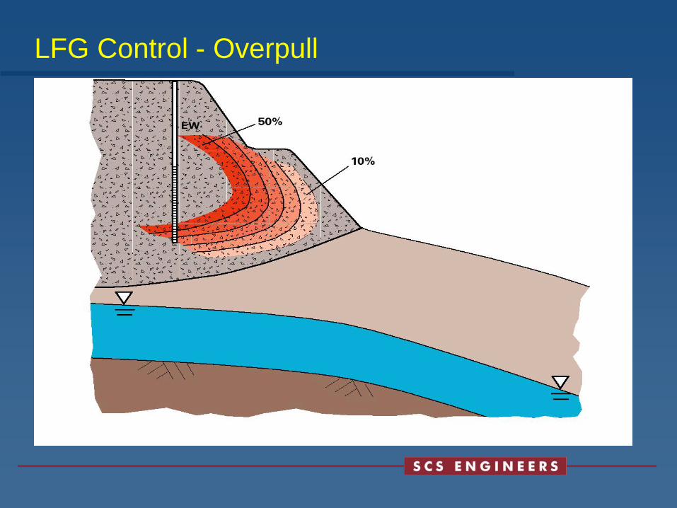
LFG Control - Overpull

Monwell/Probe Spacing
Ideal: dp < dh