4 x NEW Surplus 3,880KW Deutz MWM TCG2032 V16 NG …
17
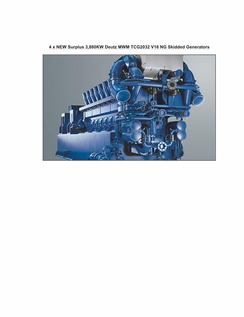
4 x NEW Surplus 3,880KW Deutz MWM TCG2032 V16 NG Skidded Generators
Transcript of 4 x NEW Surplus 3,880KW Deutz MWM TCG2032 V16 NG …
4 x NEW Surplus 3,880KW Deutz MWM TCG2032 V16 NG Skidded Generators
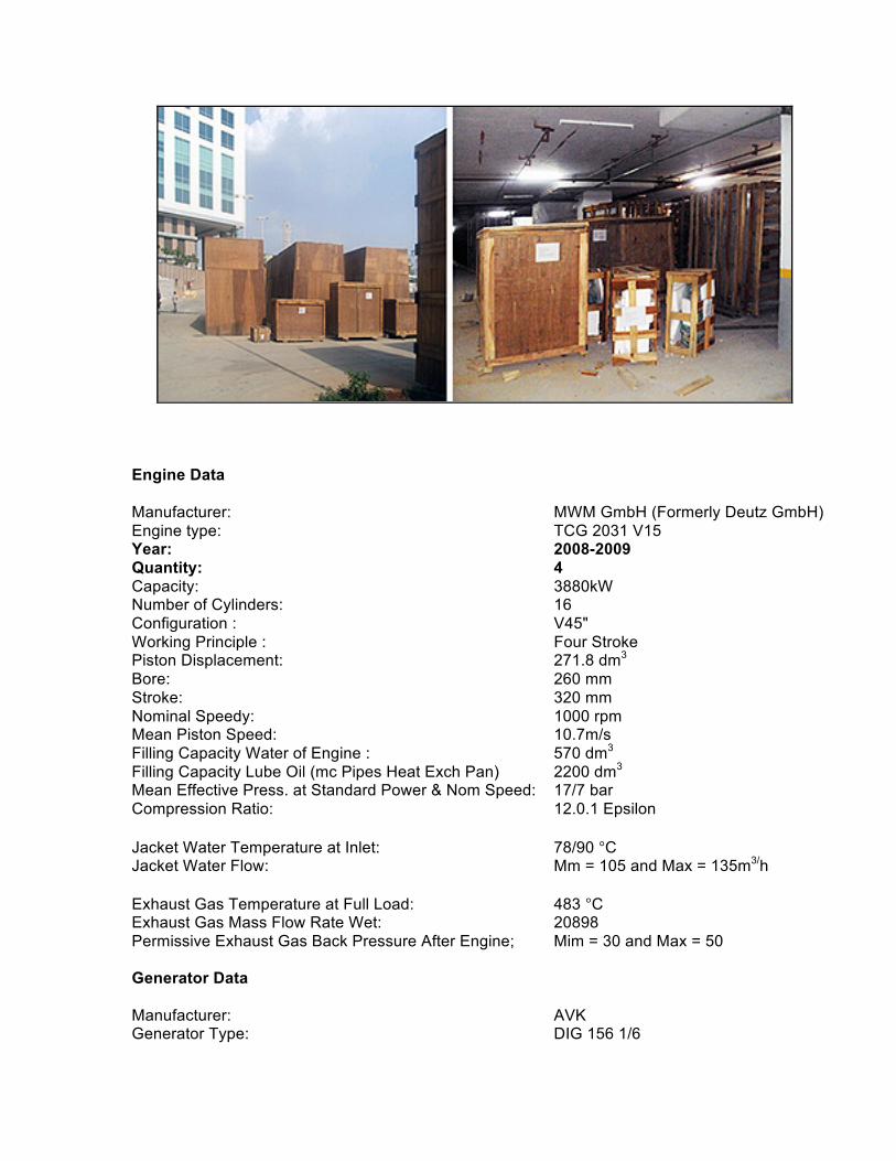
Engine Data Manufacturer: MWM GmbH (Formerly Deutz GmbH) Engine type: TCG 2031 V15 Year: 2008-2009 Quantity: 4 Capacity: 3880kW Number of Cylinders: 16 Configuration : V45" Working Principle : Four Stroke Piston Displacement: 271.8 dm3
Bore: 260 mm Stroke: 320 mm Nominal Speedy: 1000 rpm Mean Piston Speed: 10.7m/s Filling Capacity Water of Engine : 570 dm3 Filling Capacity Lube Oil (mc Pipes Heat Exch Pan) 2200 dm3 Mean Effective Press. at Standard Power & Nom Speed: 17/7 bar Compression Ratio: 12.0.1 Epsilon Jacket Water Temperature at Inlet: 78/90 °C Jacket Water Flow: Mm = 105 and Max = 135m3/h Exhaust Gas Temperature at Full Load: 483 °C Exhaust Gas Mass Flow Rate Wet: 20898 Permissive Exhaust Gas Back Pressure After Engine; Mim = 30 and Max = 50 Generator Data Manufacturer: AVK Generator Type: DIG 156 1/6
Frequency: 50Hz Voltage: 11000 V Current: 254 A Nominal Rating: 4845 KVA Voltage Range: ±5 Temperature Rise: F Isolation Class: F Protection Class: IP 23 Nominal Speed: 1000 rpm Genset Weights and Dimensions Weight Empty: 49800kg Width: 2750 mm Length: 6880 mm Height: 3820 mm 1. Base engine Modern stationary 4-stroke Otto gas engine with lean-mix combustion; 16 cylinder V-engine, water cooled with exhaust gas turbo mixture charging and mixture cooling; direction of rotation in accordance with DIN 6265, anti-clockwise (seen from flywheel side) Crankcase Sphero-cast case with added cooling water mantle, dimensionally stable due to high side walls; with suspended crankshaft and cross-bolted bearing seats; bottom mounting cylinder liners; short, cut-free lube oil supply bores from the hollow camshaft as main oil distribution pipes to all lubricating points; side drive room openings with quick-close covers; wet cylinder liners made from highly wear resistant special spun type casting; rotationally symmetrical, non warping liner support; crankcase ventilation via the oil trap Driving Gear Crankshaft made from chrome molybdenum steel with screwed-on counterweights and hardened main and con-rod bearing pegs; double-ended con rods made from alloyed steel, forged with slanted toothed joint faces, oil supply for piston bolts and pistons through the drilled con rod, stepped piston bolt bearing for reduced bearing and piston damage, guide in piston; ESG (electron ray welded) light metal piston with asymmetric crowned compression ring, tapered compression piston ring and an oil scraper ring, all piston rings with highly wear resistant chrome coating; main and con-rod bearings as ready-to-install ternary bearings (steel support shells with leaded bronze, "sputtered* running surface); camshaft made from steel, bearings and cams hardened, bearing bushes made from aluminum alloy, drive via toothed wheels: flywheel, Cylinder Head
Individual cylinder heads made from special cast iron with false floor and cooling bores in the combustion chamber plate for mechanical and thermal relief; four valve and inserted seatrings. outlet seatrings water-cooled and armor-plated, mixture supply from the distributor line into the vee; exhaust gas conveyance on the same side upwards in the vee, new modular unit (Unit) made up of cylinder head, bushing and intermediate case with pistons and con-rods as well as manifold, exhaust, lube oil and cooling water pipe segments for easy installation and simple servicing; chamber spark plugs central in combustion chambers with intensive plug seat cooling Valve Drive One toothed wheel driven hollow-drilled camshaft on each side of engine made up of individual components for each cylinder, simultaneous main lube oil distribution line; valve actuation for every 2 inlet & outlet valves, stop rod; toggle lever & valve bridge, o-ring oil seals on valve shafts Ignition Microprocessor-controlled high voltage ignition system with low voltage distribution, one ignition coil per cylinder; without moving parts: wear-free: triggered via the crown gear of the flywheel and a feeder on the camshaft: variable ignition times; firing power and distribution via computer to the primary side of the ignition coils; industrial engine or special spark plugs with greater running performance; durable Teflon spark plug connectors firing power buffered by 24 V battery Antiknock Regulation Knock sensor monitoring for each cylinder; individual cylinder ignition regulation, adjustment of gas-air mixture and engine power, knock-free operation with highest possible power output with highest efficiency whilst maintaining the emission limits Carburation Air intake via paper dry-type air filters in the mixer; gas supply from the safety gas control line; dosing of the proportion of gas and air in the DEUTZ Power Systems multi-gas mixer Mixture Charging Two exhaust gas turbochargers suck air and gas out of the gas mixer under atmospheric pressure; subsequent compression of the gas mixture and re-cooling in the 2-step mixture coolers (low temperature step in separate cooling circuit); rotary disc valve throttling device for each cylinder row after mixture cooler for power regulation Gas Mixture Regulation and Monitoring Electronic regulation and monitoring of the air-gas mixture on the mixer servomotor via combustion chamber temperature (1 temperature sensor per cylinder) and the power/speed, summarized in the DEUTZ Power Systems TEM system. Starter
1 Compressed air starter turbine with integrated gearbox and 24V solenoid valve, pressure reduction station with ballcock and filter, as well as connections for turning engine compressed air supply and the gas control line electro-pneumatic valve; flanged to the engine casing Lube Oil System Pressure lubrication using a gear pump, lube oil cooling in separate cooling circuit; oil filter in main flow; additional fine filter in bypass flow; automatic lube oil refilling in the oil pan through controlled intake; automatic pre-lubrication via electric pump; oil removal via same pump on the genset; lube oil pre-heating using separate electric circulation pump and plate heat exchanger. Cooling Water Connections Rubber compensators with companion flange for connection to the cooling water pipes Exhaust Gas Connection 2 stainless steel compensators to be fixed using tightening clamps with respective weld-on flanges for connection to the exhaust gas pipe Sensor technology/actuator technology and cabling Sensors for cooling water temperature, suction intake air temperature, mixture temperature, oil temperature, oil level, oil pressure, speed, combustion chamber temperature, exhaust gas temperature, exhaust gas turbocharger speed, crankcase pressure, starter air pressure, gas mixer position logging, knock sensors, differential pressure crankcase ventilation fan and servomotor throttling device, servomotor gas mixer, control of cooling water pre-heater. Spark plugs fully cabled to two central connection elements using detachable connections Engine Test Run The engines undergo an engine test run in the manufacturer's factory. The test runs take place on calibrated test stands. Testing procedure and content: Testing - General Engine installation and cabling in accordance with the design plan Engine set-up on test stand with cold functions test Running in the engine in accordance with the run-in program Driving gear check Engine regulation and leak check Engine acceptance test 60 mm 100% power output at rated speed 2 measurements 20 min 50% power output 1 measurement Regulator trial 100% at zero load
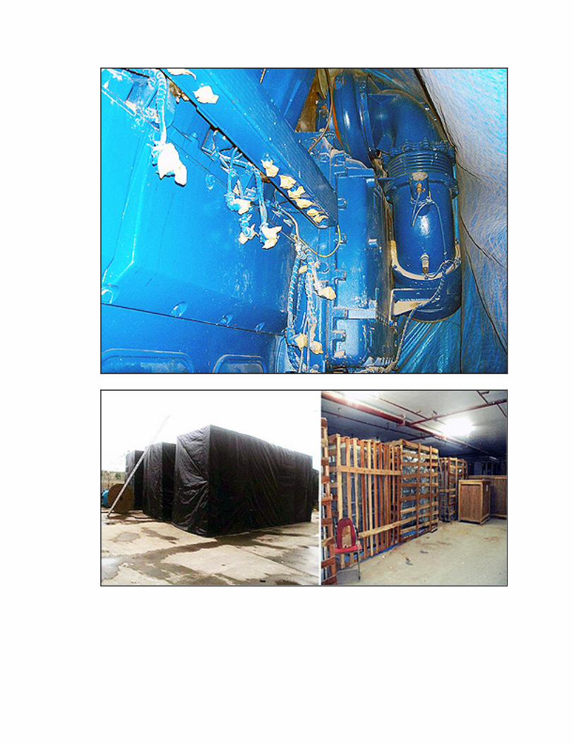
Measured Value Acceptance Speed, brake pressure, power output, consumption, regulator, exhaust gas temperature, suction intake air temperature, lube oil pressure, lube oil temperature cooling water pressure, cooling water temperature charge pressure, charge temperature, exhaust gas emissions (% 02 dry.mg/m'n NOx) Preservation Standard preservation of the engine to protect against corrosion during transportation and any subsequent storage at its destination Maximum protection period of 6 months after delivery, when stored in a closed dry room. 3. Scope of Supply Manufacturer: AVK Type ; DIG 156 L/6, 11000 V. 50 Hz Construction The generator consists of the main generator as the internal pole machine and the exciter generator as the external pole machine The power supply of the voltage regulator is produced in conjunction with the rated voltage Stator The stator casing is designed as a weldment. The stator package is made from hydraulically compressed matt dynamo sheet and has been compressed together with the stator to form a compact unit by using pressure plates The stator winding corresponds to insulation class F in accordance with VDE 0530/IEC 34. The end windings and connections are supported by suitable fastenings and arc mechanically connected to one another, which protects them against dynamic stress from electrodynamics forces. Rotor The rotor consists of the shaft and the main magnet wheel. The main magnet wheel - in salient pole design - is made of hydraulically compressed sheet metal or steel plate. A dampening cage made from copper is installed as standard, which is electrically connected to the pole shoes as well as between the poles. The main rotor windings are made from flat copper and are protected against centrifugal forces by suitable components. The rotor winding corresponds to insulation class F in accordance with VDE 0530/IEC 34 The rotor is balanced with half feather keys in accordance with VDE 0530/IEC 34, part 14. Bearing Plates
The bearing plates are welded or made from cast iron The generator feet are attached directly under the bearings in accordance with the design. Bearings Anti-friction bearings on the drive side designed as detachable bearings and on the non-drive side as fixed bearings. Regulations, Standards Construction regulations: VDE 0530, IEC 34 (EN 60034). ISO 8528-3 Components/modules/standard design Large size terminal box for installation of current transformers. Terminal boxes with cable sockets and cable strain relief. Electronic regulation Base module "Cosimat N+": • Highly stable current regulation • PID control characteristic setting • Reactive current dependent droop • Under speed protection through U/F function • Connection for function components Function components Cos-phi regulator: Cos phi trimmer
• The power factor of the regulated generator is the same as that of the overall current or the current of the other generators (depending on the current transformer connection) • Suitable for parallel operation with generators without linear voltage droop • Generators protected via adjustable over and under excitation margins • Setpoint adjustment using potentiometer or voltage signal 4 20 mA
Voltage Trimmer: Automatic synchronous trimmer
• Automatic trimming of generator idling speed voltage to the supply voltage before synchronization • Saves separate voltage trimming by additional devices in the switching system
Exciter and Diode Monitoring: Exciter system monitoring - DC. relay.
Supplied loose for installation the monitoring/electric control panel

• Recording of over and under excitation states • Recording of errors in the rotating diodes using the irregularity of the exciter DC. current
Voltage setpoint regulator The adjustable voltage potentiometer (500 Ohm)
for manual voltage adjustment is supplied loose for installation the electrical control panel
Droop Current Transformer: For parallel operation with the power supply
and with one another, installed in the generator.
Stationary Heating: Installed in the generator Temperature Monitoring: 6 PT 100 sensor for winding Electrical data and properties Voltage operating range Between 95 ... 105 % of the rated voltage Voltage adjustment range +/- 5 % rated voltage for continuous
operation +/-10 % short-term (testing or synchronization)
Voltage accuracy, static +/- 0,5 ... 1 % Continuous short circuit current With 3-pole terminal short circuit minimum
3 x rated current for 3 s Overload capacity 10 % for 1 hr, within 6 hrs. or In accordance with IEC 34A/DE 0530, i.e.
50 % for 30 s Overspeed In accordance with VDE 0530 for 1.2 times
rated speed for 2 min 2.2 Genset Components 8ase frame Steel bend and torsion-resistant construction to take the engine and the generator. Elastic bearings are mounted under the base frame. Coupling High-stretch, axial plug-in flange coupling for torsional elastic connection of engine and generator. The disc-shaped rubber body cushions torsional oscillations to a large extent. The rubber element is radially interchangeable. Oil level regulation
Tank mounted on the base frame and connected to / communicating with the oil pan Dip sensor integrated into the tank with contacts for oil level monitoring (min./max) or to control solenoid valves and fresh oil pump for automatic lube oil refilling. Pre-lube Pump Pre-lubrication though an electric pump on the genset; emptying also possible with the same pump after changing the position of a built-in three-way tap Cooling Water Pre-heating Electrical cooling water pre-heating (heat power output approx. 18 kW) with circulating pump, integrated into the genset and fully cased Additional Genset Parts The following list of components are supplied "loose" and are not mounted on the genset. Installation must be carried out on site by the client. if installation of these components by DEUTZ Power Systems is not listed in the services and supply index (see section 3.12).
• 1 set of maintenance-free steel springs with height adjustment for easy alignment of the genset on the on site foundation. Vibration insulation of approx. 88 - 94 % is achieved with these bearings Structure-borne noise is reduced by a rubber woven plate on the underside of the beanngs • 2 solenoid valves with connections for lube oil inflow • 1 fan for ventilating the crankcase with integrated filtering of the oil spray fumes to dispose of the exhaust air • 1 differential pressure sensor to monitor the crankcase ventilation fan • 1 tin of RAL 5010 repair paint
2.2.1 Air Preheater and Filter Unit
The combustion pre-heater provides a constant combustion air temperature in the engine suction line. The following components are within the scope of supply and are supplied "loose".
• 1 unit consisting of two casings (one casing for each cylinder row) in which an air-water heat exchanger and 4 filter plates are installed The filter plates are fitted with easily detachable covers for quick and easy, tool-less exchange For easy monitoring of the filter plate contamination, a pressure gauge is fitted in the casing to display low pressure • 2 durable special hoses for connection between the gas mixer and the air pre-heatlng. unit • 4 hose clips to fix the special hoses • 1 three-way valve DN 32 for regulating the amount of cooling water in the air-water heat exchanger
2.3 Genset Assembly

Installation
Gas engine and generator elastically coupled mounted on the same base frame, for vibration- proof installation via springs on the on-site foundation.
2.4 Zero-Pressure Gas Control Line With Connection Accessories Loose Supply, On-Site Installation
Gas type: Natural Gas Nominal width: DN 100-125
Safety gas control line as a compact unit in accordance with the DVGW certification body
Operating side with gas flow direction to the right (option to the left), consists of:
• 1 ballcock • 1 gas filter • 1 pressure gauge • pressure sensor • solenoid valves • 1 zero-pressure regulator • outlet fitting • companion flanges for installing the gas control line in the gas pipe
The gas control line is designed for a gas flow pressure of Min = 130 mbar and Max = 150 mbar. deviation frequency < 1/6 min The gas control line components can vary slightly according to the type of gas and operation. If an order is placed, the separate itemized list is binding.
2.5 TEM EVO System
The DEUTZ Power Systems Total Electronic Management (TEM) system includes the control and monitoring of all functions of a gas engine and the engine auxiliary drive in one unit Through the monitoring functions it protects the engine against unauthorized boundary states and guarantees long service life The TEM EVO system regulates and optimizes the gas combustion in the cylinders. Integrated control functions ensure optimized and reproducible engine values in all operating conditions. Through a wide range of options it is possible to adapt the TEM EV system optimally to suit specific applications. For a generator genset provision need only be made for contactors, a synchronization device, generator/mains protection and a wattmeter in auxiliary genset switch cabinet over and above TEM EVO system. Set-Up
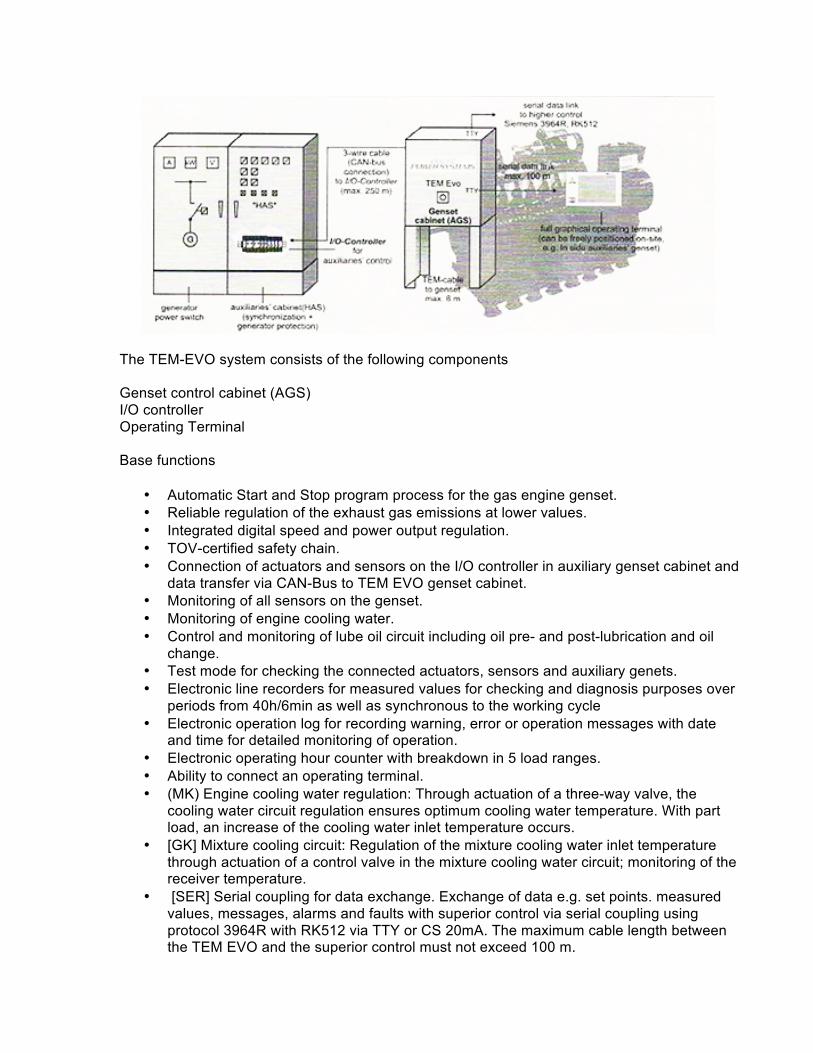
The TEM-EVO system consists of the following components Genset control cabinet (AGS) I/O controller Operating Terminal Base functions
• Automatic Start and Stop program process for the gas engine genset. • Reliable regulation of the exhaust gas emissions at lower values. • Integrated digital speed and power output regulation. • TOV-certified safety chain. • Connection of actuators and sensors on the I/O controller in auxiliary genset cabinet and
data transfer via CAN-Bus to TEM EVO genset cabinet. • Monitoring of all sensors on the genset. • Monitoring of engine cooling water. • Control and monitoring of lube oil circuit including oil pre- and post-lubrication and oil
change. • Test mode for checking the connected actuators, sensors and auxiliary genets. • Electronic line recorders for measured values for checking and diagnosis purposes over
periods from 40h/6min as well as synchronous to the working cycle • Electronic operation log for recording warning, error or operation messages with date
and time for detailed monitoring of operation. • Electronic operating hour counter with breakdown in 5 load ranges. • Ability to connect an operating terminal. • (MK) Engine cooling water regulation: Through actuation of a three-way valve, the
cooling water circuit regulation ensures optimum cooling water temperature. With part load, an increase of the cooling water inlet temperature occurs.
• [GK] Mixture cooling circuit: Regulation of the mixture cooling water inlet temperature through actuation of a control valve in the mixture cooling water circuit; monitoring of the receiver temperature.
• [SER] Serial coupling for data exchange. Exchange of data e.g. set points. measured values, messages, alarms and faults with superior control via serial coupling using protocol 3964R with RK512 via TTY or CS 20mA. The maximum cable length between the TEM EVO and the superior control must not exceed 100 m.
• (IOC) I/O controller. The auxiliary gensets. pumps, valves etc., are controlled via the I/O controller and the related measured values recorded The I/O controller is supplied loose for installation into the auxiliary genset switch cabinet
• (16M) 16 parametrizable messages: Digital entries with extensive parameterizing options, in order to be able to connect system-specific faults, alarms or messages directly to the TEM EVO system With this, the monitoring of a genset is considerably simplified and made much clearer through the recording function in the operation log The parametrizable messages are additionally displayed as potential-free contacts (openers) in the TEM auxiliary genset switch cabinet on the I/O controller.
• (AKRK])Antiknock regulation: Highly dynamic antiknock regulation for each cylinder individually for safe operation of the engine even when using a gas of low methane number Maximum high power at optimum efficiency whilst observing the emission limit values.
• (NATL2) Flexible monitoring of the exhaust gas temperature after exhaust gas Turbocharger A and B Display (mask, history, serial coupling) and flexible monitoring of the exhaust gas temperature after the exhaust gas turbocharger. If a parametrizable limit value is exceeded, a fault is released.
• (SATL2) Measurement and limitation of exhaust gas turbocharger speeds Display (mask, history, serial coupling) and limitation of the exhaust gas turbocharger speeds
• (GL) Monitoring of the generator bearing temperatures Display (mask, history, serial coupling) and monitoring of both generator bearing temperatures. If a parametrizable limit value is exceeded, a fault or alarm is released
• (GLT])The TEM-EVO measures and monitors the temperature of the main engine bearing for engine protection. Exceeding a limit value results in an alarm and finally in a fault.
• (AVW) The TEM-EVO controls the air inlet pre-heating by actuating the control valve of the pre-heating circuit When pre-heating is requested the temperature of air inlet is controlled.
• (VAWTA/SWT) Measurement of heating water temperature before exhaust gas heat exchanger and before lube oil heat exchanger
• (SPC) Connection for maintenance PC Robust service socket on the TEM EVO genset switch cabinet With the connection of the maintenance PC, a control unit interrupts the
connection to the operating terminal or modem The TEM EVO system can then be operated via the maintenance PC
• (2xNKAT) Display in mask of operator terminal and continuous monitoring of exhaust temperature after catalytic converter Exceeding a parametrizable limit value for the exhaust temperature results in a fault.
Operation
An intelligent operating terminal allows access to all functions and thus easy operation of the TEM-Evo system The operating terminal has a 15"-TFT touch display The touch function of the operating terminal allows an simple and intuitive operation of the genset. With the navigator area the operator can change direct and fast into the de-sired mask to operate the genset Every mask shows the status line at the bottom with all major information of the genset status. All control, service and monitoring functions are easily operated without long training times The operating unit can be freely located, as desired directly on the genset or at a distance Of up to 100 m from the genset in a switchboard gallery. Configurations with operating terminals at each genset and/or a central operating terminal are also possible. The user can communicate with the system in his national language The desired language can be activated by simply
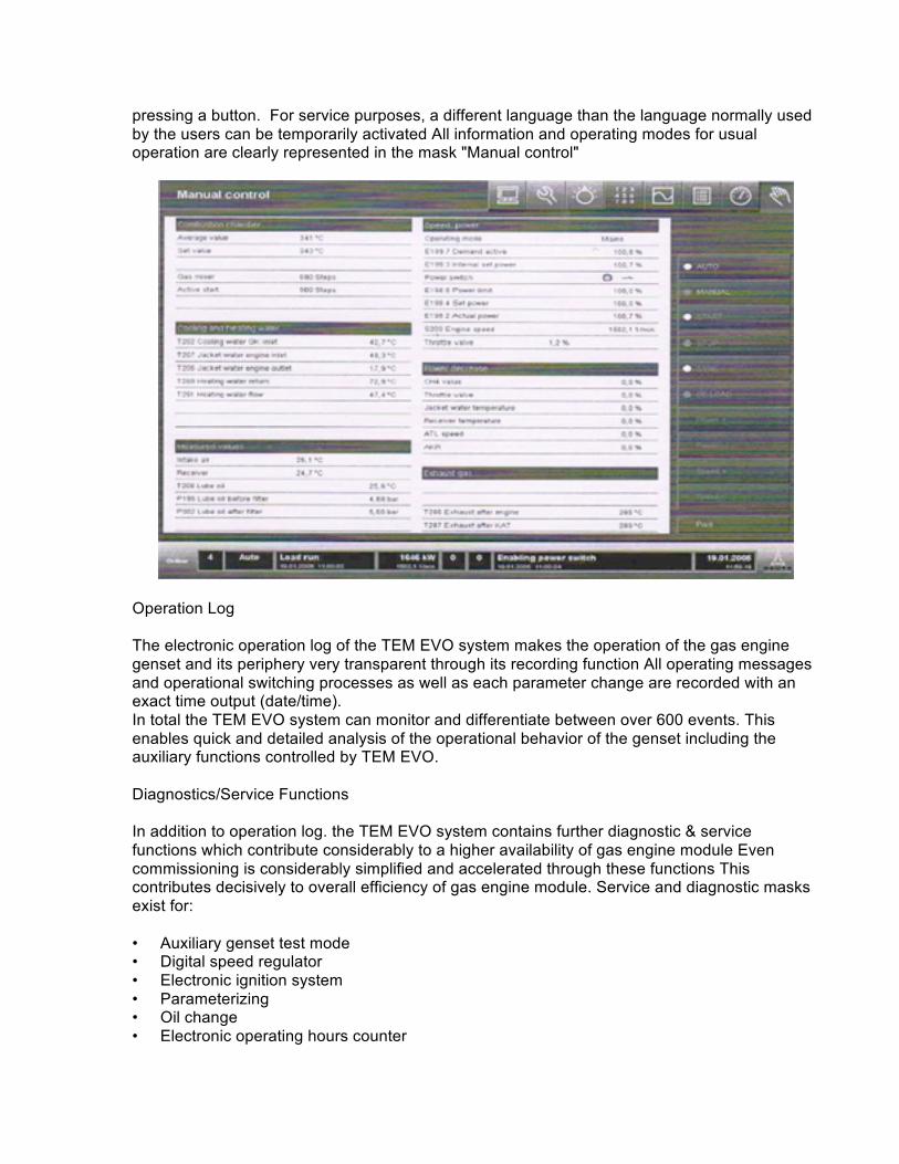
pressing a button. For service purposes, a different language than the language normally used by the users can be temporarily activated All information and operating modes for usual operation are clearly represented in the mask "Manual control"
Operation Log The electronic operation log of the TEM EVO system makes the operation of the gas engine genset and its periphery very transparent through its recording function All operating messages and operational switching processes as well as each parameter change are recorded with an exact time output (date/time). In total the TEM EVO system can monitor and differentiate between over 600 events. This enables quick and detailed analysis of the operational behavior of the genset including the auxiliary functions controlled by TEM EVO. Diagnostics/Service Functions In addition to operation log. the TEM EVO system contains further diagnostic & service functions which contribute considerably to a higher availability of gas engine module Even commissioning is considerably simplified and accelerated through these functions This contributes decisively to overall efficiency of gas engine module. Service and diagnostic masks exist for: • Auxiliary genset test mode • Digital speed regulator • Electronic ignition system • Parameterizing • Oil change • Electronic operating hours counter
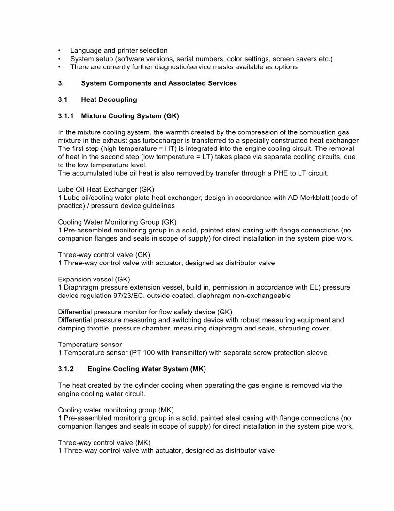
• Language and printer selection • System setup (software versions, serial numbers, color settings, screen savers etc.) • There are currently further diagnostic/service masks available as options 3. System Components and Associated Services 3.1 Heat Decoupling 3.1.1 Mixture Cooling System (GK) In the mixture cooling system, the warmth created by the compression of the combustion gas mixture in the exhaust gas turbocharger is transferred to a specially constructed heat exchanger The first step (high temperature = HT) is integrated into the engine cooling circuit. The removal of heat in the second step (low temperature = LT) takes place via separate cooling circuits, due to the low temperature level. The accumulated lube oil heat is also removed by transfer through a PHE to LT circuit. Lube Oil Heat Exchanger (GK) 1 Lube oil/cooling water plate heat exchanger; design in accordance with AD-Merkblatt (code of practice) / pressure device guidelines Cooling Water Monitoring Group (GK) 1 Pre-assembled monitoring group in a solid, painted steel casing with flange connections (no companion flanges and seals in scope of supply) for direct installation in the system pipe work. Three-way control valve (GK) 1 Three-way control valve with actuator, designed as distributor valve Expansion vessel (GK) 1 Diaphragm pressure extension vessel, build in, permission in accordance with EL) pressure device regulation 97/23/EC. outside coated, diaphragm non-exchangeable Differential pressure monitor for flow safety device (GK) Differential pressure measuring and switching device with robust measuring equipment and damping throttle, pressure chamber, measuring diaphragm and seals, shrouding cover. Temperature sensor 1 Temperature sensor (PT 100 with transmitter) with separate screw protection sleeve 3.1.2 Engine Cooling Water System (MK) The heat created by the cylinder cooling when operating the gas engine is removed via the engine cooling water circuit. Cooling water monitoring group (MK) 1 Pre-assembled monitoring group in a solid, painted steel casing with flange connections (no companion flanges and seals in scope of supply) for direct installation in the system pipe work. Three-way control valve (MK) 1 Three-way control valve with actuator, designed as distributor valve
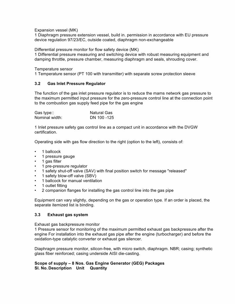
Expansion vessel (MK) 1 Diaphragm pressure extension vessel, build in. permission in accordance with EU pressure device regulation 97/23/EC, outside coated, diaphragm non-exchangeable Differential pressure monitor for flow safety device (MK) 1 Differential pressure measuring and switching device with robust measuring equipment and damping throttle, pressure chamber, measuring diaphragm and seals, shrouding cover. Temperature sensor 1 Temperature sensor (PT 100 with transmitter) with separate screw protection sleeve 3.2 Gas Inlet Pressure Regulator The function of the gas inlet pressure regulator is to reduce the mams network gas pressure to the maximum permitted input pressure for the zero-pressure control line at the connection point to the combustion gas supply feed pipe for the gas engine Gas type:: Natural Gas Nominal width: DN 100 -125 1 Inlet pressure safety gas control line as a compact unit in accordance with the DVGW certification. Operating side with gas flow direction to the right (option to the left), consists of: • 1 ballcock • 1 pressure gauge • 1 gas filter • 1 pre-pressure regulator • 1 safety shut-off valve (SAV) with final position switch for message "released" • 1 safety blow-off valve (SBV) • 1 ballcock for manual ventilation • 1 outlet fitting • 2 companion flanges for installing the gas control line into the gas pipe Equipment can vary slightly, depending on the gas or operation type. If an order is placed, the separate itemized list is binding. 3.3 Exhaust gas system Exhaust gas backpressure monitor 1 Pressure sensor for monitoring of the maximum permitted exhaust gas backpressure after the engine For installation into the exhaust gas pipe after the engine (turbocharger) and before the oxidation-type catalytic converter or exhaust gas silencer. Diaphragm pressure monitor, silicon-free, with micro switch, diaphragm. NBR; casing; synthetic glass fiber reinforced; casing underside AISI die-casting. Scope of supply – 8 Nos. Gas Engine Generator (GEG) Packages Sl. No. Description Unit Quantity
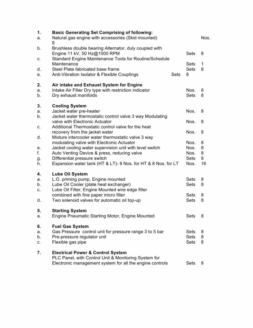
1. Basic Generating Set Comprising of following: a. Natural gas engine with accessories (Skid mounted) Nos. 8 b. Brushless double bearing Alternator, duly coupled with
Engine 11 kV, 50 Hz@1000 RPM Sets 8 c. Standard Engine Maintenance Tools for Routine/Schedule
Maintenance Sets 1 d. Steel Plate fabricated base frame Sets 8 e. Anti-Vibration Isolator & Flexible Couplings Sets 8 2. Air intake and Exhaust System for Engine a. Intake Air Filter Dry type with restriction indicator Nos. 8 b. Dry exhaust manifolds Sets 8 3. Cooling System a. Jacket water pre-heater Nos. 8 b. Jacket water thermostatic control valve 3 way Modulating
valve with Electronic Actuator Nos. 8 c. Additional Thermostatic control valve for the heat
recovery from the jacket water Nos. 8 d. Mixture intercooler water thermostatic valve 3 way
modulating valve with Electronic Actuator Nos. 8 e. Jacket cooling water supervision unit with level switch Nos. 8 f. Auto Venting Device & press, reducing valve Nos. 8 g. Differential pressure switch Sets 8 h. Expansion water tank (HT & LT)- 8 Nos. for HT & 8 Nos. for LT Nos. 16 4. Lube Oil System a. L.O. priming pump, Engine mounted Sets 8 b. Lube Oil Cooler (plate heat exchanger) Sets 8 c. Lube Oil Filter, Engine Mounted wire edge filter
combined with fine paper micro filter Sets 8 d. Two solenoid valves for automatic oil top-up Sets 8 5. Starting System a. Engine Pneumatic Starting Motor, Engine Mounted Sets 8 6. Fuel Gas System a. Gas Pressure control unit for pressure range 3 to 5 bar Sets 8 b. Pre-pressure regulator unit Sets 8 c. Flexible gas pipe Sets 8 7. Electrical Power & Control System
PLC Panel, with Control Unit & Monitoring System for Electronic management system for all the engine controls Sets 8