4 Turbine and Condenser Modernization
8
page 1 / 8 © Siemens AG 2006. All rights reserved. POWER-GEN Europe 30 th May – 01 st June 2006 Cologne, Germany Turbine and Condenser Modernization in the Farge Power Plant as an example of One Source of Competence Richard Bednorz Siemens Power Generation (PG) Mellinghofer Str. 55 45473 Mülheim, Germany Fritz Henken-Mellies Kraftwerk Farge Berner Fährweg 2 28777 Bremen, Germany
Transcript of 4 Turbine and Condenser Modernization

8/9/2019 4 Turbine and Condenser Modernization
http://slidepdf.com/reader/full/4-turbine-and-condenser-modernization 1/8
page 1 / 8 © Siemens AG 2006. All rights reserved.
POWER-GEN Europe30
thMay – 01
stJune 2006
Cologne, Germany
Turbine and Condenser Modernization inthe Farge Power Plant as an example of
One Source of Competence
Richard BednorzSiemens Power Generation (PG)
Mellinghofer Str. 5545473 Mülheim, Germany
Fritz Henken-MelliesKraftwerk Farge
Berner Fährweg 228777 Bremen, Germany
8/9/2019 4 Turbine and Condenser Modernization
http://slidepdf.com/reader/full/4-turbine-and-condenser-modernization 2/8
page 2 / 8 © Siemens AG 2006. All rights reserved.
1. Introduction
Farge Power Plant is located in the north of Germany in Bremen. It is owned by theGerman power supplier E.ON.
Farge PP is a 350 MW , coal fired power station with a Siemens PG Steam Turbineconsists of HP, IP and 2 LPs and a Siemens PG hydrogen cooled generator. Thestation was commissioned in 1967. After more then 30 years of operation it hasaccumulated approximately 200.000 working hours with nearly 4400 starts and stops.
Farge staff operate also the Huntorf Power Plant which is located close by. It is an airstorage gas turbine peak load power plant with a capacity of 290 MW.
2.1 Efficiency increasing measures
After more then 30 years of operation, in the year 2004 a number of measures for
efficiency improvement and power increase should be realized at the Farge PowerPlant.
With the planned measures the project should fundamentally improve the marketposition of the plant and extend its life time.
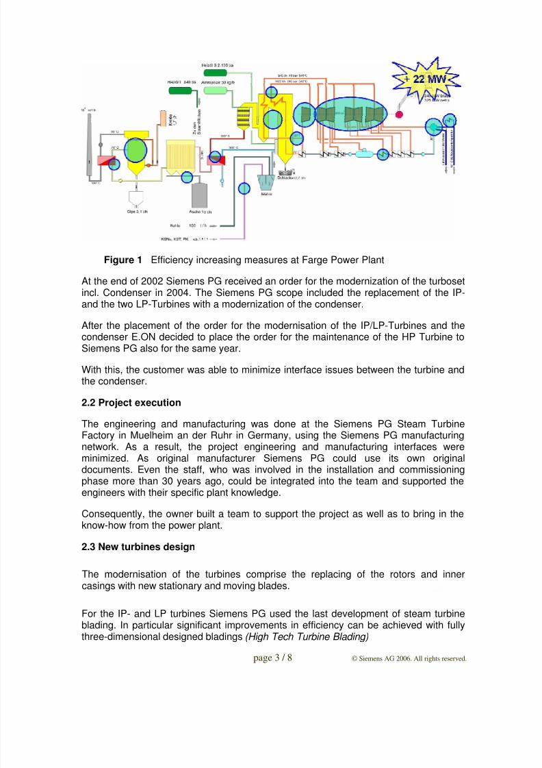
The intension was to get more than 22 MW with following measures:
• New IP-/LP- turbines (rotors and inner casings each)
• New Condenser
• Maintenance of the HP Turbine
• Flow optimization at DeSOx
• Flow optimization at overheater
• Soot blower optimization
• Other smaller improvements
Figure 1 shows all the area in the plant where measures for efficiency improvementwere planed.
8/9/2019 4 Turbine and Condenser Modernization
http://slidepdf.com/reader/full/4-turbine-and-condenser-modernization 3/8
8/9/2019 4 Turbine and Condenser Modernization
http://slidepdf.com/reader/full/4-turbine-and-condenser-modernization 4/8
page 4 / 8 © Siemens AG 2006. All rights reserved.
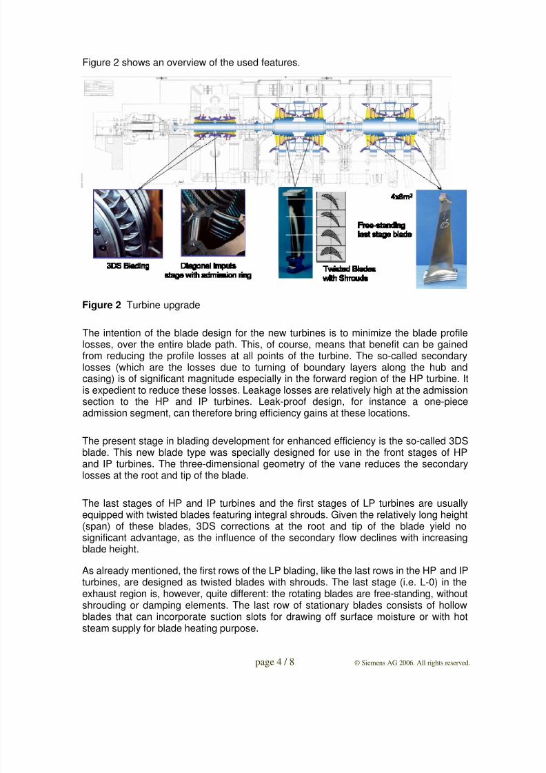
Figure 2 shows an overview of the used features.
Figure 2 Turbine upgrade
The intention of the blade design for the new turbines is to minimize the blade profilelosses, over the entire blade path. This, of course, means that benefit can be gainedfrom reducing the profile losses at all points of the turbine. The so-called secondarylosses (which are the losses due to turning of boundary layers along the hub andcasing) is of significant magnitude especially in the forward region of the HP turbine. Itis expedient to reduce these losses. Leakage losses are relatively high at the admission
section to the HP and IP turbines. Leak-proof design, for instance a one-pieceadmission segment, can therefore bring efficiency gains at these locations.
The present stage in blading development for enhanced efficiency is the so-called 3DSblade. This new blade type was specially designed for use in the front stages of HPand IP turbines. The three-dimensional geometry of the vane reduces the secondarylosses at the root and tip of the blade.
The last stages of HP and IP turbines and the first stages of LP turbines are usuallyequipped with twisted blades featuring integral shrouds. Given the relatively long height(span) of these blades, 3DS corrections at the root and tip of the blade yield no
significant advantage, as the influence of the secondary flow declines with increasingblade height.
As already mentioned, the first rows of the LP blading, like the last rows in the HP and IPturbines, are designed as twisted blades with shrouds. The last stage (i.e. L-0) in theexhaust region is, however, quite different: the rotating blades are free-standing, withoutshrouding or damping elements. The last row of stationary blades consists of hollowblades that can incorporate suction slots for drawing off surface moisture or with hotsteam supply for blade heating purpose.
8/9/2019 4 Turbine and Condenser Modernization
http://slidepdf.com/reader/full/4-turbine-and-condenser-modernization 5/8
page 5 / 8 © Siemens AG 2006. All rights reserved.
Drains are provided on the circumference of the inner casing for the last stage of the LPturbine . One highly effective way of avoiding droplet impact erosion at the last stage isto use slotted hollow blades for the last stationary blade row. The water film on the bladesurface can then be drawn off through the slots.
2.3 New condenser design
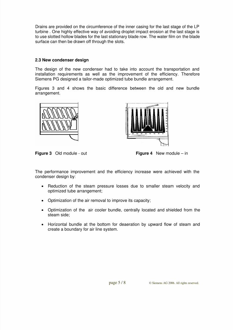
The design of the new condenser had to take into account the transportation andinstallation requirements as well as the improvement of the efficiency. ThereforeSiemens PG designed a tailor-made optimized tube bundle arrangement.
Figures 3 and 4 shows the basic difference between the old and new bundlearrangement.
Figure 3 Old module - out Figure 4 New module – in
The performance improvement and the efficiency increase were achieved with thecondenser design by:
• Reduction of the steam pressure losses due to smaller steam velocity andoptimized tube arrangement;
• Optimization of the air removal to improve its capacity;
• Optimization of the air cooler bundle, centrally located and shielded from thesteam side;
• Horizontal bundle at the bottom for deaeration by upward flow of steam and
create a boundary for air line system.
8/9/2019 4 Turbine and Condenser Modernization
http://slidepdf.com/reader/full/4-turbine-and-condenser-modernization 6/8
page 6 / 8 © Siemens AG 2006. All rights reserved.
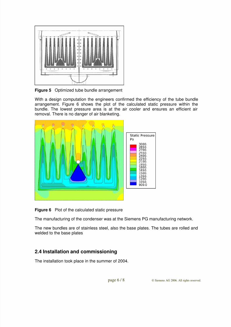
Figure 5 Optimized tube bundle arrangement
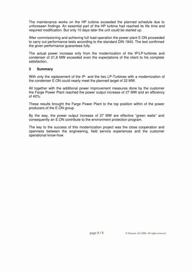
With a design computation the engineers confirmed the efficiency of the tube bundlearrangement. Figure 6 shows the plot of the calculated static pressure within thebundle. The lowest pressure area is at the air cooler and ensures an efficient air
removal. There is no danger of air blanketing.
Figure 6 Plot of the calculated static pressure
The manufacturing of the condenser was at the Siemens PG manufacturing network.
The new bundles are of stainless steel, also the base plates. The tubes are rolled andwelded to the base plates
2.4 Installation and commissioning
The installation took place in the summer of 2004.

8/9/2019 4 Turbine and Condenser Modernization
http://slidepdf.com/reader/full/4-turbine-and-condenser-modernization 7/8
page 7 / 8 © Siemens AG 2006. All rights reserved.
The plant was shut down on 15. August 2004. After 5 days of cooling down the unit,the works started.
The condenser modules were delivered to site before the outage. The despatch of theturbines was handled on time due to the relatively short distance from the factory inMuelheim to the Plant in Bremen.
Of special significance was the exchange of the complete condenser module boxes.The old boxes, installed beneath the turbines, were cut, pulled out through an openedwall in the turbine hall and replaced by new modules.
Figure 7 Pulling out the old condenser module from the turbine hall
Figure 8 Pushing the new condenser module into the turbine hall
At the end of September the modernization scope was finished as planed.
8/9/2019 4 Turbine and Condenser Modernization
http://slidepdf.com/reader/full/4-turbine-and-condenser-modernization 8/8
page 8 / 8 © Siemens AG 2006. All rights reserved.
The maintenance works on the HP turbine exceeded the planned schedule due tounforeseen findings. An essential part of the HP turbine had reached its life time andrequired modification. But only 10 days later the unit could be started up.
After commissioning and achieving full load operation the power plant E.ON proceededto carry out performance tests according to the standard DIN 1943. The test confirmed
the given performance guarantees fully.
The actual power increase only from the modernization of the IP/LP-turbines andcondenser of 21,6 MW exceeded even the expectations of the client to his completesatisfaction.
3 Summary
With only the replacement of the IP- and the two LP-Turbines with a modernization ofthe condenser E.ON could nearly meet the planned target of 22 MW.
All together with the additional power improvement measures done by the customerthe Farge Power Plant reached the power output increase of 27 MW and an efficiency
of 42%.
These results brought the Farge Power Plant to the top position within of the powerproducers of the E.ON group.
By the way, the power output increase of 27 MW are effective “green watts” andconsequently an E.ON contribute to the environment protection program.
The key to the success of this modernization project was the close cooperation andopenness between the engineering, field service experiences and the customeroperational know-how.