4® Spinal System...4 II. Indications and Contraindications S4® Spinal System Surgical Technique...
40
S 4® Spinal System Surgical Technique Aesculap Spine
Transcript of 4® Spinal System...4 II. Indications and Contraindications S4® Spinal System Surgical Technique...

S4® Spinal SystemSurgical Technique
Aesculap Spine
2
S4® Spinal SystemSurgical Technique
I. System Overview . . . . . . . . . . . . . . . . . . . . . . . . . . . . . . . . . . . . . . . . . . . . . . . . . . . . . . . . . 3
II. Indications and Contraindications . . . . . . . . . . . . . . . . . . . . . . . . . . . . . . . . . . . . . . . . . . . . 4
III. Warnings and Precautions . . . . . . . . . . . . . . . . . . . . . . . . . . . . . . . . . . . . . . . . . . . . . . . . . . 5
IV. Surgical Technique . . . . . . . . . . . . . . . . . . . . . . . . . . . . . . . . . . . . . . . . . . . . . . . . . . . . . . . . 6
1. Pedicle Preparation . . . . . . . . . . . . . . . . . . . . . . . . . . . . . . . . . . . . . . . . . . . . . . . . . . . 6
2. Tapping (Optional) . . . . . . . . . . . . . . . . . . . . . . . . . . . . . . . . . . . . . . . . . . . . . . . . . . . . 7
3. Screw Application . . . . . . . . . . . . . . . . . . . . . . . . . . . . . . . . . . . . . . . . . . . . . . . . . . . . 8
4. Rod Placement . . . . . . . . . . . . . . . . . . . . . . . . . . . . . . . . . . . . . . . . . . . . . . . . . . . . . .10
5. Rod Reduction (Optional) . . . . . . . . . . . . . . . . . . . . . . . . . . . . . . . . . . . . . . . . . . . . .11
6. Set Screw Application . . . . . . . . . . . . . . . . . . . . . . . . . . . . . . . . . . . . . . . . . . . . . . . .12
7. Compression Maneuver . . . . . . . . . . . . . . . . . . . . . . . . . . . . . . . . . . . . . . . . . . . . . . .13
8. Distraction Maneuver . . . . . . . . . . . . . . . . . . . . . . . . . . . . . . . . . . . . . . . . . . . . . . . .13
9. Derotation Maneuver . . . . . . . . . . . . . . . . . . . . . . . . . . . . . . . . . . . . . . . . . . . . . . . . .14
10. Final Tightening . . . . . . . . . . . . . . . . . . . . . . . . . . . . . . . . . . . . . . . . . . . . . . . . . . . . .15
11. Tap Removal . . . . . . . . . . . . . . . . . . . . . . . . . . . . . . . . . . . . . . . . . . . . . . . . . . . . . . . .16
V. ADDENDUM: Cross Connector Application . . . . . . . . . . . . . . . . . . . . . . . . . . . . . . . . . . . .17
VI. ADDENDUM: Rod-to-Rod Connector Application . . . . . . . . . . . . . . . . . . . . . . . . . . . . . . .17
1. Axial Rod-to-Rod Connector . . . . . . . . . . . . . . . . . . . . . . . . . . . . . . . . . . . . . . . . . . .18
2. Domino Rod-to-Rod . . . . . . . . . . . . . . . . . . . . . . . . . . . . . . . . . . . . . . . . . . . . . . . . . .19
3. Pelvic Screw & Lateral Offset . . . . . . . . . . . . . . . . . . . . . . . . . . . . . . . . . . . . . . . . . .20
VII. ADDENDUM: Hook Application . . . . . . . . . . . . . . . . . . . . . . . . . . . . . . . . . . . . . . . . . . . . .25
1. Pedicle Hook Application . . . . . . . . . . . . . . . . . . . . . . . . . . . . . . . . . . . . . . . . . . . . . .25
2. Lamina Hook Application . . . . . . . . . . . . . . . . . . . . . . . . . . . . . . . . . . . . . . . . . . . . .27
3. Thoracic Hook Application . . . . . . . . . . . . . . . . . . . . . . . . . . . . . . . . . . . . . . . . . . . . .27
VIII. Implant Overview . . . . . . . . . . . . . . . . . . . . . . . . . . . . . . . . . . . . . . . . . . . . . . . . . . . . . . . . .28
IX. Instrument Overview . . . . . . . . . . . . . . . . . . . . . . . . . . . . . . . . . . . . . . . . . . . . . . . . . . . . . .31
2
S4® Spinal SystemSurgical Technique
Table of Contents
33
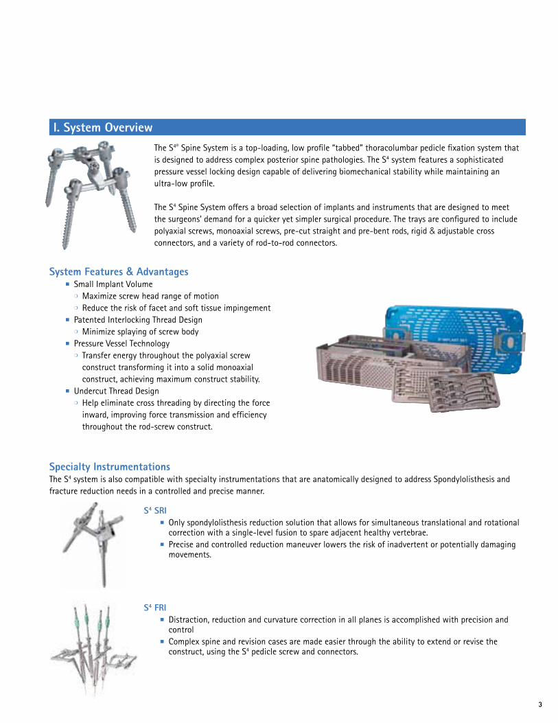
The S4® Spine System is a top-loading, low profile “tabbed” thoracolumbar pedicle fixation system that is designed to address complex posterior spine pathologies. The S4 system features a sophisticated pressure vessel locking design capable of delivering biomechanical stability while maintaining an ultra-low profile.
The S4 Spine System offers a broad selection of implants and instruments that are designed to meet the surgeons’ demand for a quicker yet simpler surgical procedure. The trays are configured to include polyaxial screws, monoaxial screws, pre-cut straight and pre-bent rods, rigid & adjustable cross connectors, and a variety of rod-to-rod connectors.
Specialty InstrumentationsThe S4 system is also compatible with specialty instrumentations that are anatomically designed to address Spondylolisthesis and fracture reduction needs in a controlled and precise manner.
I. System Overview
System Features & Advantages ■ Small Implant Volume ❍ Maximize screw head range of motion ❍ Reduce the risk of facet and soft tissue impingement ■ Patented Interlocking Thread Design ❍ Minimize splaying of screw body ■ Pressure Vessel Technology ❍ Transfer energy throughout the polyaxial screw
construct transforming it into a solid monoaxial construct, achieving maximum construct stability.
■ Undercut Thread Design ❍ Help eliminate cross threading by directing the force
inward, improving force transmission and efficiency throughout the rod-screw construct.
S4 SRI ■ Only spondylolisthesis reduction solution that allows for simultaneous translational and rotational
correction with a single-level fusion to spare adjacent healthy vertebrae. ■ Precise and controlled reduction maneuver lowers the risk of inadvertent or potentially damaging
movements.
S4 FRI ■ Distraction, reduction and curvature correction in all planes is accomplished with precision and
control ■ Complex spine and revision cases are made easier through the ability to extend or revise the
construct, using the S4 pedicle screw and connectors.

4
II. Indications and Contraindications
S4® Spinal SystemSurgical Technique
The S4 Spinal System is intended for anterior/anterolateral and posterior, non-cervical pedicle and non-pedicle fixation. Fixation is limited to skeletally mature patients and is intended to be used as an adjunct to fusion using autograft or allograft. The device is indicated for treatment of the following acute and chronic instabilities or deformities:1. Degenerative disc disease (defined as discogenic back
pain with degeneration of the disc confirmed by history and radiographic studies),
2. Spondylolisthesis,3. Trauma (i.e., fracture or dislocation),4. Spinal Stenosis,5. Deformities or Curvatures (i.e., scoliosis, kyphosis, and/or
lordosis),6. Tumor,7. Pseudoarthrosis, and8. Failed previous fusion
ContraindicationsContraindications of the S4 Spinal System are similar to other commercially available posterior spinal fixation systems of similar design and material. Contraindications include, but are not limited to, the following: 1. Use in the Cervical Spine 2. Active systemic or local infection 3. Obesity 4. Pregnancy 5. Mental illness 6. Severe osteoporosis or osteopenia 7. Metal sensitivity/ allergies to the implant material 8. Alcohol or drug abuse 9. Patients unwilling or unable to follow postoperative
instructions 10. Neuromuscular diseases/ disorders 11. Soft tissue deficit not allowing wound closure 12. Any medical or physical condition that would preclude
the potential benefit of spinal implant surgery 13. Congenital abnormalities, tumors or other conditions
that would prevent secure component fixation that has the potential to decrease the useful life of the device.
14. Any medical or mental condition which would exclude the patient or put the patient at high risk from surgery of this severity.
15. For pedicle screw cases, inadequate pedicles of the fifth lumbar (L5) vertebrae.
Complications and possible adverse effectsPrior to surgery, patients should be made aware of the following possible adverse effects in addition to the potential for additional surgery to correct these effects: 1. Loosening, disassembly, bending or breakage of
components 2. Tissue sensitivity to implant material 3. Potential for skin breakdown and/ or wound
complications 4. Non-union or delayed union 5. Infection 6. Nerve damage, including loss of neurologic function,
dural tears, paralysis, paresthesia, and cerebral spinal fluid leakage
7. Fracture of vertebrae 8. Infection 9. Loss of fixation 10. Vascular or visceral injury 11. Chance of normal spinal curvature 12. Gastrointestinal, urological and/ or reproductive system
compromise 13. Pain or discomfort 14. Bursitis 15. Decrease in bone density due to stress shielding 16. Loss of bone or fracture of bone above or below the
level of surgery 17. Bone graft donor site pain, fracture, and/ or delayed
wound healing 18. Restriction of activities 19. Lack of effective treatment of symptoms for which the
surgery was intended 20. Death
5
III. Warnings and Precautions
Cautions/Precautions & Warnings■ No component of the S4® Spinal System should be reused
after being removed from the body. An implant should never be re-sterilized after contact with body tissues or body fluids.
■ Damage to the implant can occur if the clamping screw is overtightened. Do not tighten the clamping screw without using the countering instrument or screw head expansion can occur.
■ Damage to the implant can occur when implant set screw is over torqued.
■ Damage to the implant can occur if the repositioning instruments are positioned too high in relation to the implant. Always apply repositioning instruments (e.g. distraction and compression forceps) below the rod at the implant.
■ During derotation, screw head expansion may occur if derotation sleeves are not used.
■ The implant can be damaged by spondylolisthesis repositioning through the clamping screw. Always use the rod persuader for spondylolisthesis repositioning.
■ This system should only be used with instrumentation specifically designed for this system and the surgeon should be familiar with the surgical technique.
PRECAUTION The S4 system has not been evaluated for safety and
compatibility in the MR environment. The S4 system has not been tested for heating or migration in the MR environment.
PRECAUTION Components of competitive spinal fixation systems should
not be used with components of the S4 Spinal System. Components of dissimilar material should not be used together due to the potential for accelerating the corrosion process by mixing of dissimilar materials.
PRECAUTION The implantation of pedicle screw spinal systems should
be performed only by experienced spinal surgeons with specific training in the use of this pedicle screw spinal system because this is a technically demanding procedure presenting a risk of serious injury to the patient.
PRECAUTION Based on the fatigue testing results, the physician/surgeon
should consider the levels of implantation, patient weight, patient activity level, other patient conditions, etc. which may affect the performance of the system.
WARNING The safety and effectiveness of pedicle screw spinal systems
have been established only for spinal conditions with significant mechanical instability or deformity requiring fusion with instrumentation. These conditions are significant mechanical instability or deformity of the thoracic, lumbar, and sacral spine secondary to degenerative spondylolisthesis with objective evidence of neurological impairment, fracture, dislocation, scoliosis, kyphosis, spinal tumor, and failed previous fusion (pseudarthrosis). The safety and effectiveness of these devices for any other conditions are unknown.
WARNING The S4 Spinal System is not intended to be used without
bone graft which is required to provide additional spinal support. Use of this product without bone graft or in cases that develop into a non-union will eventually be unsuccessful. A successful result is not always achieved in every surgical case. No posterior spinal fixation system can withstand body loads without the support of bone. In the event that bone is not provided to facilitate fusion, bending, loosening, disassembling, and/ or breakage of the implant will eventually occur.

6
S4® Spinal SystemSurgical Technique
IV. Surgical Technique
Fig. 1
■ Use the pedicle probe to open the pedicle canal. (Fig. 2)
❍ The pedicle probes are available in straight or curved blunt-tip (FW188R or FW189R) and straight or curved Lenke (FW248R or FW249R).
❍ The probes have ruled markings to deter-mine the depth measurement in the pedicle canal.
1. Pedicle Preparation ■ Determine pedicle entry point and perforate
the cortex using the bone awl (FW190R). (Fig. 1)
Fig. 2

7
Fig. 3
Fig. 4
2. Tapping (Optional)Although the S4® Spine System screws are self-tapping, screw taps are available in all diameters, if desired. ■ To tap, attach the ratchet handle or the
T-handle (ME175R or FW167R) to the appropriate tap based on the screw diameter. Refer to page 32 for a complete list of taps sizes. (Fig. 4)
■ Utilize the straight or curved pedicle sounder (FW146R or FW147R) to confirm the patency of the pedicle and vertebral body cortex. (Fig. 3)

8
S4® Spinal SystemSurgical Technique
Fig. 5
■ Thread the screw into the prepared pedicle (Fig. 6) and release the screwdriver from the head of the screw.
3. Screw Application Color-coded polyaxial and monoaxial screws are available in various lengths and diameters. Refer to pages 28-30 for a complete list of implant sizes.
■ Select the appropriate screwdriver based on the screw style.
❍ For polyaxial screws either use the self-retaining polyaxial screwdriver (FW173R) or the rigid fixation screw driver (FW156R).
❍ For monoaxial screws, use the rounded tip monoaxial screw driver (FW176R).
a) Polyaxial Screw Application ■ Attach and fully engage the hexagonal tip of the
polyaxial screwdriver into the head of the screw. ■ If using the rigid fixation screwdriver, engage
the hexagonal tip and then rotate the twist knob in a clockwise fashion while holding the bone screw to lock the threaded end of the screwdriver into the screw head as shown in (Fig. 5).
Fig. 6
Note: If the polyaxicity of the screw remains, the screw is not fully engaged.
Caution: Ensure that the screwdriver is fully engaged and threaded onto the screw.
9
Fig. 7
Fig. 8
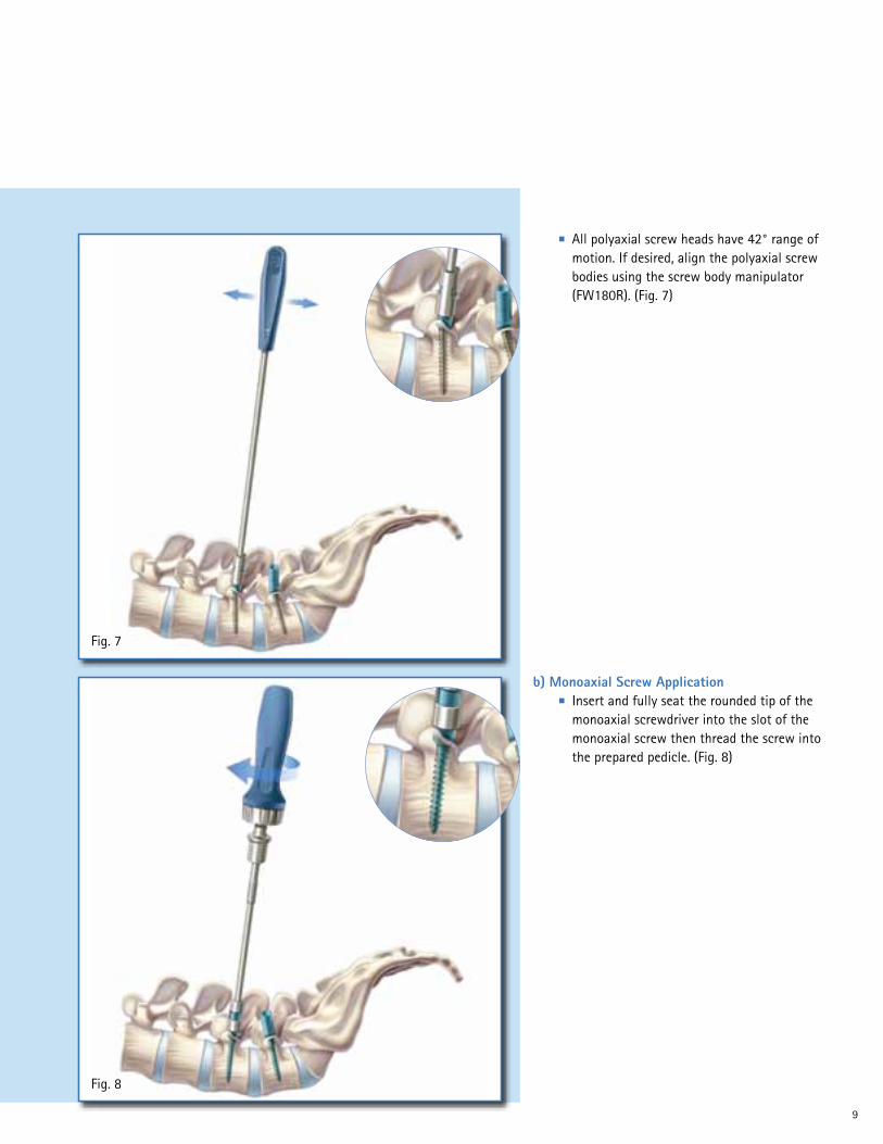
b) Monoaxial Screw Application ■ Insert and fully seat the rounded tip of the
monoaxial screwdriver into the slot of the monoaxial screw then thread the screw into the prepared pedicle. (Fig. 8)
■ All polyaxial screw heads have 42° range of motion. If desired, align the polyaxial screw bodies using the screw body manipulator (FW180R). (Fig. 7)

10
S4® Spinal SystemSurgical Technique
Fig. 9
Both pre-bent and straight rods are available. ■ All rods may be contoured using the French
rod bender (FW024R). ■ To contour the rod, place rod on the bender
and squeeze the handle until the desired curvature is achieved. (Fig. 10)
4. Rod Placement ■ Use the flexible rod trails (FW185R) as a
guide for rod bending and measuring correct rod length. (Fig. 9)
Fig. 10

11
Fig. 11
Fig. 12
5. Rod Reduction (Optional)The rod persuader (FW208R) can be used to help seat the rod fully into the saddle of the screw in multilevel cases. Using the rod persuader also simplifies set screw placement. ■ Place the rod persuader on the screw head so
that rod is fully engaged. ■ Squeeze the handle to seat the rod into the
head of the screw. The ratchet will hold the rod persuader in the reduced position while the set screw is applied. (Fig. 12)
■ Use the rod holding forceps (FW012R) to assist with rod placement or rod manipulation. (Fig. 11)
12
S4® Spinal SystemSurgical Technique
Fig. 13
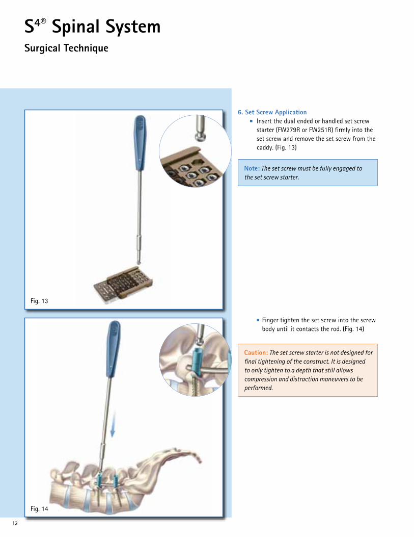
■ Finger tighten the set screw into the screw body until it contacts the rod. (Fig. 14)
6. Set Screw Application ■ Insert the dual ended or handled set screw
starter (FW279R or FW251R) firmly into the set screw and remove the set screw from the caddy. (Fig. 13)
Fig. 14
Note: The set screw must be fully engaged to the set screw starter.
Caution: The set screw starter is not designed for final tightening of the construct. It is designed to only tighten to a depth that still allows compression and distraction maneuvers to be performed.

13
Fig. 15
Fig. 16
8. Distraction Maneuver Use the distraction forceps (FW281R) to distract the construct. (Fig. 16) ■ Fully tighten one set screw to create a fixed
point for distraction (as described in section 10 page 15).
■ Fully seat the counter torque L-handle (FW178R) or the derotation sleeves on the unlocked screw body and perform the distraction maneuver
■ Once the desired distraction is achieved, final tighten the remaining set screw.
7. Compression Maneuver Use the compression forceps (FW282R) to compress the construct. (Fig. 15) ■ Fully tighten one set screw to create a fixed
point for compression (as described in section 10 page 15).
■ Fully seat the counter torque L-handle (FW178R) or the derotation sleeves on the unlocked screw body and perform the compression maneuver
■ Once the desired compression is achieved, final tighten the remaining set screw.

14
S4® Spinal SystemSurgical Technique
Fig. 17
9. Derotation Maneuver Use the derotation sleeves (FW183R) and the counter torque L-handle to rotate the rod. (Fig. 17) ■ Place the derotation sleeves over the pedicle
screws that contain the rod to be rotated ■ Connect the counter torque L-handle to one
of the derotation sleeves to perform the rotation maneuver.
■ Once the desired rotation is achieved, fully tighten the set screws (as described in section 10, page 15).
Caution: The derotation sleeves should be used during rotation maneuvers to prevent splaying of the implant head.
15
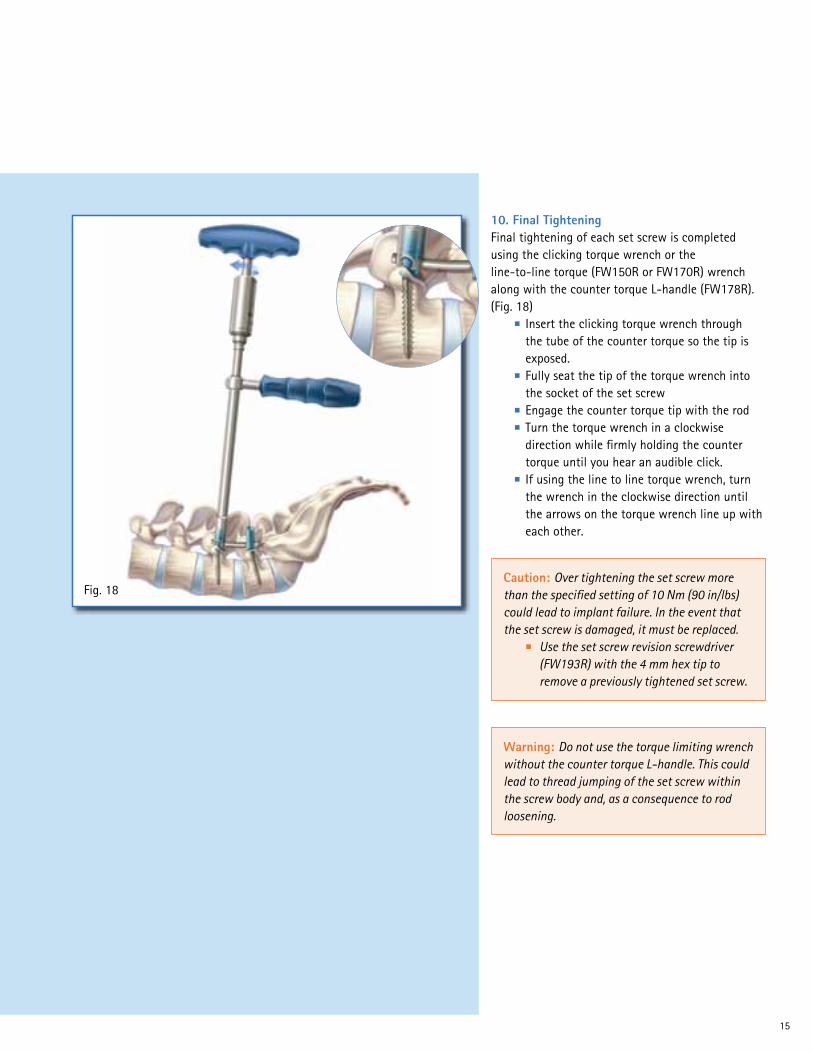
Fig. 18
10. Final TighteningFinal tightening of each set screw is completed using the clicking torque wrench or the line-to-line torque (FW150R or FW170R) wrench along with the counter torque L-handle (FW178R). (Fig. 18) ■ Insert the clicking torque wrench through
the tube of the counter torque so the tip is exposed.
■ Fully seat the tip of the torque wrench into the socket of the set screw
■ Engage the counter torque tip with the rod ■ Turn the torque wrench in a clockwise
direction while firmly holding the counter torque until you hear an audible click.
■ If using the line to line torque wrench, turn the wrench in the clockwise direction until the arrows on the torque wrench line up with each other.
Caution: Over tightening the set screw more than the specified setting of 10 Nm (90 in/lbs) could lead to implant failure. In the event that the set screw is damaged, it must be replaced. ■ Use the set screw revision screwdriver
(FW193R) with the 4 mm hex tip to remove a previously tightened set screw.
Warning: Do not use the torque limiting wrench without the counter torque L-handle. This could lead to thread jumping of the set screw within the screw body and, as a consequence to rod loosening.

16
S4® Spinal SystemSurgical Technique
Fig. 19
11. Tab Removal ■ Break off the extended tabs with the tab
breaker (FW179R). (Fig. 19)
Note: Verify that all screws are fully tightened before breaking off the extended tabs. If a tab is prematurely broken off, use the rod persuader to help seat the rod fully into the saddle of the screw, which should simplify set screw placement.
17
Fig. 20
Fig. 21
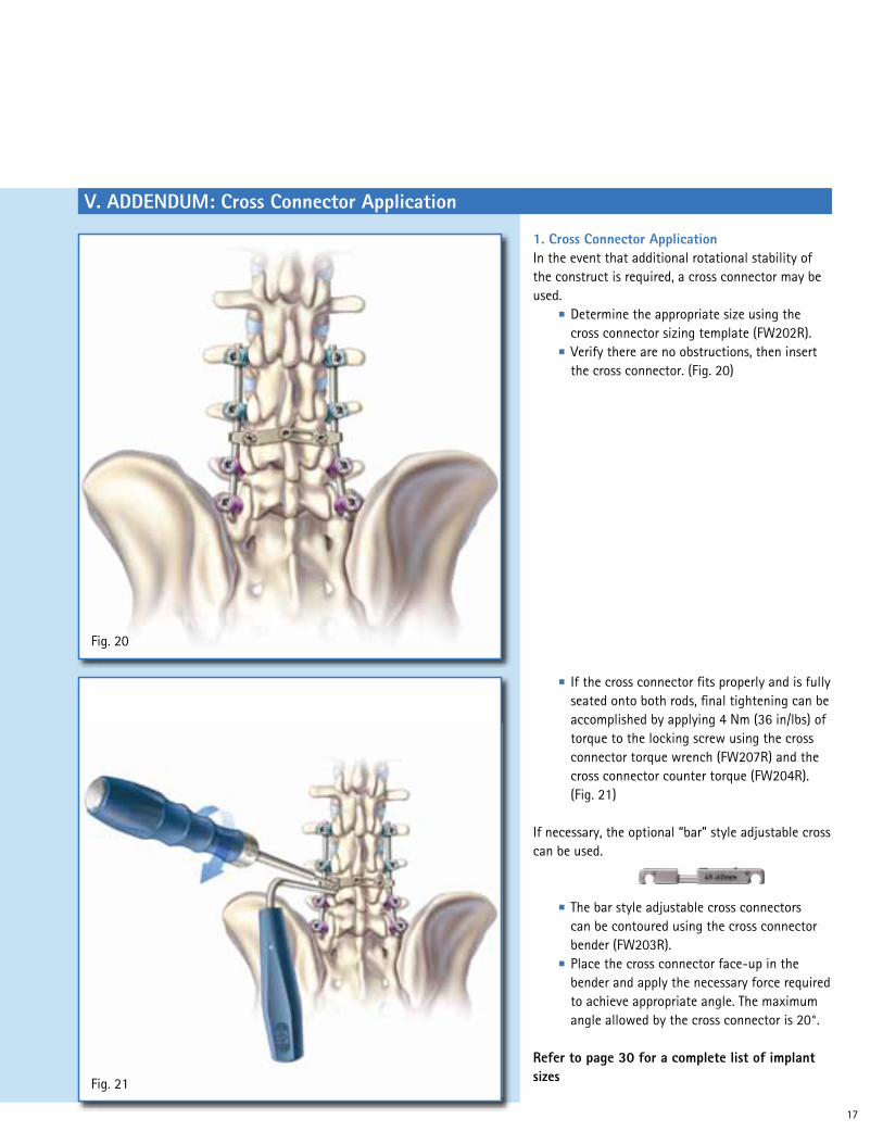
■ If the cross connector fits properly and is fully seated onto both rods, final tightening can be accomplished by applying 4 Nm (36 in/lbs) of torque to the locking screw using the cross connector torque wrench (FW207R) and the cross connector counter torque (FW204R). (Fig. 21)
If necessary, the optional “bar” style adjustable cross can be used.
■ The bar style adjustable cross connectors can be contoured using the cross connector bender (FW203R).
■ Place the cross connector face-up in the bender and apply the necessary force required to achieve appropriate angle. The maximum angle allowed by the cross connector is 20°.
Refer to page 30 for a complete list of implant sizes
1. Cross Connector ApplicationIn the event that additional rotational stability of the construct is required, a cross connector may be used. ■ Determine the appropriate size using the
cross connector sizing template (FW202R). ■ Verify there are no obstructions, then insert
the cross connector. (Fig. 20)
V. ADDENDUM: Cross Connector Application

18
S4® Spinal SystemSurgical Technique
VI. ADDENDUM: Rod-to-Rod Connector Application
Fig. 22
■ Final tighten by applying 4 Nm (36 in/lbs) of torque using the torque wrench screwdriver (FW207R) and the rod-to-rod connector counter torque device (FW495R). (Fig. 23)
A rod-to-rod connector may be used to extend an existing construct in the event of a revision surgery or for a new multilevel construct or to connect to an offset screw.
1. Axial Rod-to-Rod Connector Application ■ To place the axial rod-to-rod connector, first
determine required length (short or long). ■ Use the rod-to-rod connector inserter
(FW493R) to grab the connector and fully seat the rods inside the connector and confirm adequate rod placement using the provided window on the connector. (Fig. 22)
Fig. 23
19
Fig. 24
Fig. 25
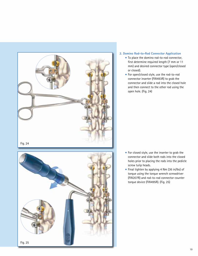
■ For closed style, use the inserter to grab the connector and slide both rods into the closed holes prior to placing the rods into the pedicle screw tulip heads.
■ Final tighten by applying 4 Nm (36 in/lbs) of torque using the torque wrench screwdriver (FW207R) and rod-to-rod connector counter torque device (FW495R). (Fig. 25)
2. Domino Rod-to-Rod Connector Application ■ To place the domino rod-to-rod connector,
first determine required length (7 mm or 11 mm) and desired connector type (open/closed or closed).
■ For open/closed style, use the rod-to-rod connector inserter (FW493R) to grab the connector and slide a rod into the closed hole and then connect to the other rod using the open hole. (Fig. 24)

20
S4® Spinal SystemSurgical Technique
Fig. 26
■ Perforate the ilium using a straight or curved extended length bone probe (FW476R or FW477R) or straight or curved extended length thoracic probe (FW474R or FW475R). (Fig. 27)
3. Pelvic Screw & Lateral Offset Connector Application The posterior of the iliac crest needs to be exposed for pelvic screw placement. Approximately 1.0 to 2.0 centimeters up from the tip of the spine is an ideal starting point. ■ Use a rongeur to make a notch in the crest
of sufficient length and depth for the head of the iliac screw. (Fig. 26)
Fig. 27

21
Fig. 28
Fig. 29
■ Tap canal and identify depth with the desired 7.0 mm extended screw tap (FW497R) or 8.0 mm extended screw tap (FW498R), and choose screw length. (Fig. 29)
■ Utilize the straight or curved (FW146R or FW147R) pedicle sounder to confirm the patency of the Ilium canal. Stop every few centimeters during perforation to check integrity of the canal. (Fig. 28)

22
S4® Spinal SystemSurgical Technique
Fig. 30
■ Use the rod-to-rod connector inserter (FW493R) to grab the lateral offset connector and attach it to the rod from the main construct. (Fig. 31)
■ Attach desired handle to polyaxial screwdriver (FW277R) and thread the screw into the ilium. (Fig. 30)
■ Determine offset distance between the pelvic screw and the rod from the main construct and choose desired lateral offset connector type (open/closed or closed).
Fig. 31
23
Fig. 32
Fig. 33
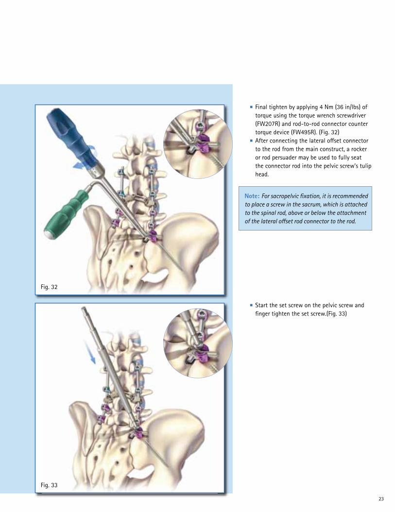
■ Start the set screw on the pelvic screw and finger tighten the set screw.(Fig. 33)
■ Final tighten by applying 4 Nm (36 in/lbs) of torque using the torque wrench screwdriver (FW207R) and rod-to-rod connector counter torque device (FW495R). (Fig. 32)
■ After connecting the lateral offset connector to the rod from the main construct, a rocker or rod persuader may be used to fully seat the connector rod into the pelvic screw’s tulip head.
Note: For sacropelvic fixation, it is recommended to place a screw in the sacrum, which is attached to the spinal rod, above or below the attachment of the lateral offset rod connector to the rod.

24
S4® Spinal SystemSurgical Technique
Fig. 34
■ Final tighten the set screw by using the clicking torque wrench or the line to line torque wrench along with the counter torque L-handle (FW170R) (as described in section 10). (Fig. 34)
Note: For removal of rod-to-rod connector, use connector revision screwdriver (FW491R). To remove pedicle screw, first use set screw revision screwdriver (FW193R) to disengage set screw and use screwdriver with shank tip (FW174R) to remove the polyaxial screw.

25
Fig. 36
Fig. 37
■ Prepare the bed for pedicle hook insertion with the pedicle preparator (FW251R). (Fig. 37)
1. Pedicle Hook Application ■ Resect the tip of the inferior articular process
using an osteotome. (Fig. 36)
VII. ADDENDUM: Hook Application
Note: If the facet is not resected enough, the pedicle preparator blade will not allow proper preparation of the pedicle. Further resection of the facet is then recommended.

26
S4® Spinal SystemSurgical Technique
Fig. 38
■ Show the pedicle hook fully seated. (Fig. 39)
■ Attach the hook to the facet joint using the hook holder (FW211R) supported by the hook pusher (FW212R). The hook can be impacted by the hook pusher. (Fig. 38)
Fig. 39

27
Fig. 40
Fig. 41
3. Thoracic Hook Application ■ The smooth, slim design of the thoracic
hook is adapted to the shape of the thoracic lamina.
■ Prepare and place the thoracic hooks in the same way as the lamina hooks.
■ (Fig. 41)
2. Lamina Hook Application ■ Prepare a flat bed for the lamina hook with
the lamina preparator (FW152R). ■ Maintain the hook in a horizontal position
using the hook holder (FW211R) and carefully rotate around the edge of the lamina in a vertical position supported by the hook pusher (FW212R).
■ (Fig. 40)
Note: Tightening of the hooks to the rod is conducted in the same way as the pedicle screws as described in sections 6, 10 & 11).

28
S4® Spinal SystemSurgical Technique
VIII. Implant Overview
Item No. Diameter LengthSW701T 4.5 mm 25 mmSW702T 4.5 mm 30 mmSW703T 4.5 mm 35 mmSW704T 4.5 mm 40 mmSW706T 4.5 mm 45 mmSW707T 4.5 mm 50 mm
SW711T 5.0 mm 25 mmSW712T 5.0 mm 30 mmSW713T 5.0 mm 35 mmSW714T 5.0 mm 40 mmSW716T 5.0 mm 45 mmSW717T 5.0 mm 50 mm
SW721T 6.0 mm 25 mmSW722T 6.0 mm 30 mmSW723T 6.0 mm 35 mmSW724T 6.0 mm 40 mmSW726T 6.0 mm 45 mmSW727T 6.0 mm 50 mmSW728T 6.0 mm 55 mmSW729T 6.0 mm 60 mm
Item No. Diameter LengthSW731T 7.0 mm 25 mmSW732T 7.0 mm 30 mmSW733T 7.0 mm 35 mmSW734T 7.0 mm 40 mmSW736T 7.0 mm 45 mmSW737T 7.0 mm 50 mmSW738T 7.0 mm 55 mmSW739T 7.0 mm 60 mm
SW742T 8.0 mm 30 mmSW743T 8.0 mm 35 mmSW744T 8.0 mm 40 mmSW746T 8.0 mm 45 mmSW747T 8.0 mm 50 mmSW748T 8.0 mm 55 mmSW749T 8.0 mm 60 mm
Item No. Diameter LengthSW751T 4.5 mm 25 mmSW752T 4.5 mm 30 mmSW753T 4.5 mm 35 mmSW754T 4.5 mm 40 mmSW756T 4.5 mm 45 mmSW757T 4.5 mm 50 mm
SW761T 5.0 mm 25 mmSW762T 5.0 mm 30 mmSW763T 5.0 mm 35 mmSW764T 5.0 mm 40 mmSW766T 5.0 mm 45 mmSW767T 5.0 mm 50 mm
SW771T 6.0 mm 25 mmSW772T 6.0 mm 30 mmSW773T 6.0 mm 35 mmSW774T 6.0 mm 40 mmSW776T 6.0 mm 45 mmSW777T 6.0 mm 50 mmSW778T 6.0 mm 55 mmSW779T 6.0 mm 60 mm
Item No. Diameter LengthSW781T 7.0 mm 25 mmSW782T 7.0 mm 30 mmSW783T 7.0 mm 35 mmSW784T 7.0 mm 40 mmSW786T 7.0 mm 45 mmSW787T 7.0 mm 50 mmSW788T 7.0 mm 55 mmSW789T 7.0 mm 60 mm
SW792T 8.0 mm 30 mmSW793T 8.0 mm 35 mmSW794T 8.0 mm 40 mmSW796T 8.0 mm 45 mmSW797T 8.0 mm 50 mmSW798T 8.0 mm 55 mmSW799T 8.0 mm 60 mm
Item No. Diameter LengthSW802T 9.0 mm 30 mmSW803T 9.0 mm 35 mmSW804T 9.0 mm 40 mmSW806T 9.0 mm 45 mmSW807T 9.0 mm 50 mmSW808T 9.0 mm 55 mmSW809T 9.0 mm 60 mm
SW812T 10.0 mm 30 mmSW813T 10.0 mm 35 mmSW814T 10.0 mm 40 mmSW816T 10.0 mm 45 mmSW817T 10.0 mm 50 mmSW818T 10.0 mm 55 mmSW819T 10.0 mm 60 mm
S4 Polyaxial Screws
S4® Monoaxial Screws

29
S4® Lamina Hooks (Gold)Item No. Size TypeSW826T 6 mm Left SW827T 6 mm RightSW827T 10 mm Left SW828T 10 mm Right
S4 Pedicle Hooks (Silver)Item No. SizeSW831T 6 mmSW832T 10 mm
S4 Thoracic Hooks (Blue)Item No. SizeSW833T 6 mmSW834T 8 mm
S4 Set ScrewItem No. DescriptionSW790T Set Screw
S4 Pre-Bent Rods, 5.5 mmItem No. LengthSW653T 30 mmSW654T 35 mmSW655T 40 mmSW656T 45 mmSW657T 50 mmSW658T 55 mmSW659T 60 mmSW661T 70 mmSW662T 80 mmSW663T 90 mmSW684T 100 mm
S4 Straight Rods, 5.5 mmItem No. LengthSW674T 35 mmSW675T 40 mmSW676T 45 mmSW677T 50 mmSW678T 55 mmSW679T 60 mmSW681T 70 mmSW682T 80 mmSW664T 100 mmSW666T 120 mmSW667T 150 mmSW668T 180 mmSW669T 200 mmSW670T 300 mmSW671T 400 mmSW672T 500 mm

30
S4® Spinal SystemSurgical Technique
Rod-to-rod Connectors Item No. Type LengthSW842T Closed Domino Connector 7 mm
SW844T Closed Domino Connector 11 mm
SW841T Closed/Open Domino Connector 7 mm
SW843T Closed/Open Domino Connector 11 mm
SW838T Axial Connector Short
SW839T Axial Connector Long
SW847T Closed Lateral Offset Connector 20 mm
SW849T Closed Lateral Offset Connector 35 mm
SW872T Closed Lateral Offset Connector 50 mm
SW846T Open Lateral Offset Connector 20 mm
SW848T Open Lateral Offset Connector 35 mm
SW871T Open Lateral Offset Connector 50 mm
S4 Adjustable Cross ConnectorsItem No. LengthSW488T 35-36 mmSW489T 36-38 mmSW494T 38-42 mmSW495T 42-50 mmSW496T 50-60 mmSW497T 60-77 mmSW498T 77-107 mmSW697T 43-49 mmSW698T 49-60 mmSW699T 60-75 mm
S4 Rigid Cross ConnectorsItem No. LengthSW490T 28 mmSW491T 30 mmSW492T 32 mmSW493T 34 mmSW690T 21 mmSW691T 25 mmSW695T 38 mmSW696T 41 mm

31
AwlItem No. Description
FW190R Bone Awl
ProbesItem No. Description
FW188RStraight Pedicle Probe
FW189RCurved Pedicle Probe
FW248RStraight Lenke Probe
FW249RCurved Lenke Probe
SoundersItem No. Description
FW146RStraight Pedicle Sounder
FW147RCurved Pedicle Sounder
Pedicle MarkersItem No. Description
FW191RSingle Band Pedicle Marker
FW192RDual Band Pedicle Marker
IX. Instrument Overview
32
S4® Spinal SystemSurgical Technique
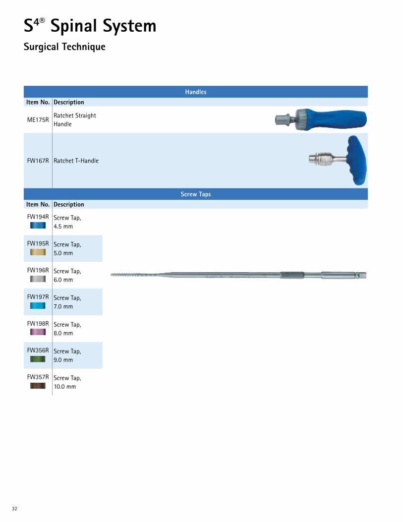
HandlesItem No. Description
ME175RRatchet Straight Handle
FW167R Ratchet T-Handle
Screw TapsItem No. Description
FW194R Screw Tap, 4.5 mm
FW195R Screw Tap, 5.0 mm
FW196R Screw Tap, 6.0 mm
FW197R Screw Tap, 7.0 mm
FW198R Screw Tap, 8.0 mm
FW356R Screw Tap, 9.0 mm
FW357R Screw Tap, 10.0 mm

33
ScrewdriversItem No. Description
FW156RPolyaxial Screws Rigid Fixation Screwdriver
FW173RPolyaxial Screws Retaining Clip Screwdriver
FW176RMonoaxial Screws Screwdriver
FW174RRemoval Screwdriver with Shank Tip
FW193RSet Screw Revision Screwdriver
ManipulatorItem No. Description
FW180RScrew Body Manipulator
Set Screw StartersItem No. Description
FW279RDual Ended Set Screw Starter
FW251RHandled Set Screw Starter
34
S4® Spinal SystemSurgical Technique
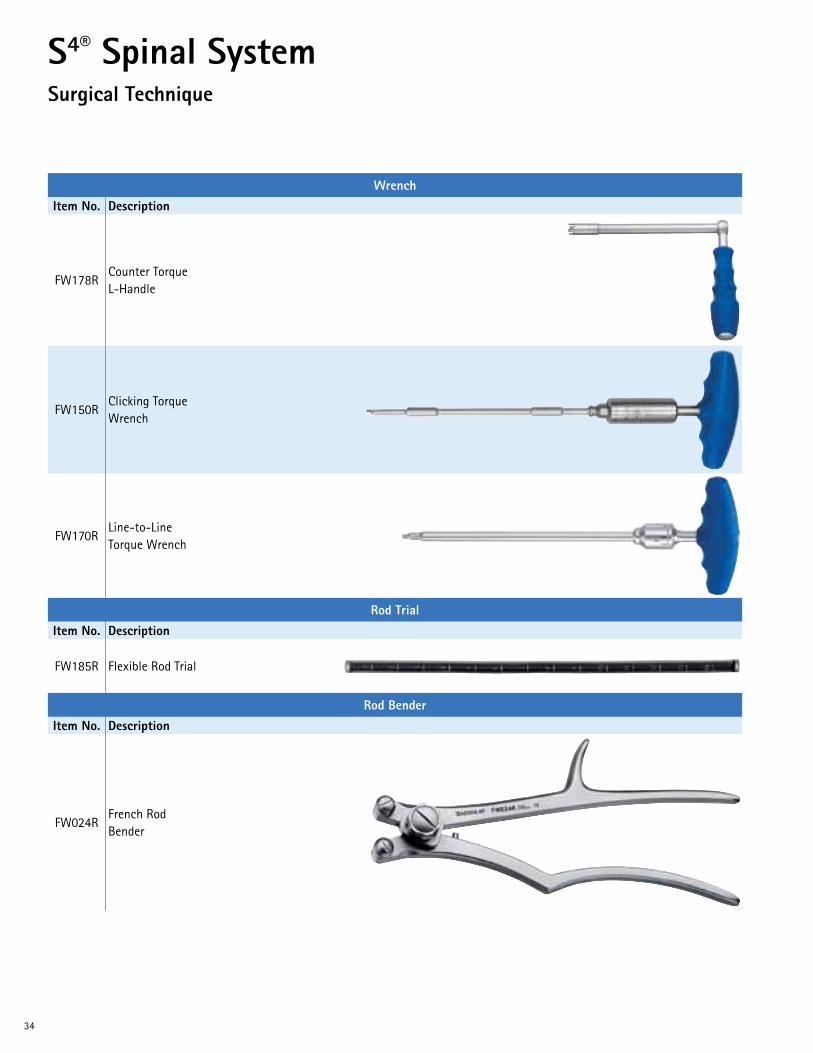
WrenchItem No. Description
FW178RCounter Torque L-Handle
FW150RClicking Torque Wrench
FW170RLine-to-Line Torque Wrench
Rod TrialItem No. Description
FW185R Flexible Rod Trial
Rod BenderItem No. Description
FW024RFrench Rod Bender

35
Rod Holding ForcepsItem No. Description
FW012RRod Holding Forceps
Rod PusherItem No. Description
FW513R Rod Pusher
Rod PersuaderItem No. Description
FW208R Rod Persuader
BendersItem No. Description
FW252RIn-situ Rod Bender, Left
FW253RIn-situ Rod Bender, Right
36
S4® Spinal SystemSurgical Technique
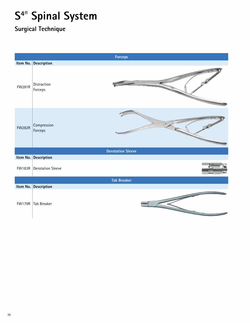
ForcepsItem No. Description
FW281RDistraction Forceps
FW282RCompression Forceps
Derotation SleeveItem No. Description
FW183R Derotation Sleeve
Tab BreakerItem No. Description
FW179R Tab Breaker

37
Connector InstrumentsItem No. Description
FW493RRod-to-Rod Connector Inserter
FW495RRod-to-Rod Connector Counter-torque
FW491RConnector Revision Screwdriver

38
S4® Spinal SystemSurgical Technique
Screw Taps & Bone ProbesItem No. Description
FW497RExtended Length Screw Tap, 7.0 mm
FW498RExtended Length Screw Tap, 8.0 mm
FW474RExtended Length Lenke Probe, Straight
FW475RExtended Length Lenke Probe, Curved
FW476RExtended Length Bone Probe, Straight
FW477RExtended Length Bone Probe, Curved
Cross Connector InstrumentsItem No. Description
FW202RCross Connector Sizing Template
FW203RCross Connector Bender

39
Cross Connector Instruments (Continued)Item No. Description
FW204RCross Connector Counter Torque
FW207RCross Connector Torque Wrench, 4 Nm
PreparatorsItem No. Description
FW151R Pedicle Preparator
FW152R Lamina Preparator
Hook Holders & Hook InserterItem No. Description
FW211R Hook Holder
FW212R Hook Inserter
For additional information, contact Customer Service at 1-866-229-3002 orvisit our website at www.aesculapimplantsystems.com.

DOC528 Rev. B 1M 11/13
Aesculap Implant Systems, LLC | 3773 Corporate Parkway | Center Valley, PA | 18034 Phone 866-229-3002 | Fax 610-984-9096 | www.aesculapimplantsystems.com
Aesculap Implant Systems, LLC - a B. Braun company
All rights reserved. Technical alterations are possible. The information provided in this leaflet is distributed by Aesculap Implant Systems, LLC for educational purposes and not for the purpose of rendering medical advice. The material in this leaflet is not instructional and should NOT be relied upon by surgeons and staff as adequate training for performing the surgeries illustrated. This brochure is intended for health care professionals and employees, not for patients. The information presented is not a substitute for a medical examination and opinion by a licensed physician regarding a patient’s diagnosis or recommended course of treatment. This leaflet may be used for no other purposes than offering, buying and selling of our products. No part may be copied or reproduced in any form. In the case of misuse we retain the rights to recall our catalogs and price lists and to take legal actions.
©2013 AESCULAP. ALL RIGHTS RESERVED. PRINTED IN THE USA.Aesculap is an equal opportunity employer