
4 Processor fundamentals
42
4 Processor fundamentals In this chapter, you will learn about • the basic Von Neumann model of a computer system • the purpose and role of the registers PC, MDR, MAR, ACC, IX, CIR, and the status registers • the purpose and role of the arithmetic logic unit (ALU), control unit (CU), system clock and immediate access store (IAS) • functions of the address bus, data bus and control bus • factors affecting computer performance (such as processor type, bus width, clock speeds, cache memory and use of core processors) • the connection of computers to peripheral devices such as Universal Serial Bus (USB), high definition multimedia interface (HDMI) and Video Graphics Array (VGA) • the fetch-execute cycle and register transfers • the purpose of interrupts • the relationship between assembly language and machine code (such as symbolic, absolute and relative addressing) • different stages for a two-pass assembler • tracing sample assembly language programming code • assembly language instruction groups (such as data movement, I/O operations, arithmetic operations, comparisons, and so on) • addressing modes (immediate, direct, indirect, indexed and relative) • how to perform binary shifts (including logical, arithmetic, cyclic, left shift and right shift) • how bit manipulation is used to monitor/control a device.
Transcript of 4 Processor fundamentals
4 Processor fundamentalsIn this chapter, you will learn about• the basic Von Neumann model of a computer system• the purpose and role of the registers PC, MDR, MAR, ACC, IX, CIR, and the status registers• the purpose and role of the arithmetic logic unit (ALU), control unit (CU), system clock and
immediate access store (IAS)• functions of the address bus, data bus and control bus• factors affecting computer performance (such as processor type, bus width, clock speeds,
cache memory and use of core processors)• the connection of computers to peripheral devices such as Universal Serial Bus (USB), high
definition multimedia interface (HDMI) and Video Graphics Array (VGA)• the fetch-execute cycle and register transfers• the purpose of interrupts• the relationship between assembly language and machine code (such as symbolic, absolute
and relative addressing)• different stages for a two-pass assembler• tracing sample assembly language programming code• assembly language instruction groups (such as data movement, I/O operations, arithmetic
operations, comparisons, and so on)• addressing modes (immediate, direct, indirect, indexed and relative)• how to perform binary shifts (including logical, arithmetic, cyclic, left shift and right shift)• how bit manipulation is used to monitor/control a device.

4.1 Central processing unit (CPU) architectureWHAT YOU SHOULD ALREADY KNOWTry these four questions before you read the first part of this chapter.1 a) Name the main components that make up a typical computer system.
b) Tablets and smart phones carry out many of the functions of a desktop or laptopcomputer. Describe the main differences between the operations of a desktop or laptopcomputer and a tablet or phone.
2 When deciding on which computer, tablet or phone to buy, which are the main factors thatdetermine your final choice?
3 Look at a number of computers, laptops and phones and list (and name) the types of inputand output ports found on each device.
4 At the centre of all of the above electronic devices is the microprocessor. How has thedevelopment of the microprocessor changed over the last ten years?
Key termsVon Neumann architecture – computer architecture which introduced the concept of thestored program in the 1940s.
Arithmetic logic unit (ALU) – component in the processor which carries out all arithmeticand logical operations.
Control unit – ensures synchronisation of data flow and programs throughout the computer bysending out control signals along the control bus.
System clock – produces timing signals on the control bus to ensure synchronisation takesplace.
Immediate access store (IAS) – holds all data and programs needed to be accessed by thecontrol unit.
Accumulator – temporary general purpose register which stores numerical values at any partof a given operation.
Register – temporary component in the processor which can be general or specific in its usethat holds data or instructions as part of the fetch-execute cycle.
Status register – used when an instruction requires some form of arithmetic or logicalprocessing.
Flag – indicates the status of a bit in the status register, for example, N = 1 indicates the resultof an addition gives a negative value.
Address bus – carries the addresses throughout the computer system.
Data bus – allows data to be carried from processor to memory (and vice versa) or to and from

input/output devices.
Control bus – carries signals from control unit to all other computer components.
Unidirectional – used to describe a bus in which bits can travel in one direction only.
Bidirectional – used to describe a bus in which bits can travel in both directions.
Word – group of bits used by a computer to represent a single unit.
Clock cycle – clock speeds are measured in terms of GHz; this is the vibrational frequency ofthe clock which sends out pulses along the control bus – a 3.5 GHZ clock cycle means 3.5billion clock cycles a second.
Overclocking – changing the clock speed of a system clock to a value higher than thefactory/recommended setting.
BIOS – basic input/output system.
Cache memory – a high speed auxiliary memory which permits high speed data transfer andretrieval.
Core – a unit made up of ALU, control unit and registers which is part of a CPU. A CPU maycontain a number of cores.
Dual core – a CPU containing two cores.
Quad core – a CPU containing four cores.
Port – external connection to a computer which allows it to communicate with variousperipheral devices. A number of different port technologies exist.
Universal Serial Bus (USB) – a type of port connecting devices to a computer.
Asynchronous serial data transmission – serial refers to a single wire being used to transmitbits of data one after the other. Asynchronous refers to a sender using its own clock/timerdevice rather sharing the same clock/timer with the recipient device.
High-definition multimedia interface (HDMI) – type of port connecting devices to acomputer.
Video Graphics Array (VGA) – type of port connecting devices to a computer.
High-bandwidth digital copy protection (HDCP) – part of HDMI technology which reducesrisk of piracy of software and multimedia.
Fetch-execute cycle – a cycle in which instructions and data are fetched from memory andthen decoded and finally executed.
Program counter (PC) – a register used in a computer to store the address of the instructionwhich is currently being executed.
Current instruction register – a register used to contain the instruction which is currentlybeing executed or decoded.
Register Transfer Notation (RTN) – short hand notation to show movement of data andinstructions in a processor, can be used to represent the operation of the fetch-execute cycle.
Interrupt – signal sent from a device or software to a processor requesting its attention; the

processor suspends all operations until the interrupt has been serviced.
Interrupt priority – all interrupts are given a priority so that the processor knows which needto be serviced first and which interrupts are to be dealt with quickly.
Interrupt service routine (ISR) or interrupt handler – software which handles interruptrequests (such as ‘printer out of paper’) and sends the request to the CPU for processing.

4.1.1 Von Neumann modelEarly computers were fed data while the machines were running. It was not possible to storeprograms or data; that meant they could not operate without considerable human intervention.
In the mid-1940s, John Von Neumann developed the concept of the stored program computer. Ithas been the basis of computer architecture for many years. The main, previously unavailable,features of the Von Neumann architecture were• a central processing unit (CPU or processor)• a processor able to access the memory directly• computer memories that could store programs as well as data• stored programs made up of instructions that could be executed in sequential order.
Figure 4.1 shows a simple representation of Von Neumann architecture.
Figure 4.1 Representation of Von Neumann architecture
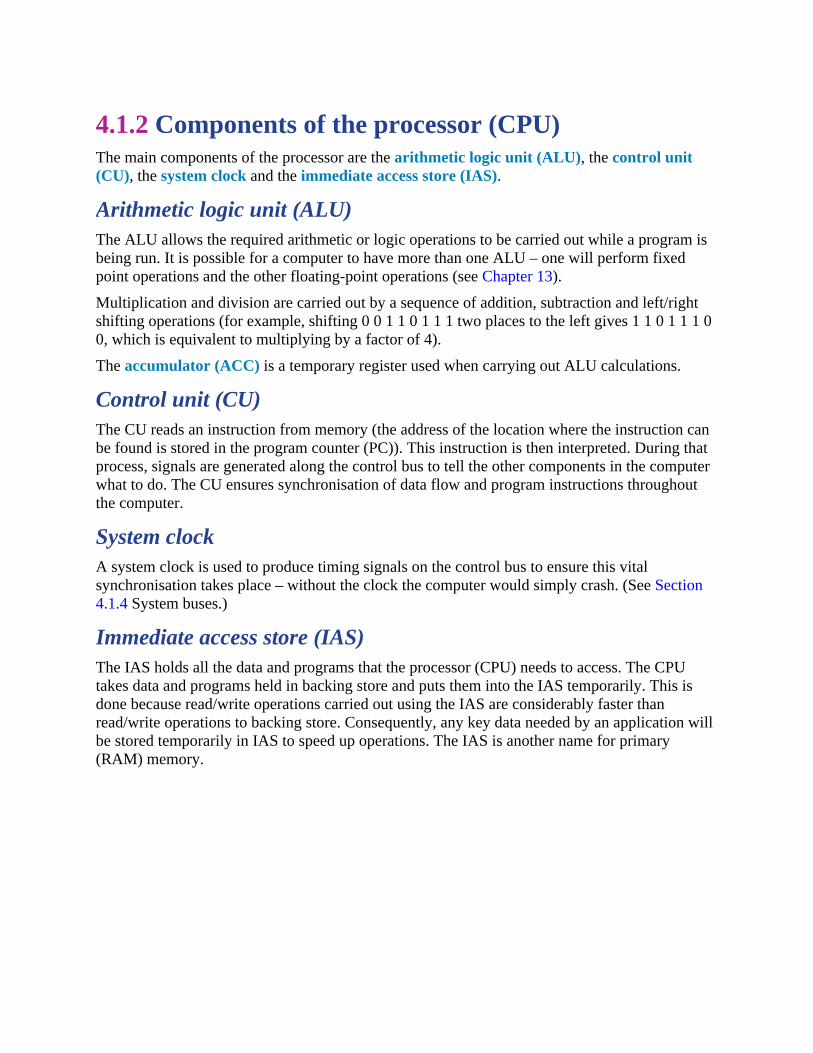
4.1.2 Components of the processor (CPU)The main components of the processor are the arithmetic logic unit (ALU), the control unit(CU), the system clock and the immediate access store (IAS).
Arithmetic logic unit (ALU)The ALU allows the required arithmetic or logic operations to be carried out while a program isbeing run. It is possible for a computer to have more than one ALU – one will perform fixedpoint operations and the other floating-point operations (see Chapter 13).
Multiplication and division are carried out by a sequence of addition, subtraction and left/rightshifting operations (for example, shifting 0 0 1 1 0 1 1 1 two places to the left gives 1 1 0 1 1 1 00, which is equivalent to multiplying by a factor of 4).
The accumulator (ACC) is a temporary register used when carrying out ALU calculations.
Control unit (CU)The CU reads an instruction from memory (the address of the location where the instruction canbe found is stored in the program counter (PC)). This instruction is then interpreted. During thatprocess, signals are generated along the control bus to tell the other components in the computerwhat to do. The CU ensures synchronisation of data flow and program instructions throughoutthe computer.
System clockA system clock is used to produce timing signals on the control bus to ensure this vitalsynchronisation takes place – without the clock the computer would simply crash. (See Section4.1.4 System buses.)
Immediate access store (IAS)The IAS holds all the data and programs that the processor (CPU) needs to access. The CPUtakes data and programs held in backing store and puts them into the IAS temporarily. This isdone because read/write operations carried out using the IAS are considerably faster thanread/write operations to backing store. Consequently, any key data needed by an application willbe stored temporarily in IAS to speed up operations. The IAS is another name for primary(RAM) memory.

4.1.3 RegistersOne of the most fundamental components of the Von Neumann system is the register. Registerscan be general purpose or special purpose. General purpose registers hold data that is frequentlyused by the CPU or can be used by the programmer when addressing the CPU directly. Theaccumulator is a good example of a general purpose register and will be used as such throughoutthis book. Special purpose registers have a specific function within the CPU and hold theprogram state.
The most common special registers referred to in this book are shown in Table 4.1. The use ofmany of these registers is explained more fully in Section 4.1.6 (fetch-execute cycle) and inSection 4.2 (tracing of assembly code programs).
Register Abbreviation Function/purpose of register
currentinstructionregister
CIR stores the current instruction being decoded and executed
index register IX used when carrying out index addressing operations(assembly code)
memoryaddressregister
MAR stores the address of the memory location currently being readfrom or written to
memorydata/bufferregister
MDR/MBR stores data which has just been read from memory or datawhich is about to be written to memory (sometimes referredto as MBR)
programcounter
PC stores the address where the next instruction to be read can befound
status register SR contain bits which can be set or cleared depending on theoperation (for example, to indicate overflow in a calculation)
Table 4.1 Common registers
All of the registers listed in Table 4.1 (apart from status and index registers) are used in the fetch-execute cycle, which is covered later in this chapter.
Index registers are best explained when looking at addressing techniques in assembly code(again, this is covered later in the chapter).
A status register is used when an instruction requires some form of arithmetic or logicprocessing. Each bit is known as a flag. Most systems have the following four flags.• Carry flag (C) is set to 1 if there is a CARRY following an addition operation (refer to Chapter
1).• Negative flag (N) is set to 1 if the result of a calculation yields a NEGATIVE value.• Overflow flag (V) is set to 1 if an arithmetic operation results in an OVERFLOW being

produced.• Zero flag (Z) is set to 1 if the result of an arithmetic or logic operation is ZERO.
Consider this arithmetic operation:
Since we have two positive numbers being added, the answer should not be negative. The flagsindicate two errors: a negative result, and an overflow occurred.
Now consider this operation:
Since we have two negative numbers being added, the answer should be negative. The flagsindicate that two errors have occurred: a carry has been generated, and a ninth bit overflow hasoccurred.
Other flags can be generated, such as a parity flag, an interrupt flag or a half-carry flag.
EXTENSION ACTIVITY 4AFind out what conditions could cause:a) a parity flag (P) being set to 1b) an interrupt flag (I) being set to 1c) a zero flag (Z) being set to 1d) a half-carry flag (H) being set to 1.

4.1.4 System buses
Figure 4.2 System buses
(System) buses are used in computers as a parallel transmission component; each wire in the bustransmits one bit of data. There are three common buses used in the Von Neumann architectureknown as address bus, data bus and control bus.
Address busAs the name suggests, the address bus carries addresses throughout the computer system.Between the CPU and memory the address bus is unidirectional (in other words, bits can travelin one direction only). This prevents addresses being carried back to the CPU, which would beundesirable.
The width of a bus is important. The wider the bus, the more memory locations which can bedirectly addressed at any given time; for example, a bus of width 16 bits can address 216 (65 536)memory locations, whereas a bus width of 32 bits allows 4 294 967 296 memory locations to besimultaneously addressed. Even this is not large enough for modern computers, but thetechnology behind even wider buses is outside the scope of this book.
Data busThe data bus is bidirectional (in other words, it allows data to be sent in both directions alongthe bus). This means data can be carried from CPU to memory (and vice versa) as well as to andfrom input/output devices. It is important to point out that data can be an address, an instructionor a numerical value. As with the address bus, the width of the data bus is important: the widerthe bus, the larger the word length that can be transported. (A word is a group of bits which canbe regarded as a single unit, for example, 16-bit, 32-bit or 64-bit word lengths are the mostcommon). Larger word lengths can improve the computer’s overall performance.
Control bus

The control bus is also bidirectional. It carries signals from the CU to all the other computercomponents. It is usually 8-bits wide since it only carries control signals.
It is worth mentioning here the role of the system clock. The clock defines the clock cycle whichsynchronises all computer operations. As mentioned earlier, the control bus transmits timingsignals, ensuring everything is fully synchronised. By increasing clock speed, the processingspeed of the computer is also increased (a typical current value is 3.5 GHz – which means 3.5billion clock cycles a second). Although the speed of the computer may have been increased, it isnot possible to say that a computer’s overall performance is necessarily increased by using ahigher clock speed. Four other factors need to be considered.
1 Width of the address bus and data bus can affect computer performance.2 Overclocking: the clock speed can be changed by accessing the BIOS basic input/output
system (BIOS) and altering the settings. However, using a clock speed higher than thecomputer was designed for can lead to problems, such as– execution of instructions outside design limits, which can lead to seriously unsynchronised
operations (in other words, an instruction is unable to complete in time before the next oneis due to be executed) and the computer would frequently crash and become unstable
– serious overheating of the CPU leading to unreliable performance.
3 The use of cache memory can also improve processor performance. It is similar to RAM inthat its contents are lost when the power is turned off. Cache uses SRAM (see Chapter 3)whereas most computers use DRAM for main memory. Therefore, cache memories will havefaster access times, since there is no need to keep refreshing, which slows down access time.When a processor reads memory, it first checks out cache and then moves on to main memoryif the required data is not there. Cache memory stores frequently used instructions and datathat need to be accessed faster. This improves processor performance.
4 The use of a different number of cores (one core is made up of an ALU, a CU and theregisters) can improve computer performance. Many computers are dual core (the CPU ismade up of two cores) or quad core (the CPU is made up of four cores). The idea of usingmore cores alleviates the need to continually increase clock speeds. However, doubling thenumber of cores does not necessarily double the computer’s performance since we have totake into account the need for the CPU to communicate with each core; this will reduce overallperformance. For example– dual core has one channel and needs the CPU to communicate with both cores, reducing
some of the potential increase in its performance– quad core has six channels and needs the CPU to communicate with all four cores,
considerably reducing potential performance.
Figure 4.3 Two cores, one channel (left) and four cores, six channels (right)
All of these factors need to be taken into account when considering computer performance.

In summary• increasing bus width (data and address buses) increases the performance and speed of a
computer system• increasing clock speed usually increases the speed of a computer• a computer’s performance can be changed by altering bus width, clock speed and use of multi-
core CPUs• use of cache memories can also speed up a processor’s performance.

4.1.5 Computer portsInput and output devices are connected to a computer via ports. The interaction of the ports withconnected input and output is controlled by the control unit. Here we will summarise some of themore common types of ports found on modern computers.
Figure 4.4 (from left to right) USB cable, HDMI cable, VGA cable
USB portsThe Universal Serial Bus (USB) is an asynchronous serial data transmission method. It hasquickly become the standard method for transferring data between a computer and a number ofdevices.
The USB cable consists of a four-wired shielded cable, with two wires for power and the earth,and two wires used for data transmission. When a device is plugged into a computer using one ofthe USB ports• the computer automatically detects that a device is present (this is due to a small change in the
voltage level on the data signal wires in the cable)• the device is automatically recognised, and the appropriate device driver is loaded up so that
computer and device can communicate effectively• if a new device is detected, the computer will look for the device driver which matches the
device. If this is not available, the user is prompted to download the appropriate software.
The USB system has become the industry standard, but there are still pros and cons to using thissystem, as summarised in Table 4.2.
Pros of USB system Cons of USB system
• devices plugged into the computer areautomatically detected and device drivers areautomatically loaded up
• the connectors can only fit one way, which preventsincorrect connections being made
• this has become the industry standard, which meansthat considerable support is available to users
• several different data transmission rates aresupported
• newer USB standards are backward compatible
• the present transmission rate islimited to less than 500 megabitsper second
• the maximum cable length ispresently about five metres
• the older USB standard (such as1.1) may not be supported in thenear future

with older USB standards
Table 4.2 Pros and cons of the USB system
High-definition multimedia interface (HDMI)High-definition multimedia interface (HDMI) ports allow output (both audio and visual) froma computer to an HDMI-enabled device. They support high-definition signals (enhanced orstandard). HDMI was introduced as a digital replacement for the older Video Graphics Array(VGA) analogue system. Modern HD (high definition) televisions have the following features,which are making VGA a redundant technology:• They use a widescreen format (16:9 aspect ratio).• The screens use a greater number of pixels (typically 1920 × 1080).• The screens have a faster refresh rate (such as 120 Hz or 120 frames a second).• The range of colours is extremely large (some companies claim up to four million different
colour variations).
This means that modern HD televisions require more data, which has to be received at a muchfaster rate than with older televisions (around 10 gigabits per second). HDMI increases thebandwidth, making it possible to supply the necessary data for high quality sound and visualeffects.
HDMI can also afford some protection against piracy since it uses high-bandwidth digital copyprotection (HDCP). HDCP uses a type of authentication protocol (see Chapters 6 and 17). Forexample, a Blu-ray player will check the authentication key of the device it is sending data to(such as an HD television). If the key can be authenticated, then handshaking takes place and theBlu-ray can start to transmit data to the connected device.
Video Graphics Array (VGA)VGA was introduced at the end of the 1980s. VGA supports 640 × 480 pixel resolution on atelevision or monitor screen. It can also handle a refresh rate of up to 60 Hz (60 frames a second)provided there are only 16 different colours being used. If the pixel density is reduced to 200 ×320, then it can support up to 256 colours.
The technology is analogue and, as mentioned in the previous section, is being phased out.
Table 4.3 summarises the pros and cons of HDMI and VGA.
Pros of HDMI Cons of HDMI
• the current standard for moderntelevisions and monitors
• allows for a very fast data transfer rate• improved security (helps prevent piracy)• supports modern digital systems
• not a very robust connection (easy to breakconnection when simply moving device)
• limited cable length to retain good signal• there are currently five cable/connection
standards
Pros of VGA Cons of VGA

• simpler technology• only one standard available• it is easy to split the signal and connect a
number of devices from one source• the connection is very secure
• old out-dated analogue technology• it is easy to bend the pins when making
connections• the cables must be of a very high grade to
ensure good undistorted signal
Table 4.3 Pros and cons of HDMI and VGA

4.1.6 Fetch-execute cycleWe have already considered the role of buses and registers in the processor. This next sectionshows how an instruction is decoded and executed in the fetch-execute cycle using variouscomponents in the processor.
To execute a set of instructions, the processor first fetches data and instructions from memoryand stores them in suitable registers. Both the address bus and data bus are used in this process.Once this is done, each instruction needs to be decoded before being executed.
FetchThe next instruction is fetched from the memory address currently stored in the programcounter (PC) and is then stored in the current instruction register (CIR). The PC is thenincremented (increased by 1) so that the next instruction can be processed. This is decoded sothat each instruction can be interpreted in the next part of the cycle.
ExecuteThe processor passes the decoded instruction as a set of control signals to the appropriatecomponents within the computer system. This allows each instruction to be carried out in itslogical sequence.
Figure 4.5 shows how the fetch-execute cycle is carried out in the Von Neumann computermodel.

Figure 4.5 How the fetch-execute cycle is carried out in the Von Neumann computer model
When registers are involved, it is possible to describe what is happening by using RegisterTransfer Notation (RTN). In its simplest form:
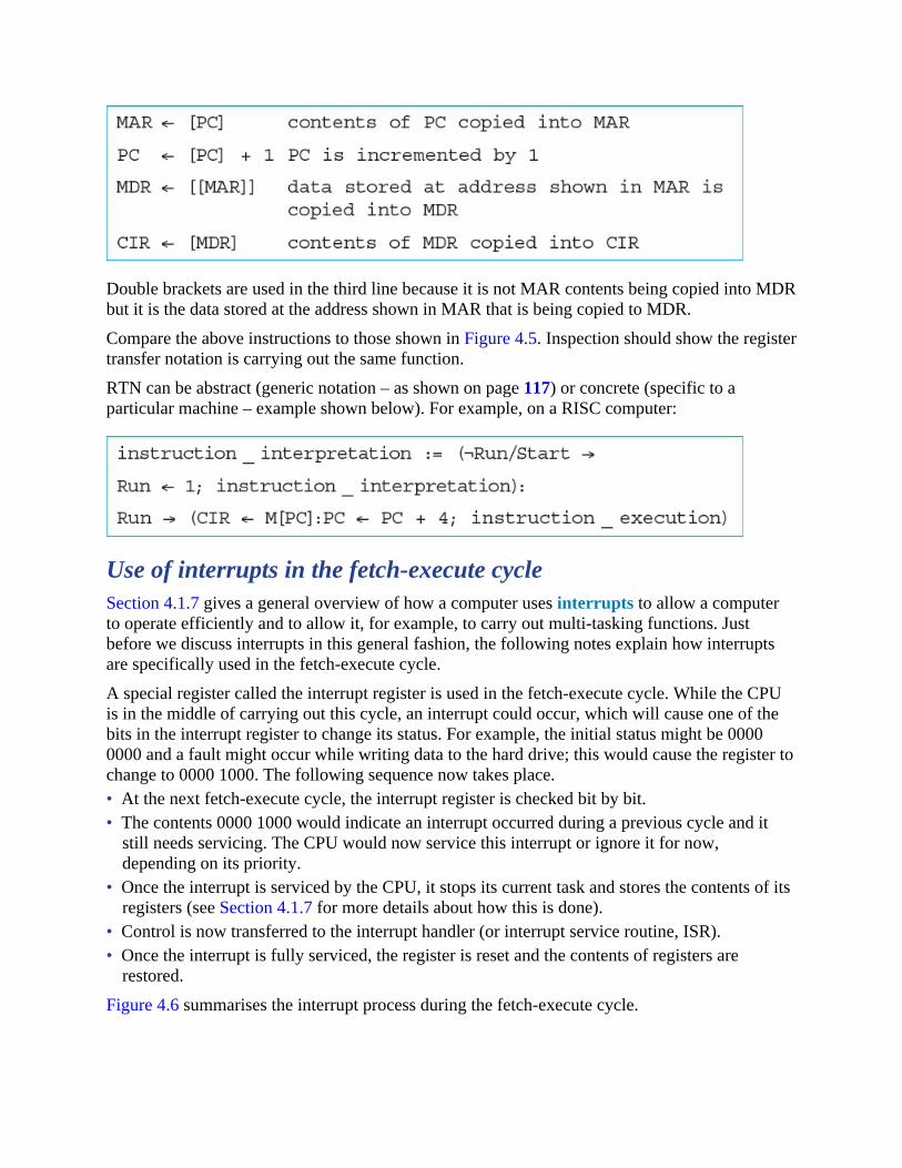
Double brackets are used in the third line because it is not MAR contents being copied into MDRbut it is the data stored at the address shown in MAR that is being copied to MDR.
Compare the above instructions to those shown in Figure 4.5. Inspection should show the registertransfer notation is carrying out the same function.
RTN can be abstract (generic notation – as shown on page 117) or concrete (specific to aparticular machine – example shown below). For example, on a RISC computer:
Use of interrupts in the fetch-execute cycleSection 4.1.7 gives a general overview of how a computer uses interrupts to allow a computerto operate efficiently and to allow it, for example, to carry out multi-tasking functions. Justbefore we discuss interrupts in this general fashion, the following notes explain how interruptsare specifically used in the fetch-execute cycle.
A special register called the interrupt register is used in the fetch-execute cycle. While the CPUis in the middle of carrying out this cycle, an interrupt could occur, which will cause one of thebits in the interrupt register to change its status. For example, the initial status might be 00000000 and a fault might occur while writing data to the hard drive; this would cause the register tochange to 0000 1000. The following sequence now takes place.• At the next fetch-execute cycle, the interrupt register is checked bit by bit.• The contents 0000 1000 would indicate an interrupt occurred during a previous cycle and it
still needs servicing. The CPU would now service this interrupt or ignore it for now,depending on its priority.
• Once the interrupt is serviced by the CPU, it stops its current task and stores the contents of itsregisters (see Section 4.1.7 for more details about how this is done).
• Control is now transferred to the interrupt handler (or interrupt service routine, ISR).• Once the interrupt is fully serviced, the register is reset and the contents of registers are
restored.
Figure 4.6 summarises the interrupt process during the fetch-execute cycle.

Figure 4.6 The interrupt process during the fetch-execute cycle
4.1.7 InterruptsAn interrupt is a signal sent from a device or from software to the processor. This will cause theprocessor to temporarily stop what it is doing and service the interrupt. Interrupts can be causedby, for example• a timing signal• input/output processes (a disk drive is ready to receive more data, for example)• a hardware fault (an error has occurred such as a paper jam in a printer, for example)• user interaction (the user pressed a key to interrupt the current process, such as <CTRL>
<ALT><BREAK>, for example)• a software error that cannot be ignored (if an .exe file could not be found to initiate the
execution of a program OR an attempt to divide by zero, for example).
Once the interrupt signal is received, the processor either carries on with what it was doing orstops to service the device/program that generated the interrupt. The computer needs to identifythe interrupt type and also establish the level of interrupt priority.
Interrupts allow computers to carry out many tasks or to have several windows open at the sametime. An example would be downloading a file from the internet at the same time as listening tosome music from the computer library. Whenever an interrupt is serviced, the status of thecurrent task being run is saved. The contents of the program counter and other registers aresaved. Then, the interrupt service routine (ISR) is executed by loading the start address intothe program counter. Once the interrupt has been fully serviced, the status of the interrupted taskis reinstated (contents of saved registers retrieved) and it continues from the point prior to theinterrupt being sent.
ACTIVITY 4a1 a) Describe the functions of the following registers.
i) Current instruction registerii) Memory address registeriii) Program counter
b) Status registers contain flags. Three such flags are named N, C and V.i) What does each of the three flags represent?ii) Give an example of the use of each of the three flags.
2 a) Name three buses used in the Von Neumann architecture.b) Describe the function of each named bus.c) Describe how bus width and clock speed can affect computer performance.
3 Copy the diagram below and connect each feature to the correct port, HDMI or VGA.

4 a) What is meant by the fetch-execute cycle?b) Using register transfer notation, show the main stages in a typical fetch-execute cycle.
5 Copy and complete this paragraph by using terms from this chapter.
The processor_______________data and instructions required for an application andtemporarily stores them in the_______________until they can be processed.
The_______________is used to hold the address of the next instruction to be executed. Thisaddress is copied to the_______________using the_______________.
The contents at this address are stored in the_______________.
Each instruction is then_______________and finally_______________sendingout_______________using the_______________. Any calculations carried out are doneusing the_______________. During any calculations, data is temporarily held in a specialregister known as the_______________.

4.2 Assembly languageWHAT YOU SHOULD ALREADY KNOWTry these three questions before you start the second part of this chapter.1 a) Name two types of low-level programming language.
b) Name the only type of programming language that a CPU recognises.c) Why do programmers find writing in this type of programming language difficult?
2 Find at least two different types of CPU and the language they use.3 Look at your computer and/or laptop and/or phone and list the programming language(s)
they use.
Key termsMachine code – the programming language that the CPU uses.
Instruction – a single operation performed by a CPU.
Assembly language – a low-level chip/machine specific programming language that usesmnemonics.
Opcode – short for operation code, the part of a machine code instruction that identifies theaction the CPU will perform.
Operand – the part of a machine code instruction that identifies the data to be used by theCPU.
Source code – a computer program before translation into machine code.
Assembler – a computer program that translates programming code written in assemblylanguage into machine code. Assemblers can be one pass or two pass.
Instruction set – the complete set of machine code instructions used by a CPU.
Object code – a computer program after translation into machine code.
Addressing modes – different methods of using the operand part of a machine code instructionas a memory address.
Absolute addressing – mode of addressing in which the contents of the memory location inthe operand are used.
Direct addressing – mode of addressing in which the contents of the memory location in theoperand are used, which is the same as absolute addressing.
Indirect addressing – mode of addressing in which the contents of the contents of the memorylocation in the operand are used.
Indexed addressing – mode of addressing in which the contents of the memory location foundby adding the contents of the index register (IR) to the address of the memory location in the

operand are used.
Immediate addressing – mode of addressing in which the value of the operand only is used.
Relative addressing – mode of addressing in which the memory address used is the currentmemory address added to the operand.
Symbolic addressing – mode of addressing used in assembly language programming, where alabel is used instead of a value.
4.2.1 Assembly language and machine codeThe only programming language that a CPU can use is machine code. Every different type ofcomputer/chip has its own set of machine code instructions. A computer program stored in mainmemory is a series of machine code instructions that the CPU can automatically carry out duringthe fetch-execute cycle. Each machine code instruction performs one simple task, for example,storing a value in a memory location at a specified address. Machine code is binary, it issometimes displayed on a screen as hexadecimal so that human programmers can understandmachine code instructions more easily.
Writing programs in machine code is a specialised task that is very time consuming and oftenerror prone, as the only way to test a program written in machine code is to run it and see whathappens. In order to shorten the development time for writing computer programs, otherprogramming languages were developed, where the instructions were easier to learn andunderstand. Any program not written in machine code needs to be translated before the CPU cancarry out the instructions, so language translators were developed.
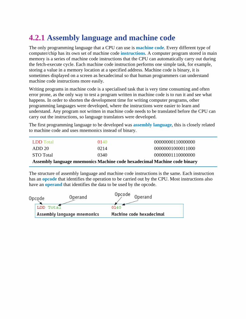
The first programming language to be developed was assembly language, this is closely relatedto machine code and uses mnemonics instead of binary.
LDD Total 0140 00000000110000000ADD 20 0214 00000001000011000STO Total 0340 00000001110000000Assembly language mnemonics Machine code hexadecimal Machine code binary
The structure of assembly language and machine code instructions is the same. Each instructionhas an opcode that identifies the operation to be carried out by the CPU. Most instructions alsohave an operand that identifies the data to be used by the opcode.

4.2.2 Stages of assemblyBefore a program written in assembly language (source code) can be executed, it needs to betranslated into machine code. The translation is performed by a program called an assembler. Anassembler translates each assembly language instruction into a machine code instruction. Anassembler also checks the syntax of the assembly language program to ensure that only opcodesfrom the appropriate machine code instruction set are used. This speeds up the developmenttime, as some errors are identified during translation before the program is executed.
There are two types of assembler: single pass assemblers and two pass assemblers. A single passassembler puts the machine code instructions straight into the computer memory to be executed.A two pass assembler produces an object program in machine code that can be stored, loadedthen executed at a later stage. This requires the use of another program called a loader. Two passassemblers need to scan the source program twice, so they can replace labels in the assemblyprogram with memory addresses in the machine code program.
Pass 1• Read the assembly language program one line at a time.• Ignore anything not required, such as comments.• Allocate a memory address for the line of code.• Check the opcode is in the instruction set.• Add any new labels to the symbol table with the address, if known.• Place address of labelled instruction in the symbol table.
Pass 2• Read the assembly language program one line at a time.• Generate object code, including opcode and operand, from the symbol table generated in Pass
1.• Save or execute the program.
The second pass is required as some labels may be referred to before their address is known. Forexample, Found is a forward reference for the JPN instruction.
Label Opcode OperandNotfound: LDD 200 CMP #0 JPN Found JPE NotfoundFound: OUT

If the program is to be loaded at memory address 100, and each memory location contains 16bits, the symbol table for this small section of program would look like this:
Label AddressNotfound 100Found 104

4.2.3 Assembly language instructionsThere are different types of assembly language instructions. Examples of each type are givenbelow.
Data movement instructionsThese instructions allow data stored at one location to be copied into the accumulator. This datacan then be stored at another location, used in a calculation, used for a comparison or output.
Instruction Explanation
Opcode Operand
LDM #n Load the number into ACC (immediate addressing is used)
LDD <address> Load the contents of the specified address into ACC (direct or absoluteaddressing is used)
LDI <address> The address to be used is the contents of the specified address. Load thecontents of the contents of the given address into ACC (indirectaddressing is used)
LDX <address> The address to be used is the specified address plus the contents of theindex register. Load the contents of this calculated address into ACC(indexed addressing is used)
LDR #n Load the number n into IX (immediate addressing is used)
LDR ACC Load the number in the accumulator into IX
MOV <register> Move the contents of the accumulator to the register (IX)
STO <address> Store the contents of ACC into the specified address (direct or absoluteaddressing is used)
END Return control to the operating system
ACC is the single accumulatorIX is the Index RegisterAll numbers are denary unless identified as binary or hexadecimalB is a binary number, for example B01000011& is a hexadecimal number, for example &7B# is a denary number
Table 4.4 Data movement instructions
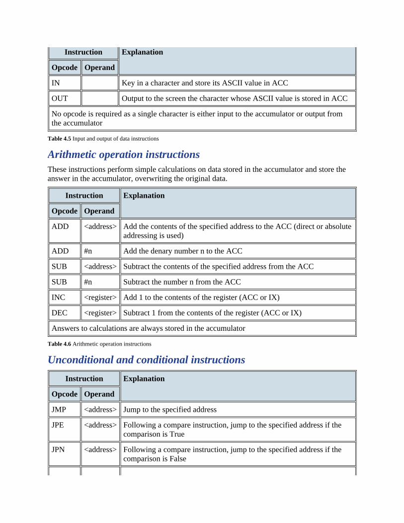
Input and output of data instructionsThese instructions allow data to be read from the keyboard or output to the screen.
Instruction Explanation
Opcode Operand
IN Key in a character and store its ASCII value in ACC
OUT Output to the screen the character whose ASCII value is stored in ACC
No opcode is required as a single character is either input to the accumulator or output fromthe accumulator
Table 4.5 Input and output of data instructions
Arithmetic operation instructionsThese instructions perform simple calculations on data stored in the accumulator and store theanswer in the accumulator, overwriting the original data.
Instruction Explanation
Opcode Operand
ADD <address> Add the contents of the specified address to the ACC (direct or absoluteaddressing is used)
ADD #n Add the denary number n to the ACC
SUB <address> Subtract the contents of the specified address from the ACC
SUB #n Subtract the number n from the ACC
INC <register> Add 1 to the contents of the register (ACC or IX)
DEC <register> Subtract 1 from the contents of the register (ACC or IX)
Answers to calculations are always stored in the accumulator
Table 4.6 Arithmetic operation instructions
Unconditional and conditional instructions
Instruction Explanation
Opcode Operand
JMP <address> Jump to the specified address
JPE <address> Following a compare instruction, jump to the specified address if thecomparison is True
JPN <address> Following a compare instruction, jump to the specified address if thecomparison is False

END Returns control to the operating system
Jump means change the PC to the address specified, so the next instruction to be executed isthe one stored at the specified address, not the one stored at the next location in memory
Table 4.7 Unconditional and conditional instructions
Compare instructions
Instruction Explanation
Opcode Operand
CMP <address> Compare the contents of ACC with the contents of the specified address(direct or absolute addressing is used)
CMP #n Compare the contents of ACC with the number n
CMI <address> The address to be used is the contents of the specified address; comparethe contents of the contents of the given address with ACC (indirectaddressing is used)
The contents of the accumulator are always compared
Table 4.8 Compare instructions

4.2.4 Addressing modesAssembly language and machine code programs use different addressing modes depending onthe requirements of the program.
Absolute addressing – the contents of the memory location in the operand are used. Forexample, if the memory location with address 200 contained the value 20, the assembly languageinstruction LDD 200 would store 20 in the accumulator.
Direct addressing – the contents of the memory location in the operand are used. For example,if the memory location with address 200 contained the value 20, the assembly languageinstruction LDD 200 would store 20 in the accumulator. Absolute and direct addressing are thesame.
Indirect addressing – the contents of the contents of the memory location in the operand areused. For example, if the memory location with address 200 contained the value 20 and thememory location with address 20 contained the value 5, the assembly language instruction LDI200 would store 5 in the accumulator.
Indexed addressing – the contents of the memory location found by adding the contents of theindex register (IR) to the address of the memory location in the operand are used. For example, ifIR contained the value 4 and memory location with address 204 contained the value 17, theassembly language instruction LDX 200 would store 17 in the accumulator.
Immediate addressing – the value of the operand only is used. For example, the assemblylanguage instruction LDM #200 would store 200 in the accumulator.
Relative addressing – the memory address used is the current memory address added to theoperand. For example, JMR #5 would transfer control to the instruction 5 locations after thecurrent instruction.
Symbolic addressing – only used in assembly language programming. A label is used instead ofa value. For example, if the memory location with address labelled MyStore contained the value20, the assembly language instruction LDD MyStore would store 20 in the accumulator.
Labels make it easier to alter assembly language programs because when absolute addresses areused every reference to that address needs to be edited if an extra instruction is added, forexample.
Label Instruction Explanation
Opcode Operand
<label>: <opcode> <operand> Labels an instruction
<label>: n Gives a symbolic address <label> to the memory locationwith the contents n
Table 4.9 Labels

4.2.5 Simple assembly language programsA program written in assembly language will need many more instructions than a programwritten in a high-level language to perform the same task.
In a high-level language, adding three numbers together and storing the answer would typicallybe written as a single instruction:
total = first + second + third
The same task written in assembly language could look like this:
Label Opcode Operandstart: LDD first ADD second ADD third STO total END first: #20 second: #30 third: #40 total: #0
If the program is to be loaded at memory address 100 after translation and each memory locationcontains 16 bits, the symbol table for this small section of program would look like this:
Label Address
start 100
first 106
second 107
third 108
total 109
When this section of code is executed, the contents of ACC, CIR and the variables used can betraced using a trace table.

In a high-level language, adding a list of numbers together and storing the answer wouldtypically be written using a loop.
The same task written in assembly language would require the use of the index register (IX). Theassembly language program could look like this:

If the program is to be loaded at memory address 100 after translation and each memory locationcontains 16 bits, the symbol table for this small section of program would look like this:
Label Address
loop 104
number 115
counter 118
total 119
When this section of code is executed the contents of ACC, CIR, IX and the variables used canbe traced using a trace table:

ACTIVITY 4B1 a) State the contents of the accumulator after the following instructions have been executed.
The memory location with address 200 contains 300, the memory location with address300 contains 50.

i) LDM #200ii) LDD 200iii) LDI 200
b) Write an assembly language instruction to:i) compare the accumulator with 5ii) jump to address 100 if the comparison is true.
2 a) Copy and complete the symbol table for this assembly language program. Assume thatthe translated program will start at memory address 100.
b) Complete a trace table to show the execution of this assembly language program.c) State the task that this assembly language program performs.
Label Opcode Operand LDD number1 SUB number2 ADD number3 CMP #10 JPE nomore ADD number4
nomore: STO total END number1: #30 number2: #40 number3: #20 number4: #50
total: #0
3 a) Using the assembly language instructions given in this section, write an assemblylanguage program to output the ASCII value of each element of an array of fourelements.
b) Complete the symbol table for your assembly language program. Assume that thetranslated program will start at memory address 100.
c) Complete a trace table to show the execution of your assembly language program.
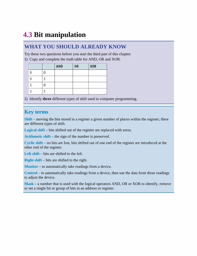
4.3 Bit manipulationWHAT YOU SHOULD ALREADY KNOWTry these two questions before you start the third part of this chapter.1) Copy and complete the truth table for AND, OR and XOR.
2) Identify three different types of shift used in computer programming.
Key termsShift – moving the bits stored in a register a given number of places within the register; thereare different types of shift.
Logical shift – bits shifted out of the register are replaced with zeros.
Arithmetic shift – the sign of the number is preserved.
Cyclic shift – no bits are lost, bits shifted out of one end of the register are introduced at theother end of the register.
Left shift – bits are shifted to the left.
Right shift – bits are shifted to the right.
Monitor – to automatically take readings from a device.
Control – to automatically take readings from a device, then use the data from those readingsto adjust the device.
Mask – a number that is used with the logical operators AND, OR or XOR to identify, removeor set a single bit or group of bits in an address or register.

4.3.1 Binary shiftsA shift involves moving the bits stored in a register a given number of places within the register.Each bit within the register may be used for a different purpose. For example, in the IR each bitidentifies a different interrupt.
There are several different types of shift.
Logical shift – bits shifted out of the register are replaced with zeros. For example, an 8-bitregister containing the binary value 10101111 shifted left logically three places would become01111000.
Arithmetic shift – the sign of the number is preserved. For example, an 8-bit register containingthe binary value 10101111 shifted right arithmetically three places would become 11110101.Arithmetic shifts can be used for multiplication or division by powers of two.
Cyclic shift – no bits are lost during a shift. Bits shifted out of one end of the register areintroduced at the other end of the register. For example, an 8-bit register containing the binaryvalue 10101111 shifted left cyclically three places would become 01111101.
Left shift – bits are shifted to the left; gives the direction of shift for logical, arithmetic andcyclic shifts.
Right shift – bits are shifted to the right; gives the direction of shift for logical, arithmetic andcyclic shifts.
Table 4.10 shows the logical shifts that you are expected to use in assembly languageprogramming.
Instruction Explanation
Opcode Operand
LSL n Bits in ACC are shifted logically n places to the left. Zeros areintroduced on the right-hand end
LSR n Bits in ACC are shifted logically n places to the right. Zeros areintroduced on the left-hand end
Shifts are always performed on the ACC
Table 4.10 Logical shifts in assembly language programming
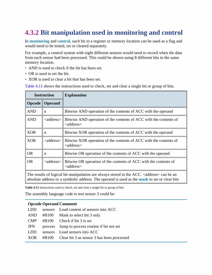
4.3.2 Bit manipulation used in monitoring and controlIn monitoring and control, each bit in a register or memory location can be used as a flag andwould need to be tested, set or cleared separately.
For example, a control system with eight different sensors would need to record when the datafrom each sensor had been processed. This could be shown using 8 different bits in the samememory location.• AND is used to check if the bit has been set.• OR is used to set the bit.• XOR is used to clear a bit that has been set.
Table 4.11 shows the instructions used to check, set and clear a single bit or group of bits.
Instruction Explanation
Opcode Operand
AND n Bitwise AND operation of the contents of ACC with the operand
AND <address> Bitwise AND operation of the contents of ACC with the contents of<address>
XOR n Bitwise XOR operation of the contents of ACC with the operand
XOR <address> Bitwise XOR operation of the contents of ACC with the contents of<address>
OR n Bitwise OR operation of the contents of ACC with the operand
OR <address> Bitwise OR operation of the contents of ACC with the contents of<address>
The results of logical bit manipulation are always stored in the ACC. <address> can be anabsolute address or a symbolic address. The operand is used as the mask to set or clear bits
Table 4.11 Instructions used to check, set and clear a single bit or group of bits
The assembly language code to test sensor 3 could be:
Opcode Operand CommentLDD sensors Load content of sensors into ACCAND #B100 Mask to select bit 3 onlyCMP #B100 Check if bit 3 is setJPN process Jump to process routine if bit not setLDD sensors Load sensors into ACCXOR #B100 Clear bit 3 as sensor 3 has been processed

ACTIVITY 4C1 a) State the contents of the accumulator after the following instructions have been executed.
The accumulator contains B00011001.i) LSL #4ii) LSR #5
b) Write an assembly language instruction to:i) set bit 4 in the accumulatorii) clear bit 1 in the accumulator.
2 a) Describe the difference between arithmetic shifts and logical shifts.b) Explain, with the aid of examples, how a cyclic shift works.c) This register is shown before and after it has been shifted. Identify the type of shift that
has taken place.
End of chapter questions1 a) Write these six stages of the Von Neumann fetch-execute cycle in the correct order.
[6] – instruction is copied from the MDR and is placed in the CIR – the instruction is executed – the instruction is decoded – the address contained in PC is copied to the MAR – the value in PC is incremented by 1 – instruction is copied from memory location in MAR and placed in MDR
b) Explain how the following affect the performance of a computer system.i) Width of the data bus and address bus.
[2]ii) The clock speed.
[2]iii) Use of dual core or quad core processors.
[2]c) A student accessed the BIOS on their computer. They increased the clock speed from 2.5
GHz to 3.2 GHz.Explain the potential dangers in doing this.
[2]2 a) Explain the main differences between HDMI, VGA and USB ports when sending data to
peripherals.
[5]b) Describe how interrupts can be used to service a printer printing out a large 1000 page
document.[5]
3 a) i) Name three special registers used in a typical processor.[3]
ii) Explain the purpose of the three registers named in part i).[3]
b) Explain how interrupts are used when a processor sends a document to a printer.[4]
4 A programmer is writing a program in assembly language. They need to use shiftinstructions.Describe, using examples, three types of shift instructions the programmer could use.
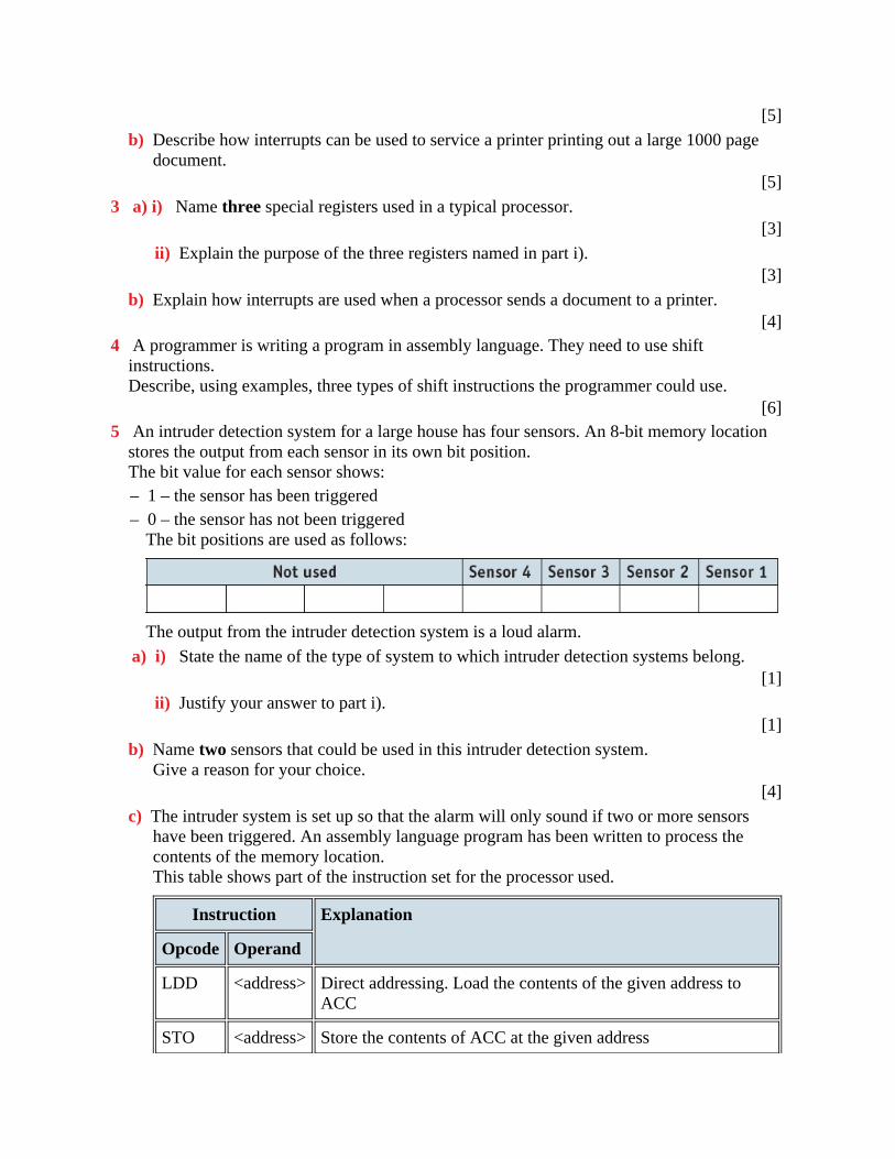
[6]5 An intruder detection system for a large house has four sensors. An 8-bit memory location
stores the output from each sensor in its own bit position.The bit value for each sensor shows:– 1 – the sensor has been triggered– 0 – the sensor has not been triggered
The bit positions are used as follows:
The output from the intruder detection system is a loud alarm.a) i) State the name of the type of system to which intruder detection systems belong.
[1]ii) Justify your answer to part i).
[1]b) Name two sensors that could be used in this intruder detection system.
Give a reason for your choice.[4]
c) The intruder system is set up so that the alarm will only sound if two or more sensorshave been triggered. An assembly language program has been written to process thecontents of the memory location.This table shows part of the instruction set for the processor used.
Instruction Explanation
Opcode Operand
LDD <address> Direct addressing. Load the contents of the given address toACC
STO <address> Store the contents of ACC at the given address

INC <register> Add 1 to the contents of the register (ACC or IX)
ADD <address> Add the contents of the given address to the contents of ACC
AND <address> Bitwise AND operation of the contents of ACC with thecontents of <address>
CMP #n Compare the contents of ACC with the number n
JMP <address> Jump to the given address
JPE <address> Following a compare instruction, jump to <address> if thecompare was True
JGT <address> Following a compare instruction, jump to <address> if thecontent of ACC is greater than the number used in the compareinstruction
END End the program and return to the operating system
Part of the assembly code is:
Opcode Operand
SENSORS: B00001010
COUNT: 0
VALUE: 1
LOOP: LDD SENSORS
AND VALUE
CMP #0
JPE ZERO
LDD COUNT
INC ACC
STO COUNT
ZERO: LDD VALUE
CMP #8
JPE EXIT
ADD VALUE
STO VALUE

JMP LOOP
EXIT: LDD COUNT
TEST: CMP …
JGT ALARM
i) Copy the table below and dry run the assembly language code.Start at LOOP and finish when EXIT is reached.
[4]
ii) The operand for the instruction labelled TEST is missing.State the missing operand.
[1]iii) The intruder detection system is improved and now has eight sensors. One
instruction in the assembly language code will need to be amended.Identify this instruction. Write the amended instruction.
[2]

Cambridge International AS & A Level Computer Science 9608 Paper 32 Q6 June2016