4-Forming Process 2
23
Pipe Extrusion
-
Upload
ahmed-awad -
Category
Documents
-
view
34 -
download
1
description
Polymer Processing
Transcript of 4-Forming Process 2
Pipe Extrusion
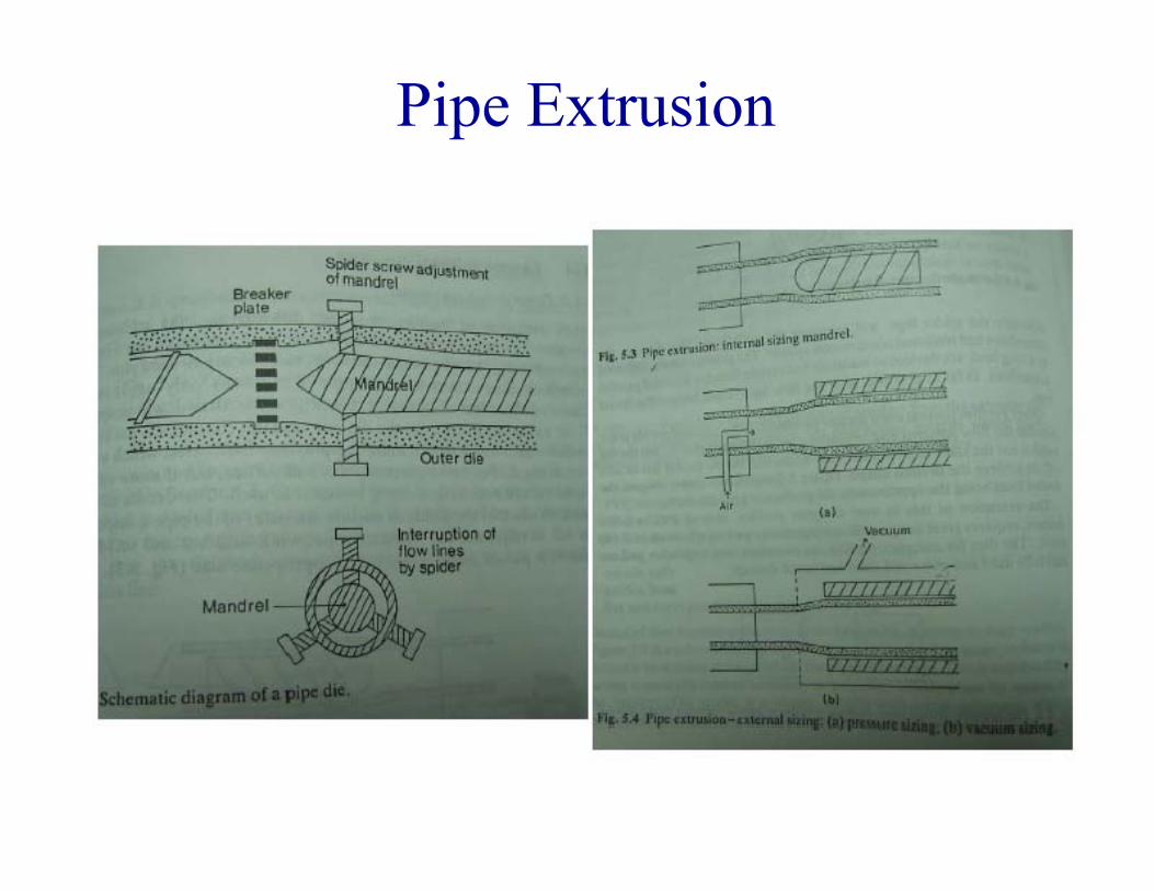
Pipe ExtrusionPIPE AND TUBING DIES:• Both pipe and tubing are made in dies with an annularp p g
die exit.• A pipe product is defined as being greater than 1 in.p p p g g
in outer diameter and a tube less than 1 in.• Dies for these products are made in two styles:
1. In-line dies (also called spider dies)2. Cross-head dies
Pipe Extrusion The in line die is the least costly for manufacture of the two The in-line die is the least costly for manufacture of the two
designs but can create defects called weld lines in the product.• Weld lines occur because the melt is split and rejoined as it passes p j p
over the spider legs. Spider-arm dies are used for poly(vinyl chloride) and other high-viscosity, heat-sensitive materials.
A cross head die can o ercome this problem b eliminating the A cross-head die can overcome this problem by eliminating thespiders. The melt enters the side of the die and turns 90o as itflows through a coat hanger-type passage that is wrapped aroundthe mandrel.
Another application for the cross-head-style tubing die is wirecoating The following adjustments are made to a cross headcoating. The following adjustments are made to a cross-headtubing die to perform wire coating:– First, instead of passing air through the core tube, a bare conductor wire is
ll d h h h b i l h di ipulled through the core tube inlet the die pin.– Second, the length of the die pin is shortened to cause the wire to contact
the melt tube before it exits the die land.
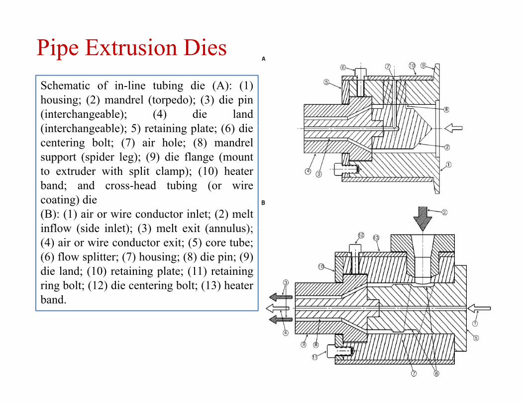
Pipe Extrusion DiesSchematic of in-line tubing die (A): (1)housing; (2) mandrel (torpedo); (3) die pin(interchangeable); (4) die land(i t h bl ) 5) t i i l t (6) di(interchangeable); 5) retaining plate; (6) diecentering bolt; (7) air hole; (8) mandrelsupport (spider leg); (9) die flange (mountto extruder with split clamp); (10) heaterp p); ( )band; and cross-head tubing (or wirecoating) die(B): (1) air or wire conductor inlet; (2) meltinflow (side inlet); (3) melt exit (annulus);inflow (side inlet); (3) melt exit (annulus);(4) air or wire conductor exit; (5) core tube;(6) flow splitter; (7) housing; (8) die pin; (9)die land; (10) retaining plate; (11) retainingring bolt; (12) die centering bolt; (13) heaterband.
Flat Film Forming Film extrusion is one of the most important processes
for plastics accounting for almost a quarter of allfor plastics accounting for almost a quarter of allthermoplastics consumed.
It has enjoyed some periods of rapid growth in recentj y p p gyears, particularly within the packaging industry
Film is defined as a sheet less than 250 μm inthickness.
There are two types of film extrusion: cast film andblown film.
Flat film and sheet extrusion In this process the extruder pumps molten resin
through a flat film or sheet die. The melt leaves the diein the form of a wide film, or sheet.
This is typically fed into a chill-roll assembly whichh d l h filstretches and cools the film
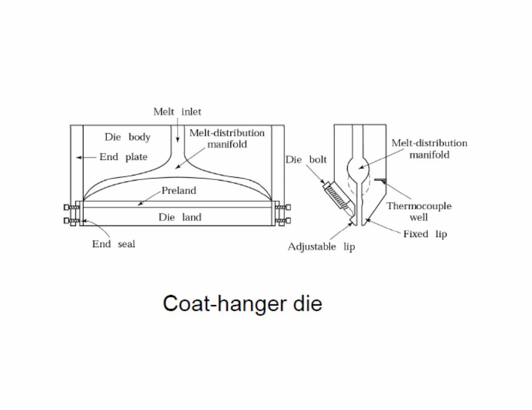
Film and sheet dies are wide, flat dies consisting oft i if ld d th di litwo pieces: a manifold and the die lip.
The manifold distributes the melt across the width ofthe die whereas the die lip controls molten filmthe die, whereas the die lip controls molten filmthickness.
Flat film and sheet extrusion
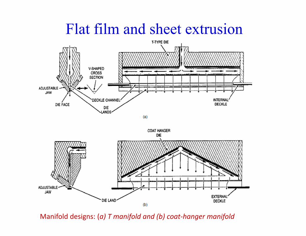
Manifold designs: (a) T manifold and (b) coat‐hanger manifold
Flat film and sheet extrusion
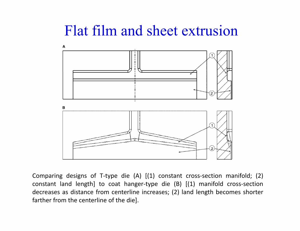
Comparing designs of T‐type die (A) [(1) constant cross‐section manifold; (2)constant land length] to coat hanger‐type die (B) [(1) manifold cross‐sectiondecreases as distance from centerline increases; (2) land length becomes shorterfarther from the centerline of the die].
Three basic manifold designs are used in flat film dies. The T design:g It is simple and easy to manufacture. Although it
produces a non-uniform pressure drop across the dieand thus causes non uniform flow through the die lipand thus causes non-uniform flow through the die lip
The distribution of the melt does not produce diedistortion.
Consequently, the use of T-dies is often limited tocoating applications with low-viscosity resins thatresist thermal degradation, as the ends of the manifoldresist thermal degradation, as the ends of the manifoldin the T-die create stagnation pockets. A commonapplication for a film die is to coat a substrate likepaperpaper
The coat-hanger manifold In the coat-hanger manifold a channel distributes theg
melt, but flow is restricted in the preland.
While the shape of the manifold channel compensates for thed h l f h di b l i dipressure drop, the placement of the die bolts permits die
distortion that varies with melt viscosity and polymer flowrate.
The fishtail design: The entire land area, rather than a flow channel, changes to
dj h d Thi i b l di ib iadjust the pressure drop. This gives better melt distribution. But, the die is massive and contains a large mass of polymer. As a result the fishtail manifold can create temperature non As a result, the fishtail manifold can create temperature non-
uniformities and degradation problems. Since they provide uniform pressure drops with less thermal
mass, coat hanger manifolds are most commonly used. Fishtail manifolds are often employed in sheet extrusion.
Chill rollers
Optimally, the molten polymer drops onto the chill roll and contacts tangentiallyroll and contacts tangentially.
The alignment or parallelism of this roll to the die is critical in relation to the falling filmcritical in relation to the falling film.
Whenever wrinkling of the film occurs on the casting roll surface it is likely that the first roll must beroll surface, it is likely that the first roll must be repositioned.
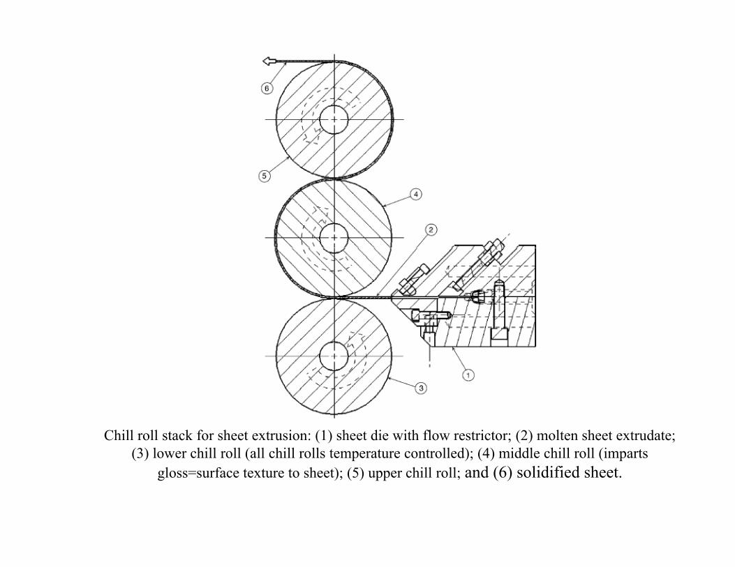
Chill roll stack for sheet extrusion: (1) sheet die with flow restrictor; (2) molten sheet extrudate; (3) lower chill roll (all chill rolls temperature controlled); (4) middle chill roll (imparts
gloss=surface texture to sheet); (5) upper chill roll; and (6) solidified sheet.
Chill rollers High gloss finish – chromium finish for highly
polished rollpolished roll Matte finish – metal rolls are sandblasted, acid
etched, or machined, Design Criteria: polymer cannot stick to rollers Thermal conductivity and conduction of heat fromThermal conductivity and conduction of heat from
molten polymer to chilled rollers At least two or more rolls
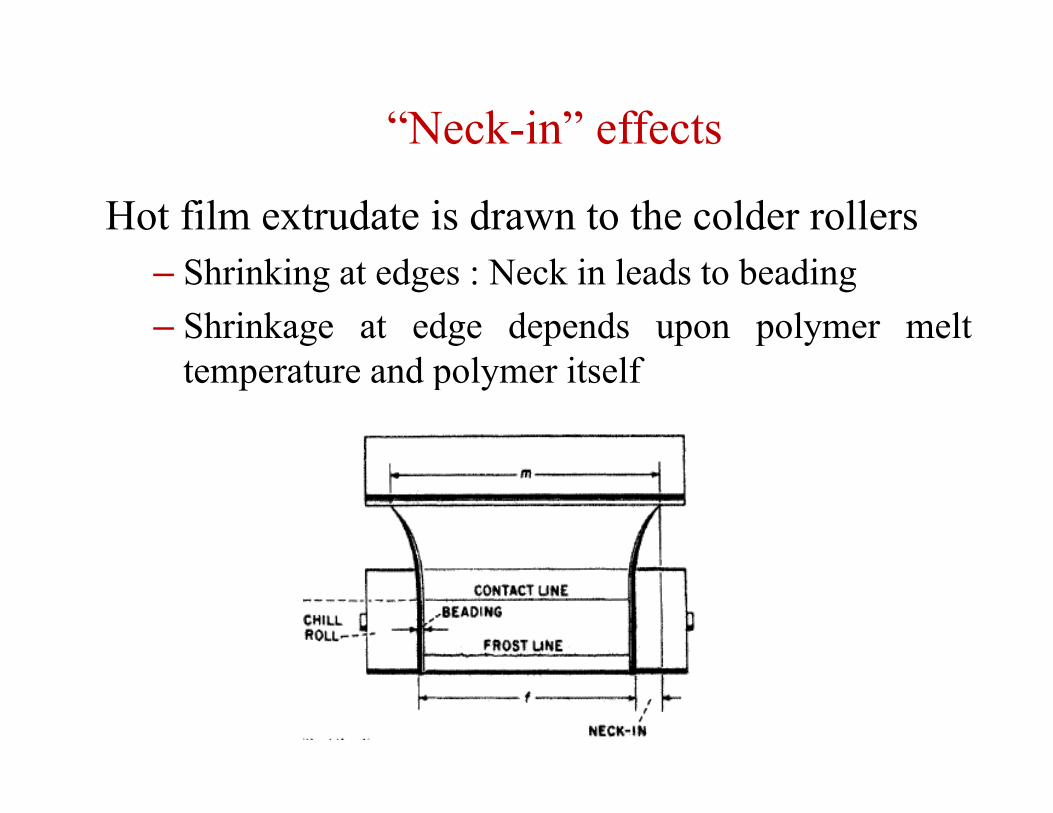
“Neck-in” effects
Hot film extrudate is drawn to the colder rollers– Shrinking at edges : Neck in leads to beading– Shrinkage at edge depends upon polymer melt
temperature and polymer itself
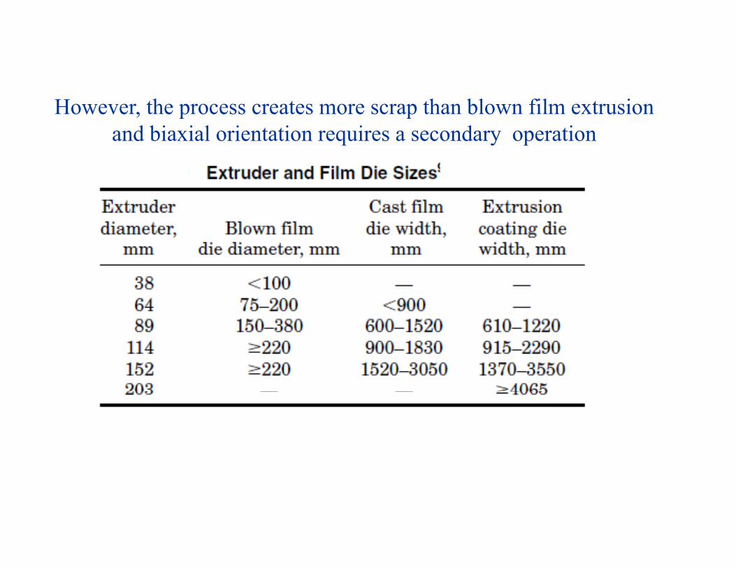
However the process creates more scrap than blown film extrusionHowever, the process creates more scrap than blown film extrusion and biaxial orientation requires a secondary operation
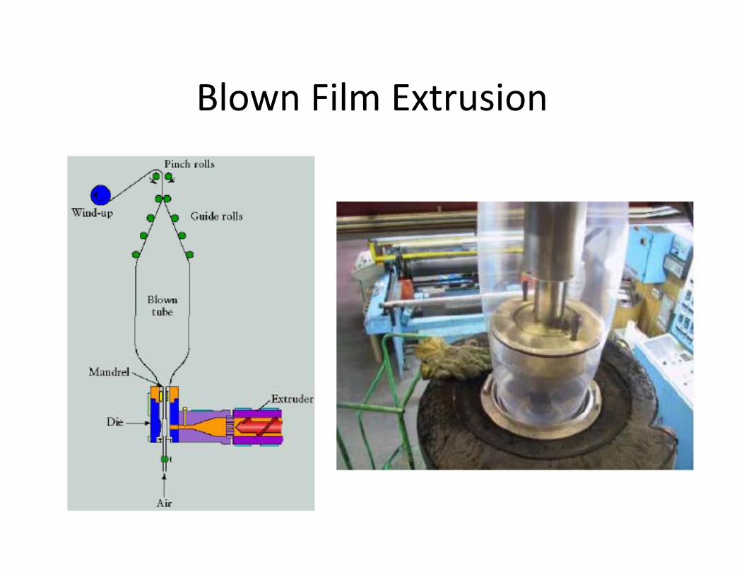
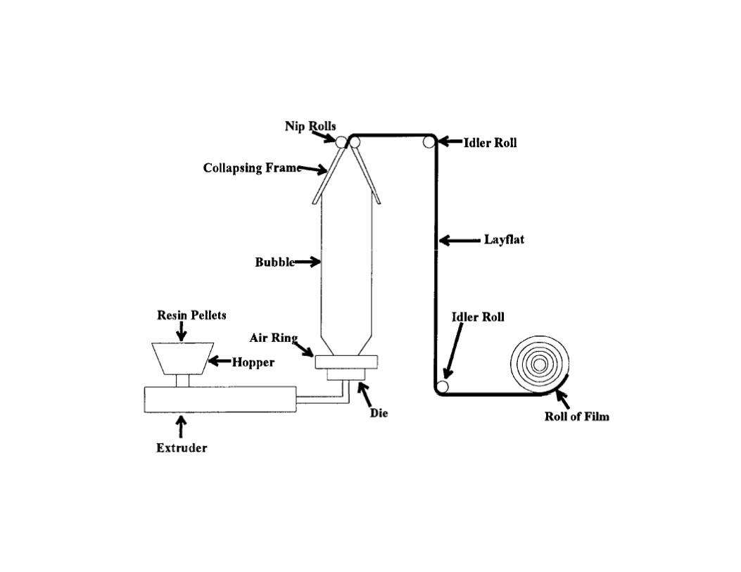
Blown Film ExtrusionBlown Film Extrusion
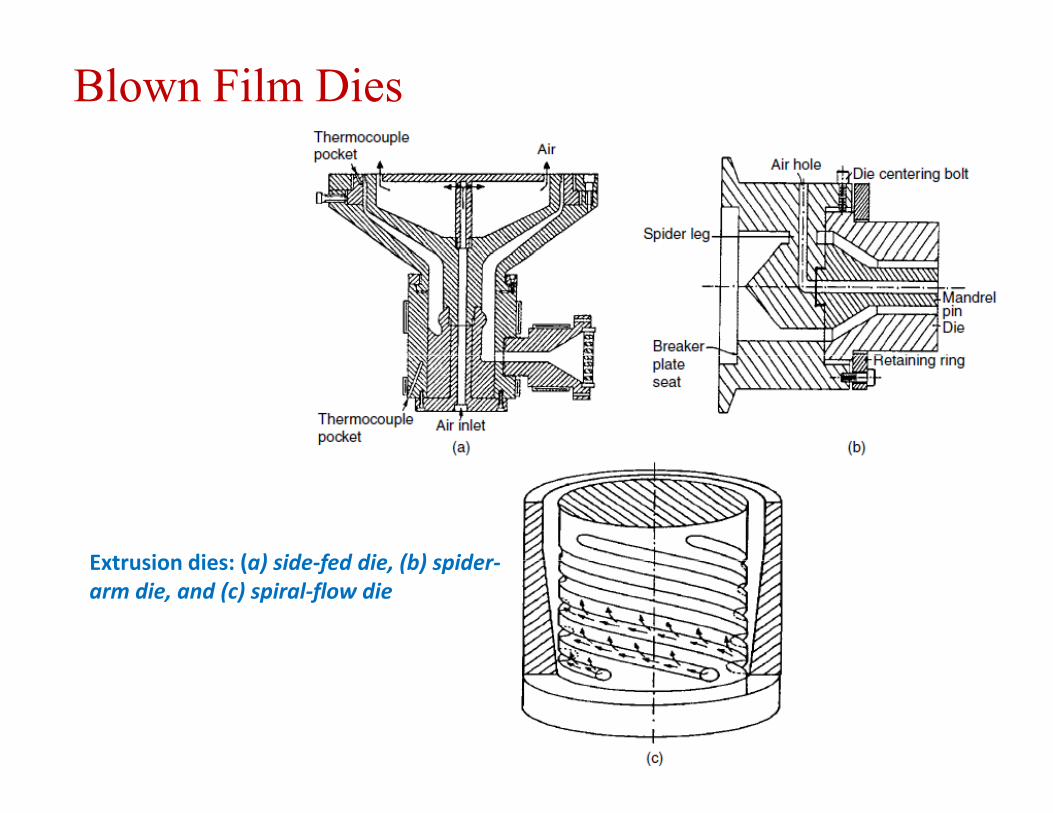
Blown Film Dies
Extrusion dies: (a) side fed die (b) spiderExtrusion dies: (a) side‐fed die, (b) spider‐arm die, and (c) spiral‐flow die
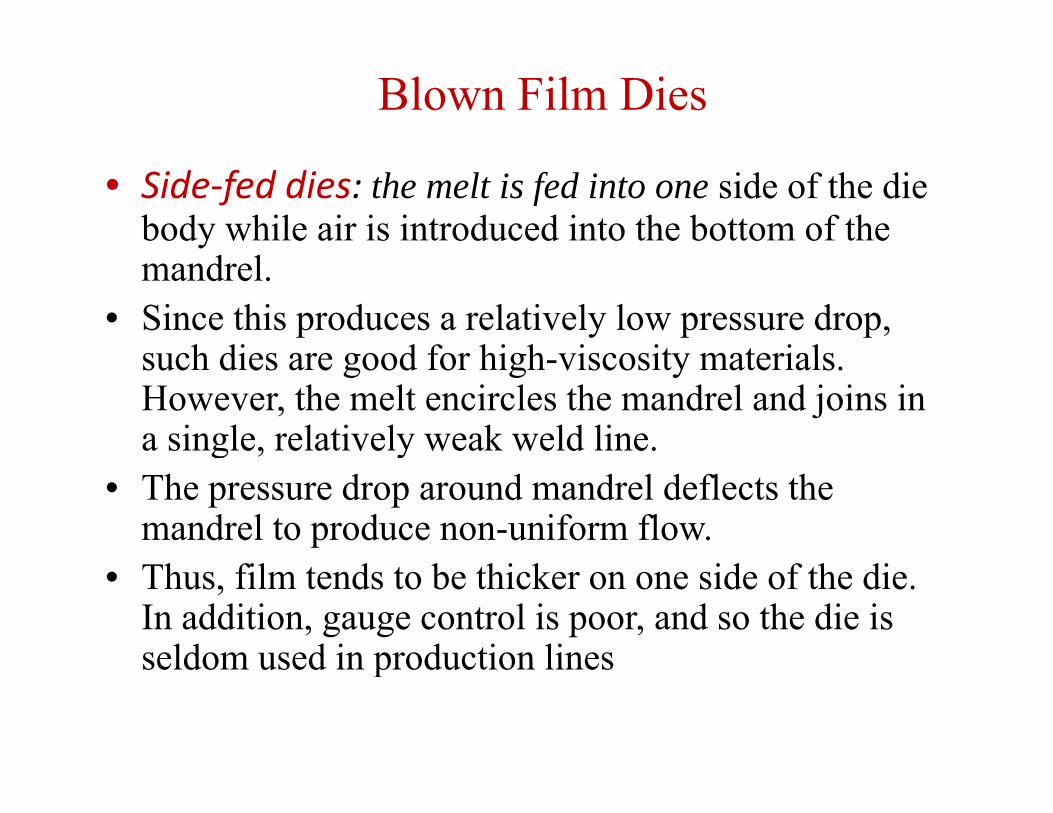
Blown Film Dies
• Side‐fed dies: the melt is fed into one side of the die body while air is introduced into the bottom of the mandrel.
• Since this produces a relatively low pressure drop, such dies are good for high viscosity materialssuch dies are good for high-viscosity materials. However, the melt encircles the mandrel and joins in a single, relatively weak weld line. g y
• The pressure drop around mandrel deflects the mandrel to produce non-uniform flow.
• Thus, film tends to be thicker on one side of the die. In addition, gauge control is poor, and so the die is seldom used in production linesseldom used in production lines
Blown Film Dies
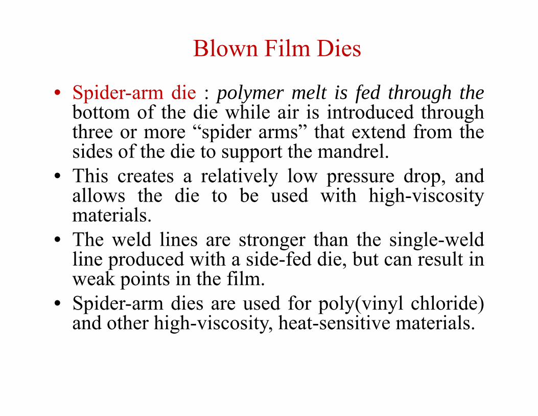
• Spider-arm die : polymer melt is fed through thebottom of the die while air is introduced throughthree or more “spider arms” that extend from thethree or more “spider arms” that extend from thesides of the die to support the mandrel.
• This creates a relatively low pressure drop, andThis creates a relatively low pressure drop, andallows the die to be used with high-viscositymaterials.Th ld li t th th i l ld• The weld lines are stronger than the single-weldline produced with a side-fed die, but can result inweak points in the film.p
• Spider-arm dies are used for poly(vinyl chloride)and other high-viscosity, heat-sensitive materials.
Blown Film Dies
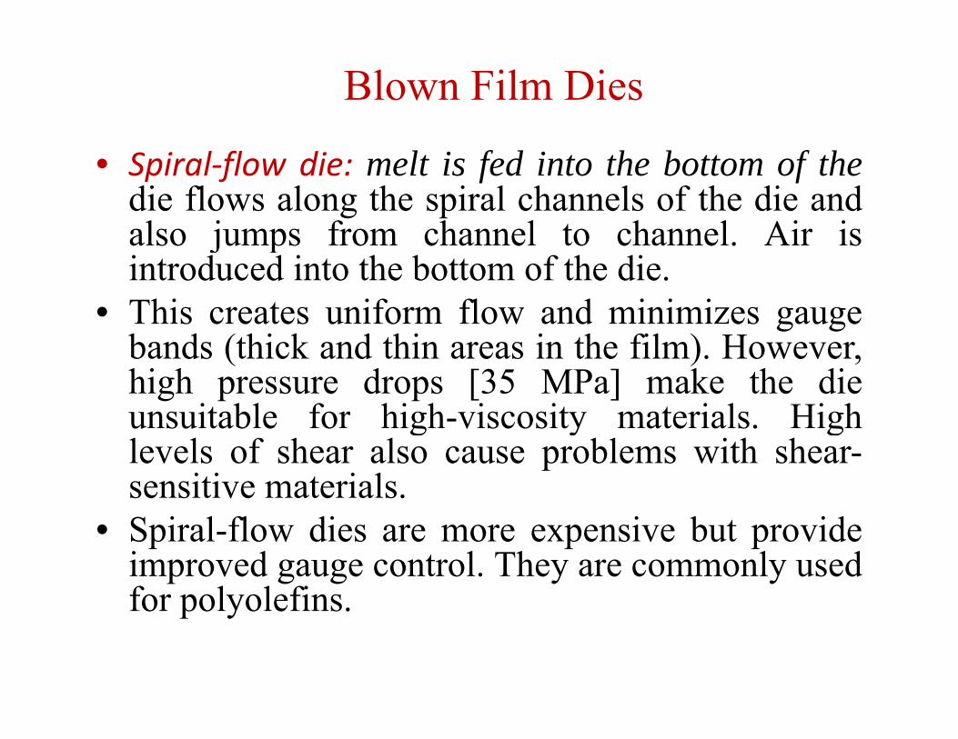
• Spiral‐flow die: melt is fed into the bottom of thedie flows along the spiral channels of the die andalso jumps from channel to channel Air isalso jumps from channel to channel. Air isintroduced into the bottom of the die.
• This creates uniform flow and minimizes gaugeThis creates uniform flow and minimizes gaugebands (thick and thin areas in the film). However,high pressure drops [35 MPa] make the dieunsuitable for high viscosity materials Highunsuitable for high-viscosity materials. Highlevels of shear also cause problems with shear-sensitive materials.
• Spiral-flow dies are more expensive but provideimproved gauge control. They are commonly usedfor polyolefinsfor polyolefins.
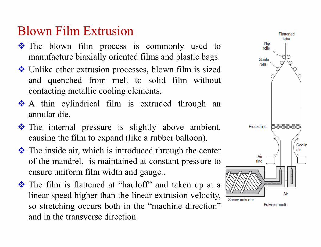
Blown Film Extrusion The blown film process is commonly used to The blown film process is commonly used to
manufacture biaxially oriented films and plastic bags. Unlike other extrusion processes, blown film is sized
d h d f l lid fil i hand quenched from melt to solid film withoutcontacting metallic cooling elements.
A thin cylindrical film is extruded through any gannular die.
The internal pressure is slightly above ambient,causing the film to expand (like a rubber balloon)causing the film to expand (like a rubber balloon).
The inside air, which is introduced through the centerof the mandrel, is maintained at constant pressure to
if fil idth densure uniform film width and gauge.. The film is flattened at “hauloff” and taken up at a
linear speed higher than the linear extrusion velocity,so stretching occurs both in the “machine direction”and in the transverse direction.