4-A DESIGN FOR TRUCKS - Georgia · PDF fileThe geometric design of an intersection is a...
27
1 Regulations for Driveway and Encroachment Control 4-1 CHAPTER 4 DESIGN CRITERIA The design of driveways shall comply with the guidelines of AASHTO ‟s A Policy on Geometric Design of Highways and Bridges , current edition. However, this chapter provides a summary of the minimum design constraints that will be checked during the plan review process. All modes of transportation should be taken into consideration, cars, pedestrians, bikes and trucks. The geometric design of an intersection is a collection of various elements - such as radius, width, grade, angle of intersection, etc, - that in combination provide for satisfactory operation of the vehicles that will use the intersection. Since the operating characteristics vary dramatically for different types of vehicles, the designer must first establish the design vehicle on which to base the design. The designer should also check the final design to ensure the design vehicles can operate satisfactorily. In addition, if the applicant can demonstrate that his design can accommodate the appropriate design vehicle even though one or more design elements do not meet the minimum values contained in this chapter, the Department may approve the plans. 4-A DESIGN FOR TRUCKS The design criteria given in this chapter have more stringent requirements for trucks. Even though the general use of such guidance would result in more desirable operations for all vehicles, it is neither practical nor necessary to design all facilities to accommodate trucks. The designer must use judgment in selecting the proper design vehicle. When semi trailer combination trucks are expected to use the intersection on a regular basis and in numbers more than just an occasional vehicle, then the intersection should be designed to accommodate the truck movements. This includes most driveways designed for industrial use and many commercial driveways. For commercial uses such as shopping centers, the preliminary site plan should indicate where heavy- duty pavement would be provided to accommodate truck access to loading docks. Any driveway associated with access/egress for the loading docks should use the truck radii. Minor movement driveways, particularly those that allow only right turns will generally only be used by passenger cars.
Transcript of 4-A DESIGN FOR TRUCKS - Georgia · PDF fileThe geometric design of an intersection is a...
1
Regulations for Driveway and Encroachment Control 4-1
CHAPTER 4
DESIGN CRITERIA
The design of driveways shall comply with the guidelines of AASHTO‟s A Policy on Geometric
Design of Highways and Bridges, current edition. However, this chapter provides a summary of the
minimum design constraints that will be checked during the plan review process. All modes of
transportation should be taken into consideration, cars, pedestrians, bikes and trucks.
The geometric design of an intersection is a collection of various elements - such as radius, width,
grade, angle of intersection, etc, - that in combination provide for satisfactory operation of the
vehicles that will use the intersection. Since the operating characteristics vary dramatically for
different types of vehicles, the designer must first establish the design vehicle on which to base the
design. The designer should also check the final design to ensure the design vehicles can operate
satisfactorily. In addition, if the applicant can demonstrate that his design can accommodate the
appropriate design vehicle even though one or more design elements do not meet the minimum
values contained in this chapter, the Department may approve the plans.
4-A DESIGN FOR TRUCKS
The design criteria given in this chapter have more stringent requirements for trucks. Even though the
general use of such guidance would result in more desirable operations for all vehicles, it is neither
practical nor necessary to design all facilities to accommodate trucks. The designer must use
judgment in selecting the proper design vehicle.
When semi trailer combination trucks are expected to use the intersection on a regular basis and in
numbers more than just an occasional vehicle, then the intersection should be designed to
accommodate the truck movements. This includes most driveways designed for industrial use and
many commercial driveways.
For commercial uses such as shopping centers, the preliminary site plan should indicate where heavy-
duty pavement would be provided to accommodate truck access to loading docks. Any driveway
associated with access/egress for the loading docks should use the truck radii. Minor movement
driveways, particularly those that allow only right turns will generally only be used by passenger
cars.

2
Regulations for Driveway and Encroachment Control 4-2
CHAPTER 4
DESIGN CRITERIA
4B DRIVEWAY WIDTH
When traffic impact studies are required (see Section 2D), the driveway shall be designed to provide
the number of lanes recommended in the study. Standard lane widths are 12‟.
When the need for multiple lanes is not established from a traffic impact study, the minimum and
maximum driveway widths are as set forth in Table 4-1.
DRIVEWAY USE WIDTH, FT
Minimum Maximum
CURRENT RESIDENTIAL GA STD. 14 20
CURRENT COMMERCIAL (ONE WAY) GA STD 16 20
CURRENT COMMERCIAL (TWO WAY) GA STD 24 40
MINING, LOGGING, FARMING, AGRICULTURAL 18 24
TABLE 4-1 DRIVEWAY WIDTHS
Note: When a traffic study indicates multiple lanes requiring greater widths, this table does not apply.
4C CORNER RADII
Corner radii are generally established by the minimum path of the inside wheels of the design vehicle
when making a right turn. The minimum corner radii to be used for driveways are given in Table 4-2.
The size of the radius is determined by the development use typical design vehicle.
DRIVEWAY USE MINIMUM RADIUS, FT
RESIDENTIAL 15
COMMERCIAL 35
WHEN DESIGNED FOR TRUCKS 75
TABLE 4-2 MINIMUM CORNER RADII

3
Regulations for Driveway and Encroachment Control 4-3
CHAPTER 4
DESIGN CRITERIA
4D LEFT TURNING CONTROL RADII
The path of the inside wheels during left turns is also important for the design of median openings
and intersections with dual left turn lanes. Table 4-3 contains guidelines for minimum left turning
radii.
DRIVEWAY USE Control Radius, Ft
RESIDENTIAL 40
COMMERCIAL 50
TABLE 4-3 LEFT TURNING CONTROL RADIUS
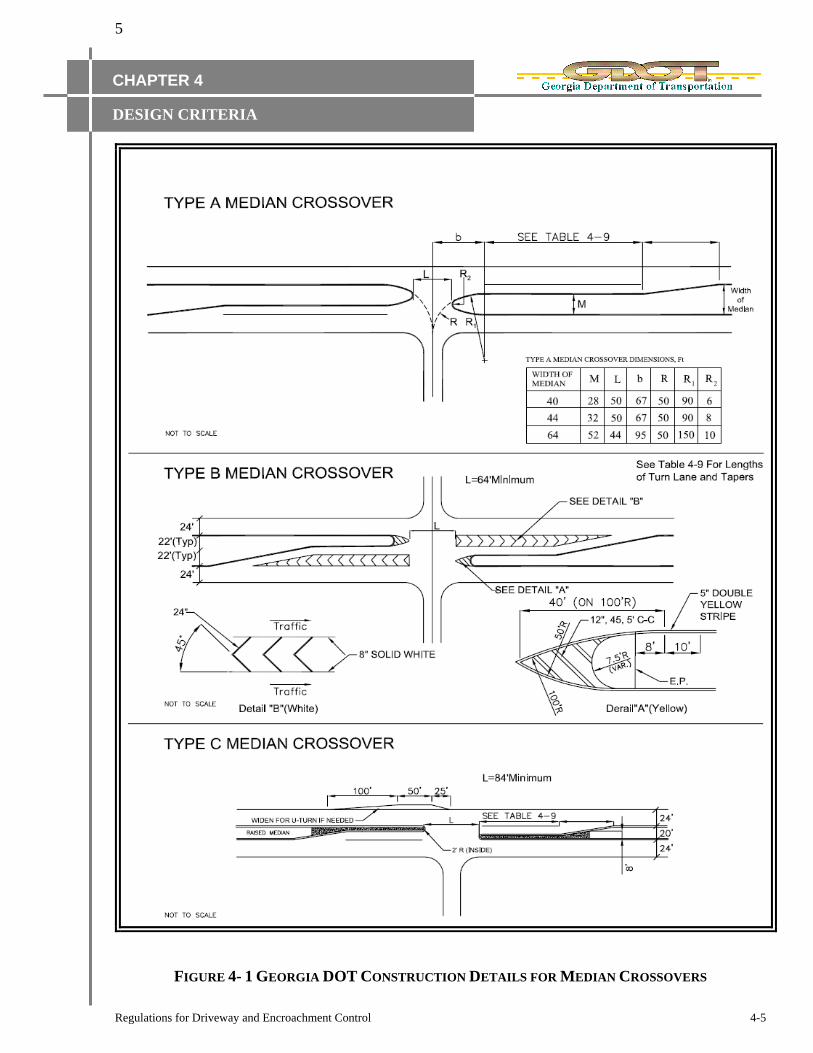
4E MEDIAN CROSSOVER DESIGN
Driveways onto Divided State Highways where full access is to be provided shall be designed in
accordance with Georgia DOT Construction Details for Median Crossovers. The detail has three
types of designs (See Figure 4-1) that are applicable in different situations.
4E-1 TYPE A MEDIAN CROSSOVER
Type A median crossovers may be considered on low volume rural roadways. This type of median
crossover is only allowed when the projected volume of left turning vehicles does not exceed 20 per
hour per direction.

4
Regulations for Driveway and Encroachment Control 4-4
CHAPTER 4
DESIGN CRITERIA
4E-2 TYPE B MEDIAN CROSSOVER
Type B median crossovers are required when the projected volume of the left turn movement exceeds
20 vehicles per hour per direction and/or when the median width is sufficient to offset the left turn
lane from the adjacent through lane. This design provides better sight distance for vehicles in the left
turn lane. This is important for unsignalized intersections and when unprotected turns are allowed at
signalized intersections.
4E-3 TYPE C MEDIAN CROSSOVER
Type C median crossovers are typically used in urban areas where the median width is limited to
approximately 24‟ or less. With this type of crossover, it may be necessary to add pavement to the
opposite edge in order to accommodate U-Turns.
Table 4-4 illustrates the minimum pavement width that is required for some vehicles to make U-
Turns. The required width is given for passenger cars and for WB-50 trucks.
DRIVEWAY USE MINIMUM WIDTH (W), FT
PASSENGER CAR 48
WB - 50 TRUCK 90
TABLE 4-4 MINIMUM ROAD WIDTH FOR U-TURNS
5
Regulations for Driveway and Encroachment Control 4-5
CHAPTER 4
DESIGN CRITERIA
FIGURE 4- 1 GEORGIA DOT CONSTRUCTION DETAILS FOR MEDIAN CROSSOVERS

6
Regulations for Driveway and Encroachment Control 4-6
CHAPTER 4
DESIGN CRITERIA
4F HORIZONTAL ALIGNMENT In general, the horizontal alignment of driveways should be designed using a tangent section from the
centerline of the State Highway and extending to the property line. Horizontal curves that are used
outside the State Highway Right of Way are generally not part of the permit issued by the
Department.
Horizontal curves should be sufficient to provide safe operations at speeds that would normally occur
in the areas where they are constructed.
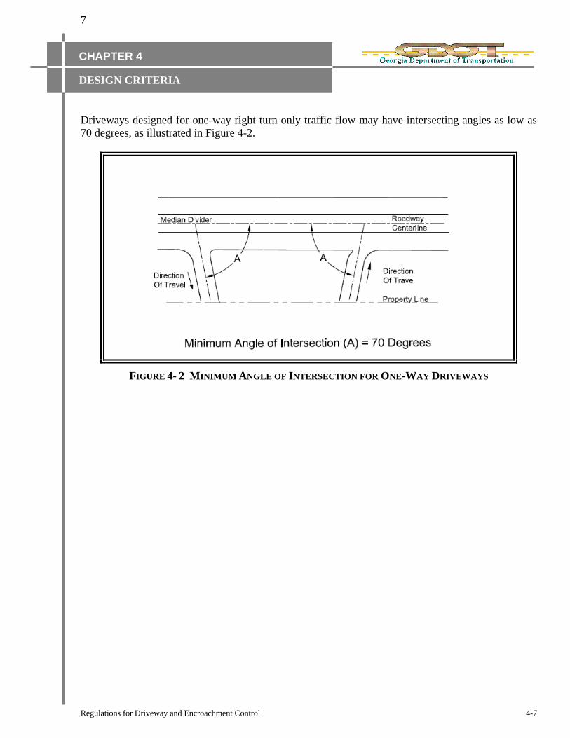
4F-1 ANGLE OF INTERSECTION
Intersecting driveways and roads should generally meet at or nearly at right angles. Driveways and
roads intersecting at acute angles create sight limitations that should be avoided.
In some cases, a more suitable overall design can be achieved by allowing intersecting angles other
than 90 degrees. Table 4-5 gives the minimum angle of intersection that will generally be allowed for
driveways designed to accommodate two-way traffic flow. Figure 4-2 illustrates the minimum angle
of intersection for one-way right turn only driveways.
4F-2 ALIGNMENT OF APPROACH AND DEPARTURE LANES
Driveways should be designed and constructed so as to align with driveways or streets on the
opposite side of the highway. The alignment of through movements crossing the highway should be
such that abrupt shifts in the travel pattern are not required.
DRIVEWAY USE Minimum Angle of Intersection (A), Degrees
Residential 70
Commercial 85
When Designed for Trucks 88
TABLE 4-5 MINIMUM ANGLE OF INTERSECTION FOR TWO-WAY DRIVEWAYS
7
Regulations for Driveway and Encroachment Control 4-7
CHAPTER 4
DESIGN CRITERIA
Driveways designed for one-way right turn only traffic flow may have intersecting angles as low as
70 degrees, as illustrated in Figure 4-2.
FIGURE 4- 2 MINIMUM ANGLE OF INTERSECTION FOR ONE-WAY DRIVEWAYS

8
Regulations for Driveway and Encroachment Control 4-8
CHAPTER 4
DESIGN CRITERIA
4G DRIVEWAY TIE-IN CONFIGURATIONS
4G-1 DRIVEWAY CONNECTIONS TO URBAN SECTIONS
This section describes the requirements for constructing driveway connections to State Highways
with curb and gutter. Georgia DOT has two Standard Detail Drawings (A1 and A2) that describe the
appropriate design and construction methods for these conditions. The basic layout of the two
configurations is schematically shown in Figure 4-3.
FIGURE 4-3 DRIVEWAY CONNECTIONS TO URBAN SECTIONS

9
Regulations for Driveway and Encroachment Control 4-9
CHAPTER 4
DESIGN CRITERIA
Note: Please use the current ADA requirements when applying Figure 4-3. Only use GDOT
Construction Detail A-1for Residential Driveways. Connections shown in Standard 9031J
Construction Detail A2 are commonly used for commercial driveways, while the configuration given
in Construction Detail A-1 is typically used for residential driveways. Figure 4-3 is a simplified
diagram of the details. The designer should refer to the actual GDOT Construction Details when
preparing driveway plans for the most current standards.
The actual dimensions of lane widths, radii, etc. should be as specified in relevant sections of this
document. Figure 4-3 also does not show deceleration or turn lanes. See section 4I for guidelines on
deceleration lane requirements and their dimensions.
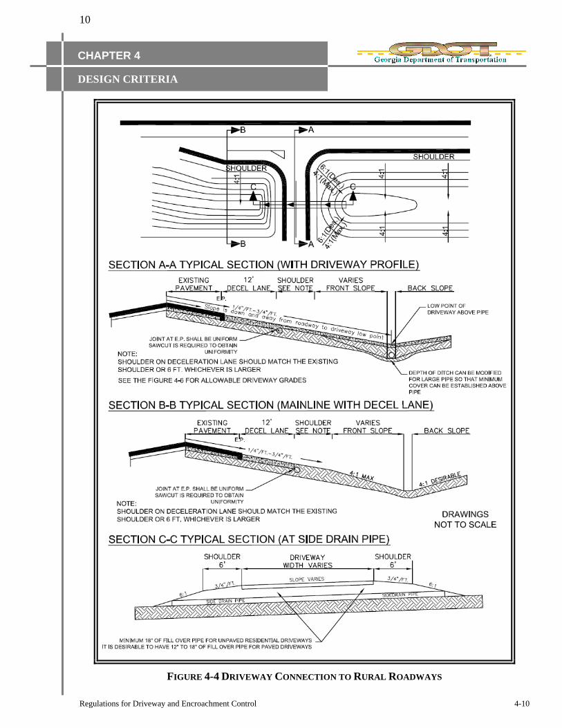
4G-2 DRIVEWAY CONNECTIONS TO RURAL SECTIONS
The section describes the requirements for connecting to State Highways that do not have curb and
gutter.
The basic configuration and requirements for connecting a driveway that will not have curb and
gutter into a State Highway that also does not have curb and gutter are illustrated in Figure 4-4.
The ends of the driveway pipe should be extended to maintain a minimum six (6) feet shoulder. The
side slope should normally be less than 6:1 but shall be no greater than 4:1.
When ditches are constructed on the State Right-of-Way, the front slope should be no greater than
4:1. When the bottom of the ditch is between 5‟ and 8‟ below the edge of pavement, the front slope
can be increased to 3:1. When the ditch is greater than 8‟ below the edge of pavement, the front slope
can be increased to 2:1. In any case, when the front slope is greater than 4:1, guardrail should be
used.
Figure 4-4 shows a deceleration lane, which in some conditions is not required. See section 4I to
determine if a deceleration lane will be required.
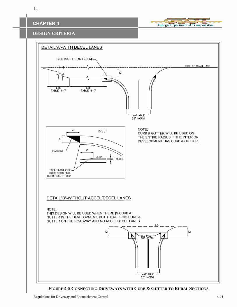
For connecting a driveway that will have curb and gutter to a State Highway without curb and gutter,
see Figure 4-5.
Curb and gutter should not be used adjacent to a travel lane on a road with posted speed limits above
45 MPH. A 4” mountable curb and gutter may be used along acceleration/deceleration lanes or a
designated turn lane but not along the taper.
10
Regulations for Driveway and Encroachment Control 4-10
CHAPTER 4
DESIGN CRITERIA
FIGURE 4-4 DRIVEWAY CONNECTION TO RURAL ROADWAYS
11
Regulations for Driveway and Encroachment Control 4-11
CHAPTER 4
DESIGN CRITERIA
FIGURE 4-5 CONNECTING DRIVEWAYS WITH CURB & GUTTER TO RURAL SECTIONS

12
Regulations for Driveway and Encroachment Control 4-12
CHAPTER 4
DESIGN CRITERIA
4H DRIVEWAY GRADES
In general, the grade of the driveway should be a continuation of the cross slope of the roadway that
it connects to. Figure 4-6 illustrates allowable grades for driveways connecting to State Highways.
Figure 4-6 (A) shows the profile of a driveway connecting to the normal cross section of a highway.
The cross slope of the highway should be maintained for a minimum distance of 12‟ beyond the edge
of pavement.
Where the roadway pavement is super elevated, it is desirable to reduce the grade of the driveway
below that of the super elevated pavement in order to reduce the amount of water draining across the
highway. The grade of the driveway will be allowed to break at the edge of pavement. However, the
difference in grade change must not exceed 0.08ft/ft., and be in accordance with Georgia Standard
9028C or current standard. See Figure 4-6 for a brief overview of this standard.
FIGURE 4-6 ALLOWABLE DRIVEWAY GRADES

13
Regulations for Driveway and Encroachment Control 4-13
CHAPTER 4
DESIGN CRITERIA
4I AUXILIARY TURN LANES
4I-1 WHEN DECELERATION LANES ARE REQUIRED
The provisions of this section shall generally apply to auxiliary lanes installed on the approach to an
intersection that provide for deceleration and storage of vehicles waiting to turn right or left. Such
lanes are always beneficial and will be required in conjunction with commercial driveway permits
when projected traffic volumes exceed minimum levels as provided in the sections below.
All existing utilities which would be under new pavement or in acceleration/deceleration lanes shall
be relocated before final grading and paving, and at no cost to DOT. Existing utilities which are
found to be not in conflict with construction, may be allowed if a Retention Request is processed by
the utility owner and approved by the Department.
4I-1-1 Minimum Requirements for Right Turn Deceleration Lanes
Right turn deceleration lanes must be constructed at no cost to the Department if the daily site
generated Right Turn Volumes (RTV) based on ITE Trip Generation (assuming a reasonable
distribution of entry volumes) meet or exceed the values shown in Table 4-6. Passing lane sections
fall under the criteria for two or more lanes.
POSTED SPEED 2 LANE ROUTES MORE THAN 2 LANES ON MAIN ROAD
AADT AADT
< 6000 >=6000 <10000 >=10000
35 MPH OR LESS 200 RTV a day 100 RTV a day 200 RTV a day 100 RTV a day
40 TO 50 MPH 150 RTV a day 75 RTV a day 150 RTV a day 75 RTV a day
55 TO 60 MPH 100 RTV a day 50 RTV a day 100 RTV a day 50 RTV a day
>= 65 MPH Always Always Always Always
TABLE 4-6 MINIMUM VOLUMES REQUIRING RIGHT TURN LANES
In the event the District Access Management Engineer determines that field conditions or other
factors indicate that it would be in the best interest of the Department to waive the decel lane
requirement, the District Access Management Engineer must document the recommendations using
the form in Appendix E. The recommendations shall be approved by the District Engineer and be
attached to the Permit. The District Access Management Engineer may also require the addition of a
Right Turn lane, even when the conditions in Table 4-6 are not met, if roadway geometry or field
conditions indicate that the safety of the traveling public would be improved. The recommendation
must be documented and approved by the District Engineer for inclusion with the Permit.
The R/W for accel/decel lanes may be dedicated in fee simple to the Department for the Department
to maintain or the applicant must sign an agreement with the Department to maintain the lane to the
Department‟s standards and to hold harmless the Department in the event that section of roadway is
identified in any liability action. A Limited Warranty Deed is not acceptable when R/W is donated to
the Department.
14
Regulations for Driveway and Encroachment Control 4-14
CHAPTER 4
DESIGN CRITERIA
The pavement specifications for accel/decel lanes must be Georgia DOT Standard Specifications for
Construction of Roads and Bridges, or be as described and approved by the Chief Engineer in cases
where a lesser design may be acceptable, or where a proposed project is expected to tie in.
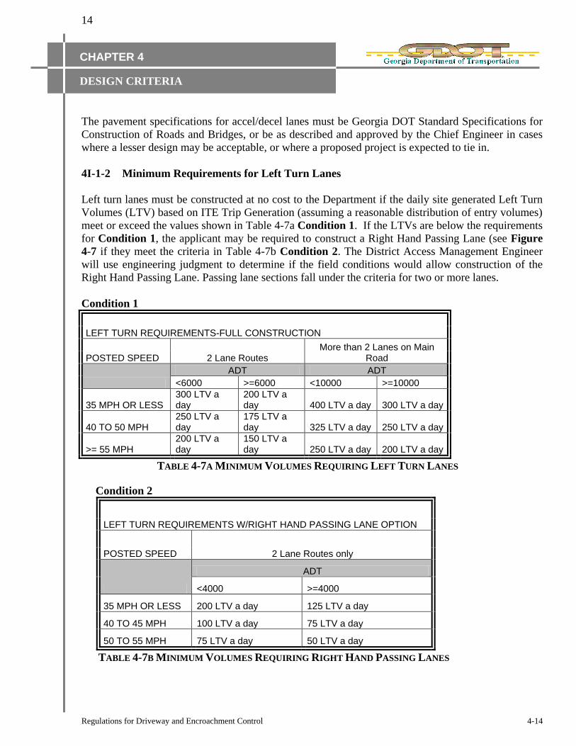
4I-1-2 Minimum Requirements for Left Turn Lanes
Left turn lanes must be constructed at no cost to the Department if the daily site generated Left Turn
Volumes (LTV) based on ITE Trip Generation (assuming a reasonable distribution of entry volumes)
meet or exceed the values shown in Table 4-7a Condition 1. If the LTVs are below the requirements
for Condition 1, the applicant may be required to construct a Right Hand Passing Lane (see Figure
4-7 if they meet the criteria in Table 4-7b Condition 2. The District Access Management Engineer
will use engineering judgment to determine if the field conditions would allow construction of the
Right Hand Passing Lane. Passing lane sections fall under the criteria for two or more lanes.
Condition 1
LEFT TURN REQUIREMENTS-FULL CONSTRUCTION
POSTED SPEED 2 Lane Routes More than 2 Lanes on Main
Road
ADT ADT
<6000 >=6000 <10000 >=10000
35 MPH OR LESS 300 LTV a day
200 LTV a day 400 LTV a day 300 LTV a day
40 TO 50 MPH 250 LTV a day
175 LTV a day 325 LTV a day 250 LTV a day
>= 55 MPH 200 LTV a day
150 LTV a day 250 LTV a day 200 LTV a day
TABLE 4-7A MINIMUM VOLUMES REQUIRING LEFT TURN LANES
Condition 2
LEFT TURN REQUIREMENTS W/RIGHT HAND PASSING LANE OPTION
POSTED SPEED 2 Lane Routes only
ADT
<4000 >=4000
35 MPH OR LESS 200 LTV a day 125 LTV a day
40 TO 45 MPH 100 LTV a day 75 LTV a day
50 TO 55 MPH 75 LTV a day 50 LTV a day
TABLE 4-7B MINIMUM VOLUMES REQUIRING RIGHT HAND PASSING LANES

15
Regulations for Driveway and Encroachment Control 4-15
CHAPTER 4
DESIGN CRITERIA
EXISTING R/W
EXISTING R/W
EXISTING R/W
EXISTING R/W
EX
IST
ING
R/W
EX
IST
ING
R/W
5" DOUBLE YELLOW (INSTALL TYPE 1 RPM'S)
5" WHITE MINI SKIP 2' STRIPE 6' GAPS
5" SOLID WHITE STRIPE
5" WHITE MINI SKIP 2' STRIPE 6' GAPS
INSTALL DELINEATORS 25' SPACING
5" WHITE MINI SKIP 2' STRIPE 6' GAPS
100' TAPER 100' TAPER
REQ'D
THERMOPLASTIC
TRAFFIC STRIPING
WHITE, DETAIL A
INSTALL
TYPE 2 RPM'S REQ'D
THERMOPLASTIC
TRAFFIC STRIPING
WHITE, DETAIL C
CO
MM
ER
CIA
L D
RIV
E
INSTALL
TYPE 2 ARROWS
INSTALL
TYPE 2 RPM'S
STATE ROUTE
100' MINIMUM
EXAMPLE ONLY
APPENDIX F
FIGURE 4-7 RIGHT HAND PASSING LANE
In the event the District Access Management Engineer determines that field conditions or other
factors indicate that it would be in the best interest of the Department to waive the left turn lane
requirement, the District Access Management Engineer must document the recommendations using
the form in Appendix E. The recommendations shall be approved by the District Engineer and be
attached to the Permit. The District Access Management Engineer may also require the addition of a
Left Turn lane, even when the conditions in Table 4-7 are not met, if roadway geometry or field
conditions indicate that the safety of the traveling public would be improved. The recommendation
must be documented and approved by the District Engineer for inclusion with the Permit.
4I-2 RIGHT TURN LANE LENGTHS
This section provides the design guidelines that should be used to establish the lengths of turn lanes if
they are required under the provisions of the previous section.
Under ideal conditions, turn lanes should provide a full-width lane that is long enough to allow for
vehicles to decelerate from the operating speed to a full stop in addition to the length of full-width
lane that is needed to store vehicles waiting to turn.
Table 4-8 contains guidelines for lengths of tapers and full-width turn lanes. The taper length in Table
4-8 applies to deceleration right turn lanes only. Guidelines for left turn tapers and lengths are given
in Section 4I-4.

16
Regulations for Driveway and Encroachment Control 4-16
CHAPTER 4
DESIGN CRITERIA
SPEED, MPH FULL WIDTH STORAGE, FT TAPER, FT
25 50
30 75 50
35 100 50
40 150 50
45 175 100
50 225 100
55 250 100
60 300 100
65 350 100
TABLE 4-8 MINIMUM RIGHT TURN DECELERATION LENGTHS
When traffic studies are conducted, the length of full-width lane needed for storage should be
determined. If the length of full-width storage is greater than the length of full-width storage shown
in Table 4-8, the longer length should be provided.
At signalized intersections, the amount of storage for both right and left turns can be based on the
number of vehicles arriving during 1.5 signal cycles.
For unsignalized intersections, a commonly used rule of thumb is that left turn storage should
accommodate vehicles arriving during a two-minute period. Minimal storage is required for right turn
lanes at unsignalized intersections.
4I-3 ACCELERATION LANES
Acceleration lanes are generally not provided on low speed highways. Acceleration lanes may be
required at locations where grade, sight distance or traffic is such that the Department determines
they are needed. When operating speeds on the highway are 55 MPH and above, full-width
acceleration lanes designed to meet the AASHTO minimum length should be considered.

17
Regulations for Driveway and Encroachment Control 4-17
CHAPTER 4
DESIGN CRITERIA
4I-4 LEFT TURN LANE DESIGN
The design of left turn lanes should consider the intended function and the characteristics of the
highway. In many cases, it is necessary to widen the existing roadway to introduce the left turn lane.
All vehicles approaching the turn lane are shifted to the right. The left turning traffic is then shifted
back into the lane. Through traffic is returned to its original lane beyond the intersection. When the
highway has a median that is at least 20 feet wide, the left turn lane can be developed out of the
median, avoiding the need for transitions.
The basic design elements of left turn lanes are illustrated in Table 4-9. This example shows
symmetrical widening, which basically requires the through traffic on each side to shift by one half of
the lane width. Some circumstances may dictate that all widening be achieved on one side, which
requires a full lane shift for through traffic on the side where the additional width is developed. Table
4-9 provides guidelines for selecting the proper length of approach taper.
POSTED
SPEED LIMIT, MPH
APPROACH AND DEPARTURE TAPER, FT BAY TAPER, FT FULL WIDTH STORAGE
6’ Shift 12’ Shift
30 90 180 50 135
35 125 250 50 160
40 160 320 50 210
45 270 540 100 235
50 300 600 100 285
55 330 660 100 310
60 360 720 100 360
65 390 780 100 410
TABLE 4-9 MINIMUM DESIGN ELEMENTS OF LEFT TURN LANES

18
Regulations for Driveway and Encroachment Control 4-18
CHAPTER 4
DESIGN CRITERIA
The example shown in Table 4-9 has straight-line tapers. These are acceptable but other designs may
also be used, including the following: partial tangent tapers, symmetrical reverse curve, and
asymmetrical reverse curve. See latest edition of AASHTO green book for details.
The required length of full-width storage is based on the peak hour traffic volumes. This should be
determined in the traffic study. The amount of storage is dependent on the type of traffic control in
effect. For signalized intersections, the storage should be sufficient to accommodate the number of
vehicles arriving during 1.5 signal cycles, using peak hour volumes. At stop-controlled intersections,
the storage is typically based on the number of vehicles arriving during a two-minute period within
the peak hour.
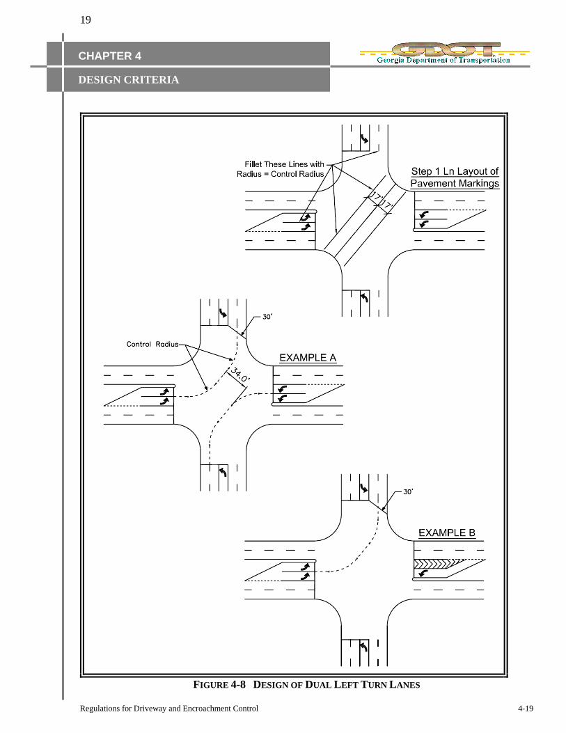
4I-5 DUAL LEFT TURN LANES
Dual left turn lanes are often needed to satisfy high volume demands. Capacity analysis should be
used to identify the need for dual left turn lanes. Dual left turn lanes are typically considered when
the peak hour left turn volume is 300 vehicles or greater.
The decision to use dual left turn lanes should consider the off-peak periods as well as the peak
periods. The off-peak periods may be adversely affected, since the use of dual left turn lanes typically
precludes permissive left turns.
If dual left turn lanes are included in the design, the following design guidelines should be
considered:
Because of off tracking and the added difficulty involving two-abreast turns, a minimum 30‟
throat-width should be provided through the intersection.
Pavement markings should be provided to guide the path of the turning vehicles.
The design should be checked to ensure that conflicts are minimized between opposing left
turn maneuvers. Figure 4-8, Example “A” shows the layout of marking for opposing dual left
turn lanes. This layout provides an additional 10‟ of width for the inside left turns to pass.
When dual left turn lanes are located opposite from an approach that does not have a dual left
turn lane, the design should minimize the lateral offset for vehicles traveling straight through
the intersection. This can be accomplished by providing a median or striped-out area opposite
the dual left turn lane. See Figure 4-8, Example “B”.
19
Regulations for Driveway and Encroachment Control 4-19
CHAPTER 4
DESIGN CRITERIA
FIGURE 4-8 DESIGN OF DUAL LEFT TURN LANES

20
Regulations for Driveway and Encroachment Control 4-20
CHAPTER 4
DESIGN CRITERIA
4J RAISED ISLANDS
Islands are an important form of intersection channelization that is often needed to accomplish the
following objectives:
Prohibit undesirable movements,
Define the paths of allowed movements, and
Provide a refuge area for pedestrians.
Painted lines are an effective means to direct the paths of vehicular movement. However, raised
islands are more effective during times when visibility is reduced. When islands are to serve as
pedestrian refuge areas, they should be constructed as raised islands.
Raised islands should be large enough to command attention and accommodate wheelchairs. The
smallest raised island should have an area of 75 square feet. However, 100 square feet or more is
desirable. (Refer to revised ADA standards)
When multiple crosswalks are required to pass through islands, the required size may exceed the 100
square feet mentioned above. The additional area may be required to install wheelchair ramps. As an
alternate to ramps, the pedestrian travel way can be “slotted” through the island, remaining on the
grade of the roadway.
Figure 4-9 shows a typical design for a raised corner island at a two-lane driveway. This design uses
a radius of 65‟ and provides an island of sufficient size for wheelchair ramps and level landings.
Figure 4-9 also contains a median island along the driveway. This drawing should not imply that
median islands or corner islands are required for all driveways. However, large painted islands may
not serve the intended channelization purpose and the type island to be used should be based on the
actual circumstances of the site.
Raised islands should be offset from the edge of the adjacent travel lane on all sides. The amount of
offset shall be 4‟ desirable, 2„ minimum. When raised islands are adjacent to highways with posted
speed limits above 45 MPH, the island shall be offset from the edge of the highway by a minimum
distance of 10‟.
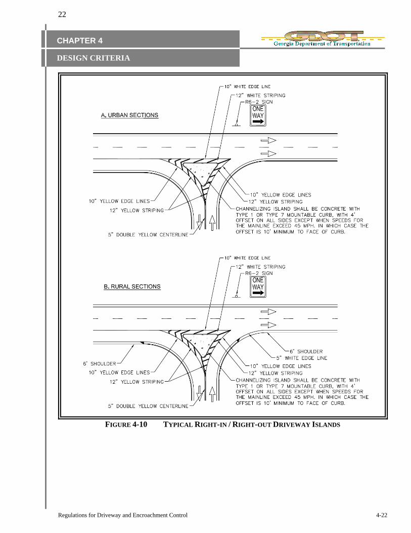
4J-1 RIGHT-IN / RIGHT-OUT DRIVEWAYS
Raised islands are also typically used to channelize the movements at a driveway where only right
turns are allowed. The raised island is an effective means of preventing left turns. Figure 4-10
provides a typical design for right turn only islands. All sign posts to be placed within concrete area
must have hole through pavement structure. The hole may be either formed, drilled or sawed.
A center raised concrete median shall be placed on the State Route in conjunction with the
construction of a right in/right out driveway in the event the District Access Management Engineer
determines that field conditions or other factors indicate the need for such median to help prevent left
turn movements at the driveway.

21
Regulations for Driveway and Encroachment Control 4-21
CHAPTER 4
DESIGN CRITERIA
FIGURE 4-9 DESIGN OF RAISED ISLANDS
22
Regulations for Driveway and Encroachment Control 4-22
CHAPTER 4
DESIGN CRITERIA
FIGURE 4-10 TYPICAL RIGHT-IN / RIGHT-OUT DRIVEWAY ISLANDS

23
Regulations for Driveway and Encroachment Control 4-23
CHAPTER 4
DESIGN CRITERIA
4K PEDESTRIAN CONSIDERATIONS
When driveways are constructed in areas where pedestrian activity is not prohibited, the design
should adequately provide for pedestrian movement and interaction with vehicular traffic. Pedestrian
features that should be considered include sidewalks, crosswalks, traffic control features, and curb
ramps are required. The Americans With Disabilities Act Accessibility Guidelines must be utilized
where pedestrian traffic is expected.
Figure 4-11 contains typical locations for curb cut ramps. Ramps are required at all pedestrian
crosswalks where curb is constructed or replaced.
The required crosswalk detail is also shown in Figure 4-11. See current Department Construction
Details for the appropriate treatment. Refer to Pedestrian & Streetscape Guide.
Figure 4-12 contains typical locations for ramps in raised concrete traffic islands.
4L PAVEMENT DESIGN
All construction, within the right of way, of surfaces intended for travel by motorized vehicles shall
be paved.
The pavement specification of auxiliary lanes on State Highways shall be the Georgia DOT
Pavement Design, or the typical of the existing roadway, whichever is less.

24
Regulations for Driveway and Encroachment Control 4-24
CHAPTER 4
DESIGN CRITERIA
FIGURE 4-11 TYPICAL CROSSWALK DETAILS

25
Regulations for Driveway and Encroachment Control 4-25
CHAPTER 4
DESIGN CRITERIA
FIGURE 4-12 RAISED CONCRETE ISLAND WITH RAMPS
(SEMI-DEPRESSED)
26
Regulations for Driveway and Encroachment Control 4-26
CHAPTER 4
DESIGN CRITERIA
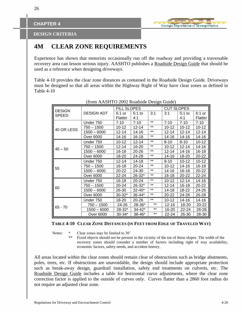
4M CLEAR ZONE REQUIREMENTS
Experience has shown that motorists occasionally run off the roadway and providing a traversable
recovery area can lesson serious injury. AASHTO publishes a Roadside Design Guide that should be
used as a reference when designing driveways.
Table 4-10 provides the clear zone distances as contained in the Roadside Design Guide. Driveways
must be designed so that all areas within the Highway Right of Way have clear zones as defined in
Table 4-10
(from AASHTO 2002 Roadside Design Guide)
DESIGN SPEED
DESIGN ADT
FILL SLOPES CUT SLOPES
6:1 or Flatter
5:1 to 4:1
3:1 3:1 5:1 to 4:1
6:1 or Flatter
40 OR LESS
Under 750 7-10 7-10 ** 7-10 7-10 7-10
750 – 1500 10-12 12-14 ** 10-12 10-12 10-12
1500 – 6000 12-14 14-16 ** 12-14 12-14 12-14
Over 6000 14-16 16-18 ** 14-16 14-16 14-16
45 – 50
Under 750 10-12 12-14 ** 8-10 8-10 10-12
750 – 1500 12-14 16-20 ** 10-12 12-14 14-16
1500 – 6000 16-18 20-26 ** 12-14 14-16 16-18
Over 6000 18-20 24-28 ** 14-16 18-20 20-22
55
Under 750 12-14 14-18 ** 8-10 10-12 10-12
750 – 1500 16-18 20-24 ** 10-12 14-16 16-18
1500 – 6000 20-22 24-30 ** 14-16 16-18 20-22
Over 6000 22-24 26-32* ** 16-18 20-22 22-24
60
Under 750 16-18 20-24 ** 10-12 12-14 14-16
750 – 1500 20-24 26-32* ** 12-14 16-18 20-22
1500 – 6000 26-30 32-40* ** 14-18 18-22 24-26
Over 6000 30-32* 36-44* ** 20-22 24-26 26-28
65 - 70
Under 750 18-20 20-26 ** 10-12 14-16 14-16
750 – 1500 24-26 28-36* ** 12-16 18-20 20-22
1500 – 6000 28-32* 34-42* ** 16-20 22-24 26-28
Over 6000 30-34* 38-46* ** 22-24 26-30 28-30
TABLE 4-10 CLEAR ZONE DISTANCES (IN FEET FROM EDGE OF TRAVELED WAY)
Notes: * Clear zones may be limited to 30‟
** Fixed objects should not be present in the vicinity of the toe of these slopes. The width of the
recovery zones should consider a number of factors including right of way availability,
economic factors, safety needs, and accident history.
All areas located within the clear zones should remain clear of obstructions such as bridge abutments,
poles, trees, etc. If obstructions are unavoidable, the design should include appropriate protection
such as break-away design, guardrail installation, safety end treatments on culverts, etc. The
Roadside Design Guide includes a table for horizontal curve adjustments, where the clear zone
correction factor is applied to the outside of curves only. Curves flatter than a 2860 foot radius do
not require an adjusted clear zone.
27
Regulations for Driveway and Encroachment Control 4-27
CHAPTER 4
DESIGN CRITERIA
4N RIGHT OF WAY REQUIREMENTS
In order to construct driveways, it is often necessary to construct improvements to the State Highway.
These improvements typically include the addition of lanes along the State Highway such as a
deceleration lane, or traffic signal equipment.
If sufficient right of way exists, improvements to the State Highway will be permitted without the
requirement of additional right of way. In urban sections, the face of curb along the State Highway
should be no closer than 14‟ from the right of way. In rural sections, the point located one-half way
up the back slope should be on or within the right of way line. Sufficient right of way should be
donated to the Department for the deceleration lane/ commercial driveway, or right of way miters for
traffic signal strain poles and equipment. Paving specifications to match existing pavement or better
should be full-depth to the right of way line. NOTE: Depths may be reduced, if field conditions
warrant.
If additional right of way is required in order to construct the required improvements, the applicant
must dedicate the right of way. The applicant must record the deed at the County Courthouse and
provide the original copy to the Access Management Engineer.
If existing utility easements are within the required right of way, the applicant must arrange for a
replacement easement with written acceptance from the utility. At the discretion of the District
Utilities Engineer or State Utilities Engineer, an Easement Limited Agreement may need to be
executed by the Department on a form acceptable to the Department and utility. All right of way and
utility issues shall be completed prior to the issuance of the permit.