4-8-16 INPUTS H264 STAND-ALONE DIGITAL VIDEO...
28
0 4-8-16 INPUTS H264 STAND-ALONE DIGITAL VIDEO RECORDER ART. SDVR040A SDVR080A SDVR160A Please read this manual thoroughly before use and keep it for future reference
Transcript of 4-8-16 INPUTS H264 STAND-ALONE DIGITAL VIDEO...
0
4-8-16 INPUTS H264 STAND-ALONE
DIGITAL VIDEO RECORDER
ART. SDVR040A
SDVR080A
SDVR160A
Please read this manual thoroughly before use and keep it for future reference
1
Contents
Chapter One Product Description ............................................................................................................ 2
1.1 General Description .................................................................................................................. 2
1.2 Technical Parameters ................................................................................................................. 2
1.3 Open Case And Connect Cable……………….……...................................................................3
1.3.1 Open case inspection ………...................................................................................................3
1.3.2 HDD Installation......................................................................................................................3
Chapter Two Structure Appearance Description ...................................................................................... 4
2.1 Panel Description ...................................................................................................................... 4
2.2 Product Interface Description .................................................................................................... 6
2.3 Remote Control Description ...................................................................................................... 7
Chapter Three Description for Operation System ................................................................................... 8
3.1 Turn ON / OFF .......................................................................................................................... 8
3.2 Preview...................................................................................................................................... 8
3.3 Menu operation instructions ...................................................................................................... 8
3.3.1 Menu ............................................................................................................................ 8
3.3.2 Menu Composition ...................................................................................................... 8
3.3.3 ESC menu .................................................................................................................... 9
3.4 Main Menu Introduction ........................................................................................................... 9
3.5 Video Playback .......................................................................................................................... 9
3.5.1 Video Search .......................................................................................................................... 9
3.5.2 Playback toolbar ................................................................................................................... 10
3.6 Manual Record ........................................................................................................................ 10
3.7 PTZ Control ............................................................................................................................ 11
3.8 Setup ....................................................................................................................................... 11
3.8.1 Video Playback ............................................................................................................ 11
3.8.2 Video Backup ............................................................................................................... 12
3.8.3 System Setup .............................................................................................................. 12
3.8.3.1 General Setup.....................................................................................................13
3.8.3.2 Encode Setup .................................................................................................... 13
3.8.3.3 Record Setup .................................................................................................... 14
3.8.3.4 Network Setup .................................................................................................. 15
3.8.3.5 Screen Setup ..................................................................................................... 16
3.8.3.6 Video Detection ................................................................................................ 17
3.8.3.7 PTZ Setup ......................................................................................................... 18
3.8.3.8 Sensor Setup ..................................................................................................... 18
3.8.4 System Tools ................................................................................................................. 19
3.8.4.1 User Management ............................................................................................. 19
3.8.4.2 HDD Management ............................................................................................ 20
3.8.4.3 System Maintencance ....................................................................................... 20
3.8.4.4 Factory Setting.................................................................................................. 21
3.9 System Info .............................................................................................................................. 21
3.9.1 HDD Info ..................................................................................................................... 21
3.9.2 System Version ............................................................................................................ 22
2
3.9.3 System Log .................................................................................................................. 22
3.10 System Logout ....................................................................................................................... 22
ESEE user manual ……………..............................................................................................23
Chapter one Product Description
1.1 General Description
This equipment is designed specifically for the field of a number of digital security surveillance
products, which uses an Embedded Processor Init (MPU) and operating systems, combined with the
field of the latest IT technologies, such as video and audio encode/decode, high-capacity hard disk
recorder, TCP / IP network technology, code in FLASH, making system operation more stable. This
equipment, with digital video and audio recorder (DVR) and digital video and audio server (DVS)
features at the same time, can works not only in local independently, but also be networked to form a
powerful security monitoring network. It applies to bank, telecommunications, electric power, justice,
transportation, residential area, factory, warehouses, water conservancy facilities and other areas and
departments of the safety precautions
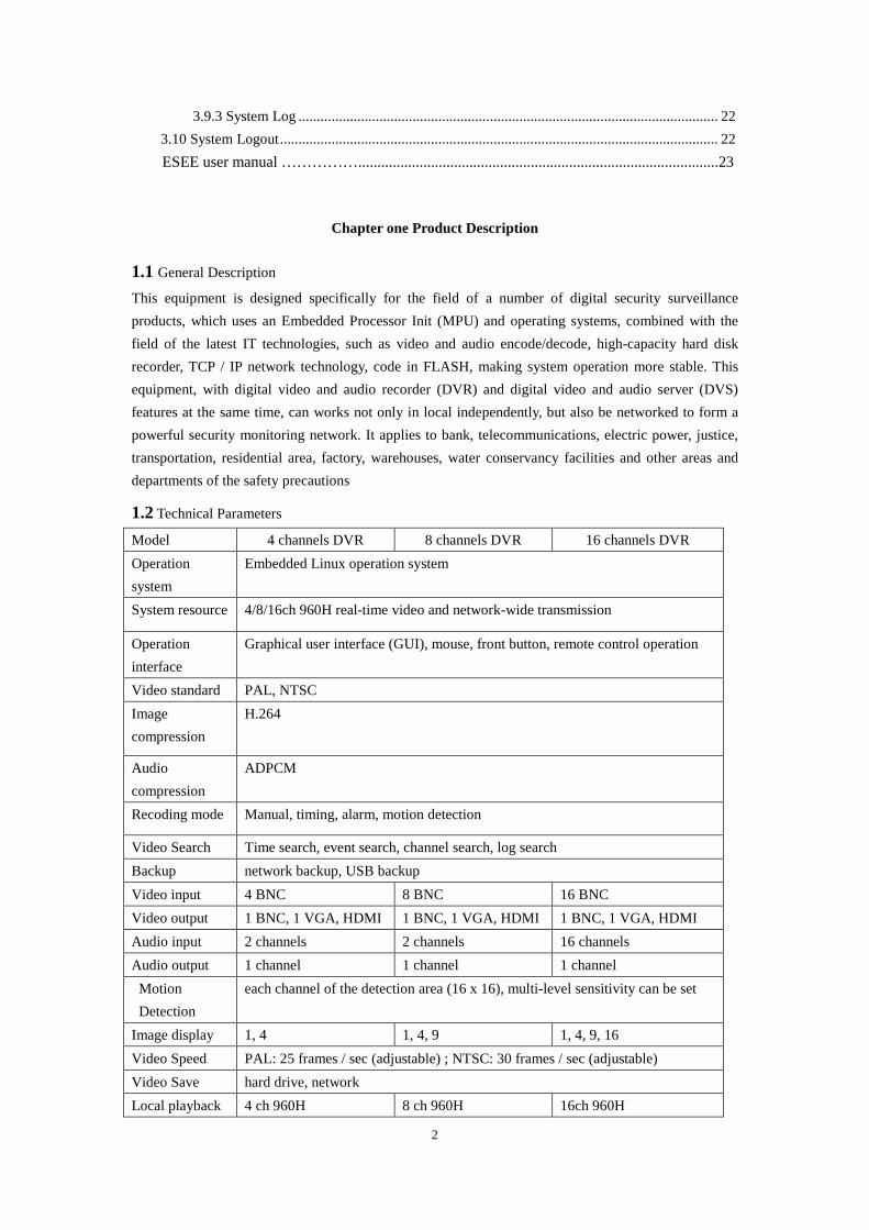
1.2 Technical Parameters
Model 4 channels DVR 8 channels DVR 16 channels DVR
Operation
system
Embedded Linux operation system
System resource 4/8/16ch 960H real-time video and network-wide transmission
Operation
interface
Graphical user interface (GUI), mouse, front button, remote control operation
Video standard PAL, NTSC
Image
compression
H.264
Audio
compression
ADPCM
Recoding mode Manual, timing, alarm, motion detection
Video Search Time search, event search, channel search, log search
Backup network backup, USB backup
Video input 4 BNC 8 BNC 16 BNC
Video output 1 BNC, 1 VGA, HDMI 1 BNC, 1 VGA, HDMI 1 BNC, 1 VGA, HDMI
Audio input 2 channels 2 channels 16 channels
Audio output 1 channel 1 channel 1 channel
Motion
Detection
each channel of the detection area (16 x 16), multi-level sensitivity can be set
Image display 1, 4 1, 4, 9 1, 4, 9, 16
Video Speed PAL: 25 frames / sec (adjustable) ; NTSC: 30 frames / sec (adjustable)
Video Save hard drive, network
Local playback 4 ch 960H 8 ch 960H 16ch 960H
3
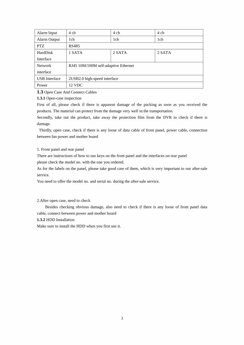
Alarm Input 4 ch 4 ch 4 ch
Alarm Output 1ch 1ch 1ch
PTZ RS485
HardDisk
Interface
1 SATA 2 SATA 2 SATA
Network
interface
RJ45 10M/100M self-adaptive Ethernet
USB Interface 2USB2.0 high-speed interface
Power 12 VDC
1.3 Open Case And Connect Cables
1.3.1 Open-case inspection
First of all, please check if there is apparent damage of the packing as soon as you received the
products. The material can protect from the damage very well in the transportation.
Secondly, take out the product, take away the protection film from the DVR to check if there is
damage.
Thirdly, open case, check if there is any loose of data cable of front panel, power cable, connection
between fan power and mother board
1. Front panel and rear panel
There are instructions of how to use keys on the front panel and the interfaces on rear panel
please check the model no. with the one you ordered.
As for the labels on the panel, please take good care of them, which is very important to our after-sale
service.
You need to offer the model no. and serial no. during the after-sale service.
2.After open case, need to check
Besides checking obvious damage, also need to check if there is any loose of front panel data
cable, connect between power and mother board
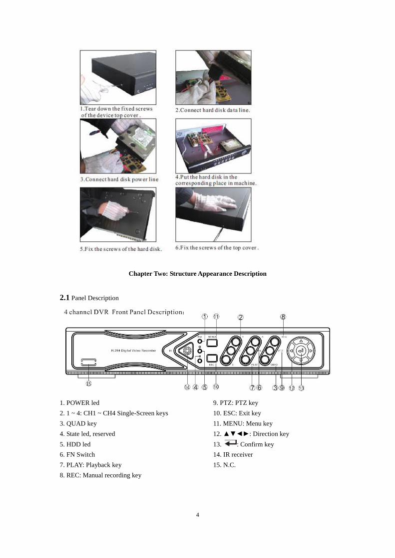
1.3.2 HDD Installation
Make sure to install the HDD when you first use it.
4
Chapter Two: Structure Appearance Description
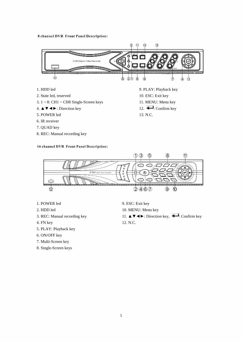
2.1 Panel Description
1. POWER led 9. PTZ: PTZ key
2. 1 ~ 4: CH1 ~ CH4 Single-Screen keys 10. ESC: Exit key
3. QUAD key 11. MENU: Menu key
4. State led, reserved 12. ▲▼◄►: Direction key
5. HDD led 13. : Confirm key
6. FN Switch 14. IR receiver
7. PLAY: Playback key 15. N.C.
8. REC: Manual recording key
5
1. HDD led 9. PLAY: Playback key
2. State led, reserved 10. ESC: Exit key
3. 1 ~ 8: CH1 ~ CH8 Single-Screen keys 11. MENU: Menu key
4. ▲▼◄►: Direction key 12. : Confirm key
5. POWER led 13. N.C.
6. IR receiver
7. QUAD key
8. REC: Manual recording key
1. POWER led 9. ESC: Exit key
2. HDD led 10. MENU: Menu key
3. REC: Manual recording key 11. ▲▼◄►: Direction key, : Confirm key
4. FN key 12. N.C.
5. PLAY: Playback key
6. ON/OFF key
7. Multi-Screen key
8. Single-Screen keys
6
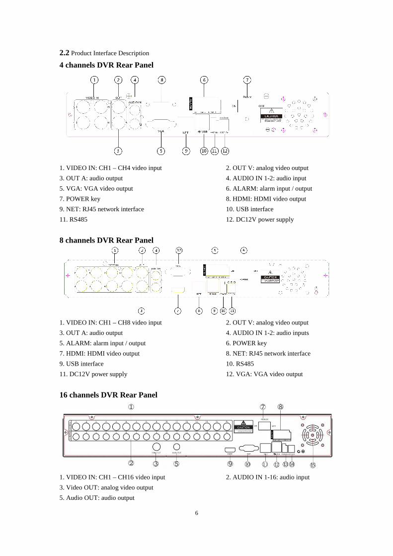
2.2 Product Interface Description
4 channels DVR Rear Panel
1. VIDEO IN: CH1 – CH4 video input 2. OUT V: analog video output
3. OUT A: audio output 4. AUDIO IN 1-2: audio input
5. VGA: VGA video output 6. ALARM: alarm input / output
7. POWER key 8. HDMI: HDMI video output
9. NET: RJ45 network interface 10. USB interface
11. RS485 12. DC12V power supply
8 channels DVR Rear Panel
1. VIDEO IN: CH1 – CH8 video input 2. OUT V: analog video output
3. OUT A: audio output 4. AUDIO IN 1-2: audio inputs
5. ALARM: alarm input / output 6. POWER key
7. HDMI: HDMI video output 8. NET: RJ45 network interface
9. USB interface 10. RS485
11. DC12V power supply 12. VGA: VGA video output
16 channels DVR Rear Panel
1. VIDEO IN: CH1 – CH16 video input 2. AUDIO IN 1-16: audio input
3. Video OUT: analog video output
5. Audio OUT: audio output
7
7. POWER key 8. ALARM: alarm input / output
9. HDMI: HDMI video output 10. VGA: VGA video output
11. NET: RJ45 network interface 12. USB interface
13. RS485 14. DC12V power supply
15. Fan
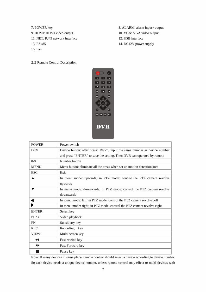
2.3 Remote Control Description
POWER Power switch
DEV Device button: after press" DEV", input the same number as device number
and press “ENTER” to save the setting. Then DVR can operated by remote
0-9 Number button
MENU Menu button; eliminate all the areas when set up motion detection area
ESC Exit
▲ In menu mode: upwards; in PTZ mode: control the PTZ camera revolve
upwards
▼ In menu mode: downwards; in PTZ mode: control the PTZ camera revolve
downwards
In menu mode: left; in PTZ mode: control the PTZ camera revolve left
In menu mode: right; in PTZ mode: control the PTZ camera revolve right
ENTER Select key
PLAY Video playback
FN Subsidiary key
REC Recording key
VIEW Multi-screen key
Fast rewind key
Fast Forward key
Pause key
Note: If many devices in same place, remote control should select a device according to device number.
So each device needs a unique device number, unless remote control may effect to multi-devices with
8
the same number.
Chapter Three: Description of Operation System
3.1 Turn ON / OFF
Confirm that AC voltage accessible matches with DVR. Ensure that the DVR power outlet connect
with a good middle ground grounding. After switching power, the device started, 【POWER】 light is
on. Turn into system, if the panel status light flashing, it's normal conditions.
3.2 Preview
After device start, preview interface can be seen immediately. In the preview interface you can see the
system date, time, channel name. Press corresponding number key of panel or click the left mouse
button, user can preview the single channel. Press "QUAD" key in the panel or click the left mouse
button, to return to a multi-interface monitoring state.
3.3 Menu operation instructions
3.3.1 Menu
【MENU】,enter the device's main menu interface. 【PLAY】 shortcut keys for playback interface.
【REC】shortcut keys for manual recording.【PTZ】shortcut keys for PTZ control.
Note: Default password is empty, click "enter" can into menu directly.
3.3.2 Menu composition
Menu component units as following:
(1) Check box: two kinds of status available, "√" means valid, "□" means invalid , direction key:
【↑】【↓】【←】【--->】,enter key【 】. Also, click the left mouse button to choose.
For example: "channel" and "video mode" check box in the video research.
(2) Selection box: select the target content according to the drop-down box options. Use
【↑】, 【↓】 key or click the left mouse button to select.
For example: "channel" and "code stream" in the encode setup menu
(3) List Box: Displays the research information in the list, you can try one option for operation
For example: Press【 】 button in the video backup file. or the left mouse button.
(4)Edit box: Enter the name into edit box
For example: in the setup menu, you could input numbers, English letters, punctuation and so
on in the "channel" edit box.
a) use panel key 【↑】【↓】【←】, 【→】or move the mouse to edit box , press "" key
or click the left mouse button, then enter keyboard appears, select the desired input target
characters through the arrow keys or click the left mouse button.
9
b) After input the information, click 【OK】【CANCEL】 button or button【ESC】can safe
or exit
(5) Button: used to implement a specific function or enter the next setup menu, click【OK
/ 】 key and the left mouse button.
3.3.3 ESC MENU
Press 【MENU】, 【ESC】 or the right mouse button to exit the menu mode
Click the right mouse button and return to the previous menu level.
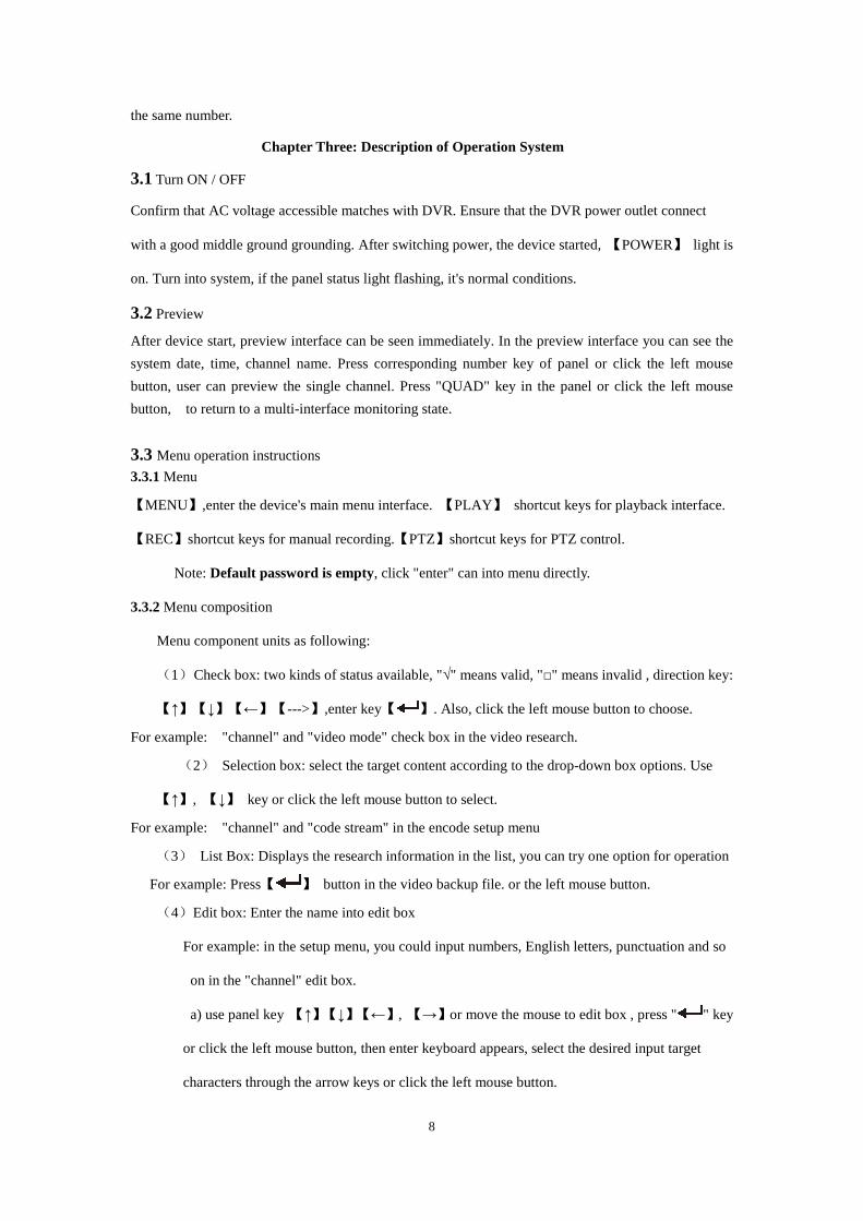
3.4 Main Menu Introduction
Press MENU key or right mouse, it will pop-up the main menu. Main menu consists of the
following three components
Preview mode: select corresponding preview mode in the menu column.
Shortcut menu: in menu column, there are: digital zoon, video playback, manual record, PTZ control,
volume , setup ,shut down. User could enter the corresponding menu preview mode.
Setup menu: including video playback, video backup , system setup ,system tools ,system info,
system logout.
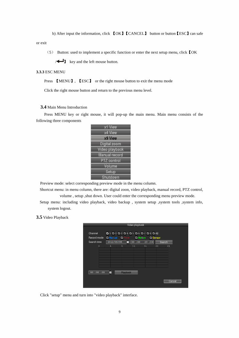
3.5 Video Playback
Click "setup" menu and turn into "video playback" interface.
10
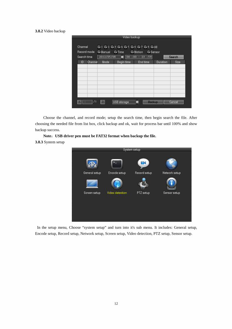
3.5.1 Video Search
Channel:to choose the target channel by clicking the check box. means selected, means
non-selected
Record mode:to choose the recode mode by clicking the check box. means selected, means
non-selected
Search time:input the Starting and finishing time into edit box
Search:After setup the above search condition, click "search" to begin the corresponding video file
searching and show the files. Red means time recording, green means MD recording,
yellow means sensor recording.
Playback:chose playback and turn into playback interface. In the search list box, choose the time
bucket according up , down, left ,right key or move the mouse. Click 【 】or left
mouse to enter "video playback "Interface
Cancel:back to previous menu .
3.5.2 Playback toolbar
Select the playback file or time playback file, it will turn into video playback interface.
Playback toolbar : it will show below the playback interface. Each channel can magnify or narrow by
clicking the left mouse .
Stop play:click to stop the video and turn back to playback interface.
Pause/play:click can pause the playback video, click can continue the playback video.
Fast forward :click can fast forward the video, also times fast forward the video by click the
button again.
Exit playback:click “ESC”or can exit the playback video; or exit until all file have been played.
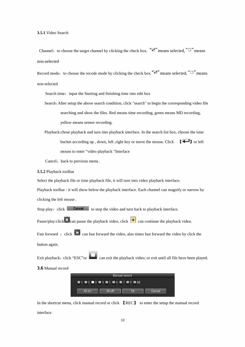
3.6 Manual record
In the shortcut menu, click manual record or click 【REC】 to enter the setup the manual record
interface.
11
Manual record menu include several parts:
Channel:☑”means open; “□”means close.
All on: start all the channel.
All off: close all the channel.
OK: confirm and exit
Cancel: click cancel can exit the manual record interface and back to main menu.
Remarks: the video which start by manual must be turned off by manual, otherwise the recording will
be always continue.
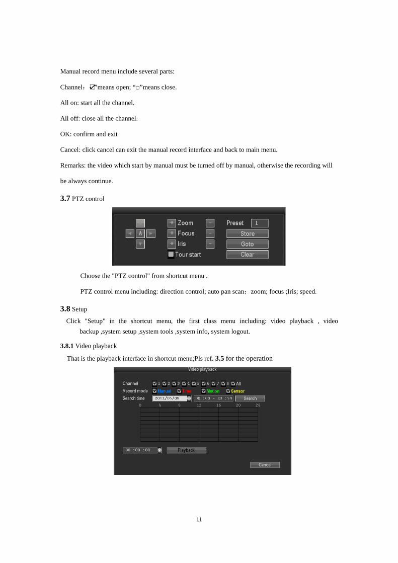
3.7 PTZ control
Choose the "PTZ control" from shortcut menu .
PTZ control menu including: direction control; auto pan scan;zoom; focus ;Iris; speed.
3.8 Setup
Click "Setup" in the shortcut menu, the first class menu including: video playback , video
backup ,system setup ,system tools ,system info, system logout.
3.8.1 Video playback
That is the playback interface in shortcut menu;Pls ref. 3.5 for the operation
12
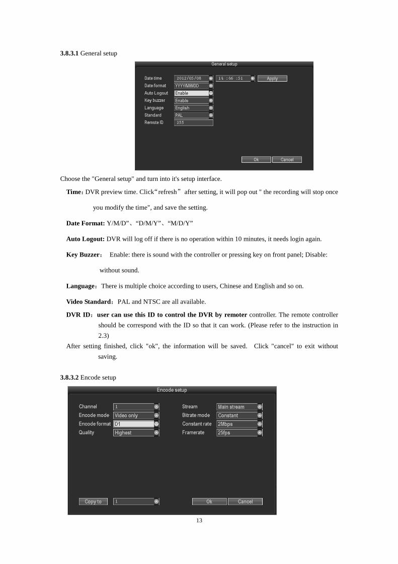
3.8.2 Video backup
Choose the channel, and record mode; setup the search time, then begin search the file. After
choosing the needed file from list box, click backup and ok, wait for process bar until 100% and show
backup success.
Note:USB driver pen must be FAT32 format when backup the file.
3.8.3 System setup
In the setup menu, Choose “system setup” and turn into it's sub menu. It includes: General setup,
Encode setup, Record setup, Network setup, Screen setup, Video detection, PTZ setup, Sensor setup.
13
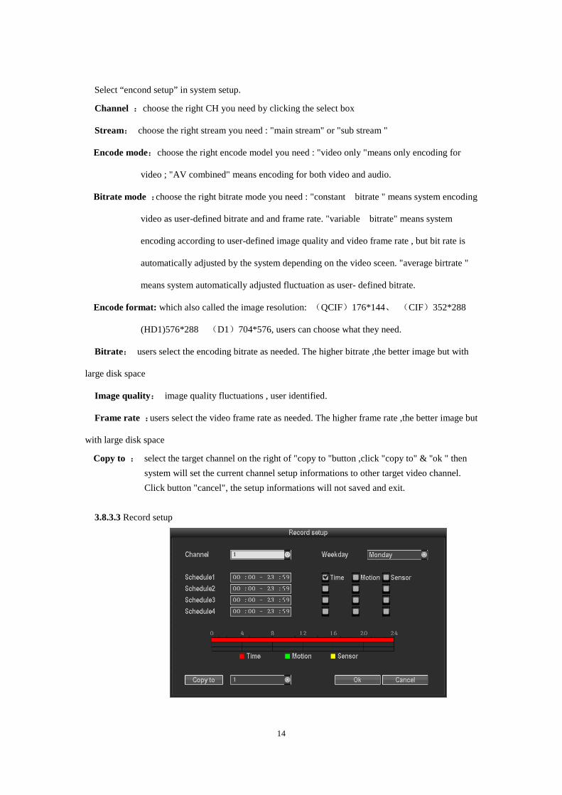
3.8.3.1 General setup
Choose the "General setup" and turn into it's setup interface.
Time:DVR preview time. Click“refresh” after setting, it will pop out " the recording will stop once
you modify the time", and save the setting.
Date Format: Y/M/D”、“D/M/Y” 、“M/D/Y”
Auto Logout: DVR will log off if there is no operation within 10 minutes, it needs login again.
Key Buzzer: Enable: there is sound with the controller or pressing key on front panel; Disable:
without sound.
Language:There is multiple choice according to users, Chinese and English and so on.
Video Standard:PAL and NTSC are all available.
DVR ID:user can use this ID to control the DVR by remoter controller. The remote controller
should be correspond with the ID so that it can work. (Please refer to the instruction in
2.3)
After setting finished, click "ok", the information will be saved. Click "cancel" to exit without
saving.
3.8.3.2 Encode setup
14
Select “encond setup” in system setup.
Channel :choose the right CH you need by clicking the select box
Stream: choose the right stream you need : "main stream" or "sub stream "
Encode mode:choose the right encode model you need : "video only "means only encoding for
video ; "AV combined" means encoding for both video and audio.
Bitrate mode :choose the right bitrate mode you need : "constant bitrate " means system encoding
video as user-defined bitrate and and frame rate. "variable bitrate" means system
encoding according to user-defined image quality and video frame rate , but bit rate is
automatically adjusted by the system depending on the video sceen. "average birtrate "
means system automatically adjusted fluctuation as user- defined bitrate.
Encode format: which also called the image resolution: (QCIF)176*144、 (CIF)352*288
(HD1)576*288 (D1)704*576, users can choose what they need.
Bitrate: users select the encoding bitrate as needed. The higher bitrate ,the better image but with
large disk space
Image quality: image quality fluctuations , user identified.
Frame rate :users select the video frame rate as needed. The higher frame rate ,the better image but
with large disk space
Copy to : select the target channel on the right of "copy to "button ,click "copy to" & ''ok " then
system will set the current channel setup informations to other target video channel.
Click button "cancel", the setup informations will not saved and exit.
3.8.3.3 Record setup
15
Select “record setup” in system setup.
Channel :chose the target channel by clicking the select box
Weekday : chose the correspond day as user's need, "ALL" means record all date.
Recording mode and time:in the time edit box, user can set different time with different recoding
mode . "Time " : in red color , "Motion": in green color , "Sensor": in yellow color ; “☑" means
selected, “□” means invalid. There is times status display which 0~24 hours for whole schedule.
Copy to: select the target channel on the right of "copy to "button ,click "copy to" & ''ok " then
system will set the current channel setup informations to other target video channel. Click button
"cancel", the setup informations is non-saved but to exit.
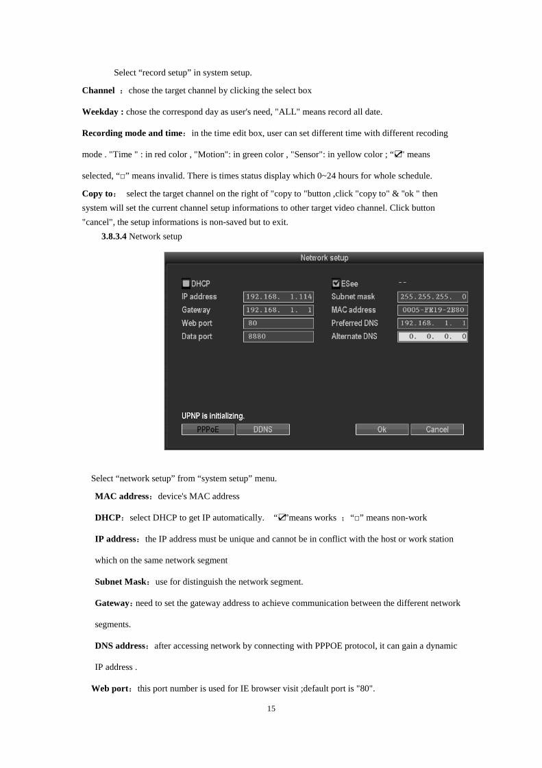
3.8.3.4 Network setup
Select “network setup” from “system setup” menu.
MAC address:device's MAC address
DHCP:select DHCP to get IP automatically. “☑”means works ;“□” means non-work
IP address:the IP address must be unique and cannot be in conflict with the host or work station
which on the same network segment
Subnet Mask:use for distinguish the network segment.
Gateway:need to set the gateway address to achieve communication between the different network
segments.
DNS address:after accessing network by connecting with PPPOE protocol, it can gain a dynamic
IP address .
Web port:this port number is used for IE browser visit ;default port is "80".
16
Data port: this port number is used for device and mobile visit ; suggest to set the port above 2000.
NOTE: To view images of DVRs art. SDVR040A, SDVR080A and SDVR160A from smartphones
(iOS or Android OS) please use the app "ESEENET+" which is freely downloadable from the
relative stores (Apple Store and Play Store). The same app for smartphones has to be used for
tablet devices.
ESee: after connecting internet , click“☑ Esee” and save the setting, user will get an Esee ID. You
can remote DVR with this ID by www.dvrskype.com. It's free DDNS, no need to apply the
domain name from any server.
PPPOE configuration
Start using:“☑ PPPOE” means to start up dial-up by PPPOE protocol, “□” means stop it.
PPPOE user: input the user name of ISP into edit box
PPPOE password:input the password of ISP into edit box
After the page setup is completed, click '"OK " to save the changes and exit ; click "cancel ", to exit
the setting.
DDNS: The automatic analytic function of dynamic domain name, it could supported Comelit DNS,
etc. To use Comelit DNS see the last page of this manual.
In the "network setup" menu, click " DDNS " to enter it's setup interface
Start using:“☑”means DDNS service start using ;“□”means stop using.
Select the corresponding network server and input user name, password and domain name (please
refer to 3.3.2(4))
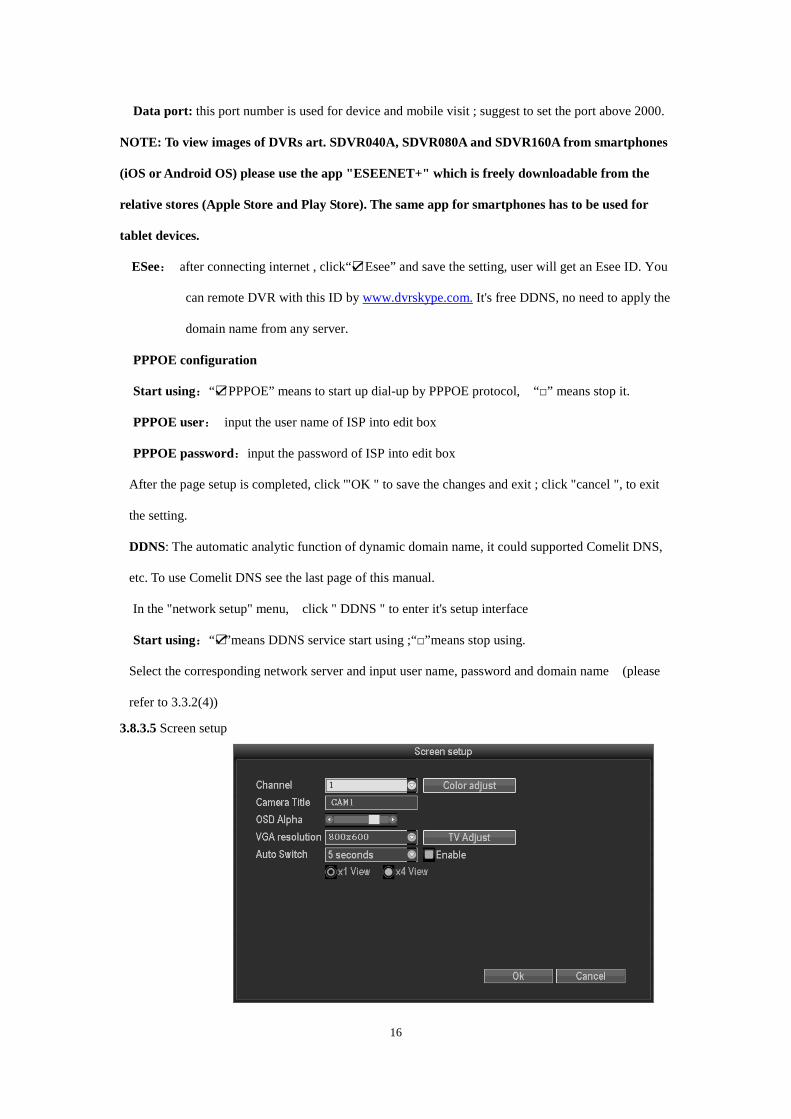
3.8.3.5 Screen setup
17
Select “screen setup” from “system setup” menu
Channel:chose the target channel by clicking select box.
Camera title:user can edit the channel title from the edit box. “☑” means display channel title,
“□”means non-display.
OSD Alpha: user can adjusted the OSD menu transparency as needed.
OSD time:“☑”display system time,“□” non- display;
Auto Switch:user can setup the time of auto switching for preview image, it switch in single screen
or 4 Channels screen.
Start using:“☑”start using ,“□” stop using
After the setup is completed, click '"OK " to save the changes and exit; click "cancel " to exit the
setting.
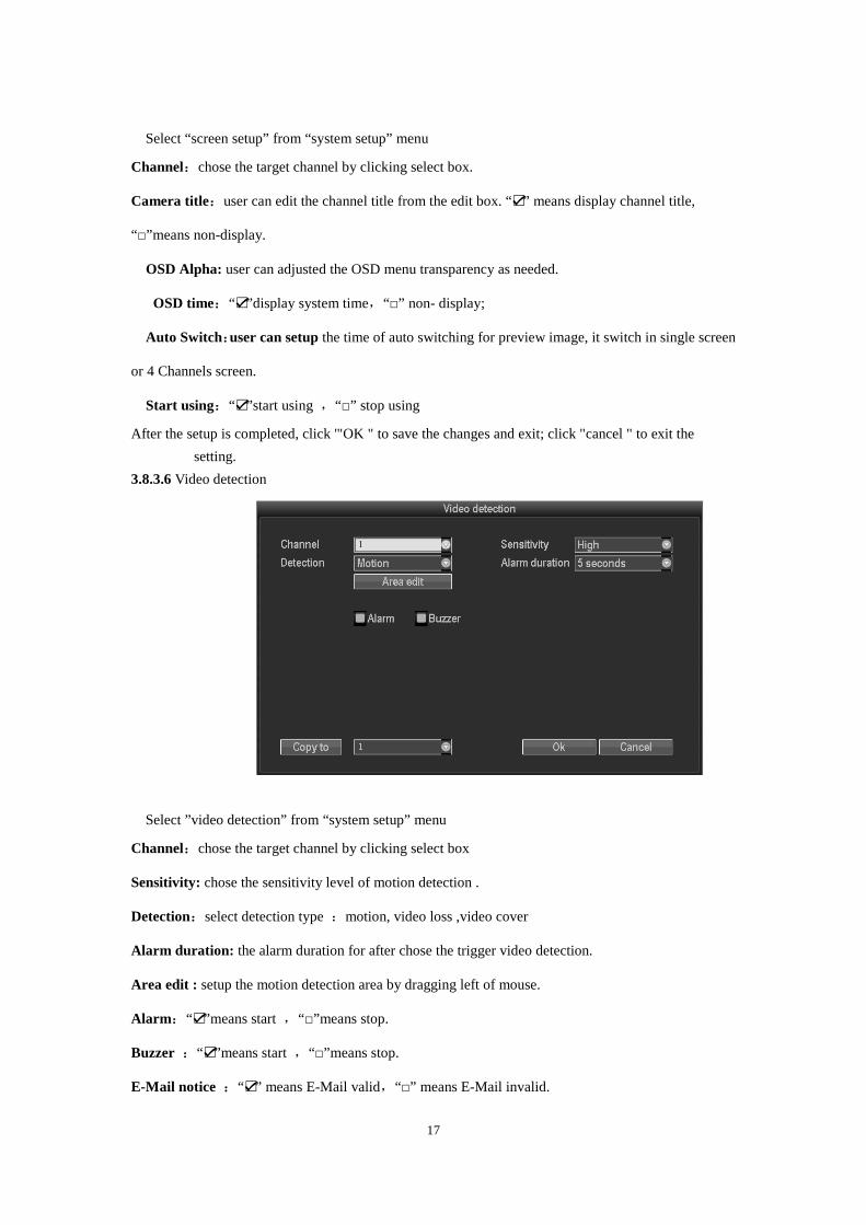
3.8.3.6 Video detection
Select ”video detection” from “system setup” menu
Channel:chose the target channel by clicking select box
Sensitivity: chose the sensitivity level of motion detection .
Detection:select detection type :motion, video loss ,video cover
Alarm duration: the alarm duration for after chose the trigger video detection.
Area edit : setup the motion detection area by dragging left of mouse.
Alarm:“☑”means start ,“□”means stop.
Buzzer :“☑”means start ,“□”means stop.
E-Mail notice :“☑” means E-Mail valid,“□” means E-Mail invalid.
18
Copy to : select the channel and click "copy to" &
''ok " to copy the same setting to other channel. Or user can choose copy to "all" to
make all channel in same stetting . Click button "cancel", the setup information will be
non-saved but exit.
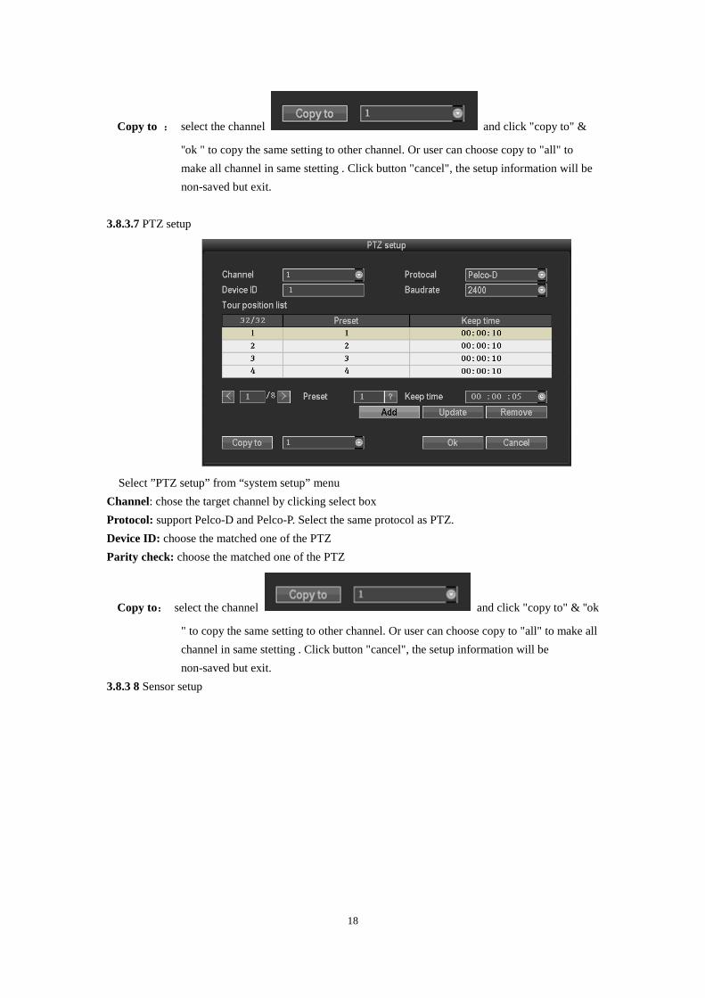
3.8.3.7 PTZ setup
Select ”PTZ setup” from “system setup” menu
Channel: chose the target channel by clicking select box
Protocol: support Pelco-D and Pelco-P. Select the same protocol as PTZ.
Device ID: choose the matched one of the PTZ
Parity check: choose the matched one of the PTZ
Copy to: select the channel and click "copy to" & ''ok
" to copy the same setting to other channel. Or user can choose copy to "all" to make all
channel in same stetting . Click button "cancel", the setup information will be
non-saved but exit.
3.8.3 8 Sensor setup
19
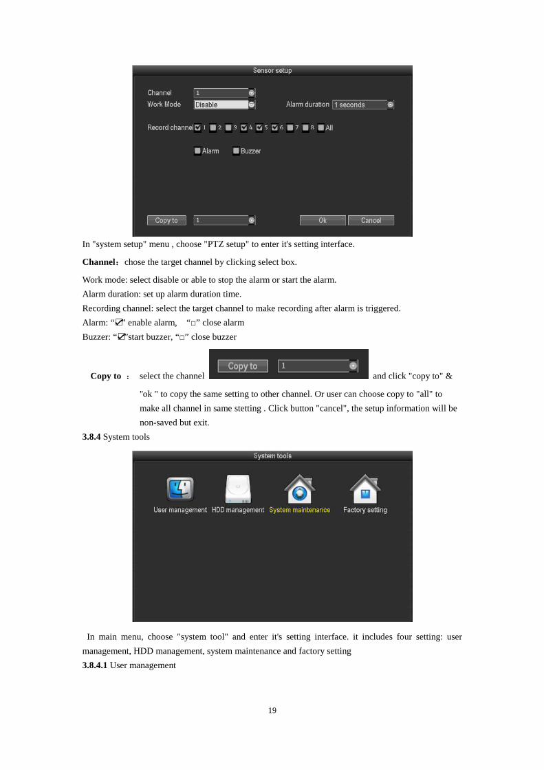
In "system setup" menu , choose "PTZ setup" to enter it's setting interface.
Channel:chose the target channel by clicking select box.
Work mode: select disable or able to stop the alarm or start the alarm.
Alarm duration: set up alarm duration time.
Recording channel: select the target channel to make recording after alarm is triggered.
Alarm: “☑” enable alarm, “□” close alarm
Buzzer: “☑”start buzzer, “□” close buzzer
Copy to : select the channel and click "copy to" &
''ok " to copy the same setting to other channel. Or user can choose copy to "all" to
make all channel in same stetting . Click button "cancel", the setup information will be
non-saved but exit.
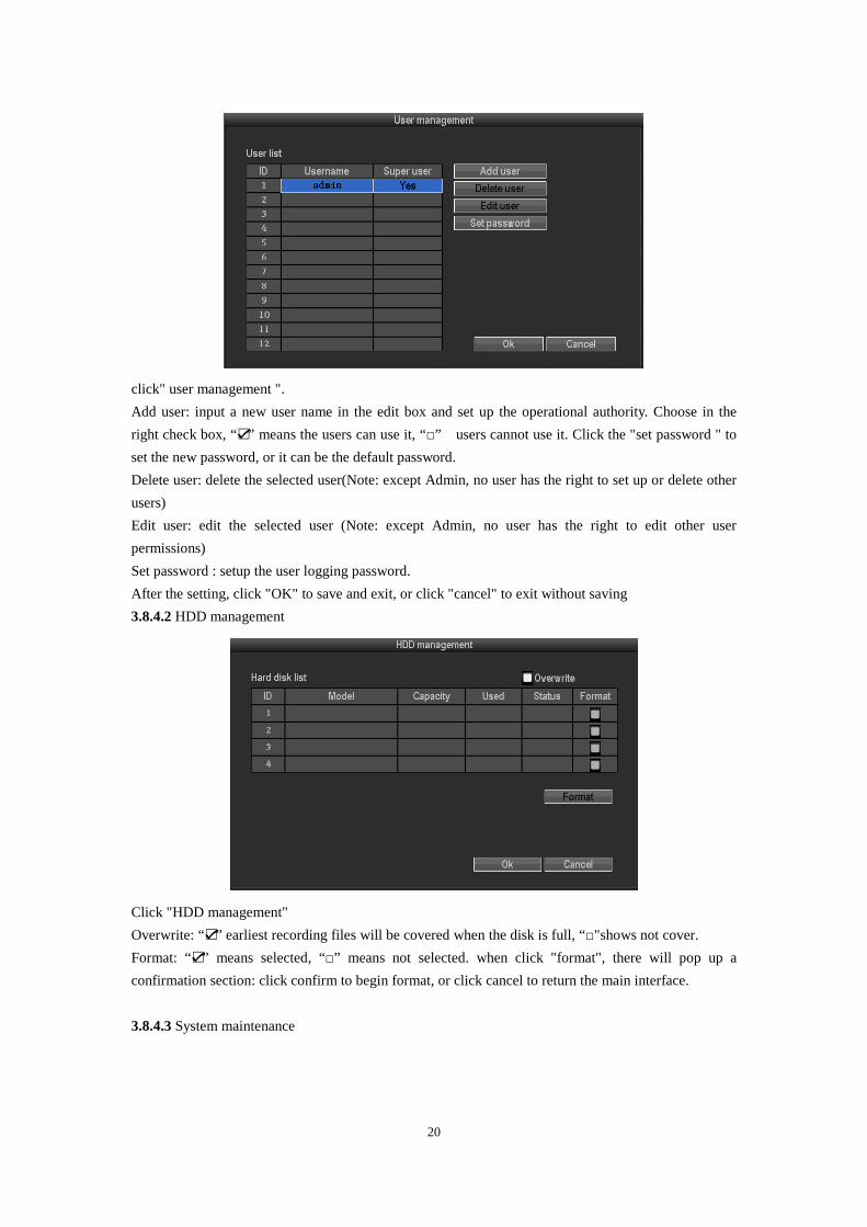
3.8.4 System tools
In main menu, choose "system tool" and enter it's setting interface. it includes four setting: user
management, HDD management, system maintenance and factory setting
3.8.4.1 User management
20
click" user management ".
Add user: input a new user name in the edit box and set up the operational authority. Choose in the
right check box, “☑” means the users can use it, “□” users cannot use it. Click the "set password " to
set the new password, or it can be the default password.
Delete user: delete the selected user(Note: except Admin, no user has the right to set up or delete other
users)
Edit user: edit the selected user (Note: except Admin, no user has the right to edit other user
permissions)
Set password : setup the user logging password.
After the setting, click "OK" to save and exit, or click "cancel" to exit without saving
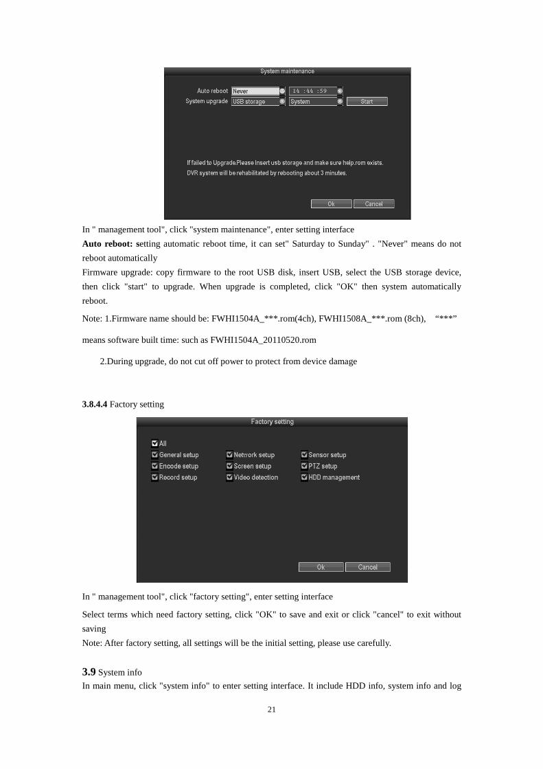
3.8.4.2 HDD management
Click "HDD management"
Overwrite: “☑” earliest recording files will be covered when the disk is full, “□"shows not cover.
Format: “☑” means selected, “□” means not selected. when click "format", there will pop up a
confirmation section: click confirm to begin format, or click cancel to return the main interface.
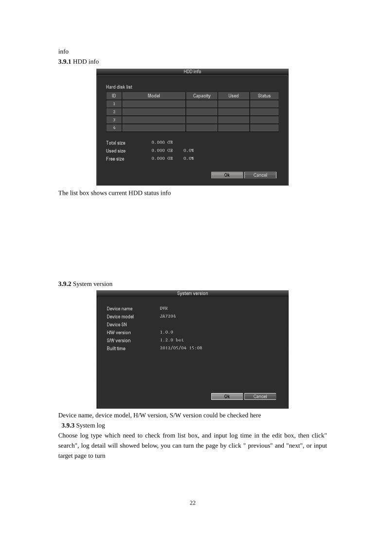
3.8.4.3 System maintenance
21
In " management tool", click "system maintenance", enter setting interface
Auto reboot: setting automatic reboot time, it can set" Saturday to Sunday" . "Never" means do not
reboot automatically
Firmware upgrade: copy firmware to the root USB disk, insert USB, select the USB storage device,
then click "start" to upgrade. When upgrade is completed, click "OK" then system automatically
reboot.
Note: 1.Firmware name should be: FWHI1504A_***.rom(4ch), FWHI1508A_***.rom (8ch), “***”
means software built time: such as FWHI1504A_20110520.rom
2.During upgrade, do not cut off power to protect from device damage
3.8.4.4 Factory setting
In " management tool", click "factory setting", enter setting interface
Select terms which need factory setting, click "OK" to save and exit or click "cancel" to exit without
saving
Note: After factory setting, all settings will be the initial setting, please use carefully.
3.9 System info
In main menu, click "system info" to enter setting interface. It include HDD info, system info and log
22
info
3.9.1 HDD info
The list box shows current HDD status info
3.9.2 System version
Device name, device model, H/W version, S/W version could be checked here
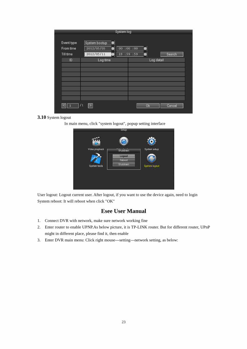
3.9.3 System log
Choose log type which need to check from list box, and input log time in the edit box, then click"
search", log detail will showed below, you can turn the page by click " previous" and "next", or input
target page to turn
23
3.10 System logout
In main menu, click "system logout", popup setting interface
User logout: Logout current user. After logout, if you want to use the device again, need to login
System reboot: It will reboot when click "OK"
Esee User Manual
1. Connect DVR with network, make sure network working fine
2. Enter router to enable UPNP.As below picture, it is TP-LINK router. But for different router, UPnP
might in different place, please find it, then enable
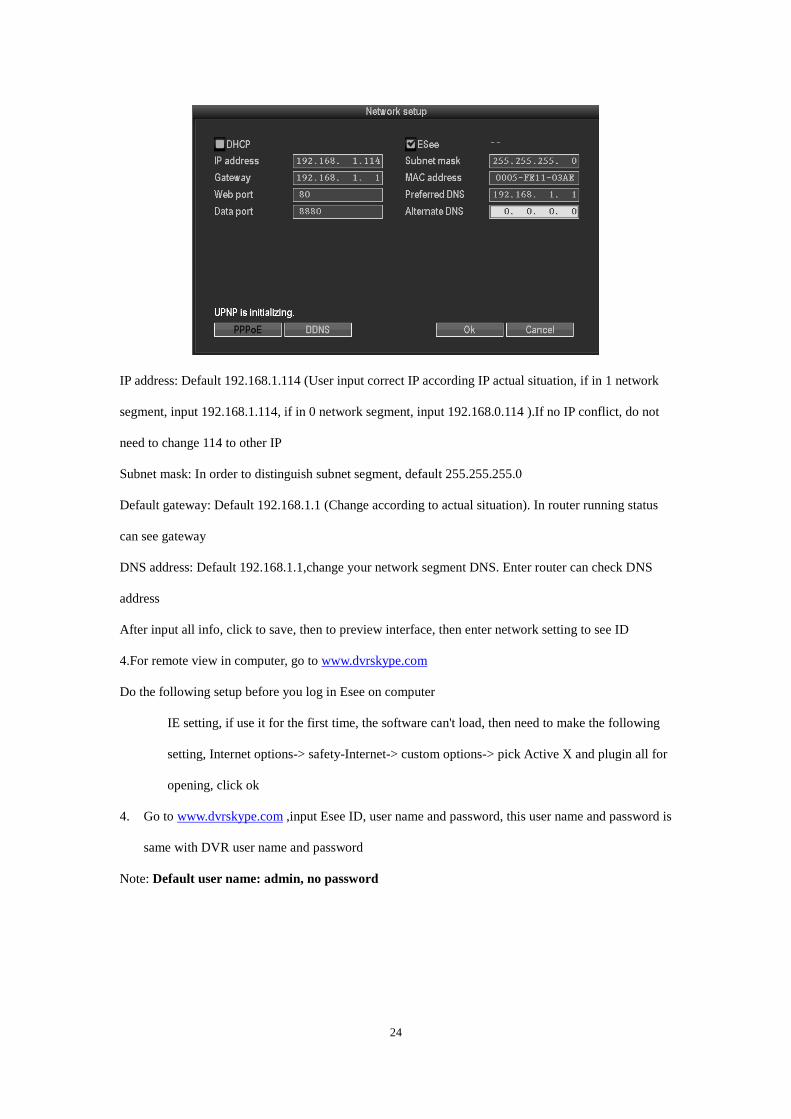
3. Enter DVR main menu: Click right mouse---setting---network setting, as below:
24
IP address: Default 192.168.1.114 (User input correct IP according IP actual situation, if in 1 network
segment, input 192.168.1.114, if in 0 network segment, input 192.168.0.114 ).If no IP conflict, do not
need to change 114 to other IP
Subnet mask: In order to distinguish subnet segment, default 255.255.255.0
Default gateway: Default 192.168.1.1 (Change according to actual situation). In router running status
can see gateway
DNS address: Default 192.168.1.1,change your network segment DNS. Enter router can check DNS
address
After input all info, click to save, then to preview interface, then enter network setting to see ID
4.For remote view in computer, go to www.dvrskype.com
Do the following setup before you log in Esee on computer
IE setting, if use it for the first time, the software can't load, then need to make the following
setting, Internet options-> safety-Internet-> custom options-> pick Active X and plugin all for
opening, click ok
4. Go to www.dvrskype.com ,input Esee ID, user name and password, this user name and password is
same with DVR user name and password
Note: Default user name: admin, no password
25
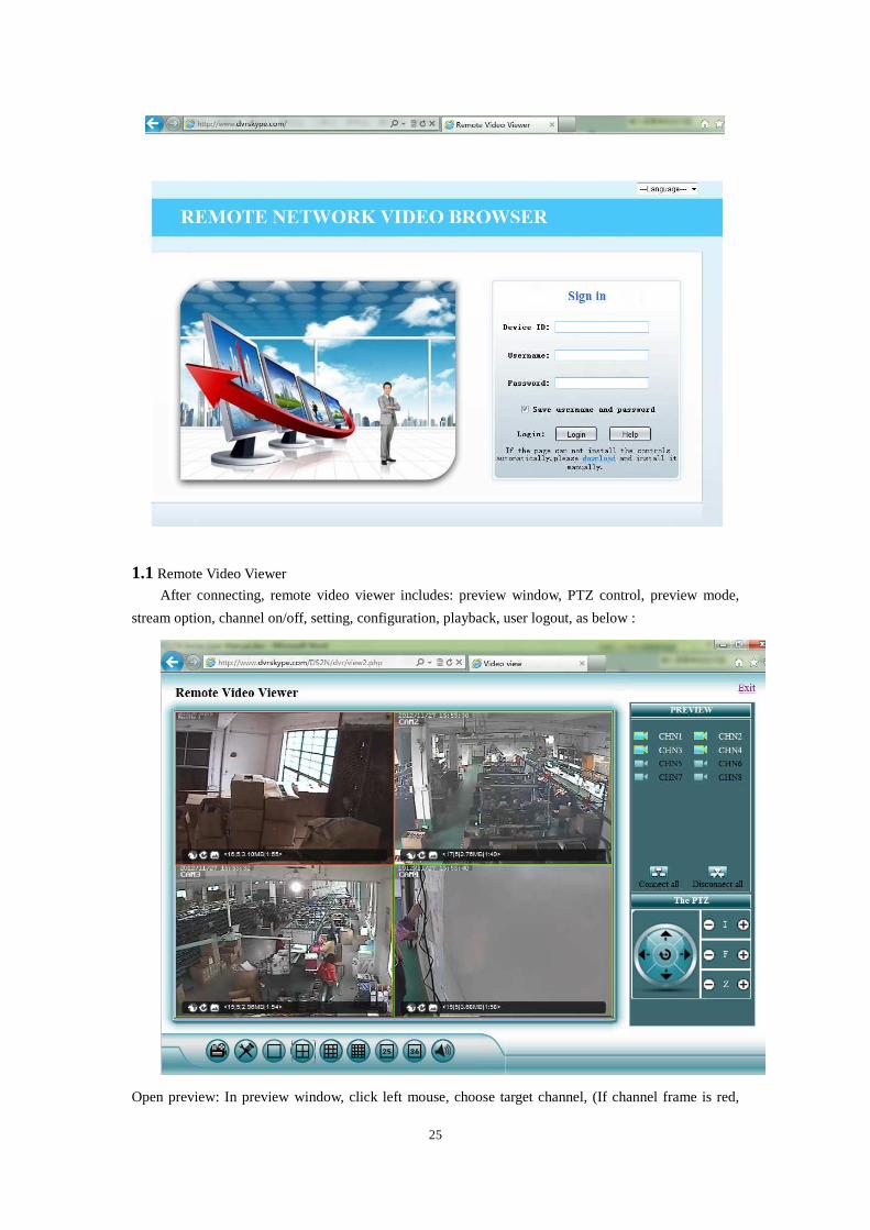
1.1 Remote Video Viewer
After connecting, remote video viewer includes: preview window, PTZ control, preview mode,
stream option, channel on/off, setting, configuration, playback, user logout, as below :
Open preview: In preview window, click left mouse, choose target channel, (If channel frame is red,
26
means select). In channel on/off table, click left mouse, can open or close that channel video, such as:
on; off
Preview mode: In preview mode switch table, can click to choose mode, or double click
channel to signal channel preview mode, or switch to multi-channel mode.
COMELIT DNS SERVICE For this series of DVR is now available the Comelit DNS service.
To use it proceed as follows:
1 – check the firmware version of the device. The service is available from the version 1.8.3 dated
20140527. If necessary, update the firmware
2 – verify that on the device, nearby the label showing the model, is present the label with the univocal
code for the DNS service registration. In case it was not present, contact Comelit Technical support
3 – connect to the site http://www.comelitdns.com , sign up by following the instructions and then
create a host using the activation code above
4 – enter the data (hostname, user and password) in the appropriate DVR menu
5 – to connect to the device registered, enter http://hostname.comelitdns.com:port (if different from 80)
Via Don Arrigoni, 5 24020 Rovetta S. Lorenzo (Bergamo)
http://www.comelitgroup.com e-mail:[email protected]

27