3xtend EINC L/230 installation Instructions · 3xtend/EINC L/230 Installation Instructions TG200812...
16
1 3xtend/EINC L/230 Installation Instructions TG200812 Issue 1/D 5/6/07 Important: Retain these instructions Installation Instructions 3xtend/EINC L/230 Node Controller 1.2 STORING H 2 O +50 °C (122 °F) 0 -10 °C (14 °F) 90 %RH CONTENTS 1 Installation .................................................................... 1 1.1 Unpacking ..................................................................... 1 1.2 Storing ........................................................................... 1 1.3 Installation - Fixing ........................................................ 1 1.4 Installation - Configuration ............................................ 5 2 Replacing a Fuse ........................................................ 13 3 End User Licence Agreement .................................... 15 4 Disposal ...................................................................... 16 1.3 INSTALLATION - FIXING It is recommended that the installation should comply with the HSE Memorandum of Guidance on Electricity at Work Regulations 1989. For USA install equipment in accordance with the National Electric Code. ! WARNING Other than removing front covers, do not attempt to open the unit. Failure to comply may cause damage to the unit. 3xtend/EINC L/230 Installation Instructions TG200812 1 INSTALLATION 1.1 UNPACKING Requirements 2 a H 2 O 0 °C (32 °F) +45 °C (113 °F) 0 %RH 80 %RH b c Dimensions 1 302 mm (11.89”) 60 mm (2.36”) 266 mm (10.47”)
Transcript of 3xtend EINC L/230 installation Instructions · 3xtend/EINC L/230 Installation Instructions TG200812...

13xtend/EINC L/230 Installation Instructions TG200812 Issue 1/D 5/6/07
Important: Retain these instructions
Installation Instructions
3xtend/EINC L/230Node Controller
1.2 STORING
���
+50 °C(122 °F)
0-10 °C(14 °F)
90 %RH
CONTENTS1 Installation .................................................................... 11.1 Unpacking ..................................................................... 11.2 Storing ........................................................................... 1
1.3 Installation - Fixing ........................................................ 11.4 Installation - Configuration ............................................ 52 Replacing a Fuse ........................................................ 133 End User Licence Agreement .................................... 154 Disposal ...................................................................... 16
1.3 INSTALLATION - FIXING
It is recommended that the installationshould comply with the HSE Memorandumof Guidance on Electricity at WorkRegulations 1989.For USA install equipment in accordancewith the National Electric Code.
!WARNINGOther than removing front covers,do not attempt to open the unit.Failure to comply may causedamage to the unit.
3xtend/EINC L/230 InstallationInstructions TG200812
1 INSTALLATION1.1 UNPACKING
Requirements2
a
���
0 °C(32 °F)
+45 °C(113 °F)
0 %RH 80 %RH
b c
Dimensions1
302 mm (11.89”) 60 mm (2.36”)
266
mm
(10
.47”
)
2 3xtend/EINC L/230 Installation Instructions TG200812 Issue 1/D 5/6/07
3xtend/EINC L/230 Installation Instructions
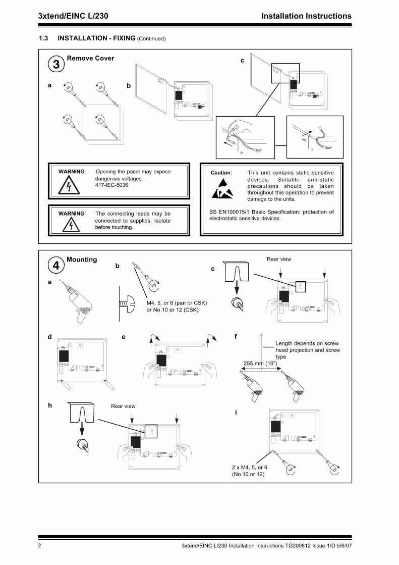
1.3 INSTALLATION - FIXING (Continued)
Remove Cover3
a b
WARNING: Opening the panel may exposedangerous voltages.417-IEC-5036
Caution: This unit contains static sensitivedevices. Suitable anti-staticprecautions should be takenthroughout this operation to preventdamage to the units.
BS EN100015/1 Basic Specification: protection ofelectrostatic sensitive devices.
WARNING: The connecting leads may beconnected to supplies. Isolatebefore touching.
12345678910
12345678910
c
Mounting4
a
b
M4, 5, or 6 (pan or CSK)or No 10 or 12 (CSK)
c
� � � � � � � � �
Rear view
d
� � � � � � � � �
e f
255 mm (10”)
Length depends on screwhead projection and screwtype
h
� � � � � � � � �
Rear viewi
� � � � � � � � �
2 x M4, 5, or 6(No 10 or 12)
� � � � � � � � �

33xtend/EINC L/230 Installation Instructions TG200812 Issue 1/D 5/6/07
Installation Instructions 3xtend/EINC L/230
1.3 INSTALLATION - FIXING (Continued)
Route Cables5 Either or
use M20 grommet use M20 Copex glands
Pushouts
c
DO NOT APPLYPOWER
�
�
Connect Power
Use shrouded plugTerminal size 0.5 to 2.5mm2 (14 to 20 AWG)
6
� � � � � � � � � � � � � � � � � �
� � � �� �
�
� � � �
� � � � � � � � �
� � � � � � �
� � � � � � � � � � �
� � � � � � � �
� � � � � � � � � � � � � � � � � � � � � � �� � � � � � � � � � � � � � � �
� � �
�
� � �
� � �
� � � � � � � � � � �
� � � � �
� � � � � � � � �
� �
� � � � � � � � � � � � � � � � � � � � � � �
� � �
� � � � �� � � � � � � � � � � � � � � �
� ! � � � � � � " # $ % � &
� � � � � � � � � � � � � � � � � � � � � � �
� � � � �� � � � � � � � � � � � � � � �� ' � � � ( � � � � � � � �
� ! � � � �
� � $ � ) # *
WARNING: This apparatus must be earthed (via mains supply cable).
~L N E
L N E
a b
d e
� � � � � � � � � � � � � � � � � �
� � � �� �
�
� � � �
� � � � � � � � �
� � � � � � �
� � � � � � � � � � �
� � � � � � � �
� � � � � � � � � � � � � � � � � � � � � � �� � � � � � � � � � � � � � � �
� � �
�
� � �
� � �
� � � � � � � � � � �
� � � � �
� � � � � � � � �
+ $ , ) � & ) $
Connect Ethernet7
100
m (1
09 y
ds)
Ethernet hub/switch
Connect to an Ethernet hubUse Ethernet cable.
EINC L
RJ45 Connector
RJ45 Connector
Maximum Cable distance100 m (109 yds)
IQ SystemProductsEngineeringGuide TE200369

4 3xtend/EINC L/230 Installation Instructions TG200812 Issue 1/D 5/6/07
3xtend/EINC L/230 Installation Instructions
� � � � � � � � � � � � � � � � � �
� � � �� �
�
� � � �
� � � � � � � � �
� � � � � � �
� � � � � � � � � � �
� � � � � � � �
� � � � � � � � � � � � � � � � � � � � � � �� � � � � � � � � � � � � � � �
� � �
�
� � �
� � �
� � � � � � � � � � �
� � � � �
� � � � � � � � �
� �
� � � � � � � � � � � � � � � � � � � � � � �
� � �
� � � � �� � � � � � � � � � � � � � � �
� ! � � � � � � " # $ % � &
� � � � � � � � � � � � � � � � � � � � � � �
� � � � �� � � � � � � � � � � � � � � �� ' � � � ( � � � � � � � �
� ! � � � �
� � $ � ) # *
1.3 INSTALLATION - FIXING (Continued)
' � - ' � - ' � - ' � -
' � - ' � - ' � - ' � -
2 wire
Connect Current Loop8
X
TT
RR
4 5 6 7T- T+ R- R+
X
TT
RRTT
RR
4 5 6 7T- T+ R- R+
4 wire
Additional terminals
Note only 1 INC type node on a single Lan.
If the 3xtend/EINC L’s current loop is not to be connected (i.e3xtend/EINC L is only to interface between Ethernet andLon) a loop back should be fitted. as shown
1 2 3 4T- T+ R- R+
IMPORTANT
Maximum Cable distance
Terminal size 0.5 to 2.55m2 (14 to 20 AWG)
Terminal size 0.5 to 2.55m2 (14 to 20 AWG)
9 Connect LonWorks Bus
Polarity independentTerminal size 0.5 to 2.55 m2
(14 to 20 AWG)
LON
1 2
Normal current loop Lan cable is not recommended.Do not use screened cable.
Maximum Cable distance
Cable 9k6 baud 19k2 baud 38k4 baud * No. of WiresBelden 9182 1000 m (1090 yds) 700 m (765 yds) 500 m (545 yds) 2Belden 9207 1000 m (1090 yds) 500 m (545 yds) 350 m (380 yds) 2IQ System TP/1/1/22/HF/200 (Belden 8761) 700 m (765 yds) 350 m (380 yds) 250 m (270 yds) 2IQSystem TP/2/2/22/HF/200 (Belden 8723) 500 m (545 yds) 250 m (270 yds) 125 m (135 yds) 4
RecommendedCables Max bus length Max node to
nodeBelden 85102 500 m (545 yds) 500 m (545 yds)TrendTP/1/0/16/HF/200(Belden 8471)
500 m (545 yds) 400 m (430 yds)
UL Level IV, 22 AWG 500 m (545 yds) 400 m (430 yds)JY(St) Y2 x 2 x 0.8 500 m (545 yds) 320 m (350 yds)TIA568A Cat. 5, 24AWG 450 m (490 yds) 250 m (270 yds)
Note that the 3xtend/EINC L is not compatible with LONC.The LONC must be bound on a LonWorks network, and the3xtend/EINC L cannot be bound.

53xtend/EINC L/230 Installation Instructions TG200812 Issue 1/D 5/6/07
Installation Instructions 3xtend/EINC L/230
12345678910
1.3 INSTALLATION - FIXING (Continued)
Replace Cover10
a
b
1.4 INSTALLATION - CONFIGURATION
Fix Unit1
3xtend/EINC L/24Installation Instructionssection 1.3
Switch off2
O
I
1
Note that this product may involveLonWorks system integration. Thisprocedure should only be performed byan installer with LonWorks expertise.
!
12345678910
Remove Cover3
12345678910
WARNING: Opening the panel may exposedangerous voltages.417-IEC-5036 Caution: This unit contains static sensitive devices.
Suitable anti-static precautions should betaken throughout this operation to preventdamage to the units.
ab
c
WARNING: The connecting leads may beconnected to supplies. Isolate beforetouching. BS EN100015/1 Basic Specification: protection of electrostatic
sensitive devices.
6 3xtend/EINC L/230 Installation Instructions TG200812 Issue 1/D 5/6/07
3xtend/EINC L/230 Installation Instructions
� � � � � � � � � � � � � � � � � �
� � � �� �
�
� � � �
� � � � � � � � �
� � � � � � �
� � � � � � � � � � �
� � � � � � � �
� � � � � � � � � � � � � � � � � � � � � � �� � � � � � � � � � � � � � � �
� � �
�
� � �
� � �
� � � � � � � � � � �
� � � � �
� � � � � � � � �
� �
� � � � � � � � � � � � � � � � � � � � � � �
� � �
� � � � �� � � � � � � � � � � � � � � �
� ! � � � � � � " # $ % � &
� � � � � � � � � � � � � � � � � � � � � � �
� � � � �� � � � � � � � � � � � � � � �� ' � � � ( � � � � � � � �
� ! � � � �
� � $ � ) # *
� � � � � � � � � � � � � � � � � �
� � � �� �
�
� � � �
� � � � � � � � �
� � � � � � �
� � � � � � � � � � �
� � � � � � � �
� � � � � � � � � � � � � � � � � � � � � � �� � � � � � � � � � � � � � � �
� � �
�
� � �
� � �
� � � � � � � � � � �
� � � � �
� � � � � � � � �
� �
� � � � � � � � � � � � � � � � � � � � � � �
� � �
� � � � �� � � � � � � � � � � � � � � �
� ! � � � � � � " # $ % � &
� � � � � � � � � � � � � � � � � � � � � � �
� � � � �� � � � � � � � � � � � � � � �� ' � � � ( � � � � � � � �
� ! � � � �
� � $ � ) # *
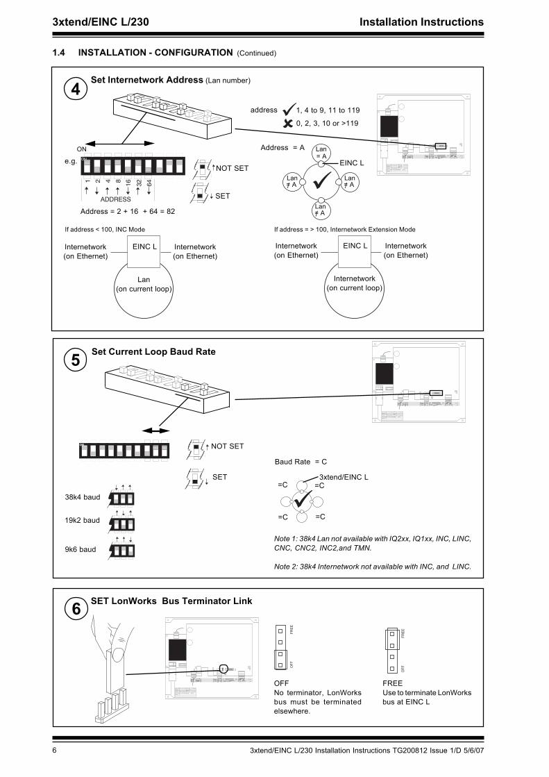
1.4 INSTALLATION - CONFIGURATION (Continued)
ADDRESS
ON
Set Internetwork Address (Lan number)4
SET
NOT SETe.g.
Address = 2 + 16 + 64 = 82
ON= A
EINC L
Lan
Lan/= A
Lan/= A
Lan/= A
If address < 100, INC Mode If address = > 100, Internetwork Extension Mode
Address = A
address 1, 4 to 9, 11 to 119
0, 2, 3, 10 or >119
Internetwork(on Ethernet)
Internetwork(on Ethernet)
EINC L
Lan(on current loop)
Internetwork(on Ethernet)
Internetwork(on Ethernet)
EINC L
Internetwork(on current loop)
Set Current Loop Baud Rate5
SET
NOT SET
3xtend/EINC L
Baud Rate = C
=C
=C
=C
=C
38k4 baud
Note 1: 38k4 Lan not available with IQ2xx, IQ1xx, INC, LINC,CNC, CNC2, INC2,and TMN.
Note 2: 38k4 Internetwork not available with INC, and LINC.
6 SET LonWorks Bus Terminator Link
�..
.-++
OFFNo terminator, LonWorksbus must be terminatedelsewhere.
FREEUse to terminate LonWorksbus at EINC L
�..
.-++
19k2 baud
9k6 baud
73xtend/EINC L/230 Installation Instructions TG200812 Issue 1/D 5/6/07
Installation Instructions 3xtend/EINC L/230
� � � � � � � � � � � � � � � � � �
� � � �� �
�
� � � �
� � � � � � � � �
� � � � � � �
� � � � � � � � � � �
� � � � � � � �
� � � � � � � � � � � � � � � � � � � � � � �� � � � � � � � � � � � � � � �
� � �
�
� � �
� � �
� � � � � � � � � � �
� � � � �
� � � � � � � � �
� �
� � � � � � � � � � � � � � � � � � � � � � �
� � �
� � � � �� � � � � � � � � � � � � � � �
� ! � � � � � � " # $ % � &
� � � � � � � � � � � � � � � � � � � � � � �
� � � � �� � � � � � � � � � � � � � � �� ' � � � ( � � � � � � � �
� ! � � � �
� � $ � ) # *
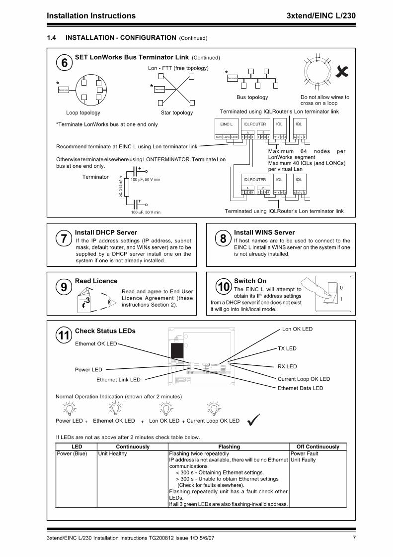
1.4 INSTALLATION - CONFIGURATION (Continued)
� � � � � � � �
� � � � � � � �
� � � � � � � �
Star topology
Bus topology
Loop topology
*Terminate LonWorks bus at one end only
*
LonASCN LonB
EINC L
A
1
IQLROUTER
2 3 4
B
1 2 3 4
IQL
x y
A
1
IQLROUTER
2 3 4
B
1 2 3 4
zw
IQL
x y zw
IQL
x y zw
IQL
x y zw
Recommend terminate at EINC L using Lon terminator link
Otherwise terminate elsewhere using LONTERMINATOR. Terminate Lonbus at one end only.
Lon - FTT (free topology)*
*Do not allow wires tocross on a loop
Maximum 64 nodes perLonWorks segmentMaximum 40 IQLs (and LONCs)per virtual Lan
Terminated using IQLRouter’s Lon terminator link
100 � F, 50 V min
100 � F, 50 V min
Terminator
Terminated using IQLRouter’s Lon terminator link
6 SET LonWorks Bus Terminator Link (Continued)
�
�3
Install DHCP Server7 If the IP address settings (IP address, subnetmask, default router, and WINs server) are to besupplied by a DHCP server install one on thesystem if one is not already installed.
Switch OnRead Licence9 Read and agree to End UserLicence Agreement (theseinstructions Section 2).
10 The EINC L will attempt toobtain its IP address settings
Install WINS Server8 If host names are to be used to connect to theEINC L install a WINS server on the system if oneis not already installed.
Check Status LEDs11
Power LED
Ethernet OK LED
Lon OK LED
Current Loop OK LED
RX LED
TX LED
Ethernet Data LEDEthernet Link LED
Power LED Ethernet OK LED Lon OK LED Current Loop OK LED+ + +
Normal Operation Indication (shown after 2 minutes)
If LEDs are not as above after 2 minutes check table below.
from a DHCP server if one does not existit will go into link/local mode.
LED Continuously Flashing Off ContinuouslyPower (Blue) Unit Healthy Flashing twice repeatedly
IP address is not available, there will be no Ethernetcommunications < 300 s - Obtaining Ethernet settings. > 300 s - Unable to obtain Ethernet settings (Check for faults elsewhere).Flashing repeatedly unit has a fault check otherLEDs.If all 3 green LEDs are also flashing-invalid address.
Power FaultUnit Faulty
8 3xtend/EINC L/230 Installation Instructions TG200812 Issue 1/D 5/6/07
3xtend/EINC L/230 Installation Instructions
� � � � � � � � � � � � � � � � � �
� � � �� �
�
� � � �
� � � � � � � � �
� � � � � � �
� � � � � � � � � � �
� � � � � � � �
� � � � � � � � � � � � � � � � � � � � � � �� � � � � � � � � � � � � � � �
� � �
�
� � �
� � �
� � � � � � � � � � �
� � � � �
� � � � � � � � �
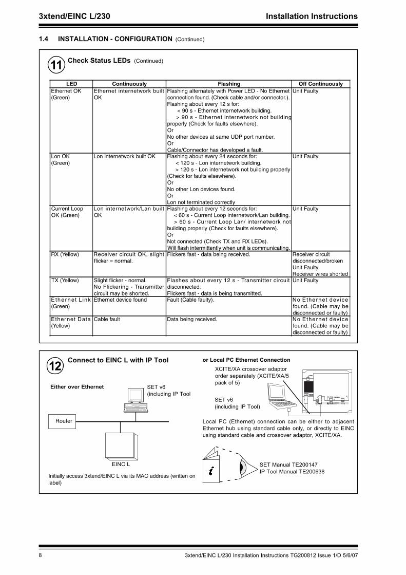
1.4 INSTALLATION - CONFIGURATION (Continued)
Check Status LEDs (Continued)11
12 Connect to EINC L with IP Tool
SET Manual TE200147IP Tool Manual TE200638
EINC L
Router
Either over Ethernet
or Local PC Ethernet Connection
SET v6(including IP Tool
XCITE/XA crossover adaptororder separately (XCITE/XA/5pack of 5)
SET v6(including IP Tool)
Local PC (Ethernet) connection can be either to adjacentEthernet hub using standard cable only, or directly to EINCusing standard cable and crossover adaptor, XCITE/XA.
Initially access 3xtend/EINC L via its MAC address (written onlabel)
LED Continuously Flashing Off ContinuouslyEthernet OK(Green)
Ethernet internetwork builtOK
Flashing alternately with Power LED - No Ethernetconnection found. (Check cable and/or connector.).Flashing about every 12 s for: < 90 s - Ethernet internetwork building. > 90 s - Ethernet internetwork not buildingproperly (Check for faults elsewhere).OrNo other devices at same UDP port number.OrCable/Connector has developed a fault.
Unit Faulty
Lon OK(Green)
Lon internetwork built OK Flashing about every 24 seconds for: < 120 s - Lon internetwork building. > 120 s - Lon internetwork not building properly(Check for faults elsewhere).OrNo other Lon devices found.OrLon not terminated correctly
Unit Faulty
Current LoopOK (Green)
Lon internetwork/Lan builtOK
Flashing about every 12 seconds for: < 60 s - Current Loop internetwork/Lan building. > 60 s - Current Loop Lan/ internetwork notbuilding properly (Check for faults elsewhere).OrNot connected (Check TX and RX LEDs).Will flash intermittently when unit is communicating.
Unit Faulty
RX (Yellow) Receiver circuit OK, slightflicker = normal.
Flickers fast - data being received. Receiver circuitdisconnected/brokenUnit FaultyReceiver wires shorted
TX (Yellow) Slight flicker - normal.No Flickering - Transmittercircuit may be shorted.
Flashes about every 12 s - Transmitter circuitdisconnected.Flickers fast - data is being transmitted.
Unit Faulty
E ther net L ink(Green)
Ethernet device found Fault (Cable faulty). No Ethernet dev icefound. (Cable may bedisconnected or faulty)
Ethernet Data(Yellow)
Cable fault Data being received. No Ethernet dev icefound. (Cable may bedisconnected or faulty)

93xtend/EINC L/230 Installation Instructions TG200812 Issue 1/D 5/6/07
Installation Instructions 3xtend/EINC L/230
1.4 INSTALLATION - CONFIGURATION (Continued)
Configure Addressing Details with IP Tool13 3xtend/EINC L Data Sheet TA200800IP Tool Manual TE200638
The EINC L’s addressing information can be set up automatically (automatic addressing) or manually (manual addressing).When set up automatically the addressing details are obtained from a DHCP server, if a DHCP server is not being used or failsthe EINC L enters link/local mode where it autonegotiates its IP address with other devices on its Ethernet segment. Alternativelythe settings can be specified manually. When automatic addressing is used the EINC L’s IP address may vary, with manualaddressing the IP address is fixed. The addressing details can be viewed or configured using IPTool. The table below describesthe options that must be set up for each addressing mode.
The table below describes the addressing parameters that need to be set up.
Addressing MethodAutomatic Manual
DHCP Link/LocalDHCP Server Required Yes Must not be installed NoWINS Server Required Yes No i f a l l d e vi c e s o n s a m e
subnet, otherwise required.Only required if connection todevices is to be made usinghost names.
DHCP Set to Yes. This is the default. Set to Yes. This is the default. Set to No using IPToolIP Address Set by DHCP server A utonego t i a ted wi th o the r
devices on same subnet.Must be specified using IPTool.It is possible to use a fixed IPaddress on a DHCP systemproviding the DHCP server isset not to allocate the address.
Subnet Mask Set by DHCP server Uses 255.255.0.0 Must be specified using IPToolDefault Router Set by DHCP server N/A Must be specified using IPToolWINS Server Set by DHCP server N/A Must be specified using IPToolHostName Default va lue used. Can be
specified using IPTool.Default value used. Can bespecified using IPTool.
Default value used. Can bespecified using IPTool.
UDP Port Default va lue used. Can bespecified using IPTool.
Default value used. Can bespecified using IPTool.
Default value used. Can bespecified using IPTool.
Identifier Default va lue used. Can bespecified using IPTool.
Default value used. Can bespecified using IPTool.
Default value used. Can bespecified using IPTool.
Internetwork Across Routers Set up host name and subnetmask of remote devices usingIPTool.
Not available Set up host name/IP address,and subnet mask of remotedevices using IPTool.
Virtual CNCs Required S et CNC address and po rtnumber of required vCNCs withIPTool. For vCNCs i n a larmmode also set up the host nameof device to which alarms are tobe sent.
Set CNC address and portnumber of required vCNCs withIPTool. For vCNCs in alarmmode also set up the host nameof device to which alarms are tobe sent.
Set CNC address and portnumber of required vCNCs withIPTool. For vCNCs in a larmmode also set up the IP addressof host name of device to whichalarms are to be sent
Parameter Description When to changeAddressModule
Identifier A 40-character label used to identify the Lan. It defaults to TREND_xx_yy_zz.Where xx, yy, and zz are the last 3 groups of numbers in the MAC address.Range = 40 alphanumeric characters - not /\({;?* characters
When de fault i s notsuitable.
IPNetworkModule
Default Router The IP address of the router to which messages are sent if the destination addressis not on the local subnet. It should be set to the IP address of a router on the samesubnet as the EINC L. It must be specified if the EINC L is to build an internetworkthat spans routers, or if one of the virtual CNCs is to be used by a PC connectedto an Ethernet subnet the other side of a router.When automatic addressing is specified it is obtained from a DHCP server. If thereno DHCP server or it is not operating it is not set.If manual addressing is selected it must be manually defined, in this case it defaultsto 0.0.0.0.Range = 0.0.0.0 to 255.255.255.255
W h e n m a n u a laddressing is beingused.

10 3xtend/EINC L/230 Installation Instructions TG200812 Issue 1/D 5/6/07
3xtend/EINC L/230 Installation Instructions
1.4 INSTALLATION - CONFIGURATION (Continued)
Configure Addressing Details with IP Tool (Continued)133xtend/EINC L Data SheetTA200800IP Tool Manual TE200638
Parameter Description When to changeIPNetworkModule
DHCP Specifies whether automatic or manual addressing is used.When automatic addressing is specified the EINC L's IP address,subnet mask, default router, and WINS server parameters are obtainedfrom a DHCP server. If there no DHCP server or it is not operating theIP address is autonegotiated with the other devices on the same subnet,and the IP subnet mask is set to 255.255.0.0If manual addressing is selected the EINC L's IP address, subnet mask,default router, and WINS server parameters must be manually defined.Range = Yes or No, Yes = DHCP used, Default = Yes.
When addressing mode is tobe changed.Manual addressing can beus e d o n a s ys t e m w i t h aDHCP server provideg theEINC L's address is outsidethe range assigned by theserver
Host Name (read/only) A 15-character string that is registered with the network nameserver for connecting by name rather than IP addresIt defaults to TREND_xx_yy_zz. Where xx, yy, and zz are the last 3 groupsof numbers in the MAC address.Range = 15 alphanumeric characters - not /\({;?* characters
When default is not suitable.
IP Address (read/write) The IP address of the EINC L. The IP address for eachdevice on the Ethernet network must be unique to avoid addressclashes.When automatic addressing is specified it is obtained from a DHCPserver. If there no DHCP server or it is not operating it is autonegotiatedwith other devies on the same subnet.If manual addressing is selected it must be manually defined, in this caseit defaults to 0.0.0.0.Range = 0.0.0.0 to 255.255.255.255
When manual addressing isbeing used.
WINS Server (read/write) Specifies the IP address of the WINS Server.When automatic addressing is specified it is obtained from a DHCPserver. If there no DHCP server or it is not set.If manual addressing is selected it must be manually defined, in this caseit defaults to 0.0.0.0.Range = 0.0.0.0 to 255.255.255.255
When manual addressing isbeing used, and connection todevices using hostnames isrequired.
Subnet Mask (read/write) The subnet mask of the EINC L The subnet mask must bethe same for all devices not separated by routers that are to build Lansor an internetwork. This ensures that they are on the same subnet.When automatic addressing is specified it is obtained from a DHCPserver. If there no DHCP server it is set to 0.0.0.0.If manual addressing is selected it must be manually defined, in this caseit defaults to255.255.255.0.Range = 0.0.0.0 to 255.255.255.255
When manual addressing isbeing used.
UDP Port (read/write)The UDP (User Datagram Protocol) port used by the EINCL to communicate with other IQ system devices over the Ethernetnetwork. All devices used to create an internetwork must use same port.Defaults to 57612.Range = 0 to 65535
When default is not suitablee.g port already being used ormultiple internetworks (sites)required on the same subnet.
RemoteEINCModules
IP Address (read/write) The IP address/host name of the remote device on Ethernet.The host name or IP address of the remote device on Ethernet.Range = 0.0.0.0 to 255.255.255.255. Default=0.0.0.0
If internetwork is to be bui ltacross routers. At least twod e vi c e s f ro m e a c h e a c hsubnet should be specifed.Subnet mask (read/write) The subnet mask for the remote device.Range = 0.0.0.0 to
255.255.255.255 Default=0.0.0.0At least two devices from each each subnet should be specifed. For increased reliability details of additional devicesshould be specified. If automatic addressing is being used the devices must be specified using hostnames, and if manualaddressing is being used the list should contain the devices with the lowest IP addresses. The table must be placed inall devices on the network.
VirtualCNCModules
Alarm IPAddress
The host name or IP address of the alarm target supervisor that isconnected to the Ethernet network if operating in alarm mode. Settingthis up switches the virtual CNC into alarm mode, and prevents the virtualCNC being used as a CNC by a supervisor. 0 will switch the virtual CNCback into supervisor mode. Default=Unused
If the virtual CNC is to be usedto send alarms to a supervisorover Ethernet.
CNC Address The device address of the virtual CNC on EINC L’s Lan. It is set tounused by default, and the virtual CNC will not operate until its addressis set up. It can be set to any valid address (1 to 119 excludingaddresses 2, 3, and 10). 0 will disable the virtual CNC.
If the virtual CNC is to be used.
Port Address The TCP port used by the virtual CNC. It is set unused by default andthen defaults to 10000 plus the cnc address when the cnc address isset up, but can subsequently be changed.Range = 1 to 32767.
If the virtual CNC is to be used.

113xtend/EINC L/230 Installation Instructions TG200812 Issue 1/D 5/6/07
Installation Instructions 3xtend/EINC L/230
� � � � � � � � � � � � � � � � � �
� � � �� �
�
� � � �
� � � � � � � � �
� � � � � � �
� � � � � � � � � � �
� � � � � � � �
� � � � � � � � � � � � � � � � � � � � � � �� � � � � � � � � � � � � � � �
� � �
�
� � �
� � �
� � � � � � � � � � �
� � � � �
� � � � � � � � �
� �
� � � � � � � � � � � � � � � � � � � � � � �
� � �
� � � � �� � � � � � � � � � � � � � � �
� ! � � � � � � " # $ % � &
� � � � � � � � � � � � � � � � � � � � � � �
� � � � �� � � � � � � � � � � � � � � �� ' � � � ( � � � � � � � �
� ! � � � �
� � $ � ) # *
14a Enter configuration mode using SET. The top level
prompt will be displayed as below.b Configure the optional settings the relevant upper
case letter and pressing ENTER. If a value has beenchanged X+ENTER will confirm it and return to thetop menu, whereas Q+ENTER will quit and returnwith the value unchanged. The table on the nextpage describes the settings.
SET Manual TE200147
Configure Optional Settings Using SET
Note that it may be necessary to set up a virtual CNC in theEINC L if one is not available elsewhere on the network.
3xtend/EINC L Data Sheet TA200800
1.4 INSTALLATION - CONFIGURATION (Continued)
Note that if required the parameters configured using IP Tool can also be configured in the same way.
Write on Label15� �
� � � � � � 00.10.70.00.UD.BB
� � �
S/No:Q3B____X73010003
� ! � � � � Location
� � � � � � 00.10.70.00.UD.BB
S/No:Q3B____X73010003XTND -400007096
� ! � � � �
� � $ � ) # *
recommendede.g. location/identifier
IP Address, Location, Lan, address
retemaraP noitpircseDsserddA
eludoMmralAnaL
sserddAtinehwkrowtenpooltnerrucehtybdetarenegsmralarofsserddaecivedtegratmralaehT)etirw/daer(
0.)01dna,3,2sesserddagnidulcxe911ot1(sserddadilavynaottesebnactI.naLasagnitareposi.dettimsnartgniebsmralaehtspots
mralAnaLnaL
gnitarepositinehwkrowtenpooltnerrucehtybdetarenegsmralarofrebmunnaLtegratehT)etirw/daer(ehtspots0.)01dna,3,2sesserddagnidulcxe911ot1(sserddadilavynaottesebnactI.naLasa
.dettimsnartgniebsmralamralA
egaugnaL,hsidewS=3,hsinniF=2,hsinapS=1,hsilgnE=0.smralakrowtenehtrofdesuegaugnalehT)etirw/daer(
.hcnerF=9,eseugutroP=8,nailatI=7,namreG=6,hsinaD=5,naigewroN=4emaNtsoH emanybgnitcennocrofrevresemankrowtenehthtiwderetsigersitahtgnirtsretcarahc51A)etirw/daer(
.sserddaPInahtrehtarkrowtenretnI
mralAsserddA
sserddadilavynaottesebnactI.smralakrowtenretnirofsserddaecivedtegratmralaehT)etirw/daer(.dettimsnartgniebsmralaehtspots0.)01dna,3,2sesserddagnidulcxe911ot1(
krowtenretnInaLmralA
1(sserddadilavynaottesebnactI.smralakrowtenretnirofrebmunnaLtegratmralaehT)etirw/daer(.dettimsnartgniebsmralaehtspots0.)01dna,3,2sesserddagnidulcxe911ot
elbasiDevilACNCv
smralA
,oNroseY=egnaR.sCNClautrivybdetarenegsmraladaedeciveddna,enil-noecivedselbasid/selbanE.oN=tluafeD.delbasidsmrala=seY
etomeRseciveD
dneSetomeR
stsacdaorB
krowtenretniehtdliubotdesuerasegassemdetceridrosegassemtsacdaorbetomerrehtehwseificepS.sretuorssorca
sretuorssorcakrowtenretniehtdliubotdesusegassemeht)seY(segassemtsacdaorbesuottesfIetomerehtnosecivedllaotegassemtsacdaorbagnitseuqerretuortluafedehtottneseblliw
.eludomehtnideificepsecivedetomerehtsallewsatenbuss’ecivedsretuorssorcakrowtenretniehtdliubotdesusegassemeht)oN(segassemtsacdaorbesuottontesfI
.eludomehtnideificepsecivedehtot)gnigassemtceridyb(tnesebylnolliw.delbasidgnigassemtsacdaorbetomerevahsretuorehtfiffodenrutebylnodluohsnoitposihT
deretneebdluohstenbushcaemorfelbissopsas’ecivedynamsafosliated,ffodenrutsignitsacdaorbfI.eruliafafotneveehtnitliubebotkrowtenretniehtelbaneotelbatsecivedetomerehtni
etadpUetomeRseciveD
ruoyypoCCNIEetomer
rehtoottsilsCNIE)N/Y(
tsilniCNIEdnasL/CNIEhtiwstenbuslladnatenbuslacolottsilscniEetomerehtseipoC
resUseludoM
NIP tnesebtsumro,yalpsidamorfnogolotresuehtybderetneebtsumtahtrebmuntigid-4ehT)etirw/daer(.egnahcaesirohtuaotrosivrepus/lootayb
emiTeludoM
emiT .)dekcabyrettabtoneton(emitdnaetadehT
etadpUtsiL
ruoyypoCCNIEetomer
rehtoottsil)N/Y(sCNIE
tsilniCNIEdnasL/CNIEhtiwstenbuslladnatenbuslacolottsilscniEetomerehtseipoC

12 3xtend/EINC L/230 Installation Instructions TG200812 Issue 1/D 5/6/07
3xtend/EINC L/230 Installation Instructions
12345678910
Check Communications
� # &
+ � & � " , � � ) & $ � - � � . /
& $ ) � & ) $ 0 � � 1
+ � & � " , � � ) & $ � - � � . /
& $ ) � & ) $ 0 � � 1
+ � & � 2 $ 3 ) � & ) $ /
& $ ) � & ) $ 0 � � 1
+ � & � � � � /
EINC
2 � �
4 5 6
27 8 9
310 11 12
4
13 14 15
5
16 17 18
6
19 20 21
7
22 23 24
825 26 27
928 29 30
10+ 0+ 0 + 0 + 0 + 0 + 0+ 0+ 0+ 0
1 2 3
1+ 0
0 V24 V
24 V 34 35 36
12
37 38 39
13
40 41 42
14A
31 32 33P
11
43 44 45
15
46 47 48
16100-240 V
OK RXP 0 P 0 P 0P 0 P 0 P 0
OK
Tx Rx
230 V1 2 3 4 5 6 83 4 5
7 9 10 1124 V 24V
AC24VAC
24VAC
� �
� # &
+ � & � " , � � ) & $ � - � � . /
� �
2 � � � �
� # &
+ � & � " , � � ) & $ � - � � . /
� # &
+ � & � " , � � ) & $ � - � � . /
2 � � � �
& $ ) � & ) $ 0 � � 1
+ � & � 2 $ 3 ) � & ) $ /
& $ ) � & ) $ 0 � � 1
+ � & � � � � /
EINC
2 � �
4 5 6
27 8 9
310 11 12
4
13 14 15
516 17 18
619 20 21
7
22 23 24
825 26 27
928 29 30
10+ 0+ 0 + 0 + 0 + 0 + 0+ 0+ 0+ 0
1 2 3
1+ 0
0 V24 V
24 V 34 35 36
12
37 38 39
13
40 41 42
14A
31 32 33P
11
43 44 45
15
46 47 48
16100-240 V
OK RXP 0 P 0 P 0P 0 P 0 P 0
OK
Tx Rx
230 V1 2 3 4 5 6 83 4 5
7 9 10 1124 V 24V
AC24VAC
24VAC
� �
1.4 INSTALLATION - CONFIGURATION (Continued)
Tear off Label Strip16XTEND -400007096� � $ � ) # *
� �
� � � � � � 00.10.70.00.UD.BB
� � �
S/No:
� ! � � � � Location
� � � � � � 00.10.70.00.UD.BB
S/No:Q3B____X73010003
� ! � � � �
� � � � � � 00.10.70.00.UD.BB S/No:Q3B____X73010003
� ! � � � � Location
18
If address=>100
If address <100
� # &
+ � & � " , � � ) & $ � - � � . /
� # &
+ � & � " , � � ) & $ � - � � . /
& $ ) � & ) $ 0 � � 1
+ � & � 2 $ 3 ) � & ) $ /
& $ ) � & ) $ 0 � � 1
+ � & � � � � /
EINC
2 � �
4 5 6
27 8 9
310 11 12
4
13 14 15
516 17 18
619 20 21
7
22 23 24
825 26 27
928 29 30
10+ 0+ 0 + 0 + 0 + 0 + 0+ 0+ 0+ 0
1 2 3
1+ 0
0 V24 V
24 V 34 35 36
12
37 38 39
13
40 41 42
14A
31 32 33P
11
43 44 45
15
46 47 48
16100-240 V
OK RXP 0 P 0 P 0P 0 P 0 P 0
OK
Tx Rx
230 V1 2 3 4 5 6 83 4 5
7 9 10 1124 V 24V
AC24VAC
24VAC
� �2 � � � �
� # &
+ � & � " , � � ) & $ � - � � . /
� # &
+ � & � " , � � ) & $ � - � � . /
& $ ) � & ) $ 0 � � 1
+ � & � 2 $ 3 ) � & ) $ /
& $ ) � & ) $ 0 � � 1
+ � & � � � � /
EINC
2 � �
4 5 6
27 8 9
310 11 12
413 14 15
5
16 17 18
619 20 21
7
22 23 24
825 26 27
928 29 30
10+ 0+ 0 + 0 + 0 + 0 + 0+ 0+ 0+ 0
1 2 3
1+ 0
0 V24 V
24 V 34 35 36
12
37 38 39
13
40 41 42
14A
31 32 33P
11
43 44 45
15
46 47 48
16100-240 V
OK RXP 0 P 0 P 0P 0 P 0 P 0
OK
Tx Rx
230 V1 2 3 4 5 6 83 4 5
7 9 10 1124 V 24V
AC24VAC
24VAC
� �2 � � � �
� # &
+ � & � " , � � ) & $ � - � � . /
& $ ) � & ) $ 0 � � 1
+ � & � " , � � ) & $ � - � � . /
& $ ) � & ) $ 0 � � 1
+ � & � 2 $ 3 ) � & ) $ /
& $ ) � & ) $ 0 � � 1
+ � & � � � � /
EINC
2 � �
4 5 6
27 8 9
310 11 12
4
13 14 15
5
16 17 18
6
19 20 21
7
22 23 24
825 26 27
928 29 30
10+ 0+ 0 + 0 + 0 + 0 + 0+ 0+ 0+ 0
1 2 3
1+ 0
0 V24 V
24 V 34 35 36
12
37 38 39
13
40 41 42
14A
31 32 33P
11
43 44 45
15
46 47 48
16100-240 V
OK RXP 0 P 0 P 0P 0 P 0 P 0
OK
Tx Rx
230 V1 2 3 4 5 6 83 4 5
7 9 10 1124 V 24V
AC24VAC
24VAC
� �
� # &
+ � & � " , � � ) & $ � - � � . /
� �
2 � � � �
� # &
+ � & � " , � � ) & $ � - � � . /
& $ ) � & ) $ 0 � � 1
+ � & � " , � � ) & $ � - � � . /
& $ ) � & ) $ 0 � � 1
+ � & � 2 $ 3 ) � & ) $ /
& $ ) � & ) $ 0 � � 1
+ � & � � � � /
EINC
2 � �
4 5 6
27 8 9
310 11 12
4
13 14 15
516 17 18
619 20 21
7
22 23 24
825 26 27
928 29 30
10+ 0+ 0 + 0 + 0 + 0 + 0+ 0+ 0+ 0
1 2 3
1+ 0
0 V24 V
24 V 34 35 36
12
37 38 39
13
40 41 42
14A
31 32 33P
11
43 44 45
15
46 47 48
16100-240 V
OK RXP 0 P 0 P 0P 0 P 0 P 0
OK
Tx Rx
230 V1 2 3 4 5 6 83 4 5
7 9 10 1124 V 24V
AC24VAC
24VAC
� �
� # &
+ � & � " , � � ) & $ � - � � . /
� �
2 � � � �
19 Check Virtual CNCs Virtual CNCs in Alarm Mode
2 $ 3 ) � & ) $
CNCBCNCA
EINC L
CNCDCNCC
SET, or 963using permanent connection
CNC in Supervisor mode
CNCFCNCE CNCHCNCG
Virtual CNCs in Supervisor Mode
2 $ 3 ) � & ) $
CNCBCNCA
EINC L
CNCDCNCC
963using temporary connection
CNC in Alarm mode
CNCFCNCE CNCHCNCG
Alarm from system sent to VCNC
Replace Cover17 a
b
133xtend/EINC L/230 Installation Instructions TG200812 Issue 1/D 5/6/07
Installation Instructions 3xtend/EINC L/230
� � � � � � � � � � � � � � � � � �
� � � �� �
�
� � � �
� � � � � � � � �
� � � � � � �
� � � � � � � � � � �
� � � � � � � �
� � � � � � � � � � � � � � � � � � � � � � �� � � � � � � � � � � � � � � �
� � �
�
� � �
� � �
� � � � � � � � � � �
� � � � �
� � � � � � � � �
� � � � � � � � � � � � � � � � � �
� � � �� �
�
� � � �
� � � � � � � � �
� � � � � � �
� � � � � � � � � � �
� � � � � � � �
� � � � � � � � � � � � � � � � � � � � � � �� � � � � � � � � � � � � � � �
� � �
�
� � �
� � �
� � � � � � � � � � �
� � � � �
� � � � � � � � �
1234567891012345678910
O
I
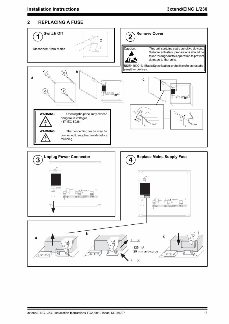
Switch Off1
2 REPLACING A FUSE
Remove Cover2
WARNING: Opening the panel may exposedangerous voltages.417-IEC-5036
Caution: This unit contains static sensitive devices.Suitable anti-static precautions should betaken throughout this operation to preventdamage to the units.
ab
c
WARNING: The connecting leads may beconnected to supplies. Isolate beforetouching.
BS EN100015/1 Basic Specification: protection of electrostaticsensitive devices.
Replace Mains Supply Fuse4
ab c
Unplug Power Connector3
125 mA20 mm anti-surge
Disconnect from mains
14 3xtend/EINC L/230 Installation Instructions TG200812 Issue 1/D 5/6/07
3xtend/EINC L/230 Installation Instructions
12345678910
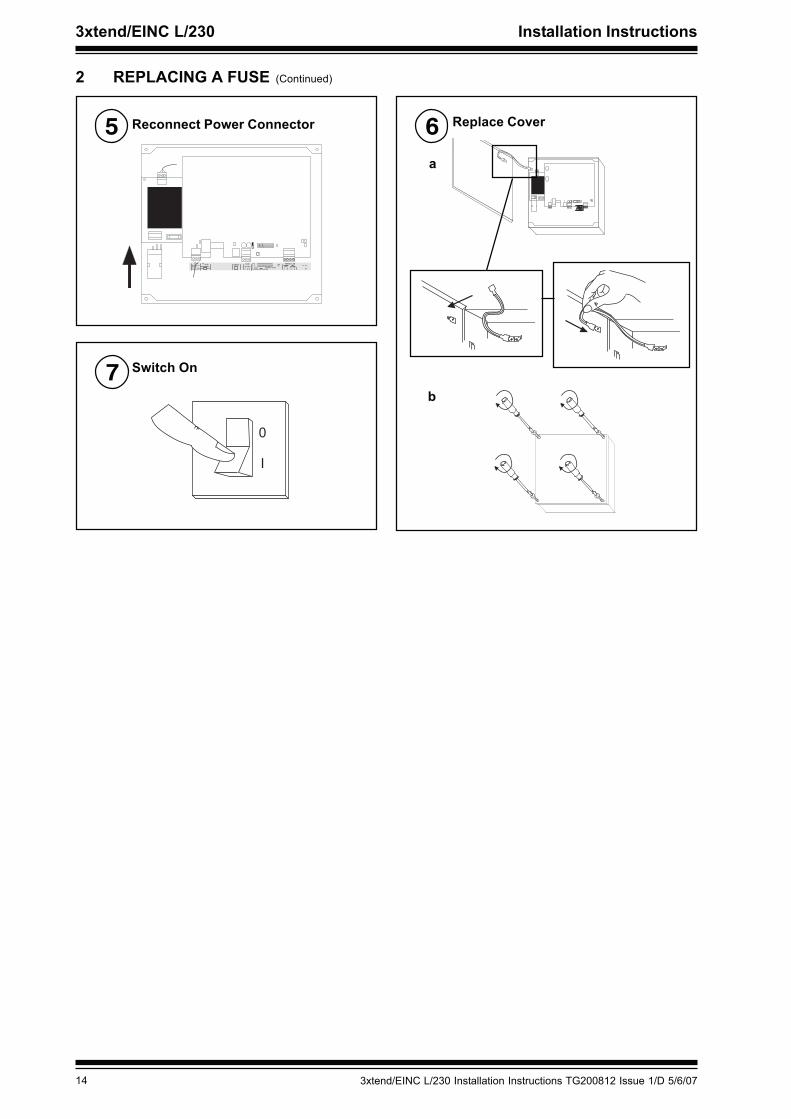
2 REPLACING A FUSE (Continued)
Replace Cover6a
b
�
�
Switch On7
Reconnect Power Connector5
� � � � � � � � � � � � � � � � � �
� � � �� �
�
� � � �
� � � � � � � � �
� � � � � � �
� � � � � � � � � � �
� � � � � � � �
� � � � � � � � � � � � � � � � � � � � � � �� � � � � � � � � � � � � � � �
� � �
�
� � �
� � �
� � � � � � � � � � �
� � � � �
� � � � � � � � �
153xtend/EINC L/230 Installation Instructions TG200812 Issue 1/D 5/6/07
Installation Instructions 3xtend/EINC L/230
3 END USER LICENCE AGREEMENTEULA Terms
• You have acquired a 3xtend/EINC L (“Device”) that includes software licensed by Trend Control Systems Ltd from one or moresoftware licensors (“Trend Control Systems Ltd Software Suppliers”). Such software products, as well as associated mediaprinted materials and “online” or electronic documentation (“SOFTWARE”) are protected by international intellectual propertylaws and treaties. The SOFTWARE is licensed, not sold. All rights reserved.”
• IF YOU DO NOT AGREE TO THIS END USER LICENSE AGREEMENT (“EULA”), DO NOT USE THE DEVICE OR COPY THESOFTWARE. INSTEAD, PROMPTLY CONTACT TREND CONTROL SYSTEMS LTD FOR INSTRUCTIONS ON RETURN OFTHE UNUSED DEVICE(S) FOR A REFUND. ANY USE OF THE SOFTWARE INCLUDING BUT NOT LIMITED TO USE ON THEDEVICE WILL CONSTITUTE YOUR AGREEMENT TO THE EULA (OR RATIFICATION OF ANY PREVIOUS CONSENT).
• GRANT OF SOFTWARE LICENSE. This EULA grants you the following license:
• You may use the SOFTWARE only on the DEVICE
• NOT FAULT TOLERANT. THE SOFTWARE IS NOT FAULT TOLERANT. TREND CONTROL SYSTEMS LTD HASINDEPENDENTLY DETERMINED HOW TO USE THE SOFTWARE IN THE DEVICE, AND TREND CONTROL SYSTEMSLTD’S SOFTWARE SUPPLIERS HAS RELIED UPON TREND CONTROL SYSTEMS LTD TO CONDUCT SUFFICIENTTESTING TO DETERMINE THAT THE SOFTWARE IS SUITABLE FOR SUCH USE.
• NO WARRANTIES FOR THE SOFTWARE. THE SOFTWARE is provided “AS IS” and with all faults. THE ENTIRE RISKAS TO SATISFACTORY QUALITY, PERFORMANCE, ACCURACY, AND EFFORT (INCLUDING LACK OF NEGLIGENCE)IS WITH YOU. ALSO, THERE IS NO WARRANTY AGAINST INTERFERENCE WITH YOUR ENJOYMENT OF THESOFTWARE OR AGAINST INFRINGEMENT. IF YOU HAVE RECEIVED ANY WARRANTIES REGARDING THE DEVICEOR THE SOFTWARE, THOSE WARRANTIES DO NOT ORIGINATE FROM, AND ARE NOT BINDING ON, TRENDCONTROL SYSTEMS LTD’S SOFTWARE SUPPLIERS.
• Note on Java Support. The SOFTWARE may contain support for programs written in Java. Java technology is not faulttolerant and is not designed, manufactured, or intended for use or resale as online control equipment in hazardousenvironments requiring fail-safe performance, such as in the operation of nuclear facilities, aircraft navigation or communicationsystems, air traffic control, direct life support machines, or weapons systems, in which the failure of Java technology couldlead directly to death, personal injury, or severe physical or environmental damage. Sun Microsystems, Inc. has contractuallyobligated Trend Control Systems Ltd’s software suppliers to make this disclaimer.
• No Liability for Certain Damages. EXCEPT AS PROHIBITED BY LAW, TREND CONTROL SYSTEMS LTD’S SOFTWARESUPPLIERS SHALL HAVE NO LIABILITY FOR ANY INDIRECT, SPECIAL, CONSEQUENTIAL OR INCIDENTALDAMAGES ARISING FROM OR IN CONNECTION WITH THE USE OR PERFORMANCE OF THE SOFTWARE. THISLIMITATION SHALL APPLY EVEN IF ANY REMEDY FAILS OF ITS ESSENTIAL PURPOSE. IN NO EVENT SHALLTREND CONTROL SYSTEMS LTD’S SOFTWARE SUPPLIERS BE LIABLE FOR ANY AMOUNT IN EXCESS OF U.S.TWO HUNDRED FIFTY DOLLARS (U.S.$250.00).
• Limitations on Reverse Engineering, Decompilation, and Disassembly. You may not reverse engineer, decompile,or disassemble the SOFTWARE, except and only to the extent that such activity is expressly permitted by applicable lawnotwithstanding this limitation.
• SOFTWARE TRANSFER ALLOWED BUT WITH RESTRICTIONS. You may permanently transfer rights under this EULAonly as part of a permanent sale or transfer of the Device, and only if the recipient agrees to this EULA. If the SOFTWAREis an upgrade, any transfer must also include all prior versions of the SOFTWARE.
16 3xtend/EINC L/230 Installation Instructions TG200812 Issue 1/D 5/6/07
3xtend/EINC L/230 Installation Instructions
Manufactured for and on behalf of the Environmental and Combustion Controls Division of Honeywell Technologies Sàrl, Ecublens, Route du Bois37,Switzerland by its Authorized Representative.
Trend Control Systems Ltd reserves the right to revise this publication from time to time and make changes to the content hereof withoutobligation to notify any person of such revisions or changes.
Trend Control Systems LimitedP.O. Box 34, Horsham, West Sussex, RH12 2YF, UK. Tel:+44 (0)1403 211888 Fax:+44 (0)1403 241608 www. trend-controls.comTrend Control Systems USA6670 185th Avenue NE, Redmond, Washington 98052, USA. Tel: (425) 897 3900, Fax: (425)869-8445 www. trend-controls.com
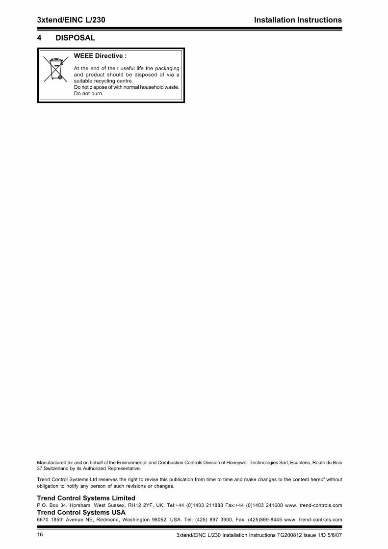
WEEE Directive :
At the end of their useful life the packagingand product should be disposed of via asuitable recycling centre.Do not dispose of with normal household waste.Do not burn.
4 DISPOSAL