3X3-03 Free-Way Switch Schematic - StewMac 16.0 39.1 10.8 11.0 Model No:-3X3-03 Free-Way Switch...
13
POSITION 2 POSITION 3 POSITION 6 POSITION 5 POSITION 1 POSITION 4 4 1 2 3 5 6 32.0 24.0 17.3 10.0 12.0 16.0 39.1 10.8 11.0 Schematic Model No:- 3X3-03 Free-Way Switch 3X3-03 Schematic : Last Updated June 2013 'Make Before Break' action in all transitions, except Position 2 to Position 5 where N1 to M2 is 'Break Before Make' on both A & B Two circuits 'A' & 'B' have commons 'CA' and 'CB' each connecting to: B1,B2,M1,M2,N1,N2 in varying switch positions. (sometimes in combination) ELECTRICAL FUNCTION A & B side switching differs: 'A' combines B1+B2/N1+N2 'B' isolates B1+B2/N1+N2. 'GD' is 'ground' or 'earth'. Top View of Switch Reverse View of Switch Reverse View of Switch Reverse View of Switch Reverse View of Switch Reverse View of Switch Reverse View of Switch ELECTRICAL TRANSITION
-
Upload
hoangkhuong -
Category
Documents
-
view
221 -
download
3
Transcript of 3X3-03 Free-Way Switch Schematic - StewMac 16.0 39.1 10.8 11.0 Model No:-3X3-03 Free-Way Switch...

POSITION 2
POSITION 3POSITION 6
POSITION 5
POSITION 1POSITION 4
4 1
2
3
5
6
32.024.0
17.310.0
12.0
16.0
39.1
10.8
11.0
SchematicModel No:- 3X3-03 Free-Way Switch
3X3-03 Schematic : Last Updated June 2013
'Make Before Break' actionin all transitions, exceptPosition 2 to Position 5
where N1 to M2 is 'BreakBefore Make' on both A & B
Two circuits 'A' & 'B' havecommons 'CA' and 'CB'
each connecting to:B1,B2,M1,M2,N1,N2
in varying switch positions.(sometimes in combination)
ELECTRICAL FUNCTION
A & B side switching differs:'A' combines B1+B2/N1+N2'B' isolates B1+B2/N1+N2.'GD' is 'ground' or 'earth'.
Top View of Switch Reverse View of Switch
Reverse View of SwitchReverse View of Switch
Reverse View of Switch
Reverse View of Switch Reverse View of Switch
ELECTRICAL TRANSITION
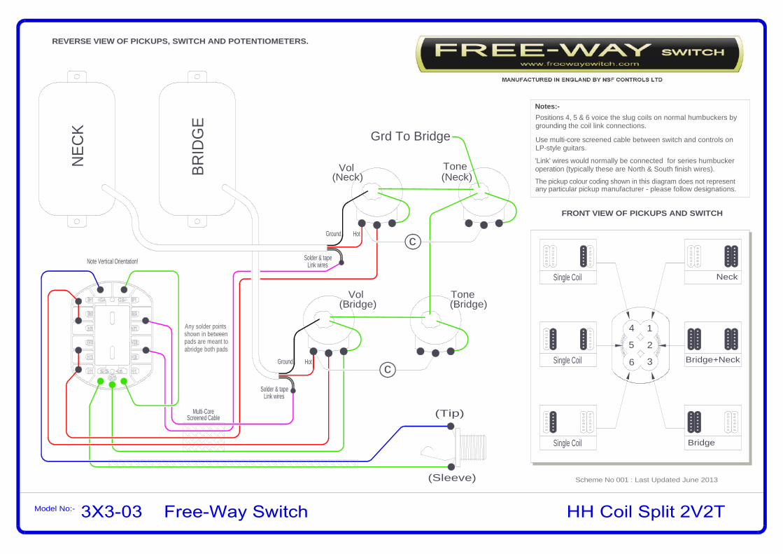
HH Coil Split 2V2TModel No:-
NEC
K
REVERSE VIEW OF PICKUPS, SWITCH AND POTENTIOMETERS.
Tone
c
Vol Tone
BRID
GE
(Tip)
Grd To Bridge
Vol(Neck) (Neck)
(Bridge)(Bridge)
c
FRONT VIEW OF PICKUPS AND SWITCH
Neck
Bridge+Neck
Bridge
4 1
2
3
5
6
Single Coil
Single Coil
Single Coil
Notes:-
(Sleeve)
Multi-CoreScreened Cable
Use multi-core screened cable between switch and controls onLP-style guitars.
Positions 4, 5 & 6 voice the slug coils on normal humbuckers bygrounding the coil link connections.
Note Vertical Orientation!
Solder & tapeLink wires
Solder & tapeLink wires
'Link' wires would normally be connected for series humbuckeroperation (typically these are North & South finish wires).
HotGround
HotGround
any particular pickup manufacturer - please follow designations.The pickup colour coding shown in this diagram does not represent
Scheme No 001 : Last Updated June 2013
3X3-03 Free-Way Switch
Any solder pointsshown in betweenpads are meant toabridge both pads

HHH 3V/1TModel No:- 3X3-03 Free-Way Switch
Neck
Bridge+Neck
Bridge
4 1
2
3
5
6
Neck & Middle
Middle
Bridge & Middle
BRID
GE
MID
DLE
NEC
K
c
Grd To Bridge
Vol(Neck)
Vol(Mid)
OptionalDPDTSwitch
(Master)(Bridge)Vol Tone
REVERSE VIEW OF PICKUPS, SWITCH AND POTENTIOMETERS.
FRONT VIEW OF PICKUPS AND SWITCH
Optional Push/Pull Pot affects position 5 only: push in for middlepickup only, pull out for Neck+Middle+Bridge pickups. Omit push/pull pot and dotted wires for middle pickup only in position 5.
(Sleeve)
(Tip)
Multi-CoreScreened Cable
Use multi-core screened cable between switch and controls onLP-style guitars.
For Humbucker guitars, middle PU is normally reverse phase.
(or option for 3 x pu.s)
Note Vertical Orientation!
HotGround
HotGround HotGround
(M)
(N)
(B)
Notes:-
any particular pickup manufacturer - please follow designations.The pickup colour coding shown in this diagram does not represent
Scheme No 002 : Last Updated June 2013and the Bridge Vol mutes the entire output in position 2,3 & 6. The Middle Vol blends in the Middle Pickup in positions 4, 5 & 6.Note: Neck & Bridge Vol controls are 'master' controls in this diagram, so that the Neck Vol mutes the entire output in positions 1,2 & 4
If more scope for individual pickup blending is preferred, then reverse hot and wiper connections at B Vol and N Vol pots.
Any solder pointsshown in betweenpads are meant toabridge both pads

HHH 2V/2TModel No:-
Neck
Bridge+Neck
Bridge
4 1
2
3
5
6
Neck & Middle
Middle
Bridge & Middle
BRID
GE
MID
DLE
NEC
K
Vol(Neck)
(Bridge)Vol
REVERSE VIEW OF PICKUPS, SWITCH AND POTENTIOMETERS.
FRONT VIEW OF PICKUPS AND SWITCH
Multi-CoreScreened Cable
Use multi-core screened cable between switch and controls onLP-style guitars.
For Humbucker guitars, middle PU is normally reverse phase.
Note Vertical Orientation!
Hot
Ground
Hot
Notes:-
any particular pickup manufacturer - please follow designations.The pickup colour coding shown in this diagram does not represent
(Tip)
(Sleeve)
Tone
c
(Neck)
c
Tone(Bridge)
Grd To Bridge
(Controlled by Bridge V+T)
(Controlled by Bridge V+T)
(Controlled by Neck V+T)
Ground
GroundHot
pickup assigned to logical Vol/Tone controls in positions 4-6.Vol/Tone controls work as normal in positions 1-3. Middle
Scheme No 003 : Last Updated June 2013
3X3-03 Free-Way Switch
Any solder pointsshown in betweenpads are meant toabridge both pads

HH Vol/Tone Bypass 2V/2TModel No:-
Tone
c
Vol Tone
Grd To Bridge
Vol(Neck) (Neck)
(Bridge)(Bridge)
c
BRID
GE
NEC
K
REVERSE VIEW OF PICKUPS, SWITCH AND POTENTIOMETERS.
FRONT VIEW OF PICKUPS AND SWITCH
Neck
Bridge+Neck
Bridge
4 1
2
3
5
6
DIRECT
DIRECT
DIRECT
Notes:-
(Tip)
(Sleeve)
Multi-CoreScreened Cable
Use multi-core screened cable between switch and controls onLP-style guitars.
Positions 4, 5 & 6 entirely bypass vol and tone controls,connecting pickups directly to the output.
Note Vertical Orientation!
HotGround
HotGround
any particular pickup manufacturer - please follow designations.The pickup colour coding shown in this diagram does not represent
Hear your pickups wide open for lead, set up precise levels usingvol/tone controls for rhythm, or use as a mute-switch.
Scheme No 004 : Last Updated June 2013
3X3-03 Free-Way Switch
Any solder pointsshown in betweenpads are meant toabridge both pads

HH Piezo 2V/2TModel No:-
Tone
c
Vol Tone
BRID
GE
NEC
K Grd To Bridge
Vol(Neck) (Neck)
(Bridge)(Bridge)
c
(Sleeve)
(Tip)
REVERSE VIEW OF PICKUPS, SWITCH AND POTENTIOMETERS.
(Sleeve)
(Tip)M
AG
PIE
ZO
Neck
Bridge+Neck
Bridge
4 1
2
3
5
6
+ Piezo
FRONT VIEW OF PICKUPS AND SWITCH
+ Piezo
+ Piezo
PIEZOMODULE
Notes:-
Use multi-core screened cable between switch and controls onLP-style guitars.
For 'piezo only' (no Mag.s) in position 5, unlink Neck 'Hot' fromM2 only and then connect M2 only to 'ground'.
(or option for Piezo only)
Multi-CoreScreened Cable
Positions 4, 5 & 6 enable output from piezo system,(piezo output is connected to ground in positions 1, 2 & 3).
Piezo controls may replace Mag Vol/Tone controls as preferred.
Note Vertical Orientation!Solder & tape Link wires
Solder & tape Link wires
'Link' wires would normally be connected for series humbuckeroperation (typically these are North & South finish wires).
HotGround
HotGround
any particular pickup manufacturer - please follow designations.The pickup colour coding shown in this diagram does not represent
Scheme No 005 : Last Updated June 2013
3X3-03 Free-Way Switch
Any solder pointsshown in betweenpads are meant toabridge both pads

HH Phase & Single Coils 2V/2TModel No:-
Tone
c
BRID
GE
NEC
K Grd To Bridge
Vol(Neck) (Neck)
c
REVERSE VIEW OF PICKUPS, SWITCH AND POTENTIOMETERS.
FRONT VIEW OF PICKUPS AND SWITCH
Neck
Bridge+Neck
Bridge
4 1
2
3
5
6
In Series / Out Phase
Vol Tone(Bridge)(Bridge)
Notes:-
(Tip)
(Sleeve)
Multi-CoreScreened Cable
Use multi-core screened cable between switch and controls onLP-style guitars.
Single Coils / Parallel
Single Coil
Note Vertical Orientation! Solder & tapeLink wires
Solder & tapeLink wires
Solder & tapeGround wires
'Ground' wires (typically South Start wires) from either pickupsrequire to be shielded in this scheme as shown.'Link' wires would normally be connected for series humbuckeroperation (typically these are North & South finish wires).
Hot
Hot
any particular pickup manufacturer - please follow designations.The pickup colour coding shown in this diagram does not represent
Scheme No 006 : Last Updated June 2013
3X3-03 Free-Way Switch
Any solder pointsshown in betweenpads are meant toabridge both pads

HH Hum + S/Coil Combinations 2V/2TModel No:-
REVERSE VIEW OF PICKUPS, SWITCH AND POTENTIOMETERS.
Tone
c
Vol Tone
BRID
GE
NEC
K Grd To Bridge
Vol(Neck) (Neck)
(Bridge)(Bridge)
c
Neck
Bridge+Neck
Bridge
4 1
2
3
5
6
FRONT VIEW OF PICKUPS AND SWITCH
Notes:-
(Tip)
(Sleeve)
Multi-CoreScreened Cable
Use multi-core screened cable between switch and controls onLP-style guitars.
Note Vertical Orientation! Solder & tapeLink wires
Solder & tapeLink wires
HotGround
HotGround
'Link' wires would normally be connected for series humbuckeroperation (typically these are North & South finish wires).
S/C + Hum
Single Coils / Parallel
Hum + S/C
any particular pickup manufacturer - please follow designations.The pickup colour coding shown in this diagram does not represent
Scheme No 007 : Last Updated June 2013
3X3-03 Free-Way Switch
Any solder pointsshown in betweenpads are meant toabridge both pads

HH Diagonal Coil Split 2V/2TModel No:-
REVERSE VIEW OF PICKUPS, SWITCH AND POTENTIOMETERS.
Tone
c
Vol Tone
BRID
GE
NEC
K
Vol(Neck) (Neck)
(Bridge)(Bridge)
c
Neck S/C
Bridge+Neck
Bridge
4 1
2
3
5
6
FRONT VIEW OF PICKUPS AND SWITCH
Grd To Bridge
Notes:-
(Tip)
(Sleeve)
Multi-CoreScreened Cable
Use multi-core screened cable between switch and controls onLP-style guitars.
Neck
Bridge+Neck
Bridge S/C
Note Vertical Orientation! Solder & tapeLink wires
Solder & tapeLink wires
HotGround
HotGround
'Link' wires would normally be connected for series humbuckeroperation (typically these are North & South finish wires).
any particular pickup manufacturer - please follow designations.The pickup colour coding shown in this diagram does not represent
Scheme No 008 : Last Updated June 2013
3X3-03 Free-Way Switch
Any solder pointsshown in betweenpads are meant toabridge both pads

HH Mute Switch 2V2TModel No:-
NEC
K
REVERSE VIEW OF PICKUPS, SWITCH AND POTENTIOMETERS.
Tone
c
Vol Tone
BRID
GE
(Tip)
Grd To Bridge
Vol(Neck) (Neck)
(Bridge)(Bridge)
c
FRONT VIEW OF PICKUPS AND SWITCH
Bridge
Notes:-
(Sleeve)
Multi-CoreScreened Cable
Use multi-core screened cable between switch and controls onLP-style guitars.
Positions 1, 2 & 3 select Neck/Both/Bridge Humbuckers andpositions 4,5 & 6 mute the output by connecting to ground.
Solder & tapeLink wires
Solder & tapeLink wires
HotGround
HotGround
any particular pickup manufacturer - please follow designations.The pickup colour coding shown in this diagram does not represent
Scheme No 009 : Last Updated June 2013
1
56
23
4
NeckBridge+Neck
Mute Mute Mute
Switch orientation shown to suit mute-switching on LP style guitar.
'Link' wires would normally be connected for series humbuckeroperation (typically these are North & South finish wires).
3X3-03 Free-Way Switch
Any solder pointsshown in betweenpads are meant toabridge both pads

HSH 1V/1TModel No:-
Neck
Bridge+Neck
Bridge
4 1
2
3
5
6
REVERSE VIEW OF PICKUPS, SWITCH AND POTENTIOMETERS.
FRONT VIEW OF PICKUPS AND SWITCH
BRID
GE
NEC
K
MID
DLE
'Hot
'
'Gro
und'
134
(SH
IELD
)
2134
(SH
IELD
)
2
Vol Tone
(Sleeve)
(Tip)
c
Grd To Bridge
Note Vertical Orientation!
Single Coil
Single Coil
Single Coil
SOUTH Finish wireNORTH Finish wireNORTH Start wire
SOUTH Start wire
12
43
any particular pickup manufacturer - please follow key.
SN
HUMBUCKER COLOUR KEY
The colour coding or magnetic polarity shown here does not represent
positions 4, 5 & 6 are like the middle positions of a 5-way selector.Positions 1, 2 & 3 are standard neck/both/bridge humbucker settings,
Notes:-
S N
Scheme No 010 : Last Updated June 2013
3X3-03 Free-Way Switch
Any solder pointsshown in betweenpads are meant toabridge both pads
connection to 'CB') this will select 3 x single coils in position 5As an alternative, connect both 'CA' to 'CB' to vol pot. (remove grd.
and the middle + outer humbucker coils in positions 4 and 6.

Model No:-
REVERSE VIEW OF PICKUPS, SWITCH AND POTENTIOMETERS.
FRONT VIEW OF PICKUPS AND SWITCH
Neck
Bridge+Neck
Bridge
4 1
2
3
5
6
Single Coil
Single Coil
Single Coil
BRID
GE
NEC
K
MID
DLE
'Hot
'
'Gro
und'
134
(SH
IELD
)
2
Vol Tone
(Sleeve)
(Tip)
c
Grd To Bridge
'Hot
'
'Gro
und'
Note Vertical Orientation!
HSS 1V/1T
any particular pickup manufacturer - please follow key.SNThe colour coding or magnetic polarity shown here does not represent
SOUTH Finish wireNORTH Finish wireNORTH Start wire
SOUTH Start wire
12
43
HUMBUCKER COLOUR KEYNotes:-
is tapped in position 2). Positions 4, 5 & 6 are like the middlePositions 1, 2 & 3 are neck/both/bridge settings (where the humbucker
positions of a 5-way selector.
Scheme No 011 : Last Updated June 2013
3X3-03 Free-Way Switch
Any solder pointsshown in betweenpads are meant toabridge both pads

Model No:-
REVERSE VIEW OF PICKUPS, SWITCH AND POTENTIOMETERS.
FRONT VIEW OF PICKUPS AND SWITCH
Neck
Bridge+Neck
Bridge
4 1
2
3
5
6Middle
NEC
K
MID
DLE
'Hot
'
'Gro
und'
Vol Tone -N
(Sleeve)
(Tip)
c
Grd To Bridge
'Hot
'
'Gro
und'
Note Vertical Orientation!
SSS 1V/2T
Middle+Neck
Bridge+Middle
BR
IDG
E
'Hot
'
'Gro
und'
Tone -M
N-Tone control is active in positions 1, 2 & 4.M-Tone control is active in positions 4, 5 & 6.
any particular pickup manufacturer - please follow designations.The pickup colour coding shown in this diagram does not represent
Notes:-
4, 5 & 6 are like the middle positions of a 5-way selector.Positions 1, 2 & 3 are standard neck/both/bridge settings; positions
Tone controls can be assigned differently, but in this diagram:-
Scheme No 012 : Last Updated June 2013
3X3-03 Free-Way Switch
Any solder pointsshown in betweenpads are meant toabridge both pads