3rd Generation Partnership Project (3GPP); Technical ... · 3rd Generation Partnership Project...
47
TS 25.301 V3.1.0 (1999-06) Technical Specification 3 rd Generation Partnership Project (3GPP); Technical Specification Group (TSG) RAN; Working Group 2 (WG2); Radio Interface Protocol Architecture The present document has been developed within the 3 rd Generation Partnership Project (3GPP TM ) and may be further elaborated for the purposes of 3GPP. The present document has not been subject to any approval process by the 3GPP Organisational Partners and shall not be implemented. This Specification is provided for future development work within 3GPP only. The Organisational Partners accept no liability for any use of this Specification. Specifications and reports for implementation of the 3GPP TM system should be obtained via the 3GPP Organisational Partners' Publicatio ns Offices.
Transcript of 3rd Generation Partnership Project (3GPP); Technical ... · 3rd Generation Partnership Project...

TS 25.301 V3.1.0 (1999-06)Technical Specification
3rd Generation Partnership Project (3GPP);Technical Specification Group (TSG) RAN;
Working Group 2 (WG2);
Radio Interface Protocol Architecture
The present document has been developed within the 3rd Generation Partnership Project (3GPP TM) and may be further elaborated for the purposes of 3GPP. The present document has not been subject to any approval process by the 3GPP Organisational Partners and shall not be implemented. This Specification is provided for future development work within 3GPP only. The Organisational Partners accept no liability for any use of this Specification.Specifications and reports for implementation of the 3GPP TM system should be obtained via the 3GPP Organisational Partners' Publications Offices.

3GPP
2 TS 25.301 V3.1.0 (1999-06)
Reference <Workitem> (<Shortfilename>.PDF)
Keywords Digital cellular telecommunications system,
Universal Mobile Telecommunication System (UMTS), UTRA, IMT-2000
3GPP
Postal address
Office address
Internet [email protected]
Individual copies of this deliverable can be downloaded from http://www.3gpp.org

3GPP
3 TS 25.301 V3.1.0 (1999-06)
Contents
1 Scope ...............................................................................................................................................6
2 References.......................................................................................................................................6
3 Definitions and Abbreviations.............................................................................................................7 3.1 Definitions.............................................................................................................................................................................. 7 3.2 Abbreviations........................................................................................................................................................................ 7
4 Assumed UMTS Architecture .........................................................................................................10
5 Radio interface protocol architecture ................................................................................................10 5.1 Overall protocol structure .................................................................................................................................................. 10 5.1.1 Service access points and service primitives .......................................................................................................... 13 5.2 Layer 1 Services and Functions........................................................................................................................................ 13 5.2.1 L1 Services.................................................................................................................................................................... 13 5.2.1.1 Transport channels ................................................................................................................................................ 13 5.2.2 L1 Functions................................................................................................................................................................. 15 5.3 Layer 2 Services and Functions....................................................................................................................................... 15 5.3.1 MAC Services and Functions ................................................................................................................................... 15 5.3.1.1 MAC Services to upper layers............................................................................................................................. 15 5.3.1.1.1 Logical channels .............................................................................................................................................. 15 5.3.1.1.1.1 Control Channels ...................................................................................................................................... 16 5.3.1.1.1.2 Traffic Channels ........................................................................................................................................ 17 5.3.1.1.2 Mapping between logical channels and transport channels .................................................................... 17 5.3.1.2 MAC functions ...................................................................................................................................................... 19 5.3.2 RLC Services and Functions...................................................................................................................................... 20 5.3.2.1 Services provided to the upper layer.................................................................................................................. 20 5.3.2.2 RLC Functions........................................................................................................................................................ 21 5.3.3 Data flows through Layer 2........................................................................................................................................ 22 5.3.3.1 Data flow for BCCH mapped to BCH (ffs.)......................................................................................................... 24 5.3.3.2 Data flow for PCCH mapped to PCH (ffs.).......................................................................................................... 25 5.3.3.3 Data flow for SCCH mapped to SCH (ffs.).......................................................................................................... 25 5.3.3.4 Data flow for CCCH mapped to FACH/RACH (ffs).......................................................................................... 25 5.3.3.5 Data flow for DCCH mapped to FACH/RACH.................................................................................................. 25 5.3.3.6 Data flow for DCCH mapped to DSCH ............................................................................................................... 25 5.3.3.7 Data flow for DCCH mapped to CPCH................................................................................................................ 25 5.3.3.8 Data flow for DTCH (non-transparent RLC) mapped to FACH/RACH......................................................... 25 5.3.3.9 Data flow for DTCH (non-transparent RLC) mapped to DSCH ...................................................................... 25 5.3.3.10 Data flow for DTCH (transparent RLC) mapped to DCH ................................................................................ 25 5.3.3.11 Data flow for DTCH (non-transparent RLC) mapped to DCH........................................................................ 26 5.3.3.12 Data flow for DTCH (non-transparent RLC) mapped to CPCH...................................................................... 26 5.3.3.13 Data flow for DCCH mapped to DCH................................................................................................................. 26 5.4 Layer 3 - RRC Services and Functions............................................................................................................................. 26 5.4.1 RRC services ................................................................................................................................................................ 26 5.4.1.1 General Control....................................................................................................................................................... 26 5.4.1.2 Notification ............................................................................................................................................................. 26 5.4.1.3 Dedicated Control.................................................................................................................................................. 27 5.4.2 RRC functions.............................................................................................................................................................. 27 5.5 Interactions between RRC and lower layers in the C plane.......................................................................................... 29 5.6 Protocol termination............................................................................................................................................................ 29 5.6.1 Protocol termination for DCH .................................................................................................................................... 29 5.6.2 Protocol termination for RACH/FACH..................................................................................................................... 30 5.6.3 Protocol termination for FAUSCH ............................................................................................................................ 31 5.6.4 Protocol termination for CPCH .................................................................................................................................. 32 5.6.5 Protocol termination for DSCH.................................................................................................................................. 32 5.6.5.1 DSCH definition ..................................................................................................................................................... 32
3GPP
4 TS 25.301 V3.1.0 (1999-06)
5.6.5.2 Resource allocation and UE identification on DSCH ....................................................................................... 32 5.6.5.2.1 Case A (UE requires a downlink TFCI on a DPCCH)................................................................................ 32 5.6.5.2.2 Case B (UE requires a downlink DSCH Control Channel)......................................................................... 33 5.6.5.3 Model of DSCH in UTRAN................................................................................................................................. 33 5.6.5.4 Protocol termination .............................................................................................................................................. 34 5.6.6 Protocol termination for transport channel of type BCH....................................................................................... 35 5.6.7 Protocol termination for transport channel of type PCH....................................................................................... 35 5.6.8 Protocol termination for transport channel of type SCH....................................................................................... 36 5.6.9 Protocol termination for ODCH ................................................................................................................................. 36 5.6.10 Protocol termination for ORACH .............................................................................................................................. 37
6 User Identification and RRC Connection Mobility..............................................................................38 6.1 UE identification within UTRAN...................................................................................................................................... 38 6.2 UE connection to UTRAN................................................................................................................................................. 39
7 UE modes ......................................................................................................................................39
8 Ciphering........................................................................................................................................40 8.1 Location of ciphering function in the UTRAN protocol architecture ......................................................................... 40 8.2 Input parameters to the ciphering algorithm................................................................................................................... 40 8.2.1 Overview....................................................................................................................................................................... 40 8.2.2 Ciphering algorithms parameters............................................................................................................................... 40 8.2.2.1 Ciphering sequence number................................................................................................................................. 40 8.2.2.2 Ciphering key Kc .................................................................................................................................................... 41 8.2.2.3 ID.............................................................................................................................................................................. 41 8.2.2.4 Direction.................................................................................................................................................................. 41
3GPP
5 TS 25.301 V3.1.0 (1999-06)
Intellectual Property Rights IPRs essential or potentially essential to the present deliverable may have been declared to 3GPP and/or its organizational partners. The information pertaining to these essential IPRs, if any, is publicly available for 3GPP members and non-members, free of charge. This can be found in the latest version of the 3GPP Technical Report:
[reference tbd.]
Pursuant to the 3GPP Interim IPR Policy, no investigation, including IPR searches, has been carried out by 3GPP. No guarantee can be given as to the existence of other IPRs not referenced in the [tbd.], which are, or may be, or may become, essential to the present document.
Foreword This Technical Specification has been produced by the 3GPP.
The contents of the present document are subject to continuing work within the TSG and may change following formal TSG approval. Should the TSG modify the contents of this TS, it will be re-released by the TSG with an identifying change of release date and an increase in version number as follows:
Version 3.y.z
where:
x the first digit:
1 presented to TSG for information;
2 presented to TSG for approval;
3 Indicates TSG approved document under change control.
y the second digit is incremented for all changes of substance, i.e. technical enhancements, corrections, updates, etc.
z the third digit is incremented when editorial only changes have been incorporated in the specification.

3GPP
6 TS 25.301 V3.1.0 (1999-06)
1 Scope The present document shall provide an overview and overall description of the UE-UTRAN radio interface protocol architecture as agreed within the 3GPP TSG RAN working group 2. Details of the radio protocols will be specified in companion documents.
2 References The following documents contain provisions which, through reference in this text, constitute provisions of the present document.
· References are either specific (identified by date of publication, edition number, version number, etc.) or non-specific.
· For a specific reference, subsequent revisions do not apply.
· For a non-specific reference, the latest version applies.
· A non-specific reference to a TS shall also be taken to refer to later versions published as an EN with the same number.
[1] 3GPP TS 23.110: “UMTS Access Stratum; Services and Functions”
[2] 3GPP TS 25.401: “RAN Overall Description”
[3] 3GPP TR 25.945: “Vocabulary for the UTRAN”
[4] 3GPP TS 25.302: “Services Provided by the Physical Layer”
[5] 3GPP TS 25.303: “UE Functions and Inter-Layer Procedures in Connected Mode”
[6] 3GPP TS 25.304: “UE Procedures in Idle Mode”
[7] 3GPP TS 25.321: “MAC Protocol Specification”
[8] 3GPP TS 25.322: “RLC Protocol Specification”
[9] 3GPP TS.25.331: “RRC Protocol Specification”

3GPP
7 TS 25.301 V3.1.0 (1999-06)
3 Definitions and Abbreviations
3.1 Definitions See [3] for a definition of fundamental concepts and vocabulary.
3.2 Abbreviations
ARQ Automatic Repeat Request
BCCH Broadcast Control Channel
BCH Broadcast Channel
C- Control-
CC Call Control
CCCH Common Control Channel
CCH Control Channel
CCTrCH Coded Composite Transport Channel
CN Core Network
CPCH Common Packet channel
CRC Cyclic Redundancy Check
CTCH Common Traffic Channel
DC Dedicated Control (SAP)
DCA Dynamic Channel Allocation
DCCH Dedicated Control Channel
DCH Dedicated Channel
DL Downlink
DRNC Drift Radio Network Controller
DSCH Downlink Shared Channel
DTCH Dedicated Traffic Channel
FACH Forward Link Access Channel
FAUSCH Fast Uplink Signalling Channel
FCS Frame Check Sequence
FDD Frequency Division Duplex
GC General Control (SAP)
HO Handover

3GPP
8 TS 25.301 V3.1.0 (1999-06)
ITU International Telecommunication Union
kbps kilo-bits per second
L1 Layer 1 (physical layer)
L2 Layer 2 (data link layer)
L3 Layer 3 (network layer)
LAC Link Access Control
LAI Location Area Identity
MAC Medium Access Control
MM Mobility Management
Nt Notification (SAP)
OCCCH ODMA Common Control Channel
ODCCH ODMA Dedicated Control Channel
ODCH ODMA Dedicated Channel
ODMA Opportunity Driven Multiple Access
ORACH ODMA Random Access Channel
ODTCH ODMA Dedicated Traffic Channel
PCCH Paging Control Channel
PCH Paging Channel
PDU Protocol Data Unit
PU Payload Unit
PHY Physical layer
PhyCH Physical Channels
RAB Radio Access Bearer
RACH Random Access Channel
RLC Radio Link Control
RNC Radio Network Controller
RNS Radio Network Subsystem
RNTI Radio Network Temporary Identity
RRC Radio Resource Control
SAP Service Access Point
SCCH Synchronization Control Channel
SCH Synchronization Channel
SDU Service Data Unit
SRNC Serving Radio Network Controller
3GPP
9 TS 25.301 V3.1.0 (1999-06)
SRNS Serving Radio Network Subsystem
TCH Traffic Channel
TDD Time Division Duplex
TFCI Transport Format Combination Indicator
TFI Transport Format Indicator
TMSI Temporary Mobile Subscriber Identity
TPC Transmit Power Control
U- User-
UE User Equipment
UER User Equipment with ODMA relay operation enabled
UL Uplink
UMTS Universal Mobile Telecommunications System
URA UTRAN Registration Area
USCH Uplink Shared Channel
UTRA UMTS Terrestrial Radio Access
UTRAN UMTS Terrestrial Radio Access Network

3GPP
10 TS 25.301 V3.1.0 (1999-06)
4 Assumed UMTS Architecture
Figure 1 shows the assumed UMTS architecture as outlined in TS 23.110 [1]. The figure shows the UMTS architecture in terms of its entities User Equipment (UE), UTRAN and Core Network. The respective reference points Uu (Radio Interface) and Iu (CN-UTRAN interface) are shown. The figure illustrates furthermore the high-level functional grouping into the Access Stratum and the Non-Access Stratum.
The Access Stratum offers services through the following Service Access Points (SAP) to the Non-Access Stratum:
• General Control (GC) SAPs,
• Notification (Nt) SAPs and
• Dedicated Control (DC) SAPs
The SAPs are marked with circles in Figure 1. The services provided to the non-access stratum by the GC, Nt, and DC SAPs, from a radio interface protocol perspective, are assumed to be provided by the Radio Resource Control (RRC) to the higher protocol layer. It is however assumed that at the network side, the RRC layer terminates in the UTRAN (cf. Sec. 5.1).
DCNtGCDCNtGC
UTRANUE Core Network
Access Stratum
Non-Access Stratum
Radio(Uu)
Iu
Figure 1: Assumed UMTS Architecture
5 Radio interface protocol architecture
5.1 Overall protocol structure The radio interface is layered into three protocol layers:
• the physical layer (L1),
• the data link layer (L2),
• network layer (L3).
Layer 2 is split into two sublayers, Radio Link Control (RLC) and Medium Access Control (MAC).
Layer 3 and RLC are divided into Control (C-) and User (U-) planes.
In the C-plane, Layer 3 is partitioned into sublayers where the lowest sublayer, denoted as Radio Resource Control (RRC), interfaces with layer 2. The higher layer signalling such as Mobility Management (MM) and Call Control (CC) are

3GPP
11 TS 25.301 V3.1.0 (1999-06)
assumed to belong to the non-access stratum, and therefore not in the scope of 3GPP TSG RAN. On the general level, the protocol architecture is similar to the current ITU-R protocol architecture, ITU-R M.1035.
Figure 2 shows the radio interface protocol architecture. Each block in Figure 2 represents an instance of the respective protocol. Service Access Points (SAP) for peer-to-peer communication are marked with circles at the interface between sublayers. The SAP between MAC and the physical layer provides the transport channels (cf. Sec. 5.2.1.1). The SAPs between RLC and the MAC sublayer provide the logical channels (cf. Sec. 5.3.1.1.1). In the C-plane, the interface between RRC and higher L3 sublayers (CC, MM) is defined by the General Control (GC), Notification (Nt) and Dedicated Control (DC) SAPs.
Also shown in the figure are connections between RRC and MAC as well as RRC and L1 providing local inter-layer control services. An equivalent control interface exists between RRC and the RLC sublayer. These interfaces allow the RRC to control the configuration of the lower layers. For this purpose separate Control SAPs are defined between RRC and each lower layer (RLC, MAC, and L1). It is assumed that for RLC and MAC one Control SAP each is provided per UE.
[Note: Control of RLC entities in C and U planes needs to be clarified further. Also, the multiplicity of Control SAPs (necessity of one SAP per UE) at the UTRAN side may need to be reconsidered.]
The RLC sublayer provides ARQ functionality closely coupled with the radio transmission technique used. There is no difference between RLC instances in C and U planes.
The UTRAN can be requested by the CN to prevent all loss of data (i.e. independently of the handovers on the radio interface), as long as the Iu connection point is not modified. This is a basic requirement to be fulfilled by the UTRAN retransmission functionality as provided by the RLC sublayer.
However, in case of the Iu connection point is changed (e.g. SRNS relocation, streamlining), the prevention of the loss of data may not be guaranteed autonomously by the UTRAN but would rely on some functions in the CN. In this case, a mechanism to achieve the requested QoS may require support from the CN. Such mechanisms to protect from data loss due to SRNS relocation or streamlining are for further study.
[Note: Such mechanisms need to be specified jointly with 3GPP TSGs CN and SA. The implied functionality would be applied in the U plane. Applicability in the C plane is for further study.]

3GPP
12 TS 25.301 V3.1.0 (1999-06)
cont
rol
cont
rol
cont
rol
LogicalChannels
TransportChannels
C-plane signalling U-plane information
PHY
L3
L2/MAC
L1
RLC
DCNtGC
L2/RLC
MAC
RRC
RLCRLC
RLCRLC
RLCRLC
RLC
Figure 2: Radio Interface protocol architecture (Service Access Points marked by circles)

3GPP
13 TS 25.301 V3.1.0 (1999-06)
5.1.1 Service access points and service primitives
Each layer provides services at Service Access Points (SAPs). A service is defined by a set of service primitives (operations) that a layer provides to upper layer(s).
Control services, allowing the RRC layer to control lower layers locally (i.e. not requiring peer-to-peer communication) are provided at Control SAPs (C-SAP). Note that C-SAP primitives can bypass one or more sublayers, see Figure 2.
In the radio interface protocol specifications, the following naming conventions for primitives shall be applicable:
• Primitives provided by SAPs between adjacent layers shall be prefixed with the name of the service-providing layer, i.e. PHY, MAC or RLC.
• Primitives provided by Control SAPs, in addition to the name of the service-providing layer, shall be prefixed with a “C”, i.e. CPHY, CMAC or CRLC.
This principle leads to the following notations, where <Type> corresponds to request, indication, response or confirm type of primitives:
Primitives between PHY and MAC: PHY- <Generic name> – <Type>
Primitives between PHY and RRC (over C-SAP):
CPHY- <Generic name> - <Type>
Primitives between MAC and RLC: MAC- <Generic name> - <Type>
Primitives between MAC and RRC (over C-SAP):
CMAC- <Generic name> - <Type>
Primitives between RLC and non-access stratum, and between RLC and RRC for data transfer: RLC- <Generic name> - <Type>
Primitives between RLC and RRC for control of RLC (over C-SAP):
CRLC- <Generic name> – <Type>
5.2 Layer 1 Services and Functions This section shall provide an overview on services and functions provided by the physical layer. A detailed description of Layer 1 general requirements can be found in 3GPP TS 25.302 [4].
5.2.1 L1 Services
The physical layer offers information transfer services to MAC and higher layers. The physical layer transport services are described by how and with what characteristics data are transferred over the radio interface. An adequate term for this is ‘Transport Channel’1.
5.2.1.1 Transport channels
A general classification of transport channels is into two groups:
• common transport channels (where there is a need for inband identification of the UEs when particular UEs are addressed) and
1 This should be clearly separated from the classification of what is transported, which relates to the concept of logical channels. Thus DCH is used to denote that the physical layer offers the same type of service for both control and traffic.

3GPP
14 TS 25.301 V3.1.0 (1999-06)
• dedicated transport channels (where the UEs are identified by the physical channel, i.e. code and frequency for FDD and code, time slot and frequency for TDD).
Common transport channel types are (a more detailed description can be found in [4]):
• Random Access Channel (RACH) A contention based uplink channel used for transmission of relatively small amount of data, e.g. for initial access or non-realtime dedicated control or traffic data.
• ODMA Random Access Channel (ORACH) A contention based channel used in relaylink.
• Common Packet channel (CPCH)
A contention based channel used for transmission of bursty data traffic. This channel only exists in FDD mode and only in the uplink direction. The common packet channel is shared by the UEs in a cell and therefore, it is a common resource. The CPCH is fast power controlled.
• Forward Access Channel (FACH) Common downlink channel without closed-loop power control used for transmission of relatively small amount of data.
• Downlink Shared Channel (DSCH) A downlink channel shared by several UEs carrying dedicated control or traffic data.
• DSCH Control Channel A downlink channel associated with a DSCH used for signalling of DSCH resource allocation.
[Note: It is for further study whether or not the DSCH Control Channel needs to be regarded as separate transport channel type from FACH. Seen from the upper layers, the current requirements are identical to a FACH, but some extra L1 information (e.g.TPC bits) may lead to a different physical channel. See Sec. 5.6.5 for a description of the DSCH concepts currently considered in TSG-RAN WG2. This section also includes further notes on ffs. items related to the DSCH.]
• Uplink Shared Channel (USCH) An uplink channel shared by several UEs carrying dedicated control or traffic data, used in TDD mode only.
• Broadcast Channel (BCH) A downlink channel used for broadcast of system information into an entire cell.
• Synchronization Channel (SCH) A downlink channel used for broadcast of synchronization information into an entire cell in TDD mode.
Note that the SCH transport channel is defined for the TDD mode only. In the FDD mode, a synchronization channel is defined as a physical channel. This channel however should not be confused with the SCH transport channel defined above.
• Paging Channel (PCH) A downlink channel used for broadcast of control information into an entire cell allowing efficient UE sleep mode procedures. Currently identified information types are paging and notification. Another use could be UTRAN notification of change of BCCH information.
Dedicated transport channel types are:
• Dedicated Channel (DCH) A channel dedicated to one UE used in uplink or downlink.
• Fast Uplink Signalling Channel (FAUSCH) An uplink channel used to allocate dedicated channels in conjunction with FACH.
• ODMA Dedicated Channel (ODCH) A channel dedicated to one UE used in relaylink.
To each transport channel (except for the FAUSCH, since it only conveys a reservation request), there is an associated Transport Format (for transport channels with a fixed or slow changing rate) or an associated Transport Format Set (for transport channels with fast changing rate). A Transport Format is defined as a combination of encodings, interleaving, bit rate and mapping onto physical channels (see 3GPP TS 25.302 [4] for details). A Transport Format Set is a set of

3GPP
15 TS 25.301 V3.1.0 (1999-06)
Transport Formats. E.g., a variable rate DCH has a Transport Format Set (one Transport Format for each rate), whereas a fixed rate DCH has a single Transport Format.
5.2.2 L1 Functions
The physical layer performs the following main functions:
• Macrodiversity distribution/combining and soft handover execution
• Error detection on transport channels and indication to higher layers
• FEC encoding/decoding and interleaving/deinterleaving of transport channels
• Multiplexing of transport channels and demultiplexing of coded composite transport channels
• Rate matching
• Mapping of coded composite transport channels on physical channels
• Power weighting and combining of physical channels
• Modulation and spreading/demodulation and despreading of physical channels
• Frequency and time (chip, bit, slot, frame) synchronization
• Measurements and indication to higher layers (e.g. FER, SIR, interference power, transmit power, etc.)
• Closed-loop power control
• RF processing
5.3 Layer 2 Services and Functions
5.3.1 MAC Services and Functions
This sections provides an overview on services and functions provided by the MAC sublayer. A detailed description of the MAC protocol is given in 3GPP TS 25.321 [7].
5.3.1.1 MAC Services to upper layers
• Data transfer. This service provides unacknowledged transfer of MAC SDUs between peer MAC entities. This service does not provide any data segmentation. Therefore, segmentation/reassembly function should be achieved by upper layer.
• Reallocation of radio resources and MAC parameters. This service performs on request of RRC execution of radio resource reallocation and change of MAC parameters, i.e. reconfiguration of MAC functions such as change of identity of UE, change of transport format (combination) sets, change of transport channel type. In TDD mode, in addition, resource allocation can be handled by the MAC autonomously.
• Reporting of measurements. Local measurements such as traffic volume, quality indication, MAC status indication, [other MAC measurements tbd.], are reported to RRC.
The following potential services are regarded as further study items:
• Allocation/deallocation of radio resources. Indication to RRC that allocation/deallocation of a MAC bearer is required. In TDD mode, resource allocation can alternatively be performed by the MAC autonomously.
5.3.1.1.1 Logical channels
The MAC layer provides data transfer services on logical channels. A set of logical channel types is defined for different kinds of data transfer services as offered by MAC. Each logical channel type is defined by what type of information is transferred.
A general classification of logical channels is into two groups:

3GPP
16 TS 25.301 V3.1.0 (1999-06)
• Control Channels (for the transfer of control plane information)
• Traffic Channels (for the transfer of user plane information)
The configuration of logical channel types is depicted in Figure 3.
Synchronisation Control Channel (SCCH)
Broadcast Control Channel (BCCH)
Paging Control Channel (PCCH)
Dedicated Control Channel (DCCH)
Common Control Channel (CCCH)
Control Channel (CCH)
Dedicated Traffic Channel (DTCH)Traffic Channel (TCH)
ODMA Dedicated Control Channel (ODCCH)
ODMA Common Control Channel (OCCCH)
ODMA Dedicated Traffic Channel (ODTCH)
Common Traffic Channel (CTCH)
Figure 3: Logical channel structure
5.3.1.1.1.1 Control Channels
Control channels are used for transfer of control plane information only.
Synchronisation Control Channel (SCCH)
A downlink channel for broadcasting synchronisation information (information about the location and structure of the BCCH) in case of TDD operation.
Broadcast Control Channel (BCCH)
A downlink channel for broadcasting system control information. The BCCH may be further devided into two types, BCCH-Constant (BCCH-C) and BCCH-Variable (BCCH-V). BCCH-C would then transmit relatively many layer 3 information elements, which do not change, exept for change of system information. BCCH-V would transmit layer 3 information elements which change frequently and which a UE has to receive in short time (e.g. downlink power level, uplink interference level, etc). The split of BCCH is ffs.
Paging Control Channel (PCCH)
A downlink channel that transfers paging information. This channel is used when the network does not know the location cell of the UE, or, the UE is in the cell connected state (utilizing UE sleep mode procedures).
Common Control Channel (CCCH)
Bi-directional channel for transmitting control information between network and UEs. This channel is commonly used by the UEs having no RRC connection with the network.
Dedicated Control Channel (DCCH)
A point-to-point bi-directional channel that transmits dedicated control information between a UE and the network. This channel is established through RRC connection setup procedure.
3GPP
17 TS 25.301 V3.1.0 (1999-06)
ODMA Common Control Channel (OCCCH)
Bi-directional channel for transmitting control information between UEs.
ODMA Dedicated Control Channel (ODCCH)
A point-to-point bi-directional channel that transmits dedicated control information between UEs. This channel is established through RRC connection setup procedure.
5.3.1.1.1.2 Traffic Channels
Traffic channels are used for the transfer of user plane information only.
Dedicated Traffic Channel (DTCH)
A Dedicated Traffic Channel (DTCH) is a point-to-point channel, dedicated to one UE, for the transfer of user information. A DTCH can exist in both uplink and downlink.
ODMA Dedicated Traffic Channel (ODTCH)
A ODMA Dedicated Traffic Channel (ODTCH) is a point-to-point channel, dedicated to one UE, for the transfer of user information between UE’s. A ODTCH exists in relaylink.
Common Traffic Channel (CTCH)
A point-to-multipoint unidirectional channel for transfer of dedicated user information for all or a group of specified UEs.
[Note: This channel type is agreed for support of Short Message Service-Cell Broadcast. Whether or not this logical channel shall also be employed for support of high-rate multicast services is ffs.]
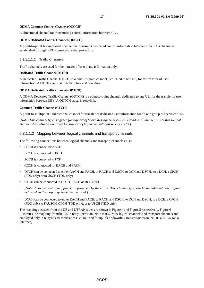
5.3.1.1.2 Mapping between logical channels and transport channels
The following connections between logical channels and transport channels exist:
• SCCH is connected to SCH
• BCCH is connected to BCH
• PCCH is connected to PCH
• CCCH is connected to RACH and FACH
• DTCH can be connected to either RACH and FACH, to RACH and DSCH, to DCH and DSCH, to a DCH, a CPCH (FDD only) or to USCH (TDD only)
• CTCH can be connected to DSCH, FACH or BCH (ffs.)
[Note: Above potential mappings are proposed by the editor. This channel type will be included into the Figures below when the mappings have been agreed.]
• DCCH can be connected to either RACH and FACH, to RACH and DSCH, to DCH and DSCH, to a DCH, a CPCH (FDD only) to FAUSCH, CPCH (FDD only), or to USCH (TDD only).
The mappings as seen from the UE and UTRAN sides are shown in Figure 4 and Figure 5 respectively. Figure 6 illustrates the mapping from the UE in relay operation. Note that ODMA logical channels and transport channels are employed only in relaylink transmissions (i.e. not used for uplink or downlink transmissions on the UE-UTRAN radio interface).

3GPP
18 TS 25.301 V3.1.0 (1999-06)
BCH PCH DSCHFACHRACH DCH
BCCH-SAP
SCH(TDD only)
DCCH-SAP
CCCH-SAP
PCCH-SAP
SCCH-SAP
DTCH-SAP
TransportChannels
MAC SAPs
FAUSCH USCH(TDD only)
CPCH(FDD only)
Figure 4: Logical channels mapped onto transport channels, seen from the UE side
BCH PCH DSCHFACHRACH DCH
BCCH-SAP
DCCH-SAP
CCCH-SAP
PCCH-SAP
SCCH-SAP
DTCH-SAP
TransportChannels
MAC SAPs
FAUSCHSCH(TDD only)
USCH(TDD only)
CPCH(FDD only)
Figure 5: Logical channels mapped onto transport channels, seen from the UTRAN side
ORACH ODCH
ODCCH-SAP
OCCCH-SAP
ODTCH-SAP
TransportChannels
MAC SAPs
Figure 6: Logical channels mapped onto transport channels, seen from the UE side (relay only)

3GPP
19 TS 25.301 V3.1.0 (1999-06)
5.3.1.2 MAC functions
The functions of MAC include:
• Mapping between logical channels and transport channels. The MAC is responsible for mapping of logical channel(s) onto the appropriate transport channel(s).
• Selection of appropriate Transport Format for each Transport Channel depending on instantaneous source rate. Given the Transport Format Combination Set assigned by RRC, MAC selects the appropriate transport format within an assigned transport format set for each active transport channel depending on source rate. The control of transport formats ensures efficient use of transport channels.
• Priority handling between data flows of one UE. When selecting between the Transport Format Combinations in the given Transport Format Combination Set, priorities of the data flows to be mapped onto the corresponding Transport Channels can be taken into account. Priorities are e.g. given by attributes of radio access bearer services and RLC buffer status. The priority handling is achieved by selecting a Transport Format Combination for which high priority data is mapped onto L1 with a “high bit rate” Transport Format, at the same time letting lower priority data be mapped with a “low bit rate” (could be zero bit rate) Transport Format. Transport format selection may also take into account transmit power indication from Layer 1.
• Priority handling between UEs by means of dynamic scheduling. In order to utilize the spectrum resources efficiently for bursty transfer, a dynamic scheduling function may be applied. Priority handling on common and shared transport channels is realized by MAC. Note that for dedicated transport channels, the equivalent of the dynamic scheduling function is implicitly included as part of the reconfiguration function of the RRC sublayer. For TDD it is regarded as further study item.
Note that in the TDD mode the data to be transported are represented in terms of sets of resource units.
• Scheduling of broadcast, paging and notification messages. This function provides mechanisms for efficient transfer of broadcast, paging and notification messages by means of appropriate scheduling and repetition of the messages.
• Identification of UEs on common transport channels. When a particular UE is addressed on a common downlink channel, or when a UE is using the RACH, there is a need for inband identification of the UE. Since the MAC layer handles the access to, and multiplexing onto, the transport channels, the identification functionality is naturally also placed in MAC.
• Multiplexing/demultiplexing of higher layer PDUs into/from transport blocks delivered to/from the physical layer on common transport channels. MAC should support service multiplexing for common transport channels, since the physical layer does not support multiplexing of these channels.
• Multiplexing/demultiplexing of higher layer PDUs into/from transport block sets delivered to/from the physical layer on dedicated transport channels. The MAC allows service multiplexing for dedicated transport channels. This function can be utilized when several upper layer services (e.g. RLC instances) can be mapped efficiently on the same transport channel. In this case the identification of multiplexing is contained in the MAC protocol control information.
• Traffic volume monitoring. Measurement of traffic volume on logical channels and reporting to RRC. Based on the reported traffic volume information, RRC performs transport channel switching decisions.
• Routing of higher layer signalling . This function performs the mapping of higher layer signalling messages to the appropriate transport channel. This function is required in TDD mode, where resource allocation is performed by the MAC autonomously.
• Maintenance of a MAC signalling connection between peer MAC entities. This function supports unacknowledged transfer of MAC-internal messages between peer MAC entities. A MAC signalling connection is required in the TDD mode.
• Monitoring the links of the assigned resources . This function provides means for monitoring link quality in TDD mode (used by MAC for fast DCA).
• Dynamic Transport Channel type switching. Execution of the switching between common and dedicated transport channels based on a switching decision derived by RRC.
• Ciphering. This function prevents unauthorized acquisition of data. Ciphering is performed in the MAC layer for transparent RLC mode.
3GPP
20 TS 25.301 V3.1.0 (1999-06)
The following potential functions are regarded as further study items:
• Processing of messages received at common control channels. This function is applied in TDD mode to support a data transfer on common control channels to support MAC operation (needed for fast DCA details are ffs.).
• Successive Transmission on RACH. This function is needed when the mobile station continues to transmit the succeeding (second or more) radio frames because the message length is longer than a radio frame.
[Note: This function requires further clarification. Contributions are invited.]
• Access Service Class selection for RACH transmission. The RACH resources (i.e. access slots and preamble signatures) may be divided between different Access Service Classes in order to provide different priorities of RACH usage. This function selects, based upon the type of data to be transmitted, the RACH parameters in accordance with the Service Access Class assignment.
[Note: This function may support admission control. Its impact on BCCH capacity and its effects on RACH interference, retransmission and back-off time remains ffs.]
5.3.2 RLC Services and Functions
This section provides an overview on services and functions provided by the RLC sublayer. A detailed description of the RLC protocol is given in 3GPP TS 25.322 [8].
5.3.2.1 Services provided to the upper layer
• RLC connection establishment/release. This service performs establishment/release of RLC connections.
• Transparent data transfer. This service transmits higher layer PDUs without adding any protocol information, possibly including segmentation/reassembly functionality.
• Unacknowledged data transfer. This service transmits higher layer PDUs without guaranteeing delivery to the peer entity. The unacknowledged data transfer mode has the following characteristics:
• Detection of erroneous data: The RLC sublayer shall deliver only those SDUs to the receiving higher layer that are free of transmission errors by using the sequence-number check function.
• Unique delivery: The RLC sublayer shall deliver each SDU only once to the receiving upper layer using duplication detection function.
• Immediate delivery: The receiving RLC sublayer entity shall deliver a SDU to the higher layer receiving entity as soon as it arrives at the receiver.
• Acknowledged data transfer. This service transmits higher layer PDUs and guarantees delivery to the peer entity. In case RLC is unable to deliver the data correctly, the user of RLC at the transmitting side is notified. For this service, both in-sequence and out-of-sequence delivery are supported. In many cases a higher layer protocol can restore the order of its PDUs. As long as the out-of-sequence properties of the lower layer are known and controlled (i.e. the higher layer protocol will not immediately request retransmission of a missing PDU) allowing out-of-sequence delivery can save memory space in the receiving RLC. The acknowledged data transfer mode has the following characteristics:
• Error-free delivery: Error-free delivery is ensured by means of retransmission. The receiving RLC entity delivers only error-free SDUs to the higher layer.
• Unique delivery: The RLC sublayer shall deliver each SDU only once to the receiving upper layer using duplication detection function.
• In-sequence delivery: RLC sublayer shall provide support for in-order delivery of SDUs, i.e., RLC sublayer should deliver SDUs to the receiving higher layer entity in the same order as the transmitting higher layer entity submits them to the RLC sublayer.
• Out-of-sequence delivery: Alternatively to in-sequence delivery, it shall also be possible to allow that the receiving RLC entity delivers SDUs to higher layer in different order than submitted to RLC sublayer at the transmitting side.
• QoS setting. The retransmission protocol shall be configurable by layer 3 to provide different levels of QoS. This can be controlled.

3GPP
21 TS 25.301 V3.1.0 (1999-06)
• Notification of unrecoverabl e errors . RLC notifies the upper layer of errors which cannot be resolved by RLC itself by normal exception handling procedures. e.g. by adjusting the maximum number of retransmissions according to delay requirements.
The following service is regarded as further study item:
• Multicast delivery of higher layer messages. It is left for further study whether or not special functionality on RLC is needed for support of acknowledged transfer of user data to a specified group of UEs.
[Note: Contributions on this issue are invited.]
The length of a higher layer PDU (RLC SDU) can be variable up to the maximum length specified for each data transfer service [ffs.]. There is only a single RLC connection per Radio Access Bearer.
5.3.2.2 RLC Functions
• Connection Control. This function performs establishment, release, and maintenance of a RLC connection.
• Segmentation and reassembly. This function performs segmentation/reassembly of variable-length higher layer PDUs into/from smaller RLC Payload Units (PUs). One RLC PDU carries one PU or, in case header compression is applied several RLC PUs. The size oft the smallest retransmission unit shall be determined by the smallest possible bit rate. The RLC PDU size is adjustable to the actual set of transport formats.
• Header compression. The feature to include several Payload Units into one RLC PDU is referred to as RLC header compression. RLC header compression can be applied for acknowledged data transfer service. Its applicability shall be negotiable between network and UE. Application of RLC header compression is optional for the network but it shall be supported by the UE mandatory.
• Concatenation. If the contents of an RLC SDU does not fill an integer number of RLC PUs, the first segment of the next RLC SDU may be put into the RLC PU in concatenation with the last segment of the previous RLC SDU.
• Padding. When concatenation is not applicable and the remaining data to be transmitted does not fill an entire RLC PDU of given size, the remainder of the data field shall be filled with padding bits.
• Transfer of user data. This function is used for conveyance of data between users of RLC services. RLC supports acknowledged, unacknowledged and transparent data transfer. Transfer of user data is controlled by QoS setting.
• Error correction. This function provides error correction by retransmission (e.g. Selective Repeat, Go Back N, or a Stop-and-Wait ARQ) in acknowledged data transfer mode.
• In-sequence delivery of higher layer PDUs . This function preserves the order of higher layer PDUs that were submitted for transfer by RLC using the acknowledged data transfer service. If this function is not used, out-of-sequence delivery is provided.
• Duplicate Detection. This function detects duplicated received RLC PDUs and ensures that the resultant higher Layer PDU is delivered only once to the upper layer.
• Flow control. This function allows an RLC receiver to control the rate at which the peer RLC transmitting entity may send information.
• Sequence number check (Unacknowledged data transfer mode). This function guarantees the integrity of reassembled PDUs and provides a mechanism for the detection of corrupted RLC SDUs through checking sequence number in RLC PDUs when they are reassembled into a RLC SDU. A corrupted RLC SDU will be discarded.
• Protocol error detection and recovery. This function detects and recovers from errors in the operation of the RLC protocol.
• Ciphering. This function prevents unauthorized acquisition of data. Ciphering is performed in RLC layer for non-transparent RLC mode.
The following potential function(s) are regarded as further study items:
• Suspend/resume function. Suspension and resumption of data transfer as in e.g. LAPDm (cf. GSM 04.05).
• Quick repeat (C plane only). This function provides mechanisms to transmit unacknowledged mode data PDUs several times.
[Note: Whether quick repeat function is performed by layer 3 or by RLC sublayer is FFS..]

3GPP
22 TS 25.301 V3.1.0 (1999-06)
5.3.3 Data flows through Layer 2
Data flows through layer 2 are characterized by the applied data transfer modes on RLC (acknowledged, unacknowledged and transparent transmission) in combination with the data transfer type on MAC, i.e. whether or not a MAC header is required. The case where no MAC header is required is referred to as “transparent” MAC transmission. Acknowledged and unacknowledged RLC transmissions both require a RLC header. In unacknowledged transmission, only one type of unacknowledged data PDU is exchanged between peer RLC entities In acknowledged transmission, both (acknowledged) data PDUs and control PDUs are exc hanged between peer RLC entities.
The resulting different data flow cases are illustrated in Figures 7 - 10. On the level of detail presented here, differences between acknowledged and unacknowledged RLC transmission are not visible. Acknowledged and unacknowledged RLC transmission is shown as one case, referred to as non-transparent RLC.
[Note: The term “transparent transmission” is used here to characterize the case where a protocol, MAC or RLC, does not require any protocol control information (e.g. header). In transparent transmission mode, however, some protocol functions may still be applied. In this case an entity of the respective protocol must be present even when the protocol is transparent. For the RLC protocol the segmentation/reassembly function may be applied. This can be performed without segmentation header when a given higher layer PDU fits into a fixed number of RLC PDUs to be transferred in a given transmission time interval. In this case segmentation/reassembly follows predefined rules known to sending and receiving RLC entities. For instance in the user plane, the segmentation/reassembly function is needed for the case of real-time services using high and possibly variable bit rates. For such services higher layer PDUs shall be segmented into reasonably sized RLC PDUs of fixed length allowing efficient FCS error detection on the physical layer. The higher layer PDU can be reassembled by simply concatenating all RLC PDUs included in a transport block set as implied by the used transport format.]
Figure 7 and Figure 8 illustrate the data flows for transparent RLC with transparent and non-transparent MAC transmission, respectively.
Figure 9 and Figure 10 illustrate the data flows for non-transparent RLC with transparent and non-transparent MAC transmission, respectively.
For acknowledged RLC transmission mode, a single RLC PDU may include more than one segment (referred to as Payload Unit, cf. TS 25.322 [8]) of RLC SDU. This feature, referred to as RLC header compression, is not shown here in the data flow.
A number of MAC PDUs shown in the figures shall comprise a transport block set. Note, however, that in all cases a transport block set must not necessarily match with a RLC SDU. The span of a transport block set can be smaller or larger than a RLC SDU.
Each mapping between a logical channel and a transport channel as defined in Figure 4 and Figure 5 in combination with the respective RLC transmission mode implies a certain data flow which is specified on a general level in the following.

3GPP
23 TS 25.301 V3.1.0 (1999-06)
Higher Layer PDU
L1
MAC SDU
Transport block (MAC PDU)
CRC
MAC SDU
Transport block (MAC PDU)
CRC
…
…
…
RLC PDU RLC PDU…
RLC SDU
HigherLayer
L2 MAC(transparent)
L2 RLC(transparent)
segmentation
reassembly
Figure 7: Data flow for transparent RLC and MAC
L1
L2 MAC
(non-transparent) MAC SDU
Transport block (MAC PDU)
CRC
MAC SDU
Transport block (MAC PDU)
CRC
…
…
MACheader
MACheader
…
L2 RLC(transparent)
Higher Layer PDU
RLC PDU RLC PDU…
RLC SDU
HigherLayer
segmentation
reassembly
Figure 8: Data flow for transparent RLC and non-transparent MAC

3GPP
24 TS 25.301 V3.1.0 (1999-06)
Higher Layer
L1
Higher Layer PDU
RLC SDU
RLCheader
MAC SDU
Transport block (MAC PDU)
CRC
Segmentation &concatenation
reassembly
…
RLCheader…
MAC SDU
Transport block (MAC PDU)
CRC
…
…
L2 MAC(transparent)
L2 RLC(non-transparent)
Higher Layer PDU
RLC SDU
Figure 9: Data flow for non-transparent RLC and transparent MAC
Higher Layer
L1
Higher Layer PDU
RLC SDU
MAC SDU
Transport block (MAC PDU)
CRC
…
RLCheader
RLC
header…
MAC SDU
Transport block (MAC PDU)
CRC
…
…
MACheader
MAC
header
…
L2 MAC(non-transparent)
L2 RLC(non-transparent) Segmentation &
concatenation
reassembly
Higher Layer PDU
RLC SDU
Figure 10: Data flow for non-transparent RLC and MAC
5.3.3.1 Data flow for BCCH mapped to BCH (ffs.)
Regarding the mapping of RRC PDUs into RLC PDUs two alternatives can be considered:
(i) All RRC PDUs transmitted on BCCH have a fixed length and fit into one (or a fixed number) of RLC PDUs (and, equivalently, MAC PDUs, as defined by the transport format). For this type of segmentation no RLC header is needed, i.e. the transparent data transfer mode of RLC is applied.
(ii) RRC PDUs do not fit to the size of a fixed number of RLC PDUs. In this case the unacknowledged RLC transfer mode must be applied, since segmentation/reassembly requires a RLC header for segmentation sequence control.
A MAC header is needed only if multiple BCCH logical channels are mapped onto a BCH.
If the transparent RLC transfer mode is applied (above option (i)), depending on whether the MAC header is needed or not, either the data flow Figure 7 or Figure 8 is applicable. If the unacknowledged RLC transfer mode is applied (above

3GPP
25 TS 25.301 V3.1.0 (1999-06)
option (ii)), depending on whether the MAC header is needed or not, either the data flow Figure 9 or Figure 10 is applicable.
[Note: It is expected that some of the above mentioned options can be removed when details of the BCCH have been specified.]
5.3.3.2 Data flow for PCCH mapped to PCH (ffs.)
Same data flow is applicable as for BCCH mapped to BCH. A MAC header is needed only if multiple PCCH logical channels are mapped onto a single PCH.
5.3.3.3 Data flow for SCCH mapped to SCH (ffs.)
Same data flow is applicable as for BCCH mapped to BCH. Applied in TDD mode only. A MAC header is not needed. The data flow shown in Figure 7 or Figure 9 applies, depending on applied RLC transmission mode.
5.3.3.4 Data flow for CCCH mapped to FACH/RACH (ffs)
For CCCH, transparent or unacknowledged transmission mode on RLC is employed. A MAC header may be used for logical channel identification (CCCH, DCCH, DTCH). When no MAC header is used, CCCH must be the only channel mapped to RACH/FACH. If the transparent RLC transfer mode is applied, depending on whether the MAC header is needed or not, either the data flow Figure 7 or Figure 8 is applicable. If the unacknowledged RLC transfer mode is applied, depending on whether the MAC header is needed or not, either the data flow Figure 9 or Figure 10 is applicable.
[Note: It might be possible that some of the above mentioned options can be removed when all messages carried on CCCH have been specified in detail.]
5.3.3.5 Data flow for DCCH mapped to FACH/RACH
For DCCH, both unacknowledged and acknowledged transmission mode on RLC is employed. A MAC header is mandatory for FACH/RACH carrying DCCH. The data flow shown in Figure 10 is applicable.
5.3.3.6 Data flow for DCCH mapped to DSCH
For DCCH, both unacknowledged and acknowledged transmission mode on RLC is employed. Whether or not a MAC header is needed for UE identification when DCCH is mapped to a DSCH is ffs., i.e. either the data flow in Figure 9 or Figure 10 is applicable.
5.3.3.7 Data flow for DCCH mapped to CPCH
For DCCH mapped to CPCH, unacknowledged or acknowledged transmission modes on RLC are employed. The MAC header is needed for logical channel service multiplexing. Figure 10 is the applicable data flow to this case.
5.3.3.8 Data flow for DTCH (non-transparent RLC) mapped to FACH/RACH
Mapping to FACH/RACH implies a DTCH with acknowledged (possibly also unacknowledged, ffs.) transmission on RLC. A MAC header is mandatory for FACH/RACH when carrying DTCH. The data flow shown in Figure 10 is applicable.
5.3.3.9 Data flow for DTCH (non-transparent RLC) mapped to DSCH
Mapping to DSCH implies a DTCH with acknowledged (possibly also unacknowledged, ffs.) transmission on RLC. Whether or not a MAC header is needed for UE identification when DTCH is mapped to a DSCH is ffs., i.e. either the data flow in Figure 9 or Figure 10 is applicable.
5.3.3.10 Data flow for DTCH (transparent RLC) mapped to DCH
Continuous DTCH data stream is segmented into transport blocks on RLC and mapped on a DCH transport channel on MAC. The transport block size is naturally implied by the data rate. Both RLC and MAC sublayers are transparent, i.e. no protocol control information is added, when no multiplexing of DTCH on MAC is applied. The data flow shown in Figure 7 is applicable. If multiplexing on MAC is performed, a MAC header is needed, and Figure 8 applies.

3GPP
26 TS 25.301 V3.1.0 (1999-06)
5.3.3.11 Data flow for DTCH (non-transparent RLC) mapped to DCH
In this case acknowledged or unacknowledged transmission on RLC is applied. A MAC header is needed only if multiple DTCH logical channels are multiplexed in MAC before mapping to a DCH, i.e. either the data flow in Figure 9 or Figure 10 is applicable.
5.3.3.12 Data flow for DTCH (non-transparent RLC) mapped to CPCH.
This case requires both non-transparent RLC and MAC operations. The data flow shown in Figure 10 is applicable.
5.3.3.13 Data flow for DCCH mapped to DCH
In this case non-transparent transmission mode on RLC is applied. A MAC header is needed only if DCCH and DTCH logical channels are multiplexed in MAC before mapping to a DCH, i.e. either the data flow in Figure 9 or Figure 10 is applicable.
5.4 Layer 3 - RRC Services and Functions This sections provides an overview on services and functions provided by the RRC layer. A detailed description of the RRC protocol is given in 3GPP TS 25.331 [9]. Examples of structured procedures involving RRC in Idle Mode and Connected Mode are described in 3GPP TS 25.303 [5] and 3GPP TS 25.304 [6], respectively.
5.4.1 RRC services
5.4.1.1 General Control
The GC SAP provides an information broadcast service. This service broadcasts information to all UEs in a certain geographical area. The basic requirements from such service are:
• It should be possible to broadcast non-access stratum information in a certain geographical area.
• The information is transferred on an unacknowledged mode link. Unacknowledged mode means that the delivery of the broadcast information can not be guaranteed (typically no retransmission scheme is used). It seems reasonable to use an unacknowledged mode link since the information is broadcast to a lot of UEs and since broadcast information often is repeated periodically.
• It should be possible to do repeated transmissions of the broadcast information (how it is repeated is controlled by the non-access stratum).
• The point where the UE received the broadcast information should be included, when the access stratum delivers broadcast information to the non-access stratum.
5.4.1.2 Notification
The Nt SAP provides paging and notification broadcast services. The paging service sends information to a specific UE(s). The information is broadcast in a certain geographical area but addressed to a specific UE(s). The basic requirements from such service are:
• It should be possible to broadcast paging information to a number of UEs in a certain geographical area.
• The information is transferred on an unacknowledged mode link. It is assumed that the protocol entities in non-access stratum handle any kind of retransmission of paging information.
The notification broadcast service broadcasts information to all UEs in a certain geographical. The basic requirements from this service are typically the same as for the information broadcast service of the GC SAP:
• It should be possible to broadcast notification information in a certain geographical area.
• The information is transferred on an unacknowledged mode link.
3GPP
27 TS 25.301 V3.1.0 (1999-06)
5.4.1.3 Dedicated Control
The DC SAP provides services for establishment/release of a connection and transfer of messages using this connection. It should also be possible to transfer a message during the establishment phase. The basic requirements from the establishment/release services are:
• It should be possible to establish connections (both point and group connections).
• It should be possible to transfer an initial message during the connection establishment phase. This message transfer has the same requirements as the information transfer service.
• It should be possible to release connections.
The information transfer service sends a message using the earlier established connection. According to [1] it is possible to specify the quality of service requirements for each message. A finite number of quality of service classes will be specified in [1], but currently no class has been specified. In order to get an idea of the basic requirements, the CC and MM protocols in GSM are used as a reference. A GSM based core network is chosen since it is one main option for UMTS. Considering the existing GSM specification of CC and MM the basic requirements from the information transfer service are (these are some the services provided by RR and the data link layer in GSM):
• Acknowledged mode link for transfer of messages This acknowledged mode link guarantees that the CC and MM messages are transferred to the corresponding side. Acknowledged mode means that the delivery of upper layer information can be guaranteed (some kind of retransmission scheme is used). A connection between two DC SAPs using an acknowledged mode link is called signalling connection. This link should also guarantee that no messages are lost or duplicated during handover.
• Preserved message order The order of the transferred messages is preserved.
• Priority handling If SMS messages should be transported through the control plane it should be possible to give higher priority to signalling messages.
The CC and MM protocols also expect other services, which can not be supported by the current primitives of the DC SAP, e.g. indication of radio link failure.
5.4.2 RRC functions
The Radio Resource Control (RRC) layer handles the control plane signalling of Layer 3 between the UEs and UTRAN. The RRC performs the following functions:
• Broadcast of information provided by the non-access stratum (Core Network). The RRC layer performs system information broadcasting from the network to all UEs. The system information is normally repeated on a regular basis. This function supports broadcast of higher layer (above RRC) information. This information may be cell specific or not. As an example RRC may broadcast Core Network location service area information related to some specific cells.
• Broadcast of information related to the access stratum. The RRC layer performs system information broadcasting from the network to all Ues This function supports broadcast of typically cell-specific information.
• Broadcast of ODMA relay node neighbour information. The RRC layer performs probe information broadcasting to allow ODMA routeing information to be collected.
• Establishment, maintenance and release of an RRC connection between the UE and UTRAN. The establishment of an RRC connection is initiated by a request from higher layers at the UE side to establish the first Signalling Connection for the UE. The establishment of an RRC connection includes an optional cell re-selection, an admission control, and a layer 2 signalling link establishment. The release of an RRC connection can be initiated by a request from higher layers to release the last Signalling Connection for the UE or by the RRC layer itself in case of RRC connection failure. The RRC layer detects loss of RRC connection and releases resources assigned for the RRC connection in case of connection failure.
• Collating ODMA neighbour list and gradient information. The ODMA relay node neighbour lists and their respective gradient information will be maintaining by the RRC.
• Maintenance of number of ODMA relay node neighbours. The RRC will adjust the broadcast powers used for probing messages to maintain the desired number of neighbours.
3GPP
28 TS 25.301 V3.1.0 (1999-06)
• Establishment, maintenance and release of a route between ODMA relay nodes. The establishment of an ODMA route and RRC connection based upon the routeing algorithm.
• Interworking between the Gateway ODMA relay node and the UTRAN. The RRC layer will control the interworking with the standard TDD or FDD communication link between the Gateway ODMA relay node and the UTRAN.
• Establishment, reconfiguration and release of Radio Access Bearers. The RRC layer can, on request from higher layers, perform the establishment, reconfiguration and release of radio access bearers in the user plane. A number of radio access bearers can be established to an UE at the same time. At establishment and reconfiguration, the RRC layer performs admission control and selects parameters describing the radio access bearer processing in layer 2 and layer 1, based on information from higher layers.
• Assignment, reconfiguration and release of radio resources for the RRC connection. The RRC layer handles the assignment of radio resources (e.g. codes, CPCH channels) needed for the RRC connection including needs from both the control and user plane. The RRC layer may reconfigure radio resources during an established RRC connection. This function includes coordination of the radio resource allocation between multiple radio bearers related to the same RRC connection. RRC controls the radio resources in the uplink and downlink such that UE and UTRAN can communicate using unbalanced radio resources (asymmetric uplink and downlink). RRC signals to the UE to indicate resource allocations for purposes of handover to GSM or other radio systems.
• RRC connection mobility functions. The RRC layer performs evaluation, decision and execution related to RRC connection mobility during an established RRC connection, such as handover, preparation of handover to GSM or other systems, cell re-selection and cell/paging area update procedures, based on e.g. measurements done by the UE.
• Paging/notification. The RRC layer can broadcast paging information from the network to selected UEs. Paging and notification can be requested by higher layers on the network side. The RRC layer can also initiate paging during an established RRC connection.
• Routing of higher layer PDUs. This function performs at the UE side routing of higher layer PDUs to the correct higher layer entity, at the UTRAN side to the correct RANAP entity.
• Control of requested QoS. This function shall ensure that the QoS requested for the radio access bearers can be met. This includes the allocation of a sufficient number of radio resources. The exact requirements on RRC to support this function are ffs.
• UE measurement reporting and control of the reporting. The measurements performed by the UE are controlled by the RRC layer, in terms of what to measure, when to measure and how to report, including both UMTS air interface and other systems. The RRC layer also performs the reporting of the measurements from the UE to the network.
• Outer loop power control. The RRC layer controls setting of the target of the closed loop power control.
• Control of ciphering. The RRC layer provides procedures for setting of ciphering (on/off) between the UE and UTRAN.
• Slow DCA. Allocation of preferred radio resources based on long-term decision criteria. It is applicable only in TDD mode.
• Contention resolution. The RRC handles reallocations and releases of radio resources in case of collisions indicated by lower layers in TDD mode. Applicability of contention resolution in FDD mode is ffs.
• Arbitration of radio resources on uplink DCH. This function controls the allocation of radio resources on uplink DCH on a fast basis, using a broadcast channel to send control information to all involved users. [Note: This function is implemented in the CRNC. Details are ffs.]
• Initial cell selection and re-selection in idle mode. Selection of the most suitable cell based on idle mode measurements and cell selection criteria.
The following functions are regarded as further study items:
• Arbitration of the radio resource allocation between the cells. This function shall ensure optimal performance of the overall UTRAN capacity.
[Note: Some clarification should be provided what exact requirements this function implies on the RRC protocol, beyond general radio resource optimization.]
• Congestion control. Further study item.

3GPP
29 TS 25.301 V3.1.0 (1999-06)
5.5 Interactions between RRC and lower layers in the C plane The RRC protocol controls and signals the allocation of radio resources to the UE. RRC allows MAC to arbitrate between users and radio access bearers within the radio resource allocation. The RRC uses the measurements done by the lower layers to determine which radio resources that are available. Therefore it is a need for a measurement report from the UE RRC to the UTRAN RRC. Figure 11 illustrates the principle. The local control and local measurements reporting is handled through the control SAPs between RRC and the lower layers.
5.6 Protocol termination This section specifies in which node of the UTRAN the radio interface protocols are terminated, i.e. where within UTRAN the respective protocol services are accessible.
5.6.1 Protocol termination for DCH
Figure 12 and Figure 13 show the protocol termination for DCH for the control and user planes, respectively. The part of physical layer terminating in the Serving RNC is the topmost macro-diversity combining and splitting function for the FDD mode. If no macrodiversity applies, the physical layer is terminated in Node B.
R R C R R C
R L C R L C
Radio ResourceAssignment[Code, Frequency,TS, TF Set, Mapping,etc.]
Measurement Report
RLC retransmissioncontrol
L 1 L 1
U T R A N U E
Con
trol
Mea
sure
men
ts
Con
trol
Mea
sure
men
ts
Con
trol
Mea
sure
men
ts
Con
trol
Mea
sure
men
ts
M A C M A C
MAC signalling(TDD mode)
Con
trol
Con
trol
Figure 11: Interactions between RRC and lower layers

3GPP
30 TS 25.301 V3.1.0 (1999-06)
UE NodeB
RRC
RLC
PHYPHY
SRNC
RRC
RLC
PHY
MAC MAC
Figure 12: Protocol Termination for DCH, control plane
UE NodeB
RLC
PHYPHY
SRNC
RLC
PHY
MAC MAC
Figure 13: Protocol Termination for DCH, user plane
5.6.2 Protocol termination for RACH/FACH
Figure 14 and Figure 15 show the protocol termination for RACH/FACH for the control and user planes, respectively. Control plane termination refers to the case where RACH/FACH carry dedicated or common control information (i.e. CCCH or DCCH). User plane termination refers to the case where RACH/FACH carry user data (DTCH) (two alternatives cases, referred to as case B and C, are described in the Annex).
It is assumed that macrodiversity/soft handover is not applied for RACH/FACH. Therefore, the physical layer terminates in Node B. For RACH/FACH carrying DCCH, MAC is split between Controlling and Serving RNC. RLC, and in the C plane also RRC terminate in the Serving RNC. Since Iur can support common channel data streams, the users of that common channel can depend on different SRNCs. However, they depend on the same Controlling RNC. Therefore, for a given user, the Controlling RNC and the Serving RNC can be separate RNCs.
For RACH/FACH carrying CCCH, MAC, RLC and RRC are terminated in the RNC.
[Note: It is currently an open issue whether or not there are CCCH messages that need to be routed between Controlling and Serving RNC over Iur. If it is only the initial access message that is defined for CCCH, C-RNC and S-RNC are always identical and no routing would be needed. If messages such as “URA update”, “Cell update” and “RRC connection re-establishment” would be signalled on CCCH, routing of these messages on RRC level would need to be performed ]

3GPP
31 TS 25.301 V3.1.0 (1999-06)
DCCH:
UE Node B
PHY PHY
ControllingRNC
SRNC
MAC
RRC
RLC
RRC
RLC
MACMAC
UE Node B
PHY PHY
RNC
MACMAC
RRC
RLC
RRC
RLC
CCCH:
Figure 14: Protocol Termination for RACH/FACH, control plane
UE Node B
PHY PHY
ControllingRNC
SRNC
MAC
RLC RLC
MACMAC
Figure 15: Protocol Termination for RACH/FACH, user plane
5.6.3 Protocol termination for FAUSCH
Protocol termination for the FAUSCH is the same as for the RACH in the control plane (see Figure 14), since FAUSCH is for control purposes only.
3GPP
32 TS 25.301 V3.1.0 (1999-06)
5.6.4 Protocol termination for CPCH
The protocol termination for CPCH is identical to the termination for RACH. Figure 14 (for DCCH) presents the control plane protocol termination. Figure 15 presents the user plane protocol termination.
5.6.5 Protocol termination for DSCH
5.6.5.1 DSCH definition
The DSCH is a resource that exists in downlink only. It has only impact on the physical and transport channel levels, so there is no definition of shared channel in the logical channels provided by MAC.
The DSCH is a transport channel shared dynamically between several UEs. The DSCH is mapped to one or several physical channels such that a specified part of the downlink code tree is employed. For the DSCH no macrodiversity is applied, i.e. a specific DSCH is transmitted in a single cell only.
The following two DSCH cases are presently considered, in the following denoted as cases A and B:
Case A: The DSCH is defined is an extension to DCH transmission. DSCH related resource allocation is signalled utilizing the transport format indication field (TFI) that will be mapped to the TFCI of the associated DCH.
Case B: The DSCH is defined as a shared downlink channel for which resource allocation, including UE identification, is signalled on another common downlink channel, referred to as DSCH Control Channel.
[Note: It is considered ffs. whether the DSCH Control Channel requires a new type of transport channel or whether a specific FACH transport channel can be used for this purpose. It is assumed that the DSCH control channel is supported on the PSCCCH (Physical Shared Common Control Channel) if it carries TPC information. It needs to be confirmed by TSG RAN WG1 that this channel will be specified.]
Note: For case B it is assumed that DSCH and DSCH Control Channel employ individual channelization codes each. Time multiplexing of user data (DSCH) and control information (DSCH Control Channel) is not considered.
Note also that a third case of DSCH definition, where the DSCH was defined as a stand-alone channel providing in-band UE identification is not considered any more. This case has been identified as being equivalent to a FACH and is as such already included in the radio interface specification.
Interleaving for the DSCH may be applied over a multiplicity of radio frames. Nevertheless, here the basic case is considered where the interleaving is rectangular for a given MAC PDU, and equal to one radio frame (10 ms). The framing is synchronised on the SCH.
In every radio frame, one or several codes can be used in the downlink. Therefore, the DSCH supports code multiplexing. MAC multiplexing shall not be applied within a radio frame, i.e. the whole radio frame for one code is assigned to a single UE. However, MAC multiplexing is allowed on a frame by frame basis, i.e. one code may be allocated to different UEs at each frame.
Transport blocks on the DSCH may be of constant size, so that the Transport Block Set may be derived from the code allocated to each UE on the DSCH.
5.6.5.2 Resource allocation and UE identification on DSCH
The principles of capacity allocation and UE identification on the DSCH are described in more detail below.
[Note: The two resource allocation methods of the cases A and B might be used simultaneously for one DSCH, i.e. some UEs may use an associated DSCH Control Channel and some UEs may use an associated DCH for resource allocation while transmitting data on the same DSCH. This option is ffs.]
5.6.5.2.1 Case A (UE requires a downlink TFCI on a DPCCH)
The TFCI of the dedicated physical channel may carry the information that a given code of the DSCH must be listened to by the UE. Fast power control can be applied per code based on the dedicated physical control channel, DPCCH.
Alternatively, a UE may be requested on the DCH to listen to a DSCH for a given period of time, and to decode the data so that the address of the destination UE can be decoded. This does not require more TFCI values because signalling is done in layers 2 and 3.

3GPP
33 TS 25.301 V3.1.0 (1999-06)
5.6.5.2.2 Case B (UE requires a downlink DSCH Control Channel)
The information which DSCH code to listen to and when is sent on an additional downlink channel to the UE (essentially a broadcast channel). This channel, is referred to as DSCH Control Channel. It is code multiplexed on the downlink and should convey the following information, which is modified every radio frame:
• Layer 1 information
• TPC bits for each UE which would have an uplink DCH without downlink DCH. The location of TPC bits on the PSCCCH of each cell is allocated to each UE when a RAB is mapped onto a DSCH.
• Channelisation code allocated to each UE indicated relatively to the DSCH code entry point
• Layer 2 information
• Identity of the UEs who should receive information on the DSCH. The UE ID is allocated when a RAB is mapped onto a DSCH. Which UE ID is used to identify UE on the DSCH of each cell is ffs.
This concept allows to perform power control on the DSCH, whereas the DSCH Control Channel would be less efficient in terms of power control efficiency (need to power control on the farthest UE).
5.6.5.3 Model of DSCH in UTRAN
Figure 16 captures the working assumption on the Downlink Shared Channel (DSCH). The two RLCs point to logical channel (DTCH) specific RLC-entities of specific users while MAC refers to the provision of MAC sublayer functions for all users.
The MAC sublayer of a DSCH is split between the Controlling RNC and SRNC. For a given user, the RLC sublayer is terminated in its SRNC. Since Iur can support DSCH data streams, the users on that DSCH can depend on different SRNCs. For a given user, the Controlling RNC and the Serving RNC can be separate RNCs. The MAC in the network takes care of mapping downlink data either to a common channel (FACH, not shown in this figure), DCH or the DSCH.
Figure 16 also includes the DSCH Control Channel, needed for case B of DSCH definition only. See 3GPP TS 25.321 [8] for details on MAC architecture. In this example, the resource allocation on the DSCH is signalled on the DSCH control channel for UE 1 and on the associated DCH for UE 2.

3GPP
34 TS 25.301 V3.1.0 (1999-06)
UE2
DCH
MAC
RLC2
SRNC 1 SRNC 2
DSCH
Signallingfor UE 2
Data forUE 1&2
UE1
SRNCs
RLC1
Controlling RNC
Node B
Signallingfor UE 1
Iur or local
DSCH Cntrl.Channel
MAC-d1 MAC-d2
UE
Uu
MAC-sh
Figure 16: Model of downlink shared channel (DSCH) in UTRAN
5.6.5.4 Protocol termination
The protocol termination points for DSCH in control and user planes are presented in Figure 17 and Figure 18, respectively.
UE Node B
RRC
RLC
PHY PHY
MAC
ControllingRNC
SRNC
RRC
RLC
MAC
MAC MAC
Figure 17: Protocol termination points for DSCH, control plane.
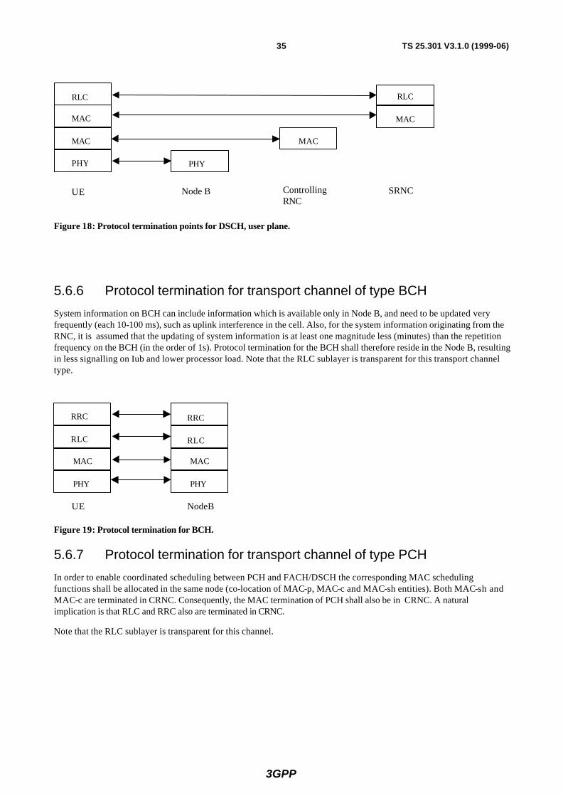
3GPP
35 TS 25.301 V3.1.0 (1999-06)
UE Node B
RLC
PHY PHY
MAC
ControllingRNC
SRNC
RLC
MAC
MAC MAC
Figure 18: Protocol termination points for DSCH, user plane.
5.6.6 Protocol termination for transport channel of type BCH
System information on BCH can include information which is available only in Node B, and need to be updated very frequently (each 10-100 ms), such as uplink interference in the cell. Also, for the system information originating from the RNC, it is assumed that the updating of system information is at least one magnitude less (minutes) than the repetition frequency on the BCH (in the order of 1s). Protocol termination for the BCH shall therefore reside in the Node B, resulting in less signalling on Iub and lower processor load. Note that the RLC sublayer is transparent for this transport channel type.
UE NodeB
RLC
MAC
PHY
RLC
MAC
PHY
RRC RRC
Figure 19: Protocol termination for BCH.
5.6.7 Protocol termination for transport channel of type PCH
In order to enable coordinated scheduling between PCH and FACH/DSCH the corresponding MAC scheduling functions shall be allocated in the same node (co-location of MAC-p, MAC-c and MAC-sh entities). Both MAC-sh and MAC-c are terminated in CRNC. Consequently, the MAC termination of PCH shall also be in CRNC. A natural implication is that RLC and RRC also are terminated in CRNC.
Note that the RLC sublayer is transparent for this channel.

3GPP
36 TS 25.301 V3.1.0 (1999-06)
[Note: Above termination of PCH has been agreed as working assumption. Some WG2 members however requested some more time for further consideration. The above assumption shall be confirmed before or at the next WG2 meeting. The previous solution is kept in the Annex as alternative PCH termination option.]
UE Node B
RRC
PHY PHY
MAC
ControllingRNC
RRC
MAC
RLC RLC
Figure 20: Protocol termination for PCH
5.6.8 Protocol termination for transport channel of type SCH
The SCH transport channel is used in TDD mode only. Protocol termination for SCH is the same as for BCH as shown in Figure 19.
5.6.9 Protocol termination for ODCH
Figure 21 and Figure 22 show the protocol termination for ODCH in the control and user planes, respectively.
Root ODMArelay node
ODMArelay node
GatewayODMA
relay node
ODMArelay node
RRC
RLC
MAC
PHY
RRC
RLC
MAC
PHY
RRC
RLC
MAC
PHY
RRC
RLC
MAC
PHY
RRC
RLC
MAC
PHY
RRC
RLC
MAC
PHY
RRC
RLC
MAC
PHY
RRC
RLC
MAC
PHY
UTRAN
Figure 21: Protocol Termination for the ODCH in the Control Plane
Root ODMArelay node
ODMArelay node
GatewayODMA
relay node
ODMArelay node
RLC
MAC
PHY
RLC
MAC
PHY
RLC
MAC
PHY
RLC
MAC
PHY
RLC
MAC
PHY
RLC
MAC
PHY
RLC
MAC
PHY
RLC
MAC
PHYUTRAN
Figure 22: Protocol Termination for the ODCH in the User Plane
Note: The current mechanisms and procedures carried out by the RLC and the MAC for the DCH will require minor, subtle modifications to enable them to handle the ODCH.

3GPP
37 TS 25.301 V3.1.0 (1999-06)
5.6.10 Protocol termination for ORACH
The protocol termination for ORACH for the control and user planes are illustrated in Figure 23 and Figure 24, respectively. The shown ODMA relay nodes may be either UER, Seed, Root, or Gateway.
ODMArelay node
ODMArelay node
RRC
RLC
MAC
PHY
RRC
RLC
MAC
PHY
Figure 23: Protocol Termination for ORACH control plane
ODMArelay node
ODMArelay node
RLC
MAC
PHY
RLC
MAC
PHY
Figure 24: Protocol Termination for ORACH user plane
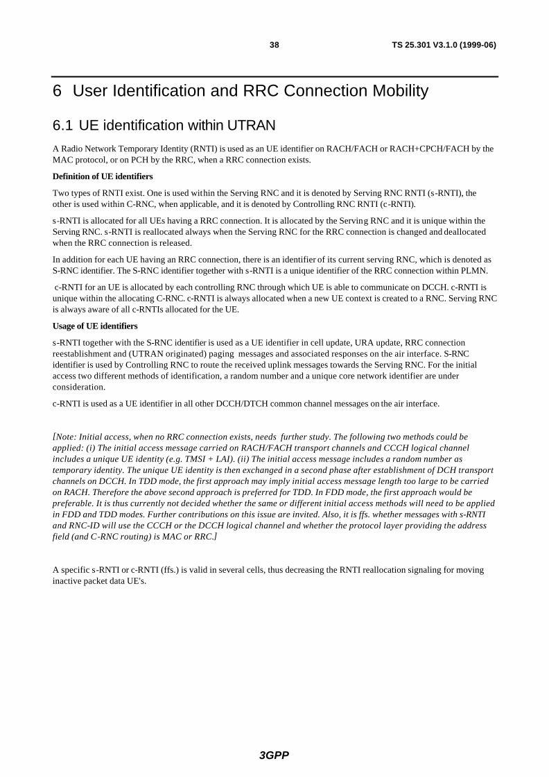
3GPP
38 TS 25.301 V3.1.0 (1999-06)
6 User Identification and RRC Connection Mobility
6.1 UE identification within UTRAN A Radio Network Temporary Identity (RNTI) is used as an UE identifier on RACH/FACH or RACH+CPCH/FACH by the MAC protocol, or on PCH by the RRC, when a RRC connection exists.
Definition of UE identifiers
Two types of RNTI exist. One is used within the Serving RNC and it is denoted by Serving RNC RNTI (s-RNTI), the other is used within C-RNC, when applicable, and it is denoted by Controlling RNC RNTI (c-RNTI).
s-RNTI is allocated for all UEs having a RRC connection. It is allocated by the Serving RNC and it is unique within the Serving RNC. s-RNTI is reallocated always when the Serving RNC for the RRC connection is changed and deallocated when the RRC connection is released.
In addition for each UE having an RRC connection, there is an identifier of its current serving RNC, which is denoted as S-RNC identifier. The S-RNC identifier together with s-RNTI is a unique identifier of the RRC connection within PLMN.
c-RNTI for an UE is allocated by each controlling RNC through which UE is able to communicate on DCCH. c-RNTI is unique within the allocating C-RNC. c-RNTI is always allocated when a new UE context is created to a RNC. Serving RNC is always aware of all c-RNTIs allocated for the UE.
Usage of UE identifiers
s-RNTI together with the S-RNC identifier is used as a UE identifier in cell update, URA update, RRC connection reestablishment and (UTRAN originated) paging messages and associated responses on the air interface. S-RNC identifier is used by Controlling RNC to route the received uplink messages towards the Serving RNC. For the initial access two different methods of identification, a random number and a unique core network identifier are under consideration.
c-RNTI is used as a UE identifier in all other DCCH/DTCH common channel messages on the air interface.
[Note: Initial access, when no RRC connection exists, needs further study. The following two methods could be applied: (i) The initial access message carried on RACH/FACH transport channels and CCCH logical channel includes a unique UE identity (e.g. TMSI + LAI). (ii) The initial access message includes a random number as temporary identity. The unique UE identity is then exchanged in a second phase after establishment of DCH transport channels on DCCH. In TDD mode, the first approach may imply initial access message length too large to be carried on RACH. Therefore the above second approach is preferred for TDD. In FDD mode, the first approach would be preferable. It is thus currently not decided whether the same or different initial access methods will need to be applied in FDD and TDD modes. Further contributions on this issue are invited. Also, it is ffs. whether messages with s-RNTI and RNC-ID will use the CCCH or the DCCH logical channel and whether the protocol layer providing the address field (and C-RNC routing) is MAC or RRC.]
A specific s-RNTI or c-RNTI (ffs.) is valid in several cells, thus decreasing the RNTI reallocation signaling for moving inactive packet data UE's.

3GPP
39 TS 25.301 V3.1.0 (1999-06)
6.2 UE connection to UTRAN The different levels of UE connection to UTRAN are listed below:
• No signalling connection exist The UE has no relation to UTRAN, only to CN. For data transfer, a signalling connection has to be established.
• Signalling connection exist There is a RRC connection between UE and UTRAN. The UE position can be known on different levels:
• UTRAN Registration Area (URA) level The UE position is known on UTRAN registration area level. URA is a specified set of cell which can be identified on the BCCH.
• Cell level The UE position is known on cell level. Different channel types can be used for data transfer:
• Common transport channels (RACH, FACH , CPCH, DSCH),
• Dedicated transport channels (DCH); note that FAUSCH can be used to allocate a dedicated channel for data transmission.
7 UE modes Two modes of operation are defined for the UE, idle mode and connected mode [5, 6].
After power on, the UE stays in idle mode until it transmits a request to establish an RRC connection. In idle mode the UE is identified by non-access stratum identities such as IMSI, TMSI and TLLI. In addition, the UTRAN has no own information about the individual idle mode UEs, and can only address e.g. all UEs in a cell or all UEs in a paging group.
The connected mode is entered when the RRC connection is established. The UE is assigned a radio network temporary identity (s-RNTI + S-RNC ID and possibly in addition c-RNTI) to be used as UE identity on common transport channels . [Note: The exact definition of RRC connection needs further refinement.]
The UE leaves the connected mode and returns to idle mode when the RRC connection is released or at RRC connection failure. [Note: whether UE power off causes RRC connection release and/or RRC connection failure is FFS.]
[Note: Other modes than idle mode and connected mode, such as separate mode(s) for the reception of point-to-multipoint information, are FFS.]

3GPP
40 TS 25.301 V3.1.0 (1999-06)
8 Ciphering
8.1 Location of ciphering function in the UTRAN protocol architecture The ciphering function is performed either in the RLC sub-layer or in the MAC sub-layer, according to the following rules :
• If a logical channel is expected to be supported on common transport channel and has to be ciphered, it can not use the transparent mode of RLC (it should use the UM RLC mode instead).
• If a logical channel is using a non-transparent RLC mode (AM or UM), ciphering is performed in the RLC sub-layer.
• If a logical channel is using the transparent RLC mode, ciphering is performed in the MAC sub-layer (MAC-d entity).
According to this model, ciphering is always performed in the SRNC, and the context needed for ciphering (Kc, HFN, etc.) is only known in SRNC.
8.2 Input parameters to the ciphering algorithm
8.2.1 Overview
When ciphering is performed in the RLC sub-layer, it performs the encryption/decryption of the data part of an RLC PDU, based on XOR combining with a mask obtained as an output of the ciphering algorithm.
When ciphering is performed in the MAC sub-layer, it performs the encryption/decryption of a MAC SDU (RLC PDU), based on XOR operation with a mask obtained as an output of the ciphering algorithm.
The generic algorithm and its parameters are described in the following figure. It will be specified by SA3, and requirements are described in TS33.105.
Ciphering algorithm
Kc CSN ID
Direction
Mask
XORUncipheredMAC SDU orRLC PDU (data part)
CipheredMAC SDU orRLC PDU (data part)
Figure 25 : Ciphering algorithm and parameters
8.2.2 Ciphering algorithms parameters
8.2.2.1 Ciphering sequence number
The ciphering sequence number (CSN) shall be at least 32 bits long. It is composed of a ‘long’ sequence number called Hyper Frame Number HFN, and a ‘short’ sequence number, which depends on the ciphering mode, as described below. There is one ciphering sequence per logical channel using AM or UM mode plus one for all logical channels using the transparent mode (and mapped onto DCH).

3GPP
41 TS 25.301 V3.1.0 (1999-06)
The Hyper Frame Number (HFN) is initialised by the UE and signalled to the SRNC before ciphering is started. It is used as initial value for each ciphering sequence, and it is then incremented independently in each ciphering sequence, at each cycle of the ‘short’ sequence number. When a new RAB / logical channel is created during a RRC connection, the highest HFN value currently in use is incremented, and used as initial value for the ciphering sequence of this new logical channel. The highest HFN value used during a RRC connection (by any ciphering sequence) is stored in the USIM, and the UE initialises the new HFN for the next session with a higher number than the stored one. If no HFN value is available in USIM, the UE randomly selects a HFN value.
Depending on the requirements (e.g. how many successive RRC Connections can use the same ciphering key), it may be sufficient to use only the most significant bits of HFN in the re-initialization (and set LSBs implicitly to zero). This may be necessary at least if the HFN value needs to be included in the RRC Connection Request message.
The ‘short’ sequence number is :
• For RLC TM on DCH, the CFN of the UEFN is used and is independently maintained in UE MAC and SRNC MAC-d. The ciphering sequence number is identical to the UEFN.
• For RLC UM and AM modes, the RLC sequence number is used, and is directly available in each RLC PDU at the receiver side (it is not ciphered). The HFN is incremented at each RLC SN cycle.
The figure below presents some examples of the different ciphering sequence numbers, assuming various sizes for the ‘short’ sequence numbers. This proposal permits to exchange a unique HFN and also to use a unique CSN size, which should permit to reduce the implementation complexity of the ciphering function. In this example, the HFN is 25 bits long, and only the 20 MSB are used for the CSN of the RLC AM mode.
HFN (25 bits) CFN (7 bits)MAC-d DCH
HFN (25 bits) RLC SN (7 bits)RLC UM
HFN (20 bits) RLC SN (12 bits)RLC AM
RLC TM
Figure 26 : Example of ciphering sequence number for all possible configurations
8.2.2.2 Ciphering key Kc
Kc is exchanged between the UE and SRNC during the authentication phase. The selection of Kc when a UE is connected with multiple CN is FFS.
8.2.2.3 ID
This parameter indicates the logical channel identity, which shall be unique within a RRC connection. It is used as input parameter of the ciphering algorithm to ensure that the same ciphering mask is not applied to two or more parallel logical channels having the same Kc and same CSN. Each logical channel is ciphered independently.
8.2.2.4 Direction
This parameter indicates the transmission direction (uplink/downlink).

3GPP
42 TS 25.301 V3.1.0 (1999-06)
Annex A (informative): Protocol termination This Annex describes protocol termination cases which have been excluded from the initial UMTS release. These cases are captured here for information. They potentially may be considered for future releases.
A.1 Alternative protocol termination for DCH Figure 27 and Figure 28 show an alternative protocol termination case for DCH for the control and user planes, respectively, referred to as Case B. This case would be applicable when macrodiversity at RNC level is not applied, i.e. especially for DCH in the TDD mode.
UE NodeB
RRC
RLC
PHY PHY
SRNC
RRC
MAC
RLC
MAC
Case B:
Figure 27: Protocol Termination for DCH, control plane
UE NodeB
RLC
PHY PHY
SRNC
MAC
RLC
MAC
Case B:
Figure 28: Protocol Termination for DCH, user plane
A.2 Protocol termination for RACH/FACH Figure 29 and Figure 30 show two alternative protocol termination cases for RACH/FACH for the control and user planes, respectively, referred to as Case B and Case C.
In case B, the physical layer, MAC and RLC terminate in Node B.
In case C, the MAC sublayer is split between Node B, Controlling and Serving RNC. This would be the preferred solution when MAC in Node B shall provide acknowledgements to RACH messages and perform scheduling of FACH transmissions.

3GPP
43 TS 25.301 V3.1.0 (1999-06)
UE NodeB
RRC
RLC
PHY PHY
SRNC
MAC
RRC
RLC
MAC
Case B:
Case C:
UE NodeB
PHY PHY
SRNC
MAC MAC
MAC MAC
RRC
RLC
RRC
RLC
MAC MAC
ControllingRNC
Figure 29: Protocol Termination for RACH/FACH, control plane
UE NodeB
RLC
PHY PHY
SRNC
MAC
RLC
MAC
Case B:
Case C:
UE NodeB
PHY PHY
SRNC
MAC MAC
MAC MAC
RLC RLC
MAC MAC
ControllingRNC
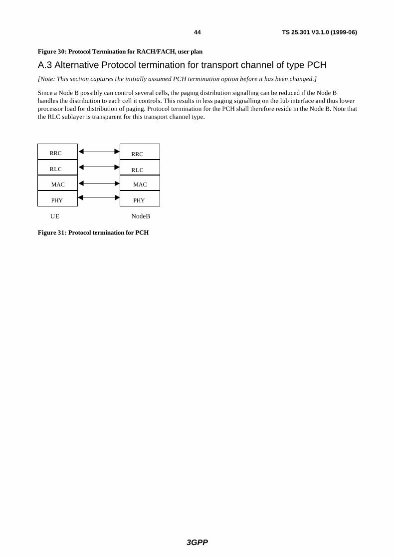
3GPP
44 TS 25.301 V3.1.0 (1999-06)
Figure 30: Protocol Termination for RACH/FACH, user plan
A.3 Alternative Protocol termination for transport channel of type PCH [Note: This section captures the initially assumed PCH termination option before it has been changed.]
Since a Node B possibly can control several cells, the paging distribution signalling can be reduced if the Node B handles the distribution to each cell it controls. This results in less paging signalling on the Iub interface and thus lower processor load for distribution of paging. Protocol termination for the PCH shall therefore reside in the Node B. Note that the RLC sublayer is transparent for this transport channel type.
UE NodeB
RLC
MAC
PHY
RLC
MAC
PHY
RRC RRC
Figure 31: Protocol termination for PCH
3GPP
45 TS 25.301 V3.1.0 (1999-06)
Annex B (informative): Overview of CPCH Channel Access Procedure
[Note: This description needs to be reviewed and completed in future meetings.]
B.1 Overview of PHY and MAC
• The CPCH Random Access procedure is based on a DSMA-CD multiple access method.
• Access Preamble (AP) signatures are used to identify the particular CPCH resource which the UE is attempting to access.
• The access preamble ramp -up is similar to the RACH mechanism. However, there is a collision detection/resolution mechanism that follows the access preamble ramp -up. The UEs receive AICH indicating their success in ramp -up and granting accessing to the CPCH. The UEs will refrain requesting a busy CPCH channel. All UEs log and timestamp all received AICHs in a recency table. This table allows the UE to estimate the probability that a given CPCH is unused at any particular time. This models the DSMA-CD protocol.
• Layer 1 in Node B is responsible for Call Admission Control and resource management for the CPCH set assigned by the RNC to Node B.
B.2 Temporal Sequence of CPCH Events for Normal Access
The following describes the normal CPCH access procedure and entails both the UE and UTRAN side:
1. The UE will initiate RRC connection procedure and transition to the RRC connection mode. Transport Format Sets will be assigned to the UE by UTRAN, by RAB set-up.
2. The UE enters the idle mode where it performs the following tasks:
• monitoring the CPCH cell resources and parameters in BCCH,
• execution of the RLC ARQ procedure,
• monitoring of the AICH/ASSIGN to update CPCH availability table,
• reporting of traffic measurement Data as required by UTRAN.
3. UTRAN will be performing the following tasks in the idle mode:
• collection of traffic measurements from the UEs and the cells,
• reassignment of priorities to all UE RABs to maintain QoS,
• allocation of CPCHs to cells based on traffic measurements (cell demand),
• calculation of persistency values from all CPCHs to balance loads and relieve congestion.
• UTRAN broadcasts the CPCH parameters and resources on BCCH. The UTRAN transmits the system messages which contain the following information:
For each CPCH physical channel allocated to a cell the following parameters are included in the System Information message:
• CPCH Set ID to which this CPCH belongs.
• UL Access Preamble (AP) code (256 chip)
• DL AICH preamble code (256 chip)
• UL CD preamble code (256 chip)
• DL ASSIGN preamble code (256 chip)
• CPCH UL scrambling code (40,960 chip)

3GPP
46 TS 25.301 V3.1.0 (1999-06)
• CPCH UL channelisation code (variable, data rate dependant)
• CPCCH DL channelisation code (512 chip) [FFS]
• Data rate (spreading factor) (64, 128Kbps, 256Kbps, 384Kbps, or 2 Mbps)
• N_frames_max: Maximum packet length in frames [2-64] [FFS]
• Persistency value: assigned by RNC to control congestion and for load balancing
• Signature set: set of preamble signatures (up to 16, 16 bits long) for AP to access this CPCH

3GPP
47 TS 25.301 V3.1.0 (1999-06)
History
Document history
Date Version Comment
January 1999 0.0.1 Initial version based on ARIB Radio Interface Protocol Architecture, V1.0.0 (Tdoc TSG-RAN WG2 008/99) and ETSI UMTS YY.01, V1.0.3 (Tdoc TSG-RAN WG2 011/99) as agreed at the 3GPP TSG RAN WG2 meeting #1, Helsinki, Jan. 20-22, 1999. Revision markers with respect to YY.01.
February 1999 0.0.2 Document layout updated according to 3GPP template. All revisions shown in V0.0.1 accepted.. Some editorial corrections/updates. Incorporation of changes agreed in e-mail discussions regarding padding and dynamic scheduling functions of MAC and regarding DSCH.
February 1999 0.1.0 Approved by TSG RAN WG2. Document presented to 3GPP TSG RAN #2, Fort Lauderdale, March 2-4, 1999.
March 1999 0.1.1 Updated according to decisions agreed at 3GPP TSG RAN WG2 meeting #2, Stockholm, March 8-12.
April 1999 0.1.2 Updated according to e-mail comments. Document presented at 3GPP TSG RAN WG2 meeting #3, Yokohama, April 13-16.
April 1999 0.1.3 Updated according to decisions agreed at 3GPP TSG RAN WG2 meeting #3, Yokohama, April 13-16.
April 1999 0.2.0 Approved by TSG RAN WG2. Document presented to 3GPP TSG RAN #3 for approval, Yokohama, April 21-23, 1999.
April 1999 3.0.0 Approved by TSG-RAN as TS 25.301 V3.0.0
May 1999 3.0.1 Inclusion of editorial changes requested/agreed at RAN meeting #3.
June 1999 3.1.0 Inclusion of CRs agreed by TSG-RAN, 25.301-001, 25.301-002, 25.301-003r1. Inclusion of ETSI template.
Rapporteur for TS 25.301 is:
Wolfgang Granzow Ericsson Eurolab Germany
Tel. : +49 911 5217 308 Fax : +49 911 5217 950 Email : [email protected]
This document is written in Microsoft Word version 7.0/97.