3M Sound Level Meter 1100 en 2100
25
3M Occupational Health & Environmental Safety Division 1100/2100 Sound Level Meter Models Functionality 1100/2100 SLM User Manual Easy to Use
Transcript of 3M Sound Level Meter 1100 en 2100
8/9/2019 3M Sound Level Meter 1100 en 2100
http://slidepdf.com/reader/full/3m-sound-level-meter-1100-en-2100 1/24
3M Occupational Health & Environmental Safety Division1100/2100 Sound Level Meter Models
Functionality1100/2100 SLM User Manual
Easy to Use
8/9/2019 3M Sound Level Meter 1100 en 2100
http://slidepdf.com/reader/full/3m-sound-level-meter-1100-en-2100 2/24
056-652, Rev.D 1100/2100 SLM models
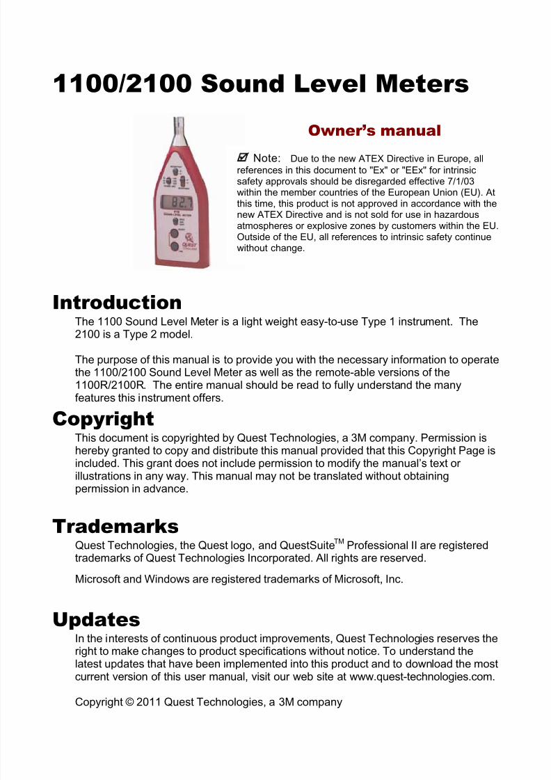
1100/2100 Sound Level Meters
Owner’s manual
IntroductionThe 1100 Sound Level Meter is a light weight easy-to-use Type 1 instrument. The2100 is a Type 2 model.
The purpose of this manual is to provide you with the necessary information to operatethe 1100/2100 Sound Level Meter as well as the remote-able versions of the1100R/2100R. The entire manual should be read to fully understand the manyfeatures this instrument offers.
CopyrightThis document is copyrighted by Quest Technologies, a 3M company. Permission ishereby granted to copy and distribute this manual provided that this Copyright Page isincluded. This grant does not include permission to modify the manual’s text orillustrations in any way. This manual may not be translated without obtainingpermission in advance.
TrademarksQuest Technologies, the Quest logo, and QuestSuite
TM
Professional II are registeredtrademarks of Quest Technologies Incorporated. All rights are reserved.
Microsoft and Windows are registered trademarks of Microsoft, Inc.
UpdatesIn the interests of continuous product improvements, Quest Technologies reserves theright to make changes to product specifications without notice. To understand thelatest updates that have been implemented into this product and to download the mostcurrent version of this user manual, visit our web site at www.quest-technologies.com.
Copyright © 2011 Quest Technologies, a 3M company
Note: Due to the new ATEX Directive in Europe, all
references in this document to "Ex" or "EEx" for intrinsicsafety approvals should be disregarded effective 7/1/03within the member countries of the European Union (EU). Atthis time, this product is not approved in accordance with thenew ATEX Directive and is not sold for use in hazardousatmospheres or explosive zones by customers within the EU.Outside of the EU, all references to intrinsic safety continuewithout change.
8/9/2019 3M Sound Level Meter 1100 en 2100
http://slidepdf.com/reader/full/3m-sound-level-meter-1100-en-2100 3/24
Table of Contents
056-652, Rev.D 1100/2100 SLM models
ii
Table of contentsIntroduction ...................................................................................................................... 1
1100/2100 Models .............................................................................................................. 1
Getting Started ................................................................................................................. 3
The Display ........................................................................................................................ 3
Meter Controls .................................................................................................................... 3
OFF/SPL/MAX Switch ..................................................................................................... 3"F" (FAST) / "S" (SLOW) RESPONSE Switch .................................................................. 3
Overload Detection and Underrange .................................................................................. 5
Output Jack ........................................................................................................................ 5 DC Output Function ....................................................................................................... 5
AC Output Function ........................................................................................................ 5Checking the battery ........................................................................................................ 6
Battery Check ..................................................................................................................... 6
Battery Replacement .......................................................................................................... 6
Rechargeable Batteries ...................................................................................................... 6
Calibrate ............................................................................................................................ 6
Changing the Calibration Level ........................................................................................... 6
Calibration .......................................................................................................................... 7
Calibration Check ............................................................................................................... 7
Operating and Measurements ......................................................................................... 8
Operation ........................................................................................................................... 8
Meter/Microphone Placement ............................................................................................. 8
Background Noise .............................................................................................................. 8
Background Noise Example ............................................................................................... 9
Windscreen Effects............................................................................................................. 9
Chart Recording/Datalogging ........................................................................................... 10
Technical Information .................................................................................................... 11
Principles of Operation ..................................................................................................... 11
Microphone ...................................................................................................................... 12
Microphone response time ............................................................................................... 12
Microphone preamplifier extension cables ........................................................................ 13
Input Buffer Circuitry ......................................................................................................... 13
8/9/2019 3M Sound Level Meter 1100 en 2100
http://slidepdf.com/reader/full/3m-sound-level-meter-1100-en-2100 4/24
Table of Contents
056-652, Rev.D 1100/2100 SLM models
iii
Weighting Characteristics ................................................................................................. 14
Internal Electrical Noise .................................................................................................... 14
Tone Burst Response ....................................................................................................... 15
Specifications ................................................................................................................. 16
Accessories .................................................................................................................... 18
Quest Service ................................................................................................................. 19
Contacting Quest Technologies ........................................................................................ 19
International customers .................................................................................................... 19
FiguresFigure 1-1: Sound Level Meter 2100 model ....................................................................1
Figure 1-2: Model 1100R/2100R ....................................................................................2 Figure 2: Keypad/Control switches identified ...............................................................4
Figure 3: Output jack connections ...............................................................................5 Figure 4: Effects of background noise ...........................................................................9 Figure 5: Effects of WS-7 ...........................................................................................9
Figure 6: Block diagram of the model 1100/2100’s circuit board .................................. 11
Figure 7: Typical microphone response Type 1 ......................................................... 12
Figure 8: Typical microphone response Type 2 ......................................................... 12 Figure 9: Frequency/Amplitude limitations with extension cables ................................ 13
Figure 10: Input buffer circuitry ................................................................................... 13
Figure 11: A & C Weighting ........................................................................................ 14
Figure 12: Fast response ........................................................................................... 15
Figure 13: Slow response .......................................................................................... 15
8/9/2019 3M Sound Level Meter 1100 en 2100
http://slidepdf.com/reader/full/3m-sound-level-meter-1100-en-2100 5/24
1 Introduction 1100/2100 Models
056-652, Rev.D 1100/2100 SLM models
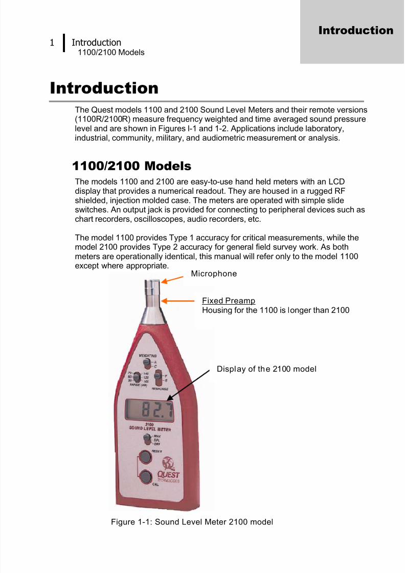
Introduction The Quest models 1100 and 2100 Sound Level Meters and their remote versions
(1100R/2100R) measure frequency weighted and time averaged sound pressurelevel and are shown in Figures l-1 and 1-2. Applications include laboratory,industrial, community, military, and audiometric measurement or analysis.
1100/2100 ModelsThe models 1100 and 2100 are easy-to-use hand held meters with an LCDdisplay that provides a numerical readout. They are housed in a rugged RF
shielded, injection molded case. The meters are operated with simple slideswitches. An output jack is provided for connecting to peripheral devices such aschart recorders, oscilloscopes, audio recorders, etc.
The model 1100 provides Type 1 accuracy for critical measurements, while themodel 2100 provides Type 2 accuracy for general field survey work. As bothmeters are operationally identical, this manual will refer only to the model 1100except where appropriate.
Figure 1-1: Sound Level Meter 2100 model
Introduction
Microphone
Fixed PreampHousing for the 1100 is longer than 2100
Display of the 2100 model
8/9/2019 3M Sound Level Meter 1100 en 2100
http://slidepdf.com/reader/full/3m-sound-level-meter-1100-en-2100 6/24
2 Introduction 1100/2100 Models
056-652, Rev.D 1100/2100 SLM models
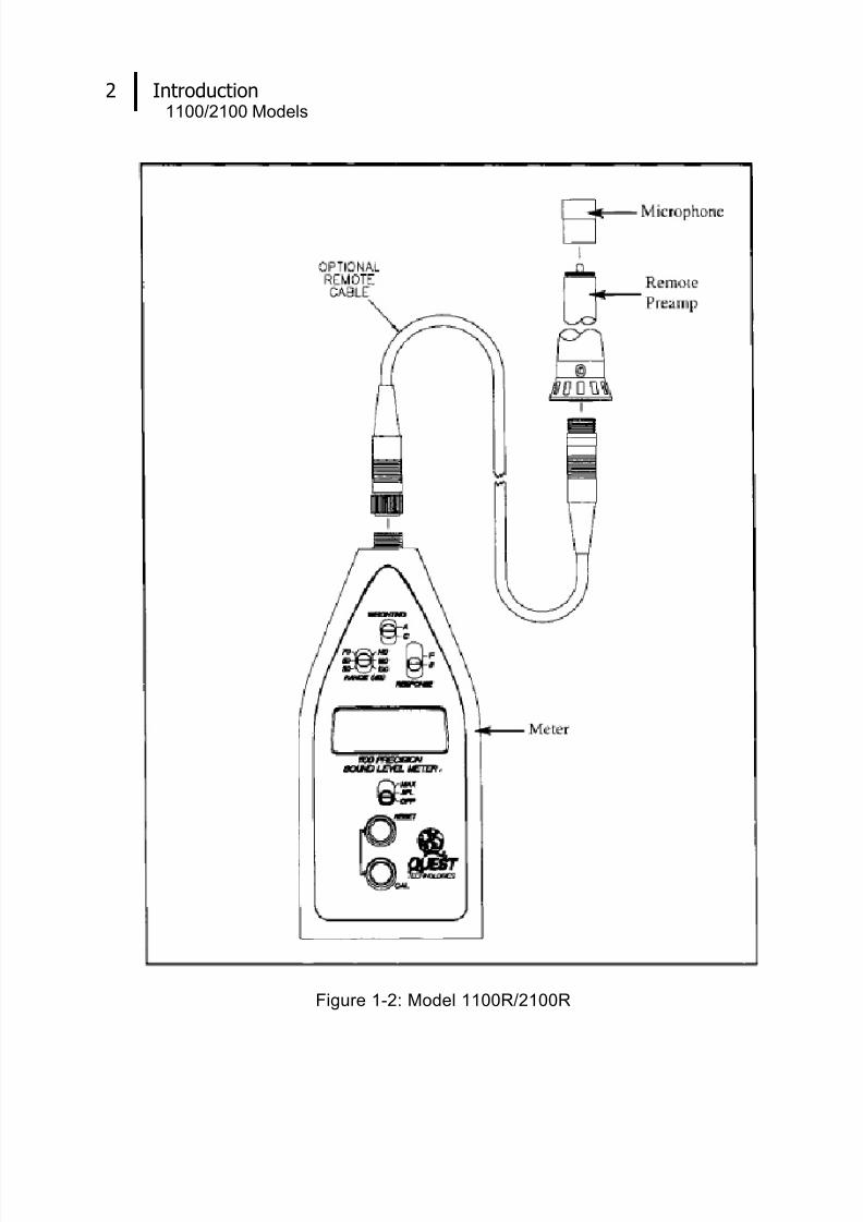
Figure 1-2: Model 1100R/2100R
8/9/2019 3M Sound Level Meter 1100 en 2100
http://slidepdf.com/reader/full/3m-sound-level-meter-1100-en-2100 7/24
3 Getting Started The Display
056-652, Rev.D 1100/2100 SLM models
Getting Started
The DisplayThe LCD display provides a numeric readout of sound level in 0.1 dB incrementsalong with a LOBAT (low battery) indicator. In the SPL mode the numeric displayprovides a reading of the maximum sound pressure level measured during theprevious second. In the MAX mode the displayholds the highest reading encountered since the meter was placed in MAX, orsince the last time RESET was pressed.
The LOBAT indicator will light when the battery voltage is too low to allow an
accurate reading.
The display will show a + sign when signal peaks cause an overload condition inthe electronics. This indicator signals the user to switch to the next higher range toprevent erroneous readings.The display will show "Ur" if signal levels are too low to provide an accuratereading. This indicator signals the user to switch to a lower range setting.
Meter Controls
OFF/SPL/MAX Switch
With the switch set to SPL the meter continuously displays sound level,automatically updating the current reading at a rate of once per second.Setting the switch to MAX causes the display to hold the highest SPLencountered thus far. As a higher SPL occurs, the display changes to showthe new value. To reset the value stored, press and hold the RESET buttonfor a few seconds, then release. This will erase the previous MAX value(and display the current value) prior to taking new readings. For responsetimes see Figures 7 and 8.
"F" (FAST) / "S" (SLOW) RESPONSE Switch
The RESPONSE switch controls the rate at which the meter responds tochanging input signals. Most sound measurements are done with theresponse set to SLOW. The FAST response is generally used whenmeasuring short duration noises such as moving vehicles.
The RESPONSE switch posit ions are as fol lows:
• FAST - 125 millisecond time constant. (See Figure 12).
• SLOW - 1 second time constant. (See Figure 13).
Getting Started

8/9/2019 3M Sound Level Meter 1100 en 2100
http://slidepdf.com/reader/full/3m-sound-level-meter-1100-en-2100 8/24
4 Getting Started Meter Controls
056-652, Rev.D 1100/2100 SLM models
WEIGHTING A/C SwitchThe WEIGHTING switch controls the frequency response of the meter.Weightings A or C may be selected. See “Microphone preamplifier”, page13 Weighting Characteristics, for further information.
RANGE (dB) SwitchThe displayed range of the model 1100 is 70 dB and is switchable between30-100 dB, 50-120 dB, and 70-140 dB. After switching ranges allow severalseconds for the meter electronics to stabilize.
RESET Button
This button is primarily used to clear the MAX sound level when theinstrument is in the MAX mode. Pressing the RESET button for at least ahalf second will cause a reset of MAX. If observation of the changing SoundPressure Level is desired, while in the MAX mode, the RESET button maybe held down for as long as the SPL display is desired. Upon release of theRESET button MAX will be reset and the 1100 will resume accumulatingMAX. The RESET button also functions as an up arrow during setup (see“Changing the Calibration Level”, page 6).
CAL Button
This button is primarily used to enter the Calibration routine, but it alsofunctions as a down arrow during setup (see “Changing the CalibrationLevel”, page 6).
Figure 2: Keypad/Control switches identified
Weighting A or C
Response Fast or Slow
Range
30 to 140 dBA
Measurement SPL or MAX
8/9/2019 3M Sound Level Meter 1100 en 2100
http://slidepdf.com/reader/full/3m-sound-level-meter-1100-en-2100 9/24
5 Getting Started Overload Detection and Underrange
056-652, Rev.D 1100/2100 SLM models
Overload Detection and UnderrangeThe Overload Indicator is displayed whenever the incoming signal saturates
(overloads) the circuitry. It is the + sign on the left side of the display. If theoverload indicator is on while taking measurements in a Low range, increasingthe dB Range switch should cause the overload to disappear. If you are alreadyon the highest range setting and an overload condition still exists, the sound levelthat you are measuring is beyond the capability of the 1100 due to either anextremely high rms value or a high crest factor (peak to rms ratio).
Underrange is indicated by a "Ur " in the display. When the noise level dropsbelow the bottom of the range, this indicator will turn on. Switching to a lowerrange will turn it off.
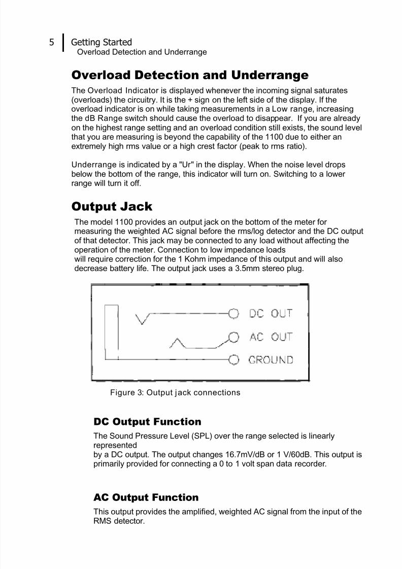
Output JackThe model 1100 provides an output jack on the bottom of the meter formeasuring the weighted AC signal before the rms/log detector and the DC outputof that detector. This jack may be connected to any load without affecting theoperation of the meter. Connection to low impedance loadswill require correction for the 1 Kohm impedance of this output and will alsodecrease battery life. The output jack uses a 3.5mm stereo plug.
Figure 3: Output jack connections
DC Output Function
The Sound Pressure Level (SPL) over the range selected is linearlyrepresentedby a DC output. The output changes 16.7mV/dB or 1 V/60dB. This output isprimarily provided for connecting a 0 to 1 volt span data recorder.
AC Output FunctionThis output provides the amplified, weighted AC signal from the input of theRMS detector.
8/9/2019 3M Sound Level Meter 1100 en 2100
http://slidepdf.com/reader/full/3m-sound-level-meter-1100-en-2100 10/24
6 Checking the battery Battery Check
056-652, Rev.D 1100/2100 SLM models
Checking the battery
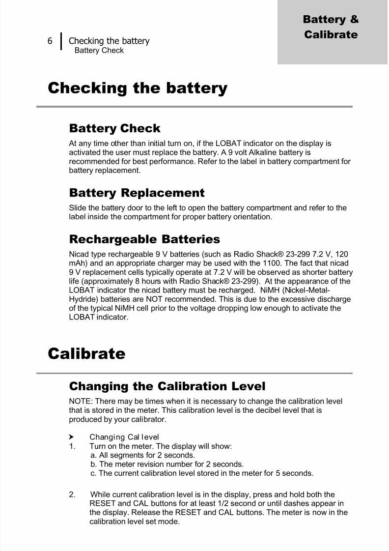
Battery Check At any time other than initial turn on, if the LOBAT indicator on the display isactivated the user must replace the battery. A 9 volt Alkaline battery isrecommended for best performance. Refer to the label in battery compartment forbattery replacement.
Battery ReplacementSlide the battery door to the left to open the battery compartment and refer to thelabel inside the compartment for proper battery orientation.
Rechargeable BatteriesNicad type rechargeable 9 V batteries (such as Radio Shack® 23-299 7.2 V, 120mAh) and an appropriate charger may be used with the 1100. The fact that nicad9 V replacement cells typically operate at 7.2 V will be observed as shorter batterylife (approximately 8 hours with Radio Shack® 23-299). At the appearance of the
LOBAT indicator the nicad battery must be recharged. NiMH (Nickel-Metal-Hydride) batteries are NOT recommended. This is due to the excessive dischargeof the typical NiMH cell prior to the voltage dropping low enough to activate theLOBAT indicator.
Calibrate
Changing the Calibration LevelNOTE: There may be times when it is necessary to change the calibration levelthat is stored in the meter. This calibration level is the decibel level that isproduced by your calibrator.
Changing Cal level 1. Turn on the meter. The display will show:
a. All segments for 2 seconds.b. The meter revision number for 2 seconds.c. The current calibration level stored in the meter for 5 seconds.
2. While current calibration level is in the display, press and hold both theRESET and CAL buttons for at least 1/2 second or until dashes appear inthe display. Release the RESET and CAL buttons. The meter is now in thecalibration level set mode.
Battery &
Calibrate

8/9/2019 3M Sound Level Meter 1100 en 2100
http://slidepdf.com/reader/full/3m-sound-level-meter-1100-en-2100 11/24
Checking the batteryCalibration
056-652, Rev.D 1100/2100 SLM models
7
NOTE: If the RESET and CAL buttons are continuously held down afterthe dashes appear, the unit will interpret this as a command to exitcalibration level set mode and exit without changing the calibration level.
3. To edit the level, use the RESET key to increase the value and the CAL keyto decrease the value. Edit the value to match your calibrators output.
4. When the desired calibration level is displayed, press and hold both theRESET and CAL buttons until dashes appear on the display. The newcalibration level is now stored in the instrument's memory and will not haveto be changed again unless an alternate calibrator is used.
Calibration
The model 1100 may be calibrated in any range based on your calibrator's output.There is no warm up period required, but for maximum accuracy calibration of themodel 1100 should be performed at the temperature of the environment to bemeasured. To calibrate, perform the following procedure using a Quest calibrator.
It is recommended that calibration be performed before each use.
Calibration
1. Check to see that the LOB AT indicator is not on.
2. Check to see that the calibrator SPL output matches the calibration level stored in the meter. If it does not, use procedure outlined in “Changing thecalibration level”
NOTE: Failure to match calibrator output level to calibration level stored inthe 1100 will result in erroneous SPL reading.
3. Turn the calibrator ON. If optional, set the frequency to 1 KHz.
4. Place the black adapter ring fully onto the microphone.
5. Set the model 1100 to SPL, SLOW or FAST, and A or C weighting. Set
the measuring range so that the calibration level falls within it.
NOTE: Attempting to calibrate out of range will result in an "Err" on thedisplay and a failed calibration. The previous calibration data will remain inthe instrument.
6. Press the CAL button. “CAL” will appear on the display followed bymoving dashes. After about 2 seconds the display will show either a "P" forpass or an "F" for fail. If the calibration fails, check settings and repeatprocedure.
Calibration CheckIt is a good idea to check calibration after use. To do so, perform the previoussteps 1 through 5. Observe the meter display, it should read the calibrator level+/- 0.5 dB. If out of tolerance, run calibration procedure described above in“Calibration”.
8/9/2019 3M Sound Level Meter 1100 en 2100
http://slidepdf.com/reader/full/3m-sound-level-meter-1100-en-2100 12/24
8 Operating and Measurements Operation
056-652, Rev.D 1100/2100 SLM models
Operating and Measurements
OperationBefore taking measurements with the model 1100, there is aseries of quick checks and considerations that should beperformed or noted. After switching the unit ON, check for aLOBAT indication on the display, replace battery if necessary.(See “Battery check”, page 6).
Although the model 1100 will maintain accurate calibrationover a long period of time, the calibration should be checkedand the meter re-calibrated, if necessary, before each use. Thecalibration should also be checked after each use. (See“Calibration check”, page 7). Set the RESPONSE,WEIGHTING, and RANGE (dB) switches as needed. Hold,set, or tripod mount the meter in the desired location. If a MAXmeasurement is needed, be sure to reset the meter beforetaking the measurements. It is always a good idea todocument all measurement conditions and meter settings forpossible future reference.
Meter/Microphone PlacementWhenever possible, the meter should be tripod-mounted in arelatively open area to minimize reflections from the body orother large reflective structures. Avoid placement against awall or in a corner. A threaded bushing on the back will accepta standard 1/4-20 tripod fitting.
The microphone cartridges used on the models 1100 and 2100are free-field microphones. Point the meter directly at the noisesource (0 degrees).
Random incidence measurements may be taken with the 1100if the plastic random incidence corrector supplied with theBK4936 microphone is used. The random incidence correctoris a black plastic lipped sleeve packed in the BK4936 packingcontainer. To attach the corrector, position the end of thesleeve without the lip over the grid of the microphone andgently press down until a snap fit is achieved. Point themicrophone approximately 70° to the direction of the sound.
Background NoiseBackground noise can cause considerable error inmeasurement when its intensity is close to that of a particularsound source of interest. When it is not possible to eliminate orreduce the background noise, use the curve shown in Figure 4to correct for the effect of the background noise on themeasurement.
Operating &
Measurements
8/9/2019 3M Sound Level Meter 1100 en 2100
http://slidepdf.com/reader/full/3m-sound-level-meter-1100-en-2100 13/24
9 Operating and Measurements Background Noise Example
056-652, Rev.D 1100/2100 SLM models
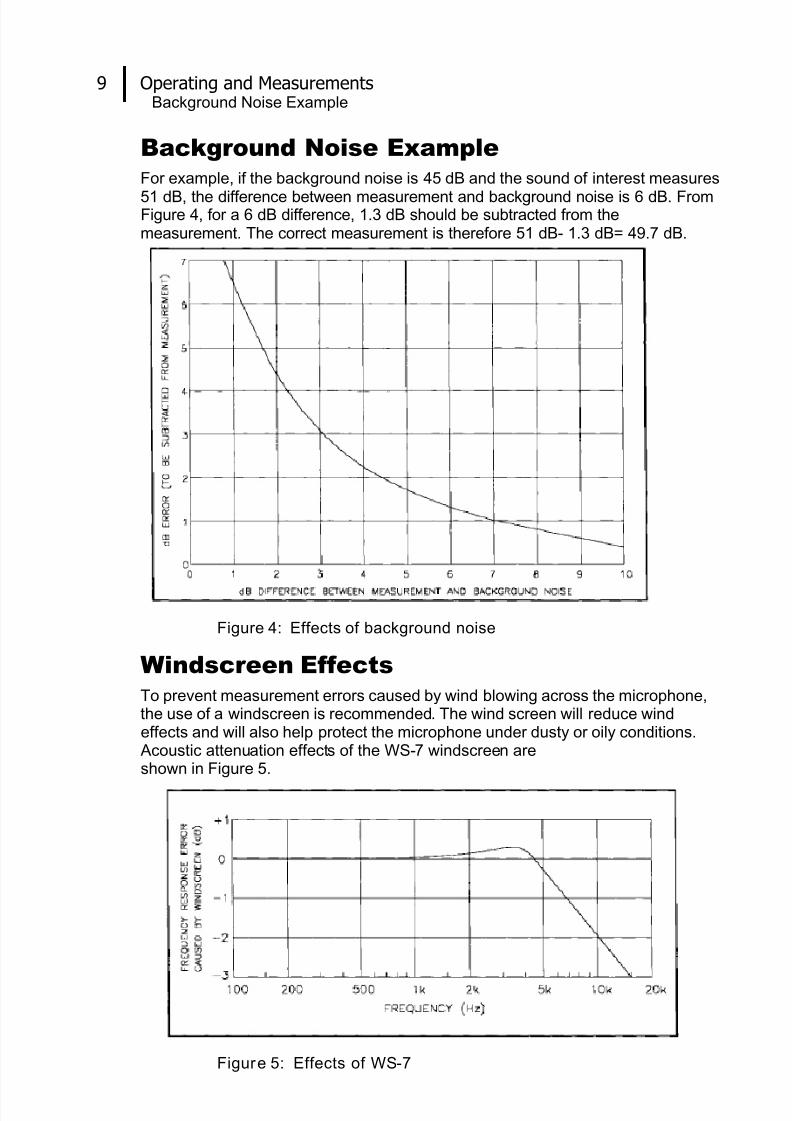
Background Noise ExampleFor example, if the background noise is 45 dB and the sound of interest measures
51 dB, the difference between measurement and background noise is 6 dB. FromFigure 4, for a 6 dB difference, 1.3 dB should be subtracted from themeasurement. The correct measurement is therefore 51 dB- 1.3 dB= 49.7 dB.
Figure 4: Effects of background noise
Windscreen EffectsTo prevent measurement errors caused by wind blowing across the microphone,the use of a windscreen is recommended. The wind screen will reduce windeffects and will also help protect the microphone under dusty or oily conditions.
Acoustic attenuation effects of the WS-7 windscreen areshown in Figure 5.
Figure 5: Effects of WS-7
8/9/2019 3M Sound Level Meter 1100 en 2100
http://slidepdf.com/reader/full/3m-sound-level-meter-1100-en-2100 14/24
10 Operating and Measurements Chart Recording/Datalogging
056-652, Rev.D 1100/2100 SLM models
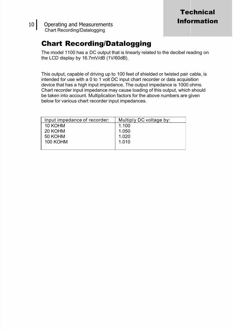
Chart Recording/DataloggingThe model 1100 has a DC output that is linearly related to the decibel reading on
the LCD display by 16.7mV/dB (1V/60dB).
This output, capable of driving up to 100 feet of shielded or twisted pair cable, isintended for use with a 0 to 1 volt DC input chart recorder or data acquisitiondevice that has a high input impedance. The output impedance is 1000 ohms.Chart recorder input impedance may cause loading of this output, which shouldbe taken into account. Multiplication factors for the above numbers are givenbelow for various chart recorder input impedances.
Input impedance of recorder: Multiply DC voltage by:
10 KOHM20 KOHM50 KOHM100 KOHM
1.1001.0501.0201.010
Technical
Information
8/9/2019 3M Sound Level Meter 1100 en 2100
http://slidepdf.com/reader/full/3m-sound-level-meter-1100-en-2100 15/24
11 Technical Information Principles of Operation
056-652, Rev.D 1100/2100 SLM models
Technical Information
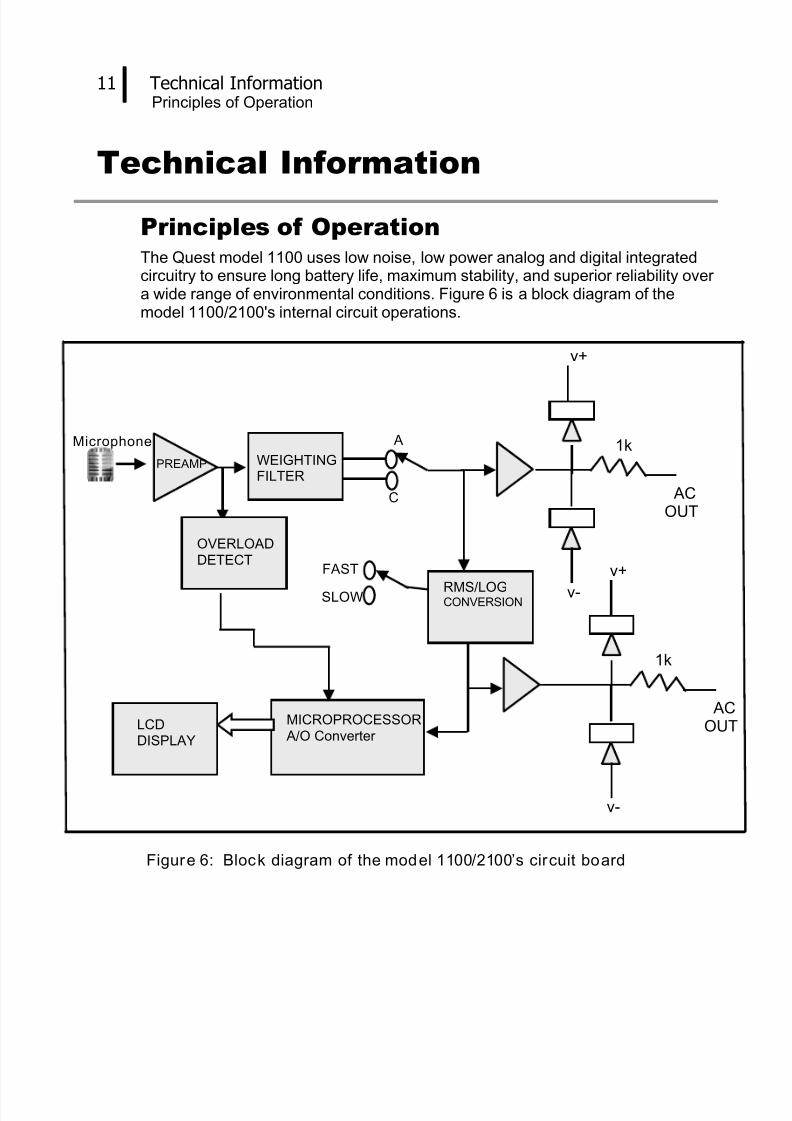
Principles of OperationThe Quest model 1100 uses low noise, low power analog and digital integratedcircuitry to ensure long battery life, maximum stability, and superior reliability overa wide range of environmental conditions. Figure 6 is a block diagram of themodel 1100/2100's internal circuit operations.
Figure 6: Block diagram of the model 1100/2100’s circuit board
FAST
SLOW
Microphone PREAMP
RMS/LOGCONVERSION
A
C
v+
v-
1k
ACOUT
WEIGHTINGFILTER
MICROPROCESSOR A/O Converter
LCDDISPLAY
OVERLOADDETECT
v+
v-
1k
ACOUT
8/9/2019 3M Sound Level Meter 1100 en 2100
http://slidepdf.com/reader/full/3m-sound-level-meter-1100-en-2100 16/24
12 Technical Information Microphone
056-652, Rev.D 1100/2100 SLM models
Microphone
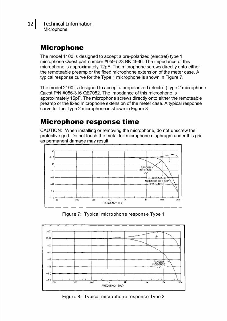
The model 1100 is designed to accept a pre-polarized (electret) type 1microphone Quest part number #059-523 BK 4936. The impedance of thismicrophone is approximately 12pF. The microphone screws directly onto eitherthe remoteable preamp or the fixed microphone extension of the meter case. Atypical response curve for the Type 1 microphone is shown in Figure 7.
The model 2100 is designed to accept a prepolarized (electret) type 2 microphoneQuest P/N #056-316 QE7052. The impedance of this microphone isapproximately 15pF. The microphone screws directly onto either the remoteablepreamp or the fixed microphone extension of the meter case. A typical responsecurve for the Type 2 microphone is shown in Figure 8.
Microphone response timeCAUTION: When installing or removing the microphone, do not unscrew theprotective grid. Do not touch the metal foil microphone diaphragm under this gridas permanent damage may result.
Figure 7: Typical microphone response Type 1
Figure 8: Typical microphone response Type 2

8/9/2019 3M Sound Level Meter 1100 en 2100
http://slidepdf.com/reader/full/3m-sound-level-meter-1100-en-2100 17/24
Technical Information Microphone preamplifier extension cables
056-652, Rev.D 1100/2100 SLM models
13
Microphone preamplifier extension cablesOn 1100R (Remote) units the preamplifier is removable by unscrewing the blackplastic collar below the preamplifier housing. The 1100 will drive up to a 10 footcable with minimal loss. Quest offers the following lengths of remote cable for usewith the 1100:
• #59-899 ICM-2 Microphone Cable (2 foot length)
• #59-733 ICM-10 Microphone Cable (10 foot length)
• #59-734 ICM-50 Microphone Cable (50 foot length)The calibration level at 1 kHz is affected by less than 0.1 dB with the insertion ofeither of these cables. Therefore, there is no need to recalibrate when the cable isattached.
Figure 9: Frequency/Ampli tude limitations with extension cables
Input Buffer CircuitryThe high impedance input circuitry of the 1100 will accept up to a 2.0 volt RMSsignal. With the microphone and preamp removed, other transducer devices maybe connected to give a dB readout on the meter. To remove the preamplifierunscrew the black plastic collar below the preamp housing. Only use pins 1 and
3 for the AC signal input. NEVER connect to pins 2 and 4. To input an electricalsignal requires a special connector, Quest part number 14-739. Figure 10 showsthe function of each of the pins within the meter input connector.
Figure 10: Input buffer circuitry
8/9/2019 3M Sound Level Meter 1100 en 2100
http://slidepdf.com/reader/full/3m-sound-level-meter-1100-en-2100 18/24
Technical Information Weighting Characteristics
056-652, Rev.D 1100/2100 SLM models
14
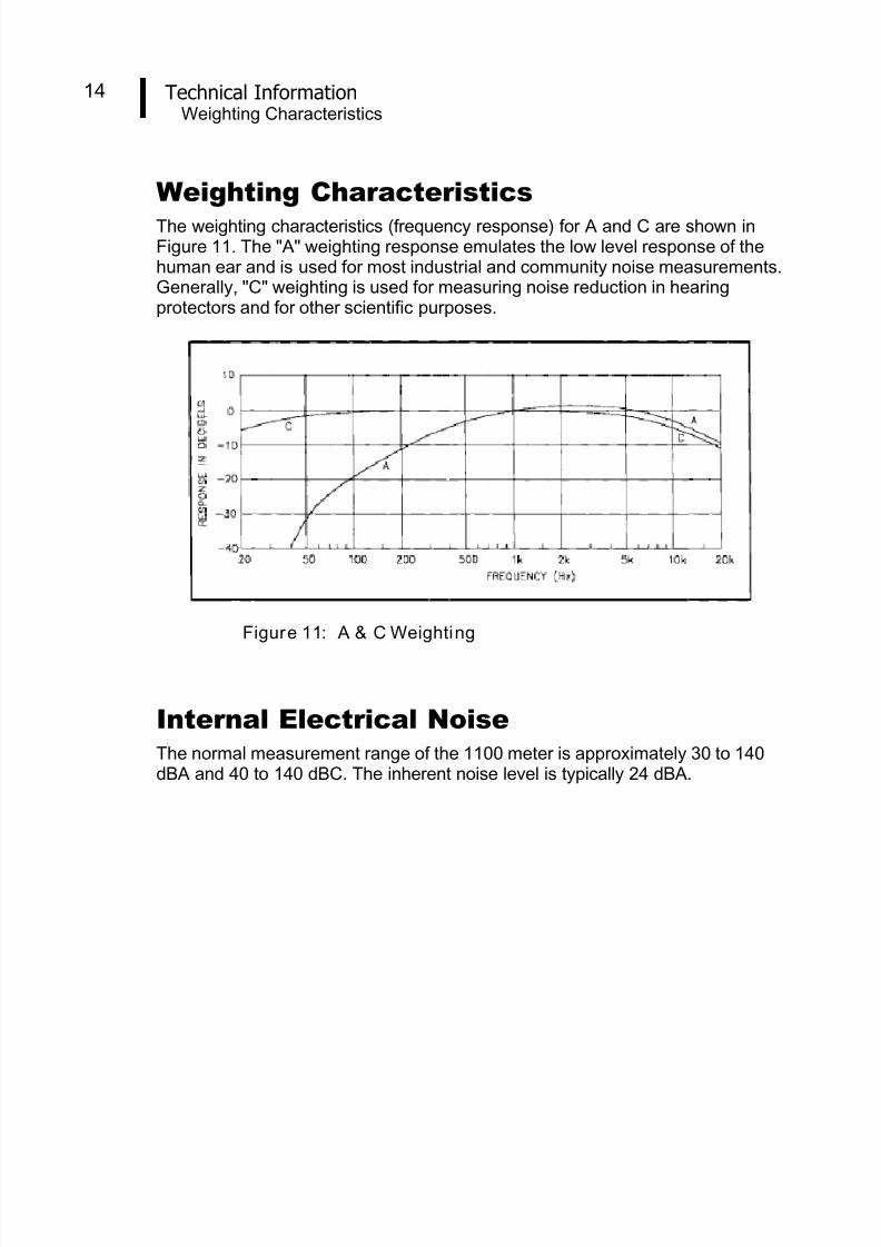
Weighting CharacteristicsThe weighting characteristics (frequency response) for A and C are shown inFigure 11. The "A" weighting response emulates the low level response of thehuman ear and is used for most industrial and community noise measurements.Generally, "C" weighting is used for measuring noise reduction in hearingprotectors and for other scientific purposes.
Figure 11: A & C Weighting
Internal Electrical NoiseThe normal measurement range of the 1100 meter is approximately 30 to 140dBA and 40 to 140 dBC. The inherent noise level is typically 24 dBA.
8/9/2019 3M Sound Level Meter 1100 en 2100
http://slidepdf.com/reader/full/3m-sound-level-meter-1100-en-2100 19/24
Technical InformationTone Burst Response
056-652, Rev.D 1100/2100 SLM models
15
Tone Burst Response
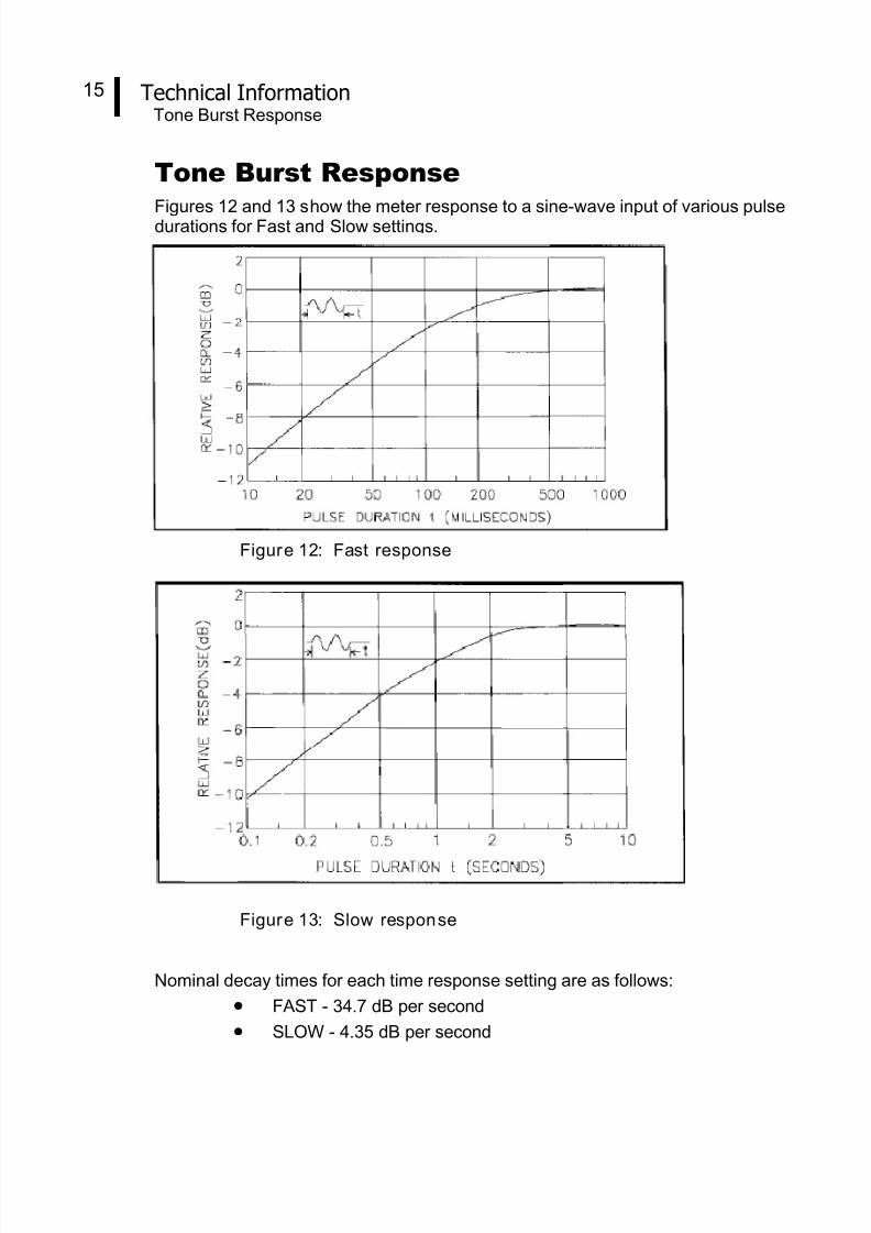
Figures 12 and 13 show the meter response to a sine-wave input of various pulsedurations for Fast and Slow settings.
Figure 12: Fast response
Figure 13: Slow response
Nominal decay times for each time response setting are as follows:
• FAST - 34.7 dB per second
• SLOW - 4.35 dB per second
8/9/2019 3M Sound Level Meter 1100 en 2100
http://slidepdf.com/reader/full/3m-sound-level-meter-1100-en-2100 20/24
SpecificationsTone Burst Response
056-652, Rev.D 1100/2100 SLM models
16
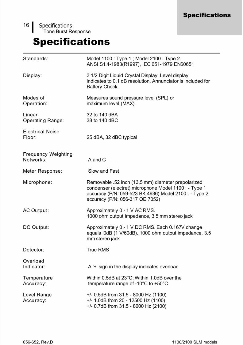
Specifications
Standards: Model 1100 : Type 1 ; Model 2100 : Type 2 ANSI S1.4-1983(R1997), IEC 651-1979 EN60651
Display: 3 1/2 Digit Liquid Crystal Display. Level displayindicates to 0.1 dB resolution. Annunciator is included forBattery Check.
Modes of Measures sound pressure level (SPL) orOperation: maximum level (MAX).
Linear 32 to 140 dBA
Operating Range: 38 to 140 dBC
Electrical NoiseFloor : 25 dBA, 32 dBC typical
Frequency WeightingNetworks: A and C
Meter Response: Slow and Fast
Microphone: Removable .52 inch (13.5 mm) diameter prepolarizedcondenser (electret) microphone Model 1100 : - Type 1accuracy (P/N: 059-523 BK 4936) Model 2100 : - Type 2accuracy (P/N: 056-317 QE 7052)
AC Output : Approximately 0 - 1 V AC RMS.1000 ohm output impedance, 3.5 mm stereo jack
DC Output: Approximately 0 - 1 V DC RMS. Each 0.167V changeequals l0dB (1 V/60dB). 1000 ohm output impedance, 3.5mm stereo jack
Detector: True RMS
OverloadIndicator: A '+' sign in the display indicates overload
Temperature Within 0.5dB at 23°C; Within 1.0dB over the Accuracy: temperature range of -10°C to +50°C
Level Range +/- 0.5dB from 31.5 - 8000 Hz (1100)
Accuracy: +/- 1.0dB from 20 - 12500 Hz (1100)+/- 0.7dB from 31.5 - 8000 Hz (2100)
Specifications
8/9/2019 3M Sound Level Meter 1100 en 2100
http://slidepdf.com/reader/full/3m-sound-level-meter-1100-en-2100 21/24
Technical InformationSpecificationsTone Burst Response
056-652, Rev.D 1100/2100 SLM models
17
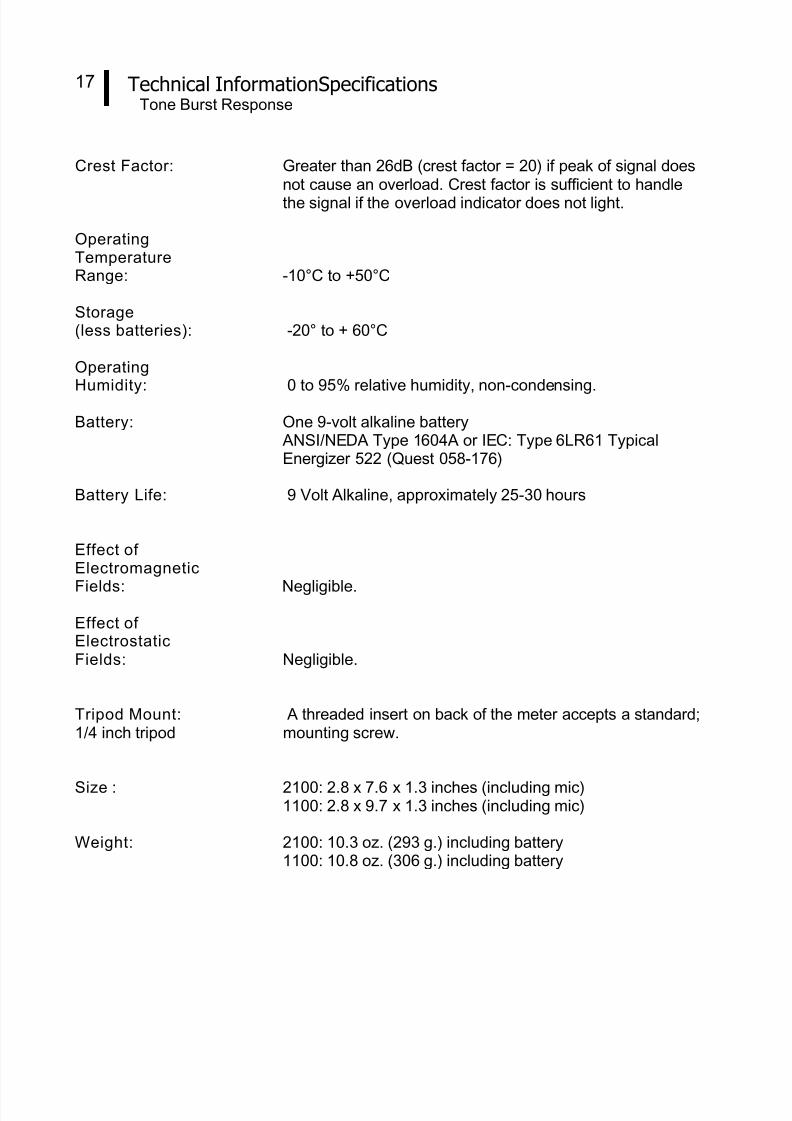
Crest Factor: Greater than 26dB (crest factor = 20) if peak of signal doesnot cause an overload. Crest factor is sufficient to handlethe signal if the overload indicator does not light.
OperatingTemperatureRange: -10°C to +50°C
Storage(less batteries): -20° to + 60°C
Operating
Humidity: 0 to 95% relative humidity, non-condensing.
Battery: One 9-volt alkaline battery ANSI/NEDA Type 1604A or IEC: Type 6LR61 TypicalEnergizer 522 (Quest 058-176)
Battery Life: 9 Volt Alkaline, approximately 25-30 hours
Effect ofElectromagnetic
Fields: Negligible.
Effect ofElectrostaticFields: Negligible.
Tripod Mount: A threaded insert on back of the meter accepts a standard;1/4 inch tripod mounting screw.
Size : 2100: 2.8 x 7.6 x 1.3 inches (including mic)1100: 2.8 x 9.7 x 1.3 inches (including mic)
Weight: 2100: 10.3 oz. (293 g.) including battery1100: 10.8 oz. (306 g.) including battery
8/9/2019 3M Sound Level Meter 1100 en 2100
http://slidepdf.com/reader/full/3m-sound-level-meter-1100-en-2100 22/24
Technical InformationAccessoriesTone Burst Response
056-652, Rev.D 1100/2100 SLM models
18
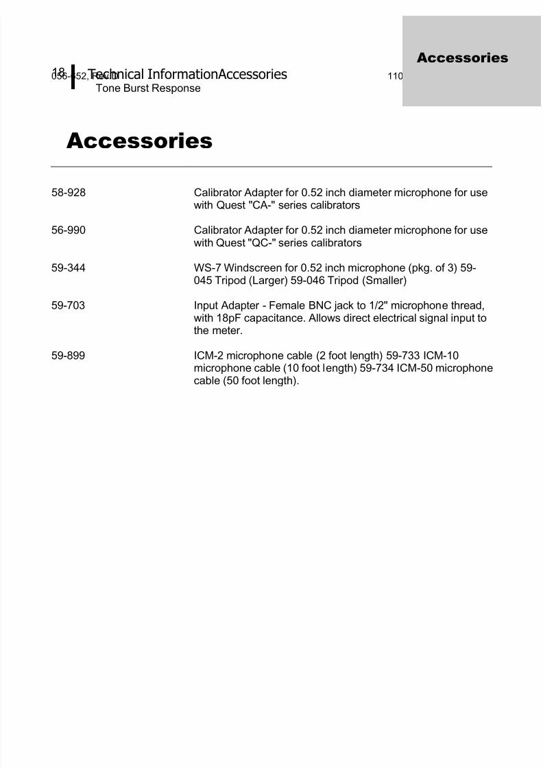
Accessories
58-928 Calibrator Adapter for 0.52 inch diameter microphone for usewith Quest "CA-" series calibrators
56-990 Calibrator Adapter for 0.52 inch diameter microphone for usewith Quest "QC-" series calibrators
59-344 WS-7 Windscreen for 0.52 inch microphone (pkg. of 3) 59-
045 Tripod (Larger) 59-046 Tripod (Smaller)
59-703 Input Adapter - Female BNC jack to 1/2" microphone thread,with 18pF capacitance. Allows direct electrical signal input tothe meter.
59-899 ICM-2 microphone cable (2 foot length) 59-733 ICM-10microphone cable (10 foot length) 59-734 ICM-50 microphonecable (50 foot length).
Accessories

8/9/2019 3M Sound Level Meter 1100 en 2100
http://slidepdf.com/reader/full/3m-sound-level-meter-1100-en-2100 23/24
19 Quest Service Contacting
056-652, Rev.D 1100/2100 SLM models
Quest Service
Contacting Quest Technologies
Should your Quest Technologies equipment need to be returned forrepair or for recalibration, please contact the service department at thefollowing number or access the online form via the website. Fortechnical issues, please contact Technical Support.
Service Department and Technical Support: 1 (800) 245-0779.
Fax: 1 (262) 567-4047. Office hours are 8:00 a.m. to 5:00 p.m. UnitedStates Central.
• E-mail at [email protected]
• Internet at www.quest-technologies.com
International customers
Contact your local, factory-authorized distributor from whom the productwas purchased. You can obtain the name and contact information of
your local factory-authorized distributor from Quest by using the e-mail,telephone, or fax information given under “Contacting QuestTechnologies” above.
Warranty
Quest Technologies warrants our instruments to be free from defects inmaterials and workmanship for one year under normal conditions of useand service. For United States customers, we will replace or repair (ouroption) defective instruments at no charge, excluding batteries, abuse,misuse, alterations, physical damage, or instruments previously repairedby other than Quest Technologies. Microphones, sensors, printers, andchart recorders may have shorter or longer warranty periods. Thiswarranty states our total obligation in place of any other warrantiesexpresses or implied. Our warranty does not include any liability orobligation directly resulting from any defective instrument or product orany associated damages, injuries, or property loss, including loss of useor measurement data.
For warranty outside the United States, a minimum of one year warranty,applies subject to the same limitation and exceptions as above withservice provided or arranged through the authorized Quest distributor orour Quest European Service Laboratory. Foreign purchases shouldcontact the local Quest authorized sales agent for details.
Service &
Warranty

8/9/2019 3M Sound Level Meter 1100 en 2100
http://slidepdf.com/reader/full/3m-sound-level-meter-1100-en-2100 24/24
Quest Technologies, a 3M company, is a world class manufacturer and leader in the eld
of occupational safety, industrial hygiene and environmental instrumentation. Quest prod-
ucts are used in more than 80 countries worldwide. Quest has a strong reputation of rugged,
reliable instrumentation and software systems that monitor and evaluate occupational and
environmental health and safety hazards including noise, vibration, heat stress, indoor air
quality and toxic/combustible gases.
Quest monitoring instruments serve a variety of occupations and industries with clients in
mining, research, enforcement, military, education, insurance and manufacturing business
sectors.
• Visit www.questtechnologies.com for further information.
Occupational Health &Environmental Safety DivisionQuest Technologies, a 3M CompanyISO 9001 Registered CompanyISO 17025 Accredited Calibration Lab1060 Corporate Center DriveOconomowoc, WI 53066Customer Service: 262-567-9157Toll Free: 800-245-0779
www.questtechnologies.com
Please recycle. Printed in USA.© 2011 3M All rights reserved.056-652, Rev.D 1/11