3M Dynatel Cable/Pipe/Fault Advanced Locator - PMC … · 3M™ Dynatel™ Cable/Pipe/Fault...
52
3M ™ Dynatel ™ Cable/Pipe/Fault Advanced Locator 2250ME/2273ME Series (With 3-watt, 5-watt, or 12-watt Transmitter) Operator’s Manual 2250ME 2250ME-iD 2273ME 2273ME-iD February 2009 78-8130-6151-8-E 3
Transcript of 3M Dynatel Cable/Pipe/Fault Advanced Locator - PMC … · 3M™ Dynatel™ Cable/Pipe/Fault...

3M™ Dynatel™ Cable/Pipe/Fault Advanced Locator 2250ME/2273ME Series(With 3-watt, 5-watt, or 12-watt Transmitter)
Operator’s Manual
2250ME 2250ME-iD 2273ME 2273ME-iD
February 200978-8130-6151-8-E 3

2 78-8130-6151-8-E
ContentsSafety Information ................................................................................................ 4
About This Manual ............................................................................................... 4
Quick Start ............................................................................................................ 5
Menu Screens ...................................................................................................... 10
Configuring The Receiver ................................................................................... 12
Buried Cables And Pipes .................................................................................... 15
Receiver Modes ................................................................................................... 18
Depth and Current Estimate ................................................................................ 20
Frequencies ......................................................................................................... 21
Locating in Directional Peak Mode .................................................................... 22
Locating Active Duct Probes (Sondes) ............................................................... 25
Buried Sheath Faults And Earth/Return Faults ................................................... 26
3M™ Electronic Markers and 3M™ EMS iD Markers ......................................... 28
Locating 3M™ EMS Markers .............................................................................. 29
Marker Depth Estimate ....................................................................................... 31
Creating/Editing Templates for 3M™ EMS iD Markers ...................................... 33
Writing iD Markers ............................................................................................. 36
Modifying Marker Data to be Programmed ........................................................ 37
Reading iD Markers ............................................................................................ 38
GPS Operation .................................................................................................... 39
Reviewing Marker History .................................................................................. 43
Other Applications .............................................................................................. 44
Cable Identification ............................................................................................. 45
Help Mode .......................................................................................................... 46
3M™ Dynatel™ PC Tool Kit ................................................................................. 46
Self Test Of Receiver .......................................................................................... 47
Product Description And Optional Accessories .................................................. 47
Receiver Specifications ....................................................................................... 49

78-8130-6151-8-E 3
Congratulations! You have just purchased one of the finest, most advanced locating devices available today!
The 3M™ Dynatel™ Cable/Pipe/Fault Locators 2250ME-iD/2273ME-iD are designed with all of the functionality of previous Dynatel models, and iD versions have the enhanced capability to read and write user information into the 3M EMS iD markers. Information such as a pre-programmed identification number, facility data, application type, placement date and other details can all be read, stored and downloaded to your PC for enhanced resource management with this revolutionary equipment. The Dynatel Cable/Pipe/Fault Locators 2250ME-iD/2273ME-iD will also search for two different types of utility markers simultaneously. When used in conjunction with a hand-held GPS the ability to transmit path and marker coordinates multiplies the potential to the mapping industry. This equipment provides a simple system for mapping utility information directly into CAD and GIS systems.
3M is dedicated to bringing you premium equipment with outstanding reliability, backed by one of the best warranties in the business and outstanding service.
Visit our website at http://www.3M.com/dynatel for more application notes.
4 78-8130-6151-8-E
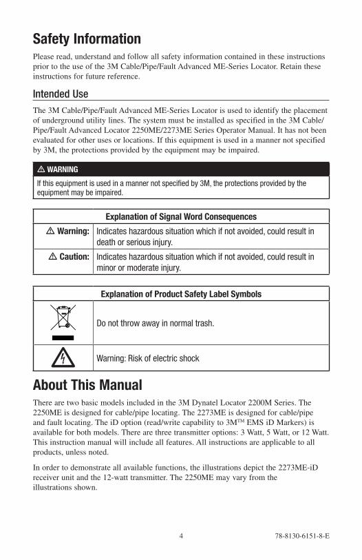
Safety InformationPlease read, understand and follow all safety information contained in these instructions prior to the use of the 3M Cable/Pipe/Fault Advanced ME-Series Locator. Retain these instructions for future reference.
Intended UseThe 3M Cable/Pipe/Fault Advanced ME-Series Locator is used to identify the placement of underground utility lines. The system must be installed as specified in the 3M Cable/Pipe/Fault Advanced Locator 2250ME/2273ME Series Operator Manual. It has not been evaluated for other uses or locations. If this equipment is used in a manner not specified by 3M, the protections provided by the equipment may be impaired.
m WARNING
If this equipment is used in a manner not specified by 3M, the protections provided by the equipment may be impaired.
Explanation of Signal Word Consequences
m Warning: Indicates hazardous situation which if not avoided, could result in death or serious injury.
m Caution: Indicates hazardous situation which if not avoided, could result in minor or moderate injury.
Explanation of Product Safety Label Symbols
Do not throw away in normal trash.
c Warning: Risk of electric shock
About This ManualThere are two basic models included in the 3M Dynatel Locator 2200M Series. The 2250ME is designed for cable/pipe locating. The 2273ME is designed for cable/pipe and fault locating. The iD option (read/write capability to 3MTM EMS iD Markers) is available for both models. There are three transmitter options: 3 Watt, 5 Watt, or 12 Watt. This instruction manual will include all features. All instructions are applicable to all products, unless noted.
In order to demonstrate all available functions, the illustrations depict the 2273ME-iD receiver unit and the 12-watt transmitter. The 2250ME may vary from the illustrations shown.

78-8130-6151-8-E 5
Quick StartTransmitter Battery InstallationLoosen the six screws on the battery compartment cover on the bottom of the transmitter. Remove the cover.
Install six ‘C’ cell batteries (LR14) into the compartment as indicated by the polarity symbols (+ and –).
Replace the cover and tighten the screws.
Press and hold OFF [T-1] to manually test the batteries. The display and audio will indicate one of the following levels: (OK w/solid tone = good; LO w/beeping tone = low; "--" w/no tone = replace)
m CautionTo reduce the risks associated with fire and explosion:• Do not short, excessively heat, or dispose of batteries in fire.• Install batteries with proper polarity.• Use only Alkaline "C" (LR14) sized batteries.• Do not charge batteries• Do not use leaking batteries
To reduce the risks associated with environmental contamination:• Dispose of batteries and electronic components in accordance with all regulations.• Ensure batteries are installed with correct polarity.• Always remove batteries when storing the units for long periods of time.

6 78-8130-6151-8-E
Receiver Battery InstallationRemove cap from receiver handle.
Install eight ‘AA’ cell batteries (LR6) into the battery holder as indicated by the polarity symbols (+ and –).
Attach battery holder to the PP3 connector in the receiver handle, and slide holder into the handle. Replace the cap.
8 “AA” Alkaline Batteries
1. Twist cap to open battery compartment.
2. Slide battery compartment out of handle.
m CautionTo reduce the risks associated with fi re and explosion:• Do not short, excessively heat, or dispose of batteries in fi re.• Install batteries with proper polarity.• Use only Alkaline "AA" (LR 6) sized batteries.• Do not charge batteries• Do not use leaking batteries
To reduce the risks associated with environmental contamination:• Dispose of batteries and electronic components in accordance with all regulations.• Ensure batteries are installed with correct polarity.• Always remove batteries when storing the units for long periods of time.
The receiver batteries are tested for two seconds every time the unit is turned on.
The bar graph on the screen will fill to the relative battery level.
The Battery Icon [8] on the Locate Screen will continuously indicate the battery level.
CleaningTo clean the unit, wipe with a damp cloth.

78-8130-6151-8-E 7
Service and AccessoriesInformation regarding service, accessories, or replacement parts can be obtained by contacting your local 3M Sales Office or 3M Sales Representative.
This equipment does not require annual calibration or maintenance.
Transmitter Keypad and Connector Definitions
T-1 T-2 T-3 T-4 T-5 T-6 T-7
OFF: [T-1] Turns unit off and performs battery test.
OHM / FAULT / TONE: [T-2] Turns the unit on and cycles through the following commands when pressed repeatedly.
OHM METER: Measures the continuity of the trace conductor/pipe and its far-end ground. It is also used to measure the fault resistance to earth.
FAULT LOCATE: (2273ME units only) In this mode, the transmitter sends two alternating frequencies (577 Hz and 33 KHz) as well as fault signals 10 and 20 Hz.
TONE: In the tone mode, the transmitter generates 577 Hz and 133 KHz signals.
TRACE: [T-3] Turns the unit on and places the unit in Trace mode.
SELECT FREQUENCY: Press TRACE [T-3] repeatedly to cycle the frequency of the transmitter (577 Hz, 8 KHz, 33 KHz, and 133 KHz). The selected frequency will be displayed [T-4]. ‘ALL' indicates that multiple frequencies are transmitting simultaneously.
DISPLAY: [T-4]
INDICATOR FLAGS: These flags coincide with the operational mode of the transmitter. (From top left to bottom right) Fault mode [T-2] (2273ME units only), Tone [T-2], Trace mode [T-3], Ohm meter [T-2], Voltage (at start up the transmitter checks for foreign voltage), and the Output Flag (no flag = low output; flag = high output; flashing flag = maximum output).
DIGITAL DISPLAY: Indicates frequency, relative current, resistance, battery level and voltage.
OUTPUT: [T-5] Cycles output level; normal, high and maximum.
Normal=No Flag; High=Flag; Maximum=Flashing Flag
OUTPUT JACK: [T-6] Port for direct connect cables or Dyna-coupler.
EXTERNAL JACK: [T-7] Port to connect cigarette lighter adapter cable, or rechargeable battery (2200RB). Input voltage level: 9-18 VDC.

8 78-8130-6151-8-E
Maximum Transmitter OutputAn external 12V DC source is required for 12-Watt Output. Connecting the rechargeable battery (2200RB) to the external jack [T-7] will provide this external source, or the cigarette lighter adapter cable (included with high powered units) can be used to connect the DC power from a vehicle’s battery source to the transmitter’s external jack T-7.
Press Output [T-5] twice for maximum output mode.
The indicator flag will flash when the transmitter is in max output mode.
Note: The external DC source does not charge the internal batteries.
m WARNING
To reduce the risk associated with hazardous voltage:• Potential for electric shock exists when handling connection cables while the transmitter is
ON. Make all connections prior to powering on the unit. Turn transmitter OFF before handling connection cables.
• Voltage greater than 240 volts will damage equipment and could cause personal injury or death. Make all connections before turning on the transmitter. Follow standard procedures for reducing the voltage.
• Do not change or modify this product in any way.
Rechargeable BatteryThe 3M Dynatel Sealed Gel-Cell Battery 2200RB can be used as an auxiliary battery in 3M™ Dynatel™ 2200 Series Transmitters. It plugs into the external jack [T-7] and provides power for the transmitter. When the rechargeable battery is plugged in, normal output, high output, and maximum output is available. When the rechargeable battery is connected to the transmitter, the alkaline batteries are bypassed. The rechargeable battery is a lead acid battery rated at 5.4 amp-hours and is equipped with a user replaceable fuse (5A/32V).
Note: The internal batteries must be at least 5.4 volts. Do not remove the alkaline batteries from the transmitter when using the rechargeable battery.

78-8130-6151-8-E 9
Receiver Key Pad Definitions
POWER: [1] Turns unit off and on.
SPEAKER: [2] Adjusts the volume of the receiver (off, low, med, high, and Xpand).
SPEAKER ICON [2A]: Indicates the relative volume level of the receiver. When the third ring is dotted and ‘xpnd' appears below the speaker icon, the receiver is in “Expander” mode. This mode is used to pinpoint the target cable or pipe.
CONTRAST: [3] The arrows located above and below the contrast icon will adjust the contrast of the screen.
GAIN: [4] Adjusts the sensitivity of the receiver either up or down to maintain a satisfactory signal level.
LOCATE/OK: [5] Sets the receiver to trace mode for locating cable or pipe. Acknowledges setup entries (OK).
MENU: [6] Displays setup screen for configuration of the unit, i.e.: clock, language, depth units, marker data and frequencies.
BACKLIGHT: [7] Toggles the backlight low, high, and off.
BATTERY ICON: [8] Indicates battery level.
SOFT KEY: [SK] There are four soft keys on the receiver. The function of each key is shown above the key on the display screen. The functions will change, depending on the operation mode of the receiver. For instruction purposes, the display command is followed by [SK] to identify it as a soft key.
SOFT KEY COMMAND: [9] Definitions for each of the four soft key functions.
SIGNAL STRENGTH: [10] Digital reading of the signal the receiver is detecting.
BAR GRAPH: [11] Graphical representation of the received signal.
GAIN LEVEL: [12] Displays relative gain level.
EXTERNAL JACK: [l3] Port to connect cables from external devices such as the earth frame, a second Dyna-Coupler, or toning coil.
SERIAL PORT: [14] RS232 port to connect the receiver to a PC via straight serial cable (not included).
EARPHONE JACK: [15] Will fit standard 1/8 inch mini-jack mono earphone plug (not included).

10 78-8130-6151-8-E
Menu ScreensMain MenuWhen the Menu [6] button is pressed, the Main Menu screen appears.
The function appears on the screen above each soft key.
1. Write Mode: System used to write information to RFiD Markers
2. Data/Template: Displays marker history and template creation/selection screens:
a. Read History – 100 memory locations for Read RFiD Markers
b. Write History – 100 memory locations for Programmed RFiD Markers
c. User Templates – Create and edit RFiD templates for RFiD Markers (max =32)
d. Trace Templates – Create and edit templates used to identify path (max = 5)
3. COM Setup: Displays second level COM Port setting screen to configure RS232 port communication with different devices –
a. PC – Receiver will communicate to a computer
b. NMEA – Port is configured to accept coordinates from GPS
c. GIS – Port is configured to send RFiD information or path information to GPS device and receive coordinates from GPS.
d. PDA – receiver will send RFiD and path information in ASCII string.
4. More>>: Advances to next menu screen
78-8130-6151-8-E 11
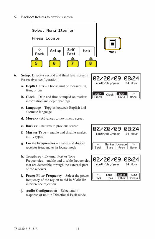
5. Back<<: Returns to previous screen
6. Setup: Displays second and third level screens for receiver configuration
a. Depth Units – Choose unit of measure; in, ft-in, or cm
b. Clock – Date and time stamped on marker information and depth readings.
c. Language – Toggles between English and alternate language
d. More>> - Advances to next menu screen
e. Back<< - Returns to previous screen
f. Marker Type – enable and disable marker utility types
g. Locate Frequencies – enable and disable receiver frequencies in locate mode
h. Tone/Freq - External Port or Tone Frequencies – enable and disable frequencies that are detectable through the external port of the receiver
i. Power Filter Frequency – Select the power frequency of the region to aid in 50/60 Hz interference rejection
j. Audio Configuration – Select audio response of unit in Directional Peak mode

12 78-8130-6151-8-E
7. Self Test: Displays information about unit and performs a self check test
8. Help: Offers the user on-screen instructions
Configuring The ReceiverIn the setup mode, the units of depth measurement, time, date, and date format can be set. The receiver can be configured to detect only certain frequencies and/or specific utility markers. User defined frequencies can be programmed, language of the receiver can be selected, and tone frequencies set.
Select Depth UnitsMENU [6] + More>>[SK] + Setup [SK] + Units [SKToggle]
• Press Units [SK toggle].
• The soft key command will toggle between inches (in), centimeters (cm), and feet/inches (ft-in).
Setting the Receiver ClockSet the time, date, and date format of the receiver. Depth and Current measurements are time and date stamped, as well as read write marker information (iD units only).
MENU [6] + More>>[SK] + Setup [SK] +Clock [SK]
• Press the left/right arrow [SK] to highlight the digit of the date or time to change.
• Press the + or - [SK] to increment or decrement.
• When the date format is highlighted, the format will toggle between mm/dd/yy and dd/mm/yy.
• Press OK [SK] to save, or Menu [6] to cancel.
Selecting a LanguageMENU [6] + More>>[SK] + Setup [SK] + Lang [SKToggle]
The soft key command will cycle through available languages. Alternate languages can be uploaded to the receiver using the Dynatel™ PCTools software. (Available for download at www.3M.com/dynatel.)

78-8130-6151-8-E 13
Enabling/Disabling FrequenciesMENU [6] + More>>[SK] + Setup [SK] + + More» [SK] + Locate Freq [SK]
The user can select the frequencies that the receiver will detect. All the available frequencies are listed in four groups (Left to Right: Active, Power, Passive, and Auxiliary). The Auxiliary group also contains the User Defined Frequencies. (See Creating User Defined Frequencies.)
1. Press the right arrow [SK] to move the highlight bar to the section of frequencies to enable, or disable.
2. Press the up/down arrows [SK] to highlight the specific frequency.
3. Press Enabl/Disabl [SK]. (Enable denoted by 3)
4. Repeat steps 2 & 3 to enable/disable other frequencies.
5. Press OK [5] to save.
Selecting External Jack Frequencies (Tone Frequencies)MENU [6] + More>>[SK] + Setup [SK] + + More» [SK] + Tone Freq [SK]
A coupler can be plugged into the external jack of the receiver and used to identify cables. (See Other Applications: Cable Identification.) The same procedure as above is followed for selecting frequencies that can be detected by the external jack found on the bottom of the receiver.
Creating User Defined FrequenciesMENU [6] + More>>[SK] + Setup [SK] + + More» [SK] + Locate Freq [SK]
There are four user defined frequencies available on the receiver. (These frequencies must be between 50 Hz and 999 Hz.) These frequencies are found in the column on the far right of the Locate Freq screen (Auxiliary frequencies). These frequencies, once programmed, will appear in the Locate mode under the Aux [SK] frequency list.
To program the user defined frequencies press the right arrow [SK] to highlight the Auxiliary group of frequencies. Press the up/down arrows [SK] to highlight the user frequency to program. Press Enabl/Disabl [SK].

14 78-8130-6151-8-E
Press the left/right arrows [SK] to move the square cursor to a digit. Press Select [SK] to enter the number in the frequency field.
Press OK [5] to save the programmed frequency, or press Exit [SK] to cancel. The frequency will appear in the locate frequency screen as U ###.
Note: To redefine a previously programmed user frequency, highlight the frequency, press enabl/disabl, select the back arrow with the cursor, and press select to delete the previous entry.
Filtering Power Frequency InterferenceMENU [6] + More>>[SK] + Setup [SK] + + More» [SK] + More>>[SK] + Filter [SK]
In order to filter out unwanted power influences while locating with user-defined frequencies, verify the correct frequency is selected for your location (default 50 Hz).
Selecting Locating AudioMENU [6] + More>>[SK] + Setup [SK] + + More» [SK] + More>>SK + Audio Config [SK]
The user can choose the audio response of the receiver when using the Directional Peak mode for path locating. Highlight the audio selection and press OK to save.

78-8130-6151-8-E 15
Buried Cables And PipesTransmitter ConnectionsPerform a battery test. Use one of the following three methods to produce a trace signal on the target pipe or cable.
Direct Connect MethodPlug the direct connect cable into the output jack [T-6] of the transmitter. Connect the black clip to the ground rod. Place the ground rod in the earth perpendicular to the suspected cable/pipe path. If necessary, extend the black lead with the Ground Extension Cable (#9043 available separately).
1. Remove the ground bonding and attach the red clip to the shield of the cable, pipe, or target conductor. (If locating power cables, the red clip can be attached to the transformer cabinet, or the meter box).
2. Turn the transmitter on by pressing Ohms [T-2]. The continuity of the circuit will be measured. The results are displayed [T-4] in ohms and as a tone.
− If the continuity of the circuit is very good (the reading on the display is less than 3K Ω. and a solid tone from the transmitter is heard) all frequencies can be used to locate. Always use the lowest frequency available. Lower frequencies are less likely to ‘bleed over’ to other cables in the same area, and are very good for tracing over long distances.
− If the circuit reads more than 3K Ω., but less than lOK Ω (indicated by a beeping tone from the transmitter) it will be necessary to use a higher frequency than 512 Hz or 577 Hz in order to locate the cable/pipe.
− If the circuit reads more than lOK Ω., it will be necessary to use an RF signal such as 33 KHz or 133 KHz.
− If there is no tone and the transmitter indicates that there is an open circuit (OL in the display) this could be an indication of a poor ground, or an open-ended cable or pipe. Use one of the higher frequencies available, at high level. If it is an open-ended cable or pipe, the receiver's response will decrease suddenly at the site of the clear or severed end.

16 78-8130-6151-8-E
Note: In the ohms mode, the transmitter can detect voltage as well as ohms. If a low voltage is detected, the display will alternate between displaying ohms and volts. When displaying ohms, the flag over the Ω symbol will be visible. When displaying volts, the flag over the ‘V' will be visible. When the voltage magnitude is sufficient to impair the accuracy of the ohms measurement, only voltage will be displayed. If the voltage is AC, a sine wave will be visible on the display [T--4]. If a high AC voltage is detected, a rapid beeping tone will be heard.
3. Press the Trace [T-3] repeatedly until the desired frequency appears on the display.
4. Press Output [T-5] to select high output level for longer tracing distances or deep pipe/cable.
Dyna-Coupler Method
1. Connect the Dyna-Coupler to the transmitter output jack [T-6] using the coupler cable (9011).
2. Clamp the Dyna-Coupler around the cable or pipe, below any bonds, just before it enters the earth. The jaws of the coupler must fully close.
3. Press Trace [T-3] to turn on the transmitter. Press again to select 8 KHz, 33 KHz or 133 KHz.
Note: When using a Dyna-Coupler, always select high output level by pressing the output key [T-5] on the transmitter.

78-8130-6151-8-E 17
Induction Method
If you cannot make a direct connection, or use the 3M™
Dynatel™
Dyna-Coupler clamp to apply a locating signal on the target, use the induction method. This method uses the internal coil of the transmitter to generate a magnetic field. This is the least preferred method of applying a signal on a target conductor because it can easily be picked up by other non-target conductors in the area. However, it is the preferred method of applying a signal to multiple cables/pipes in the same trench, and for the ‘two-man sweeping’ application.
1. Verify battery level of transmitter and remove any cables from the output jack.
2. Position the transmitter over the target facility with the hinge of the transmitter over and in line with the cable/pipe path.
3. Align the Induction Direction arrows on the transmitter with the target conductor.
4. Turn on the transmitter by pressing the Trace [T-3] key.
5. Press Trace [T-3] again to select 33 KHz or 133 KHz.
6. Select High Output level for the best signal-to-noise ratio.
7. Trace the signal path with the receiver using the Induction Peak mode.
The induction mode of the receiver is a mode in which the upper antenna of the receiver is tuned to minimize distortion from the magnetic field of the transmitter.
Note: The receiver must be at least 25 feet away from the transmitter to begin tracing the target path.

18 78-8130-6151-8-E
Receiver Modes
Directional PeakMODE + Directional Peak (DirPk) [SK Toggle]
In DirPk mode, four peak antennas are used to analyze the magnetic field pattern. The bar graph indicates signal strength and the directional arrows sense the edges of the magnetic field. The left/right arrows will indicate the direction to the nearest cable that is in-line with the receiver handle.
As the antenna crosses the cable or pipe, the receiver speaker volume increases to a maximum, the bar graph [1l] fills from both sides toward the middle, and the numeric signal strength [10] increases. As the antenna moves off the target path, the speaker volume decreases and the bar graph opens. Use the bar graph and the numeric signal indicator to locate the exact target path.
Left of Target Path Directly Over Target Path Right of Target Path
Once the target path has been located, the arrows at the top of the screen will indicate the location of the target path in relationship to the receiver.
Note: When field distortion (due to congestion) is affecting the receiver the left/right arrows may not coincide with the bar graph. Use the maximum numerical signal strength to target the cable or pipe.
Directional Null MODE + (DirNull) [SK Toggle]
In DirNull mode, as the operator approaches the cable or pipe, the numerical signal will increase then fall sharply as the receiver crosses the target cable or pipe. The bar graph fills from both sides toward the middle and the receiver speaker volume decreases. As the antenna moves off the target path, the bar graph opens, the signal strength increases, and the speaker volume increases. Gain adjust is automatic in DirNull mode.
The center of the DirNull screen provides a ‘compass view' of the target path. An arrow will point toward the location of the cable/pipe in 45-degree steps. A solid line will appear over the cable/pipe, indicating its orientation to the receiver handle.

78-8130-6151-8-E 19
For example:
Figure 1: If the target path is to the right of the receiver, and running parallel to the operator, the right arrow will display.
Figure 2: If the target path is to the left and in front of the operator (not running parallel to the receiver) the arrow will point toward the top left side of the screen.
Figure 3: When the receiver crosses the target path, a solid line will appear, instead of arrows, indicating the target path and its orientation to the receiver.
Before marking target path, always use directional peak or special peak mode to verify location.
Special PeakMODE + (Spl Pk) [SK Toggle]
Special Peak Mode turns on only the peak antenna closest to the ground. Special Peak Mode is used in applications such as very deep cable, or when the signal is too weak for normal or directional peak tracing.
Inductive Peak (IndPk)MODE + IndPk [SK Toggle]
If you cannot make a direct connection, or use the 3M™
Dynatel™
Dyna-Coupler clamp to apply a locating signal on the target, use the induction method. This method uses the internal coil of the transmitter to generate a magnetic field.
The induction mode of the receiver is a mode in which the upper antenna of the receiver is tuned to minimize distortion from the magnetic field of the transmitter.

20 78-8130-6151-8-E
Expanded ModeWhen the third ring of the speaker icon is dotted or broken and ‘xpnd’ appears below the speaker icon, the receiver is in “Expanded” mode. This mode is used for pinpointing a target cable or pipe. The area of response of the receiver narrows, allowing the locator to detect very small signal changes.
Depth and Current EstimateVerifying the target path, depth and current can be helpful tools.
1. Pinpoint the cable or pipe being located.
2. Lower the tip of the receiver to the ground and press Depth [SK].
− The depth to the target cable or pipe is displayed in the units specified in the receiver set up menu. The bold current reading is a relative current measurement. This reading can be compared to the current reading that alternately flashes with the frequency on the transmitter. The milliamp reading is an actual current measurement.
− There are two options for measuring depth. Live depth is a continuous measurement. 1-Shot Depth is an averaging of the depth reading. When in 1-Shot mode, the unit will average the depth reading for three seconds, and then display the result on the screen. Press Depth [SK] to alternate between the two modes.
− Five depth readings can be saved with the time, date and relative current measurements.
3. Pressing Save [SK] will place each entry in sequential order in memory (M1 - M5) until five readings have been stored. The unit will overwrite saved entries in excess of five, beginning with M1.

78-8130-6151-8-E 21
4. Press Clear All [SK] to delete all stored depth information.
− The operator may select the memory location to store the depth readings by pressing Mem Select [SK]. When the preferred location appears on the screen, press Save [SK]. The screen and memory location will populate with the current information.
− Each memory location can be reviewed by pressing Mem Select [SK].
5. Press Locate [5] to return to Locate Mode.
FrequenciesActiveActive frequencies are trace signals supplied by a 3M™ Dynatel™ Transmitter 2200 Series (577 Hz, 8 KHz, 33 KHz, or 133 KHz).
1. Select the same frequency that the transmitter is generating;
2. Press Locate [5]
3. Press Cable/Pipe [SK]
4. Press Freq [SK]
5. Press ACTIVE [SK Toggle] until the desired frequency is displayed in the soft key command [9] (“Active” 577, 8K, 33K or 133K)
6. Press Locate [5] to return to Locate mode.
PowerPower frequencies refer to 50 or 60 Hz signals, and their harmonics that can be traced without the use of a transmitter.
50: Best for general locating of passive power.
50H (high harmonic): If the 50 choice appears to be responding slowly, or poorly, then 50H is the second choice for locating of passive power.
50L (low harmonic): Third choice for passive power locating. May be used when 50 or 50L is weak or erratic.
100 Hz: Used for locating rectified AC power signals, often found on pipelines using impressed current cathodic protection.
1. Press Locate [5]
2. Press Cable/Pipe [SK]
3. Press Freq [SK]
22 78-8130-6151-8-E
4. Press Power [SK Toggle] until the desired frequency is displayed in the soft key command [9] (“Power” 50, 50L, 50H, or 100).
5. Press Locate [5] to return to Locate mode.
All export receivers default to 50 Hz.
To set the receiver to detect 60 Hz signals refer to Enabling/Disabling Frequencies section of this manual.
PassiveThe receiver (without a 3M Dynatel Transmitter 2200) can be used to detect some CATV cables (31.5 KHz). (A horizontal-scan television NTSC must be turned on to generate this frequency.)
1. Press Locate [5]
2. Press Cable/Pipe [SK]
3. Press Freq [SK]
4. Press Pasv [SK Toggle]
5. Press Locate [5] to return to Locate mode.
AuxiliaryAuxiliary frequencies are signals generated from remote location transmitters, or frequency generating transmitters.
1. Press Locate [5]
2. Press Cable/Pipe [SK]
3. Press Freq [SK]
4. Press Aux [SK Toggle] until the desired frequency is displayed in the softkey command [9] (“Aux” 512, 560, 333 Hz, or user defined frequencies).
5. Press Locate [5] to return to Locate mode.
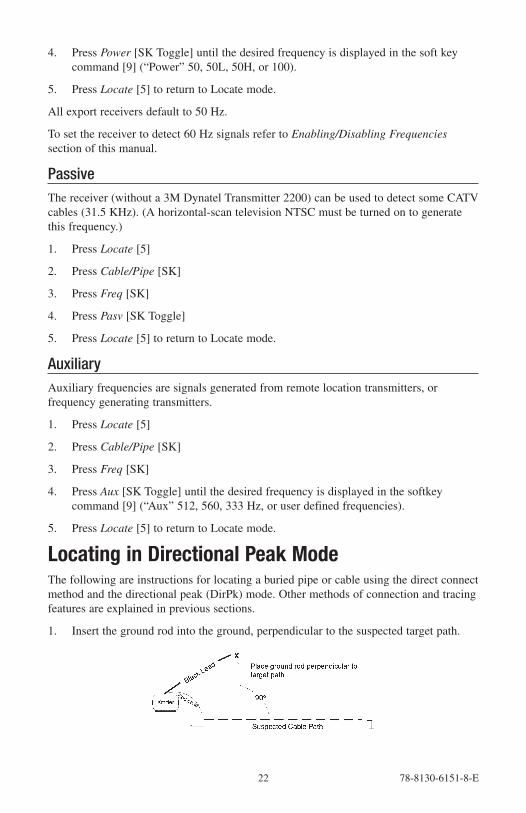
Locating in Directional Peak ModeThe following are instructions for locating a buried pipe or cable using the direct connect method and the directional peak (DirPk) mode. Other methods of connection and tracing features are explained in previous sections.
1. Insert the ground rod into the ground, perpendicular to the suspected target path.

78-8130-6151-8-E 23
2. Remove the grounding from the near-end of the target cable/pipe.
Note: Never connect, or disconnect the transmitter when the unit is on.
3. Connect the red lead of the transmitter to the shield, neutral, or deenergized target conductor.
4. Connect the black lead of the transmitter to the ground rod.
5. Perform a battery check by pressing and holding OFF [T-1].
6. Turn the power on the transmitter by pressing OHMS [T-2].
a. A solid tone from the transmitter indicates a complete circuit with a good ground.
b. A beeping tone from the transmitter indicates a usable ground. An attempt should be made to improve the ground.
c. No tone from the transmitter indicates a poor, or no ground. The transmitter will display ‘OL’ in this instance. An attempt should be made to improve the ground. Verify that the far end is grounded.
7. Press TRACE [T-3] to set the transmitter to Trace mode.
8. Select a frequency on the transmitter by pressing TRACE [T-3]. The unit will cycle through the available frequencies (577, 8K, 33K, 133K, and ALL).
9. Press Power [1] to turn on the receiver.
10. Press Locate [5].
11. Press Cable/Pipe [SK].
12. Set the Frequency and mode of the receiver.
a. Press Freq [SK]
b. Select the same frequency on the receiver as the transmitter by pressing Active [SK Toggle].
c. Press Locate [5] to save the setting and return to locate mode.
d. Press Mode [SK Toggle] until DirPk is displayed.
13. Stand away from the suspected target path and adjust the Gain Down [4] until the bar graph opens completely.
14. Walk in a wide circle with your back toward the transmitter (about 3 to 4.5 meters away).
− Watch the receiver screen and listen to the signal. Take note of where the receiver detects the strongest signals.
− The bar graph will close when the unit detects a signal, and the arrows will reverse.

24 78-8130-6151-8-E
− Adjust the Gain Down [4] if the bar graph closes completely.
− The numbers on the display will change with the signal strength (smaller, as you walk away from the target path; larger, as you approach the target path).
− Make a complete circle around the transmitter. Return to each point in the circle that the receiver detected.
15. Measure the depth and current of each to identify the target path. The depth of the target path should be as expected and the relative current should compare to the relative current of the transmitter.
Note: The current reading will decrease steadily as the locator moves away from the transmitter. When using higher frequencies, this decline is more evident.
16. Adjust the gain so that the bar graph responds to the target path (open when off path, almost completely closed when directly over target).
17. Trace the cable/pipe at a slow walk while moving the receiver in a side-to-side motion, keeping the receiver perpendicular to the ground.
18. Measure the depth and current occasionally to verify target path.
Note: In order to measure the depth and current accurately, the operator must pinpoint the target pipe or cable, and the receiver handle should be in-line with the target path.
− While in DirPk mode, find the highest signal strength [10].
− Lower the tip of the receiver to the ground. Twist the receiver left and right while watching the signal strength.
− When the highest reading is displayed, the handle of the unit is in line with the target pipe or cable.
Occasionally, signal will appear on adjacent cables or pipes. Compare the relative and actual current readings over each path to help determine the target path. Current readings will be significantly less on the adjacent cable compared to the target path.
19. As tracing proceeds, remember that the most powerful signal is near the transmitter. As the receiver gets farther away from the transmitter the signal strength [10] decreases. It may be necessary to readjust the gain as needed; to be sure there is adequate signal for the receiver to operate. Press the Gain up/down [4] when the bar graph is no longer visible (too little signal) or when the bar graph is closed (too much signal).
20. Trace the path until you reach a logical termination point (i.e.: terminal, meter, cabinet, etc).

78-8130-6151-8-E 25
Locating Active Duct Probes (Sondes)1. Turn the Receiver on [1].
2. Press Locate [5]
3. Press Cable/Pipe [SK].
4. Press Mode [SK Toggle] to select Special Peak (SplPk).
5. Press Freq [SK]
6. Press Active [SK Toggle] to select the 33kHz frequency (for a 33 KHz Sonde or ADP)
7. Press Locate [5].
8. With the receiver handle perpendicular to the conduit path, locate the ADP position by moving along the path until the strongest signal is found. Adjust Gain Up/Down [4] when the bar graph remains either fully open or fully closed.
9. Refer to the ADP operating instructions for further information.
Determining ADP Depth1. Place the tip of the receiver on the ground directly above the located ADP position.
2. Maintain the handle orientation perpendicular to the target path.
3. Press Depth [SK] in the Locate Screen.
4. Press Sonde Depth [SK] to read ADP Depth
− The depth to the ADP is displayed in units, as specified in the receiver set up menu.
− Five Sonde depth readings can be saved with the time, and date measured.
− Save [SK] will place each entry in sequential order in memory (M1 - M5) until five readings have been stored. The unit will overwrite saved entries in excess of five, beginning with M1.
5. Press Clear All [SK] to delete all saved depth readings.
6. Press Mem Select [SK] to select the memory location to store the depth readings.
7. When the preferred location appears on the screen, press Save [SK]. The screen and memory location will populate with the current information.
8. Each memory location can be reviewed by pressing Mem Select [SK].
9. Press Cable Depth [SK] to switch to the cable depth screen, or Locate [5] to return to Locate Mode.
Note: During a depth measurement, the display will exhibit ‘- -’ when the received signal is too low, too high or erratic.
26 78-8130-6151-8-E
Buried Sheath Faults And Earth/Return FaultsNote: Remove both the near-end and far-end grounding from the test section.
Transmitter SetupNote: Do not make any connections while the transmitter is on.
1. Attach the red clip to the earth-faulted conductor of the cable or conductor under test.
2. Place the ground rod behind the transmitter and in parallel with the target path.
3. Connect the black clip to the ground rod behind the transmitter and in parallel with the target path.
4. Press and hold OFF [T-1] to perform a battery test.
5. Press OHMS/FAULT/TONE [T-2] to turn the transmitter on.
− The resistance of the fault will be displayed in ohms on the transmitter display [T-4].
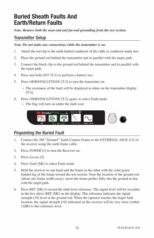
6. Press OHMS/FAULT/TONE [T-2] again, to select Fault mode.
− The flag will turn on under the fault icon.
Pinpointing the Buried Fault1. Connect the 3M™ Dynatel™ Earth Contact Frame to the EXTERNAL JACK [13] of
the receiver using the earth frame cable.
2. Press POWER [1] to turn the Receiver on.
3. Press Locate [5].
4. Press Fault [SK] to select Fault mode.
5. Hold the receiver in one hand and the frame in the other with the solid green-banded leg of the frame toward the test section. Near the location of the ground rod (about one frame width away), insert the frame probes fully into the ground in line with the target path.
6. Press REF [SK] to record the fault level reference. The signal level will be recorded in the box above REF [SK] on the display. This reference indicates the signal strength [10] level at the ground rod. When the operator reaches the major fault location, the signal strength [10] indicated on the receiver will be very close (within 12dB) to this reference level.
78-8130-6151-8-E 27
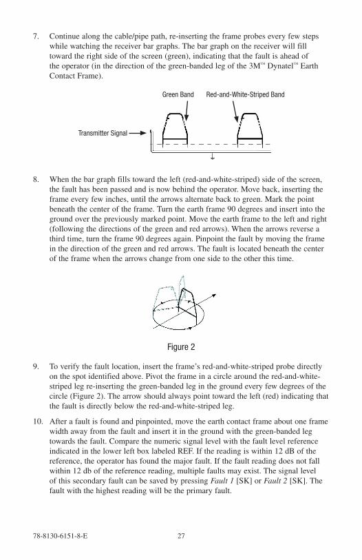
7. Continue along the cable/pipe path, re-inserting the frame probes every few steps while watching the receiver bar graphs. The bar graph on the receiver will fill toward the right side of the screen (green), indicating that the fault is ahead of the operator (in the direction of the green-banded leg of the 3M™ Dynatel™ Earth Contact Frame).
Transmitter Signal
Green Band Red-and-White-Striped Band
8. When the bar graph fills toward the left (red-and-white-striped) side of the screen, the fault has been passed and is now behind the operator. Move back, inserting the frame every few inches, until the arrows alternate back to green. Mark the point beneath the center of the frame. Turn the earth frame 90 degrees and insert into the ground over the previously marked point. Move the earth frame to the left and right (following the directions of the green and red arrows). When the arrows reverse a third time, turn the frame 90 degrees again. Pinpoint the fault by moving the frame in the direction of the green and red arrows. The fault is located beneath the center of the frame when the arrows change from one side to the other this time.
Figure 2
9. To verify the fault location, insert the frame’s red-and-white-striped probe directly on the spot identified above. Pivot the frame in a circle around the red-and-white-striped leg re-inserting the green-banded leg in the ground every few degrees of the circle (Figure 2). The arrow should always point toward the left (red) indicating that the fault is directly below the red-and-white-striped leg.
10. After a fault is found and pinpointed, move the earth contact frame about one frame width away from the fault and insert it in the ground with the green-banded leg towards the fault. Compare the numeric signal level with the fault level reference indicated in the lower left box labeled REF. If the reading is within 12 dB of the reference, the operator has found the major fault. If the fault reading does not fall within 12 db of the reference reading, multiple faults may exist. The signal level of this secondary fault can be saved by pressing Fault 1 [SK] or Fault 2 [SK]. The fault with the highest reading will be the primary fault.

28 78-8130-6151-8-E
3M™ Electronic Markers and 3M™ EMS iD MarkersE-Model Initial ConfigurationAttention: All E-Model iD Locators must run the initial configuration setup found in the 3M™ Dynatel™ Locator PC Tools software. Download the 3M™ Dynatel™ Locator PC Tools software at www.3M.com/dynatel.
Activating the Marker Locate Feature
In order to enable the electronic marker location feature of this receiver, you must identify the country in which the locator will be used. This initial configuration is required for the 2273ME-iD, 2250ME-iD, and 1420E locator receiver models.
Some countries do not allow all marker operating frequencies. Therefore, the E-model locators are shipped with all the marker types/frequencies disabled.
m WARNING
It is unlawful to operate this unit in any country with a configuration setting that is not specific to that country. In order to prevent the user from operating this unit with a configuration setting that is not specific to the country where it is operated, this unit is equipped with configuration software for installing country specific configurations.
1. Download the 3M™ Dynatel™ Locator PC Tools software from www.3M.com/dynatel and install it on your computer.
2. Close any programs that may be using the COM ports.
3. Start the software program; Dynatel PC Tool kit
4. Connect the receiver to the PC via the provided RS232 serial cable or RS232-to-USB Adapter cable.
5. Turn the receiver on.
6. From the main screen, select the country in which the unit will be operating. (If the country is not listed, select ‘All other countries’.)
7. A communication window will appear. (Baud rate 38400 / Com Port 1).
8. Press OK .
9. Press Initial Configuration .
10. Press Download .
11. The prompt line will display: Download Completed Successfully
12. Multiple units may be configured at this point by simply connecting the next receiver, turning it on, and pressing download.
13. Press Exit when all receivers have been updated.

78-8130-6151-8-E 29
Enabling/Disabling Marker TypesMenu [6] + Setup [SK] + Marker Type [SK]
The unit will default with all markers enabled (3).
1. Press the up/down arrows [SK] to highlight a utility to enable or disable.
2. Press Enabl/Disabl [SK].
− Only the markers that are enabled (3) will be available in the locate mode.
3. Press OK [5] to save settings or Exit [SK] to cancel.
Locating 3M™ EMS MarkersAlert Mode (3M™ Dynatel™ Models 2250ME-iD and 2273ME-iD only)While tracing a cable or pipe, it is possible to search for markers.
1. Press Alert [SK].
− If the unit is in DirPk or DirNull, a prompt will notify the operator that alert mode only functions in Special Peak mode.
2. Press Mode [SK Toggle] for SplPk.
3. Press Alert On [SK Toggle].
− The receiver screen will add the Alert bar graph and the type of marker to the screen with a prompt to adjust the marker gain.
4. Press the Gain Adjust [4] until only a small mark on the marker bar graph is visible.
5. Press Locate/OK [5] to save the marker gain setting.

30 78-8130-6151-8-E
− The screen will return to Special Peak Cable Locate / Alert On.
− If the selected type of utility marker is detected, a second audio tone will emit from the unit and the marker bar graph will fill. The marker utility will default to the last type of marker set in marker locate mode.
6. Press Locate [5] + Marker [SK] + Marker 1 [SK Toggle] to change the type of marker that the unit will detect in alert mode,
Single Marker Locate
1. Press Locate [5]
2. Press Marker [SK]
3. Press Markr 1 [SK Toggle] to select desired utility.
4. Markr 2 should be OFF.
Note: Only the marker types enabled in the setup menu will be shown. (See Enabling/Disabling Marker types). When scanning for markers, the gain level [12] should be set high.
− When a marker is detected, adjust the Gain Down [4] until the bar graph opens.
− The bar graph will close, the audio will be steady, and the signal strength will be maximum when the receiver detects a marker of the specified utility.
Dual Marker Locate
1. Press Locate [5].
2. Press Marker [SK].
3. Press MARKR 1 [SK Toggle] to select desired Utility.
4. Press MARKR 2 [SK Toggle] to select desired Utility.
Note: Only the marker types enabled in the setup menu will be shown.
− The third and fourth soft key commands will populate with the types of utilities selected for Marker 1 and Marker 2.

78-8130-6151-8-E 31
5. Adjust the Gain Down [4] until the bar graphs open.
− The bar graph will close, the audio will increase, and the signal strength will be maximum when the receiver detects a marker of the specified utility.
− When one of the two markers is detected, press the “XXX Only” [SK] for the detected utility marker.
− The unit will switch to Single Marker Locate in order to pinpoint the marker.
6. Press Markr 2 [SK Toggle] to return to Dual Marker Locate.
Marker Depth EstimateID Marker Depth1. Lower the tip of the receiver to the ground over the targeted marker.
2. Press Depth [SK].
− The receiver will examine the marker (Calculating, please wait...)
− If the marker is a 3M™ Dynatel™ iD Marker, the receiver will display the depth of the marker, and its identification number.
3. To save the depth reading, press Mem Select [SK].
− Five depth readings can be saved with the time, date, and its identification number.
− Save [SK] will place each entry in sequential order in memory (M1 - M5) until five readings have been stored. The unit will overwrite saved entries in excess of five, beginning with M1.
4. Press Clear All [SK] to delete all stored depth information.
5. Press Mem Select [SK] to select the memory location to store the depth readings. When the preferred location appears on the screen, press Save [SK]. The screen and memory location will populate with the current information.
6. Each memory location can be reviewed by pressing Mem Select [SK].
7. Press Locate [5] to return to Marker Locate Mode.

32 78-8130-6151-8-E
Depth of Passive, Non-iD Marker1. Lower the tip of the receiver to the ground over the targeted marker.
2. Press Depth [SK].
− The receiver will examine the targeted marker.
− The screen will instruct the operator to raise the unit 15.2 cm (6 inches) from the ground.
Note: This 15.2 cm (6-inch) rise must be exact for the depth reading to be accurate.
3. Raise the unit 15.2 cm (6 inches). Press Depth [SK] key again. The estimated depth of the marker from ground level will display on the screen.
− Five depth readings can be saved with the time, and date.
4. To access the memory locations, press Mem Select [SK].
− Save [SK] will place each entry in sequential order in memory (M1–M5) until five readings have been stored. The unit will overwrite saved entries in excess of five, beginning with M1.
5. Press Clear All [SK] to delete all stored depth information.
6. Press Mem Select [SK] to select the memory location to store the depth readings. When the preferred location appears on the screen, press Save [SK]. The screen and memory location will populate with the current information.
7. Each memory location can be reviewed by pressing Mem Select [SK Toggle].
8. Press Locate [5] to return to Marker Locate Mode.
78-8130-6151-8-E 33
Creating/Editing Templates for 3M™ EMS iD MarkersIn the User Template screen, the operator can create and modify templates to program iD markers.
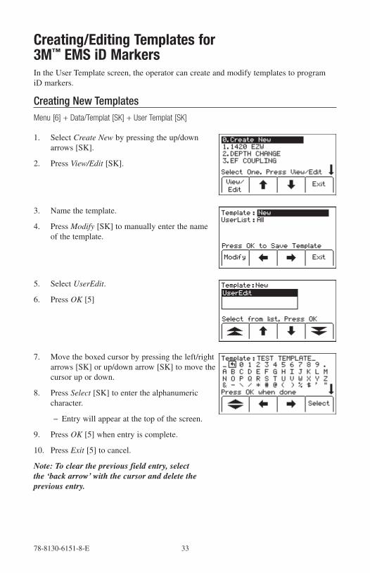
Creating New TemplatesMenu [6] + Data/Templat [SK] + User Templat [SK]
1. Select Create New by pressing the up/down arrows [SK].
2. Press View/Edit [SK].
3. Name the template.
4. Press Modify [SK] to manually enter the name of the template.
5. Select UserEdit.
6. Press OK [5]
7. Move the boxed cursor by pressing the left/right arrows [SK] or up/down arrow [SK] to move the cursor up or down.
8. Press Select [SK] to enter the alphanumeric character.
− Entry will appear at the top of the screen.
9. Press OK [5] when entry is complete.
10. Press Exit [5] to cancel.
Note: To clear the previous field entry, select the ‘back arrow’ with the cursor and delete the previous entry.

34 78-8130-6151-8-E
11. Navigate through the fields by pressing the left/right arrows [SK].
12. Press Modify [SK] to populate the highlighted field.
13. When modifying the Labels (left hand side of template information) there are three options for editing that are presented:
a. UserEdit
b. Choosing one of the common (compressed) terms from the available list of terms.
c. Del Row (delete row)
14. When modifying the Descriptions (right hand side of template information) there are four options for editing that are presented:
a. UserEdit
b. Delete Row
c. Last 10 UserEdits
d. Show All - lists common (compressed) terms
15. Populate as many fields as possible from the drop-down list of common (compressed) terms available to conserve marker memory space, or choose UserEdit if a term is not found to meet the user's requirements. Select term by pressing the up/down arrows [SK] and press OK [5].
16. When the template is complete, save the template by pressing OK [5].

78-8130-6151-8-E 35
17. Navigate to the next field by pressing the left/right arrow [SK].
18. Press Modify [SK] to populate the highlighted field.
Editing Templates
The operator can select an existing template and make changes to it in the same manner describe in Creating Templates. The following save screen will appear.
Over Write: Saves all modifications that have been made to the original template.
Rename: Overwrites the old template with the new name and all modifications. Screen will return to the template name field. Modify the name of the template and press OK [5] to save.
Save New: Creates a new template containing all information. Original template remains unchanged. Screen will return to the template name field. Modify the name of the template and press OK [5] to save.
Cancel: Clears all modifications made to any unsaved template.
Note: User templates can also be created on a PC using 3M™ Dynatel™ PC Tool Kit software and then downloaded to the receiver via the RS232 port [14] on the unit and the provided RS232 cable or RS232-to-USB adapter cable.

36 78-8130-6151-8-E
Writing iD MarkersThe Write Mode enables the user to write or program information into 3M™ EMS iD Markers. It is also possible to edit the information to be programmed.
Menu [6] + Write Mode [SK]
1. Select a template from the list on the screen to be programmed into the marker by pressing the up/down arrows [SK] to highlight the preferred template. ‘Last Written’ is the most recent data that was programmed to a marker by the receiver.
2. Press View/Edit [SK].
− The screen will display the information from the selected template. The arrow on the right side of the screen indicates there is more information than can be displayed on the screen (scroll down by pressing the down arrow [SK]).
3. Enter user information that will be written to this marker. (See Modifying Marker Data to be Programmed section.)
4. Verify all information is correct.
5. Press Write Marker [SK].
6. Select type of marker to be written Marker [SK Toggle].
7. Hold the receiver directly over the top of the marker. The receiver should be within 12 inches (30 cm) of the marker.
8. Press Start Write [SK].
− The receiver will ask if the user wants to permanently lock the marker data.

78-8130-6151-8-E 37
9. Select No [SK] or Yes [SK]. The receiver will write the data to the marker.
10. After writing to the iD Marker is completed, the following screen will displayed.
Note: Once the marker data has been locked, the information contained on the marker is PERMANENT. Choosing to permanently lock the marker data is irreversible. Once the data is locked it can not be overwritten. Assure that the data that is being written is correct before proceeding.
Modifying Marker Data to be ProgrammedTo alter the information to be programmed into the marker
1. Press Menu [6] + Write Mode [SK].
2. Select a template from the list on the screen to be programmed into the marker by pressing the up/down arrows [SK] to highlight the preferred template. ‘Last Written’ is the most recent data that was programmed to a marker by the receiver.
3. Press View/Edit [SK].
4. Press the up/down arrows [SK] to highlight the information to change.

38 78-8130-6151-8-E
5. Press Modify [SK]. The percentage displayed in the upper right portion of the screen indicates the remaining memory available on the marker.
6. The operator may select User Edit in order to ‘type’ the modification, or Delete Row to remove the entire row from the template, or select Show All to display a list of common terms.
Note: Using a common term requires less memory in the marker.
7. Select an option from the list by pressing the up/down arrows [SK]. Press OK [5].
8. If User Edit is selected, the following screen will appear.
9. Move the boxed cursor to the ‘back arrow’ and press Select [SK] to delete the entry to be modified.
10. Move the boxed cursor by pressing the left/right arrows [SK] or the Up/ Down Arrow [SK] to move the cursor to the next row.
11. Press Select [SK] to enter the alphanumeric character.
− Entry will appear at the top of the screen.
12. Press OK [5] when entry is complete.
13. If Show All is selected, the following screen will appear.
14. Select a common term from the list by pressing the up/down arrows [SK].
15. Press OK [5]. The modification will automatically populate the marker template.
Reading iD MarkersThe operator can retrieve the data from the iD marker by pressing Read [SK] (on the locate screen or the depth screen).
The receiver tip should be lowered to the ground to reach maximum read depth.
If more than one 3M™ EMS iD Marker of the same utility is detected, the receiver will read the first marker and display the data from the marker.

78-8130-6151-8-E 39
The fourth yellow command key will be labeled “Read Next”. Press this key to extract the data from the other marker.
All the information retrieved from the marker, including the date and time read, is saved into the ‘Read History’ file of the receiver. If a hand-held GPS unit is used in conjunction with the receiver, coordinates can be saved into the Read History. (See Reviewing Marker History)
GPS OperationActivation KeyTo activate the GPS compatibility in the receiver, an activation key must be entered into the receiver. The software version of the receiver must be at least 14.0. For the receiver to transmit information to the GPS for use in GIS mapping applications (see Capture/Transmit Mode), the hardware version must be 5.0 or higher. (See Serial Number & Software Version Section.)
The software upgrade and activation key can be obtained from the website http://www.3m.com/dynatel for no charge. You will be asked to enter the serial number of the receiver in order to receive the GPS activation key.
Upgrade the software of the receiver using the desktop software: 3M™ Dynatel™ PC Tool Kit, then enter the GPS activation key on the receiver.
Serial Number and Software VersionMenu [SK] + More>> [SK] + Self Test [SK]
The model number, software version, hardware version, and serial number of the receiver are available on the Self Test Screen.
Inputting the GPS Activation KeyMenu [SK] + Setup [SK] + More>> [SK] + Com [SK]
Initially, when the COM key is pressed, the screen below will appear and you will be prompted to input the activation key that you have obtained from the website. This will have to be performed only one time to enable the GPS interface.
1. Move the selector box left or right by pressing the arrow keys [SK].
2. Press Select [SK] to enter each number.
3. Press OK [5] to activate.

40 78-8130-6151-8-E
Communicating with the GPS unitMenu [SK] + Setup [SK] + More>> [SK] + More>> [SK] + Com [SK Toggle]
After the GPS interface has been activated, the Com [SK] will toggle through several options to configure the RS232 port of the receiver (depending on the application, or capabilities of the GPS unit). Select from the following options.
NMEA – The RS232 Port is configured to receive NMEA signals from a GPS unit (4800 Baud Rate). (Capture Mode/Mode 1)
GIS – The RS232 Port is configured to send and receive data to a GPS unit that has GIS mapping capabilities. (Capture/Transmit Mode/ Mode2)
PC – The RS232 Port is configured to communicate with a computer for the Dynatel PC Tool Kit application
PDA - The RS232 Port is configured to only send information if the GPS unit only has the ability to receive information.
Capturing the GPS Coordinates (Capture Mode / Mode 1)Menu [SK] + Setup [SK] + More>> [SK] + More>> [SK] + Com [SK Toggle] + NMEA
If the GPS unit is not configured properly, there is an error communicating with the receiver, or the GPS has not acquired enough satellites to pinpoint the location, the receiver will display the message “Insert External Device”.
When the receiver is communicating with a GPS unit, the LAT and LONG coordinates received from the unit will appear on the marker locate screen.
1. Locate a marker (See Locating Single Marker.)
2. Press Read [SK]
The information from the iD marker will display on the receiver screen, as well as the GPS coordinates. This information is saved automatically in the Read Marker History. (See Reviewing Read History.)
If the marker is a passive marker (rather than iD) the receiver will display “No iD Marker Found”. The GPS coordinates of the attempt to read the non-iD marker are stored in the Read Marker History as serial number # 0000-0000-0000. The marker details will indicate “not an iD marker”, but will display the GPS coordinates.

78-8130-6151-8-E 41
Sending iD Data to GPS (Capture-Transmit Mode / Mode 2)Menu [SK] + Setup [SK] + More>> [SK] + More>> [SK] + Com [SK Toggle] + GIS
Receivers that have marker locating capability (indicated by ‘iD’ in the model number) can be configured to send 3M™ EMS iD Marker data directly to some GPS devices. When a marker is located and read, the information read from the iD marker with feature and attribute data is sent to the GPS device and is stamped with latitude, longitude and date/time data. The data acquired during this logging process can be uploaded to GIS mapping software. For more information and detailed instructions pertaining to specific GPS units, refer to www.3M.com/dynatel GPS instruction sheet.
Path Mapping with GPSThe M-Series cable and pipe locators are compatible with hand-held GPS devices and now have the ability to map the path of under ground target facilities. While measuring the depth to the target, the technician can automatically log the coordinates of the path on the GPS device. These logged points contain the Trace template that can have valuable information regarding the facility (owner, utility, size, etc.) and the method used to find the path (frequency, current, and measured depth).
In order to transmit the path information to a GPS device, the GPS has to have the ability to accept information on one of its com ports at 4800 Baud. Using the manual supplied with the GPS device, configure the com port of the GPS to communicate with the receiver.
If ArcPad™ is the mapping software on the mobile device, download the 3M software application script from the website: www.3M.com/dynatel
With 3M’s ArcPad™ application installed, the receiver will send the path information (locate frequency, depth, current, and trace template information) into the software program as a logged point and can be saved as a .shp file.
Create Trace TemplatesThe easiest way to create a Trace template is using the Dynatel PC Tools software. (Software available for no charge at www.3M.com/dynatel - 3M™ Dynatel™ M-Series Locator PC Tools).
1. Create a TRACE template.
2. Save and download the template to the receiver.
Up to four Trace Templates can be stored on the Receiver.
Each Trace template is limited to 132 user editable characters.
The trace template appears in table format: two columns with six lines.
The first column is limited to 8 characters and the second column is limited to 14 characters. In addition to the 132 character table, the receiver will send a sequence number, the frequency, the measured depth of the conductor, and the current to the GPS.

42 78-8130-6151-8-E
Select Com Port SettingMenu[6] + Com [SK] + GIS [SK] (or PDA [SK])
If the GPS has the ability to send NMEA coordinates on its com port and has the ability to receive information at 4800 baud, set the receiver’s com port to GIS.
If the GPS only has the ability to receive information, set the com port of the receiver to PDA mode.
Log Prompt = On: Before the receiver returns to locate mode, a verification screen will pop up on the receiver with the trace template information that will be sent to the GPS device. This information can be modified and confirmed. Press OK to send to GPS.
Log Prompt = Off: When the receiver returns to locate mode, the trace template and locate information will be sent automatically to the GPS.
Sending Path Information to GPS Device1. Establish communication on GPS unit.
2. Set com port on receiver.
3. Locate target utility.
4. Measure depth to target utility.
− If Log prompt is activated, when the Locate button is pressed (or after a five second delay) a screen will appear that displays the path information.
5. Press OK to send the information to the GPS, or Exit to abort the exchange.
For more information refer to the software release notes at www.3M.com/dynatel

78-8130-6151-8-E 43
Reviewing Marker HistoryRead HistoryThe Read History mode is a historical file of all information that has been read from targeted markers (100 memory locations).
Menu [6] + Data/Templat [SK] + Read History [SK]
The Read History screen displays the date and time that each marker was read, and its unique identification number.
1. Select the marker data to be viewed by pressing the up/down arrows [SK]
2. Press Marker Details [SK] to view all data that was retrieved from the marker.
3. Press Read History [SK] to return to list or press Exit [SK] to return to Data/Template review screen.
Write History [SK]Menu [6] + Data Templat [SK] + Write History [SK]
1. Select the marker data to be viewed by pressing the up/down arrows [SK].
2. Press Write Details [SK] to view all data that was sent to the marker.
3. Press Write History [SK] to return to the list of programmed data.
4. Press Exit [SK] to return to Data/Template review screen.
For additional information concerning 3M™ iD Marker Programming, refer to www.3M.com/dynatel - Instruction Manual M-Series Locator PC Tools.

44 78-8130-6151-8-E
Other ApplicationsAerial Faults (Toning)Transmitter Setup
1. Connect the transmitter (based on type of fault) as described in Connection Diagrams in the following section.
2. Press and hold [T-1] to perform a battery test.
3. Press OHMS/FAULT/TONE [T-2] to turn the Transmitter on and to verify the fault.
4. Press OHMS/FAULT/TONE [T-2] twice more to select the Tone mode.
5. The display [T-4] will alternately flash between 577 and 133K.
6. Press OUTPUT [T-5] for high output level.
Receiver Setup
1. Press ON/OFF [1] to turn the Receiver on.
2. Press Locate [5]
3. Press Tone/Ext [SK] to select Tone mode.
4. Press Freq [SK Toggle] to select 577Hz.
5. Connect a toning coil to the receiver EXTERNAL JACK [13].
6. Move the toning coil along the cable and find a peak signal then press Gain/Down [4] to adjust the receiver gain.
7. Press SPEAKER [2] to adjust the speaker volume as needed.
8. Follow the cable with the toning coil.
− When the receiver detects a short, cross, or ground fault (Connection Diagrams #1, #2, or #3), the audio and signal strength will stop or drop off sharply.
− When the receiver detects a split (connection #4) the audio and signal strength will increase significantly.
− When verifying a split (connection #5) the audio and signal strength will decrease after the toning coil has passed the split.
Connection DiagramsShort:
Figure #1 Red clip to Tip; Black clip to ring.

78-8130-6151-8-E 45
Cross:
Figure #2 Red clip to the crossed conductor of one pair; Black clip to the crossed conductor of the other pair.
Ground:
Figure #3 Red clip to the faulted conductor; Black clip to ground.
Split:
Figure #4 Red clip to Tip of Pair 1; Black clip to Ring of Pair 1.
Verify Split:
Figure #5 Red clip to good conductor of Pair 1; Black clip to split conductor of Pair 2
Cable IdentificationTransmitter Setup1. Connect the 3M™ Dynatel™ Dyna-Coupler to the Transmitter output jack [T-6] using
the coupler cable.
Note: Cable Identification requires two Dyna-Couplers: one at the Transmitter and one at the Receiver.
2. Clamp the Dyna-Coupler around the cable or both the tip and ring of a pair. Make sure the jaws fully close.
3. Press and hold [T-1] to perform a battery check.
4. Press OHMS/FAULT/TONE [T-2] three times to set the transmitter to Tone mode.
− The indicator flag will light in the display [T-4] under the tone icon.
5. Press OUTPUT [T-5] for high output level.
− The indicator flag will light in the display [T-4] above the output icon.
− The display [T-4] will alternately flash between 577 and 133K.
46 78-8130-6151-8-E
Receiver Setup1. Press ON/OFF [1] to turn the receiver on.
2. Press Locate [5].
3. Press Tone/Ext [SK] to select Tone mode.
4. Connect a second coupler to the Receiver’s EXTERNAL JACK [13] using the earth frame cable or another coupler cable.
5. Press Freq [SK Toggle] to select the highest transmitter frequency (133K).
6. Check the first cable in the group by clamping the coupler around the cable.
7. Press Gain/Down [4] and observe the numerical signal strength [10].
8. Remember the number and continue by clamping the coupler around the next cable in the group.
− If the signal strength [10] is greater than the previous observation, press Gain/Down [4].
− If the signal strength is less than before, ignore it.
− After checking all the cables in the group, the cable with the highest reading is the target cable.
Help ModeMenu[ 6] + More>> [SK] + Help [SK]
The help screen contains basic information about the unit and its operation. It is designed to be a quick reference guide.
1. Press the double up/down arrows [SK] to navigate between sections.
− The single up/down arrows [SK] will scroll the screen line by line.
3M™ Dynatel™ PC Tool KitThe Dynatel PC Tool Ksoftware is available for download, at no cost, at www.3M.com/dynatel.
The Dynatel PC Tool Kit provides the user an excellent interface between the receiver and a PC. This software utility provides the tools by which the user can:
• Upgrade the receiver to the latest software revision
• Program the receiver to best suit specific applications
• Load an alternate language in the receiver
• Provide a 3M™ EMS iD Marker utility.
The 3M™ EMS iD Marker utility can be used to:
• Create templates for programming iD markers

78-8130-6151-8-E 47
• Download marker data that has been programmed or read by the receiver for documentation databases.
Embedded in the desktop software is the most current software for the receiver, which affords the user the option of upgrading the unit without returning the unit to the 3M Repair Center.
Please refer to operating instructions included with the software.
Self Test Of ReceiverMenu [6] + More>> [SK] + Self Test [SK]
This operation performs a self-test on the receiver.
The receiver will display current information about the unit (model number, serial number, software revision, and hardware revision).
1. Press RUN [SK] to start the self test.
− A status bar will appear while the self test is running.
− Results will appear on the screen when the test is complete.
Product Description And Optional AccessoriesProduct Description
Example: 2273M-iD/EC3W-RT
Description: 2273M Cable/Pipe/Fault Locator / iD capability; Export version; Communication Application; 3-Watt Transmitter; Receiver and Transmitter included.

48 78-8130-6151-8-E
Package Contents
Standard Packages
2250ME
2250ME-iD
2273ME
2273ME-iD Part Number
Transmitter• • 2250E; 3 or 12 Watt
• • 2273E; 3 or 12 Watt
Receiver w/o EMS• 2250M-ER
• 2273M-ER
Receiver w/EMS• 2250M-iD/ER
• 2273M-iD/ER
Ground Rod • • • • 8006
Dyna-Coupler Kit (3" [76 mm] Dyna-Coupler, Coupler Cable, & Pouch)
• • • • 3019
Direct Connect Cables • • • •2876 (Utility - 10' [3 m])
9012 (Communication - 5' [1.5 m])
Earth Contact Frame • • 3014
Earth Contact Frame Cable • • 9026
Optional 3M™ Dynatel™ Accessories
Item Part Number
Direct Connect Cables Communication 10' (3 m) 2892
Ground Extension Cable 9043
Dyna-Coupler 3" (75 mm) 3001
Dyna-Coupler 6" (150 mm) w/ pouch 1196
Coupler Cable 12' (3.6 m) 9011
Rechargeable Battery 2200RB
Carrying Bag 2200M
ADP 33 KHz Sonde 3229

78-8130-6151-8-E 49
Receiver SpecificationsItem Specification
Modes Directional PeakDirectional NullSpecial Peak Induction Peak
Frequency Response: Active 577 Hz
8 KHz33 KHz133 KHz
Passive 31.5 KHz (CATV)9 – 30 KHz (LF)
Power 50 Hz (5th and 9th harmonic)60 Hz (5th and 9th harmonic)(100 / 120 Hz) rectified power
Auxiliary 333 Hz512 Hz560 Hz
User Defined Frequencies Four
Display LCD
Gain Control Manual and Automatic
Weight w/batteries 1.8–2.3 kg (4–5 lbs.) (model dependent)
Battery Qty. and size 8 AA (LR6)
Battery Life 30 hours average
Depth Accuracy ±2% ± 5 cm (2 in.) for 1.5 m (0–60 in.)±6% ± 5 cm (2 in.) for 1.5–3.0 m (60–120 in.)±10% ± 5 cm (2 in.) for 3.0 m–4.5 m (120–180 in.)
Depth Range 0–914 cm (0–360 in.)
Marker depth accuracy ± 15% ± 5 cm (2 in.)
Maximum Program Range 3M EMS iD Markers Near-Surface Ball Marker Full-Range
15 cm (6 in)30 cm (12 in)61 cm (24 in)

50 78-8130-6151-8-E
Item Specification
Read Range 3M EMS iD Markers Near-Surface Ball Marker
Full-Range
60 cm (24 in)1.2 m (48 in) (Tel, Gas, WW, Comm)1.0 m (40 in) (Pwr, Wtr)2.0 m (78 in)
Detection Depth 3M Passive Markers Near Surface Ball Marker Mid-Range Full-Range
60 cm (24 in)1.5 m (60 in)1.8 m (72 in)2.4 m (96 in)

78-8130-6151-8-E 51
Transmitter SpecificationsItem Specification
Trace Mode 577 Hz8 KHz33 KHz133 KHz
Fault Mode 10/20 Hz -Fault signal 577 Hz / 33 KHz -Trace signal
Tone Mode 577 Hz and 133 KHz @ 8 Hz
Induction Mode 33 KHz 133 KHz
Output Power 3 Watt Transmitter - .5W (normal), 3W (high)5 Watt Transmitter - .5W (normal), 3W (high), 5W (max) w/external DC source12 Watt Transmitter - .5W (normal), 3W (high), 12W (max) w/external DC source
Output Voltage (Maximum) 70 Vrms
Output Protection 240Vrms
Weight w/batteries 5.2 lbs (2.4 kg)
Battery Qty. and size 6 "C" Alkaline (LR14)
Battery Life 50 hours typical (Normal output level) 10 hours typical (High output level) Rechargeable battery will extend operation time by 40%
External DC Power 9–18 V DC
Standard IP54
Regulatory CE
Operating Temperature 4°F to 122°F (-20°C to 50°C)
Storage Temperature -4°F to 158° F (-20°C to 70°C)
Rechargeable Battery fuse 5 Amp / 32 VoltLittelfuse MINI® Blade # 0297005

3M and Dynatel are trademarks of 3M Company. ArcPad is a trademark of ESRI. MINI is a registered trademark of Littelfuse.
Important NoticeAll statements, technical information, and recommendations related to 3M’s products are based on information believed to be reliable, but the accuracy or completeness is not guaranteed. Before using this product, you must evaluate it and determine if it is suitable for your intended application. You assume all risks and liability associated with such use. Any statements related to the product which are not contained in 3M’s current publications, or any contrary statements contained on your purchase order shall have no force or effect unless expressly agreed upon, in writing, by an authorized officer of 3M.
Warranty; Limited Remedy; Limited Liability. This product will be free from defects in material and manufacture for a period of one (1) year from the time of purchase. 3M MAKES NO OTHER WARRANTIES INCLUDING, BUT NOT LIMITED TO, ANY IMPLIED WARRANTY OF MERCHANTABILITY OR FITNESS FOR A PARTICULAR PURPOSE. If this product is defective within the warranty period stated above, your exclusive remedy shall be, at 3M’s option, to replace or repair the 3M product or refund the purchase price of the 3M product. Except where prohibited by law, 3M will not be liable for any indirect, special, incidental or consequential loss or damage arising from this 3M product, regardless of the legal theory asserted.
3Track and Trace Solutions6801 River Place Blvd.Austin, TX 78726-90001-800-426-8688http://www.3M.com/dynatel
Please Recycle. Printed in USA.© 3M 2009. All Rights Reserved.78-8130-6151-8-E
This product is in accordance with the requirements of the European directive 99/5/EC.
This is the EU symbol for equipment that is covered under the Waste from Electrical and Electronic Equipment (WEEE) directive per CENELEC Specification 5041. It indicates that certain products should not be discarded in the trash, but rather should be recycled. This applies to all electronic pluggable and battery powered products.
This is the EU symbol for equipment that is covered under the Waste from Electrical and Electronic Equipment (WEEE) directive per CENELEC Specification 5041. It indicates that certain products should not be discarded in the trash, but rather should be recycled. This applies to all electronic pluggable and battery powered products.