3He Refrigerator Instsallation and Operation Manual · Check for flow on the 1K pot a. close needle...
10
1 3 He Refrigerator Installation and Operation Condensed Matter NMR 2014 Fig. 1 The 3 He cryostat loaded into the dewar. See Fig. 2 for valve identification. The Condensed Matter Nuclear Magnetic Resonance group utilizes and maintains a Janis 3 He refrigerator for low temperature NMR experiments. The system operates using a charcoal absorption (sorp) pump which is in direct contact with 3 He gas within the cryostat. The 3 He gas, also in thermal contact with the L 4 He 1K Pot, is first liquefied by pumping on the pot below 3.2K while keeping the sorp at high temperatures (>40K). Thereafter, the charcoal is cooled down by circulating L 4 He into the sorp. The large surface area of the charcoal cryo‐pumps the gas resulting to lower 3 He vapor pressure. Through evaporative cooling, the low vapor pressure causes the liquid 3 He to cool below its boiling point, down to typically 0.3K. Because of the delicate nature of this equipment, extreme care has to be taken in order to avoid possible damage to its structure or, most importantly, loss of 3 He gas to the atmosphere. This manual contains a lot of useful information for proper and efficient operation of the 3 He system. First time users of this equipment are required to read (and understand!) this manual in its entirety before attempting to operate the system. GATE VALVE LN2 PORT IVC PORT HOISTING LUG N2 VENT PORT He‐4 VENT PORT SENSOR CABLES LEVEL SENSOR SORP THROTTLE NEEDLE VALVE (behind) SORP PUMPOUT 3 He PORT 1K POT PUMPOUT T5 V12 V15 M2 T6 V6 T4 MAIN DEWAR HOUSE VAC PORT
Transcript of 3He Refrigerator Instsallation and Operation Manual · Check for flow on the 1K pot a. close needle...

1
3He Refrigerator Installation and Operation
Condensed Matter NMR
2014
Fig. 1 The 3He cryostat loaded into the dewar. See Fig. 2 for valve identification. The Condensed Matter Nuclear Magnetic Resonance group utilizes and maintains a Janis 3He refrigerator for low temperature NMR experiments. The system operates using a charcoal absorption (sorp) pump which is in direct contact with 3He gas within the cryostat. The 3He gas, also in thermal contact with the L4He 1K Pot, is first liquefied by pumping on the pot below 3.2K while keeping the sorp at high temperatures (>40K). Thereafter, the charcoal is cooled down by circulating L4He into the sorp. The large surface area of the charcoal cryo‐pumps the gas resulting to lower 3He vapor pressure. Through evaporative cooling, the low vapor pressure causes the liquid 3He to cool below its boiling point, down to typically 0.3K. Because of the delicate nature of this equipment, extreme care has to be taken in order to avoid possible damage to its structure or, most importantly, loss of 3He gas to the atmosphere. This manual contains a lot of useful information for proper and efficient operation of the 3He system. First time users of this equipment are required to read (and understand!) this manual in its entirety before attempting to operate the system.
GATE VALVE
LN2 PORT
IVC PORT
HOISTING LUG
N2 VENT PORT
He‐4 VENT PORT
SENSOR CABLES
LEVEL SENSOR
SORP THROTTLE
NEEDLE VALVE (behind)
SORP PUMPOUT
3He PORT 1K POT PUMPOUT
T5
V12
V15
M2
T6
V6
T4
MAIN DEWAR
HOUSE VAC PORT

2
I. Preparatory Procedures 1. Preparing the vacuum systems a. Leak‐test the cryostat inner vaccum chamber (IVC, port V15), with particular attention on the two
In o‐ring seals above and below the sorp section. Test for possible internal (3He space) leak as well. Make sure the inside 3He space is dry.
b. Leak‐test the main dewar vacuum OVC (port V16), particularly the three o‐ring seals outside and the inner joints inside. Make sure the space inside the dewar is dry.
c. Evacuate the IVC, main dewar vacuum, and the 3He space. Pump for 2‐3 days. 2. Loading the main dewar into magnet a. Secure the main dewar onto hoist using harness. Aim the tail to the magnet. b. Use a torpedo level to make sure the tail is vertical and goes straight to the magnet. c. set the correct height so that the NMR probe reaches the bottom of the tail. d. in Cell2, 3 legs are adjusted to 135mm. 3. Precooling the main dewar(LN2) a. Secure a full LN2 storage dewar. b. remove the rubber stopper on the LN2 port and hook up the LN2 line to LN2 dewar. c. open LN2 vent port and begin transfer until full. It takes about 30 mins to complete the transfer. 4. Precooling the main dewar (LHe) a. Wait 8 hours to allow the dewar tail to cool down to 77K b. Transfer Helium slowly to the main bath using the LHe port at <2 psi pressure. Fill halfway (30 cm) using its own level meter). Use extended tube to fill LHe.
5. Preparing the NMR probe a. Use the short loadlock for the long tail 3He cryostat and vice versa. See Fig. 4 for length reference. b. By capping the bottom of the loadload on the bench, leak test the loadlock and probe.
II. Loading the cryostat into the main dewar With LHe in the dewar, the cryostat may be loaded. The main dewar is capped by a black disk. (Note: if the cryostat is loaded before LHe4 transfer,the liquid helium may not go into the tail). 1. Evacuate 3He space and close the gate valve. 2. Close the needle valve and valves V7, T5, T4, V6, and T6. 3. Install the two lifting posts and mount the cryostat onto the hoist. 4. Remove the dewar cap and lower the cryostat into the dewar very slowly (~30 min). Use lots of rags to minimize moisture intrusion. Align cryostat tail manually as it gets through the dewar tail.
5. Orient the cryostat for most efficient access to ports. 6. When loaded, secure the cryostat flange into the dewar with six bolts. 7. Remove lifting posts. 8. Optional: fill the LHe to 60cm using a short transfer tube.

3
Fig. 2 3He Refrigerator System Interconnect. Dotted lines are connected only when the probe is loaded.
3He DUMP
V1 V2 V3
3He MANIFOLD
P1 P2 P3
S1 CLOSED CYCLE PUMP
OUT
IN
S3
S2
V7 T1 T5 TO HOUSE VAC
BALLAST
CRYO
TURBO PUMP
R1 R2
R3
GENERAL PUMPING
P1 – port NW16 to insert (REAR) P2 – Sorption Pump port (FRONT) P3 – NW16 GHS PUMP PORT (REAR) 1” bellows ½” bellows
G1
M2T4
V6
T6
M3
CHARCOAL1K POT
V4
3He
NEEDLE VALVE 4He Bath
M1
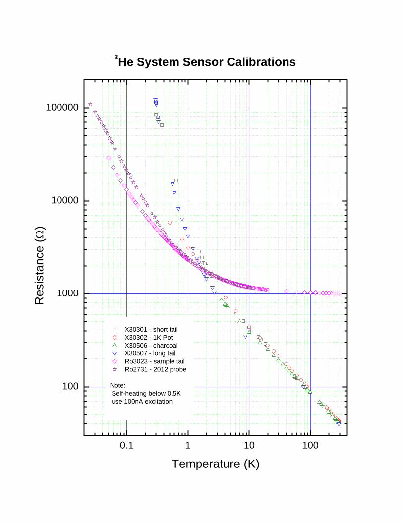
Sensor Location Type Serial No. A Charcoal Cernox X30506 B RuOx sample RuOx RO3023 C 1K‐Pot Cernox X30302
D Tail (Long) Cernox X30507 Tail (Short) Cernox X30301
Table I. Sensor Connections for LS340
G2
V10
V9
LOADLOCK
V12
4
III. Initial Cooldown Initial cooldown is required before introducing 3He in the fridge.
1. Connect the sensors. (See Table 1). Connect the charcoal heater to the LS controller heater output. 2. Hook up the house vacuum to the 1K Pot. 3. Open house vac valve and open T5 to clear the line. 4. Check for flow on the 1K pot a. close needle valve, close V6 (charcoal) valve b. open T5, evacuate by opening house vac valve, close T5. c. open needle valve, pressure reading should go up. Slight boil off expected d. close needle valve. 5. Check for flow on the charcoal circuit a. open T5, evacuate by opening house vac valve, close T5 b. open V6 and T4 and then slowly open T6, pressure reading should go up. c. close T4 and leave V6 open. 6. Keep T5 open and start pumping on the 1K pot. Set needle to 3‐4 turns to fill the pot with LHe.
Then close needle to 1.5 turns. Cooldown rate would depend on the pressure on the house vac manifold. As the temperature drops to 4K, close needle valve 3/4 turns.
7. Use T6/M3 to adjust the flow thru the charcoal. The tail temperature should slowly cool 200K/12 hrs, 0.25K/min.
IV. System plumbing Hook up the 3He storage manifold cart and turbo pump to the system as in Fig. 2. Leave the probe and the loadlock out. V. Loading 3He gas Note: as of 4/21/2014 the 3He pressure G1 in the dump is ‐8+ inHg. Although 3He can be loaded anytime, it is recommended to load 3He when the tail is already cold. Note: 3He liquefies at 3.2K.
1. Hook up the plumbing system (step IV, Fig. 2). Make sure valves T1, V7, S1, S2, S3, R1, R2, R3, V1, V2, and V3 are closed.
2. Turn on the turbo pump. 3. Open T1, S1, V3, R1 and R3 to clear the lines. Open V7. 4. Pump until the turbo pressure M1 is <10‐5 mbar. 5. Close R1 and V3 and seal them to avoid accidental opening. 6. With 1K‐pot at 1.5K and charcoal ~4K, introduce excess 3He from the ballast. Close V2, open V4 and then slowly open V2. Pressure G2 must indicate ‐30 inHg. This will warm up the charcoal to ~25K, but not change the tail temperature. Rapid change in tail temperature indicates a leak. Close V2 and V4.
7. Introduce 3He gas into the fridge: Open V1. Charcoal will absorb all the 3He. When all is transferred, pressure G1 must register ‐30 inHg.
8. Set 1K pot needle valve 3/4 turns. This will run full. Pressure regulator may be used to control the flow.
9. Start to liquefy, heat up the charcoal 30‐40K to push 3He to the tail and liquefy. It takes about 2hrs to condense the 3He gas in the tail.
5
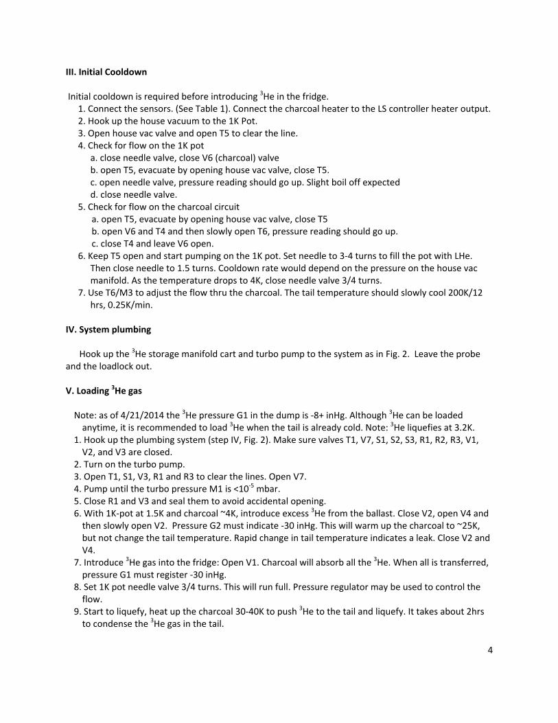
VI. Loading the 3He NMR probe The NMR probe is loaded when the tail is full of L3He. NMR probe is mounted on the loadlock. 1. Measure the distance between the sample and the probe head. See Fig. 4 for reference. 2. Align the bottom of the probe with the copper anchor and the bottom of the loadlock. (Fig. 4) 3. Mark the location of the upper end of the loadlock on the loadlock shaft. 4. Mark the location of the upper end of the loadlock shaft on the probe shaft. 5. Leak‐test the probe with the loadlock attached. 6. Set the loadlock on the KF flange on top of gate valve V12. 7. Connect the turbo pump to the loadlock. 8. Pump the loadlock and the loadlock seal (open R2, R3, V9, and V10) )until M1 reads ~10‐5mbar. 9. Close V10. Keep V9 open with the pump connected to it. 10. Heat charcoal to 25K to provide small exchange gas. 11. Open the gate valve V12. 3He gas should rush to the loadlock. 12. Connect the temperature controller to the probe. 13. Lower the loadlock shaft slowly 2 in. at a time until the copper thermal anchor hits the pot. Monitor the probe temperature while lowering. Use heater to control ramp to desired rate.
14. Lower the probe to the desired height. 15. Tighten the loadlock quick‐connect nut.
Fig. 3. Experimental asymptotic L3He temperature as a function of charcoal temperature determined by NMR. The 1K Pot is at 1.2K. Actual temperature may vary depending on the heat load.
5 10 15 20 25 30200
400
600
800
1000
1200
1400
3 He
Tem
pera
ture
(mK
)
Charcoal Temperature(K)

1298
1742
1166
722
TWENTY-TWELVE PROBE
1450
(to
end
of 3
/4" t
ubin
g)
2925
(to
mag
net c
ente
r with
gon
iom
eter
)
CHARCOALSIPHON LINE
2920
119011
4385
7
1549
2248
2634
634
102
4489
LONG TAILCRYOSTAT
343
FIG. 4
SHORT TAILCRYOSTAT
Cu THERMALANCHOR
CHARCOALSORP PUMP
1K POT SIPHON LINE
IVC
1K POT
480
He-4 LEVEL/VENT
IK POT PUMPOUT PORT
NEEDLE VALVE
N2 VENT
V7
635
GATE VALVE
V6CHARCOALPUMPOUT
PORT
LHe PORTIVC PORT
OVC
LN2 PORT
V16
V15
LOAD LOCK
3/4" QUICK-CONNECT TO PROBE
V12
V9
G3
V10
The 3He SYSTEM (DIMENSIONS in mm. SCALE 1:12)
1196
OLD 3HE PROBE
3He LOADLOCKPRELOAD DIMENSIONS
150060
10
0 mm 0 in
500 20
1000
30
40
50
SHO
RT L
OAD
LOCK
70
LONG
LO
ADLO
CK
200080
90
2500100
3000
110
120

7
VII. Operating the Fridge Under normal operation, the 3He fridge is open all the way to the dump, i.e. V1, S1, T1 and V7 are open. The L4He comsumption is pretty good: need only to transfer every 2 days. The needle valve is set at ¾ turns during the run for max efficiency. (<1/2 is better!)
1. To liquefy 3He gas, keep charcoal at 30K. It takes ~2 hrs to fill the tail with L3He. (How to find out?) 2. To cool down <1.5K, cool the charcoal (see temperature chart, Fig. 3) 3. For standby operation, e.g. overnight, leave the charcoal at 4K. 4. Fig. 3 can serve as a guide in using the sorp temperature to regulate the L3He temperature. The actual temperature may vary depending on the thermal load.
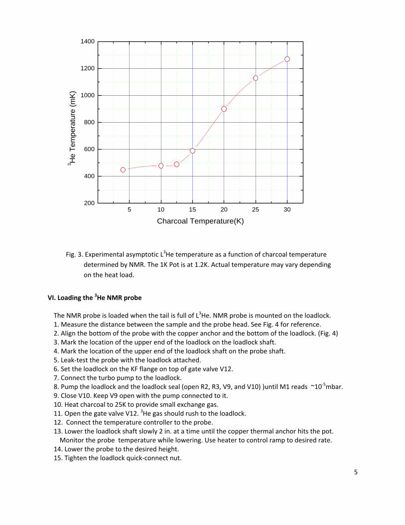
5. Fig. 5 details the P‐T curves of the two helium isotopes.
VIII. Unloading the NMR probe To unload the NMR probe, check that pot is at max 1.2K, L3He in tail, charcoal > 32K. Sample at 1.3K. The temperature controller is connected to the probe. Turbo pump is connected to the loadlock with V9 and V10 closed. 1. Pull the probe up to the mark made in Step VI.4 (see Fig. 4 for dimensions). As the probe is pulled
up, it warms to 25K as it passes through the sorp section and then back down when it goes past above IVC and then up again as it reaches the neck of the cryostat.
2. Pull loadlock shaft slowly, 1 ft at a time, up to mark made in Step VI.3. Open and close V9 for every pull to prevent air from getting in.
3. Wait until the sample is at room temperature. 4. Open V6, T6 and T4 to cool down the charcoal to 4K and cryopump the 3He gas. 5. Close the gate valve V12 carefully. Make sure gate does not hit the probe or the copper thermal
anchor. 6. Disconnect the turbo pump (hooked in Step VI. 7) from the loadlock 7. Open V10 to vent the loadlock. 8. Remove the loadlock and the probe fom the cryostat.
IX. Recovering 3He gas With the probe removed, the 3He gas may be recovered. 1. Disconnect the turbo pump from P3. 2. Connect the charcoal heater to 14VDC variable power supply and heat slowly to get to ~180K 3. Heat the tail to 160K(set to Lakeshore to 10mW power). 1K pot warms up to 50K 4. Pressure G1 on the manifold should go up (note V2 and V4 are both open) 5. Close S1, open S2 and S3 on the close cycle pump to suck out the residual 3He gas. Pressure at G1 should slowly go up to 7‐8 inHg.
6. Close T1, V7. Then close T5, T4, and V6. 7. Close S2. 8. Close S3 and shut off the closed‐cycle pump.
8
X. Clean Up procedure This procedure to be done only if the entire 3He gas has been recovered to the dump. 1. Remove the line connecting T1 and S1/S2. 2. Hook up the hoist and remove the cryostat from dewar. Cap the top of the dewar. 3. Disconnect the vent lines from the dewar. 4. Hoist up the dewar from magnet. Keep the vents open if helium is still in the system.
Fig. 5. P‐T curve of two isotopes of Helium.

9
APPENDICES A. EQUIPMENT DATA
Base temperature: 400mK (when 2012 probe is loaded) Hold time: 11 hrs at base temperature Cycle time 300mK to RT and back down: 2 hrs minimum Dump capacity: 30 liters STP 3He gas volume: 21 liters (‐7 inHg as of 5/2014) Moles of 3He: 0.94 moles Equivalent L3He volume: 58.8ml 3He pot diameter: 19mm (long tail); 30 mm(short tail) Pre‐pumped liquid column height: 20.7 cm (long tail); 8.2 cm (short tail)
B. PROPERTIES OF 3He and 4He isotopes
Property Symbol 3He 4He
Density of gas at RT (g/l = kg/m3) 0.165 0.178 Density of liquid at BP (g/l) 58.9 125
Specific Heat (J/g‐K) 4.61 4.48 Latent Heat (J/g) 8.49 20.90
Boiling Pt (K) 3.19 4.214 Critical Pt (K) 3.32 5.2
Thermal Conductivity (mW/mK) 17.1 27.2 Viscosity (uPa‐s) 1.62 3.56
Superfluid Transition at 1 atm (K) <0.002 (3He‐B) 2.17
C. CALCULATIONS Volume of L3He: ~ =
..
21 58.8
With mass at boiling point ( ), the remaining L3He due to evaporative cooling down to temperature can be calculated as follows. Assuming no other heat losses, an infinitesimal mass converting into vapor will change the temperature of the liquid by an amount . The heat energy transfer is given by – where is the specific heat of the liquid and is the latent heat of vaporization. Integrating, we get
ln
Thus, the relative amount of liquid remaining at temperature is
At 300 mK and using the values in the table, we get 0.3 20%! Note: At 50% volume, the temperature of the liquid would be
ln 2 which for L3He is about 1.92K. For L4He, 0.9K, and 1.2 53%.
0.1 1 10 100
100
1000
10000
100000
3He System Sensor Calibrations
Res
ista
nce
(Ω)
Temperature (K)
X30301 - short tail X30302 - 1K Pot X30506 - charcoal X30507 - long tail Ro3023 - sample tail Ro2731 - 2012 probe
Note: Self-heating below 0.5K use 100nA excitation


![original. documentului documentul · 2015. 2. 18. · (vezi Tabelul 4). Positioner – Start up - Application type (Code 49 - h0): [Control valve], Open/Close valve Tip aplicaţie](https://static.fdocuments.net/doc/165x107/60a2239f590de465073feaf5/original-documentului-documentul-2015-2-18-vezi-tabelul-4-positioner-a.jpg)