3GPP TS 36.300 - Oamkin kampusten yhteystiedot€¦ · Web view16.1.7 Inter-RAT Radio Resource...
177
3GPP TS 36.300 V8.6.0 (2008-09) Technical Specification 3rd Generation Partnership Project; Technical Specification Group Radio Access Network; Evolved Universal Terrestrial Radio Access (E- UTRA) and Evolved Universal Terrestrial Radio Access Network (E-UTRAN); Overall description; Stage 2 (Release 8) The present document has been developed within the 3 rd Generation Partnership Project (3GPP TM ) and may be further elaborated for the purposes of 3GPP. The present document has not been subject to any approval process by the 3GPP Organizational Partners and shall not be implemented. This Specification is provided for future development work within 3GPP only. The Organizational Partners accept no liability for any use of this Specification. Specifications and reports for implementation of the 3GPP TM system should be obtained via the 3GPP Organizational Partners' Publications Offices.
Transcript of 3GPP TS 36.300 - Oamkin kampusten yhteystiedot€¦ · Web view16.1.7 Inter-RAT Radio Resource...
3GPP TS 36.300 V8.6.0 (2008-09)Technical Specification
3rd Generation Partnership Project;Technical Specification Group Radio Access Network;Evolved Universal Terrestrial Radio Access (E-UTRA)
and Evolved Universal Terrestrial Radio Access Network (E-UTRAN);
Overall description;Stage 2
(Release 8)
The present document has been developed within the 3rd Generation Partnership Project (3GPP TM) and may be further elaborated for the purposes of 3GPP.
The present document has not been subject to any approval process by the 3GPP Organizational Partners and shall not be implemented.This Specification is provided for future development work within 3GPP only. The Organizational Partners accept no liability for any use of this Specification.Specifications and reports for implementation of the 3GPP TM system should be obtained via the 3GPP Organizational Partners' Publications Offices.
3GPP
KeywordsUMTS, stage 2, radio, architecture
3GPP
Postal address
3GPP support office address650 Route des Lucioles - Sophia Antipolis
Valbonne - FRANCETel.: +33 4 92 94 42 00 Fax: +33 4 93 65 47 16
Internethttp://www.3gpp.org
Copyright Notification
No part may be reproduced except as authorized by written permission.The copyright and the foregoing restriction extend to reproduction in all media.
© 2008, 3GPP Organizational Partners (ARIB, ATIS, CCSA, ETSI, TTA, TTC).All rights reserved.
3GPP TS 36.300 V8.6.0 (2008-09)2Release 8
Contents
Foreword...................................................................................................................................................10
1 Scope...............................................................................................................................................11
2 References.......................................................................................................................................11
3 Definitions, symbols and abbreviations..........................................................................................123.1 Definitions.................................................................................................................................................123.2 Abbreviations............................................................................................................................................12
4 Overall architecture.........................................................................................................................144.1 Functional Split.........................................................................................................................................154.2 Interfaces...................................................................................................................................................174.2.1 S1 Interface..........................................................................................................................................174.2.2 X2 Interface.........................................................................................................................................174.3 Radio Protocol architecture.......................................................................................................................174.3.1 User plane............................................................................................................................................174.3.2 Control plane.......................................................................................................................................184.4 Synchronization.........................................................................................................................................194.5 IP fragmentation........................................................................................................................................19
5 Physical Layer for E-UTRA............................................................................................................195.1 Downlink Transmission Scheme...............................................................................................................215.1.1 Basic transmission scheme based on OFDM......................................................................................215.1.2 Physical-layer processing...................................................................................................................215.1.3 Physical downlink control channel......................................................................................................225.1.4 Downlink Reference signal.................................................................................................................225.1.5 Downlink multi-antenna transmission.................................................................................................225.1.6 MBSFN transmission..........................................................................................................................235.1.7 Physical layer procedure......................................................................................................................235.1.7.1 Link adaptation..............................................................................................................................235.1.7.2 Power Control................................................................................................................................235.1.7.3 Cell search......................................................................................................................................235.1.8 Physical layer measurements definition..............................................................................................235.2 Uplink Transmission Scheme...................................................................................................................235.2.1 Basic transmission scheme..................................................................................................................235.2.2 Physical-layer processing...................................................................................................................245.2.3 Physical uplink control channel...........................................................................................................245.2.4 Uplink Reference signal......................................................................................................................255.2.5 Random access preamble....................................................................................................................255.2.6 Uplink multi-antenna transmission......................................................................................................255.2.7 Physical channel procedure.................................................................................................................255.2.7.1 Link adaptation..............................................................................................................................255.2.7.2 Uplink Power control.....................................................................................................................255.2.7.3 Uplink timing control.....................................................................................................................255.3 Transport Channels...................................................................................................................................265.3.1 Mapping between transport channels and physical channels..............................................................275.4 E-UTRA physical layer model..................................................................................................................275.4.1 Void.....................................................................................................................................................275.4.2 Void.....................................................................................................................................................27
6 Layer 2............................................................................................................................................276.1 MAC Sublayer..........................................................................................................................................296.1.1 Services and Functions........................................................................................................................296.1.2 Logical Channels.................................................................................................................................296.1.2.1 Control Channels......................................................................................................................306.1.2.2 Traffic Channels............................................................................................................................306.1.3 Mapping between logical channels and transport channels................................................................306.1.3.1 Mapping in Uplink.........................................................................................................................30
3GPP
3GPP TS 36.300 V8.6.0 (2008-09)3Release 8
6.1.3.2 Mapping in Downlink....................................................................................................................316.2 RLC Sublayer............................................................................................................................................326.2.1 Services and Functions........................................................................................................................326.2.2 PDU Structure.....................................................................................................................................326.3 PDCP Sublayer..........................................................................................................................................336.3.1 Services and Functions........................................................................................................................336.3.2 PDU Structure.....................................................................................................................................336.4 Void...........................................................................................................................................................34
7 RRC.................................................................................................................................................347.1 Services and Functions..............................................................................................................................347.2 RRC protocol states & state transitions....................................................................................................347.3 Transport of NAS messages......................................................................................................................357.4 System Information...................................................................................................................................357.5 Void...........................................................................................................................................................36
8 E-UTRAN identities........................................................................................................................368.1 E-UTRAN related UE identities...............................................................................................................368.2 Network entity related Identities...............................................................................................................36
9 ARQ and HARQ.............................................................................................................................379.1 HARQ principles.......................................................................................................................................379.2 ARQ principles..........................................................................................................................................389.3 HARQ/ARQ interactions..........................................................................................................................39
10 Mobility...........................................................................................................................................3910.1 Intra E-UTRAN.........................................................................................................................................3910.1.1 Mobility Management in ECM-IDLE.................................................................................................3910.1.1.1 Cell selection..................................................................................................................................3910.1.1.2 Cell reselection..............................................................................................................................4010.1.1.3 Void...............................................................................................................................................4110.1.1.4 Void...............................................................................................................................................4110.1.1.5 Void...............................................................................................................................................4110.1.2 Mobility Management in ECM-CONNECTED..................................................................................4110.1.2.1 Handover........................................................................................................................................4110.1.2.1.1 C-plane handling......................................................................................................................4210.1.2.1.2 U-plane handling......................................................................................................................4510.1.2.2 Path Switch....................................................................................................................................4610.1.2.3 Data forwarding.............................................................................................................................4610.1.2.3.1 For RLC-AM bearers...............................................................................................................4610.1.2.3.2 For RLC-UM bearers...............................................................................................................4710.1.2.3.3 SRB handling...........................................................................................................................4710.1.2.4 Void...............................................................................................................................................4710.1.2.5 Void...............................................................................................................................................4710.1.2.6 Void...............................................................................................................................................4710.1.2.7 Timing Advance............................................................................................................................4710.1.3 Measurements......................................................................................................................................4710.1.3.1 Intra-frequency neighbour (cell) measurements............................................................................4910.1.3.2 Inter-frequency neighbour (cell) measurements............................................................................4910.1.4 Paging and C-plane establishment.......................................................................................................4910.1.5 Random Access Procedure..................................................................................................................4910.1.5.1 Contention based random access procedure..................................................................................5010.1.5.2 Non-contention based random access procedure...........................................................................5110.1.5.3 Interaction model between L1 and L2/3 for Random Access Procedure......................................5210.1.6 Radio Link Failure...............................................................................................................................5210.1.7 Radio Access Network Sharing...........................................................................................................5410.1.8 Handling of Roaming and Area Restrictions for UEs in ECM-CONNECTED..................................5410.2 Inter RAT..................................................................................................................................................5410.2.1 Cell reselection....................................................................................................................................5410.2.2 Handover.............................................................................................................................................5510.2.2a Inter-RAT cell change order to GERAN with NACC.........................................................................5510.2.2b Inter-RAT handovers from E-UTRAN...............................................................................................5610.2.2b.1 Data forwarding.............................................................................................................................56
3GPP
3GPP TS 36.300 V8.6.0 (2008-09)4Release 8
10.2.2b.1.1 For RLC-AM bearers...............................................................................................................5610.2.2b.1.2 For RLC-UM bearers...............................................................................................................5610.2.3 Measurements......................................................................................................................................5610.2.3.1 Inter-RAT handovers from E-UTRAN..........................................................................................5610.2.3.2 Inter-RAT handovers to E-UTRAN..............................................................................................5610.2.3.3 Inter-RAT cell reselection from E-UTRAN..................................................................................5710.2.3.4 Limiting measurement load at UE.................................................................................................5710.2.4 Network Aspects.................................................................................................................................5710.3 Mobility between E-UTRAN and Non-3GPP radio technologies............................................................5710.3.1 UE Capability Configuration...............................................................................................................5710.3.2 Mobility between E-UTRAN and cdma2000 network........................................................................5710.3.2.1 Tunnelling of cdma2000 Messages over E-UTRAN between UE and cdma2000 Access Nodes 5810.3.2.2 Mobility between E-UTRAN and HRPD......................................................................................5910.3.2.2.1 Mobility from E-UTRAN to HRPD.........................................................................................5910.3.2.2.1.1 HRPD System Information Transmission in E-UTRAN...................................................5910.3.2.2.1.2 Measuring HRPD from E-UTRAN....................................................................................5910.3.2.2.1.2.1 Idle Mode Measurement Control..................................................................................5910.3.2.2.1.2.2 Active Mode Measurement Control.............................................................................5910.3.2.2.1.2.3 Active Mode Measurement...........................................................................................5910.3.2.2.1.3 Pre-registration to HRPD Procedure..................................................................................5910.3.2.2.1.4 E-UTRAN to HRPD Cell Re-selection..............................................................................6010.3.2.2.1.5 E-UTRAN to HRPD Handover..........................................................................................6010.3.2.2.2 Mobility from HRPD to E-UTRAN.........................................................................................6010.3.2.3 Mobility between E-UTRAN and cdma2000 1xRTT....................................................................6010.3.2.3.1 Mobility from E-UTRAN to cdma2000 1xRTT......................................................................6010.3.2.3.1.1 cdma2000 1xRTT System Information Transmission in E-UTRAN.................................6010.3.2.3.1.2 Measuring cdma2000 1xRTT from E-UTRAN.................................................................6010.3.2.3.1.2.1 Idle Mode Measurement Control........................................................................................6010.3.2.3.1.2.2 Active Mode Measurement Control...................................................................................6110.3.2.3.1.2.3 Active Mode Measurement................................................................................................6110.3.2.3.1.3 E-UTRAN to cdma2000 1xRTT Cell Re-selection............................................................6110.3.2.3.1.4 E-UTRAN to cdma2000 1xRTT Handover........................................................................6110.3.2.3.2 Mobility from cdma2000 1xRTT to E-UTRAN......................................................................6110.4 Area Restrictions.......................................................................................................................................6110.5 Mobility to and from CSG cells................................................................................................................6210.5.0 Principles for idle-mode mobility with CSG cells..............................................................................6210.5.0.1 Intra-frequency mobility................................................................................................................6210.5.0.2 Inter-frequency mobility................................................................................................................6210.5.1 Inbound mobility to CSG cells............................................................................................................6210.5.1.1 RRC_IDLE....................................................................................................................................6210.5.1.2 RRC_CONNECTED.....................................................................................................................6210.5.2 Outbound mobility from CSG cells.....................................................................................................6310.5.2.1 RRC_IDLE....................................................................................................................................6310.5.2.2 RRC_CONNECTED.....................................................................................................................63
11 Scheduling and Rate Control..........................................................................................................6311.1 Basic Scheduler Operation........................................................................................................................6311.1.1 Downlink Scheduling..........................................................................................................................6311.1.2 Uplink Scheduling...............................................................................................................................6311.2 Void...........................................................................................................................................................6411.3 Measurements to Support Scheduler Operation........................................................................................6411.4 Rate Control of GBR and AMBR.............................................................................................................6411.4.1 Downlink.............................................................................................................................................6411.4.2 Uplink..................................................................................................................................................6411.5 CQI reporting for Scheduling....................................................................................................................65
12 DRX in RRC_CONNECTED.........................................................................................................65
13 QoS..................................................................................................................................................6613.1 Bearer service architecture........................................................................................................................6713.2 QoS parameters.........................................................................................................................................67
3GPP
3GPP TS 36.300 V8.6.0 (2008-09)5Release 8
14 Security...........................................................................................................................................6814.1 Overview and Principles...........................................................................................................................6814.2 Security termination points.......................................................................................................................7014.3 State Transitions and Mobility..................................................................................................................7014.3.1 RRC_IDLE to RRC_CONNECTED...................................................................................................7014.3.2 RRC_CONNECTED to RRC_IDLE...................................................................................................7014.3.3 Intra E-UTRAN Mobility....................................................................................................................7014.4 AS Key Change in RRC_CONNECTED.................................................................................................7114.5 Security Interworking................................................................................................................................71
15 MBMS.............................................................................................................................................7115.1 General......................................................................................................................................................7215.1.1 E-MBMS Logical Architecture...........................................................................................................7215.1.2 E-MBMS User Plane Protocol Architecture.......................................................................................7415.2 MBMS Cells..............................................................................................................................................7415.2.1 MBMS-dedicated cell..........................................................................................................................7415.2.2 MBMS/Unicast-mixed cell..................................................................................................................7415.3 MBMS Transmission................................................................................................................................7515.3.1 General................................................................................................................................................7515.3.2 Single-cell transmission.......................................................................................................................7515.3.3 Multi-cell transmission........................................................................................................................7515.3.4 MBMS Reception States.....................................................................................................................7615.3.5 MCCH Structure..................................................................................................................................7615.4 Service Continuity.....................................................................................................................................7715.5 Network sharing........................................................................................................................................7715.6 Network Functions for Support of Multiplexing......................................................................................7715.7 Procedures.................................................................................................................................................7815.7.1 Procedures for Broadcast mode...........................................................................................................7815.7.1.1 Session Start procedure..................................................................................................................7815.7.1.2 Session Stop procedure..................................................................................................................79
16 Radio Resource Management aspects.............................................................................................7916.1 RRM functions..........................................................................................................................................7916.1.1 Radio Bearer Control (RBC)...............................................................................................................7916.1.2 Radio Admission Control (RAC)........................................................................................................8016.1.3 Connection Mobility Control (CMC)..................................................................................................8016.1.4 Dynamic Resource Allocation (DRA) - Packet Scheduling (PS).......................................................8016.1.5 Inter-cell Interference Coordination (ICIC)........................................................................................8016.1.6 Load Balancing (LB)...........................................................................................................................8016.1.7 Inter-RAT Radio Resource Management............................................................................................8116.1.8 Subscriber Profile ID for RAT/Frequency Priority.............................................................................8116.2 RRM architecture......................................................................................................................................8116.2.1 Centralised Handling of certain RRM Functions................................................................................8116.2.2 De-Centralised RRM...........................................................................................................................8116.2.3 Load balancing control........................................................................................................................81
17 RF aspects.......................................................................................................................................8117.1 Spectrum deployments..............................................................................................................................81
18 UE capabilities................................................................................................................................81
19 S1 Interface.....................................................................................................................................8119.1 S1 User plane............................................................................................................................................8119.2 S1 Control Plane.......................................................................................................................................8219.2.1 S1 Interface Functions.........................................................................................................................8319.2.1.1 S1 Paging function.........................................................................................................................8319.2.1.2 S1 UE Context Management function...........................................................................................8319.2.1.3 Initial Context Setup Function.......................................................................................................8319.2.1.3a UE Context Modification Function...............................................................................................8419.2.1.4 Mobility Functions for UEs in ECM-CONNECTED....................................................................8419.2.1.4.1 Intra-LTE Handover.................................................................................................................8419.2.1.4.2 Inter-3GPP-RAT Handover....................................................................................................8419.2.1.5 EPS Bearer Service Management function....................................................................................84
3GPP
3GPP TS 36.300 V8.6.0 (2008-09)6Release 8
19.2.1.6 NAS Signalling Transport function...............................................................................................8419.2.1.7 NAS Node Selection Function......................................................................................................8419.2.1.8 S1-interface management functions...............................................................................................8419.2.1.9 MME Load balancing Function.....................................................................................................8419.2.1.10 Location Reporting Function.........................................................................................................8519.2.1.11 Warning Message Transmission function......................................................................................8519.2.1.12 Overload Function.........................................................................................................................8519.2.2 S1 Interface Signalling Procedures.....................................................................................................8519.2.2.1 Paging procedure...........................................................................................................................8619.2.2.2 S1 UE Context Release procedure.................................................................................................8619.2.2.2.1 S1 UE Context Release (EPC triggered)..................................................................................8719.2.2.2.2 S1 UE Context Release Request (eNB triggered)....................................................................8719.2.2.3 Initial Context Setup procedure.....................................................................................................8719.2.2.3a UE Context Modification procedure..............................................................................................8819.2.2.4 EPS Bearer signalling procedures..................................................................................................8919.2.2.4.1 EPS Bearer Setup procedure....................................................................................................8919.2.2.4.2 EPS Bearer Modification procedure........................................................................................9019.2.2.4.3 EPS Bearer Release procedure (MME initiated).....................................................................9019.2.2.4.4 EPS Bearer Release procedure (eNB initiated)........................................................................9119.2.2.5 Handover signalling procedures....................................................................................................9119.2.2.5.1 Handover Preparation procedure..............................................................................................9219.2.2.5.2 Handover Resource Allocation procedure...............................................................................9219.2.2.5.3 Handover Notification procedure.............................................................................................9319.2.2.5.4 Handover Cancellation.............................................................................................................9319.2.2.5.5 Path Switch procedure..............................................................................................................9419.2.2.6 NAS transport procedures..............................................................................................................9419.2.2.7 S1 interface Management procedures............................................................................................9619.2.2.7.1 Reset procedure........................................................................................................................9619.2.2.7.1a eNB initiated Reset procedure.................................................................................................9619.2.2.7.1b MME initiated Reset procedure...............................................................................................9619.2.2.7.2 Error Indication functions and procedures..............................................................................9719.2.2.7.2a eNB initiated error indication...................................................................................................9719.2.2.7.2b MME initiated error indication................................................................................................9719.2.2.8 S1 Setup procedure........................................................................................................................9819.2.2.9 eNB Configuration Update procedure...........................................................................................9819.2.2.10 MME Configuration Update procedure.........................................................................................9919.2.2.11 Location Reporting procedures......................................................................................................9919.2.2.11.1 Location Reporting Control procedure..................................................................................10019.2.2.11.2 Location Report procedure.....................................................................................................10019.2.2.11.3 Location Report Failure Indication procedure.......................................................................10019.2.2.12 Overload procedure......................................................................................................................10119.2.2.12.1 Overload Start procedure......................................................................................................10119.2.2.12.2 Overload Stop procedure........................................................................................................10119.2.2.13 Write-Replace Warning procedure..............................................................................................101
20 X2 Interface...................................................................................................................................10220.1 User Plane...............................................................................................................................................10220.2 Control Plane...........................................................................................................................................10220.2.1 X2-CP Functions...............................................................................................................................10320.2.2 X2-CP Procedures.............................................................................................................................10320.2.2.1 Handover Preparation procedure.................................................................................................10420.2.2.2 Handover Cancellation procedure...............................................................................................10520.2.3 Inter-cell Load Management.............................................................................................................105
21 System and Terminal complexity..................................................................................................10621.1 Overall System complexity.....................................................................................................................10621.2 Physical layer complexity.......................................................................................................................10621.3 UE complexity........................................................................................................................................106
22 Support for self-configuration and self-optimisation....................................................................10622.1 Definitions...............................................................................................................................................10622.2 UE Support for self-configuration and self-optimisation........................................................................10722.3 Self-configuration...................................................................................................................................107
3GPP
3GPP TS 36.300 V8.6.0 (2008-09)7Release 8
22.3.1 Dynamic configuration of the S1-MME interface.............................................................................10722.3.1.1 Prerequisites.................................................................................................................................10722.3.1.2 SCTP initialization.......................................................................................................................10822.3.1.3 Application layer initialization....................................................................................................10822.3.2 Dynamic Configuration of the X2 interface......................................................................................10822.3.2.1 Prerequisites.................................................................................................................................10822.3.2.2 SCTP initialization.......................................................................................................................10822.3.2.3 Application layer initialization....................................................................................................10822.3.3 Intra-LTE/frequency Automatic Neighbour Relation Function.........................................................10822.3.4 Inter-RAT/Inter-frequency Automatic Neighbour Relation Function...............................................110
23 Others............................................................................................................................................11123.1 Support for real time IMS services.........................................................................................................11123.2 Subscriber and equipment trace..............................................................................................................111
Annex A (informative): NAS Overview.......................................................................................112
A.1 Services and Functions..................................................................................................................112
A.2 NAS protocol states & state transitions........................................................................................112
Annex B (informative): MAC and RRC Control.......................................................................113
B.1 Difference between MAC and RRC control.................................................................................113
B.2 Classification of MAC and RRC control functions......................................................................113
Annex C (informative): System Information..............................................................................114
C.1 SI classification.............................................................................................................................114C.1.1 Information valid across multiple cells...................................................................................................114C.1.2 Information needed at cell/PLMN search...............................................................................................114C.1.3 Information needed prior to cell camping...............................................................................................115C.1.4 Information needed prior to cell access..................................................................................................115C.1.5 Information needed while camping on a cell..........................................................................................116C.1.6 Thoughts about category division...........................................................................................................117
C.2 Division of SI between static and flexible parts............................................................................117C.2.1 Static part................................................................................................................................................117C.2.2 Flexible part............................................................................................................................................118C.2.3 Information whose location is FFS.......................................................................................................119C.2.4 Dedicated part.........................................................................................................................................119
Annex D (informative): MBMS....................................................................................................120D.1 MBMS control & functions....................................................................................................................120D.2 MBMS transmission................................................................................................................................120D.3 Deployment Scenarios............................................................................................................................121D.4 MCCH Information.................................................................................................................................122
Annex E (informative): Drivers for Mobility Control...............................................................123E.1 Drivers.....................................................................................................................................................124E.1.1 Best radio condition...........................................................................................................................124E.1.2 Camp load balancing.........................................................................................................................124E.1.3 Traffic load balancing........................................................................................................................124E.1.4 UE capability.....................................................................................................................................124E.1.5 Hierarchical cell structures................................................................................................................125E.1.6 Network sharing................................................................................................................................125E.1.7 Private networks/home cells..............................................................................................................125E.1.8 Subscription based mobility control..................................................................................................125E.1.9 Service based mobility control..........................................................................................................125E.1.10 MBMS...............................................................................................................................................125E.2 Limitations for mobility control..............................................................................................................125E.2.1 UE battery saving..............................................................................................................................126E.2.2 Network signalling/processing load..................................................................................................126E.2.3 U-plane interruption and data loss.....................................................................................................126
3GPP
3GPP TS 36.300 V8.6.0 (2008-09)8Release 8
E.2.4 OAM complexity...............................................................................................................................126E.3 Inter-frequency/RAT drivers...................................................................................................................126E.3.1 Mobility control during IDLE mode.................................................................................................126E.3.2 Mobility control upon IDLE to ACTIVE transition..........................................................................127E.3.3 Mobility control during ACTIVE mode............................................................................................128E.3.4 Mobility control upon ACTIVE to IDLE transition..........................................................................129
Annex F (informative): Mobility and Access Control Requirements associated with Closed Subscriber Group (CSG) Cells............................................................130
F.1 Access Control........................................................................................................................................130F.2 Mobility...................................................................................................................................................130F.3 Mobility performance guidelines............................................................................................................132
Annex G (informative): Guideline for E-UTRAN UE capabilities...........................................133
Annex H (informative): PDCCH, PHICH and PUCCH Performance.....................................134
Annex I (informative): Change history........................................................................................135
3GPP
3GPP TS 36.300 V8.6.0 (2008-09)9Release 8
ForewordThis Technical Specification has been produced by the 3rd Generation Partnership Project (3GPP).
The contents of the present document are subject to continuing work within the TSG and may change following formal TSG approval. Should the TSG modify the contents of the present document, it will be re-released by the TSG with an identifying change of release date and an increase in version number as follows:
Version x.y.z
where:
x the first digit:
1 presented to TSG for information;
2 presented to TSG for approval;
3 or greater indicates TSG approved document under change control.
y the second digit is incremented for all changes of substance, i.e. technical enhancements, corrections, updates, etc.
z the third digit is incremented when editorial only changes have been incorporated in the document.
3GPP
3GPP TS 36.300 V8.6.0 (2008-09)10Release 8
1 ScopeThe present document provides an overview and overall description of the E-UTRAN radio interface protocol architecture. Details of the radio interface protocols will be specified in companion specifications of the 36 series.
2 ReferencesThe following documents contain provisions which, through reference in this text, constitute provisions of the present document.
References are either specific (identified by date of publication, edition number, version number, etc.) or non-specific.
For a specific reference, subsequent revisions do not apply.
For a non-specific reference, the latest version applies. In the case of a reference to a 3GPP document (including a GSM document), a non-specific reference implicitly refers to the latest version of that document in the same Release as the present document.
[1] 3GPP TR 21.905: "Vocabulary for 3GPP Specifications"
[2] 3GPP TR 25.913: "Requirements for Evolved UTRA (E-UTRA) and Evolved UTRAN (E-UTRAN)"
[3] 3GPP TS 36.201: "Evolved Universal Terrestrial Radio Access (E-UTRA); Physical layer; General description".
[4] 3GPP TS 36.211:"Evolved Universal Terrestrial Radio Access (E-UTRA); Physical Channels and Modulation "
[5] 3GPP TS 36.212: "Evolved Universal Terrestrial Radio Access (E-UTRA); Multiplexing and channel coding"
[6] 3GPP TS 36.213: "Evolved Universal Terrestrial Radio Access (E-UTRA); Physical layer procedures"
[7] 3GPP TS 36.214: "Evolved Universal Terrestrial Radio Access (E-UTRA); Physical layer; Measurements"
[8] IETF RFC 2960 (10/2000): "Stream Control Transmission Protocol"
[9] 3GPP TS 36.302: "Evolved Universal Terrestrial Radio Access (E-UTRA); Services provided by the physical layer"
[11] 3GPP TS 36.304: "Evolved Universal Terrestrial Radio Access (E-UTRA); User Equipment (UE) procedures in idle mode"
[12] 3GPP TS 36.306: "Evolved Universal Terrestrial Radio Access (E-UTRA); User Equipment (UE) radio access capabilities"
[13] 3GPP TS 36.321: "Evolved Universal Terrestrial Radio Access (E-UTRA); Medium Acces Control (MAC) protocol specification"
[14] 3GPP TS 36.322: "Evolved Universal Terrestrial Radio Access (E-UTRA); Radio Link Control (RLC) protocol specification"
[15] 3GPP TS 36.323: "Evolved Universal Terrestrial Radio Access (E-UTRA); Packet Data Convergence Protocol (PDCP) specification"
[16] 3GPP TS 36.331: "Evolved Universal Terrestrial Radio Access (E-UTRA); Radio Resource Control (RRC) protocol specification".
[17] 3GPP TS 23.401: "Technical Specification Group Services and System Aspects; GPRS enhancements for E-UTRAN access".
3GPP
3GPP TS 36.300 V8.6.0 (2008-09)11Release 8
[18] 3GPP TR 24.801: "3GPP System Architecture Evolution (SAE); CT WG1 aspects".
[19] 3GPP TS 23.402: "3GPP System Architecture Evolution: Architecture Enhancements for non-3GPP accesses".
3 Definitions, symbols and abbreviations
3.1 DefinitionsFor the purposes of the present document, the following terms and definitions apply.
Carrier frequency: center frequency of the cell.
MBMS-dedicated cell: cell dedicated to MBMS transmission.
Frequency layer: set of cells with the same carrier frequency.
Handover: procedure that changes the serving cell of a UE in RRC_CONNECTED.
Unicast/MBMS-mixed cell: cell supporting both unicast and MBMS transmissions.
3.2 AbbreviationsFor the purposes of the present document, the abbreviations given in TR 21.905 [1] and the following apply. An abbreviation defined in the present document takes precedence over the definition of the same abbreviation, if any, in TR 21.905 [1].
ACK AcknowledgementACLR Adjacent Channel Leakage RatioAM Acknowledge ModeAMBR Aggregate Maximum Bit RateARQ Automatic Repeat RequestAS Access StratumBCCH Broadcast Control ChannelBCH Broadcast ChannelBSR Buffer Status ReportsC/I Carrier-to-Interference Power RatioCAZAC Constant Amplitude Zero Auto-CorrelationCMC Connection Mobility ControlCP Cyclic PrefixC-plane Control PlaneC-RNTI Cell RNTICQI Channel Quality IndicatorCRC Cyclic Redundancy CheckCSG Closed Subscriber GroupDCCH Dedicated Control ChannelDL DownlinkDFTS DFT Spread OFDMDRB Data Radio BearerDRX Discontinuous ReceptionDTCH Dedicated Traffic ChannelDTX Discontinuous TransmissionDwPTS Downlink Pilot Time SlotECM EPS Connection ManagementEMM EPS Mobility ManagementeNB E-UTRAN NodeBEPC Evolved Packet CoreEPS Evolved Packet SystemE-UTRA Evolved UTRA
3GPP
3GPP TS 36.300 V8.6.0 (2008-09)12Release 8
E-UTRAN Evolved UTRANFDD Frequency Division DuplexFDM Frequency Division MultiplexingGERAN GSM EDGE Radio Access NetworkGNSS Global Navigation Satellite SystemGSM Global System for Mobile communicationGBR Guaranteed Bit RateGP Guard PeriodHARQ Hybrid ARQHO HandoverHRPD High Rate Packet DataHSDPA High Speed Downlink Packet AccessICIC Inter-Cell Interference CoordinationIP Internet ProtocolLB Load BalancingLCR Low Chip RateLTE Long Term EvolutionMAC Medium Access ControlMBMS Multimedia Broadcast Multicast ServiceMBR Maximum Bit RateMBSFN Multimedia Broadcast multicast service Single Frequency NetworkMCCH Multicast Control ChannelMCE Multi-cell/multicast Coordination EntityMCH Multicast ChannelMCS Modulation and Coding SchemeMIB Master Information BlockMIMO Multiple Input Multiple OutputMME Mobility Management EntityMTCH MBMS Traffic ChannelMSAP MCH Subframe Allocation PatternNACK Negative AcknowledgementNAS Non-Access StratumNCL Neighbour Cell ListOFDM Orthogonal Frequency Division MultiplexingOFDMA Orthogonal Frequency Division Multiple AccessP-GW PDN GatewayP-RNTI Paging RNTIPA Power AmplifierPAPR Peak-to-Average Power RatioPBCH Physical Broadcast CHannelPBR Prioritised Bit RatePCCH Paging Control ChannelPCFICH Physical Control Format Indicator CHannelPCH Paging ChannelPDCCH Physical Downlink Control CHannelPDSCH Physical Downlink Shared CHannelPDCP Packet Data Convergence ProtocolPDU Protocol Data UnitPHICH Physical Hybrid ARQ Indicator CHannelPHY Physical layerPLMN Public Land Mobile NetworkPMCH Physical Multicast CHannelPRACH Physical Random Access CHannelPRB Physical Resource BlockPSC Packet SchedulingPUCCH Physical Uplink Control CHannelPUSCH Physical Uplink Shared CHannelQAM Quadrature Amplitude ModulationQCI QoS Class IdentifierQoS Quality of ServiceRA-RNTI Random Access RNTI
3GPP
3GPP TS 36.300 V8.6.0 (2008-09)13Release 8
RAC Radio Admission ControlRACH Random Access ChannelRAT Radio Access TechnologyRB Radio BearerRBC Radio Bearer ControlRBG Radio Bearer GroupRF Radio FrequencyRLC Radio Link ControlRNC Radio Network ControllerRNL Radio Network LayerRNTI Radio Network Temporary IdentifierROHC Robust Header CompressionRRC Radio Resource ControlRRM Radio Resource ManagementRU Resource UnitS-GW Serving GatewayS1-MME S1 for the control planeSC-RNTI System Information Change RNTISI System InformationSIB System Information BlockSI-RNTI System Information RNTIS1-U S1 for the user planeSAE System Architecture EvolutionSAP Service Access PointSC-FDMA Single Carrier – Frequency Division Multiple AccessSCH Synchronization ChannelSDF Service Data FlowSDMA Spatial Division Multiple AccessSDU Service Data UnitSFN System Frame NumberSPID Subscriber Profile ID for RAT/Frequency PrioritySR Scheduling RequestSRB Signalling Radio BearerSU Scheduling UnitTA Tracking AreaTB Transport BlockTCP Transmission Control ProtocolTDD Time Division DuplexTFT Traffic Flow TemplateTM Transparent ModeTNL Transport Network LayerTTI Transmission Time IntervalUE User EquipmentUL UplinkUM Un-acknowledge ModeUMTS Universal Mobile Telecommunication SystemU-plane User planeUTRA Universal Terrestrial Radio AccessUTRAN Universal Terrestrial Radio Access NetworkUpPTS Uplink Pilot Time SlotVRB Virtual Resource BlockX2-C X2-Control plane X2-U X2-User plane
4 Overall architectureThe E-UTRAN consists of eNBs, providing the E-UTRA user plane (PDCP/RLC/MAC/PHY) and control plane (RRC) protocol terminations towards the UE. The eNBs are interconnected with each other by means of the X2 interface. The eNBs are also connected by means of the S1 interface to the EPC (Evolved Packet Core), more specifically to the MME
3GPP
3GPP TS 36.300 V8.6.0 (2008-09)14Release 8
(Mobility Management Entity) by means of the S1-MME and to the Serving Gateway (S-GW) by means of the S1-U. The S1 interface supports a many-to-many relation between MMEs / Serving Gateways and eNBs.
The E-UTRAN architecture is illustrated in Figure 4 below.
Figure 4-1: Overall Architecture
4.1 Functional SplitThe eNB hosts the following functions:
- Functions for Radio Resource Management: Radio Bearer Control, Radio Admission Control, Connection Mobility Control, Dynamic allocation of resources to UEs in both uplink and downlink (scheduling);
- IP header compression and encryption of user data stream;
- Selection of an MME at UE attachment when no routing to an MME can be determined from the information provided by the UE;
- Routing of User Plane data towards Serving Gateway;
- Scheduling and transmission of paging messages (originated from the MME);
- Scheduling and transmission of broadcast information (originated from the MME or O&M);
- Measurement and measurement reporting configuration for mobility and scheduling;
- Scheduling and transmission of ETWS messages (originated from the MME).
The MME hosts the following functions (see 3GPP TS 23.401 [17]):
- NAS signalling;
- NAS signalling security;
- AS Security control;
- Inter CN node signalling for mobility between 3GPP access networks;
- Idle mode UE Reachability (including control and execution of paging retransmission);
- Tracking Area list management (for UE in idle and active mode);
3GPP
3GPP TS 36.300 V8.6.0 (2008-09)15Release 8
- PDN GW and Serving GW selection;
- MME selection for handovers with MME change;
- SGSN selection for handovers to 2G or 3G 3GPP access networks;
- Roaming;
- Authentication;
- Bearer management functions including dedicated bearer establishment;
- Support for ETWS message transmission.
The Serving Gateway (S-GW) hosts the following functions (see 3GPP TS 23.401 [17]):
- The local Mobility Anchor point for inter-eNB handover;
- Mobility anchoring for inter-3GPP mobility;
- E-UTRAN idle mode downlink packet buffering and initiation of network triggered service request procedure;
- Lawful Interception;
- Packet routeing and forwarding;
- Transport level packet marking in the uplink and the downlink;
- Accounting on user and QCI granularity for inter-operator charging;
- UL and DL charging per UE, PDN, and QCI.
The PDN Gateway (P-GW) hosts the following functions (see 3GPP TS 23.401 [17]):
- Per-user based packet filtering (by e.g. deep packet inspection);
- Lawful Interception;
- UE IP address allocation;
- Transport level packet marking in the downlink;
- UL and DL service level charging, gating and rate enforcement;
- DL rate enforcement based on AMBR;
This is summarized on the figure below where yellow boxes depict the logical nodes, white boxes depict the functional entities of the control plane and blue boxes depict the radio protocol layers.
NOTE: it is assumed that no other logical E-UTRAN node than the eNB is needed for RRM purposes. Moreover, due to the different usage of inter-cell RRM functionalities, each inter-cell RRM functionality should be considered separately in order to assess whether it should be handled in a centralised manner or in a distributed manner.
NOTE: MBMS related functions in E-UTRAN are described separately in subclause 15.
3GPP
3GPP TS 36.300 V8.6.0 (2008-09)16Release 8
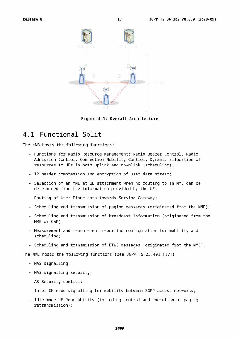
Figure 4.1-1: Functional Split between E-UTRAN and EPC
4.2 Interfaces
4.2.1 S1 Interface
4.2.2 X2 Interface
4.3 Radio Protocol architectureIn this subclause, the radio protocol architecture of E-UTRAN is given for the user plane and the control plane.
4.3.1 User planeThe figure below shows the protocol stack for the user-plane, where PDCP, RLC and MAC sublayers (terminated in eNB on the network side) perform the functions listed for the user plane in subclause 6, e.g. header compression, ciphering, scheduling, ARQ and HARQ;
3GPP
3GPP TS 36.300 V8.6.0 (2008-09)17Release 8
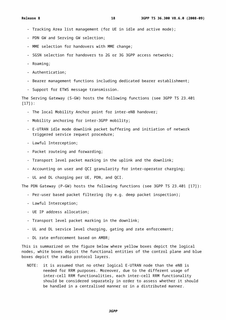
Figure 4.3.1-1: User-plane protocol stack
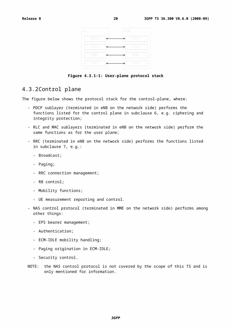
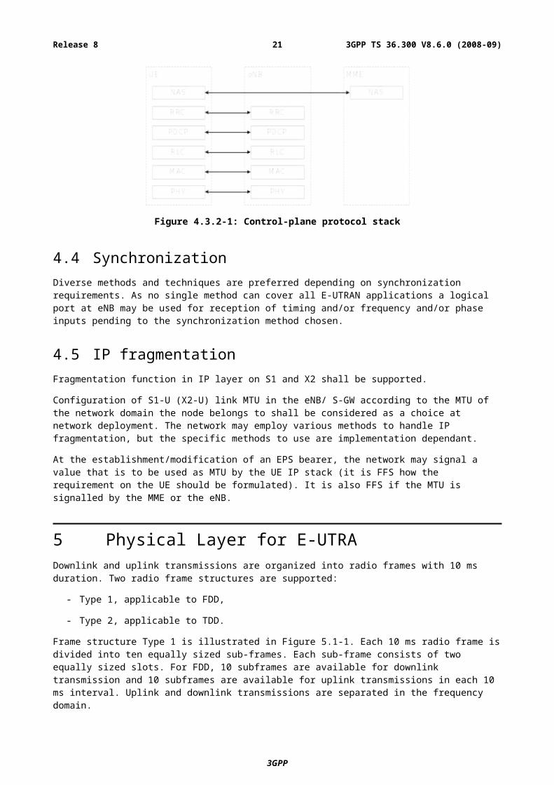
4.3.2 Control planeThe figure below shows the protocol stack for the control-plane, where:
- PDCP sublayer (terminated in eNB on the network side) performs the functions listed for the control plane in subclause 6, e.g. ciphering and integrity protection;
- RLC and MAC sublayers (terminated in eNB on the network side) perform the same functions as for the user plane;
- RRC (terminated in eNB on the network side) performs the functions listed in subclause 7, e.g.:
- Broadcast;
- Paging;
- RRC connection management;
- RB control;
- Mobility functions;
- UE measurement reporting and control.
- NAS control protocol (terminated in MME on the network side) performs among other things:
- EPS bearer management;
- Authentication;
- ECM-IDLE mobility handling;
- Paging origination in ECM-IDLE;
- Security control.
NOTE: the NAS control protocol is not covered by the scope of this TS and is only mentioned for information.
3GPP
3GPP TS 36.300 V8.6.0 (2008-09)18Release 8
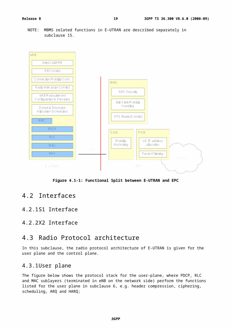
Figure 4.3.2-1: Control-plane protocol stack
4.4 SynchronizationDiverse methods and techniques are preferred depending on synchronization requirements. As no single method can cover all E-UTRAN applications a logical port at eNB may be used for reception of timing and/or frequency and/or phase inputs pending to the synchronization method chosen.
4.5 IP fragmentationFragmentation function in IP layer on S1 and X2 shall be supported.
Configuration of S1-U (X2-U) link MTU in the eNB/ S-GW according to the MTU of the network domain the node belongs to shall be considered as a choice at network deployment. The network may employ various methods to handle IP fragmentation, but the specific methods to use are implementation dependant.
At the establishment/modification of an EPS bearer, the network may signal a value that is to be used as MTU by the UE IP stack (it is FFS how the requirement on the UE should be formulated). It is also FFS if the MTU is signalled by the MME or the eNB.
5 Physical Layer for E-UTRADownlink and uplink transmissions are organized into radio frames with 10 ms duration. Two radio frame structures are supported:
- Type 1, applicable to FDD,
- Type 2, applicable to TDD.
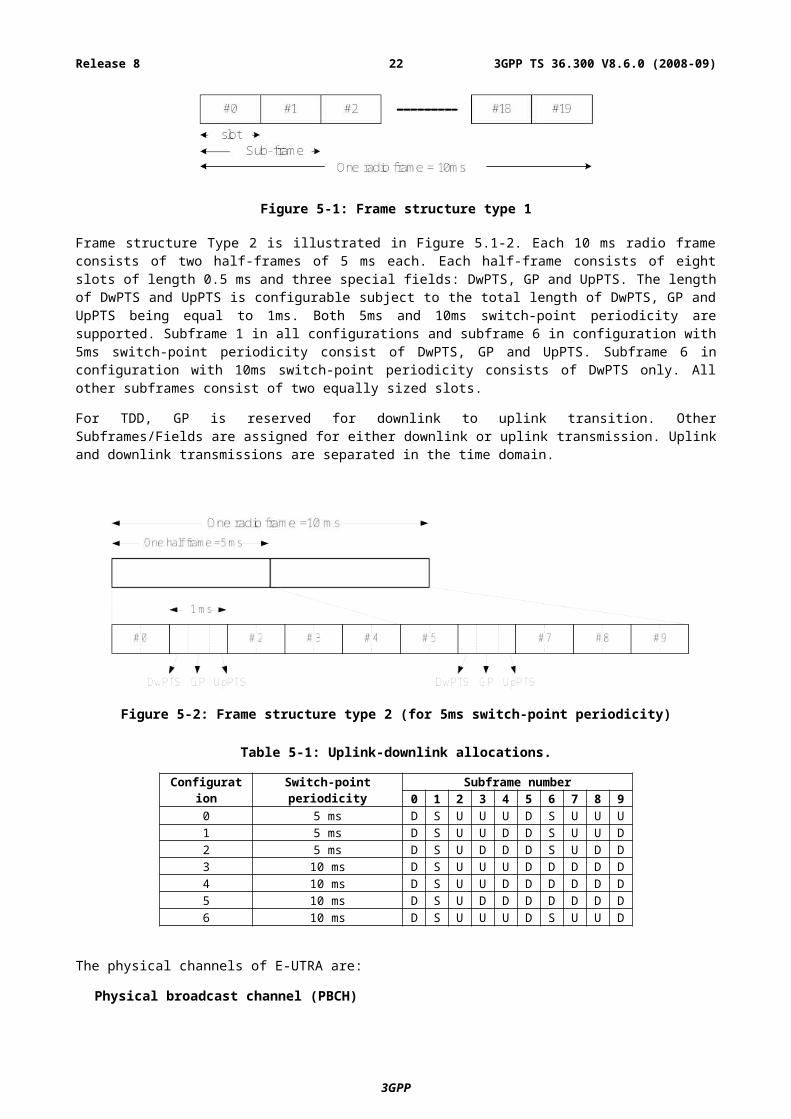
Frame structure Type 1 is illustrated in Figure 5.1-1. Each 10 ms radio frame is divided into ten equally sized sub-frames. Each sub-frame consists of two equally sized slots. For FDD, 10 subframes are available for downlink transmission and 10 subframes are available for uplink transmissions in each 10 ms interval. Uplink and downlink transmissions are separated in the frequency domain.
Figure 5-1: Frame structure type 1
Frame structure Type 2 is illustrated in Figure 5.1-2. Each 10 ms radio frame consists of two half-frames of 5 ms each. Each half-frame consists of eight slots of length 0.5 ms and three special fields: DwPTS, GP and UpPTS. The length of
3GPP
3GPP TS 36.300 V8.6.0 (2008-09)19Release 8
DwPTS and UpPTS is configurable subject to the total length of DwPTS, GP and UpPTS being equal to 1ms. Both 5ms and 10ms switch-point periodicity are supported. Subframe 1 in all configurations and subframe 6 in configuration with 5ms switch-point periodicity consist of DwPTS, GP and UpPTS. Subframe 6 in configuration with 10ms switch-point periodicity consists of DwPTS only. All other subframes consist of two equally sized slots.
For TDD, GP is reserved for downlink to uplink transition. Other Subframes/Fields are assigned for either downlink or uplink transmission. Uplink and downlink transmissions are separated in the time domain.
Figure 5-2: Frame structure type 2 (for 5ms switch-point periodicity)
Table 5-1: Uplink-downlink allocations.
Configuration
Switch-point periodicity Subframe number0 1 2 3 4 5 6 7 8 9
0 5 ms D S U U U D S U U U1 5 ms D S U U D D S U U D2 5 ms D S U D D D S U D D3 10 ms D S U U U D D D D D4 10 ms D S U U D D D D D D5 10 ms D S U D D D D D D D6 10 ms D S U U U D S U U D
The physical channels of E-UTRA are:
Physical broadcast channel (PBCH)
- The coded BCH transport block is mapped to four subframes within a 40 ms interval;
- 40 ms timing is blindly detected, i.e. there is no explicit signalling indicating 40 ms timing;
- Each subframe is assumed to be self-decodable, i.e. the BCH can be decoded from a single reception, assuming sufficiently good channel conditions.
Physical control format indicator channel (PCFICH)
- Informs the UE about the number of OFDM symbols used for the PDCCHs;
- Transmitted in every subframe.
Physical downlink control channel (PDCCH)
- Informs the UE about the resource allocation of PCH and DL-SCH, and Hybrid ARQ information related to DL-SCH;
- Carries the uplink scheduling grant.
Physical Hybrid ARQ Indicator Channel (PHICH)
- Carries Hybrid ARQ ACK/NAKs in response to uplink transmissions.
3GPP
3GPP TS 36.300 V8.6.0 (2008-09)20Release 8
Physical downlink shared channel (PDSCH)
- Carries the DL-SCH and PCH.
Physical multicast channel (PMCH)
- Carries the MCH.
Physical uplink control channel (PUCCH)
- Carries Hybrid ARQ ACK/NAKs in response to downlink transmission;
- Carries Scheduling Request (SR);
- Carries CQI reports.
Physical uplink shared channel (PUSCH)
- Carries the UL-SCH.
Physical random access channel (PRACH)
- Carries the random access preamble.
5.1 Downlink Transmission Scheme
5.1.1 Basic transmission scheme based on OFDMThe downlink transmission scheme is based on conventional OFDM using a cyclic prefix. The OFDM sub-carrier spacing is f = 15 kHz. 12 consecutive sub-carriers during one slot correspond to one downlink resource block. In the frequency domain, the number of resource blocks, NRB, can range from NRB-min = 6 to NRB-max = [110].
In addition there is also a reduced sub-carrier spacingflow = 7.5 kHz, only for MBMS-dedicated cell.
In the case of 15 kHz sub-carrier spacing there are two cyclic-prefix lengths, corresponding to seven and six OFDM symbols per slot respectively.
- Normal cyclic prefix: TCP = 160Ts (OFDM symbol #0) , TCP = 144Ts (OFDM symbol #1 to #6)
- Extended cyclic prefix: TCP-e = 512Ts (OFDM symbol #0 to OFDM symbol #5)
where Ts = 1/ (2048 f)
In case of 7.5 kHz sub-carrier spacing, there is only a single cyclic prefix length TCP-low = 1024Ts, corresponding to 3 OFDM symbols per slot.
In case of FDD, operation with half duplex from UE point of view is supported.
5.1.2 Physical-layer processingThe downlink physical-layer processing of transport channels consists of the following steps:
- CRC insertion: 24 bit CRC is the baseline for PDSCH;
- Channel coding: Turbo coding based on QPP inner interleaving with trellis termination;
- Physical-layer hybrid-ARQ processing;
- Channel interleaving;
- Scrambling: transport-channel specific scrambling on DL-SCH, BCH, and PCH. Common MCH scrambling for all cells involved in a specific MBSFN transmission;
- Modulation: QPSK, 16QAM, and 64QAM;
3GPP
3GPP TS 36.300 V8.6.0 (2008-09)21Release 8
- Layer mapping and pre-coding;
- Mapping to assigned resources and antenna ports.
5.1.3 Physical downlink control channelThe downlink control signalling (PDCCH) is located in the first n OFDM symbols where n 3 and consists of:
- Transport format and resource allocation related to DL-SCH and PCH, and hybrid ARQ information related to DL-SCH;
- Transport format, resource allocation, and hybrid-ARQ information related to UL-SCH;
Transmission of control signalling from these groups is mutually independent.
Multiple physical downlink control channels are supported and a UE monitors a set of control channels.
Control channels are formed by aggregation of control channel elements, each control channel element consisting of a set of resource elements. Different code rates for the control channels are realized by aggregating different numbers of control channel elements.
QPSK modulation is used for all control channels.
Each separate control channel has its own set of x-RNTI.
There is an implicit relation between the uplink resources used for dynamically scheduled data transmission, or the DL control channel used for assignment, and the downlink ACK/NAK resource used for feedback
5.1.4 Downlink Reference signalThe downlink reference signals consist of known reference symbols inserted in the first and third last OFDM symbol of each slot. There is one reference signal transmitted per downlink antenna port. The number of downlink antenna ports equals 1, 2, or 4. The two-dimensional reference signal sequence is generated as the symbol-by-symbol product of a two-dimensional orthogonal sequence and a two-dimensional pseudo-random sequence. There are 3 different two-dimensional orthogonal sequences and 170 different two-dimensional pseudo-random sequences. Each cell identity corresponds to a unique combination of one orthogonal sequence and one pseudo-random sequence, thus allowing for 510 unique cell identities 170 cell identity groups with 3 cell identities in each group).
Frequency hopping can be applied to the downlink reference signals. The frequency hopping pattern has a period of one frame (10 ms). Each frequency hopping pattern corresponds to one cell identity group.
The downlink MBSFN reference signals consist of known reference symbols inserted every other sub-carrier in the 3rd, 7th and 11th OFDM symbol of sub-frame in case of 15kHz sub-carrier spacing and extended cyclic prefix
5.1.5 Downlink multi-antenna transmissionMulti-antenna transmission with 2 and 4 transmit antennas is supported. The maximum number of codeword is two irrespective to the number of antennas with fixed mapping between code words to layers.
Spatial division multiplexing (SDM) of multiple modulation symbol streams to a single UE using the same time-frequency (-code) resource, also referred to as Single-User MIMO (SU-MIMO) is supported. When a MIMO channel is solely assigned to a single UE, it is known as SU-MIMO. Spatial division multiplexing of modulation symbol streams to different UEs using the same time-frequency resource, also referred to as MU-MIMO, is also supported. There is semi-static switching between SU-MIMO and MU-MIMO per UE.
In addition, the following techniques are supported:
- Code-book-based pre-coding with a single pre-coding feedback per full system bandwidth when the system bandwidth (or subset of resource blocks) is smaller or equal to12RB and per 5 adjacent resource blocks or the full system bandwidth (or subset of resource blocks) when the system bandwidth is larger than 12RB.
- Rank adaptation with single rank feedback referring to full system bandwidth. Node B can override rank report.
3GPP
3GPP TS 36.300 V8.6.0 (2008-09)22Release 8

5.1.6 MBSFN transmissionMBSFN is supported for the MCH transport channel. Multiplexing of transport channels using MBSFN and non-MBSFN transmission is done on a per-sub-frame basis. Additional reference symbols, transmitted using MBSFN are transmitted within MBSFN subframes.
5.1.7 Physical layer procedure
5.1.7.1 Link adaptation
Link adaptation (AMC: adaptive modulation and coding) with various modulation schemes and channel coding rates is applied to the shared data channel. The same coding and modulation is applied to all groups of resource blocks belonging to the same L2 PDU scheduled to one user within one TTI and within a single stream.
5.1.7.2 Power Control
Downlink power control can be used.
5.1.7.3 Cell search
Cell search is the procedure by which a UE acquires time and frequency synchronization with a cell and detects the Cell ID of that cell. E-UTRA cell search supports a scalable overall transmission bandwidth corresponding to 72 sub-carriers and upwards.
E-UTRA cell search is based on following signals transmitted in the downlink: the primary and secondary synchronization signals, the downlink reference signals.
The primary and secondary synchronization signals are transmitted over the centre 72 sub-carriers in the first and sixth subframe of each frame.
Neighbour-cell search is based on the same downlink signals as initial cell search.
5.1.8 Physical layer measurements definition The physical layer measurements to support mobility are classified as:
- within E-UTRAN (intra-frequency, inter-frequency);
- between E-UTRAN and GERAN/UTRAN (inter-RAT);
- between E-UTRAN and non-3GPP RAT (Inter 3GPP access system mobility).
For measurements within E-UTRAN at least two basic UE measurement quantities shall be supported:
- Reference symbol received power (RSRP);
- E-UTRA carrier received signal strength indicator (RSSI).
5.2 Uplink Transmission Scheme
5.2.1 Basic transmission schemeFor both FDD and TDD, the uplink transmission scheme is based on single-carrier FDMA, more specifically DFTS-OFDM.
3GPP
3GPP TS 36.300 V8.6.0 (2008-09)23Release 8
Figure 5.2.1-1: Transmitter scheme of SC-FDMA
The uplink sub-carrier spacing f = 15 kHz. The sub-carriers are grouped into sets of 12 consecutive sub-carriers, corresponding to the uplink resource blocks. 12 consecutive sub-carriers during one slot correspond to one uplink resource block. In the frequency domain, the number of resource blocks, NRB, can range from NRB-min = 6 to NRB-max = [110].
There are two cyclic-prefix lengths defined: Normal cyclic prefix and extended cyclic prefix corresponding to seven and six SC-FDMA symbol per slot respectively.
- Normal cyclic prefix: TCP = 160Ts (SC-FDMA symbol #0) , TCP = 144Ts (SC-FDMA symbol #1 to #6)
- Extended cyclic prefix: TCP-e = 512Ts (SC-FDMA symbol #0 to SC-FDMA symbol #5)
5.2.2 Physical-layer processingThe uplink physical layer processing of transport channels consists of the following steps:
- CRC insertion: 24 bit CRC is the baseline for PUSCH;
- Channel coding: turbo coding based on QPP inner interleaving with trellis termination;
- Physical-layer hybrid-ARQ processing;
- Scrambling: UE-specific scrambling;
- Modulation: QPSK, 16QAM, and 64QAM (64 QAM optional in UE);
- Mapping to assigned resources [and antennas].
5.2.3 Physical uplink control channelThe PUCCH shall be mapped to a control channel resource in the uplink. A control channel resource is defined by a code and two resource blocks, consecutive in time, with hopping at the slot boundary.
Depending on presence or absence of uplink timing synchronization, the uplink physical control signalling can differ.
In the case of time synchronization being present, the outband control signalling consists of:
- CQI;
- ACK/NAK;
- Scheduling Request (SR).
The CQI informs the scheduler about the current channel conditions as seen by the UE. If MIMO transmission is used, the CQI includes necessary MIMO-related feedback.
The HARQ feedback in response to downlink data transmission consists of a single ACK/NAK bit per HARQ process.
PUCCH resources for SR and CQI reporting are assigned and can be revoked through RRC signalling. An SR is not necessarily assigned to UEs acquiring synchronization through the RACH (i.e. synchronised UEs may or may not have a dedicated SR channel). PUCCH resources for SR and CQI are lost when the UE is no longer synchronized.
3GPP
3GPP TS 36.300 V8.6.0 (2008-09)24Release 8
5.2.4 Uplink Reference signalUplink reference signals [for channel estimation for coherent demodulation] are transmitted in the 4-th block of the slot [assumed normal CP]. The uplink reference signals sequence length equals the size (number of sub-carriers) of the assigned resource.
The uplink reference signals are based on [prime-length] Zadoff-chu sequences that are either truncated or cyclically extended to the desired length
Multiple reference signals can be created:
- Based on different Zadoff-Chu sequence from the same set of Zadoff-Chu sequences;
- Different shifts of the same sequence.
5.2.5 Random access preambleThe physical layer random access burst consists of a cyclic prefix, a preamble, and a guard time during which nothing is transmitted.
The random access preambles are generated from Zadoff-Chu sequences with zero correlation zone, ZC-ZCZ, generated from one or several root Zadoff-Chu sequences.
5.2.6 Uplink multi-antenna transmissionThe baseline antenna configuration for uplink MIMO is MU-MIMO. To allow for MU-MIMO reception at the Node B, allocation of the same time and frequency resource to several UEs, each of which transmitting on a single antenna, is supported.
Closed loop type adaptive antenna selection transmit diversity shall be supported for FDD (optional in UE).
5.2.7 Physical channel procedure
5.2.7.1 Link adaptation
Uplink link adaptation is used in order to guarantee the required minimum transmission performance of each UE such as the user data rate, packet error rate, and latency, while maximizing the system throughput.
Three types of link adaptation are performed according to the channel conditions, the UE capability such as the maximum transmission power and maximum transmission bandwidth etc., and the required QoS such as the data rate, latency, and packet error rate etc. Three link adaptation methods are as follows.
- Adaptive transmission bandwidth;
- Transmission power control;
- Adaptive modulation and channel coding rate.
5.2.7.2 Uplink Power control
Intra-cell power control: the power spectral density of the uplink transmissions can be influenced by the eNB.
5.2.7.3 Uplink timing control
The timing advance is derived from the UL received timing and sent by the eNB to the UE which the UE uses to advance/delay its timings of transmissions to the eNB so as to compensate for propagation delay and thus time align the transmissions from different UEs with the receiver window of the eNB.
The timing advance command is on a per need basis with a granularity in the step size of 0.52 s (16Ts).
3GPP
3GPP TS 36.300 V8.6.0 (2008-09)25Release 8
5.3 Transport ChannelsThe physical layer offers information transfer services to MAC and higher layers. The physical layer transport services are described by how and with what characteristics data are transferred over the radio interface. An adequate term for this is “Transport Channel”.
NOTE: This should be clearly separated from the classification of what is transported, which relates to the concept of logical channels at MAC sublayer.
Downlink transport channel types are:
1. Broadcast Channel (BCH) characterised by:
- fixed, pre-defined transport format;
- requirement to be broadcast in the entire coverage area of the cell.
2. Downlink Shared Channel (DL-SCH) characterised by:
- support for HARQ;
- support for dynamic link adaptation by varying the modulation, coding and transmit power;
- possibility to be broadcast in the entire cell;
- possibility to use beamforming;
- support for both dynamic and semi-static resource allocation;
- support for UE discontinuous reception (DRX) to enable UE power saving;
- support for MBMS transmission.
NOTE: the possibility to use slow power control depends on the physical layer.
3. Paging Channel (PCH) characterised by:
- support for UE discontinuous reception (DRX) to enable UE power saving (DRX cycle is indicated by the network to the UE);
- requirement to be broadcast in the entire coverage area of the cell;
- mapped to physical resources which can be used dynamically also for traffic/other control channels.
4. Multicast Channel (MCH) characterised by:
- requirement to be broadcast in the entire coverage area of the cell;
- support for MBSFN combining of MBMS transmission on multiple cells;
- support for semi-static resource allocation e.g. with a time frame of a long cyclic prefix.
Uplink transport channel types are:
1. Uplink Shared Channel (UL-SCH) characterised by:
- possibility to use beamforming; (likely no impact on specifications)
- support for dynamic link adaptation by varying the transmit power and potentially modulation and coding;
- support for HARQ;
- support for both dynamic and semi-static resource allocation.
NOTE: the possibility to use uplink synchronisation and timing advance depend on the physical layer.
2. Random Access Channel(s) (RACH) characterised by:
3GPP
3GPP TS 36.300 V8.6.0 (2008-09)26Release 8
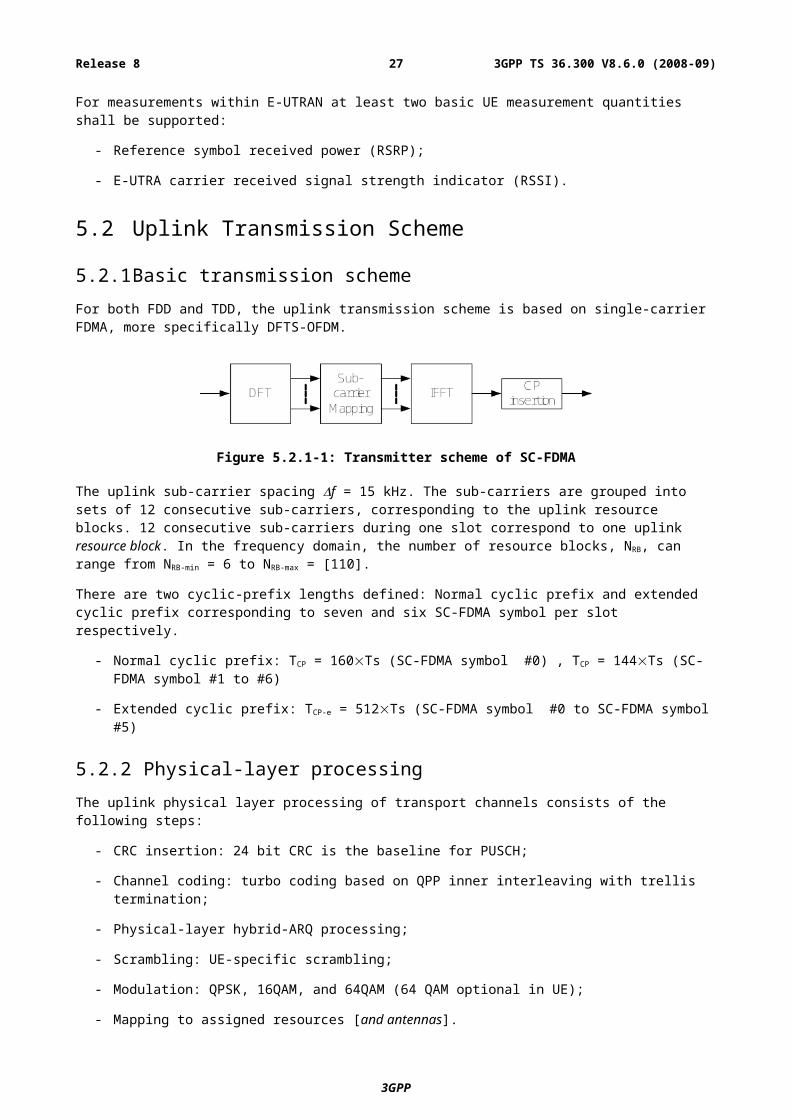
- limited control information;
- collision risk;
NOTE: the possibility to use open loop power control depends on the physical layer solution.
5.3.1 Mapping between transport channels and physical channelsThe figures below depict the mapping between transport and physical channels:
Figure 5.3.1-1: Mapping between downlink transport channels and downlink physical channels
Figure 5.3.1-2: Mapping between uplink transport channels and uplink physical channels
5.4 E-UTRA physical layer modelThe E-UTRAN physical layer model is captured in TS 36.302 [9].
5.4.1 Void
5.4.2 Void
6 Layer 2Layer 2 is split into the following sublayers: Medium Access Control (MAC), Radio Link Control (RLC) and Packet Data Convergence Protocol (PDCP).
This subclause gives a high level description of the Layer 2 sub-layers in terms of services and functions. The two figures below depict the PDCP/RLC/MAC architecture for downlink and uplink, where:
3GPP
3GPP TS 36.300 V8.6.0 (2008-09)27Release 8
- Service Access Points (SAP) for peer-to-peer communication are marked with circles at the interface between sublayers. The SAP between the physical layer and the MAC sublayer provides the transport channels. The SAPs between the MAC sublayer and the RLC sublayer provide the logical channels.
- The multiplexing of several logical channels (i.e. radio bearers) on the same transport channel (i.e. transport block) is performed by the MAC sublayer;
- In both uplink and downlink, only one transport block is generated per TTI in the non-MIMO case.
Figure 6-1: Layer 2 Structure for DL
3GPP
3GPP TS 36.300 V8.6.0 (2008-09)28Release 8
Figure 6-2: Layer 2 Structure for UL
6.1 MAC SublayerThis subclause provides an overview on services and functions provided by the MAC sublayer.
6.1.1 Services and FunctionsThe main services and functions of the MAC sublayer include:
- Mapping between logical channels and transport channels;
- Multiplexing/demultiplexing of RLC PDUs belonging to one or different radio bearers into/from transport blocks (TB) delivered to/from the physical layer on transport channels;
- Traffic volume measurement reporting;
- Error correction through HARQ;
- Priority handling between logical channels of one UE;
- Priority handling between UEs by means of dynamic scheduling;
- Transport format selection;
- Padding.
6.1.2 Logical ChannelsDifferent kinds of data transfer services as offered by MAC. Each logical channel type is defined by what type of information is transferred.
A general classification of logical channels is into two groups:
- Control Channels (for the transfer of control plane information);
- Traffic Channels (for the transfer of user plane information).
3GPP
3GPP TS 36.300 V8.6.0 (2008-09)29Release 8
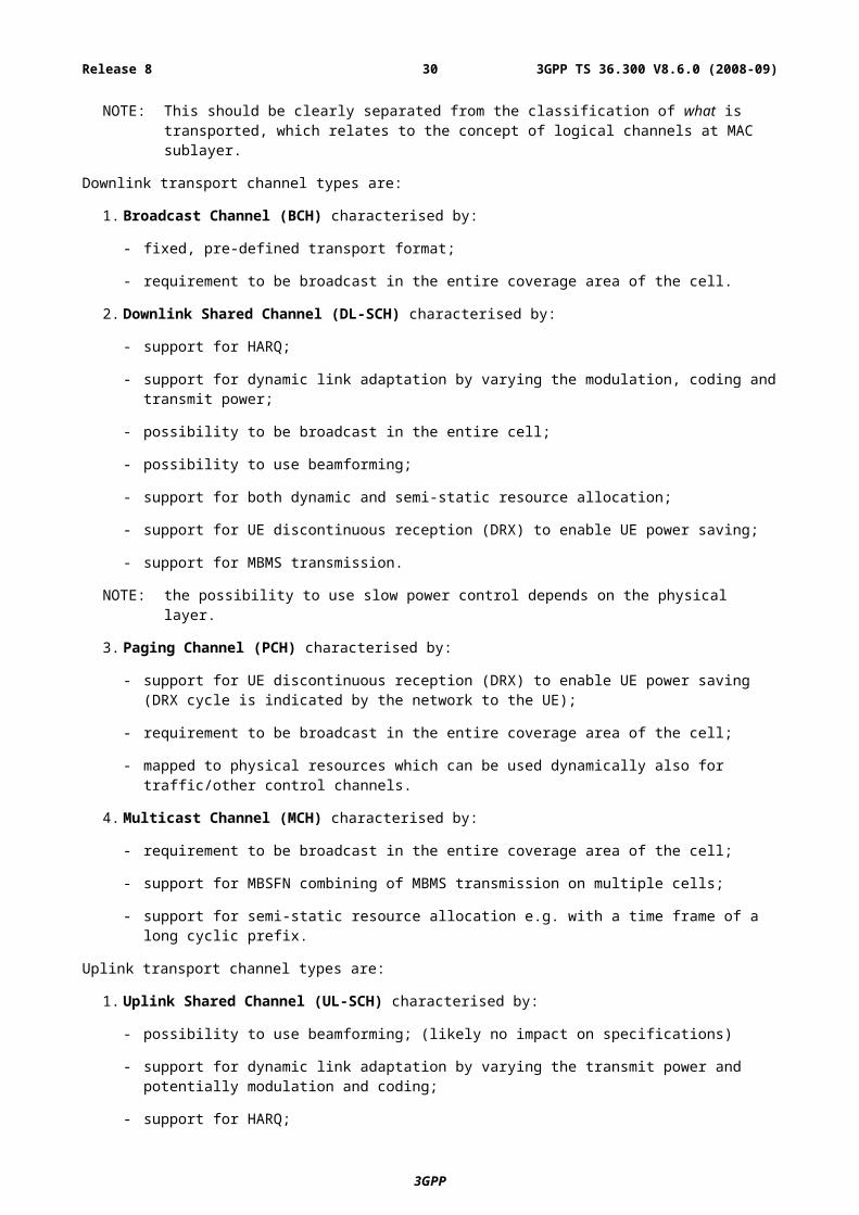
There is one MAC entity per cell. MAC generally consists of several function blocks (transmission scheduling functions, per UE functions, MBMS functions, MAC control functions, transport block generation…). Transparent Mode is only applied to BCCH, CCCH and PCCH.
6.1.2.1 Control Channels
Control channels are used for transfer of control plane information only. The control channels offered by MAC are:
- Broadcast Control Channel (BCCH)
A downlink channel for broadcasting system control information.
- Paging Control Channel (PCCH)
A downlink channel that transfers paging information and system information change notifications. This channel is used for paging when the network does not know the location cell of the UE.
- Common Control Channel (CCCH)
Channel for transmitting control information between UEs and network. This channel is used for UEs having no RRC connection with the network.
- Multicast Control Channel (MCCH)
A point-to-multipoint downlink channel used for transmitting MBMS control information from the network to the UE, for one or several MTCHs. This channel is only used by UEs that receive MBMS.
NOTE: It is FFS how MBMS scheduling is transmitted by either L2/3 signalling on MCCH or L1 signalling.
- Dedicated Control Channel (DCCH)
A point-to-point bi-directional channel that transmits dedicated control information between a UE and the network. Used by UEs having an RRC connection.
6.1.2.2 Traffic Channels
Traffic channels are used for the transfer of user plane information only. The traffic channels offered by MAC are:
- Dedicated Traffic Channel (DTCH)
A Dedicated Traffic Channel (DTCH) is a point-to-point channel, dedicated to one UE, for the transfer of user information. A DTCH can exist in both uplink and downlink.
- Multicast Traffic Channel (MTCH)
A point-to-multipoint downlink channel for transmitting traffic data from the network to the UE. This channel is only used by UEs that receive MBMS.
6.1.3 Mapping between logical channels and transport channels
6.1.3.1 Mapping in Uplink
The figure below depicts the mapping between uplink logical channels and uplink transport channels:
3GPP
3GPP TS 36.300 V8.6.0 (2008-09)30Release 8
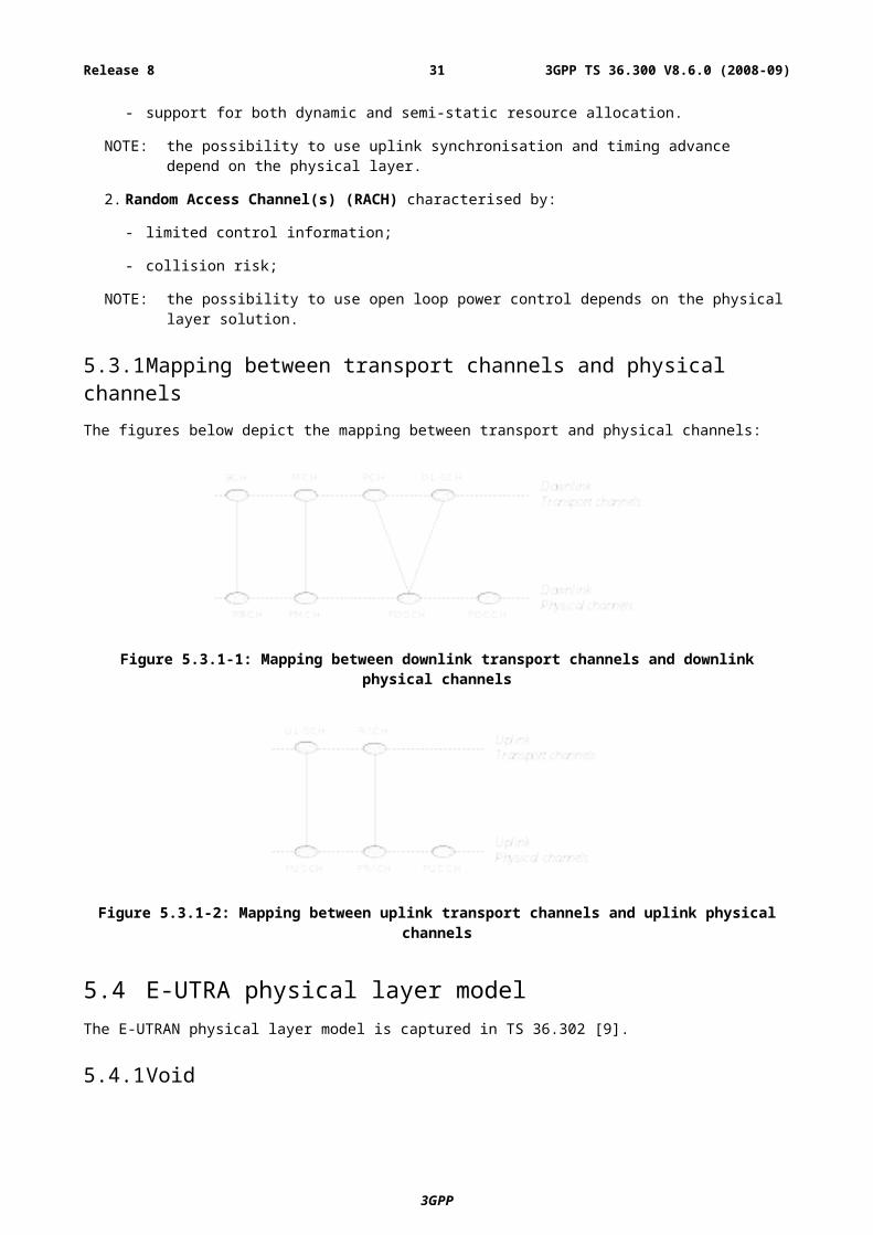
Figure 6.1.3.1-1: Mapping between uplink logical channels and uplink transport channels
In Uplink, the following connections between logical channels and transport channels exist:
- CCCH can be mapped to UL-SCH;
- DCCH can be mapped to UL- SCH;
- DTCH can be mapped to UL-SCH.
6.1.3.2 Mapping in Downlink
The figure below depicts the mapping between downlink logical channels and downlink transport channels:
Figure 6.1.3.2-1: Mapping between downlink logical channels and downlink transport channels
In Downlink, the following connections between logical channels and transport channels exist:
- BCCH can be mapped to BCH;
- BCCH can be mapped to DL-SCH;
- PCCH can be mapped to PCH;
- CCCH can be mapped to DL-SCH;
- DCCH can be mapped to DL-SCH;
- DTCH can be mapped to DL-SCH;
- MTCH can be mapped to DL-SCH;
- MTCH can be mapped to MCH;
- MCCH can be mapped to DL-SCH;
- MCCH can be mapped to MCH.
3GPP
3GPP TS 36.300 V8.6.0 (2008-09)31Release 8
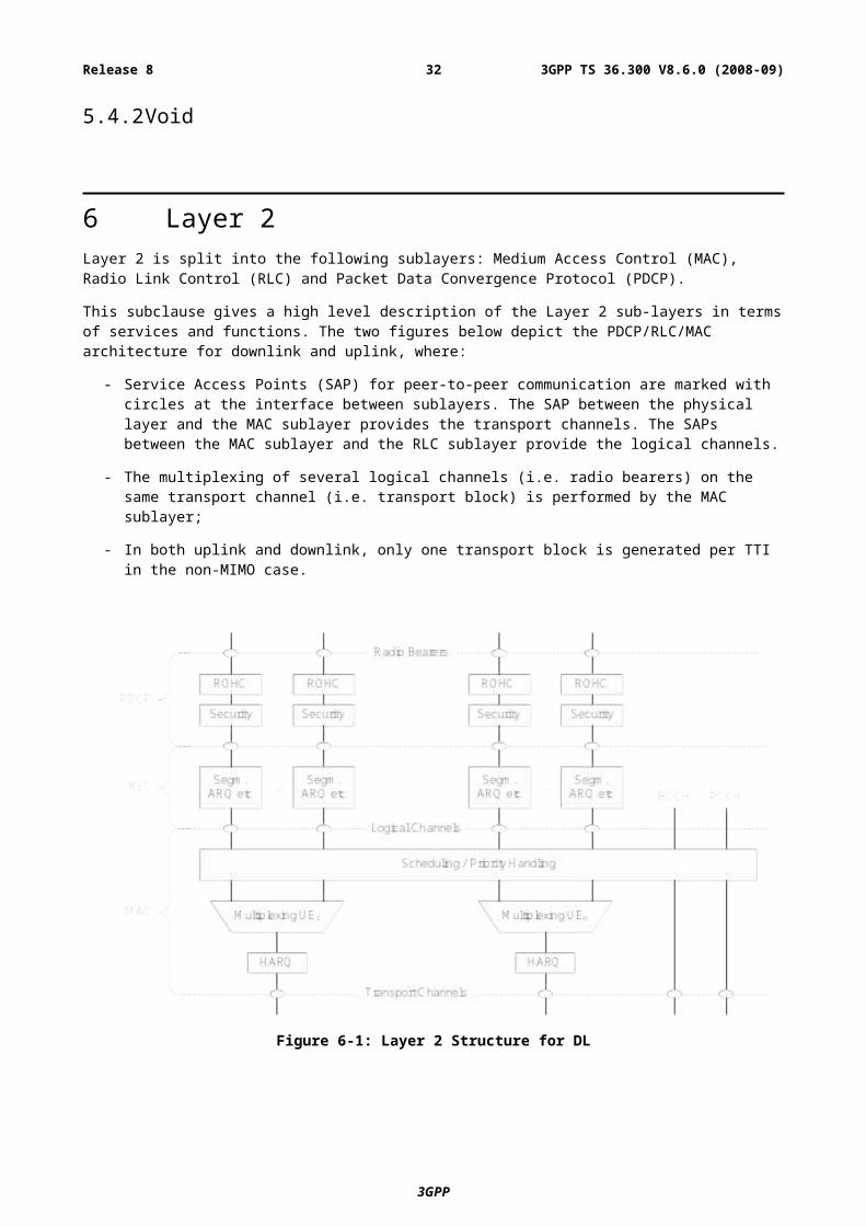
6.2 RLC SublayerThis subclause provides an overview on services, functions and PDU structure provided by the RLC sublayer. Note that:
- The reliability of RLC is configurable: some radio bearers may tolerate rare losses (e.g. TCP traffic);
- Radio Bearers are not characterized by a fixed sized data unit (e.g. a fixed sized RLC PDU).
6.2.1 Services and FunctionsThe main services and functions of the RLC sublayer include:
- Transfer of upper layer PDUs supporting AM or UM;
- TM data transfer;
- Error Correction through ARQ (CRC check provided by the physical layer, in other words no CRC needed at RLC level);
- Segmentation according to the size of the TB: only if an RLC SDU does not fit entirely into the TB then the RLC SDU is segmented into variable sized RLC PDUs, which do not include any padding;
- Re-segmentation of PDUs that need to be retransmitted: if a retransmitted PDU does not fit entirely into the new TB used for retransmission then the RLC PDU is re-segmented;
- The number of re-segmentations is not limited;
- Concatenation of SDUs for the same radio bearer;
- In-sequence delivery of upper layer PDUs except at HO;
- Duplicate Detection;
- Protocol error detection and recovery;
- SDU discard;
- Reset.
6.2.2 PDU StructureFigure 6.2.2-1 below depicts the RLC PDU structure where:
- The PDU sequence number carried by the RLC header is independent of the SDU sequence number (i.e. PDCP sequence number);
- A red dotted line indicates the occurrence of segmentation;
- Because segmentation only occurs when needed and concatenation is done in sequence, the content of an RLC PDU can generally be described by the following relations:
- {0; 1} last segment of SDUi + [0; n] complete SDUs + {0; 1} first segment of SDUi+n+1 ; or
- 1 segment of SDUi .
3GPP
3GPP TS 36.300 V8.6.0 (2008-09)32Release 8
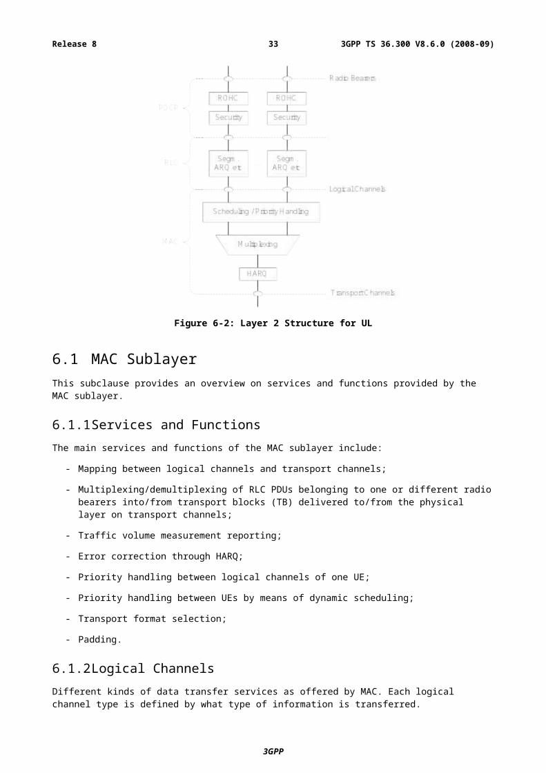
Figure 6.2.2-1: RLC PDU Structure
6.3 PDCP SublayerThis subclause provides an overview on services, functions and PDU structure provided by the PDCP sublayer.
6.3.1 Services and FunctionsThe main services and functions of the PDCP sublayer for the user plane include:
- Header compression and decompression: ROHC only;
- Transfer of user data: transmission of user data means that PDCP receives PDCP SDU from the NAS and forwards it to the RLC layer and vice versa;
- In-sequence delivery of upper layer PDUs at handover for RLC AM;
- Duplicate detection of lower layer SDUs at handover for RLC AM;
- Retransmission of PDCP SDUs at handover for RLC AM;
- Ciphering;
- Timer-based SDU discard in uplink.
NOTE: When compared to UTRAN, the lossless DL RLC PDU size change is not required.
The main services and functions of the PDCP for the control plane include:
- Ciphering and Integrity Protection;
- Transfer of control plane data: transmission of control plane data means that PDCP receives PDCP SDUs from RRC and forwards it to the RLC layer and vice versa.
6.3.2 PDU StructureFigure 6.3.2-1 below depicts the PDCP PDU structure where:
- PDCP PDU and PDCP header are octet-aligned;
- PDCP header can be either 1 or 2 bytes long.
3GPP
3GPP TS 36.300 V8.6.0 (2008-09)33Release 8
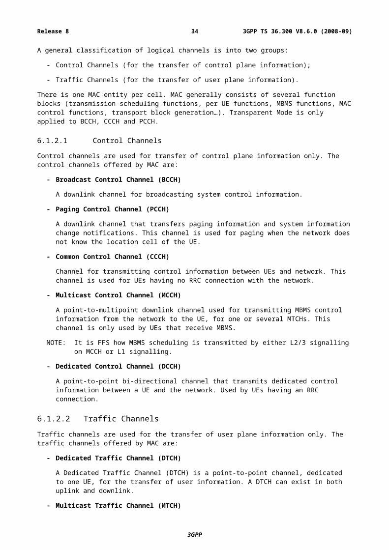
Figure 6.3.2-1: PDCP PDU Structure
6.4 Void
7 RRCThis subclause provides an overview on services and functions provided by the RRC sublayer.
7.1 Services and FunctionsThe main services and functions of the RRC sublayer include:
- Broadcast of System Information related to the non-access stratum (NAS);
- Broadcast of System Information related to the access stratum (AS);
- Paging;
- Establishment, maintenance and release of an RRC connection between the UE and E-UTRAN including:
- Allocation of temporary identifiers between UE and E-UTRAN;
- Configuration of signalling radio bearer(s) for RRC connection:
- Low priority SRB and high priority SRB.
- Security functions including key management;
- Establishment, configuration, maintenance and release of point to point Radio Bearers;
- Mobility functions including:
- UE measurement reporting and control of the reporting for inter-cell and inter-RAT mobility;
- Handover;
- UE cell selection and reselection and control of cell selection and reselection;
- Context transfer at handover.
- Notification for MBMS services;
- Establishment, configuration, maintenance and release of Radio Bearers for MBMS services;
- QoS management functions;
- UE measurement reporting and control of the reporting;
- NAS direct message transfer to/from NAS from/to UE.
7.2 RRC protocol states & state transitionsRRC uses the following states:
- RRC_IDLE:
3GPP
3GPP TS 36.300 V8.6.0 (2008-09)34Release 8
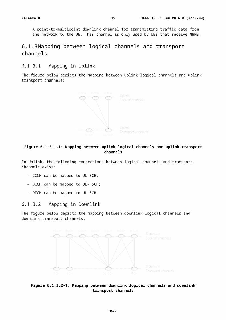
- PLMN selection;
- DRX configured by NAS (Option to have UE specific DRX is FFS);
- Broadcast of system information;
- Paging;
- Cell re-selection mobility;
- The UE shall have been allocated an id which uniquely identifies the UE in a tracking area;
- No RRC context stored in the eNB.
- RRC_CONNECTED:
- UE has an E-UTRAN-RRC connection;
- UE has context in E-UTRAN;
- E-UTRAN knows the cell which the UE belongs to;
- Network can transmit and/or receive data to/from UE;
- Network controlled mobility (handover and inter-RAT cell change order to GERAN with NACC);
- Neighbour cell measurements;
- At PDCP/RLC/MAC level:
- UE can transmit and/or receive data to/from network;
- UE monitors control signalling channel for shared data channel to see if any transmission over the shared data channel has been allocated to the UE;
- UE also reports channel quality information and feedback information to eNB;
- DRX period can be configured according to UE activity level for UE power saving and efficient resource utilization. This is under control of the eNB.
7.3 Transport of NAS messagesThe AS provides reliable in-sequence delivery of NAS messages in a cell. During handover, message loss or duplication of NAS messages can occur.
In E-UTRAN, NAS messages are either concatenated with RRC messages or carried in RRC without concatenation. Any dependent DL NAS message should always be concatenated with RRC messages for the bearer establishment/modification procedure. Concatenation of DL NAS with RRC message is not allowed otherwise. Concatenation of NAS messages with RRC messages is not supported for UL. Initial Direct Transfer is not used in E-UTRAN and no NAS message is concatenated with RRC connection request.
NOTE: NAS messages are integrity protected and ciphered by PDCP, in addition to the integrity protection and ciphering performed by NAS.
7.4 System InformationSystem information is divided into the MasterInformationBlock (MIB) and a number of SystemInformationBlocks (SIBs):
- MasterInformationBlock defines the most essential physical layer information of the cell required to receive further system information;
- SystemInformationBlockType1 contains information relevant when evaluating if a UE is allowed to access a cell and defines the scheduling of other system information blocks;
3GPP
3GPP TS 36.300 V8.6.0 (2008-09)35Release 8
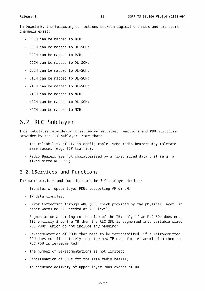
- SystemInformationBlockType2 contains common and shared channel information;
- SystemInformationBlockType3 contains cell re-selection information, mainly related to the serving cell;
- SystemInformationBlockType4 contains information about the serving frequency and intra-frequency neighbouring cells relevant for cell re-selection (including cell re-selection parameters common for a frequency as well as cell specific re-selection parameters);
- SystemInformationBlockType5 contains information about other E-UTRA frequencies and inter-frequency neighbouring cells relevant for cell re-selection (including cell re-selection parameters common for a frequency as well as cell specific re-selection parameters);
- SystemInformationBlockType6 contains information about UTRA frequencies and UTRA neighbouring cells relevant for cell re-selection (including cell re-selection parameters common for a frequency as well as cell specific re-selection parameters);
- SystemInformationBlockType7 contains information about GERAN frequencies relevant for cell re-selection (including cell re-selection parameters for each frequency);
- SystemInformationBlockType8 contains information about CDMA2000 frequencies and CDMA2000 neighbouring cells relevant for cell re-selection (including cell re-selection parameters common for a frequency as well as cell specific re-selection parameters);
- SystemInformationBlockType9 contains a home eNB identifier (HNBID).
The MIB is mapped on the BCCH and carried on BCH while all other SI messages are mapped on the BCCH and dynamically carried on DL-SCH where they can be identified through the SI-RNTI (System Information RNTI). Both the MIBand SystemInformationBlockType1use a fixed schedule with a periodicity of 40 and 80 ms respectively while the scheduling of other SI messages is flexible and indicated by SystemInformationBlockType1.
The eNB may schedule DL-SCH transmissions concerning logical channels other than BCCH in the same subframe as used for BCCH. The minimum UE capability restricts the BCCH mapped to DL-SCH e.g. regarding the maximum rate.
The Paging message is used to inform UEs in RRC_IDLE and UEs in RRC_CONNECTED about a system information change.
System information may also be provided to the UE by means of dedicated signalling e.g. upon handover.
7.5 Void
8 E-UTRAN identities
8.1 E-UTRAN related UE identitiesThe following E-UTRAN related UE identities are used:
a) C-RNTI:
- The C-RNTI provides a unique UE identification at the cell level identifying RRC Connection and used for scheduling;
b) Random value for contention resolution:
- During some transient states, the UE is temporarily identified with a random value for contention resolution purposes.
8.2 Network entity related IdentitiesThe following identities are used in E-UTRAN for identifying a specific network entity:
3GPP
3GPP TS 36.300 V8.6.0 (2008-09)36Release 8
a) MME identity:
- a UE in ECM-IDLE establishing an RRC connection has to provide a unique identification of its current MME to the eNB in order for the eNB to fetch the UE context from the MME;
- Within the S-TMSI, one field contains the identifier of the MME that allocated the S-TMSI. The identifier of MME is needed to ensure that the S-TMSI remains unique in a tracking area shared by multiple MMEs.
b) E-UTRAN Cell Global Identifier (ECGI)
- used to identify cells globally. The ECGI is constructed from the MCC (Mobile Country Code), MNC (Mobile Network Code) and the ECI (E-UTRAN Cell Identifier).
c) E-UTRAN Cell Identifier (ECI)
- used to identify cells within a PLMN. ECI has a length of 28 bits and contains the eNB Identifier.
d) Global eNB Identifier
- used to identify eNBs globally. The Global eNB Identifier is constructed from the MCC (Mobile Country Code), MNC (Mobile Network Code) and the eNB-Id (eNB Identifier).
e) eNB Identifier (eNB-Id)
- used to identify eNBs within a PLMN. The eNB Id is contained within the E-UTRAN Cell Identifier and can have the following lengths:
- short (20bits), which allows addressing of up to 256 cells per eNB- long (28bits), which allows addressing of one cell per eNB.
f) Tracking Area identity (TAI):
- This is the identity used to identify tracking areas. The Tracking Area Identity is constructed from the MCC (Mobile Country Code), MNC (Mobile Network Code) and TAC (Tracking Area Code).
The following identities are broadcast in every E-UTRAN cell:
a) E-UTRAN Cell Identifier:
- Uniquely identifying the cell within a PLMN.
b) Tracking Area identity:
- Tracking Area this cell belongs to.
c) One or more PLMNs:
- PLMN (s) for which this cell is providing radio access.
9 ARQ and HARQE-UTRAN provides ARQ and HARQ functionalities. The ARQ functionality provides error correction by retransmissions in acknowledged mode at Layer 2. The HARQ functionality ensures delivery between peer entities at Layer 1.
9.1 HARQ principlesThe HARQ within the MAC sublayer has the following characteristics:
- N-process Stop-And-Wait;
- HARQ transmits and retransmits transport blocks;
- In the downlink:
3GPP
3GPP TS 36.300 V8.6.0 (2008-09)37Release 8
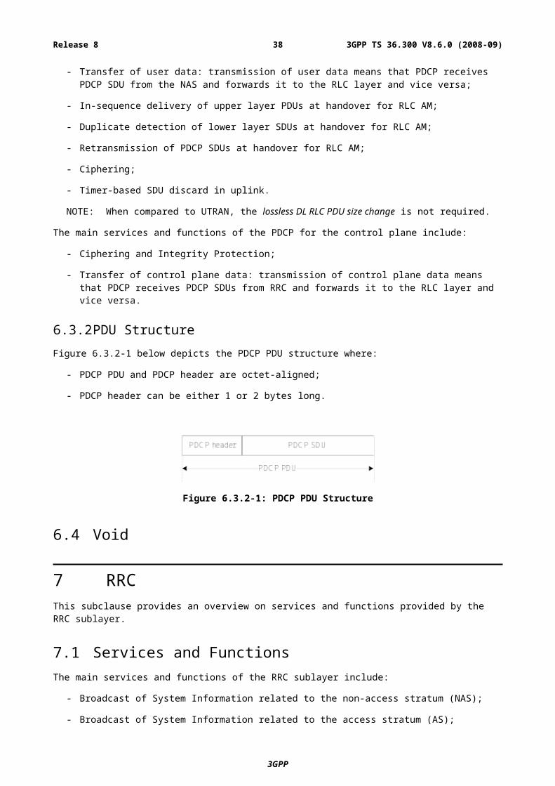
- Asynchronous adaptive HARQ;
- Uplink ACK/NAKs in response to downlink (re)transmissions are sent on PUCCH or PUSCH;
- PDCCH signals the HARQ process number and if it is a transmission or retransmission;
- Retransmissions are always scheduled through PDCCH.
- In the uplink:
- Synchronous HARQ;
- Maximum number of retransmissions configured per UE (as opposed to per radio bearer);
- Downlink ACK/NAKs in response to uplink (re)transmissions are sent on PHICH;
- HARQ operation in uplink is governed by the following principles (summarized in Table 9.1-1):
1) Regardless of the content of the HARQ feedback (ACK or NACK), when a PDCCH addressed to the C-RNTI of the UE is correctly received, the UE follows what the PDCCH asks the UE to do i.e. perform a transmission or a retransmission (referred to as adaptive retransmission);
2) When no PDCCH addressed to the C-RNTI of the UE is detected, the HARQ feedback dictates how the UE performs retransmissions:
- NACK: the UE performs a non-adaptive retransmission i.e. a retransmission on the same uplink resource as previously used by the same process;
- ACK: the UE does not perform any UL (re)transmission and keeps the data in the HARQ buffer. A PDCCH is then required to perform a retransmission i.e. a non-adaptive retransmission cannot follow.
- Measurement gaps are of higher priority than HARQ retransmissions: whenever an HARQ retransmission collides with a measurement gap, the HARQ retransmission does not take place.
Table 9.1-1: UL HARQ Operation
HARQ feedback seen by the UE
PDCCHseen by the UE UE behaviour
ACK or NACK New Transmission New transmission according to PDCCH
ACK or NACK Retransmission Retransmition according to PDCCH (adaptive retransmission)
ACK NoneNo (re)transmission, keep data in HARQ buffer and a PDDCH is required to resume retransmissions
NACK None Non-adaptive retransmission
9.2 ARQ principlesThe ARQ within the RLC sublayer has the following characteristics:
- ARQ retransmits RLC PDUs or RLC PDU segments;
- ARQ retransmissions are based on RLC status reports, and optionally can also be based on HARQ/ARQ interactions (see subclause 9.3).
- Polling for RLC status report is used when needed by RLC;
- Status reports can be triggered by upper layers.
3GPP
3GPP TS 36.300 V8.6.0 (2008-09)38Release 8
9.3 HARQ/ARQ interactionsIn HARQ assisted ARQ operation, ARQ uses knowledge obtained from the HARQ about the transmission status of a TB: if the HARQ transmitter detects a failed delivery of a TB due to e.g. maximum retransmission limit is reached, the relevant transmitting ARQ entities are notified and potential retransmissions and re-segmentation can be initiated.
10 MobilityLoad balancing is achieved in E-UTRAN with redirection mechanisms (upon RRC establishment, in RRC_CONNECTED and upon RRC release) and through the usage of inter-frequency and inter-RAT absolute priorities and inter-frequency Qoffset parameters.
Measurements to be performed by a UE for mobility are classified in at least three measurement types:
- Intra-frequency E-UTRAN measurements;
- Inter-frequency E-UTRAN measurements;
- Inter-RAT measurements for UTRAN and GERAN;
- Inter-RAT measurements of CDMA2000 HRPD or 1xRTT frequencies.
For each measurement type a measurement identity is used by E-UTRAN when configuring measurements as well as by the UE when reporting results of the measurements. Measurement quantities and reporting events are considered separately for each measurement type. Measurement commands are used by E-UTRAN to order the UE to start measurements, modify measurements or stop measurements. Three reporting criteria are used: event triggered reporting, periodic reporting and event triggered periodic reporting.
10.1 Intra E-UTRANIn E-UTRAN RRC_CONNECTED state, network-controlled UE-assisted handovers are performed and various DRX cycles are supported.
In E-UTRAN RRC_IDLE state, cell reselections are performed and DRX is supported.
10.1.1 Mobility Management in ECM-IDLE
10.1.1.1 Cell selection
The principles of PLMN selection in E-UTRA are based on the 3GPP PLMN selection principles. Cell selection is required on transition from EMM_DETACHED to EMM-REGISTERED and from ECM-IDLE or ECM-CONNECTED.
Cell selection:
- The UE NAS identifies a selected PLMN and equivalent PLMNs;
- The UE searches the E-UTRA frequency bands and for each carrier frequency identifies the strongest cell. It reads cell system information broadcast to identify its PLMN(s):
- The UE may search each carrier in turn (“initial cell selection”) or make use of stored information to shorten the search (“stored information cell selection”).
- The UE seeks to identify a suitable cell; if it is not able to identify a suitable cell it seeks to identify an acceptable cell. When a suitable cell is found or if only an acceptable cell is found it camps on that cell and commence the cell reselection procedure:
- A suitable cell is one for which the measured cell attributes satisfy the cell selection criteria; the cell PLMN is the selected PLMN, registered or an equivalent PLMN; the cell is not barred or reserved and the cell is not part of a tracking area which is in the list of “forbidden tracking areas for roaming”;
3GPP
3GPP TS 36.300 V8.6.0 (2008-09)39Release 8
- An acceptable cell is one for which the measured cell attributes satisfy the cell selection criteria and the cell is not barred;
Transition to RRC_IDLE:
On transition from RRC_CONNECTED to RRC_IDLE, a UE should camp on the last cell for which it was in RRC_CONNECTED or a cell/any cell of set of cells or frequency be assigned by RRC in the state transition message.
Recovery from out of coverage:
The UE should attempt to find a suitable cell in the manner described for stored information or initial cell selection above. If no suitable cell is found on any frequency or RAT the UE should attempt to find an acceptable cell.
10.1.1.2 Cell reselection
UE in RRC_IDLE performs cell reselection. The principles of the procedure are the following:
- The UE makes measurements of attributes of the serving and neighbour cells to enable the reselection process:
- There is no need to indicate neighbouring cell in the serving cell system information to enable the UE to search and measure a cell i.e. E-UTRAN relies on the UE to detect the neighbouring cells;
- For the search and measurement of inter-frequency neighbouring cells, only the carrier frequencies need to be indicated;
- Measurements may be omitted if the serving cell attribute fulfils particular search or measurement criteria.
- Cell reselection identifies the cell that the UE should camp on. It is based on cell reselection criteria which involves measurements of the serving and neighbour cells:
- Intra-frequency reselection is based on ranking of cells;
- Inter-frequency reselection is based on absolute priorities where UE tries to camp on highest priority frequency available. Absolute priorities for reselection are provided only by the RPLMN and valid only within the RPLMN; priorities are given by the system information and valid for all UEs in a cell, specific priorities per UE can be signalled in the RRC Connection Release message. A validity time can be associated with UE specific priorities.
- For inter-frequency neighbouring cells, it is possible to indicate layer-specific cell reselection parameters (e.g., layer specific offset). These parameters are common to all neighbouring cells on a frequency;
- An NCL can be provided by the serving cell to handle specific cases for intra- and inter-frequency neighbouring cells. This NCL contains cell specific cell reselection parameters (e.g., cell specific offset) for specific neighbouring cells;
- Black lists can be provided to prevent the UE from reselecting to specific intra- and inter-frequency neighbouring cells;
- Cell reselection can be speed dependent (speed detection based on UTRAN solution);
- Cell reselection parameters are applicable for all UEs in a cell, but it is possible to configure specific reselection parameters per UE group or per UE.
Cell access restrictions apply as for UTRAN, which consist of access class (AC) barring and cell reservation (e.g. for cells "reserved for operator use") applicable for mobiles in RRC_IDLE mode.
3GPP
3GPP TS 36.300 V8.6.0 (2008-09)40Release 8
10.1.1.3 Void
10.1.1.4 Void
10.1.1.5 Void
10.1.2 Mobility Management in ECM-CONNECTEDThe Intra-E-UTRAN-Access Mobility Support for UEs in ECM-CONNECTED handles all necessary steps for relocation/handover procedures, like processes that precede the final HO decision on the source network side (control and evaluation of UE and eNB measurements taking into account certain UE specific area restrictions), preparation of resources on the target network side, commanding the UE to the new radio resources and finally releasing resources on the (old) source network side. It contains mechanisms to transfer context data between evolved nodes, and to update node relations on C-plane and U-plane.
In E-UTRAN RRC_CONNECTED state, network-controlled UE-assisted handovers are performed and various DRX cycles are supported:
The UE makes measurements of attributes of the serving and neighbour cells to enable the process:
- There is no need to indicate neighbouring cell to enable the UE to search and measure a cell i.e. E-UTRAN relies on the UE to detect the neighbouring cells;
- For the search and measurement of inter-frequency neighbouring cells, at least the carrier frequencies need to be indicated;
- Network signals reporting criteria for event-triggered and periodical reporting;
- An NCL can be provided by the serving cell to handle specific cases for intra- and inter-frequency neighbouring cells. This NCL containa cell specific cell reselection parameters (e.g. cell specific offset) for specific neighbouring cells;
- Black lists can be provided to prevent the UE from measuring specific neighbouring cells.
Depending on whether the UE needs transmission/reception gaps to perform the relevant measurements, measurements are classified as gap assisted or non-gap assisted. A non-gap assisted measurement is a measurement on a cell that does not require transmission/reception gaps to allow the measurement to be performed. A gap assisted measurement is a measurement on a cell that does require transmission/reception gaps to allow the measurement to be performed. Gap patterns (as opposed to individual gaps) are configured and activated by RRC.
10.1.2.1 Handover
The intra E-UTRAN HO in RRC_CONNECTED state is UE assisted NW controlled HO, with HO preparation signalling in E-UTRAN:
- Part of the HO command comes from the target eNB and is transparently forwarded to the UE by the source eNB;
- To prepare the HO, the source eNB passes all necessary information to the target eNB (e.g. EPS bearer attributes and RRC context);
- - Both the source eNB and UE keep some context (e.g. C-RNTI) to enable the return of the UE in case of HO failure;
- UE accesses the target cell via RACH following a contention-free procedure using a dedicated RACH preamble or following a contention-based procedure if dedicated RACH preambles are not available:
- If an end-time is associated to the dedicated preamble, the UE follows a contention-based procedure after reaching the end time;
- If an end-time is not associated to the dedicated preamble, the UE uses the dedicated preamble until the handover procedure is finished (successfully or unsuccessfully);
3GPP
3GPP TS 36.300 V8.6.0 (2008-09)41Release 8
- If the RACH procedure towards the target cell is not successful within a certain time, the UE initiates radio link failure recovery using the best cell;
- No ROHC context is transferred at handover.
10.1.2.1.1 C-plane handling
The HO procedure is performed without EPC involvement, i.e. preparation messages are directly exchanged between the eNBs. The release of the resources at the source side during the HO completion phase is triggered by the eNB. The figure below depicts the basic handover scenario where neither MME nor Serving Gateway changes:
3GPP
3GPP TS 36.300 V8.6.0 (2008-09)42Release 8
Figure 10.1.2.1.1-1: Intra-MME/Serving Gateway HO
Below is a more detailed description of the intra-MME/Serving Gateway HO procedure:
0 The UE context within the source eNB contains information regarding roaming restrictions which where provided either at connection establishment or at the last TA update.
1 The source eNB configures the UE measurement procedures according to the area restriction information. Measurements provided by the source eNB may assist the function controlling the UE's connection mobility.
2 UE is triggered to send MEASUREMENT REPORT by the rules set by i.e. system information, specification etc.
3GPP
3GPP TS 36.300 V8.6.0 (2008-09)43Release 8
3 Source eNB makes decision based on MEASUREMENT REPORT and RRM information to hand off UE.
4 The source eNB issues a HANDOVER REQUEST message to the target eNB passing necessary information to prepare the HO at the target side (UE X2 signalling context reference at source eNB, UE S1 EPC signalling context reference, target cell ID, KeNB*, RRC context including the C-RNTI of the UE in the source eNB, AS-configuration (excluding physical layer configuration), EPS bearer context and physical layer ID of the source cell + MAC for possible RLF recovery). UE X2 / UE S1 signalling references enable the target eNB to address the source eNB and the EPC. The EPS bearer context includes necessary RNL and TNL addressing information, and QoS profiles of the EPS bearers.
5 Admission Control may be performed by the target eNB dependent on the received EPS bearer QoS information to increase the likelihood of a successful HO, if the resources can be granted by target eNB. The target eNB configures the required resources according to the received EPS bearer QoS information and reserves a C-RNTI and optionally a RACH preamble. The AS-configuration to be used in the target cell can either be specified independently (i.e. an "establishment") or as a delta compared to the AS-configuration used in the source cell (i.e. a "reconfiguration").
6 Target eNB prepares HO with L1/L2 and sends the HANDOVER REQUEST ACKNOWLEDGE to the source eNB. The HANDOVER REQUEST ACKNOWLEDGE message includes a transparent container to be sent to the UE as part of the Handover Command. The container includes a new C-RNTI, target eNB security algorithm identifiers for the selected security algorithms, may include a dedicated RACH preamble, indication of the expiry time of the dedicated RACH preamble, and possibly some other parameters i.e. access parameters, SIBs, etc. The HANDOVER REQUEST ACKNOWLEDGE message may also include RNL/TNL information for the forwarding tunnels, if necessary.
NOTE: As soon as the source eNB receives the HANDOVER REQUEST ACKNOWLEDGE, or as soon as the transmission of the handover command is initiated in the downlink, data forwarding may be initiated.
Steps 7 to 16 provide means to avoid data loss during HO and are further detailed in 10.1.2.1.2 and 10.1.2.3.
7 The source eNB generates the HANDOVER COMMAND (RRC message) towards the UE. The HANDOVER COMMAND includes the transparent container, which has been received from the target eNB. The source eNodeB performs the necessary integrity protection and ciphering of the message. The UE receives the HANDOVER COMMAND with necessary parameters (i.e. new C-RNTI, target eNB security algorithm identifiers, and optionally dedicated RACH preamble, possible expiry time of the dedicated RACH preamble, target eNB SIBs etc) and is commanded by the source eNB to perform the HO. The UE does not need to delay the handover execution for delivering the HARQ/ARQ responses to source eNB.
8 The source eNB sends the SN STATUS TRANSFER message to the target eNB to convey the uplink PDCP SN receiver status and the downlink PDCP SN transmitter status of SAE bearers for which PDCP status preservation applies (i.e. for RLC AM). The uplink PDCP SN receiver status includes at least the PDCP SN of the first missing UL SDU and may include a bit map of the receive status of the out of sequence UL SDUs that the UE needs to retransmit in the target cell, if there are any such SDUs. The downlink PDCP SN transmitter status indicates the next PDCP SN that the target eNB shall assign to new SDUs, not having a PDCP SN yet. The source eNB may omit sending this message if none of the SAE bearers of the UE shall be treated with PDCP status preservation.
9 After receiving the HANDOVER COMMAND, UE performs synchronisation to target eNB and accesses the target cell via RACH following a contention-free procedure if a dedicated RACH preamble was allocated in HANDOVER COMMAND or following a contention-based procedure if no dedicated preamble was allocated. UE derives target eNB specific keys and configures the selected security algorithms to be used in the target cell.
10 Network responds with UL allocation and timing advance.
11 When the UE has successfully accessed the target cell, the UE sends the HANDOVER CONFIRM message (C-RNTI) along with an uplink Buffer Status Report whenever possible to the target eNB to indicate that the handover procedure is completed for the UE. The target eNB verifies the C-RNTI sent in the HANDOVER CONFIRM message. The target eNB can now begin sending data to the UE.
12 The target eNB sends a PATH SWITCH message to MME to inform that the UE has changed cell.
13 The MME sends a USER PLANE UPDATE REQUEST message to the Serving Gateway.
3GPP
3GPP TS 36.300 V8.6.0 (2008-09)44Release 8
14 The Serving Gateway switches the downlink data path to the target side. The Serving gateway sends one or more "end marker" packets on the old path to the source eNB and then can release any U-plane/TNL resources towards the source eNB.
15 Serving Gateway sends a USER PLANE UPDATE RESPONSE message to MME.
16 The MME confirms the PATH SWITCH message with the PATH SWITCH ACK message.
17 By sending UE CONTEXT RELEASE the target eNB informs success of HO to source eNB and triggers the release of resources. The target eNB sends this message after the PATH SWITCH ACK message is received from the MME.
18 Upon reception of the UE CONTEXT RELEASE message, the source eNB can release radio and C-plane related resources associated to the UE context.
10.1.2.1.2 U-plane handling
The U-plane handling during the Intra-E-UTRAN-Access mobility activity for UEs in ECM-CONNECTED takes the following principles into account to avoid data loss during HO:
- During HO preparation U-plane tunnels can be established between the source eNB and the target eNB. There is one tunnel established for uplink data forwarding and another one for downlink data forwarding for each SAE bearer for which data forwarding is applied.
- During HO execution, user data can be forwarded from the source eNB to the target eNB. The forwarding may take place in a service and deployment dependent and implementation specific way.
- Forwarding of downlink user data from the source to the target eNB should take place in order as long as packets are received at the source eNB from the EPC or the source eNB buffer has not been emptied.
- During HO completion:
- The target eNB sends a PATH SWITCH message to MME to inform that the UE has gained access and MME sends a USER PLANE UPDATE REQUEST message to the Serving Gateway, the U-plane path is switched by the Serving Gateway from the source eNB to the target eNB.
- The source eNB should continue forwarding of U-plane data as long as packets are received at the source eNB from the Serving Gateway or the source eNB buffer has not been emptied.
For RLC-AM bearers:
- For in-sequence delivery and duplication avoidance, PDCP SN is maintained on a bearer basis and the source eNB informs the target eNB about the next DL PDCP SN to allocate to a packet which does not have a PDCP sequence number yet (either from source eNB or from the Serving Gateway).
- For security synchronisation, HFN is also maintained and the source eNB provides to the target one reference HFN for the UL and one for the DL i.e. HFN and corresponding SN.
- In both the UE and the target eNB, a window-based mechanism is needed for duplication detection.
- The occurrence of duplicates over the air interface in the target eNB is minimised by means of PDCP SN based reporting at the target eNB by the UE. In uplink, the reporting is optionally configured on a bearer basis by the eNB and the UE should first start by transmitting those reports when granted resources in the target eNB. In downlink, the eNB is free to decide when and for which bearers a report is sent and the UE does not wait for the report to resume uplink transmission.
- The target eNB re-transmits and prioritizes all downlink PDCP SDUs forwarded by the source eNB (i.e. the target eNB should send data with PDCP SNs from X2 before sending data from S1), with the exception of PDCP SDUs of which the reception was acknowledged through PDCP SN based reporting by the UE.
- The UE re-transmits in the target eNB all uplink PDCP SDUs starting from the first PDCP SDU following the last consecutively confirmed PDCP SDU i.e. the oldest PDCP SDU that has not been acknowledged at RLC in the source, excluding the PDCP SDUs of which the reception was acknowledged through PDCP SN based reporting by the target.
3GPP
3GPP TS 36.300 V8.6.0 (2008-09)45Release 8
For RLC-UM bearers:
- The PDCP SN and HFN are reset in the target eNB.
- No PDCP SDUs are retransmitted in the target eNB.
- The target eNB prioritize all downlink PDCP SDUs forwarded by the source eNB if any (i.e. the target eNB should send data with PDCP SNs from X2 before sending data from S1),.
- The UE PDCP entity does not attempt to retransmit any PDCP SDU in the target cell for which transmission had been completed in the source cell. Instead UE PDCP entity starts the transmission with other PDCP SDUs.
10.1.2.2 Path Switch
After the downlink path is switched at the Serving GW downlink packets on the forwarding path and on the new direct path may arrive interchanged at the target eNB. The target eNodeB should first deliver all forwarded packets to the UE before delivering any of the packets received on the new direct path. The method employed in the target eNB to enforce the correct delivery order of packets is outside the scope of the standard.
In order to assist the reordering function in the target eNB, the Serving GW shall send one or more "end marker" packets on the old path immediately after switching the path for each SAE bearer of the UE. The "end marker" packet shall not contain user data. The "end marker" is indicated in the GTP header. After completing the sending of the tagged packets the GW shall not send any further user data packets via the old path.
Upon receiving the "end marker" packets, the source eNB shall, if forwarding is activated for that bearer, forward the packet toward the target eNB.
On detection of an "end marker" the target eNB shall discard the end marker packet and initiate any necessary processing to maintain in sequence delivery of user data forwarded over X2 interface and user data received from the serving GW over S1 as a result of the path switch.
10.1.2.3 Data forwarding
10.1.2.3.1 For RLC-AM bearers
Upon handover, the source eNB forwards in order to the target eNB all downlink PDCP SDUs with their SN that have not been acknowledged by the UE. In addition, the source eNB may forward without a PDCP SN fresh data arriving over S1 to the target eNB. In addition, the source eNB may forward fresh data arriving over S1 to the target eNB.
NOTE: Target eNB does not have to wait for the completion of forwarding from the source eNB before it begins transmitting packets to the UE.
The source eNB discards any remaining downlink RLC PDUs. Correspondingly, the source eNB does not forward the downlink RLC context to the target eNB.
NOTE: Source eNB does not need to abort on going RLC transmissions with the UE as it starts data forwarding to the target eNB.
Upon handover, the source eNB forwards uplink PDCP SDUs successfully received in-sequence to the Serving Gateway, may forward uplink PDCP SDUs with their SN received out-of-sequence to the target eNB and shall discard any remaining uplink RLC PDUs. Correspondingly, the source eNB does not forward the uplink RLC context to the target eNB.
The PDCP SN of forwarded SDUs is carried in the "PDCP PDU number" field of the GTP-U extension header. The target eNB shall use the PDCP SN if it is available in the forwarded GTP-U packet.
In-sequence delivery of upper layer PDUs during handover is based on a continuous PDCP SN and is provided by the re-ordering function at the PDCP layer, which can be activated at least during inter-eNB mobility:
- in the downlink, the re-ordering function at the UE PDCP layer guarantees in-sequence delivery of downlink PDCP SDUs;
- in the uplink, the re-ordering function at the target eNB PDCP layer guarantees in-sequence delivery of uplink PDCP SDUs.
3GPP
3GPP TS 36.300 V8.6.0 (2008-09)46Release 8
After handover, when the UE receives a PDCP SDU from the target eNB, it can deliver it to higher layer together with all PDCP SDUs with lower SNs regardless of possible gaps.
10.1.2.3.2 For RLC-UM bearers
Upon handover, the source eNB does not forward to the target eNB downlink PDCP SDUs for which transmission had been completed in the source cell. PDCP SDUs that have not been transmitted may be forwarded. In addition, the source eNB may forward fresh data arriving over S1 to the target eNB. The source eNB discards any remaining downlink RLC PDUs. Correspondingly, the source eNB does not forward the downlink RLC context to the target eNB.
Upon handover, the source eNB forwards all uplink PDCP SDUs successfully received to the Serving Gateway and discards any remaining uplink RLC PDUs. Correspondingly, the source eNB does not forward the uplink RLC context to the target eNB.
10.1.2.3.3 SRB handling
With respect to SRBs, the following principles apply at HO:
- No forwarding or retransmissions of RRC messages in the target;
- The PDCP SN and HFN are reset in the target.
10.1.2.4 Void
10.1.2.5 Void
10.1.2.6 Void
10.1.2.7 Timing Advance
In RRC_CONNECTED, the eNB is responsible for maintaining the timing advance. In some cases (e.g. during DRX), the timing advance is not necessarily always maintained and the MAC sublayer knows if the L1 is synchronised and which procedure to use to start transmitting in the uplink:
- as long as the L1 is non-synchronised, uplink transmission can only take place on PRACH.
For one UE, cases where the UL synchronisation status moves from "synchronised" to "non-synchronised" include:
- Expiration of a timer;
- Non-synchronised handover;
The value of the timer is either UE specific and managed through dedicated signalling between the UE and the eNB, or cell specific and indicated via broadcast information. In both cases, the timer is always restarted whenever a new timing advance is given by the eNB:
- restarted to a UE specific value if any; or
- restarted to a cell specific value otherwise.
Upon DL data arrival, dedicated signature on PRACH can be allocated by the eNB to UE. When a dedicated signature on PRACH is allocated, the UE shall perform the corresponding random access procedure regardless of its L1 synchronisation status.
TA updates are signalled by the eNB to the UE in MAC PDUs addressed via C-RNTI.
10.1.3 MeasurementsMeasurements to be performed by a UE for intra/inter-frequency mobility can be controlled by E-UTRAN, using broadcast or dedicated control. In RRC_IDLE state, a UE shall follow the measurement parameters defined for cell reselection specified by the E-UTRAN broadcast. The use of dedicated measurement control for RRC_IDLE state is
3GPP
3GPP TS 36.300 V8.6.0 (2008-09)47Release 8
possible through the provision of UE specific priorities (see sub-clause 10.2.4). In RRC_CONNECTED state, a UE shall follow the measurement configurations specified by RRC directed from the E-UTRAN (e.g. as in UTRAN MEASUREMENT_CONTROL).
Intra-frequency neighbour (cell) measurements and inter-frequency neighbour (cell) measurements are defined as follows:
- Intra-frequency neighbour (cell) measurements: Neighbour cell measurements performed by the UE are intra-frequency measurements when the current and target cell operates on the same carrier frequency. The UE shall be able to carry out such measurements without measurement gaps.
- Inter-frequency neighbour (cell) measurements: Neighbour cell measurements performed by the UE are inter-frequency measurements when the neighbour cell operates on a different carrier frequency, compared to the current cell. The UE should not be assumed to be able to carry out such measurements without measurement gaps.
Whether a measurement is non gap assisted or gap assisted depends on the UE's capability and current operating frequency. The UE determines whether a particular cell measurement needs to be performed in a transmission/reception gap and the scheduler needs to know whether gaps are needed:
- Same carrier frequency and cell bandwidths (Scenario A): an intra-frequency scenario; not measurement gap assisted.
- Same carrier frequency, bandwidth of the target cell smaller than the bandwidth of the current cell (Scenario B): an intra-frequency scenario; not measurement gap assisted.
- Same carrier frequency, bandwidth of the target cell larger than the bandwidth of the current cell (Scenario C): an intra-frequency scenario; not measurement gap assisted.
- Different carrier frequencies, bandwidth of the target cell smaller than the bandwidth of the current cell and bandwidth of the target cell within bandwidth of the current cell (Scenario D): an inter-frequency scenario; measurement gap-assisted scenario.
- Different carrier frequencies, bandwidth of the target cell larger than the bandwidth of the current cell and bandwidth of the current cell within bandwidth of the target cell (Scenario E): an inter-frequency scenario; measurement gap-assisted scenario.
- Different carrier frequencies and non-overlapping bandwidth, (Scenario F): an inter-frequency scenario; measurement gap-assisted scenario.
3GPP
3GPP TS 36.300 V8.6.0 (2008-09)48Release 8
Figure 10.1.3-1: Inter and Intra-frequency measurements scenarios
Measurement gaps patterns are configured and activated by RRC.
10.1.3.1 Intra-frequency neighbour (cell) measurements
In a system with frequency reuse = 1, mobility within the same frequency layer (i.e. between cells with the same carrier frequency) is predominant. Good neighbour cell measurements are needed for cells that have the same carrier frequency as the serving cell in order to ensure good mobility support and easy network deployment. Search for neighbour cells with the same carrier frequency as the serving cell, and measurements of the relevant quantities for identified cells are needed.
NOTE: To avoid UE activity outside the DRX cycle, the reporting criteria for neighbour cell measurements should match the used DRX cycle.
10.1.3.2 Inter-frequency neighbour (cell) measurements
Regarding mobility between different frequency layers (i.e. between cells with a different carrier frequency), UE may need to perform neighbour cell measurements during DL/UL idle periods that are provided by DRX or packet scheduling (i.e. gap assisted measurements).
10.1.4 Paging and C-plane establishmentPaging groups (where multiple UEs can be addressed) are used on PDCCH:
- Precise UE identity is found on PCH;
- DRX configurable via BCCH (UE specific DRX is FFS);
- Only one subframe allocated per paging interval per UE;
- The network may divide UEs to different paging occasions in time;
- There is no grouping within paging occasion;
- One paging RNTI for PCH.
10.1.5 Random Access ProcedureThe random access procedure is characterized by:
3GPP
3GPP TS 36.300 V8.6.0 (2008-09)49Release 8
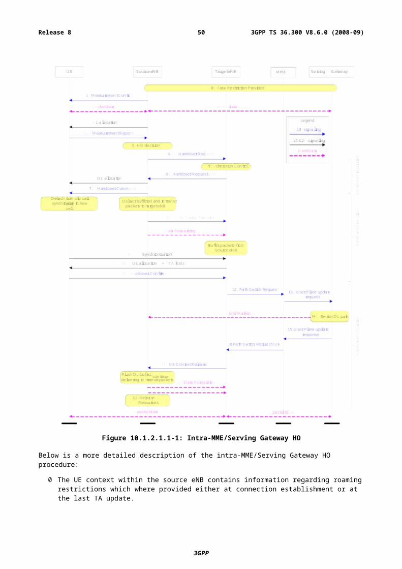
- Common procedure for FDD and TDD;
- One procedure irrespective of cell size;
The random access procedure is performed for the following five events:
- Initial access from RRC_IDLE;
- RRC Connection Re-establishment procedure;
- Handover;
- DL data arrival during RRC_CONNECTED requiring random access procedure;
- E.g. when UL synchronisation status is “non-synchronised”;
- UL data arrival during RRC_CONNECTED requiring random access procedure;
- E.g. when UL synchronisation status is "non-synchronised" or there are no PUCCH resources for SR available.
Furthermore, the random access procedure takes two distinct forms:
- Contention based (applicable to all five events);
- Non-contention based (applicable to only handover and DL data arrival).
Normal DL/UL transmission can take place after the random access procedure.
10.1.5.1 Contention based random access procedure
The contention based random access procedure is outlined on Figure 10.1.5.1-1 below:
Figure 10.1.5.1-1: Contention based Random Access Procedure
The four steps of the contention based random access procedures are:
1) Random Access Preamble on RACH in uplink:
- 6 bits to carry: a 5 bit random ID, and 1 bit to indicate information on size of message 3 or requested resource blocks (FFS) limited by radio conditions. The groups of signatures that are used for indicating the 1 bit information, as well as necessary thresholds are broadcast on system information.
NOTE: the total number of bits is 5 for TDD Frame Structure Type II.
2) Random Access Response generated by MAC on DL-SCH:
3GPP
3GPP TS 36.300 V8.6.0 (2008-09)50Release 8
- Semi-synchronous (within a flexible window of which the size is one or more TTI) with message 1;
- No HARQ;
- Addressed to RA-RNTI on PDCCH;
- Conveys at least RA-preamble identifier, Timing Alignment information, initial UL grant and assignment of Temporary C-RNTI (which may or may not be made permanent upon RRC Contention Resolution);
- Intended for a variable number of UEs in one DL-SCH message.
3) First scheduled UL transmission on UL-SCH:
- Uses HARQ;
- Size of the transport blocks depends on the UL grant conveyed in step 2 and is at least 80 bits.
- For initial access:
- Conveys the RRC Connection Request generated by the RRC layer and transmitted via CCCH;
- Conveys at least NAS UE identifier but no NAS message;
- RLC TM: no segmentation;
- For RRC Connection Re-establishment procedure:
- Conveys the RRC Connection Re-establishment Request generated by the RRC layer and transmitted via CCCH;
- RLC TM: no segmentation;
- Does not contain any NAS message.
- After handover, in the target cell:
- Conveys the ciphered and integrity protected RRC Handover Confirm generated by the RRC layer and transmitted via DCCH;
- Conveys the C-RNTI of the UE (which was allocated via the Handover Command);
- Includes an uplink Buffer Status Report when possible.
- For other events:
- Conveys at least the C-RNTI of the UE.
4) Contention Resolution on DL-SCH:
- Early contention resolution shall be used i.e. eNB does not wait for NAS reply before resolving contention
- Not synchronised with message 3;
- HARQ is supported;
- Addressed to:
- The Temporary C-RNTI on PDCCH for initial access and after radio link failure;
- The C-RNTI on PDCCH for UE in RRC_CONNECTED;
- HARQ feedback is transmitted only by the UE which detects its own UE identity, as provided in message 3, echoed in the RRC Contention Resolution message;
- For initial access and RRC Connection Re-establishment procedure, no segmentation is used (RLC-TM).
The Temporary C-RNTI is promoted to C-RNTI for a UE which detects RA success and does not already have a C-RNTI; it is dropped by others. A UE which detects RA success and already has a C-RNTI, resumes using its C-RNTI.
3GPP
3GPP TS 36.300 V8.6.0 (2008-09)51Release 8
10.1.5.2 Non-contention based random access procedure
The non-contention based random access procedure is outlined on Figure 10.1.5.2-1 below:
Figure 10.1.5.2-1: Non-contention based Random Access Procedure
The three steps of the non-contention based random access procedures are:
0) Random Access Preamble assignment via dedicated signalling in DL:
- eNB assigns to UE a non-contention Random Access Preamble (a Random Access Preamble not within the set broadcasted on BCH).
- Signalled via:
- HO command generated by target eNB and sent via source eNB for handover;
- PDCCH in case of DL data arrival.
1) Random Access Preamble on RACH in uplink:
- UE transmits the assigned non-contention Random Access Preamble.
2) Random Access Response on DL-SCH:
- Semi-synchronous (within a flexible window of which the size is one or more TTI) with message 1;
- No HARQ;
- Addressed to RA-RNTI on PDCCH;
- Conveys at least:
- Timing Alignment information and initial UL grant for handover;
- Timing Alignment information for DL data arrival;
- RA-preamble identifier.
- Intended for one or multiple UEs in one DL-SCH message.
10.1.5.3 Interaction model between L1 and L2/3 for Random Access Procedure
Random access procedure described above is modelled in Figure 10.1.5.3-1 below from L1 and L2/3 interaction point of view. L2/L3 receives indication from L1 whether ACK is received or DTX is detected after indication of Random Access Preamble transmission to L1. L2/3 indicates L1 to transmit first scheduled UL transmission (RRC Connection Request in case of initial access) if necessary or Random Access Preamble based on the indication from L1.
3GPP
3GPP TS 36.300 V8.6.0 (2008-09)52Release 8
Figure 10.1.5.3-1: Interaction model between L1 and L2/3 for Random Access Procedure
10.1.6 Radio Link FailureTwo phases governs the behaviour associated to radio link failure as shown on Figure 10.1.6-1:
- First phase:
- started upon radio problem detection;
- leads to radio link failure detection;
- no UE-based mobility;
- based on timer or other (e.g. counting) criteria (T1).
- Second Phase:
- started upon radio link failure detection or handover failure;
- leads to RRC_IDLE;
- UE-based mobility;
- Timer based (T2).
Figure 10.1.6-1: Radio Link Failure
Table 10.1.6-1 below describes how mobility is handled with respect to radio link failure:
3GPP
3GPP TS 36.300 V8.6.0 (2008-09)53Release 8
Table 10.1.6-1: Mobility and Radio Link Failure
Cases First Phase Second Phase T2 expiredUE returns to the same cell Continue as if no radio
problems occurredActivity is resumed by means of explicit signalling between UE and eNB
Go via RRC_IDLE
UE selects a different cell from the same eNB
N/A Activity is resumed by means of explicit signalling between UE and eNB
Go via RRC_IDLE
UE selects a cell of a prepared eNB (NOTE)
N/A Activity is resumed by means of explicit signalling between UE and eNB
Go via RRC_IDLE
UE selects a cell of a different eNB that is not prepared (NOTE)
N/A Go via RRC_IDLE Go via RRC_IDLE
NOTE: a prepared eNB is an eNB which has admitted the UE during an earlier executed HO preparation phase.
In the Second Phase, in order to resume activity and avoid going via RRC_IDLE when the UE returns to the same cell or when the UE selects a different cell from the same eNB, or when the UE selects a cell from a different eNB, the following procedure applies:
- The UE stays in RRC_CONNECTED;
- The UE accesses the cell through the random access procedure;
- The UE identifier used in the random access procedure for contention resolution (i.e. C-RNTI of the UE in the cell where the RLF occurred + physical layer identity of that cell + MAC based on the keys of that cell) is used by the selected eNB to authenticate the UE and check whether it has a context stored for that UE:
- If the eNB finds a context that matches the identity of the UE, it indicates to the UE that its connection can be resumed;
- If the context is not found, RRC connection is released and UE initiates procedure to establish new RRC connection. In this case UE is required to go via RRC_IDLE.
10.1.7 Radio Access Network SharingE-UTRAN shall support radio access network sharing based on support for multi-to-multi relationship between E-UTRAN nodes and EPC nodes (S1-flex).
If the E-UTRAN is shared by multiple operators, the system information broadcasted in each shared cell contains the PLMN-id of each operator (up to 6) and a single tracking area code (TAC) valid within all the PLMNs sharing the radio access network resources.
The UE shall be able to read up to 6 PLMN-ids, to select one of the PLMN-ids at initial attachment and to indicate this PLMN-id to the E-UTRAN in subsequent instances of the Random Access procedures (e.g. as defined in subclause 10.1.5). The E-UTRAN shall select an appropriate MME for the PLMN indicated by the UE. Once attached to an MME, the UE shall be able to indicate the allocated MME in subsequent instances of the Random Access procedures. Whether the indication of the selected PLMN or the allocated MME is contained in the temporary UE identity or signalled separately is FFS.
Handling of area restrictions for UE in ECM-CONNECTED shall follow the principles specified in sub-clause 10.4.
10.1.8 Handling of Roaming and Area Restrictions for UEs in ECM-CONNECTEDHandling of roaming/area restrictions and handling of subscription specific preferences in ECM-CONNECTED is performed in the eNB based on information provided by the EPC over the S1 interface.
3GPP
3GPP TS 36.300 V8.6.0 (2008-09)54Release 8
10.2 Inter RATService-based redirection between GERAN / UTRAN and E-UTRAN is supported in both directions. This should not require inter-RAT reporting in RRC CONNECTION REQUEST.
10.2.1 Cell reselectionA UE in RRC_IDLE performs cell reselection. The principles of this procedure are as follows:
- The UE makes measurements of attributes of the serving and neighbour cells to enable the reselection process:
- For a UE to search and measure neighbouring GERAN cells, the ARFCNs of the BCCH carriers need to be indicated in the serving cell system information (i.e., an NCL). The NCL does not contain BSICs or cell specific offsets and Qrxlevmin is given per frequency band.
- For a UE to search and measure neighbouring UTRAN cells, the serving cell can indicate an NCL containing a list of carrier frequencies and scrambling codes.
- Measurements may be omitted if the serving cell attribute fulfils particular search or measurement criteria.
- Cell reselection identifies the cell that the UE should camp on. It is based on cell reselection criteria which involves measurements of the serving and neighbour cells:
- Inter-RAT reselection is based on absolute priorities where UE tries to camp on highest priority RAT available. Absolute priorities for inter-RAT reselection are provided only by the RPLMN and valid only within the RPLMN; priorities are given by the system information and valid for all UEs in a cell, specific priorities per UE can be signalled in the RRC Connection Release message. A validity time can be associated with UE specific priorities.
- It should be possible to prevent the UE from reselecting to specific detected neighbouring cells;
- The UE is allowed to "leave" the source E-UTRAN cell to read the target GERAN cell broadcast, in order to determine its "suitability", prior to completing the cell reselection;
- Cell reselection can be speed dependent (speed detection based on UTRAN solution);
Cell access restrictions apply as for UTRAN, which consist of access class (AC) barring and cell reservation (e.g. for cells "reserved for operator use") applicable for mobiles in RRC_IDLE mode.
When performing cell reselection while the UE is camped on another RAT, the principles of this procedure are as follows:
- The UE measures attributes of the E-UTRA neighbouring cells:
- Only the carrier frequencies need to be indicated to enable the UE to search and measure E-UTRA neighbouring cells;
- Cell reselection identifies the cell that the UE should camp on. It is based on cell reselection criteria which involves measurements of the serving and neighbour cells:
- For E-UTRA neighbouring cells, there is no need to indicate cell-specific cell reselection parameters i.e. these parameters are common to all neighbouring cells on an E-UTRA frequency;
- Cell reselection parameters are applicable to all UEs in a cell, but it is possible to configure specific reselection parameters per UE group or per UE.
- It should be possible to prevent the UE from reselecting to specific detected neighbouring cells.
10.2.2 HandoverInter RAT HO is designed so that changes to GERAN and UTRAN are minimised. This can be done by following the principles specified for GERAN to/from UTRAN intersystem HO. In particular the following principles are applied to E-UTRAN Inter RAT HO design:
3GPP
3GPP TS 36.300 V8.6.0 (2008-09)55Release 8
1. Inter RAT HO is network controlled through source access system. The source access system decides about starting the preparation and provides the necessary information to the target system in the format required by the target system. That is, the source system adapts to the target system. The actual handover execution is decided in the source system.
2. Inter RAT HO is backwards handover, i.e. radio resources are prepared in the target 3GPP access system before the UE is commanded by the source 3GPP access system to change to the target 3GPP access system.
3. To enable backwards handover, and while RAN level interfaces are not available, a control interface exists in CN level. In Inter RAT HO involving E-UTRAN access, this interface is between 2G/3G SGSN and corresponding MME/Serving Gateway.
4. The target access system will be responsible for giving exact guidance for the UE on how to make the radio access there (this includes radio resource configuration, target cell system information etc.). This information is given during the handover preparation and should be transported completely transparently through the source access system to the UE.
5. Mechanisms for avoiding or mitigating the loss of user data (i.e. forwarding) can be used until the 3GPP Anchor determines that it can send DL U-plane data directly to the target system.
6. The handover procedure should not require any UE to CN signalling in order for data to start to flow in the target system. This requires that the security context, UE capability context and QoS context is transferred (or translated) within the network between source and target system.
7. Similar handover procedure should apply for handovers of both real time and non-real time services.
8. Similar handover procedure should apply for both Inter RAT Handover and intra-LTE Handover with EPC node change.
9. Network controlled mobility is supported even if no prior UE measurements have been performed on the target cell and/or frequency i.e. “blind HO” is supported.
10.2.2a Inter-RAT cell change order to GERAN with NACCFor interworking towards GERAN, inter-RAT cell change order with NACC is supported even if no prior UE measurements have been performed on the system i.e. “blind NACC” is supported.
10.2.2b Inter-RAT handovers from E-UTRAN
10.2.2b.1 Data forwarding
10.2.2b.1.1 For RLC-AM bearers
Upon handover, the eNB may forward all downlink PDCP SDUs that have not been acknowledged by the UE to the target node. In addition, the eNB may forward fresh data arriving over S1 to the target node.
NOTE: Any assigned PDCP SNs are not forwarded because of PDCP reset.
NOTE: Target node does not have to wait for the completion of forwarding from the eNB before it begins transmitting packets to the UE.
The eNB discards any remaining downlink RLC PDUs.
NOTE: eNB does not need to abort ongoing RLC transmissions with the UE as it starts data forwarding to the target node.
Upon handover, the eNB may forward uplink PDCP SDUs successfully received to the Serving Gateway and shall discard any remaining uplink RLC PDUs.
Correspondingly, the eNB does not forward the downlink and uplink RLC context.
In-sequence delivery of upper layer PDUs during handover is not guaranteed.
3GPP
3GPP TS 36.300 V8.6.0 (2008-09)56Release 8
10.2.2b.1.2 For RLC-UM bearers
Upon handover, the eNB does not forward to the target node downlink PDCP SDUs for which transmission had been completed in the source cell. PDCP SDUs that have not been transmitted may be forwarded. In addition, the eNB may forward fresh data arriving over S1 to the target node. The eNB discards any remaining downlink RLC PDUs.
Upon handover, the eNB may forward all uplink PDCP SDUs successfully received to the Serving Gateway and discards any remaining uplink RLC PDUs.
Correspondingly, the eNB does not forward the downlink and uplink RLC context.
10.2.3 Measurements
10.2.3.1 Inter-RAT handovers from E-UTRAN
Measurements to be performed by a UE for inter-RAT mobility can be controlled by E-UTRAN, using broadcast or dedicated control. In RRC_CONNECTED state, a UE shall follow the measurement parameters specified by RRC directed from the E-UTRAN (e.g. as in UTRAN MEASUREMENT_CONTROL).
UE performs inter-RAT neighbour cell measurements during DL/UL idle periods that are provided by the network through suitable DRX/DTX period or packet scheduling if necessary.
10.2.3.2 Inter-RAT handovers to E-UTRAN
From UTRAN, UE performs E-UTRAN measurements by using idle periods created by compressed mode (CELL_DCH), FACH measurement occasions (CELL_FACH - FFS), or DRX (other states).
From GERAN, E-UTRAN measurements are performed in the same way as WCDMA measurements for handover to UTRAN: E-UTRAN measurements are performed in GSM idle frames in a time multiplexed manner. However, it should be discussed with GERAN how to ensure that inter-RAT measurements do not take too much measurement time, while the requested 3GPP inter-RAT measurements can be performed well enough.
Design constraints of 3GPP inter-RAT measurements should be considered when L1 details of E-UTRAN concept are defined.
10.2.3.3 Inter-RAT cell reselection from E-UTRAN
In RRC_IDLE state, a UE shall follow the measurement parameters specified by the E-UTRAN broadcast (as in UTRAN SIB). The use of dedicated measurement control is possible through the provision of UE specific priorities (see sub-clause 10.2.4).
10.2.3.4 Limiting measurement load at UE
Introduction of E-UTRA implies co-existence of various UE capabilities. Each UE may support different combinations of RATs, e.g., E-UTRA, UTRA, GSM, and non-3GPP RATs, and different combinations of frequency bands, e.g., 800 MHz, 1.7 GHz, 2 GHZ, etc. Despite such heterogeneous environment, the measurement load at UE should be minimised. To limit the measurement load and the associated control load:
- E-UTRAN can configure the RATs to be measured by UE;
- The number of measurement criteria (event and periodic reporting criteria) should be limited (as in TS 25.133 subclause 8.3.2 [7]);
- E-UTRAN should be aware of the UE capabilities for efficient measurement control, to prevent unnecessary waking up of the measurement entity;
- Blind HO (i.e., HO without measurement reports from UE) is possible.
3GPP
3GPP TS 36.300 V8.6.0 (2008-09)57Release 8
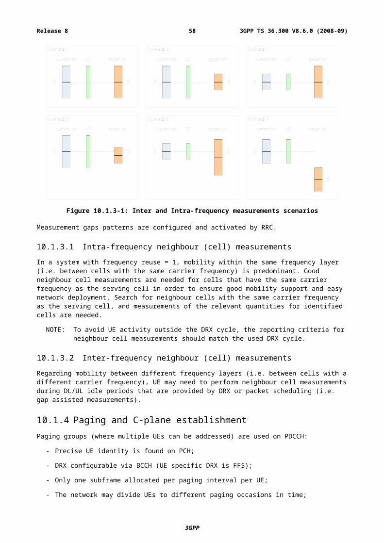
10.2.4 Network AspectsInter-frequency/inter-RAT UE based mobility relies on a “priority based scheme”, where the network configures a list of RATs/frequencies to be taken as basis for UE’s inter-frequency/inter-RAT cell reselection decisions in priority order. E-UTRAN cells can enable inter-frequency/inter-RAT cell reselection by broadcasting a common priority valid for all UEs in a given cell in addition to other inter-frequency/inter-RAT information.
NOTE: The same principles apply in UTRAN.
These common priorities can be overwritten by E-UTRAN through dedicated signalling to individual UEs at RRC_CONNECTED to RRC_IDLE transition.
NOTE: In order to have consistent inter-RAT operation, the same principles apply to inter-RAT reselection to E-UTRAN. For UTRAN this includes also the transitions within RRC_CONNECTED state from CELL_DCH to CELL_PCH and URA_PCH.
Setting dedicated priorities by E-UTRAN can be based on subscription related information provided by the MME.
NOTE: The same principle have been taken as a working assumption in UTRAN (awaiting for SA2 decision on feasibility of providing subscription related information by the CN).
10.3 Mobility between E-UTRAN and Non-3GPP radio technologies
10.3.1 UE Capability ConfigurationA UE shall be able to communicate with the E-UTRAN about its radio access capability, such as the system (including the release and frequency band) it supports and it’s receive and transmit capabilities (single/dual radio, dual receiver). UE shall transfer its capability about other radio technologies over E-UTRAN using the same procedure used to carry its E-UTRAN radio capability.
10.3.2 Mobility between E-UTRAN and cdma2000 networkThis section describes the E-UTRAN mechanisms to support idle and active mode mobility between E-UTRAN and cdma2000 HRPD or 1xRTT. The overall system is described in [17].
10.3.2.1 Tunnelling of cdma2000 Messages over E-UTRAN between UE and cdma2000 Access Nodes
In order to efficiently support handover procedures when on E-UTRAN with a cdma2000 target system, cdma2000 messages are sent transparently to the target system over the E-UTRAN, with the eNB and MME acting as relay points.
To support the MME in its selection of the correct target system node to which it should route an Uplink tunnelled message and to provide the target system with information that is needed to resolve technology-specific measurement information (RouteUpdate and pilot strength measurements) that are delivered to the cdma2000 system each eNB cell is associated with a cdma2000 HRPD SectorID and/or with a cdma2000 1xRTT SectorID (generically referred to as cdma2000 reference cellid). This cdma2000 reference cellid is provided by the eNB to the MME using the cdma2000 message transfer capability over S1-AP and forwarded to the target system via the S101 interface and corresponding interface to the cdma2000 1xRTT system.
Tunnelling is achieved over the E-UTRAN radio interface by encapsulating tunnelled cdma2000 messages in the UL Information Transfer (for pre-registration signalling) or UL Handover Preparation transfer (for handover signalling) and DL Information Transfer RRC messages (e.g., similar to UMTS Uplink/Downlink Direct Transfer). The reason for using different UL transfer messages is so that the UL Handover Preparation transfer messages can use a higher priority signalling radio bearer. For the UL/DL Information Transfer messages a specific IE in these RRC messages is used to identify the type of information contained in the message (e.g., NAS, TunneledMsg). Additionally if the message is carrying a tunnelled message, an additional IE is included to carry cdma2000 specific RRC Tunnelling Procedure Information (e.g. RAT type).
3GPP
3GPP TS 36.300 V8.6.0 (2008-09)58Release 8
AS level security will be applied for these UL Information Transfer / UL Handover Preparation Transfer and DL Information Transfer RRC messages as normal but there is no NAS level security for these tunnelled cdma2000 messages.
Figure 10.3.2.1-1: Downlink Direct Transfer
Figure 10.3.2.1-2: Uplink Direct Transfer
Tunnelling to the MME is achieved over the S1-MME interface by encapsulating the tunnelled cdma2000 message in a new S1 CDMA tunneling messages. These S1 messages carry in addition to the tunneled message some additional cdma2000 specific IEs (e.g. cdma2000 Reference Cell Id, RAT type, cdma2000 message type).
10.3.2.2 Mobility between E-UTRAN and HRPD
10.3.2.2.1 Mobility from E-UTRAN to HRPD
10.3.2.2.1.1 HRPD System Information Transmission in E-UTRAN
The HRPD system information block (SIB) shall be sent on the E-UTRAN BCCH. The UE shall monitor the E-UTRAN BCCH during the RRC_IDLE and RRC_CONNECTED modes to retrieve the HRPD system information for the preparation of cell reselection or handover from the E-UTRAN to HRPD system. HRPD system information may also be provided to the UE by means of dedicated signalling. The HRPD system information contains HRPD neighbouring cell information, cdma timing information, as well as information controlling the HRPD pre-registration.
10.3.2.2.1.2 Measuring HRPD from E-UTRAN
Measurement events and parameters for HRPD measurements are to be aligned with those defined in section 10.2.3.
10.3.2.2.1.2.1 Idle Mode Measurement Control
UE shall be able to make measurements on the HRPD cells in RRC_IDLE mode to perform cell re-selection.
3GPP
3GPP TS 36.300 V8.6.0 (2008-09)59Release 8
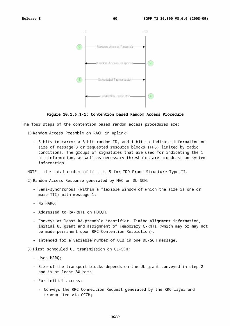
The intra-3GPP inter-RAT idle mode measurement control is re-used to control the idle mode measurements on HRPD. The UE performs measurement on HRPD when the signal quality from E-UTRAN serving cell falls below a given threshold.
10.3.2.2.1.2.2 Active Mode Measurement Control
In RRC_CONNECTED mode, the UE shall perform radio measurements on the HRPD network when directed by the E-UTRAN network. The network provides the required HRPD neighbour cell list information and measurement controls to the UE through dedicated RRC signalling. When needed the eNB is responsible for configuring and activating the HRPD measurements on the UE via the dedicated RRC signalling message. Periodic and event-triggered measurements are supported.
For single-radio terminals, measurement gaps are needed to allow the UE to switch into the HRPD network and do radio measurements. These measurement gaps are network-controlled. The eNB is responsible for configuring the gap pattern and providing it to the UE through RRC dedicated signalling. Terminals with a dual receiver perform measurements on HRPD neighbour cells without tuning away from the E-UTRAN network. No DL gap patterns will be required for UEs which are capable of simultaneous reception on the involved frequency bands. No UL gap patterns will be required for UEs which are capable simultaneous transmission in one access and measuring on another access.
10.3.2.2.1.2.3 Active Mode Measurement
In RRC_CONNECTED mode, the UE measures the strengths of each of the HRPD neighbour cells and reports them in an RRC message.
10.3.2.2.1.3 Pre-registration to HRPD Procedure
Pre-registration allows a UE to establish a presence with an HRPD system in advance of a cell re-selection or handover. E-UTRAN network instructs the UE whether the pre-registration is needed over broadcast channel and in a dedicated RRC message.
The signalling procedure is transparent to E-UTRAN network. In the pre-registration to HRPD, messages shall be tunnelled inside RRC and S1-AP messages between the UE and MME and in a generic "transfer" message between source MME and target accesss network.
The UE is responsible for maintaining the HRPD context e.g. by performing periodic re-registrations if needed. The UE will use pre-registration zone information (including the current HRPD Pre-registration Zone and a list of HRPD Secondary Pre-registration Zone ID) to decide whether a re-registration shall be performed. A dual-receiver UE can ignore the parameter. E-UTRAN will provide the pre-registration zone information on the E-UTRAN system information broadcast channel or dedicated RRC signalling (unless it is determined that the UE will read the E-UTRAN system information broadcast channel in RRC_CONNECTED). Re-registrations are only allowed in areas where pre-registration is requested.
The managing of pre-registration and re-registration is handled by HRPD upper layer. The UE should indicate if it is pre-registered when sending measurement reports on cdma2000 cells.
10.3.2.2.1.4 E-UTRAN to HRPD Cell Re-selection
The pre-condition for cell re-selection from E-UTRAN to HRPD is that the UE has previously established a presence in the target HRPD network, either through the pre-registration procedure or previous HRPD attachment. The UE performs Cell re-selection to HRPD while in RRC_IDLE.
Cell reselection from E-UTRAN to HRPD should be aligned with 3GPP inter RAT cell reselection mechanism. . .
10.3.2.2.1.5 E-UTRAN to HRPD Handover
The pre-condition for the E-UTRAN to HRPD Handover procedure is that the UE is attached in the E-UTRAN network in E-UTRAN_ACTIVE state and has pre-registered with the HRPD network. Based on measurement reports received from the UE the eNB initiates a handover by sending an RRC HANDOVER FROM E-UTRA PREPARATION REQUEST message to the UE to indicate to the UE that it should begin the handover procedure. This message shall include the specified target RAT type and any cdma2000 specific HRPD parameters needed by the UE to create the appropriate HRPD messages needed to request a connection. Upon reception of this message the UE should begin handover signalling towards the HRPD access. The HRPD handover signalling is tunnelled through E-UTRAN between the UE and HRPD network. These HRPD parameters and HRPD messages are transparent to E-UTRAN. The set of the required HRPD parameters are out of scope of this specification.
3GPP
3GPP TS 36.300 V8.6.0 (2008-09)60Release 8
The messages are transferred inside RRC transfer messages and S1 CDMA2000 tunneling messages. The MME will, based on indication provided by the HRPD network, get information about if the handover succeeded or failed making it possible for the MME set the handover status in the S1 CDMA2000 tunneling messages (e.g. handover success, handover failure). In case the handover succeeded E-UTRAN will include the tunnelled “CDMA2000 handover command”, which will be sent to the UE, inside the RRC MOBILITY FROM E-UTRA message.
The UE can continue to send and receive data on the E-UTRAN radio until it receives the RRC MOBILITY FROM E-UTRA message including a tunnelled “CDMA2000 handover command”. After this message is received by the UE, the UE shall leave the E-UTRAN radio and start acquiring the HRPD traffic channel. The HRPD handover signalling is tunnelled between the UE and HRPD network.
10.3.2.2.2 Mobility from HRPD to E-UTRAN
Mobility from HRPD to E-UTRAN has no impact on the E-UTRAN.
10.3.2.3 Mobility between E-UTRAN and cdma2000 1xRTT
10.3.2.3.1 Mobility from E-UTRAN to cdma2000 1xRTT
10.3.2.3.1.1 cdma2000 1xRTT System Information Transmission in E-UTRAN
The cdma2000 1xRTT system information block (SIB) shall be sent on E-UTRAN BCCH. The UE shall monitor the E-UTRAN BCCH during the LTE_IDLE and RRC_CONNECTED modes to retrieve the 1xRTT system information for the preparation of handover from the E-UTRAN to cdma 2000 1xRTT system. 1xRTT system information may also be provided to the UE by means of dedicated signalling. The 1xRTT system information contains 1xRTT neighbouring cell information and cdma timing information.
10.3.2.3.1.2 Measuring cdma2000 1xRTT from E-UTRAN
Measurement events and parameters for 1xRTT measurements are to be aligned with those defined in section 10.2.3.
10.3.2.3.1.2.1 Idle Mode Measurement Control
UE shall be able to make measurements on the 1xRTT system cells in LTE_IDLE mode to perform cell re-selection. UE shall perform cdma2000 1xRTT neighbour cell measurements during DRX periods, between paging occasions.
The intra-3GPP inter-RAT idle mode measurement control is re-used to control the idle mode measurements on cdma2000 1xRTT. The UE performs measurement on cdma2000 1xRTT when the signal quality from E-UTRAN serving cell falls below a given threshold.
10.3.2.3.1.2.2 Active Mode Measurement Control
In the E-UTRAN network, in RRC_CONNECTED mode, the UE shall perform radio measurements on the cdma2000 1xRTT network when directed by the E-UTRAN network. The network provides the required cdma2000 1xRTT neighbour cell list information and measurement controls to the UE through dedicated RRC signalling. When needed the eNB is responsible for configuring and activating the cdma2000 1xRTT measurements on the UE via the dedicated RRC signalling message. As for intra-3GPP inter-RAT measurement reporting, periodic and event-triggered measurements are supported.
For single-radio terminals, measurement gaps are needed to allow the UE to switch into the cdma2000 1xRTT network and do radio measurements. These Measurement gaps are network-controlled. The eNB is responsible for configuring the gap pattern and providing it to the UE through RRC dedicated signalling. Terminals with a dual receiver perform measurements on cdma2000 1xRTT neighbour cells without tuning away from the E-UTRAN network. No DL gap patterns will be required for UEs which are capable of simultaneous reception on the involved frequency bands. No UL gap patterns will be required for UEs which are capable simultaneous transmission in one access and measuring on another access.
10.3.2.3.1.2.3 Active Mode Measurement
In RRC_CONNECTED mode, the UE measures the strengths of each of the cdma2000 1xRTT neighbour cells and reports them in an RRC Message.
3GPP
3GPP TS 36.300 V8.6.0 (2008-09)61Release 8
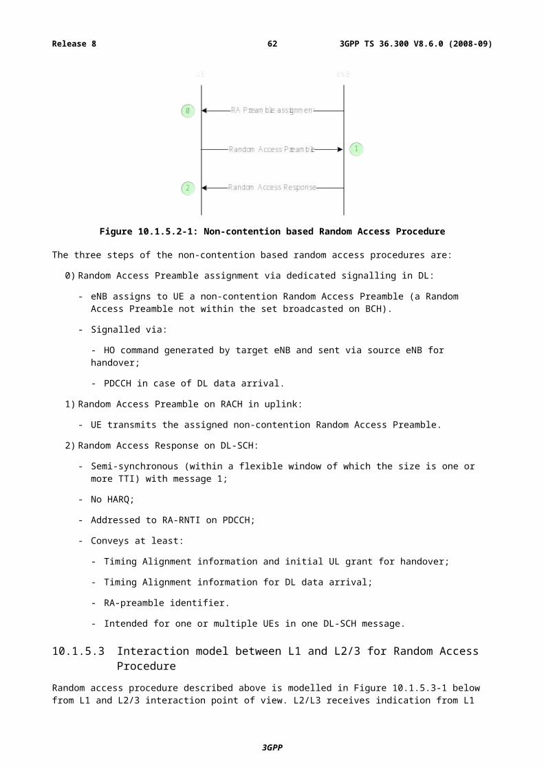
10.3.2.3.1.3 E-UTRAN to cdma2000 1xRTT Cell Re-selection
UE performs Cell re-selection to cdma2000 1xRTT while in RRC_IDLE.
Cell reselection from E-UTRAN to 1xRTT should be aligned with 3GPP inter RAT cell reselection mechanism.
10.3.2.3.1.4 E-UTRAN to cdma2000 1xRTT Handover
In the high level procedure for handover from E-UTRAN to cdma2000 1xRTT, registration and handover is performed directly after the handover decision has been made. Based on measurement reports received from the UE the eNB initiates a handover by sending a RRC HANDOVER FROM E-UTRA PREPARATION REQUEST message to the UE to indicate to the UE that it should begin the handover procedure. This message shall include the specified target RAT type and any cdma2000 specific 1xRTT access parameters needed by the UE to create the appropriate 1xRTT Origination Request message. The 1xRTT handover signalling is tunnelled between the UE and 1xRTT network. The 1xRTT access parameters and 1xRTT messages are transparent to E-UTRAN. The set of the required 1xRTT access parameters are out of scope of this specification.
The messages are transferred inside RRC transfer messages and S1 CDMA2000 tunneling messages. The MME will, based on indication provided by the 1xRTT network, get information about if the handover succeeded or failed making it possible for the MME set the handover status in the S1 CDMA2000 tunneling messages (e.g. handover success, handover failure). In case the handover succeeded E-UTRAN will include the tunnelled “CDMA2000 handover command”, which will be sent to the UE, inside the RRC MOBILITY FROM E-UTRA message.
The UE can continue to send and receive data on the E-UTRAN radio until it receives the RRC MOBILITY FROM E-UTRA message including a tunnelled “CDMA2000 handover command”. After this message is received by the UE, the UE shall leave the E-UTRAN radio and start acquiring the 1xRTT traffic channel.
10.3.2.3.2 Mobility from cdma2000 1xRTT to E-UTRAN
Mobility from cdma2000 1xRTT has no impact on E-UTRAN.
10.4 Area RestrictionsInformation on which area restrictions to be applied during ECM-CONNECTED state is provided by the MME at context setup over the S1 interface.
The eNB shall store the UE restriction information and use it to determine whether the UE has access to radio resources in the E-UTRAN. The source eNB should apply restriction handling when selecting a target eNB.
The available UE restriction information shall be propagated by the source eNB over X2 at intra E-UTRAN handover.
10.5 Mobility to and from CSG cells
10.5.0 Principles for idle-mode mobility with CSG cells
10.5.0.1 Intra-frequency mobility
Intra-frequency mobility in idle mode in the presence of “allowed” CSG cells (i.e., CSG cells that the UE is allowed to camp on) is based on cell ranking and reselection using the “best cell principle”: The UE ranks the candidate cells and reselects to the highest-ranked one.
10.5.0.2 Inter-frequency mobility
[FFS]
3GPP
3GPP TS 36.300 V8.6.0 (2008-09)62Release 8
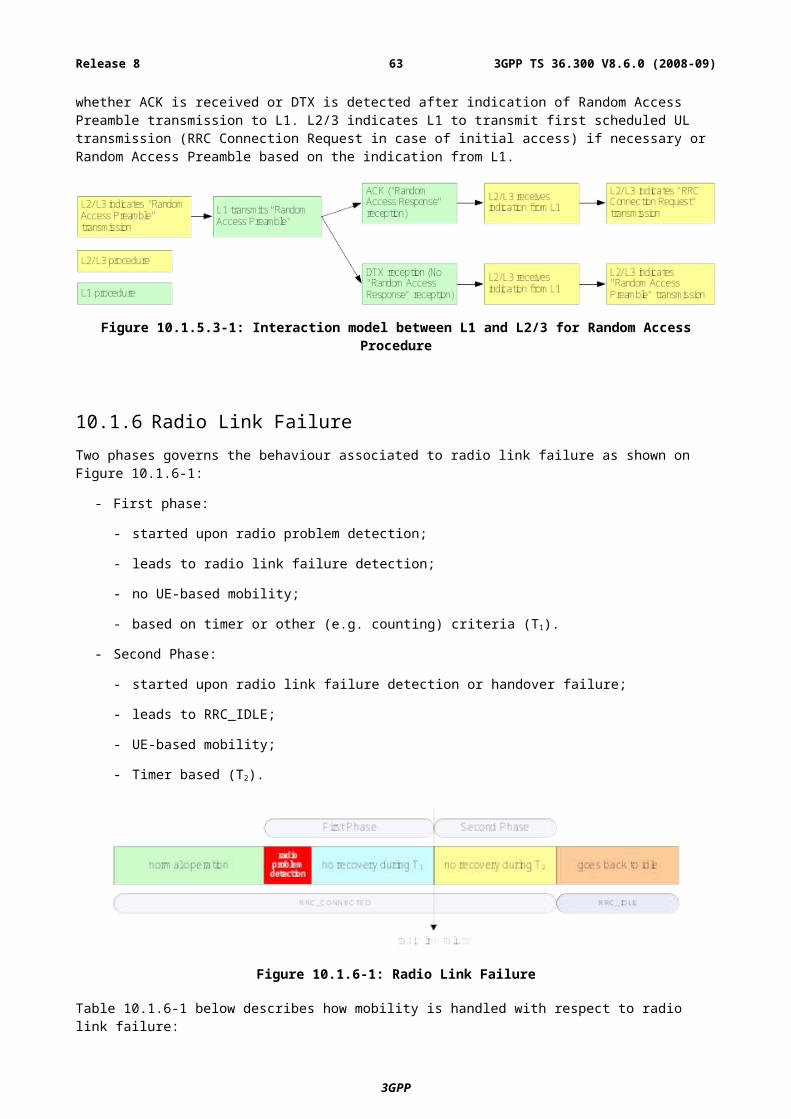
10.5.1 Inbound mobility to CSG cells
10.5.1.1 RRC_IDLE
Cell selection/reselection to CSG cells is based on a UE autonomous search function. The search function determines itself when/where to search.
It is FFS whether specific UE procedures or performance requirements will be specified.
UE checks the suitability of CSG cells (identified by the 1 bit indicator) based on the CSG whitelist in the UE (provided by upper layers). A CSG cell is only suitable for a UE if it belongs to its whitelist.
The automated searching for the CSG cells by the UE shall be disabled by the search function, if the CSG whitelist configured in the UE is empty.
In addition, manual selection of CSG cells is supported.
Cell selection/reselection to CSG cells does not require the network to provide neighbour cell information to the UE. The neighbour cell information can be provided to help the UE in specific cases, e.g. where the network wishes to trigger the UE to search for CSG cells.
It is FFS whether a CSG-specific offset is provided to the UE to modify the ranking of allowed CSG cells against other cells.
10.5.1.2 RRC_CONNECTED
UE autonomously searches for CSG cells and can indicate the need for measurement gaps to the network (e.g. to check the suitability of the CSG cell). Upon network decision measurement gaps might be granted.
The automated searching for the CSG cells by the UE shall be disabled by the search function, if the CSG whitelist configured in the UE is empty.
UE checks the suitability of CSG cells (identified by the 1 bit indicator) based on the CSG whitelist in the UE (provided by upper layers). The UE shall report suitable CSG cells and/or any CSG cells including an indication that particular CSG cells are suitable to the serving cell.
Measurement reporting of CSG cells does not require the network to provide neighbour cell information to the UE. The neighbour cell information can be provided to help the UE in specific cases, e.g. where the network wishes to trigger the UE to search for CSG cells.
NOTE: in some case it might require that appropriate gaps are given to the UE.
10.5.2 Outbound mobility from CSG cells
10.5.2.1 RRC_IDLE
For a UE leaving a CSG cell in idle mode normal cell reselection based on configuration from the BCCH of the CSG cell applies. It is FFS whether this configuration is modified by the use of a CSG offset in the ranking.
10.5.2.2 RRC_CONNECTED
For a UE leaving a CSG cell in active mode normal network controlled mobility applies.
11 Scheduling and Rate ControlIn order to utilise the SCH resources efficiently, a scheduling function is used in MAC. In this subclause, an overview of the scheduler is given in terms of scheduler operation, signalling of scheduler decisions, and measurements to support scheduler operation.
3GPP
3GPP TS 36.300 V8.6.0 (2008-09)63Release 8
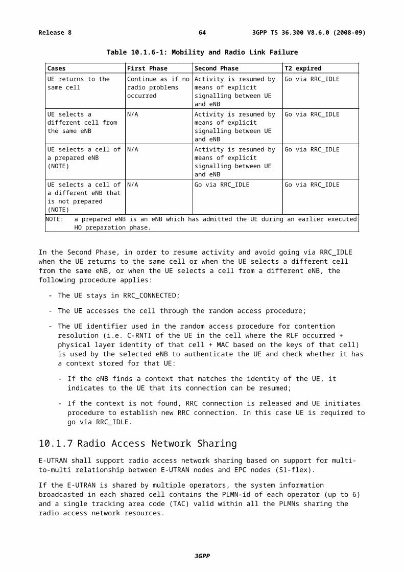
11.1 Basic Scheduler OperationMAC in eNB includes dynamic resource schedulers that allocate physical layer resources for the DL-SCH and UL-SCH transport channels. Different schedulers operate for the DL-SCH and UL-SCH.
The scheduler should take account of the traffic volume and the QoS requirements of each UE and associated radio bearers, when sharing resources between UEs. Only “per UE” grants are used to grant the right to transmit on the UL-SCH (i.e. there are no “per UE per RB” grants).
Schedulers may assign resources taking account the radio conditions at the UE identified through measurements made at the eNB and/or reported by the UE.
Radio resource allocations can be valid for one or multiple TTIs.
Resource assignment consists of physical resource blocks (PRB) and MCS. Allocations for time periods longer than one TTI might also require additional information (allocation time, allocation repetition factor…).
11.1.1 Downlink SchedulingIn the downlink, E-UTRAN can dynamically allocate resources (PRBs and MCS) to UEs at each TTI via the C-RNTI on PDCCH(s). A UE always monitors the PDCCH(s) in order to find possible allocation when its downlink reception is enabled (activity governed by DRX when configured).
In addition, E-UTRAN can allocate semi-persistent downlink resources for the first HARQ transmissions to UEs:
- RRC defines the periodicity of the semi-persistent downlink grant;
- PDCCH indicates whether the downlink grant is a semi-persistent one i.e. whether it can be implicitly reused in the following TTIs according to the periodicity defined by RRC.
When required, retransmissions are explicitly signalled via the PDCCH(s). In the sub-frames where the UE has semi-persistent downlink resource, if the UE cannot find its C-RNTI on the PDCCH(s), a downlink transmission according to the semi-persistent allocation that the UE has been assigned in the TTI is assumed. Otherwise, in the sub-frames where the UE has semi-persistent downlink resource, if the UE finds its C-RNTI on the PDCCH(s), the PDCCH allocation overrides the semi-persistent allocation for that TTI and the UE does not decode the semi-persistent resources.
11.1.2 Uplink SchedulingIn the uplink, E-UTRAN can dynamically allocate resources (PRBs and MCS) to UEs at each TTI via the C-RNTI on PDCCH(s). A UE always monitors the PDCCH(s) in order to find possible allocation for uplink transmission when its downlink reception is enabled (activity governed by DRX when configured).
In addition, E-UTRAN can allocate a semi-persistent uplink resource for the first HARQ transmissions and potentially retransmissions to UEs:
- RRC defines the periodicity of the semi-persistent uplink grant;
- PDCCH indicates whether the uplink grant is a semi-persistent one i.e. whether it can be implicitly reused in the following TTIs according to the periodicity defined by RRC.
In the sub-frames where the UE has semi-persistent uplink resource, if the UE cannot find its C-RNTI on the PDCCH(s), an uplink transmission according to the semi-persistent allocation that the UE has been assigned in the TTI can be made. The network performs decoding of the pre-defined PRBs according to the pre-defined MCS. Otherwise, in the sub-frames where the UE has semi-persistent uplink resource, if the UE finds its C-RNTI on the PDCCH(s), the PDCCH allocation overrides the persistent allocation for that TTI and the UE’s transmission follows the PDCCH allocation, not the semi-persistent allocation. Retransmissions are either implicitly allocated in which case the UE uses the semi-persistent uplink allocation, or explicitly allocated via PDCCH(s) in which case the UE does not follow the semi-persistent allocation.
NOTE: there is no blind decoding in uplink and when the UE does not have enough data to fill the allocated resource, padding is used.
3GPP
3GPP TS 36.300 V8.6.0 (2008-09)64Release 8
11.2 Void
11.3 Measurements to Support Scheduler OperationMeasurement reports are required to enable the scheduler to operate in both uplink and downlink. These include transport volume and measurements of a UEs radio environment.
Uplink buffer status reports (BSR) are needed to provide support for QoS-aware packet scheduling. In E-UTRAN uplink buffer status reports refer to the data that is buffered in for a group of radio bearer (RBG) in the UE. Four RBGs and two formats are used for reporting in uplink:
- A short format for which only one BSR (of one RBG) is reported;
- A long format for which all four BSRs (of all four RBGs) are reported.
Uplink buffer status reports are transmitted using MAC signalling.
11.4 Rate Control of GBR and AMBR
11.4.1 DownlinkThe eNB guarantees the downlink GBR associated with a GBR bearer and enforces the downlink AMBR associated with a group of Non-GBR bearers.
11.4.2 UplinkThe UE has an uplink rate control function which manages the sharing of uplink resources between radio bearers. RRC controls the uplink rate control function by giving each bearer a priority and a prioritised bit rate (PBR). The values signalled may not be related to the ones signalled via S1 to the eNB.
The uplink rate control function ensures that the UE serves its radio bearer(s) in the following sequence:
1. All the radio bearer(s) in decreasing priority order up to their PBR;
2. All the radio bearer(s) in decreasing priority order for the remaining resources assigned by the grant.
NOTE1: In case the PBRs are all set to zero, the first step is skipped and the radio bearer(s) are served in strict priority order: the UE maximises the transmission of higher priority data.
NOTE2: By limiting the total grant to the UE, the eNB can ensure that the AMBR is not exceeded.
If more than one radio bearer has the same priority, the UE shall serve these radio bearers equally.
11.5 CQI reporting for SchedulingThe time and frequency resources used by the UE to report CQI are under the control of the eNB. CQI reporting can be either periodic or aperiodic. A UE can be configured to have both periodic and aperiodic reporting at the same time. In case both periodic and aperiodic reporting occurs in the same subframe, only the aperiodic report is transmitted in that subframe.
For efficient support of localized, distributed and MIMO transmissions, E-UTRA supports three types of CQI reporting:
- Wideband type: providing channel quality information of entire system bandwidth of the cell;
- Multi-band type: providing channel quality information of some subset(s) of system bandwidth of the cell;
- MIMO type: FFS.
3GPP
3GPP TS 36.300 V8.6.0 (2008-09)65Release 8
Periodic CQI reporting is defined by the following characteristics:
- When the UE is allocated PUSCH resources in a subframe where a periodic CQI report is configured to be sent, the periodic CQI report is transmitted together with uplink data on the PUSCH. Otherwise, the periodic CQI reports are sent on the PUCCH.
Aperiodic CQI reporting is defined by the following characteristics:
- The report is scheduled by the eNB via the PDCCH;
- Transmitted together with uplink data on PUSCH.
When a CQI report is transmitted together with uplink data on PUSCH, it is multiplexed with the transport block by L1 (i.e. the CQI report is not part of the uplink the transport block).
The eNB configures a set of sizes and formats of the reports. Size and format of the report depends on whether it is transmitted over PUCCH or PUSCH and whether it is a periodic or aperiodic CQI report.
12 DRX in RRC_CONNECTED In order to enable reasonable UE battery consumption, DRX in E-UTRAN is characterised by the following:
- Per UE mechanism (as opposed to per radio bearer);
- No RRC or MAC substate to distinguish between different levels of DRX;
- Available DRX values are controlled by the network and start from non-DRX up to x seconds. Value x may be as long as the paging DRX used in ECM-IDLE;
- Measurement requirement and reporting criteria can differ according to the length of the DRX interval i.e. long DRX intervals may experience more relaxed requirements;
- Irrespective of DRX, UE may use first available RACH opportunity to send an UL measurement report;
- Immediately after sending a measurement report, the UE may change its DRX. This mechanism would be pre-configured by the eNB;
- HARQ operation related to data transmission is independent of DRX operation and the UE wakes up to read the PDCCH for possible retransmissions and/or ACK/NAK signalling regardless of DRX In the downlink, a timer is used to limit the time the UE stays awake awaiting for a retransmission;
- When DRX is configured, the UE may be further configured with an "on-duration" timer during which time the UE monitors the PDCCHs for possible allocations;
- When DRX is configured, periodic CQI reports can only be sent by the UE during the “active-time”. RRC can further restrict periodic CQI reports so that they are only sent during the on-duration;
- A timer in the UE is used to detect need for obtaining timing advance.
The following definitions apply to DRX in E-UTRAN:
- on-duration: duration in downlink subframes that the UE waits for, after waking up from DRX, to receive PDCCHs. If the UE successfully decodes a PDCCH, the UE stays awake and starts the inactivity timer;
- inactivity-timer: duration in downlink subframes that the UE waits to successfully decode a PDCCH, from the last successful decoding of a PDCCH, failing which it re-enters DRX. The UE shall restart the inactivity timer following a single successful decoding of a PDCCH for a first transmission only (i.e. not for retransmissions).
- active-time: total duration that the UE is awake. This includes the “on-duration” of the DRX cycle, the time UE is performing continuous reception while the inactivity timer has not expired and the time UE is performing continuous reception while waiting for a DL retransmission after one HARQ RTT. Based on the above the minimum active time is of length equal to on-duration, and the maximum is undefined (infinite);
3GPP
3GPP TS 36.300 V8.6.0 (2008-09)66Release 8
Of the above parameters the on-duration and inactivity-timer are of fixed lengths, while the active-time is of varying lengths based on scheduling decision and UE decoding success. Only on-duration and inactivity-timer duration are signalled to the UE by the eNB:
- There is only one DRX configuration applied in the UE at any time;
- UE shall apply an on-duration on wake-up from DRX sleep;
NOTE: this is also applicable for the case where the UE has only one service (e.g. Real Time) that is being handled through the allocation of predefined resources; this allows for other signalling such as RRC to be sent during the remaining portion of the active time.
- New transmissions can only take place during the active-time (so that when the UE is waiting for one retransmission only, it does not have to be “awake” during the RTT).
- If PDCCH has not been successfully decoded during the on-duration, the UE shall follow the DRX configuration (i.e. the UE can enter DRX sleep if allowed by the DRX configuration):
- This applies also for the sub-frames where the UE has been allocated predefined resources.
- If it successfully decodes a PDCCH for a first transmission, the UE shall stay awake and start the inactivity timer (even if a PDCCH is successfully decoded in the sub-frames where the UE has also been allocated predefined resources) until a MAC control message tells the UE to re-enter DRX, or until the inactivity timer expires. In both cases, the DRX cycle that the UE follows after re-entering DRX is given by the following rules:
- If a short DRX cycle is configured; the UE first follows the short DRX cycle and after a longer period of inactivity the UE follows the long DRX cycle;
- Else the UE follows the long DRX cycle directly.
13 QoSAn EPS bearer is the level of granularity for bearer level QoS control in the EPC/E-UTRAN. That is, SDFs mapped to the same EPS bearer receive the same bearer level packet forwarding treatment (e.g. scheduling policy, queue management policy, rate shaping policy, RLC configuration, etc.) [17].
One EPS bearer is established when the UE connects to a PDN, and that remains established throughout the lifetime of the PDN connection to provide the UE with always-on IP connectivity to that PDN. That bearer is referred to as the default bearer. Any additional EPS bearer that is established to the same PDN is referred to as a dedicated bearer. The initial bearer level QoS parameter values of the default bearer are assigned by the network, based on subscription data. The decision to establish or modify a dedicated bearer can only be taken by the EPC, and the bearer level QoS parameter values are always assigned by the EPC.
An EPS bearer is referred to as a GBR bearer if dedicated network resources related to a Guaranteed Bit Rate (GBR) value that is associated with the EPS bearer are permanently allocated (e.g. by an admission control function in the eNodeB) at bearer establishment/modification. Otherwise, an EPS bearer is referred to as a Non-GBR bearer. A dedicated bearer can either be a GBR or a Non-GBR bearer while a default bearer shall be a Non-GBR bearer.
13.1 Bearer service architectureThe EPS bearer service layered architecture is depicted in Figure 13.1-1 below, where:
- An UL TFT in the UE binds an SDF to an EPS bearer in the uplink direction. Multiple SDFs can be multiplexed onto the same EPS bearer by including multiple uplink packet filters in the UL TFT.
- A DL TFT in the PDN GW binds an SDF to an EPS bearer in the downlink direction. Multiple SDFs can be multiplexed onto the same EPS bearer by including multiple downlink packet filters in the DL TFT.
- A radio bearer transports the packets of an EPS bearer between a UE and an eNB. There is a one-to-one mapping between an EPS bearer and a radio bearer.
- An S1 bearer transports the packets of an EPS bearer between an eNodeB and a Serving GW.
3GPP
3GPP TS 36.300 V8.6.0 (2008-09)67Release 8
- An S5/S8 bearer transports the packets of an EPS bearer between a Serving GW and a PDN GW.
- A UE stores a mapping between an uplink packet filter and a radio bearer to create the binding between an SDF and a radio bearer in the uplink.
- A PDN GW stores a mapping between a downlink packet filter and an S5/S8a bearer to create the binding between an SDF and an S5/S8a bearer in the downlink.
- An eNB stores a one-to-one mapping between a radio bearer and an S1 to create the binding between a radio bearer and an S1 bearer in both the uplink and downlink.
- A Serving GW stores a one-to-one mapping between an S1 bearer and an S5/S8a bearer to create the binding between an S1 bearer and an S5/S8a bearer in both the uplink and downlink.
Figure 13.1-1: EPS Bearer Service Architecture
13.2 QoS parametersThe bearer level (i.e. per bearer or per bearer aggregate) QoS parameters are QCI, ARP, GBR, and AMBR [17]. Each EPS bearer (GBR and Non-GBR) is associated with the following bearer level QoS parameters:
- QoS Class Identifier (QCI): scalar that is used as a reference to access node-specific parameters that control bearer level packet forwarding treatment (e.g. scheduling weights, admission thresholds, queue management thresholds, link layer protocol configuration, etc.), and that have been pre-configured by the operator owning the eNodeB. A one-to-one mapping of standardized QCI values to standardized characteristics is captured in [17].
- Allocation and Retention Priority (ARP): the primary purpose of ARP is to decide whether a bearer establishment / modification request can be accepted or needs to be rejected in case of resource limitations. In addition, the ARP can be used by the eNodeB to decide which bearer(s) to drop during exceptional resource limitations (e.g. at handover).
Each GBR bearer is additionally associated with the following bearer level QoS parameter:
- Guaranteed Bit Rate (GBR): the bit rate that can be expected to be provided by a GBR bearer,
The GBR denotes bit rate of traffic per bearer while AMBR denotes a bit rate of traffic per group of bearers. Those two bearer level QoS parameters have an uplink and a downlink component.
3GPP
3GPP TS 36.300 V8.6.0 (2008-09)68Release 8
14 Security
14.1 Overview and PrinciplesThe following principles apply to E-UTRAN security:
- The keys used for NAS and AS protection shall be dependent on the algorithm with which they are used;
- The eNB keys are cryptographically separated from the EPC keys used for NAS protection (making it impossible to use the eNB key to figure out an EPC key).
- The AS (RRC and UP) and NAS keys are derived in the EPC/UE from key material that was generated by a NAS (EPC/UE) level AKA procedure (KASME) and identified with a key identifier (KSIASME).
- The eNB key (KeNB) is sent from the EPC to the eNB when the UE is entering ECM-CONNECTED state (i.e. during RRC connection or S1 context setup).
- Separate AS and NAS level security mode command procedures are used. AS level security mode command procedure configures AS security (RRC and user plane) and NAS level security mode command procedure configures NAS security. Both integrity protection and ciphering for RRC are activated within the same AS SMC procedure, but not necessarily within the same message. User plane ciphering is activated at the same time as RRC ciphering.
- Keys stored inside eNBs shall never leave a secure environment within the eNB (except when done in accordance with this or other 3GPP specifications), and user plane data ciphering/deciphering shall take place inside the secure environment where the related keys are stored.
- Key material for the eNB keys is sent between the eNBs during ECM-CONNECTED intra-E-UTRAN mobility.
- A sequence number is used as input to the ciphering and integrity protection. A given sequence number must only be used once for a given eNB key (except for identical re-transmission). The same sequence number can be used for both ciphering and integrity protection.
- A hyper frame number (HFN) (i.e. an overflow counter mechanism) is used in the eNB and UE in order to limit the actual number of sequence number bits that is needed to be sent over the radio. The HFN needs to be synchronized between the UE and eNB.
- If corruption of keys is detected, UE has to restart radio level attachment procedure (e.g. similar radio level procedure to idle-to-connected mode transition or initial attachment).
- No integrity protection initialisation number (FRESH).
The MME invokes the AKA procedures by requesting authentication vectors to the HE (Home environment). The HE sends an authentication response back to the MME that contains a fresh authentication vector, including a base-key named KASME. Thus, as a result of an AKA run, the EPC and the UE share K_ASME. From K_ASME, the NAS, (and indirectly) K_eNB keys are derived. The K_ASME never leaves the EPC, but the K_eNB key is transported to the eNB from the EPC when the UE transitions to ECM-CONNECTED. From the K_eNB, the eNB and UE can derive the UP and RRC keys. When the UE goes into ECM-IDLE, the K_eNB, UP and RRC keys are deleted from the eNB. The key hierarchy is depicted on Figure 14.1-1 below, where:
- KNASint is a key, which shall only be used for the protection of NAS traffic with a particular integrity algorithm This key is derived by UE and MME from KASME , as well as an identifier for the integrity algorithm.
- KNASenc is a key, which shall only be used for the protection of NAS traffic with a particular encryption algorithm. This key is derived by UE and MME from KASME, as well as an identifier for the encryption algorithm.
- KeNB is a key derived by UE and MME from KASME. KeNB shall only be used for the derivation of keys for RRC traffic and the derivation of keys for UP traffic and the derivation of KeNB* during HO.
- KeNB* is a key derived by UE and source eNB from KeNB. KeNB* shall only be used by UE and target eNB at handover for the derivation of a new KeNB for RRC and UP traffic;
3GPP
3GPP TS 36.300 V8.6.0 (2008-09)69Release 8
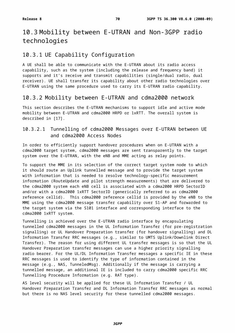
- KUPenc is a key, which shall only be used for the protection of UP traffic with a particular encryption algorithm. This key is derived by UE and eNB from KeNB, as well as an identifier for the encryption algorithm.
- KRRCint is a key, which shall only be used for the protection of RRC traffic with a particular integrity algorithm. KRRCint is derived by UE and eNB from KeNB, as well as an identifier for the integrity algorithm.
- KRRCenc is a key, which shall only be used for the protection of RRC traffic with a particular encryption algorithm. KRRCenc is derived by UE and eNB from KeNB as well as an identifier for the encryption algorithm.
USIM / AuC
UE / MME
UE / ASMEKASME
K
CK, IK
KeNB-UP-enc KeNB-RRC- int
KeNBKNAS int
UE / HSS
UE / eNB
KNAS enc
KeNB-RRC-enc
Figure 14.1-1: Key Hierarchy
COUNT-C reusing avoidance for the same radio bearer identity in RRC_CONNECTED mode without KeNB change is left to eNB implementation e.g. by using intra-cell handover, smart management of radio bearer identities or triggering a transition to RRC_IDLE.
In case of HFN de-synchronisation in RRC_CONNECTED mode between the UE and eNB, the UE is pushed to IDLE.
14.2 Security termination pointsThe table below describes the security termination points.
3GPP
3GPP TS 36.300 V8.6.0 (2008-09)70Release 8
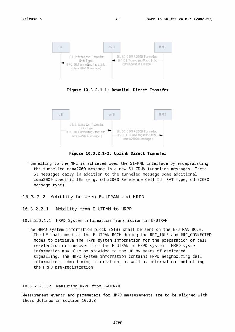
Table 14.2-1 Security Termination Points
Ciphering Integrity Protection
NAS Signalling Required and terminated in MME Required and terminated in MME
U-Plane Data Required and terminated in eNB Not Required (NOTE 1)
RRC Signalling (AS) Required and terminated in eNB Required and terminated in eNB
MAC Signalling (AS) Not required (NOTE 2) Not required (NOTE 2)NOTE 1: Integrity protection for U-Plane is not required and thus it is not supported between UE and Serving
Gateway or for the transport of user plane data between eNB and Serving Gateway on S1 interface.NOTE 2: SA3 needs to further study on whether buffer status reports from UEs to the eNBs in MAC layer need to
be protected.
14.3 State Transitions and Mobility
14.3.1 RRC_IDLE to RRC_CONNECTEDAs a general principle, on RRC_IDLE to RRC_CONNECTED transitions, RRC protection keys and UP protection keys shall be generated while keys for NAS protection as well as higher layer keys are assumed to be already available in the MME. These higher layer keys may have been established in the MME as a result of an AKA run, or as a result of a transfer from another MME during handover or idle mode mobility.
14.3.2 RRC_CONNECTED to RRC_IDLEOn RRC_CONNECTED to RRC_IDLE transitions, eNBs shall delete the keys they store such that state for idle mode UEs only has to be maintained in MME. It is also assumed that eNB does no longer store state information about the corresponding UE and deletes the current keys from its memory. In particular, on connected to idle transitions:
- The eNB deletes KeNB , KRRCenc , KRRCint and KUPenc
- MME keeps KASME stored.
14.3.3 Intra E-UTRAN MobilityThe key hierarchy does not allow, as is, explicit key updates, but RRC and UP keys are derived based on the algorithm identifiers, KeNB, and certain dynamic parameters (e.g. C-RNTI), which result as new RRC and UP keys at every handover (FFS for intra-eNB):.
- Source eNB and UE independently create KeNB* from the current KeNB;
- KeNB* is given to Target eNB during the HO preparation phase;
- Both Target eNB and UE derive the new KeNB based on KeNB* and C-RNTI allocated by the target eNB to UE.
The handling of HFN and PDCP SN at handover depends on the type of radio bearer:
- SRB: HFN and PDCP SN are reset.
- RLC-UM bearers: HFN and PDCP SN are reset.
- RLC-AM bearers: PDCP SN and HFN are maintained (10.1.2.3).
NOTE: COUNT-C reusing avoidance is left to network implementation.
3GPP
3GPP TS 36.300 V8.6.0 (2008-09)71Release 8
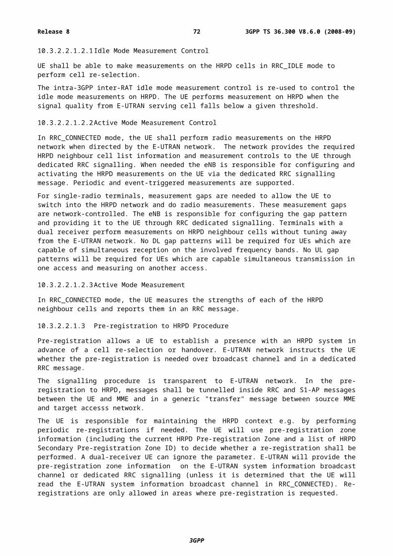
14.4 AS Key Change in RRC_CONNECTEDIf AS Keys (KUPenc , KRRCint and KRRCenc) need to be changed in RRC_CONNECTED, something along the line of an intra-cell handover is used (FFS).
14.5 Security InterworkingIf user plane ciphering is activated in the source RAN, it shall remain activated in the target RAN.
Inter-RAT handover from UTRAN to E-UTRAN is only supported after activation of integrity protection in UTRAN. Security may be activated using null algorithms. If ciphering was not running in UTRAN, it will be activated at handover to E-UTRAN.
For E-UTRAN to UTRAN/GERAN mobility, the MME shall derive and transfer to the SGSN a confidentially key and an integrity key from KASME. Based on this information, the SGSN can in turn derive appropriate keys to be used in the target RAN.
Similarly for UTRAN/GERAN to E-UTRAN mobility, the SGSN shall derive and transfer to the MME a confidentially key and an integrity key. Based on this information, the MME can in turn derive KASME.
15 MBMSFor MBMS, the following definitions are introduced:
MBSFN Synchronization Area: an area of the network where all NodeBs/eNodeBs can be synchronized and perform MBSFN transmissions. MBSFN Synchronization Areas are capable of supporting one or more MBSFN Areas. On a given frequency layer, a NodeB/eNodeB can only belong to one MBSFN Synchronization Area. MBSFN Synchronization Areas are independent from the definition of MBMS Service Areas
MBSFN Transmission or a transmission in MBSFN mode: a simulcast transmission technique realised by transmission of identical waveforms at the same time from multiple cells. An MBSFN Transmission from multiple cells within the MBSFN Area is seen as a single transmission by a UE.
MBSFN Area: a MBSFN Area consists of a group of cells within an MBSFN Synchronization Area of a network, which are co-ordinated to achieve a MBSFN Transmission. A cell within an MBSFN Synchronization Area may form part of multiple MBSFN Areas, each characterized by different transmitted content and participating set of cells.
Figure 15-1: MBMS Definitions
MBSFN Area Transmitting and Advertising Cell: A cell within a MBSFN Area which is contributing to the MBSFN Transmission and advertises within the cell the availability of the MBSFN Transmission.
3GPP
3GPP TS 36.300 V8.6.0 (2008-09)72Release 8
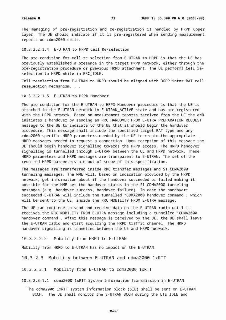
MBSFN Area Transmitting-Only Cell: A cell within a MBSFN Area which is contributing to the MBSFN Transmission but does not advertise within the cell the availability of the MBSFN Transmission. The need for this type of cell is FFS.
MBSFN Area Reserved Cell: A cell within a MBSFN Area which does not contribute to the MBSFN Transmission. The cell may be allowed to transmit for other services but at restricted power on the resource allocated for the MBSFN transmission e.g. PTP for users at the centre of the cell.
15.1 GeneralIn E-UTRAN, MBMS can be provided on a frequency layer dedicated to MBMS (set of cells dedicated to MBMS transmission i.e. set of "MBMS dedicated cells") and/or on a frequency layer shared with non-MBMS services (set of cells supporting both unicast and MBMS transmissions i.e. set of "Unicast/MBMS mixed cells"). In both cases, single frequency network mode of operation is possible for MBMS transmission (MBSFN).
MBMS reception is possible for UEs in RRC_CONNECTED or RRC_IDLE states. Whenever receiving MBMS services, a user shall be notified of an incoming call, and originating calls shall be possible.
15.1.1 E-MBMS Logical Architecture
Figure 15.1.1-1: E-MBMS Logical Architecture
Figure 15.1.1-1 depicts the E-MBMS Logical Architecture.
NOTE: Additional horizontal interfaces e.g. MCE to MCE is FFS.
Multi-cell/multicast Coordination Entity (MCE)
The MCE is a logical entity – this does not preclude the possibility that it may be part of another network element – whose functions are the allocation of the radio resources used by all eNBs in the MBSFN area for multi-cell MBMS transmissions using MBSFN operation. Besides allocation of the time/ frequency radio resources this also includes deciding the further details of the radio configuration e.g. the modulation and coding scheme. The MCE is involved in MBMS Session Control Signalling. The MCE does not perform UE - MCE signalling.
E-MBMS Gateway (MBMS GW)
The MBMS GW is a logical entity – this does not preclude the possibility that it may be part of another network element – that is present between the BMSC and eNBs whose principal functions is the sending/broadcasting of MBMS packets with the SYNC protocol to each eNB transmitting the service. The MBMS GW hosts the PDCP layer of the user plane and uses IP Multicast as the means of forwarding MBMS user data to the eNB. The MBMS GW performs MBMS Session Control Signalling (Session start/stop) towards the E-UTRAN.
Control Plane Interfaces
3GPP
3GPP TS 36.300 V8.6.0 (2008-09)73Release 8
“M3” Interface: MCE – MBMS GW
An Application Part is defined for this interface between E-MBMS Gateway and MCE. This application part allows for MBMS Session Control Signalling on EPS bearer level (i.e. does not convey radio configuration data). The procedures comprise e.g. MBMS Session Start and Stop. SCTP is used as signalling transport i.e. Point-to-Point signalling is applied.
“M2” Interface: MCE – eNB
An Application Part is defined for this interface, which conveys at least radio configuration data for the multi-cell transmission mode eNBs and Session Control Signalling. SCTP is used as signalling transport i.e. Point-to-Point signalling is applied.
User Plane Interface
“M1” Interface: MBMS GW – eNB
This interface is a pure user plane interface. Consequently no Control Plane Application Part is defined for this interface. IP Multicast is used for point-to-multipoint delivery of user packets for both single cell and multi-cell transmission.
Deployment consideration
It is not precluded that M3 interface can be terminated in eNBs. In this case MCE is considered as being part of eNB. Therefore M2 does not exist in this scenario. This is depicted in Figure 15.1.1-2 which depicts two envisaged deployment alternatives. In the scenario depicted on the left MCE is deployed in a separate node. In the scenario on the right MCE is part of the eNBs. These eMBMS architecture deployment alternatives shall be applicable to both multi-cell and single cell transmission mode.
.
Figure 15.1.1-2: eMBMS Architecture deployment alternatives
15.1.2 E-MBMS User Plane Protocol ArchitectureThe overall U-plane architecture of content synchronization is shown in Figure 15.1-1. This architecture is based on the functional allocation for Unicast and the SYNC protocol layer is defined additionally on transport network layer to support content synchronization mechanism.
3GPP
MBMS CP
MBMSUP
eBMSCPDNGateway
ContentsProvider
eNB eNB
M1
M2
M3
MBMS CP
MBMSUP
eBMSCPDNGateway
ContentsProvider
eNB eNB
M1M3
SGmb SGimb SGmb SGimb
MCE
F4 F2
MBMS MBMS
eBMSCPDNGateway
ContentsProvider
eNB eNB
M1
M2
M3
MBMS MBMS
eBMSCPDNGateway
ContentsProvider
eNB eNB
M1
SGmb SGimb SGmb SGimb
MCE
MCE MCE
E- MBMS GW
3GPP TS 36.300 V8.6.0 (2008-09)74Release 8
Figure 15.1.2-1: The overall u-plane architecture of the MBMS content synchronization
The SYNC protocol is defined as a protocol to carry additional information that enable eNBs to identify the timing for radio frame transmission and detect packet loss. The SYNC protocol is applicable to DL and may be specified as a part of GTP-U, or as an independent protocol.
If PDCP (Header Compression) is used, it is located in the E-MBMS GW for both multi-cell and single-cell transmission.
Complying with the content synchronization mechanism is required for an eNB distributing a MBMS service for Multi-Cell transmission. An eNB transmitting a service in single cell only should not be required to comply with the stringent timing requirements indicated by SYNC protocol.
15.2 MBMS CellsAn E-UTRAN cell supporting MBMS is either an MBMS-dedicated cell or an MBMS/Unicast-mixed cell.
15.2.1 MBMS-dedicated cellWhen a cell belongs to a frequency layer dedicated to MBMS transmission:
- MTCH and MCCH are mapped on MCH or DL-SCH (FFS) for p-t-m transmission;
- No uplink;
- No counting mechanism in another (unicast) cell supported;
- No support for unicast data transfer in the cell;
- The occurrence of paging messages on the frequency layer dedicated to MBMS transmission is FFS:
- If paging messages were allowed, the UE could answer in a non-E-UTRA cell e.g. UTRA cell (FFS);
15.2.2 MBMS/Unicast-mixed cellWhen a cell does not belong to a frequency layer dedicated to MBMS transmission:
- MTCH and MCCH are mapped on MCH or DL-SCH for p-t-m transmission;
- Transmission of both unicast and MBMS in the cell is done in a co-ordinated manner.
3GPP
3GPP TS 36.300 V8.6.0 (2008-09)75Release 8
15.3 MBMS Transmission
15.3.1 GeneralTransmission of MBMS in E-UTRAN is either a single-cell transmission or a multi-cell transmission. In both cases, MCCH terminates at the eNB.
15.3.2 Single-cell transmissionSingle-cell transmission of MBMS is characterized by:
- MBMS is transmitted only on the coverage of a specific cell;
- Combining of MBMS transmission from multiple cells is not supported;
- MTCH and MCCH are mapped on DL-SCH for p-t-m transmission;
- Scheduling is done by the eNB;
- Multiple UEs can be allocated dedicated uplink feedback channels identical to those used in unicast transmission, which enables them to report HARQ Ack/Nack and CQI. Where such a feedback mechanism is configured, AMC is applied, and HARQ retransmissions are made on DL-SCH using a group (service specific) RNTI in a time frame that is co-ordinated with the original MTCH transmission. All UEs are able to receive the retransmissions and combine them with the original transmissions at the HARQ level.
- UEs that are allocated a dedicated uplink feedback channel are in RRC_CONNECTED state.
- To avoid unnecessary MBMS transmission on MTCH in a cell where there is no MBMS user, MCCH may announce only the availability of MBMS service(s) and the network can detect the presence in a cell of at least one MBMS user interested in the MBMS service (e.g. by polling or through UE service request) before starting the transmission on MTCH. It is FFS whether or not it is needed to count to a greater granularity the number of UEs in a cell interested in an MBMS service.
For single-cell transmission, an eNB is not required to comply with the stringent timing requirements indicated by SYNC protocol. The following principles still applies for the single transmission:
1. An E-MBMS GW sends/broadcasts MBMS packet with the SYNC protocol to each eNB transmitting the service.
2. The SYNC protocol provides additional information so that the eNBs identify the transmission radio frame(s). The E-MBMS GW does not need accurate knowledge of radio resource allocation in terms of exact time division (e.g. exact start time of the radio frame transmission).
3. The segmentation/concatenation is needed for MBMS packets and should be totally up to the RLC/MAC layer in eNB, without taking into account any indication in the SYNC protocol.
15.3.3 Multi-cell transmissionMulti-cell transmission of MBMS is characterized by:
- Synchronous transmission of MBMS within its MBSFN Area;
- Combining of MBMS transmission from multiple cells is supported;
- MTCH and MCCH are mapped on MCH for p-t-m transmission;
- The MBSFN Synchronization Area, the MBSFN Area, and the MBSFN Transmitting, Advertising, and Reserved cells are semi-statically configured e.g. by O&M.
- Scheduling of each MCH is done by the MCE.
- AMC based on non-AS level feedback is FFS.
3GPP
3GPP TS 36.300 V8.6.0 (2008-09)76Release 8
A carrier frequency may support more than one MCH, where the physical resource allocation to a specific MCH is made by specifying a pattern of subframes, not necessarily adjacent in time, to that MCH. This pattern is called a MCH Subframe Allocation Pattern (MSAP). Multiple MBMS services can be mapped to the same MCH and one MCH contains data belonging to only one MBSFN Area. Whether there is a 1-to-1 mapping between MCH and MBSFN Area is FFS. The MSAP for every MCH carrying MTCH is signalled on MCCH. At such an MSAP occasion:
- The eNB applies MAC multiplexing of different MTCH's to be transmitted on this MCH. The transmission order of MTCHs is signalled (FFS whether implicitly or explicitly) in the MCCH;
- Dynamic scheduling information can be provided in the MSAP occasion to assist the UE in choosing which subframes it needs to receive, both when services are multiplexed onto the MCH and when only a single service is transmitted on the MCH. It is FFS how the scheduling information is carried (e.g. in a MAC control element, or a separate logical channel MSCH). The dynamic scheduling information carries the mapping of MTCHs to the sub-frames of the associated MSAP occasion. This mapping is based on the indexing of sub-frames belonging to one MSAP occasion.
The content synchronization for multi-cell transmission is provided by the following principles:
1. All eNBs in a given MBSFN Synchronization Area have a synchronised radio frame timing such that the radio frames are transmitted at the same time.
2. All eNBs have the same configuration of RLC/MAC/PHY for each MBMS service, and identical information (e.g. time information, transmission order/priority information) such that synchronized dynamic scheduling in the eNBs is ensured. These are indicated in advance by the MCE.
3. An E-MBMS GW sends/broadcasts MBMS packet with the SYNC protocol to each eNB transmitting the service.
4. The SYNC protocol provides additional information so that the eNBs identify the transmission radio frame(s). The E-MBMS GW does not need accurate knowledge of radio resource allocation in terms of exact time division (e.g. exact start time of the radio frame transmission).
5. eNB buffers MBMS packet and waits for the transmission timing indicated in the SYNC protocol.
6. The segmentation/concatenation is needed for MBMS packets and should be totally up to the RLC/MAC layer in eNB.
7. The SYNC protocol provides means to detect packet loss(es) and supports a recovery mechanism robust against loss of consecutive PDU packets (MBMS Packets with SYNC Header).
8. For the packet loss case the transmission of radio blocks potentially impacted by the lost packet should be muted.
9. The mechanism supports indication or detection of MBMS data burst termination (e.g. to identify and alternately use available spare resources related to pauses in the MBMS PDU data flow).
15.3.4 MBMS Reception StatesUEs that are receiving MTCH transmissions and are taking part in at least one MBMS feedback scheme will be in RRC_CONNECTED state. UEs receiving MTCH transmissions without taking part in an MBMS feedback mechanism can be in RRC_IDLE or RRC_CONNECTED state.
For the reception of single-cell transmission of MTCH, an eNB can require a UE to be in RRC_CONNECTED state. The signalling by which a UE is triggered to move to RRC_CONNECTED state solely for single-cell reception purposes is carried on MCCH.
15.3.5 MCCH StructureThe following principles govern the MCCH structure:
- BCCH indicates the scheduling of one or two Primary MCCH (one for single cell transmission on DL-SCH, one for multi-cell transmission on MCH) where the Primary MCCH on MCH can also point to additional Secondary MCCH(s) on MCH if any.
3GPP
3GPP TS 36.300 V8.6.0 (2008-09)77Release 8
NOTE: the need for Secondary MCCH(s) when the Primary MCCH is mapped on DL-SCH is FFS.
- BCCH only points to the resources where the Primary MCCH(s) can be found i.e. it does not indicate the availability of the services.
- The primary MCCH is sent on DL-SCH for single cell transmission and on MCH for multi-cell transmission on an MBSFN area.
- Multiple overlapping MTCH-MBSFN areas can result in multiple MCCHs, for which using different MBSFN areas should be possible (using Secondary MCCHs).
- The MCCH-MBSFN area is not necessarily the same as the MTCH-MBSFN area i.e. MCCH can be either on a different MCH than the MCH carrying “advertised” MTCH, or multiplexed on the same MCH as the one carrying “advertised” MTCH.
15.4 Service ContinuityAs combinations of the possible MBMS cell types and transmission modes, various deployment scenarios come into question. Among them, E-UTRAN provides the necessary optimization mechanisms to support seamless MBMS continuity between:
1) MBSFN and single-cell transmission on a shared frequency layer;
2) MBSFN on a dedicated frequency layer and single-cell transmission on a shared frequency layer;
3) Cells providing single-cell transmission on a shared frequency layer.
For the reception of single-cell transmission of MTCH, UEs that are receiving MBMS service(s) in RRC_CONNECTED state (either directed to the state to receive the MBMS service or in the state already for other reasons and the eNB is aware that the UE is receiving the particular MBMS service(s)), can be provided with target cell MTCH information for these services via the handover related signalling. The serving eNB will trigger the target eNB to prepare for the handover e.g. to obtain the MBMS service if necessary.
UEs that are receiving MBMS service(s) in RRC_IDLE state performing cell reselection or are in RRC_CONNECTED state and which do not receive target cell information as part of handover signalling, should obtain target cell MTCH information from the target cell MCCH or, if supported, serving cell MCCH information (FFS). If the UE was in RRC_CONNECTED state and the source eNB was aware that it is receiving the particular MBMS service(s) the serving eNB could trigger the target eNB to prepare for the handover e.g. to obtain the MBMS service if necessary.
15.5 Network sharingNetwork sharing of MBMS resources among multiple operators of the same country is supported, with focus on, but not limited to, sharing of a dedicated-carrier MBSFN. MBMS network sharing shall not require unicast network sharing. Unicast mobility shall not be affected by the sharing of MBMS resources by operators.
NOTE: it is FFS whether this is based on dual-receiver solutions.
15.6 Network Functions for Support of MultiplexingConsiderable gain in radio resource efficiency can be achieved by multiplexing several E-MBMS services on a single MCH. The services that share the resources are called E-MBMS Service Multiplex. The amount of common radio resources allocated to such an E-MBMS Service Multiplex can be smaller than the sum of radio resources, which would need to be allocated for the individual services without multiplexing. This represents the statistical multiplexing gain.
The entity managing the E-MBMS Service Multiplex e.g. deciding which services are to be multiplexed is FFS. The duration of each E-MBMS service may be different, so there is may be a need to manage the Service Multiplex dynamically, i.e. addition or removal of services into/from the E-MBMS Service Multiplex. The MCE allocates the optimal amount of resources to multiplexed services, using service related information. MBSFN transmission is ensured by identical multiplexing of the services within the MBMS-GW or different eNBs. The location of the multiplexing function is FFS.
3GPP
3GPP TS 36.300 V8.6.0 (2008-09)78Release 8
These functions are supported by respective signalling and by the SYNC protocol on M1, the details are FFS.
15.7 Procedures
15.7.1 Procedures for Broadcast mode
15.7.1.1 Session Start procedure
The purpose of the MBMS Session Start procedure is to request the E-UTRAN to notify UEs about an upcoming MBMS Session of a given MBMS Bearer Service and to establish an MBMS SAE bearer for this MBMS Session. The MBMS Session Start procedure is triggered by the EPC.
Figure 15.7.1.1-1. Session Start procedure
1. The MBMS GW entity sends MBMS session start request message to the MCE(s) controlling eNBs in the targeted MBMS service area. The message includes the IP multicast address and session attributes.
2. MCE confirms the reception of the MBMS Session Start request to the MBMS GW. It is FFS whether this message is transmitted after message 4.
3. MCE sends the MBMS Session Start message to the eNBs in the targeted MBMS service area. In addition to the session attributes this message provides radio bearer configuration for MBSFN transmission.
4. eNB confirms the reception of the MBMS Session Start message.
5. eNB sends the MBMS Session Start message to UEs. The location of the message is FFS, other positions are after messages 6 or 7. The message details are FFS.
6. eNB joins the IP multicast group to receive the MBMS User Plane data.
7. eNB sends the MBMS data to radio interface at the determined time.
3GPP
3GPP TS 36.300 V8.6.0 (2008-09)79Release 8
15.7.1.2 Session Stop procedure
The MBMS Session Stop procedure is to request the E-UTRAN to notify UEs about the end of a given MBMS Session and to release the corresponding MBMS SAE bearer this MBMS Session. The MBMS Session Stop procedure is triggered by the EPC.
Figure 15.7.1.2-1. Session Stop procedure
1. The MBMS GW entity sends MBMS session stop request message to the MCE(s) controlling eNBs in the targeted MBMS service area.
2. MCE confirms the reception of the MBMS Session stop request to the MBMS GW.
3. MCE forwards the MBMS Session stop message to the eNBs in the targeted MBMS service area.
4. eNB confirms the reception of the MBMS Session stop message.
5. eNB sends the MBMS Session stop message to UEs. The message details are FFS.
6. The corresponding SAE bearer is released, and eNB leaves the the IP multicast group.
16 Radio Resource Management aspectsThe purpose of radio resource management (RRM) is to ensure the efficient use the available radio resources and to provide mechanisms that enable E-UTRAN to meet radio resource related requirements identified in sub-clause 10 of 3GPP TR 25.913 [2]. In particular, RRM in E-UTRAN provides means to manage (e.g. assign, re-assign and release) radio resources taking into account single and multi-cell aspects.
16.1 RRM functions
16.1.1 Radio Bearer Control (RBC)The establishment, maintenance and release of Radio Bearers involve the configuration of radio resources associated with them. When setting up a radio bearer for a service, radio bearer control (RBC) takes into account the overall resource situation in E-UTRAN, the QoS requirements of in-progress sessions and the QoS requirement for the new service. RBC is also concerned with the maintenance of radio bearers of in-progress sessions at the change of the radio resource situation due to mobility or other reasons. RBC is involved in the release of radio resources associated with radio bearers at session termination, handover or at other occasions.
3GPP
3GPP TS 36.300 V8.6.0 (2008-09)80Release 8
RBC is located in the eNB.
16.1.2 Radio Admission Control (RAC)The task of radio admission control (RAC) is to admit or reject the establishment requests for new radio bearers. In order to do this, RAC takes into account the overall resource situation in E-UTRAN, the QoS requirements, the priority levels and the provided QoS of in-progress sessions and the QoS requirement of the new radio bearer request. The goal of RAC is to ensure high radio resource utilization (by accepting radio bearer requests as long as radio resources available) and at the same time to ensure proper QoS for in-progress sessions (by rejecting radio bearer requests when they cannot be accommodated).
RAC is located in the eNB.
16.1.3 Connection Mobility Control (CMC)Connection mobility control (CMC) is concerned with the management of radio resources in connection with idle or connected mode mobility. In idle mode, the cell reselection algorithms are controlled by setting of parameters (thresholds and hysteresis values) that define the best cell and/or determine when the UE should select a new cell. Also, E-UTRAN broadcasts parameters that configure the UE measurement and reporting procedures. In connected mode, the mobility of radio connections has to be supported. Handover decisions may be based on UE and eNB measurements. In addition, handover decisions may take other inputs, such as neighbour cell load, traffic distribution, transport and hardware resources and Operator defined policies into account.
CMC is located in the eNB.
16.1.4 Dynamic Resource Allocation (DRA) - Packet Scheduling (PS)The task of dynamic resource allocation (DRA) or packet scheduling (PS) is to allocate and de-allocate resources (including buffer and processing resources and resource blocks (i.e. chunks)) to user and control plane packets. DRA involves several sub-tasks, including the selection of radio bearers whose packets are to be scheduled and managing the necessary resources (e.g. the power levels or the specific resource blocks used). PS typically takes into account the QoS requirements associated with the radio bearers, the channel quality information for UEs, buffer status, interference situation, etc. DRA may also take into account restrictions or preferences on some of the available resource blocks or resource block sets due to inter-cell interference coordination considerations.
DRA is located in the eNB.
16.1.5 Inter-cell Interference Coordination (ICIC)Inter-cell interference coordination has the task to manage radio resources (notably the radio resource blocks) such that inter-cell interference is kept under control. ICIC is inherently a multi-cell RRM function that needs to take into account information (e.g. the resource usage status and traffic load situation) from multiple cells. The preferred ICIC method may be different in the uplink and downlink.
ICIC is located in the eNB.
16.1.6 Load Balancing (LB)Load balancing has the task to handle uneven distribution of the traffic load over multiple cells. The purpose of LB is thus to influence the load distribution in such a manner that radio resources remain highly utilized and the QoS of in-progress sessions are maintained to the extent possible and call dropping probabilities are kept sufficiently small. LB algorithms may result in hand-over or cell reselection decisions with the purpose of redistribute traffic from highly loaded cells to underutilized cells.
LB is located in the eNB.
16.1.7 Inter-RAT Radio Resource ManagementInter-RAT RRM is primarily concerned with the management of radio resources in connection with inter-RAT mobility, notably inter-RAT handover. At inter-RAT handover, the handover decision may take into account the
3GPP
3GPP TS 36.300 V8.6.0 (2008-09)81Release 8
involved RATs resource situation as well as UE capabilities and Operator policies. The importance of Inter-RAT RRM may depend on the specific scenario in which E-UTRAN is deployed. Inter-RAT RRM may also include functionality for inter-RAT load balancing for idle and connected mode UEs.
16.1.8 Subscriber Profile ID for RAT/Frequency PriorityThe RRM strategy in E-UTRAN may be based on user specific information.
The Subscriber Profile ID for RAT/Frequency Priority (SPID) parameter received by the eNB via the S1 interface is an index referring to user information (e.g. mobility profile, service usage profile and roaming restrictions). The information is UE specific and applies to all its Radio Bearers.
This index is mapped by the eNB to locally defined configuration in order to apply specific RRM strategies (e.g. to define RRC_IDLE mode priorities and control inter-RAT/inter frequency handover in RRC_CONNECTED mode).
16.2 RRM architecture
16.2.1 Centralised Handling of certain RRM Functions
16.2.2 De-Centralised RRMHistorical information about the UE is transferred between the eNBs over the X2 interface during the handover preparation procedure. For instance, an activity level description of the UE in the source eNB is transferred to the target eNB.
16.2.3 Load balancing control
17 RF aspects
17.1 Spectrum deployments
18 UE capabilitiesRRC signalling carries RRC capability and NAS signalling carries NAS capability. Some capability information is stored in the EPC. In the uplink, some capability information may be sent early in e.g. RRC_CONNECTION_REQUEST. In the downlink, inquiry procedure of the UE capability may be supported.
19 S1 Interface
19.1 S1 User plane The S1 user plane interface (S1-U) is defined between the eNB and the S-GW. The S1-U interface provides non guaranteed delivery of user plane PDUs between the eNB and the S-GW. The user plane protocol stack on the S1 interface is shown in Figure 19.1-1. The transport network layer is built on IP transport and GTP-U is used on top of UDP/IP to carry the user plane PDUs between the eNB and the S-GW.
3GPP
3GPP TS 36.300 V8.6.0 (2008-09)82Release 8
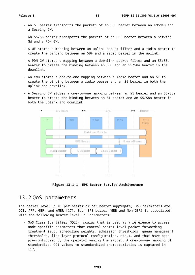
Figure 19.1-1: S1 Interface User Plane (eNB - S-GW)
19.2 S1 Control PlaneThe S1 control plane interface (S1-MME) is defined between the eNB and the MME. The control plane protocol stack of the S1 interface is shown on Figure 19.2-1. The transport network layer is built on IP transport, similarly to the user plane but for the reliable transport of signalling messages SCTP is added on top of IP. The application layer signalling protocol is referred to as S1-AP (S1 Application Protocol).
Figure 19.2-1: S1 Interface Control Plane (eNB-MME)
The SCTP layer provides the guaranteed delivery of application layer messages.
In the transport IP layer point-to-point transmission is used to deliver the signalling PDUs.
A single SCTP association per S1-MME interface instance shall be used with one pair of stream identifiers for S1-MME common procedures. Only a few pairs of stream identifiers should be used for S1-MME dedicated procedures. The upper limit for the number of stream identifiers for dedicated procedures is FFS and will be decided during the stage 3 work.
MME communication context identifiers that are assigned by the MME for S1-MME dedicated procedures and eNB communication context identifiers that are assigned by the eNB for S1-MME dedicated procedures shall be used to distinguish UE specific S1-MME signalling transport bearers. The communication context identifiers are conveyed in the respective S1-AP messages.
3GPP
3GPP TS 36.300 V8.6.0 (2008-09)83Release 8
19.2.1 S1 Interface FunctionsNote: The following list of S1 functions reflects the status of agreements in RAN3, might be extended in
forthcoming meetings.
- EPS Bearer Service Management function:
- Setup, Modify, release.
- Mobility Functions for UEs in ECM-CONNECTED:
- Intra-LTE Handover;
- Inter-3GPP-RAT Handover.
- S1 Paging function:
- NAS Signalling Transport function;
- S1-interface management functions:
- Error indication;
- Reset.
- Network Sharing Function;
- Roaming and Area Restriction Support function;
- NAS Node Selection Function;
- Initial Context Setup Function;
- UE Context Modification Function;
- MME Load balancing Function;
- Location Reporting Function;
- ETWS Message Transmission Function;
- Overload function.
19.2.1.1 S1 Paging function
The paging function supports the sending of paging requests to all cells of the TA(s) the UE is registered.
Paging requests are sent to the relevant eNBs according to the mobility information kept in the UE’s MM context in the serving MME.
19.2.1.2 S1 UE Context Management function
In order to support UEs in ECM-CONNECTED, UE contexts need to be managed, i.e. established and released in the eNodeB and in the EPC to support user individual signalling on S1.
19.2.1.3 Initial Context Setup Function
The Initial Context Setup function supports the establishment of the necessary overall initial UE Context including EPS Bearer context, Security context, roaming restriction, UE capability information, Subscriber Profile ID for RAT/Frequency Priority, UE S1 signalling connection ID, etc. in the eNB to enable fast Idle-to-Active transition.
In addition to the setup of overall initial UE Contexts, Initial Context Setup function also supports the piggy-backing of the corresponding NAS messages. Initial Context Setup is initiated by the MME.
3GPP
3GPP TS 36.300 V8.6.0 (2008-09)84Release 8
19.2.1.3a UE Context Modification Function
The UE Context Modification function supports the modification of UE Context in eNB for UEs in active state.
19.2.1.4 Mobility Functions for UEs in ECM-CONNECTED
19.2.1.4.1 Intra-LTE Handover
The Intra-LTE-Handover function supports mobility for UEs in ECM-CONNECTED and comprises the preparation, execution and completion of handover via the X2 and S1 interfaces.
19.2.1.4.2 Inter-3GPP-RAT Handover
The Inter-3GPP-RAT Handover function supports mobility to and from other 3GPP-RATs for UEs in ECM-CONNECTED and comprises the preparation, execution and completion of handover via the S1 interface.
19.2.1.5 EPS Bearer Service Management function
The EPS Bearer Service management function is responsible for establishing, modifying and releasing E-UTRAN resources for user data transport once a UE context is available in the eNB. The establishment and modification of E-UTRAN resources is triggered by the MME and requires respective QoS information to be provided to the eNB. The release of E-UTRAN resources is triggered by the MME either directly or following a request received from the eNB (optional).
NOTE: Whether EPS bearer related NAS messages are included in S1AP EPS Bearer Management procedures piggybacking or if NAS messages are sent with S1-AP Direct Transfer is FFS:
19.2.1.6 NAS Signalling Transport function
The NAS Signalling Transport function provides means to transport a NAS message (e.g. for NAS mobility management) for a specific UE on the S1 interface.
19.2.1.7 NAS Node Selection Function
The interconnection of eNBs to multiple MME/Serving S-GWs is supported in the LTE/SAE architecture. Therefore a NAS node selection function is located in the eNB to determine the MME association of the UE, based on the UE’s temporary identifier, which was assigned to the UE by the MME.
This functionality is located in the eNB only and enables proper routing via the S1 interface. On S1, no specific procedure corresponds to the NAS Node Selection Function.
19.2.1.8 S1-interface management functions
The S1-interface management functions provide
- means to ensure a defined start of S1-interface operation (reset)
- means to handle different versions of application part implementations and protocol errors (error indication)
19.2.1.9 MME Load balancing Function
MME Load balancing is the function which achieves load-balanced MMEs with respect to their processing capacity within a pool area during system operation. The means to load-balance MMEs is to distribute UEs newly entering the pool to different MMEs in the MME pool. In addition the MME load balancing function is able to achieve equally loaded MMEs within a pool area after the introduction of a new MME and after the removal of a MME from the network.
The support of the MME load balancing function is achieved by indicating the relative MME capacity in the S1 Setup procedure to all eNBs served by the MMEs of the pool area per MME. In order to support the introduction and/or removal of MMEs the MME initiated S1 setup update procedure may be used by the operator indicating relative MME
3GPP
3GPP TS 36.300 V8.6.0 (2008-09)85Release 8
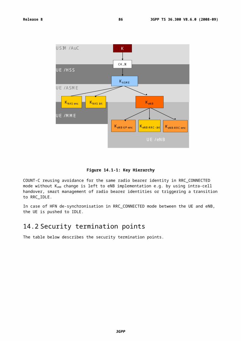
capacity value changes. The indicated relative MME capacity steers the UE assignment for UEs newly entering the MME pool.
19.2.1.10 Location Reporting Function
The Location Reporting function supports the MME requests to the eNB to report the location information of the UE.
19.2.1.11 Warning Message Transmission function
The warning message transmission function provides means to transfer warning message via S1 interface.
19.2.1.12 Overload Function
The overload function comprises the signalling means:
- to indicate to a proportion of eNBs that the serving MME is overloaded
- to indicate to the eNBs that the serving MME is back in the "normal operation mode"
19.2.2 S1 Interface Signalling ProceduresNote: The following list of S1 procedures reflects the status of agreements in RAN3, might be extended in
forthcoming meetings.
- EPS Bearer signalling procedures:
- EPS Bearer Setup procedure;
- EPS Bearer Modification procedure;
- EPS Bearer Release procedure (MME initiated);
- EPS Bearer Release procedure (eNB initiated).
- Handover signalling procedures;
- Handover Preparation procedure;
- Handover Resource Allocation procedure;
- Handover Completion procedure;
- Handover Cancellation procedure.
- Paging procedure;
- NAS transport procedure:
- UL direction (Initial UE Message);
- UL direction (Uplink NAS transport);
- DL direction (Downlink NAS transport).
- Error Indication procedure:
- eNB initiated error indication procedure;
- MME initiated error indication procedure.
- Reset procedure:
- eNB initiated Reset procedure;
- MME initiated Reset procedure.
3GPP
3GPP TS 36.300 V8.6.0 (2008-09)86Release 8
- Initial Context Setup procedure;
- UE Context Modification procedure;
- S1 Setup procedure;
- eNB Configuration Update procedure;
- MME Configuration Update procedure;
- Location Reporting procedures:
- Location Reporting Control procedure;
- Location Report procedure;
- Location Report Failure Indication procedure.
- Overload Start procedure;
- Overload Stop procedure;
- Write Replace Warning procedure.
19.2.2.1 Paging procedure
Figure 19.2.2.1-1: Paging procedure
The MME initiates the paging procedure by sending the PAGING message to each eNB with cells belonging to the tracking area(s) in which the UE is registered. Each eNB can contain cells belonging to different tracking areas, whereas each cell can only belong to one TA.
The paging response back to the MME is initiated on NAS layer and is sent by the eNB based on NAS-level routing information.
19.2.2.2 S1 UE Context Release procedure
The S1 UE Context Release procedure causes the eNB to remove all UE individual signalling resources and the related user data transport resources. This procedure is initiated by the EPC and may be triggered on request of the serving eNB.
3GPP
eNB MME
[S1AP] PAGING
Paging Response (NAS means)
3GPP TS 36.300 V8.6.0 (2008-09)87Release 8
19.2.2.2.1 S1 UE Context Release (EPC triggered)
Figure 19.2.2.2.1-1: S1 UE Context Release procedure (EPC triggered)
- The EPC initiates the UE Context Release procedure by sending the S1 UE Context Release Command towards the E-UTRAN. The eNodeB releases all related signalling and user data transport resources.
- The eNB confirms the S1 UE Context Release activity with the S1 UE Context Release Complete message.
- In the course of this procedure the EPC releases all related resources as well, except context resources in the EPC for mobility management and the default EPS Bearer configuration.
19.2.2.2.2 S1 UE Context Release Request (eNB triggered)
The S1 UE Context Release Request procedure is initiated for E-UTRAN internal reasons and comprises the following steps:
- The eNB sends the S1 UE Context Release Request message to the EPC.
- The EPC triggers the EPC initiated UE context release procedure.
Figure 19.2.2.2.2-1: S1 UE Context Release Request procedure (eNB triggered)and subsequent S1 UE Context Release procedure (EPC triggered)
19.2.2.3 Initial Context Setup procedure
The Initial Context Setup procedure establishes the necessary overall initial UE context in the eNB in case of an Idle-to Active transition. The Initial Context Setup procedure is initiated by the MME.
The Initial Context Setup procedure comprises the following steps:
- The MME initiates the Initial Context Setup procedure by sending INITIAL CONTEXT SETUP REQUEST to the eNB. This message may include general UE Context (e.g. security context, roaming restrictions, UE capability information, UE S1 signalling connection ID, etc.), EPS bearer context (Serving GW TEID, QoS information), and may be piggy-backed with the corresponding NAS message.
3GPP
eNB EPC
[S1AP] S1 UE Context Release Command
[S1AP] S1 UE Context Release Complete
[S1AP] EPC initiated
eNB EPC
[S1AP] S1 UE Context Release Request
[S1AP] S1 UE Context Release Command
[S1AP] S1 UE Context Release Complete
3GPP TS 36.300 V8.6.0 (2008-09)88Release 8
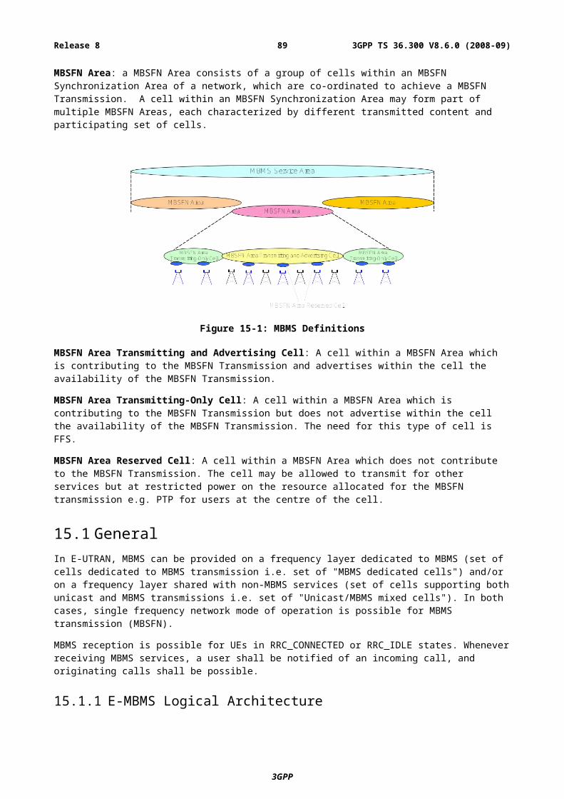
- Upon receipt of INITIAL CONTEXT SETUP REQUEST, the eNB setup the context of the associated UE, and perform the necessary RRC signalling towards the UE, e.g. Radio Bearer Setup procedure.
- The eNB responds with INITIAL CONTEXT SETUP COMPLETE to inform a successful operation, and with INITIAL CONTEXT SETUP FAILURE to inform an unsuccessful operation.
Figure 19.2.2.3-1: Initial Context Setup procedure (highlighted in blue) in Idle-to-Active procedure
19.2.2.3a UE Context Modification procedure
The UE Context Modification procedure enables the MME to modify the UE context in the eNB for UEs in active state. The UE Context Modification procedure is initiated by the MME.
The UE Context Modification procedure comprises the following steps:
- The MME initiates the UE Context Modification procedure by sending UE CONTEXT MODIFICATION REQUEST to the eNB to modify the UE context in the eNB for UEs in active state.
- The eNB responds with UE CONTEXT MODIFICATION RESPONSE to inform a successful operation, and with UE CONTEXT MODIFICATION FAILURE to inform an unsuccessful operation.
3GPP
3GPP TS 36.300 V8.6.0 (2008-09)89Release 8
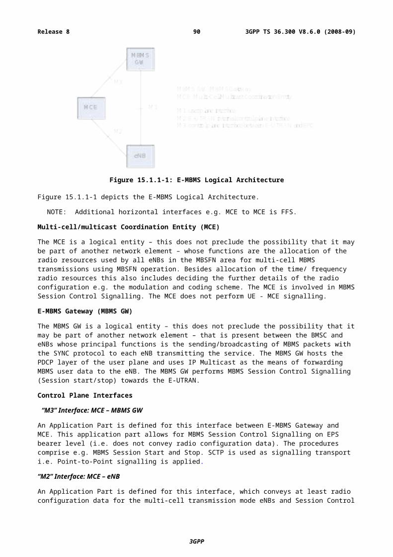
Figure 19.2.2.3a-1: UE Context Modification procedure
19.2.2.4 EPS Bearer signalling procedures
19.2.2.4.1 EPS Bearer Setup procedure
RRC: Radio Bearer Setup
eNB MME UE
S1-AP: SAE BEARER SETUP RESPONSE SAE Bearer Setup List: SAE Bearer ID, TEID eNB SAE Bearer Failed to Setup List: SAE Bearer ID
S1-AP: SAE BEARER SETUP REQUEST SAE Bearer Setup List: SAE Bearer ID, QoS, TEID Serving SAE GW
Figure 19.2.2.4.1-1: EPS Bearer Setup procedure
The EPS Bearer Setup procedure is initiated by the MME to support:
- Assignment of resources to a dedicated EPS bearer.
- Assignment of resources for a default EPS bearer (FFS)
- Setup of S1 Bearer (on S1) and Radio Bearer (on Uu)
The EPS Bearer Setup procedure comprises the following steps:
- The EPS BEARER SETUP REQUEST is sent by the MME to the eNB to setup resources on S1 and Uu for one or several EPS Bearer(s). The EPS BEARER SETUP REQUEST message contains the Serving GW TEID and QoS indicator(s) per EPS bearer within the EPS Bearer Setup List.
- Upon receipt of the EPS BEARER SETUP REQUEST the eNB establishes the Radio Bearer(s) (RRC: Radio Bearer Setup) and resources for S1 Bearers.
- The eNB responds with a EPS BEARER SETUP RESPONSE messages to inform whether the setup of resources and establishment of an EPS Bearer was successful or unsuccessful, with the EPS bearer Setup (EPS Bearer ID , eNB TEID) and the EPS Bearer Failed to Setup list (EPS bearer ID). The eNB also creates the binding between the S1 bearer(s) (DL/UL TEID) and the Radio Bearer(s).
3GPP
3GPP TS 36.300 V8.6.0 (2008-09)90Release 8
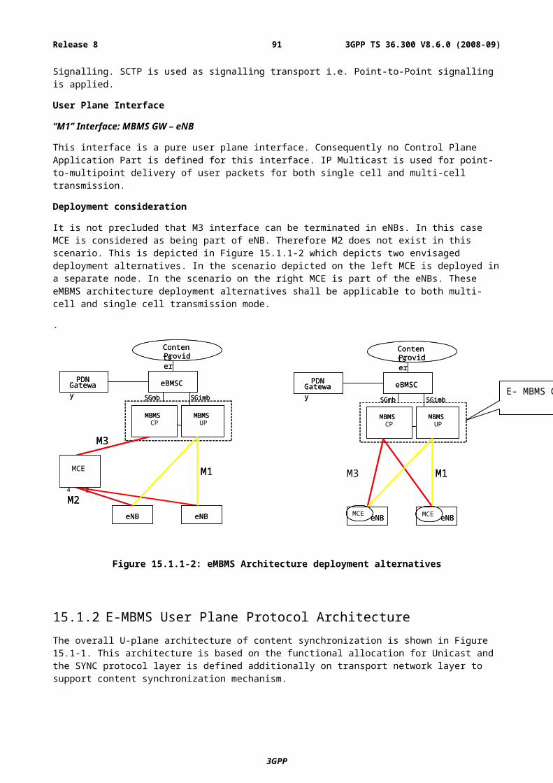
Interactions with UE Context Release Request procedure:
In case of no response from the UE the eNB shall trigger the S1 UE Context Release Request procedure.
19.2.2.4.2 EPS Bearer Modification procedure
Figure 19.2.2.4.2-1: EPS Bearer Modification procedure
The EPS Bearer Modification procedure is initiated by the MME to support the modification of already established EPS Bearer configurations:
- Modify of S1 Bearer (on S1) and Radio Bearer (on Uu)
The EPS Bearer Modification procedure comprises the following steps:
- The EPS BEARER MODIFY REQUEST is sent by the MME to the eNB to modify one or several EPS Bearer(s). The EPS BEARER MODIFY REQUEST message contains the QoS indicator(s) and Serving GW TEID per EPS bearer in the EPS Bearer Modify List.
- Upon receipt of the EPS BEARER MODIFY REQUEST the eNB modifies the Radio Bearer configuration (RRC procedure to modify the Radio bearer).
- The eNB responds with an EPS BEARER MODIFY RESPONSE message to inform whether the EPS Bearer modification has succeeded or not indicating with the EPS bearer Modify list and EPS bearer Failed to Modify list. With EPS Bearer ID(s) in the EPS Bearer Modify List the eNB identifies the EPS bearer(s) successfully modified or failed to modify.
Interactions with UE Context Release Request procedure:
In case of no response from the UE the eNB shall trigger the S1 UE Context Release Request procedure.
19.2.2.4.3 EPS Bearer Release procedure (MME initiated)
3GPP
RRC: Radio Modify Setup
eNB MMEUE
S1-AP: SAE BEARER MODIFY RESPONSE
SAE Bearer Modify List: SAE Bearer ID, eNB TEID
SAE Beaer Failed to Modify List: SAE Bearer ID
S1-AP: SAE BEARER MODIFY REQUEST
SAE Bearer Modify List: SAE Bearer ID, QoS, Serving SAE GW TEID
RRC: Radio Bearer Release
eNB MMEUE
S1-AP: SAE BEARER RELEASE COMPLETE
SAE Bearer Release List: SAE Bearer ID
SAE Bearer Failed to Release List: SAE Bearer ID
S1-AP: SAE BEARER RELEASE COMMAND
SAE Bearer Release List: SAE Bearer ID
3GPP TS 36.300 V8.6.0 (2008-09)91Release 8
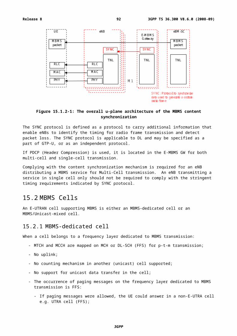
Figure 19.2.2.4.3-1: EPS Bearer Release procedure (MME initiated)
The EPS Bearer Release procedure is initiated by the MME to release resources for the indicated EPS Bearers.
The EPS Bearer Release procedure comprises the following steps:
- The EPS BEARER RELEASE COMMAND is sent by the MME to the eNB to release resources on S1 and Uu for one or several EPS Bearer(s). With the EPS Bearer ID(s) in the EPS bearer Release List contained in EPS BEARER RELEASE COMMAND the MME identifies, the EPS Access Bearer(s) to be released.
- Upon receipt of the EPS BEARER RELEASE COMMAND the eNB releases the Radio Bearers (RRC: Radio bearer release) and S1 Bearers.
- The eNB responds with an EPS BEARER RELEASE COMPLETE message containing EPS bearer Release list and EPS bearer Failed to Release list. With the EPS Bearer IDs in the EPS Bearer Release List/EPS Bearer Failed to Release List the eNB identifies the EPS bearer(s) successfully released or failed to release.
Interactions with UE Context Release Request procedure:
In case of no response or negative response from the UE or in case the eNB cannot successfully perform the release of any of the requested bearers, the eNB shall trigger the S1 UE Context Release Request procedure, except if the eNB has already initiated the procedures associated with X2 Handover.
19.2.2.4.4 EPS Bearer Release procedure (eNB initiated)
Figure 19.2.2.4.4-1: EPS Bearer Release (eNB initiated) procedure
The EPS Bearer Release function enables the E-UTRAN to request the release of resources for one or several EPS Bearers. The eNB initiated EPS Bearer Release procedure comprises the following steps:
- The eNB initiates the EPS Bearer Release procedure by sending the EPS BEARER RELEASE REQUEST message to the MME in order to release of one or more EPS Bearer(s). With the EPS Bearer ID(s) in the EPS Bearer Release List the eNB identifies the EPS bearer(s) requested to be released. The EPS BEARER RELEASE REQUEST message shall include the reason to release the resources for the EPS bearer, for example user inactivity.
- Upon receipt the MME initiates the EPS Bearer Release procedure (EPS BEARER RELEASE COMMAND/ EPS BEARER RELEASE COMPLETE) to request release of resources for the EPS Bearer(s).
19.2.2.5 Handover signalling procedures
Handover signalling procedures support both, inter-eNB handover and inter-RAT handover.
Inter-RAT handovers shall be initiated via the S1 interface.
Inter-eNB handovers shall be initiated via the X2 interface except if any of the following conditions are true:
- there is no X2 between source and target eNB.
3GPP
RRC: Radio Bearer Release
eNB MMEUE
S1-AP: SAE BEARER RELEASE COMPLETE
SAE Bearer Release List: SAE Bearer ID
SAE Bearer Failed to Release List: SAE Bearer ID
S1-AP: SAE BEARER RELEASE COMMAND
SAE Bearer Relase List: SAE Bearer ID
S1-AP: SAE BEARER RELEASE REQUEST
SAE Bearer Release List: SAE Bearer ID
3GPP TS 36.300 V8.6.0 (2008-09)92Release 8
- the source eNB has been configured to initiate handover to the particular target eNB via S1 interface in order to enable the change of an EPC node (MME and/or Serving GW).
- the source eNB has attempted to start the inter-eNB HO via X2 but receives a negative reply from the target eNB with a specific cause value.
NOTE: Handling of cases where the target eNB does not reply is FFS.
Inter-eNB handovers shall be initiated via the S1 interface, if one of the above conditions applies.
NOTE: Affects on Home eNBs should be looked at.
It is foreseen to re-use Handover principles from the Iu interface for inter-eNB handovers which are initiated via the S1 interface.
19.2.2.5.1 Handover Preparation procedure
The Handover preparation procedure is initiated by the source eNB if it determines the necessity to initiate the handover via the S1 interface.
Figure 19.2.2.5.1-1: Handover preparation procedure
The handover preparation comprises the following steps:
- The HANDOVER REQUIRED message is sent to the MME.
- The handover preparation phase is finished upon the reception of the HANDOVER COMMAND in the source eNB, which includes at least radio interface related information (HO Command for the UE), successfully established EPS Bearer(s) and EPS bearer(s) which failed to setup.
- In case the handover resource allocation is not successful (e.g. no resources are available on the target side) the MME responds with the HANDOVER PREPARATION FAILURE message instead of the HANDOVER COMMAND message.
19.2.2.5.2 Handover Resource Allocation procedure
The handover resource allocation comprises the following steps:
3GPP
3GPP TS 36.300 V8.6.0 (2008-09)93Release 8
EMBED Word.Picture.8
S1-AP: HANDOVER REQUEST ACK
Target eNB MME
S1-AP: HANDOVER REQUEST
UE
S1-AP: HANDOVER FAILURE
Figure 19.2.2.5.2-1: Handover resource allocation procedure
- The MME sends the HANDOVER REQUEST message including the EPS Bearer(s) which needs to be setup by the target eNB.
- The target eNB responds with the HANDOVER REQUEST ACK message after the required resources for all accepted EPS Bearers are allocated. The HANDOVER REQUEST ACK message contains successfully established EPS bearer(s), EPS Bearer(s) which failed to setup and radio interface related information (HO Command for the UE), which is later sent transparently via the EPC/CN from the target RAT to the source RAT.
If no resources are available on the target side, the target eNB responds with the HANDOVER FAILURE message instead of the HANDOVER REQUEST ACK message.
19.2.2.5.3 Handover Notification procedure
The Handover Completion for S1 initiated handovers comprises the following steps:
- The HANDOVER NOTIFY message is sent by the target eNB to the MME when the UE has successfully been transferred to the target cell.
EMBED Word.Picture.8
RRC: HANDOVER CONFIRM
Target eNB MME
S1-AP: HANDOVER NOTIFY
UE
Figure 19.2.2.5.3-1: Handover completion procedure
19.2.2.5.4 Handover Cancellation
This functionality is located in the source eNB to allow a final decision regarding the outcome of the handover, i.e. either to proceed or to cancel the handover procedure.
3GPP
3GPP TS 36.300 V8.6.0 (2008-09)94Release 8
EMBED Word.Picture.8
S1-AP: HANDOVER CANCEL ACK
Source eNB MME
S1-AP: HANDOVER CANCEL
Figure 19.2.2.5.4-1: Handover cancellation procedure
- The source eNB sends a HANDOVER CANCEL message to the MME indicating the reason for the handover cancellation.
- The MME confirms the reception of the HANDOVER CANCEL message by returning the HANDOVER CANCEL ACK message.
19.2.2.5.5 Path Switch procedure
The handover completion phase for X2 initiated handovers comprises the following steps:
- The PATH SWITCH message is sent by the target eNB to the MME when the UE has successfully been transferred to the target cell. The PATH SWITCH message includes the outcome of the resource allocation: successfully established EPS Bearer(s).
- The MME responds with the PATH SWITCH ACK message which is sent to the eNB.
- The MME responds with the PATH SWITCH FAILURE message in case a failure occurs in the EPC.
Figure 19.2.2.5.5-1: Path Switch procedure
19.2.2.6 NAS transport procedures
A NAS signalling message is transferred on the S1 interface in both directions. The procedures providing this functionality are
- Initial UE Message procedure (eNB initiated)
- Uplink NAS transport procedure (eNB initiated)
- Downlink NAS transport procedure (MME initiated)
- Downlink NAS non delivery indication procedure
i) Initial UE Message procedure
3GPP
3GPP TS 36.300 V8.6.0 (2008-09)95Release 8
Figure 19.2.2.6-1: Initial UE Message procedure
- The INITIAL UE MESSAGE procedure is initiated by the eNB by sending the INITIAL UE MESSAGE message to the MME. The INITIAL UE MESSAGE contains a NAS message (e.g. Service Request), the UE signalling reference ID and other S1 addressing information.
ii) NAS Transport procedure (eNB initiated).
Figure 19.2.2.6-2: Uplink NAS Transport procedure
- The Uplink NAS Transport procedure is initiated by the eNB by sending the UPLINK NAS TRANSPORT message to the MME. The UPLINK NAS TRANSPORT message contains a NAS message, UE identification and other S1 related addressing information.
iii) NAS Transport procedure (MME initiated)
Figure 19.2.2.6-3: Downlink NAS Transport procedure
- The Downlink NAS Transport procedure is initiated by the MME by sending the DOWNLINK NAS TRANSPORT message to the eNB. The DOWNLINK NAS TRANSPORT contains a NAS message, UE identification and other S1 related addressing information.
iv) Downlink NAS non delivery procedure
3GPP
3GPP TS 36.300 V8.6.0 (2008-09)96Release 8
eNB MME
S1-AP: DOWNLINK NAS NON DELIVERY INDICATION
Figure 19.2.2.6-4: Downlink NAS Non Delivery Indication procedure
- When the eNB decides to not start the delivery of a NAS message that has been received from MME, it shall report the non-delivery of this NAS message by sending a DOWNLINK NAS NON DELIVERY INDICATION message to the MME including the non-delivered NAS message and an appropriate cause value.
19.2.2.7 S1 interface Management procedures
19.2.2.7.1 Reset procedure
The purpose of the Reset procedure is to initialize the peer entity after node setup and after a failure event occurred. This procedure is initiated by both the eNB and MME.
19.2.2.7.1a eNB initiated Reset procedure
Figure 19.2.2.7.1a-1: eNB initiated Reset procedure
- The eNB triggers the RESET message to indicate that an initialisation in the MME is required. The MME releases the corresponding references and resources.
- Afterwards the MME sends the RESET ACK message to confirm that the resources and references are cleared.
19.2.2.7.1b MME initiated Reset procedure
3GPP
3GPP TS 36.300 V8.6.0 (2008-09)97Release 8
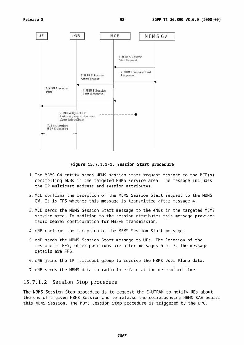
Figure 19.2.2.7.1b-1: MME initiated Reset procedure
- The MME triggers the RESET message to indicate that an initialisation in the eNB is required. The eNB releases the corresponding references and resources.
- Afterwards the eNB sends the RESET ACK message to confirm that the resources and references are cleared.
19.2.2.7.2 Error Indication functions and procedures
The Error Indication procedure is initiated by the eNB and the MME, to report detected errors in one incoming message, if an appropriate failure message cannot be reported to the sending entity.
19.2.2.7.2a eNB initiated error indication
Figure 19.2.2.7.2a-1: eNB initiated Error Indication procedure
- The eNB sends the ERROR INDICATION message to report the peer entity which kind of error occurs.
19.2.2.7.2b MME initiated error indication
Figure 19.2.2.7.2b-1: MME initiated Error Indication procedure
- The MME sends the ERROR INDICATION message to report the peer entity which kind of error occurs.
3GPP
3GPP TS 36.300 V8.6.0 (2008-09)98Release 8
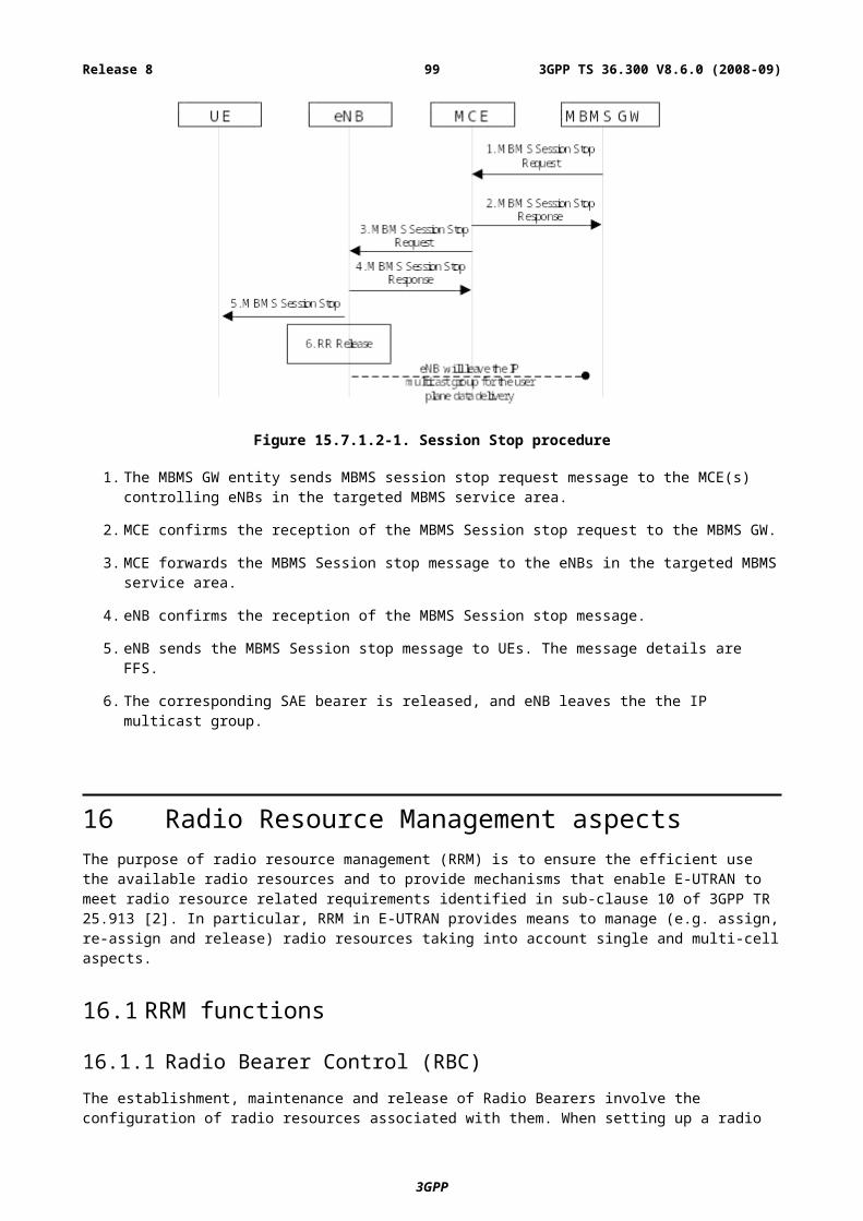
19.2.2.8 S1 Setup procedure
The S1 Setup procedure is used to exchange configured data which is required in the MME and in the eNB respectively to ensure a proper interoperation. The S1 Setup procedure is triggered by the eNB. The S1 Setup procedure is the first S1AP procedure which will be executed.
Figure 19.2.2.8-1: S1 Setup procedure
- The eNB initiates the S1 Setup procedure by sending the S1 SETUP REQUEST message including supported TAs and broadcasted PLMNs to the MME.
- In the successful case the MME responds with the S1 SETUP RESPONSE message which includes served PLMNs as well as a relative MME capacity indicator to achieve load balanced MMEs in the pool area.
- If the MME cannot accept the S1 Setup Request the MME responds with the S1 SETUP FAILURE message indicating the reason of the denial. The MME optionally indicates in the S1 SETUP FAILURE message when the eNB is allowed to re-initiate the S1 Setup Request procedure towards the same MME again.
19.2.2.9 eNB Configuration Update procedure
The eNB Configuration Update procedure is used to provide updated configured data in eNB. The eNB Configuration Update procedure is triggered by the eNB.
Figure 19.2.2.9-1: eNB Configuration Update procedure
- The eNB initiates the eNB Configuration Update procedure by sending the ENB CONFIGURATION UPDATE message including updated configured data like supported TAs and broadcasted PLMNs to the MME. In case one or more supported TA(s) needs to be updated, the eNB shall provide the whole list of TA(s), including those which has not been changed, in the ENB CONFIGURATION UPDATE message.
- The MME responds with the ENB CONFIGURATION UPDATE ACKNOWLEDGE message to acknowledge that the provided configuration data are successfully updated.
- The MME shall overwrite and store the received configuration data which are included in the ENB CONFIGURATION UPDATE message. Configuration data which has not been included in the ENB
3GPP
3GPP TS 36.300 V8.6.0 (2008-09)99Release 8
CONFIGURATION UPDATE message are interpreted by the MME as still valid. For the provided TA(s) the MME shall overwrite the whole list of supported TA(s).
- In case the MME cannot accept the received configuration updates the MME shall respond with the ENB CONFIGURATION UPDATE FAILURE message including an appropriate cause value to indicate the reason of the denial. The MME optionally indicates in the ENB CONFIGURATION UPDATE FAILURE message when the eNB is allowed to re-initiate the eNB Configuration Update procedure towards the same MME again. For the unsuccessful update case the eNB and the MME shall continue with the existing configuration data.
19.2.2.10 MME Configuration Update procedure
The MME Configuration Update procedure is used to provide updated configured data and changes of the relative MME capacity values in the MME. The MME Configuration Update procedure is triggered by the MME.
Figure 19.2.2.10-1: MME Configuration Update procedure
- The MME initiates the MME Configuration Update procedure by sending the MME CONFIGURATION UPDATE message including updated configured data like served PLMNs and changes of the relative MME capacity values to the eNB.
- The eNB responds with the MME CONFIGURATION UPDATE ACKNOWLEDGE message to acknowledge that the provided configuration data and the relative MME capacity values are successfully updated.
- The eNB shall overwrite and store the received configuration data and relative MME capacity values which are included in the MME CONFIGURATION UPDATE message. Configuration data which has not been included in the MME CONFIGURATION UPDATE message are interpreted by the eNB as still valid.
- In case the eNB cannot accept the received configuration updates the eNB shall respond with the MME CONFIGURATION UPDATE FAILURE message including an appropriate cause value to indicate the reason of the denial. The eNB optionally indicates in the MME CONFIGURATION UPDATE FAILURE message when the MME is allowed to re-initiate the MME Configuration Update procedure towards the same eNB again. For the unsuccessful update case the eNB and the MME shall continue with the existing configuration data and relative MME capacity values.
19.2.2.11 Location Reporting procedures
The Location Reporting procedures provide the means to report the current location of a specific UE.
The procedures providing this function are:
- Location Reporting Control procedure
- Location Report procedure
- Location Report Failure Indication procedure
3GPP
3GPP TS 36.300 V8.6.0 (2008-09)100Release 8
19.2.2.11.1 Location Reporting Control procedure
Figure 19.2.2.11.1-1: Location Reporting Control procedure
The Location Reporting Control procedure is initiated by the MME sending the LOCATION REPORTING CONTROL to the eNB to request the current location information, e.g. Cell ID, of a specific UE, and how the information shall be reported, e.g. direct report, report every cell change. The Location Reporting Control procedure is also used to terminate reporting on cell change.
If the Location Reporting Control procedure fails, e.g. due to an iteraction with an initiated hand over then the eNB shall indicate the failure using the Location Report Failure Indication procedure.
19.2.2.11.2 Location Report procedure
Figure 19.2.2.11.2-1: Location Report procedure
The Location Report procedure is initiated by the eNB by sending the LOCATION REPORT to the MME to report the current location information of a specific UE as a standalone report, or every time UE changes cell.
19.2.2.11.3 Location Report Failure Indication procedure
Figure 19.2.2.11.3-1: Location Report Failure Indication procedure
The Location Report Failure Indication procedure is initiated by the eNB by sending the LOCATION REPORT FAILURE INDICATION to the MME to indicate that the Location Report Control procedure has failed due to e.g. UE has performed inter-eNB handover.
3GPP
3GPP TS 36.300 V8.6.0 (2008-09)101Release 8
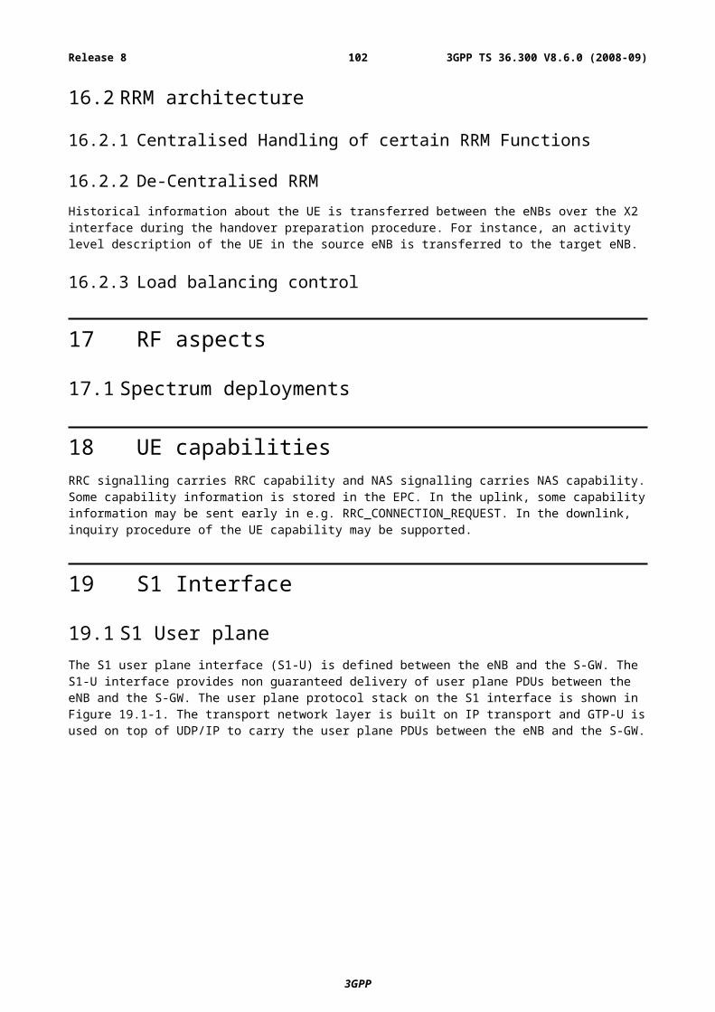
19.2.2.12 Overload procedure
19.2.2.12.1 Overload Start procedure
The Overload Start procedure is used by the MME to indicate to a proportion of eNBs to which the MME has an S1 interface connection that the MME is overloaded. The Overload Start procedure is used to provide an indication which signalling traffic needs to be rejected/permitted only.
Figure 19.2.2.12.1-1 Overload Start procedure
19.2.2.12.2 Overload Stop procedure
The Overload Stop procedure is used by the MME to indicate the concerned eNB(s) that the MME is no longer overloaded.
Figure 19.2.2.12.2-1: Overload Stop procedure
19.2.2.13 Write-Replace Warning procedure
Figure 19.2.2.13.1-1: Write-Replace Warning procedure
The Write-Replace Warning procedure is used to start the broadcasting and to overwrite the ongoing broadcasting of a warning message.
ETWS is an example of warning system using this procedure.
3GPP
3GPP TS 36.300 V8.6.0 (2008-09)102Release 8
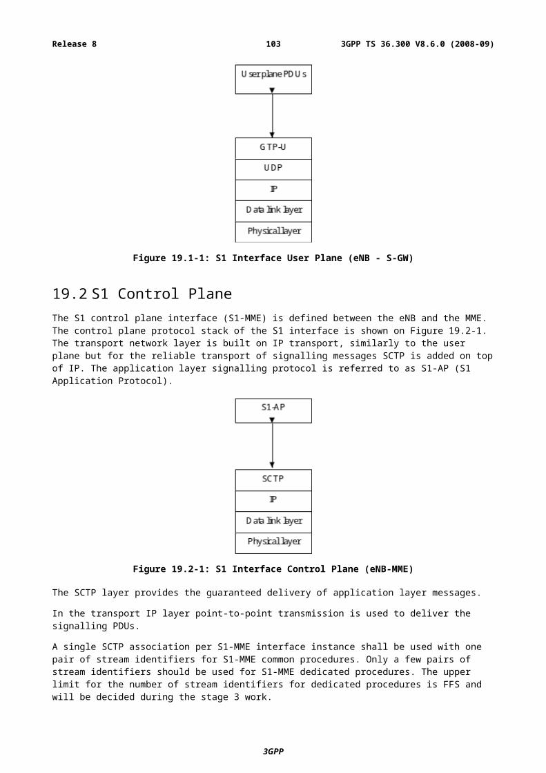
This procedure is initiated by the MME by sending WRITE-REPLACE WARNING REQUEST message containing at least the Message Identifier, Emergency Area list, information on how the broadcast should be performed, and the contents of the warning message to be broadcast.
The eNB responds with WRITE-REPLACE WARNING RESPONSE message to acknowledge that the requested ETWS message broadcast was initiated.
20 X2 Interface
20.1 User PlaneThe X2 user plane interface (X2-U) is defined between eNBs. The X2-U interface provides non guaranteed delivery of user plane PDUs. The user plane protocol stack on the X2 interface is shown in Figure 20.1-1. The transport network layer is built on IP transport and GTP-U is used on top of UDP/IP to carry the user plane PDUs.
The X2-UP interface protocol stack is identical to the S1-UP protocol stack.
Figure 20.1-1: X2 Interface User Plane (eNB-eNB)
20.2 Control PlaneThe X2 control plane interface (X2-CP) is defined between two neighbour eNBs. The control plane protocol stack of the X2 interface is shown on Figure 20.2-1 below. The transport network layer is built on SCTP on top of IP. The application layer signalling protocol is referred to as X2-AP (X2 Application Protocol).
3GPP
3GPP TS 36.300 V8.6.0 (2008-09)103Release 8
Figure 20.2-1: X2 Interface Control Plane
A single SCTP association per X2-C interface instance shall be used with one pair of stream identifiers for X2-C common procedures. Only a few pairs of stream identifiers should be used for X2-C dedicated procedures. The upper limit for the number of stream identifiers for dedicated procedures is FFS and will be decided during the stage 3 work.
Source-eNB communication context identifiers that are assigned by the source-eNB for X2-C dedicated procedures, and target-eNB communication context identifiers that are assigned by the target-eNB for X2-C dedicated procedures, shall be used to distinguish UE specific X2-C signalling transport bearers. The communication context identifiers are conveyed in the respective X2AP messages.
20.2.1 X2-CP FunctionsThe X2AP protocol supports the following functions:
- Intra LTE-Access-System Mobility Support for UE in ECM-CONNECTED:
- Context transfer from source eNB to target eNB;
- Control of user plane tunnels between source eNB and target eNB;
- Handover cancellation.
- Uplink Load Management;
- General X2 management and error handling functions:
- Error indication.
20.2.2 X2-CP ProceduresThe elementary procedures supported by the X2AP protocol are listed in Table 20.2.2-1 below:
3GPP
3GPP TS 36.300 V8.6.0 (2008-09)104Release 8
Table 20.2.2-1: X2-CP Procedures
Elementary Procedure
Initiating Message
Response Message of Successful Outcome
Response Message of Unsuccessful Outcome Description & comments
Handover Preparation
HANDOVER REQUEST
HANDOVER REQUEST
ACKNOWLEDGE
HANDOVER PREPARATION
FAILURE
Used by source eNB to request a handover to the target eNB
Handover Cancellation
HANDOVER CANCEL
Used by the source eNB to cancel a previously requested handover in a target eNB
UE Context Release
UE CONTEXT RELEASE
- - Used by the target eNB to signal to source eNB that control plane resources for the handed over UE context can be released.
Error Indication
ERROR INDICATION
- - Used by the eNB to report errors in a received message provided they cannot be reported by an appropriate response message.
Load Management
LOAD INDICATOR
- - Used by the eNB to report its load conditions to its neighbour eNBs.
Note: this initial list might be extended.
20.2.2.1 Handover Preparation procedure
The Handover preparation procedure is initiated by the source eNB if it determines the necessity to initiate the handover via the X2 interface.
Figure 20.2.2.1-1: Handover Preparation procedure
The source eNB sends a HANDOVER REQUEST to the target eNB including the bearers to be setup by the target ENB.
The handover preparation phase is finished upon the reception of the HANDOVER REQUEST ACKNOWLEDGE in the source eNB, which includes at least radio interface related information (HO Command for the UE), successfully established EPS Bearer(s) and failed established EPS Bearer(s).
In case the handover resource allocation is not successful (e.g. no resources are available on the target side) the target eNB responds with the HANDOVER PREPARATION FAILURE message instead of the HANDOVER REQUEST ACKNOWLEDGE message.
If eNB received NAS message from MME during X2 handover procedure, it shall be acted as specified in subclause 19.2.2.6.
3GPP
RRC: HANDOVER COMMAND X2-AP: HANDOVER REQUEST ACKNOWLEDGE
Source eNB Target eNBUE
X2-AP: HANDOVER PREPARATION FAILURE
X2-AP: HANDOVER REQUEST
3GPP TS 36.300 V8.6.0 (2008-09)105Release 8
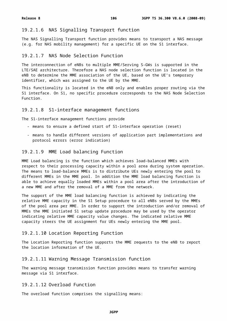
20.2.2.2 Handover Cancellation procedure
This functionality is located in the source eNB to allow cancellation of the handover procedure.
Figure 20.2.2.2-1: Handover Cancellation procedure
The source eNB sends a HANDOVER CANCEL message to the target eNB indicating the reason for the handover cancellation.
20.2.3 Inter-cell Load ManagementInter-cell load management in E-UTRAN is performed through the X2 interface. In case of variation in the load condition, the eNodeB signals the new load condition to its neighbour eNodeBs e.g. the neighbour eNodeBs for which an X2 interface is configured due to mobility reasons.
The LOAD INDICATOR message is used to signal the load conditions between eNodeBs.
Figure 20.2.3-1: LOAD INDICATOR message over X2
3GPP
Source eNB Target eNBUE
X2-AP: HANDOVER CANCEL
3GPP TS 36.300 V8.6.0 (2008-09)106Release 8
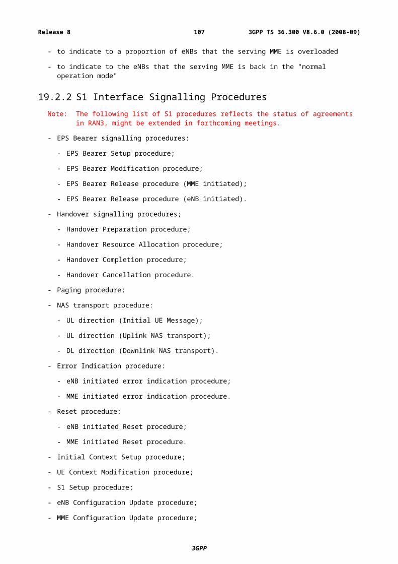
21 System and Terminal complexity
21.1 Overall System complexity
21.2 Physical layer complexity
21.3 UE complexity
22 Support for self-configuration and self-optimisation
22.1 DefinitionsThis concept includes several different functions from eNB activation to radio parameter tuning. Figure 22.1-1 is a basic framework for all self-configuration /self-optimization functions.
Self-configuration process is defined as the process where newly deployed nodes are configured by automatic installation procedures to get the necessary basic configuration for system operation.
This process works in pre-operational state. Pre-operational state is understood as the state from when the eNB is powered up and has backbone connectivity until the RF transmitter is switched on.
As described in Figure 21.1, functions handled in the pre-operational state like:
- Basic Setup and
- Initial Radio Configuration
are covered by the Self Configuration process.
NOTE: depending on the final chosen functional distribution in RAN, the feasibility of following items should be studied e.g.:
- To obtain the necessary interface configuration;
- Automatic registration of nodes in the system can be provided by the network;
- Alternative possibilities for nodes to obtain a valid configuration;
- The required standardization scope.
Self-optimization process is defined as the process where UE & eNB measurements and performance measurements are used to auto-tune the network.
This process works in operational state. Operational state is understood as the state where the RF interface is additionally switched on.
As described in Figure 21.1, functions handled in the operational state like:
- Optimization / Adaptation
are covered by the Self Optimization process.
NOTE: depending on the final chosen functional distribution in RAN the feasibility of following items should be studied e.g.:
- The distribution of data and measurements over interfaces relevant to RAN3;
- Functions/entities/nodes in charge of data aggregation for optimization purpose;
3GPP
3GPP TS 36.300 V8.6.0 (2008-09)107Release 8
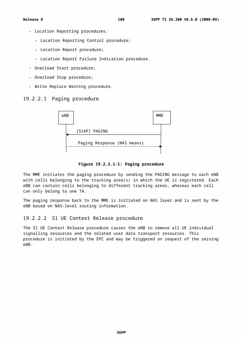
- Dependencies with O&M and O&M interfaces, in the self optimization process;
- The required standardization scope.
The architecture of logical self-configuration/optimization functionality is FFS.
Figure 22.1-1: Ramifications of Self-Configuration /Self-Optimization functionality
22.2 UE Support for self-configuration and self-optimisationUE shall support measurements and procedures which can be used for self-configuration and self-optimisation of the E-UTRAN system.
- UE shall support measurements and measurement reporting to support self-optimisation of the E-UTRAN system. Measurements and reports used for the normal system operation, should be used as input for the self-optimisation process as far as possible.
NOTE: the UE impact should be carefully investigated and taken into account.
- The network is able to configure the measurements and the reporting for self-optimisation support by RRC signalling messages.
- It shall be possible to associate measurements for self-optimisation purpose with location information depending on UE capability (details are [FFS]).
22.3 Self-configuration
22.3.1 Dynamic configuration of the S1-MME interface
22.3.1.1 Prerequisites
The following prerequisites are assumed:
3GPP
3GPP TS 36.300 V8.6.0 (2008-09)108Release 8
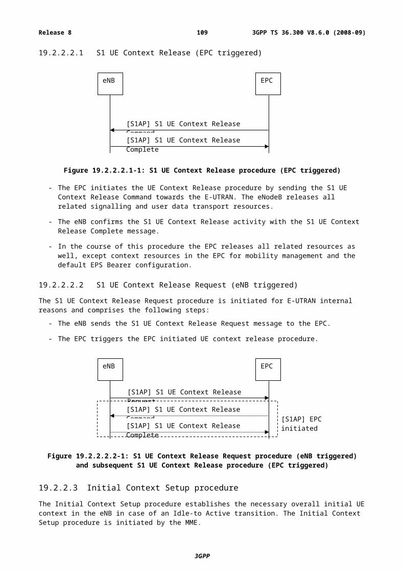
- An initial remote IP end point to be used for SCTP initialisation is provided to the eNB for each MME in the pre operational state.
How the eNB gets the remote IP end point(s) and its own IP address are FFS.
- Other relevant information from/to eNB to/from MME to self-configure S1-MME are FFS
22.3.1.2 SCTP initialization
- For each MME the eNodeB tries to initialize a SCTP association as described in RFC2960 [8], using a known initial remote IP Endpoint as the starting point, until SCTP connectivity is established.
22.3.1.3 Application layer initialization
Once SCTP connectivity has been established, the eNodeB and MME shall exchange application level configuration data over the S1-MME application protocol with the S1 Setup Procedure, which is needed for these two nodes to interwork correctly on the S1 interface. The details of the information exchange outlined below are FFS, and dependent on the further standardization of the S1 interface.
- The eNodeB provides the relevant information to the MME , which may include node ID, list of supported TA(s), etc. Details of the relevant information needed to setup the S1-MME interface is subject to stage3 discussion and is left FFS.
- The MME provides the relevant information to the eNodeB, which may include node ID, PLMN ID, etc. Details of the relevant information needed to setup the S1-MME interface is subject to stage3 discussion and is left FFS.
- When the application layer initialization is successfully concluded, and has been mutually acknowledged by the two peer nodes, the dynamic configuration procedure is completed, and the S1-MME interface is operational.
22.3.2 Dynamic Configuration of the X2 interfaceEditors Note: The Dynamic configuration of the X2 interface is expected to work in a similar manner as the
Dynamic Configuration of the S1-MME interface (section 22.3.1).
22.3.2.1 Prerequisites
22.3.2.2 SCTP initialization
22.3.2.3 Application layer initialization
22.3.3 Intra-LTE/frequency Automatic Neighbour Relation FunctionThe ANR (Automatic Neighbor Relation) function relies on cells broadcasting their identity on global level, Cell Global-Cell-Identifier (Global-CID).
3GPP
3GPP TS 36.300 V8.6.0 (2008-09)109Release 8
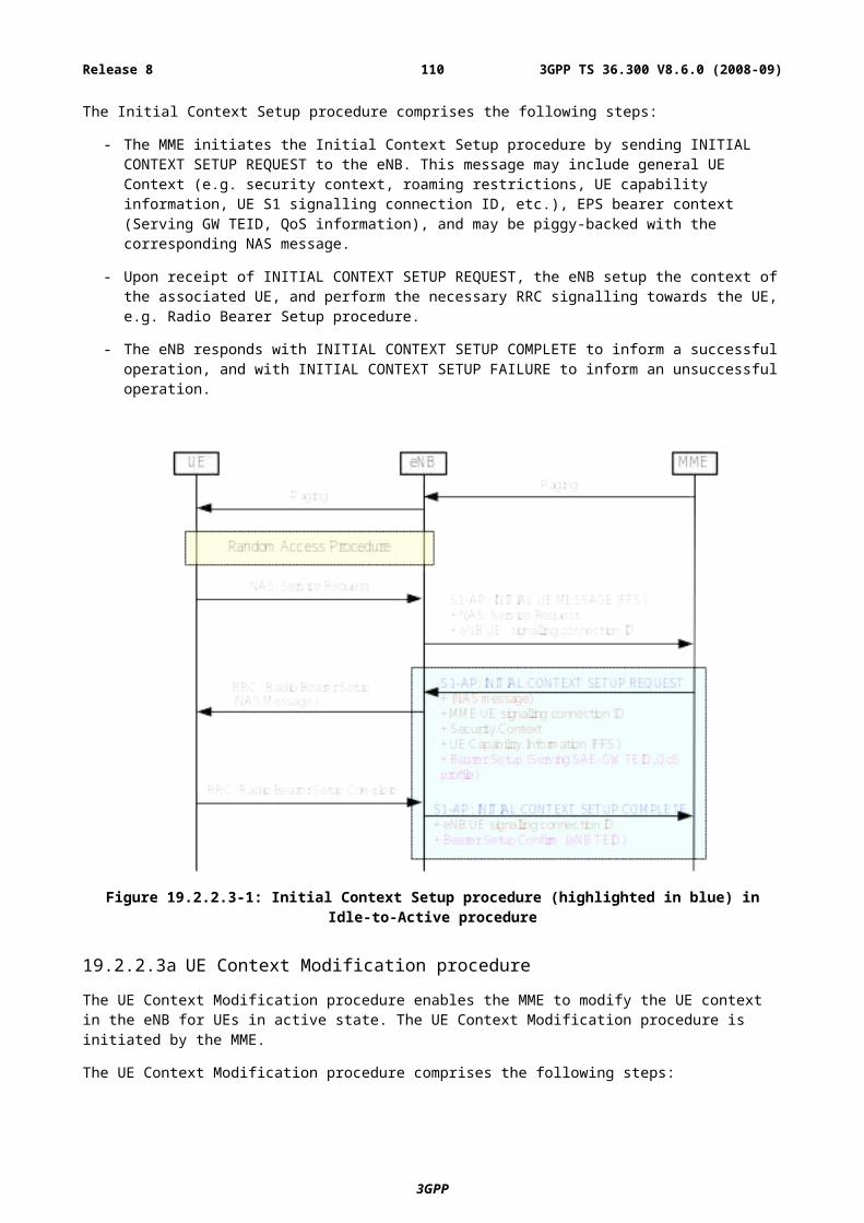
Figure 22.3.3-1: Automatic Neighbor Relation Function
It is assumed that this function executes under the constraints of the O&M system which can manage:
ANR Blacklist: List of cells to which the eNodeB shall neither establish nor keep a neighbour relation.
ANR Whitelist: List of cells to which the eNodeB shall always establish and maintain a neighbour relation.
It is also assumed that the O&M system is informed about changes in the eNodeB neighbour relation list.
The function works as follows:
The eNodeB serving cell A has an ANR function. As a part of the normal call procedure, the eNodeB instructs each UEs to perform measurements on neighbor cells. The eNodeB may use different policies for instructing the UE to do measurements, and when to report them to the eNodeB. This measurement procedure is as specified in TS36.331.
1. The UE sends a measurement report regarding cell B. This report contains Cell B’s Phy-CID, but not its Global-CID.
When the eNodeB receives a UE measurement report containing Phy-CID, the following sequence may be used.
2. The eNodeB instructs the UE, using the newly discovered Phy-CID as parameter, to read the Global-CID, TAC and all available PLMN ID(s) of the related neighbor cell. To do so, the eNodeB may need to schedule appropriate idle periods to allow the UE to read the Global-CID from the broadcast channel of the detected neighbour cell. It is FFS how the UE reads the Global-CID.
3. When the UE has found out the new cell’s Global-CID, the UE reports the detected Global-CID to the serving cell eNodeB. In addition the UE reports the tracking area code and all PLMN IDs that have been detected, whenever eNB requests this information.
4. The eNodeB decides to add this neighbor relation, and can use Phy-CID and Global-CID to:
a Lookup a transport layer address to the new eNodeB (FFS if this needs to be standardized by 3GPP).
b Update its Neighbor Relation List.
c If needed, setup a new X2 interface towards this eNodeB. The setup of the X2 interface is described in section 22.3.2.
The exchange of further information for ANR optimisation purposes is FFS.
3GPP
3GPP TS 36.300 V8.6.0 (2008-09)110Release 8
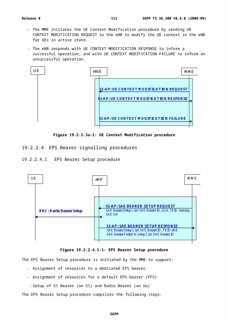
22.3.4 Inter-RAT/Inter-frequency Automatic Neighbour Relation Function
Figure 22.3.4-1: Automatic Neighbor Relation Function in case of UTRAN detected cell
It is assumed that this function executes under the constraints of the O&M system which can manage:
Inter-RAT/inter-frequency Searchlist: List of RATs/Frequencies that shall be searched.
Inter-RAT/inter-frequency ANR Blacklist: List of inter-RAT/inter-frequency cell to which the eNodeB shall neither keep nor establish a neighbour relation.
Inter-RAT/inter-frequency ANR Whitelist: List of inter-RAT/inter-frequency cells to which the eNodeB shall always establish and maintain a neighbour relation.
It is also assumed that the O&M system is informed about changes in the eNodeB inter-RAT/inter-frequency neighbour lists.
The function works as follows:
The eNodeB serving cell A has an ANR function. During connected mode, the eNodeB can instruct a UE to perform measurements and detect cells on other RATs/frequencies. The eNodeB may use different policies for instructing the UE to do measurements, and when to report them to the eNodeB.
1 The eNodeB instructs a UE to look for neighbour cells in the target RATs/frequencies. To do so the eNodeB may need to schedule appropriate idle periods to allow the UE to scan all cells in the target RATs/frequencies.
2 The UE reports the Phy-CID of the detected cells in the target RATs/frequencies. The Phy-CID is defined by the carrier frequency and the Primary Scrambling Code (PSC) in case of UTRAN FDD cell, by the carrier frequency and the cell parameter ID in case of UTRAN TDD cell and by the Band Indicator + BSIC + BCCH ARFCN in case of GERAN cell.
When the eNodeB receives UE reports containing Phy-CIDs of cell(s) the following sequence may be used.
3GPP
3GPP TS 36.300 V8.6.0 (2008-09)111Release 8
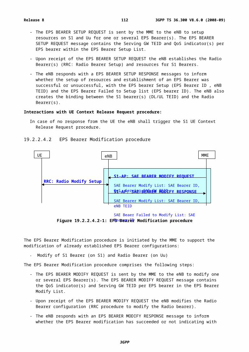
3 The eNodeB instructs the UE, using the newly discovered Phy-CID as parameter, to read the Global-CID and the RAC of the detected neighbour cell in case of GERAN detected cells and Global-CID, LAC and, RAC in case of UTRAN detected cells. For the Interfrequency case, the eNodeB instructs the UE, using the newly discovered Phy-CID as parameter, to read the Global-CID, TAC and all available PLMN ID(s) of the inter-frequency detected cell. It is FFS how this is achieved. The UE ignores transmissions from the serving cell while finding the requested information transmitted in the broadcast channel of the detected inter-system/inter-frequency neighbour cell. To do so, the eNodeB may need to schedule appropriate idle periods to allow the UE to read the requested information from the broadcast channel of the detected inter-system/inter-frequency neighbour cell.
4 After the UE has read the requested information in the new cell, it reports the detected Global-CID and RAC (in case of GERAN detected cells) or Global-CID, LAC and RAC (in case of UTRAN detected cells) to the serving cell eNodeB. In the inter-frequency case, the UE reports the Globall-CID, the, tracking area code and all PLMN-ID(s) that have been detected.
5 The eNodeB updates its inter-RAT/inter-frequency neighbour relation lists.
In the inter-frequency case and if needed, the eNodeB can use Phy-CID and Global-CID at a new X2 interface setup towards this eNodeB. The setup of the X2 interface is described in section 22.3.2.
23 Others
23.1 Support for real time IMS services
23.2 Subscriber and equipment trace Support for subscriber and equipment trace for LTE and SAE shall be as specified in 3GPP specifications 32.421, 32. 422, 32.423 and 3GPP Trace IRP 32.441, 32.442 and 32.443.
All traces are initiated by the core network, even if the trace shall be carried out in the radio network.
The following functionality is needed on the S1 and X2 interface:
- Support for inclusion of subscriber and equipment trace information in INITIAL CONTEXT SETUP REQUEST message over the S1 interface.
- Support for an explicit TRACE START message over the S1 interface.
- Support for inclusion of subscriber and equipment trace information in the HANDOVER REQUEST message over the X2 interface.
- Support for inclusion of subscriber and equipment trace information in the HANDOVER REQUEST message over the S1 interface.
A trace setup in the radio network will be propagated on the X2 interface at handover and on the S1 interface if the handover is carried out between MMEs.
3GPP
3GPP TS 36.300 V8.6.0 (2008-09)112Release 8
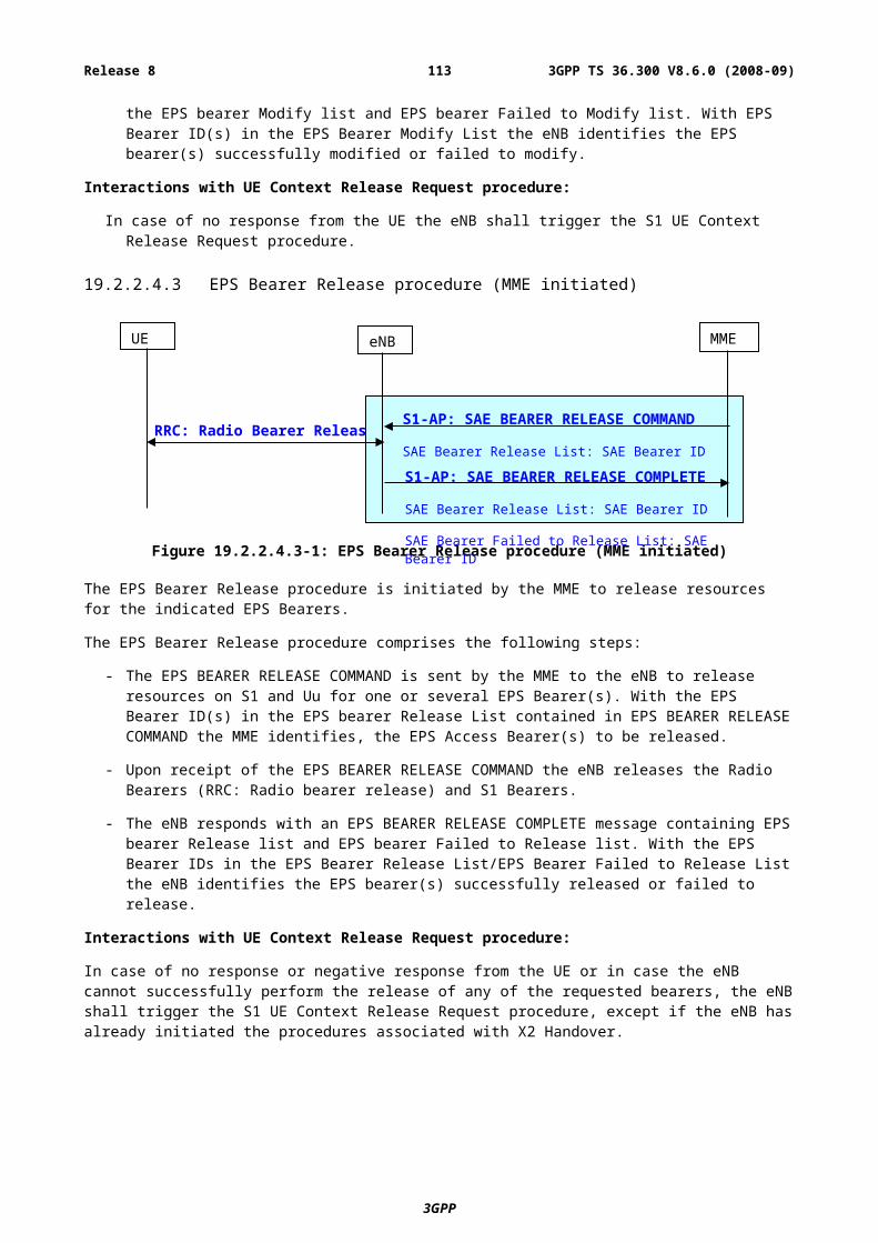
Annex A (informative):NAS OverviewThis subclause provides for information an overview on services and functions provided by the NAS control protocol..
A.1 Services and FunctionsThe main services and functions of the NAS sublayer include:
- EPS Bearer control (see 3GPP TR 23.401 [17]);
- ECM-IDLE mobility handling;
- Paging origination;
- Configuration and control of Security.
A.2 NAS protocol states & state transitionsThe NAS state model is based on a two-dimensional model which consists of EPS Mobility Management (EMM) states describing the mobility management states that result from the mobility management procedures e.g. Attach and Tracking Area Update procedures, and of EPS Connection Management (ECM) states describing the signalling connectivity between the UE and the EPC (see 3GPP TS 23.401 [17]).
NOTE: The ECM and EMM states are independent of each other and when the UE is in EMM-CONNECTED state this does not imply that the user plane (radio and S1 bearers) is established.
The relation between NAS and AS states is characterised by the following principles:
- EMM-DEREGISTERED & ECM-IDLE RRC_IDLE:
- Mobility: PLMN selection:
- UE Position: not known by the network.
- EMM-REGISTERED & ECM-IDLE RRC_IDLE:
- Mobility: cell reselection;
- UE Position: known by the network at tracking area level.
- EMM-REGISTERED & ECM-CONNECTED with radio bearers established RRC_CONNECTED.
- Mobility: handover;
- UE Position: known by the network at cell level.
3GPP
3GPP TS 36.300 V8.6.0 (2008-09)113Release 8
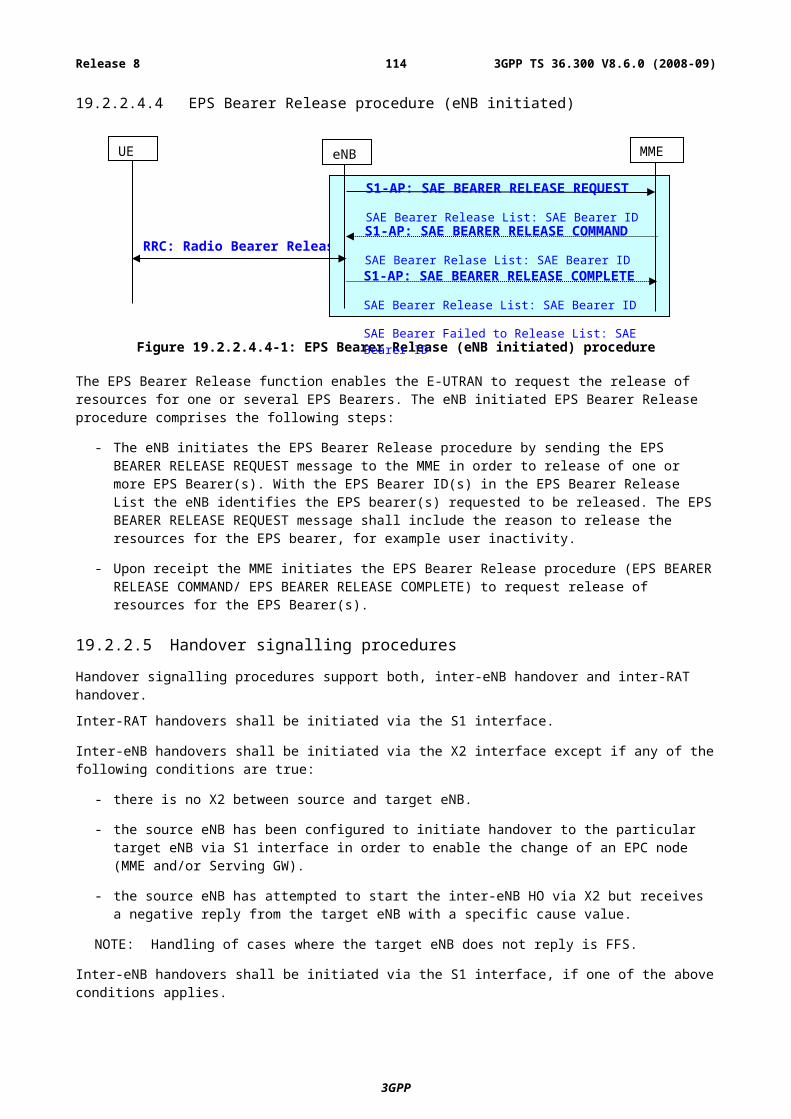
Annex B (informative):MAC and RRC ControlThe E-UTRA supports control signalling in terms of MAC control signalling (PDCCH and MAC control PDU) and RRC control signalling (RRC message).
B.1 Difference between MAC and RRC controlThe different characteristics of MAC and RRC control are summarized in the table below.
Table B.1-1: Summary of the difference between MAC and RRC control
MAC control RRC control
Control entity MAC RRC
Signalling PDCCH MAC control PDU RRC message
Signalling reliability ~ 10-2 (no retransmission) ~ 10-3 (after HARQ) ~ 10-6 (after ARQ)
Control delay Very short Short Longer
Extensibility None or very limited Limited High
Security No integrity protection No ciphering
No integrity protectionNo ciphering
Integrity protected Ciphering (FFS)
The main difference between MAC and RRC control lies in the signalling reliability. Due to the signalling reliability, signalling involving state transitions and radio bearer configurations should be performed by RRC. Basically, all signalling performed by RRC in UTRA should also be performed by RRC also for E-UTRA.
B.2 Classification of MAC and RRC control functionsThe table below illustrates the classification of MAC and RRC control functions for E-UTRAN.
Table B.2-1: Classification of MAC and RRC control functions
Controlled configuration/parameters
MAC control
signalling
PDCCH Short-lived (PRB) and dynamic (MCS) allocationLong-lived (PRB) and fixed (MCS) allocation (FFS)Timing Advance (FFS)
MAC control PDU
Timing Advance (FFS)RLC related control PDU (FFS)
RRC control signalling
RRC message
Long-lived (PRB) and fixed (MCS) allocation (FFS)Activation/deactivation of long-lived (PRB) and/or fixed (MCS) allocation (FFS)TTI configuration for variable TTI length control (FFS)Static parameter configuration for UE inactivity control within RRC_ACTIVE (e.g. DRX/DTX periods)
3GPP
3GPP TS 36.300 V8.6.0 (2008-09)114Release 8
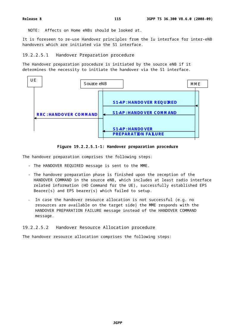
Annex C (informative):System InformationThis annex provides an overview of the classification and division of system information between static and flexible parts. Considerations about dedicated distribution of system information are also included.
C.1 SI classificationFive categories are identified for system information classification:
1. Information valid across multiple cells;
2. Information needed at cell/PLMN search;
3. Information needed prior to cell camping;
4. Information needed before cell access;
5. Information needed while camping on a cell.
From UEs’ point of view, the information that is needed at cell selection and prior to camping are very similar. Before a UE can camp on a cell, it needs to know if the access is allowed in that cell. Thus it would be very beneficial to know all access restrictions already at cell search phase.
C.1.1 Information valid across multiple cellsThe pieces of information that can be valid across multiple cells are:
- A-GNSS assistance data;
- PLMN identity(ies);
- Tracking area identity;
Note: the above text will be revised if it is agreed that a cell can be a member of more than one tracking area.
- Predefined configuration information;
- System Frame Number if it does not change from cell to cell (in case of synchronized network);
- Some measurement/mobility information (FFS).
C.1.2 Information needed at cell/PLMN searchIn order to support full mobility within the serving frequency layer, the UEs need to perform cell search rather often and thus it is seen very important that the information needed in cell search phase is readily available, thereby improving cell search times and minimizing UE power consumption. If system information decoding is needed for identifying a cell, fast system information reception is needed in order to avoid too long identification times. For optimising PLMN search and make PLMN search fast and non-complex, the information needed for PLMN search should be easily available. The pieces of information that are needed at cell/PLMN search are:
- PLMN identity(ies): in order to acquire information to which PLMN the cell belongs, UEs need to receive PLMN identity(ies);
NOTE: There may be multiple PLMN identities for one cell.
- Measurement cell identity (FFS): there needs to be a cell identity in the system information, in order to allow UEs to identify the cell reliably for measurement purposes.
3GPP
3GPP TS 36.300 V8.6.0 (2008-09)115Release 8
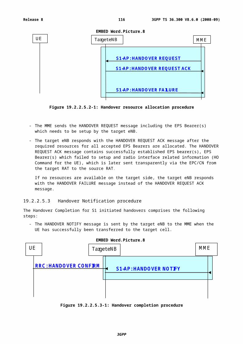
NOTE: UEs may identify the cell also based on the reference sequence detection;There is another cell identity that identifies the cell within e.g. PLMN.
NOTE: UEs may have to check possible cell access restrictions before selecting cell/PLMN;For cell/PLMN search UEs might need some L1 parameters.
C.1.3 Information needed prior to cell campingBefore a UE can camp on a cell, it needs to know any access related parameters in order to avoid camping on cells where access is forbidden. Thus prior to camping on a cell, a UE needs to know the following information:
- Any cell access restriction parameters, e.g.:
- Tracking area identity: if the forbidden TA concept is adopted from legacy systems, then the UE needs to know whether the cell belongs to such forbidden TA.
Note: the above text will be revised if it is agreed that a cell can be a member of more than one tracking area.
- Cell barring status and cell reservation status (FFS if needed per PLMN): the UE needs to know whether the cell is barred or reserved in order to avoid camping on a barred cell. Possibly also barring time might be needed in order to avoid UE to poll barring time frequently from the system information. Another option is that barring status is indicated also in the neighbour cell list.
- Radio access limitation parameters:
- Any radio condition parameters that limit the access to the cell e.g. similar to GSM C1/S criteria;
- It is FFS if we need to have some band information indication also, in order to allow UEs to check possible band support before camping on the cell.
NOTE: UE may need some L1 parameters prior to camping.
C.1.4 Information needed prior to cell accessOnce a UE has camped on a cell, the information needed prior to cell access (transmission/reception) includes at least:
- System Frame Number (SFN) (FFS)
- SFN is probably needed by the UE to understand the scheduling parameters (e.g. scheduling information for secondary SI, RACH, PCH, E-MBMS etc.)
- L1 information, example set of needed L1 parameters:
Note: RAN1 needs to define what parameters are needed at this phase.
- Carrier Bandwidth: FFS if separate bandwidths for UL and DL are needed;
- Carrier center frequency (FFS);
- Cyclic Prefix parameters: in order to decode DL-SCH UE needs to know the CP length arrangements;
- MIMO related parameters: in order to take advantage of the multi-antenna transmissions like MIMO, the UE needs to know parameters of number of TX antennas, DL/UL pre-coding matrices, etc...;
- Band Information: may be needed if the same DL carrier frequency has variable UL carrier frequency;
- PDCCH, PHICH and PUCCH structure parameters: if PDCCH has variable configurations, the UE may need to know its channel structure at least partly. PDCCH is crucial to receive any allocation information. If Random Access Response is transmitted without PDCCH (e.g. synchronous transmission with Random Access Preamble), this information might not be required;
- RACH parameters (needed by the UE to start usage of RACH):
3GPP
3GPP TS 36.300 V8.6.0 (2008-09)116Release 8
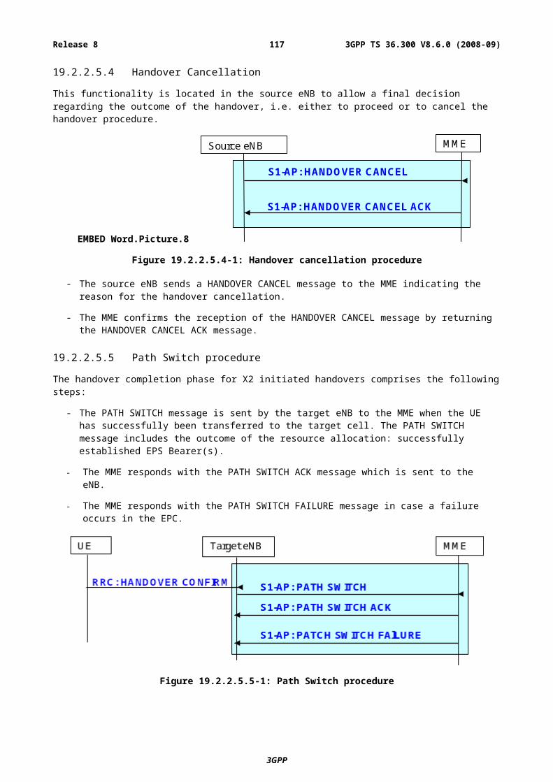
- RACH scheduling information: UE needs to know where in time (sub-frame) and frequency (Physical Resource Units) the RACH channel is located;
- RACH sequences: UE needs to know the RACH set of sequences to choose from. The sequences may not be fully of equal meaning (e.g. CQI can be classified for the sequences in a specific way);
- Access class restrictions: access class restrictions might be needed to limit the number of possible UEs using RACH;
- Persistence values: possible persistence value scheme parameters are needed for RACH usage;
- Other parameters related to RACH: UE needs to know the timers and parameters related to RACH e.g. how often the UE retransmits RACH and how many times the retransmission is allowed etc;
- RACH power control parameters: UE needs to know parameters related to UL power control.
C.1.5 Information needed while camping on a cellWhen a UE has camped on a cell, it needs to continue measuring the neighbouring cells in order to stay camped. The pieces of information required for that are:
- Measurement parameters:
- In order for the UE to start mobility procedures, it needs to receive parameters e.g. of reporting periods, reporting event parameters, time to trigger etc. UEs in RRC_IDLE state need cell reselection parameters. UEs in RRC_CONNECTED state need parameters of the neighbour cells e.g. for handover and for error recovery cases.
- Neighbour cell lists are needed to start neighbour cell measurements. UEs in different states may use different sets of neighbour cell lists. Neighbour cell list may contain following parameters:
- Some L1 parameters: FFS what parameters are needed in the neighbour cell list;
- All information that is needed for camping: see sub-clauses C.2.2 and C.2.3 (FFS);
- Synchronization information: indicating whether the neighbouring cell is synchronized to the current cell i.e. the cell sending the neighbour cell list (FFS);
- PLMN identity(ies) & tracking area identity (FFS);
Note: The above text will be revised if it is agreed that a cell can be a member of more than one tracking area.
- Other 3GPP RAT information: e.g. neighbour cell information of GERAN/UTRAN cells;
- Information of non-3GPP access systems (e.g. WIMAX).
- Secondary NAS parameters:
- An y NAS parameters that were not presented earlier e.g. cell identity uniquely identifying cell within wide area e.g. PLMN;
- Cell identity (PLMN level) (FFS if this should be in category “Information needed prior to cell access”).
- Secondary UE timer values: any timer values that affect UE’s behaviour.
- Paging parameters: UEs in ECM-IDLE state need to receive paging parameters e.g. DRX periods and scheduling.
- Clock time (FFS): the network might send system clock in order to let UEs update their clock time e.g. in the user interface;
- MBMS service parameters: any parameters needed for MBMS reception e.g. MBMS multiplexing parameters, MBMS frequency;
NOTE: the presence of these parameters also indicate the presence of MBMS service in the cell (dedicated or mixed cell).
3GPP
3GPP TS 36.300 V8.6.0 (2008-09)117Release 8
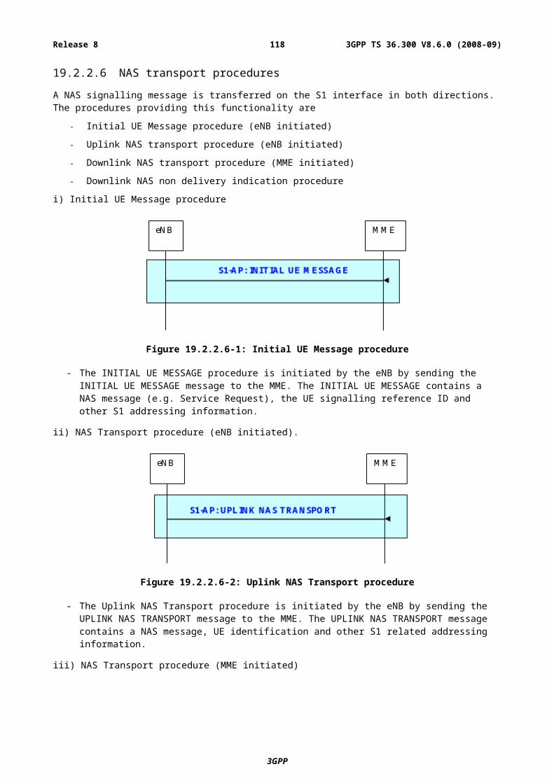
- Signalling Radio Bearer parameters: may be broadcasted unless they are standardized.
C.1.6 Thoughts about category divisionFrom UEs’ point of view the categories in sub-clauses C.1.2 and C.1.3 are very similar. Thus it is questionable whether we need to differentiate procedures between cell search/selection/camping and PLMN search.
From UEs’ point of view, the difference between the procedure for cell search during RRC_CONNECTED and the procedure for cell search during RRC_IDLE state maybe small. When the UE is in RRC_CONNECTED state, it measures the neighbour cell and executes handovers commanded by the network.
C.2 Division of SI between static and flexible partsSystem information distribution can be classified into two distinctive parts: static and flexible. Static part is sent more often, say once per frame, in the cell and has quite a limited capacity for information transfer. The flexible part has flexible amount of scheduled resources available and thus most of the SI information is contained there.
C.2.1 Static partThe static parts of the System Information are:
- L1 information in order to decode the rest of the information
Note: detailed information on the required information will be defined by RAN1;
- Measurement Cell identity (FFS): it may be possible that L1 channels do not identify the cell. Then some Cell identity needs to be sent on system information part;
- Any cell access restriction parameters e.g.:
- Tracking area identity: if forbidden TA concept is adopted from legacy systems then UEs need to know whether the cell belongs to forbidden TA;
Note: the above text will be revised if it is agreed that a cell can be a member of more than one tracking area.
- Cell barring and cell reservation status (FFS if needed per PLMN): UEs need to know whether cell is barred or reserved in order to avoid camping on barred cell. Possibly also barring time might be needed in order to avoid UEs to poll barring time frequently from the system information;
- Radio access limitation parameters: any radio condition parameters that limit the access to the cell e.g. similar to GSM C1/S criteria;
- PLMN identity(ies): in order to acquire information to which PLMN cell belongs, UEs need to receive PLMN identity(ies).
NOTE: there may be multiple PLMN identities for one cell.
- Scheduling parameters:
- All of the scheduling information of flexible part or part of scheduling information (e.g. scheduling block) of flexible part. If static part consists of multiple SI blocks then it may be necessary to have scheduling information of those blocks in the static part.
- Scheduling block defines, from where (time and frequency resources) to decode the SI blocks of the scheduled flexible part. It may be possible that scheduling of scheduling block is standardized, then this information can be omitted from the static part. If several types of scheduling blocks are defined , scheduling information might be sent for each scheduling block.
- Value_tag(s): informs whether the information transmitted on the flexible part has changed. This is needed in order to avoid UEs from reading any unchanged information repeatedly. Another possibility is to send this information in PDCCH, but possibly it would cause too much overhead.
3GPP
3GPP TS 36.300 V8.6.0 (2008-09)118Release 8
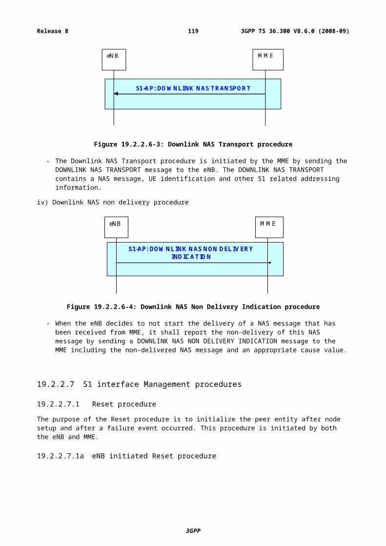
NOTE: It also is possible to include Value_tag for SI on the flexible part indicating more precisely what changes have occurred in the system information.
NOTE: There may be a need for indicating changes in static part with value tag also, if static part consists of multiple SI blocks.
Table C.2.1-1 gives an estimate of the size of the elements mentioned above.
Table C.2.1-1: Initial rough estimates for static part capacity requirement
Information element BitsCyclic Prefix (FFS) 2Carrier BW (FFS) 3-8
MIMO parameters (FFS) 2 (+ 3)Cell Id (FFS) 9
Tracking Area Id (+ FFS how many additional) [16-28]Cell Barring status+ possible Time of barring 1+4
Cell reservation status [2]Radio access limitation parameters 12
PLMN id(s) maximum of 5 ( 24 bits per one) - see Note 120Scheduling parameters (12-108)
Value Tag 4SFN (FFS) 11
NOTE: It might not be necessary to send the Mobile Country Code part of the PLMN identity for each indicated PLMN to limit the number of bits.
C.2.2 Flexible partThe flexible part has different types of Information Elements which require independent scheduling in order to allow fast enough reception and not to waste transmission capacity. For example, the requirement to receive cell access parameters is very different than e.g. the clock time. Thus following flexible part division should be considered:
- Scheduling block: scheduling information of the secondary part of the System Information.
- Access parameters:
- All parameters not present in the primary part (e.g. some L1 parameters);
- RACH parameters;
- Power control parameters;
- Paging parameters;
- Any timer values needed for operating in the cell and in the network.
- Measurement related parameters:
- Neighbour cell lists;
- Cell selection/reselection parameters;
NOTE: Some of these parameters are included in the static part element “Radio access limitation parameters.”
- Measurement control information;
- Non vital information:
- Clock time;
- Positioning (A-GNSS etc.) information;
3GPP
3GPP TS 36.300 V8.6.0 (2008-09)119Release 8
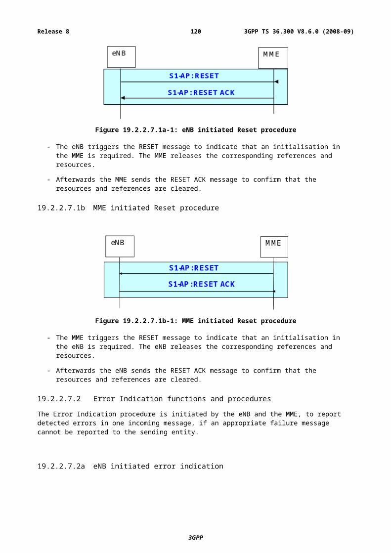
- Service parameters (e.g. MBMS parameters);
- Secondary NAS parameters.
C.2.3 Information whose location is FFSThe location of the following information is FFS:
- System Frame Number: SFN might be needed very fast i.e. for HO purposes. SFN might be needed also for decoding scheduling block parameters, but on the other hand it might be requested not to send often changing information on the static part in order to be able to make time soft combining. Further investigation on the SFN broadcasting is thus needed.
C.2.4 Dedicated partThe dedicated part is embedded in the RRC message that is meant for sending System Information Elements in unicast mode e.g. for HO purposes, positioning purposes …. The UE needs some information for the neighbouring cell to access it, this is needed to limit the interruption times caused by HO execution. When a UE receives a HO COMMAND it needs at least following information from the target cell:
- All information in the static part (see sub-clause C.2.1): may be received by the UE by itself;
- Most of the information from the access parameters (see sub-clause C.2.2): is favourably delivered by dedicated manner via the source cell, because the UE might not have time to get all the necessary secondary SI from the target cell;
- System Frame Number is needed to minimize the interruption times during the HO procedure. Most probably the UE needs to receive (at least confirm) the SFN directly by the neighbour cell SI reading, because giving the SFN via source cell may cause some inaccuracy to the SFN.
3GPP
3GPP TS 36.300 V8.6.0 (2008-09)120Release 8
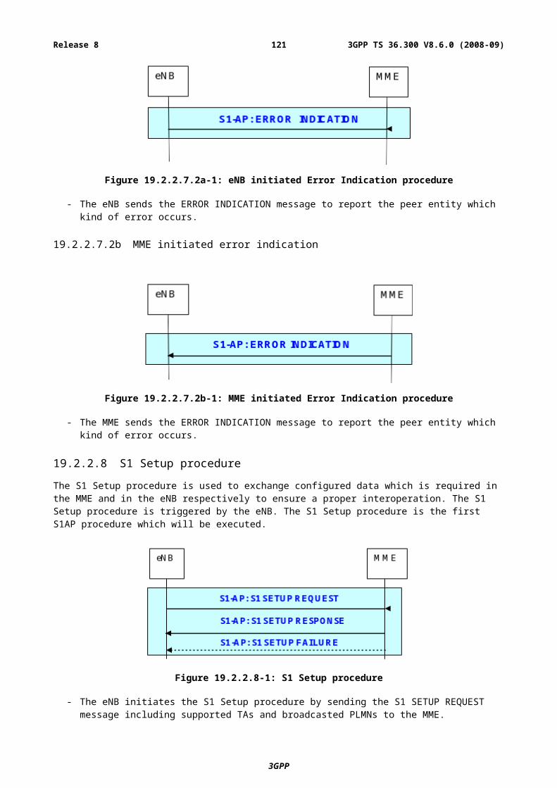
Annex D (informative):MBMS
D.1 MBMS control & functionsThe E-UTRAN supporting MBMS comprises eNBs and co-ordinating functions.
The functions hosted by the eNB may be:
- Scheduling and transmission of MBMS control information;
- Scheduling of single-cell MBMS transmissions;
- Transmission of single-cell and multi-cell MBMS services;
- Radio bearer control for MBMS.
The co-ordinating functions may include:
- Distribution of MBMS services;
- Co-ordination of multi-cell MBMS transmissions;
- MBMS EPS bearer control.
It is FFS which node in E-UTRAN performs the co-ordination functions.
D.2 MBMS transmissionA point-to-multipoint radio bearer is used to carry MBMS traffic. It is FFS whether a point-to-point radio bearer is also used to carry MBMS traffic or not. Improvements for single-cell MBMS transmission (e.g. HARQ) and MCS that would enable potential removal of p-t-p transmissions for MBMS are FFS.
A frequency layer can be dedicated to MBMS transmissions:
- When a cell belongs to a frequency layer dedicated to MBMS transmissions (MBMS-dedicated cell):
- The MBMS transmission (MTCH and MCCH) occurs on MCH or DL-SCH;
- No uplink or counting mechanism supported;
- No support for unicast data transfer in the cell;
- The occurrence of paging messages on the frequency layer dedicated to MBMS transmission is FFS:
- If paging messages were allowed, the UE could answer in a non-E-UTRA cell e.g. UTRA cell (FFS);
- The possible multi-cell p-t-m transmission with MBSFN operation on the MCH of the MBSFN area is semi-statically configured e.g. by O&M.
- Single-cell p-t-m transmission is possible.
- When a cell does not belong to a frequency layer dedicated to MBMS transmissions (MBMS/Unicast-mixed cell):
- Transmission of both unicast and MBMS transmissions in the cell is done in a co-ordinated manner on DL-SCH and or MCH+DL-SCH (FFS);
- The possible MBSFN operation on the MCH of the MBSFN area is semi-statically configured e.g. by O&M; or the SFN area is dynamic and may be based on counting mechanisms (FFS).
- Counting is possible (FFS);
3GPP
3GPP TS 36.300 V8.6.0 (2008-09)121Release 8
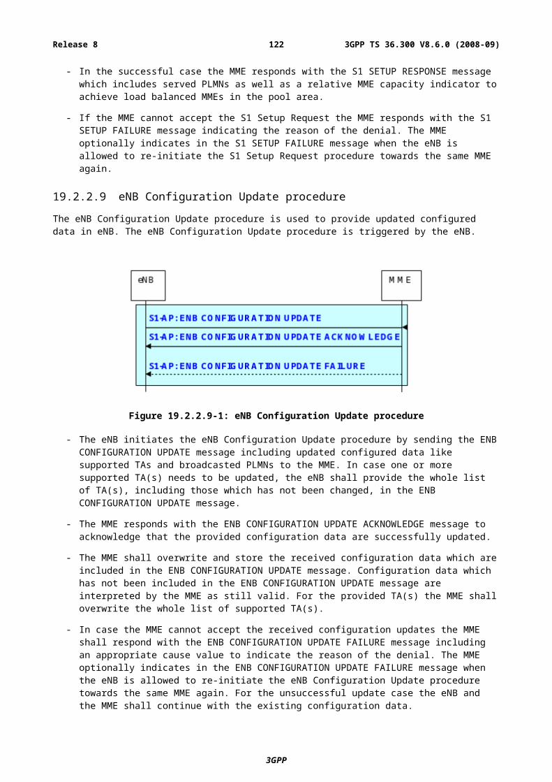
- P-t-p transmission on DL-SCH is FFS.
There are two types of MBMS transmissions in E-UTRA/E-UTRAN:
a) Single-cell transmission (no MBSFN operation):
- The MBMS service, e.g. message distribution, is transmitted only on the coverage of a specific cell;
- The MBMS service (MTCH and MCCH) may be transmitted on DL-SCH or MCH (FFS);
- Combining of MBMS transmission from multiple cells is not supported;
- Counting for switching between p-t-p and p-t-m radio bearer may be supported (FFS);
- The p-t-m/p-t-p switching points are either dynamically decided based on counting mechanism or semi-statically configured by O&M (FFS).
b) Multi-cell transmission (MBSFN operation):
- The MBMS service (MTCH and MCCH) is transmitted on MCH;
- Combining is supported with SFN;
- Synchronous transmission.
The BCCH indicates where the MCCH(s) are:
- One (or none) MCCH per cell for cell specific transmission;
- MCCH(s) sent in MBSFN area for non-cell specific transmission.
Having a feedback mechanism for MTCH transmission is FFS: statistical feedback, TTI based NACK or something else. Also is FFS if the re-transmission is a single cell transmission in all cases.
D.3 Deployment ScenariosIn terms of deployment scenarios of MBMS in E-UTRAN, the following alternatives can be listed:
- Carrier type: dedicated vs. mixed carrier;
- MBSFN transmission: multi-cell vs. single-cell transmission;
- Radio bearer type: p-t-m vs. p-t-p;
- Counting: yes or no;
- Audience measurement: yes or no;
- ON/OFF control of MBMS service delivery: yes or no;
- PTP / PTM radio bearer switching: yes or no;
Table D.3-1 below lists the combinations of the above alternatives that are specifically supported in E-UTRAN:
Table D.3-1: MBMS Deployment Scenarios
# Carrier Transmission RB Counting Comments1 dedicated multi-cell p-t-m no From 1 to n cells
Audience measurement (FFS)2 mixed multi-cell p-t-m no Audience measurement (FFS)3 mixed single-cell p-t-m yes
3GPP
3GPP TS 36.300 V8.6.0 (2008-09)122Release 8
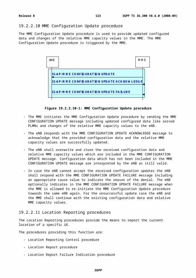
D.4 MCCH InformationThe following information types are proposed as candidates for inclusion on MCCH. Stage 3 work may group certain information into, for example, modified services information and unmodified services information, and to avoid duplication and reduce transmission size, group parameter sets into, for example, indexed common services information. It is FFS whether the information of the same type will map to the same IE. The information types described here are linked to the following use cases:
1. UE camping in a cell monitoring for session start(s).
2. UE powering up, entering a cell or on activation of a service, seeking to detect whether a service that it requires is ongoing in the cell.
3. UE commencing to receive a service or required to change parameters following reconfiguration.
4. UE receiving an MBMS service and monitoring for session stop, recounting indication, reconfiguration indication and revised parameters. Possibly also dynamic scheduling.
5. UE performing a cell reselection seeking information that aids service continuity.
Table D.4-1: Potential MCCH Information Types
Information Type Use Case
Service and session identitiesSession start – own layerSession start – another (mixed or dedicated) layer (FFS) Ongoing or by request (FFS) - own layerOngoing or by request - another (mixed or dedicated) layer (FFS)
Short identities indexing service identities
112
2, 53
2,3,4,5
Service parameters – radio bearer information, physical channel configuration information, scheduling information (Note 1)
For services (MTCH) transmitted on DL-SCHFor services (MTCH) transmitted on MCH
3, 4, 53, 4, 5
Required action – whilst receiving a serviceSession stop indicationReconfiguration indicationRecounting indication (FFS)Change state (FFS)
Required action – service accessMake service request (FFS)Change state (FFS)
444
42, 52
332
Counting control information:For services transmitted on DL-SCHFor services transmitted on MCH (FFS)
Single-cell MTCH feedback control (FFS)
3, 43, 43, 4
Indication of the existence of other layers (dedicated, mixed) (FFS)Other frequency layer parameters (FFS)
1, 2,53
1, 2, 53
Neighbour cell information e.g. service existence, MTCH or MCCH parameters (FFS)MBSFN area edge cell indication or identity (FFS)
55
Parameters that identify how to receive scheduling information(FFS) 3, 4, 5S-MCCH parameters and scheduling (on P-MCCH)MCCH modification indication (FFS)
2, 4, 3, 51, 4
3GPP
3GPP TS 36.300 V8.6.0 (2008-09)123Release 8
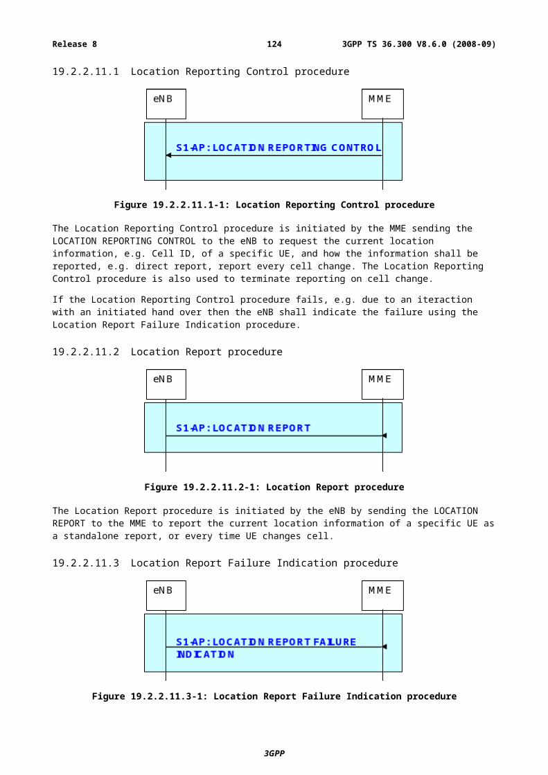
Note 1: Scheduling information may take two forms, e.g. semi-static scheduling of the TTIs in which MTCH transmissions can take place and short-term scheduling which indicates whether transmissions take place within these TTI, e.g. for DRX (FFS).
Note 2: The case represented here is the FFS scenario where an eNB requires a UE to enter RRC Connected state in order to receive a service. This relates to a single-cell transmission e.g. to perform feedback. A UE might be required to do this on taking up the service, on transferring into a cell whilst receiving the service or whilst receiving the service when in a cell.
Note 3: The use case represents case 2 of the service continuity requirements as described in section 15.4.
Annex E (informative):Drivers for Mobility ControlTable E-1 lists the drivers, limitations, and their applicability to intra-frequency, inter-frequency, and inter-RAT scenarios. Each driver and limitation is described in Section E.1 and E.2, respectively. For inter-frequency and inter-RAT scenarios, the applicable drivers are shown in detail for IDLE/ACTIVE modes and their transitions in Section E.3.
Table E-1: Drivers and limitations for mobility control and applicability to mobility scenarios.
# Drivers/limitations Intra-frequency
Inter-frequency
Inter-RAT
Drivers 1 Best radio condition X X X2 Camp load balancing X X3 Traffic load balancing X X4 UE capability X X5 Hierarchical cell structures X X6 Network sharing X X7 Private neworks/home cells X X8 Subscription based mobility control X X9 Service based mobility control X X
10 MBMS X XLimitations 11 UE battery saving X X X
12 Network signalling/processing load X X X13 U-plane interruption and data loss X X X14 OAM complexity X X X
As shown in Table E.1, the applicable drivers depend on the mobility scenario, i.e., intra-frequency, inter-frequency, and inter-RAT:
- Intra-frequency mobility: intra-frequency mobility is the most fundamental, indispensable, and frequent scenario. With the frequency reuse being one in E-UTRAN, applying any driver other than the “best radio condition” to intra-frequency mobility control incur increased interference and hence degraded performance. As such, only the “best radio condition” driver is applicable to intra-frequency mobility. Note that the exact definition of “intra-frequency mobility” is yet unclear, and shall be clarified with RAN1.
- Inter-frequency mobility: as in UTRAN, an operator may have multiple carriers/bands for E-UTRAN working in parallel. The use of these frequency layers may be diverse. For example, some of these frequency layers may utilise the same eNB sites and antenna locations (i.e., co-located configuration), whereas some may be used to form a hierarchical cell structure (HCS), or even be used for private networks. Some frequency layers may provide MBMS services, while some may not. Moreover, E-UTRAN carriers/bands may be extended in the future to increase capacity. For example, as E-UTRAN gains popularity, an operator may decide to convert existing UTRAN carriers into E-UTRAN ones. The operator may also acquire additional carriers/bands, that are not necessarily contiguous. As a consequence, different UE band capabilities may coexist and different carriers/bands may operate at different areas within a network. The E-UTRAN standard should readily support such carrier/band extensions and diverse network configurations, providing flexibility and efficiency. Therefore, a number of drivers apply to inter-frequency mobility control, in addition to the “best radio condition” driver.
3GPP
3GPP TS 36.300 V8.6.0 (2008-09)124Release 8
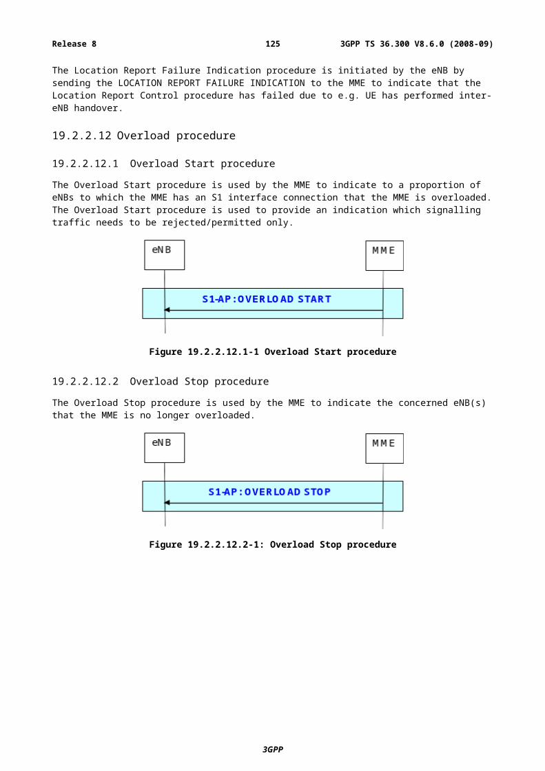
- Inter-RAT mobility: the aspects that need to be considered for inter-RAT are similar to those for inter-frequency. For mobility solutions to be complete with the inter-RAT drivers, relevant updates would be necessary on the legacy (UTRAN/GERAN) specifications. This will add to the limitations, which are evidently more effective in inter-RAT. Although the drivers/limitations need to be assessed per objective RAT (UTRAN/GERAN), the solutions should be made common as much as possible to reduce any complexity.
E.1 DriversThe drivers for mobility control are described in the following sections.
E.1.1 Best radio conditionThe primary purpose of cell reselection, regardless of intra-frequency, inter-frequency, or inter-RAT, is to ensure that the UE camps on/connects to the best cell in terms of radio condition, e.g., path loss, received reference symbol power, or received reference symbol Es/I0. The UE should support measurements to suffice this aspect. For E-UTRAN cells, the frequency domain scheduling and channel/symbol mapping may have some implications to designing the measurements and reselection/reporting criteria. The UE would also have to check that the selected cell falls within the accessible range (in terms of signal strength and possibly also in terms of propagation delay, i.e., check if it falls within the dynamic range of timing advance, FFS).
E-UTRAN should support good mobility even when the radio environment changes suddenly, e.g., when the UE enters a tunnel or in a Manhattan-like street cell scenario. It should be discussed whether a special mechanism is needed to cope with such sudden changes in radio environment or it can be handled with good radio network planning practices. In either case, the system design should minimise any side effects of counteracting the sudden changes in the radio environment (e.g., ping-pongs).
For inter-frequency/RAT mobility, the UE needs idle gaps to perform measurements on other frequency layers/RATs. In addition, for inter-RAT, E-UTRAN measurements while the UE is in another RAT (UTRAN/GERAN) need to be supported. It should be discussed whether in certain cases (e.g., co-located E-UTRAN cells within the same frequency band) the measurements can be omitted.
E.1.2 Camp load balancingThis is to distribute idle state UEs among the available bands/carriers/RATs, such that upon activation, the traffic loading of the bands/carriers/RATs would be balanced. At least the path loss difference between different bands should be compensated to avoid UEs concentrating to a certain frequency layer (e.g., lower frequency bands due to the propagation nature). A deliberate mechanism would be necessary to avoid UEs concentrating to a certain RAT (e.g., E-UTRAN). Various solutions have been presented including the use of Qoffset and an approach of limiting the frequency layers for camping.
For inter-RAT, this driver also includes the aspect of balancing the loading of core network nodes of different RATs. Nevertheless, for intra- E-UTRAN, the core network load aspect is out of scope, since MME/Serving Gateway relocation by itself should not cause any radio mobility procedure (but only NAS procedures like NAS ID and security updates).
E.1.3 Traffic load balancingThis is to balance the loading of active state UEs, using redirection for example. In E-UTRAN, traffic load balancing is essential because of the shared channel nature. That is, the user throughput decreases as the number of active UEs in the cell increases, and the loading directly impacts on the user perception. A solution is desired that causes minimum impact on the user perception. This implies that inter-layer transitions are preferably done during data inactivity (e.g., DRX) or transition to the idle state. Although this driver is also applicable to inter-RAT, for inter-RAT, the “service dependent control” driver may be more dominant than the load balancing aspect.
E.1.4 UE capabilityAs E-UTRAN bands/carriers may be extended in the future, UEs having different band capabilities may coexist within a network. It is also likely that roaming UEs have different band capabilities. Overlaying different RATs adds to this variety. The mobility solution should cope with the coexistence of various UE capabilities in an efficient manner.
3GPP
3GPP TS 36.300 V8.6.0 (2008-09)125Release 8
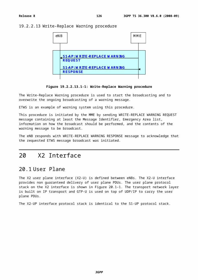
E.1.5 Hierarchical cell structuresAs in UTRAN, hierarchical cell structures (HCS) may be utilised in E-UTRAN to cover for example, indoors and hot spots efficiently. It is possible that E-UTRAN is initially deployed only at hot spots, in which case this driver becomes essential for inter-RAT, not just for inter-frequency. Another use case would be to deploy a large umbrella cell to cover a vast area without having to deploy a number of regular cells, while providing capacity by the regular cells on another frequency. While HCS can be seen as a solution to reduce measurement and signalling loads, to optimise HCS usage, mobility control should take into account the UE mobility (e.g., speed). This however implies that sufficient mobility detection is also required. Although HCS is not addressed as a mobility driver for intra-frequency mobility, intra-frequency HCS deployment should not be restricted.
E.1.6 Network sharingAt the edge of a shared portion of a network, it will be necessary to direct UEs belonging to different PLMNs to different target cells. The mobility solutions in both idle and active states should therefore support differentiation between UEs of different operators.
E.1.7 Private networks/home cellsCells that are part of a sub-network should prioritise the camping on that sub-network. UEs that do not belong to private sub-networks should not attempt to camp or access them. Although this could be resolved by the use of forbidden TAs as in UTRAN, a more deliberate mechanism may be needed as some of these sub-networks could be very small, e.g., one home.
E.1.8 Subscription based mobility controlThis mobility driver aims to limit the inter-RAT mobility for certain UEs, e.g., based on subscription or other operator policies. The system should provide means to disallow access on certain RATs (including E-UTRAN) as done with "LA reject" in legacy systems. It should be possible for the operator to trigger a subsequent UE action such as a cell or PLMN selection.
E.1.9 Service based mobility controlAn operator may have different policies in allocating frequencies to certain services. For example, the operator may concentrate VoIP UEs to a certain frequency layer or RAT (e.g., UTRAN or GERAN), if evaluations prove this effective. UEs requiring higher data rates may better be served on a frequency layer or RAT (e.g., E-UTRAN) having a larger bandwidth. The operator may also want to accommodate premium services on a certain frequency layer or RAT, that has better coverage or larger bandwidth.
This driver is essential for inter-RAT, due to the different QoS levels provided by different RATs. The nature of the service being requested (e.g., QoS and traffic behaviour) should be considered in controlling mobility, so that services are accommodated in the best suitable RAT. Note that such service dependent control shall only be based on network decisions and not on UE decisions (i.e., no UE based service dependent cell reselection), except for MBMS scenarios.
E.1.10 MBMSAs MBMS services may be provided only in certain frequency layers, it may be beneficial/necessary to control inter-frequency/RAT mobility depending on whether the UE receives a particular MBMS service or not. For MBMS scenarios only, UE based service dependent cell reselection might be considered acceptable. This aspect also depends on the UE capability for simultaneous reception of MBMS and unicast.
E.2 Limitations for mobility controlWhile the issues mentioned above drive E-UTRAN towards “aggressive” mobility control, the limiting factors also have to be considered. The factors listed below apply to all intra-frequency, inter-frequency, and inter-RAT mobility scenarios.
3GPP
3GPP TS 36.300 V8.6.0 (2008-09)126Release 8
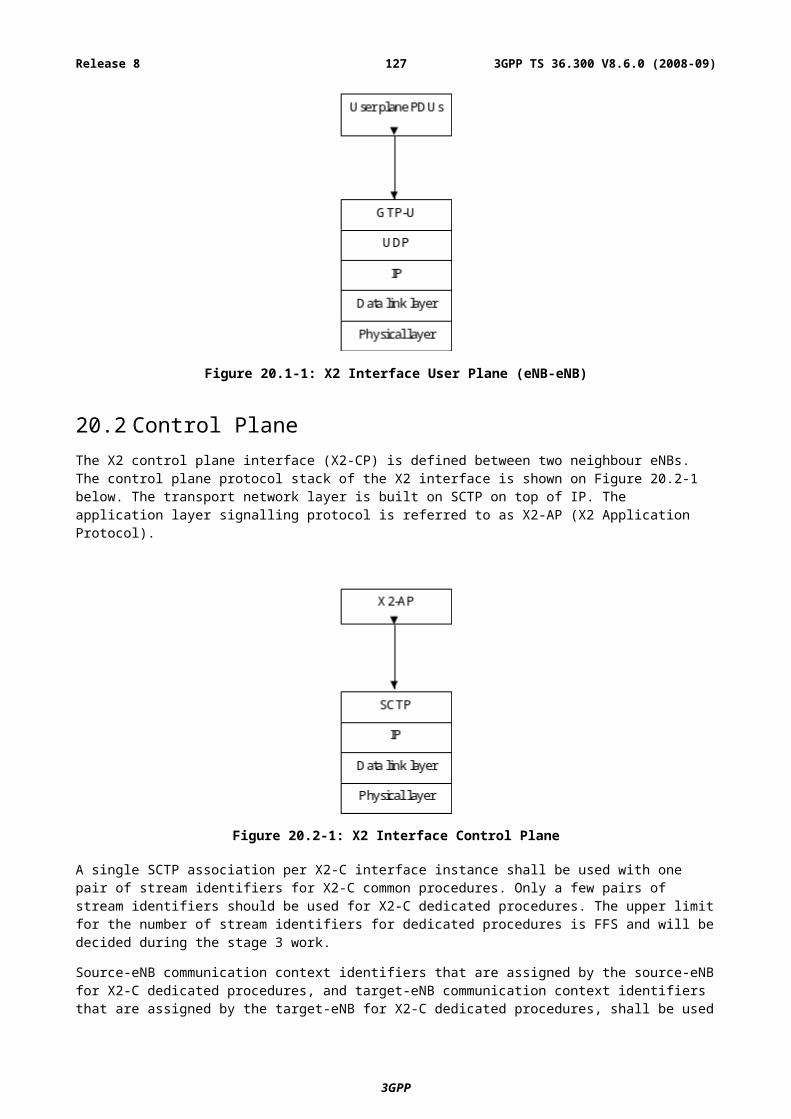
E.2.1 UE battery savingThe mobility solution should not consume excessive UE battery, e.g., due to measurements, measurement reporting, BCH reception, or TA update signalling. This could be achieved for example by setting appropriate measurement rules such as S-criteria, hysteresis, and time-to-trigger. Adaptive control of some measurement/mobility parameters (e.g., based on DRX, cell size, or mobility) may also be considered as a countermeasure. To reduce TA update signalling, TA allocations can be differentiated depending on the UE speed or the mobility vector, on top of appropriate TA planning. Effects on additional delays (e.g., paging) should also be investigated if means such as “long DRX” are used to achieve these savings.
It should be investigated together with RAN4 if a coupling between measurements accuracy and DRX (as in UTRAN) is also acceptable for E-UTRAN.
E.2.2 Network signalling/processing loadThe mobility solution should not cause excessive network signalling/processing load. This includes over-the-air signalling, S1/X2 signalling, and processing load at network nodes. Unnecessary handovers and cell reselections should be avoided, and PCH and BCH signalling, as well as dedicated signallings, should be limited. This could be achieved by similar countermeasures as for UE battery saving.
E.2.3 U-plane interruption and data lossU-plane interruption and data loss caused by the mobility solution should be limited. The required QoS should be satisfied in any case.
E.2.4 OAM complexityThe mobility solution should not demand excessive efforts in operating/maintaining a network. For example, when a new eNB is added or an existing eNB fails, the mobility solution should not incur excessive efforts to set up or modify the parameters. Means should be studied to integrate the mobility solutions in the concept of “self-optimisation” to minimise manual processes. Reducing the neighbour list information in E-UTRAN would also be a countermeasure to this requirement.
E.3 Inter-frequency/RAT drivers
E.3.1 Mobility control during IDLE modeThis is to control the mobility of UEs during IDLE mode, i.e., cell reselection. Table E.3.1-1 summarises applicability of the drivers for different inter-frequency/RAT scenarios and necessary features to support the drivers. Note that in Tables E.3.1-1, E.3.2-1, E.3.3-1, E.3.4-1, an “X” in the table indicates that the driver is essential, whereas an "(X)" indicates that the driver may be reduced in support depending on the complexity incurred. Furthermore in Tables E.3.1-1, E.3.2-1, E.3.3-1, E.3.4-1, the following abbreviations are used:
- LL: LTE to LTE inter-frequency mobility;
- LU: LTE to UTRAN inter-RAT mobility;
- UL: UTRAN to LTE inter-RAT mobility;
- LG: LTE to GERAN inter-RAT mobility;
- GL: GERAN to LTE inter-RAT mobility.
Table E.3.1-1: Mobility control during IDLE (cell reselection).
#Drivers
ApplicabilityNecessary features to support driversLL LU UL LG GL
1 Radio condition X X X X X Inter-frequency/RAT measurements (solutions to
3GPP
3GPP TS 36.300 V8.6.0 (2008-09)127Release 8
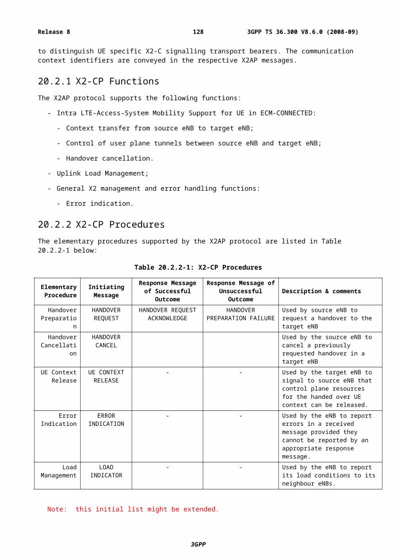
mitigate measurement load should be considered, e.g., S-criteria);Cell reselection and reselection criteria.
2 Camp load balancing
X X X (X) (X) Mechanism to prioritise cell reselection to certain layer/RAT, depending on the loading of layers/RATs;Load information exchange (not needed if balancing is inadaptive, i.e., only based on subscriber penetration on each band/RAT.).
3 Traffic load balancing
N/A
4 UE capability (X) X X X X Mechanism to prioritise cell reselection to certain layer/RAT, depending on the UE capability.
5 HCS (X) (X) (X) (X) (X) Mobility detection (e.g., number of crossed cells);Mechanism to prioritise cell reselection to certain layer/RAT, depending on the UE speed (e.g., HCS mechanism as in UTRAN).
6 Network sharing X X X X (X) Mechanism to direct the UE to the appropriate PLMN at a network sharing border;Mechanism to restrict UE measurements and reselection to cells that are entitled to access.
7 Private networks / home cells
X (X) X (X) Mechanism to prioritise reselection to private/home cells that are entitled to access;Mechanism to restrict UE measurements and reselection to cells that are entitled to access;Other unidentified features, FFS.
8 Subscription / Policy based
mobility control
X X X (X) (X) Mechanism to prioritise cell reselection to certain layer/RAT, depending on the subscription information or any other operator policy (e.g., for LL there may be cases where an operator has policy in allocating UEs to certain frequencies due to different carrier bandwidths).
9 Service based mobility control
N/A
10 MBMS X (X) X Mechanism to prioritise cell reselection to the layer/RAT, depending on whether the UE requires reception of a certain MBMS transmission.
E.3.2 Mobility control upon IDLE to ACTIVE transitionThis is to control the mobility of UEs upon IDLE to ACTIVE transition, i.e., redirection upon RRC or U-plane establishment. Table E.3.2-1 summarises applicability of the drivers for different inter-frequency/RAT scenarios and necessary features to support the drivers.
Table E.3.2-1: Mobility control upon IDLE to ACTIVE transition (redirection upon RRC/U-plane establishment)
# DriversApplicability
Necessary features to support driversLL LU UL LG GL1 Radio condition (X) (X) Inter-frequency/RAT measurements (during
IDLE mode or upon IDLE to ACTIVE transition) and measurement reporting upon RRC establishment (it should be investigated whether measurements can be omitted in some or all cases, e.g., co-located cells).
2 Camp load balancing
N/A
3 Traffic load balancing
X (X) (X) (X) Redirection to a certain layer/RAT (cell) upon RRC establishment, depending on the loading of layers/RATs;Load information exchange (not needed if balancing is inadaptive, i.e., only based on subscriber penetration on each band/RAT).
3GPP
3GPP TS 36.300 V8.6.0 (2008-09)128Release 8
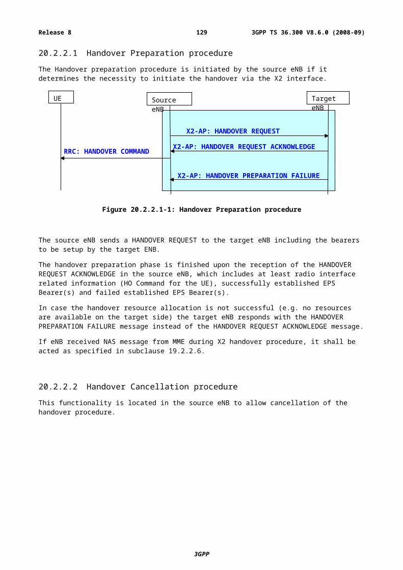
4 UE capability X (X) (X) Redirection to a certain layer/RAT (cell) upon RRC establishment, depending on the UE capability.
5 HCS N/A6 Network sharing (X) (X) (X) (X) Redirection to a certain layer/RAT (cell) of the
preferred PLMN, upon RRC establishment.7 Private
neworks / home cells
(X) Redirection from a certain private/home cell.
8 Subscription / Policy based
mobility control
X X (X) (X) (X) Redirection to a certain layer/RAT (cell) upon RRC establishment, depending on the subscription information (if available upon establishment) or any other operator policy.
9 Service based mobility control
X X (X) (X) (X) Redirection to a certain layer/RAT (cell) upon RRC establishment, depending on the requested service (if the service information is available upon establishment).
10 MBMS N/A
E.3.3 Mobility control during ACTIVE modeThis is to control the mobility of UEs during ACTIVE mode (ECM-CONNECTED or UTRAN RRC Connected), i.e., handover. Table E.3.3-1 summarises applicability of the drivers for different inter-frequency/RAT scenarios and necessary features to support the drivers.
Table E.3.3-1: Mobility control during ACTIVE (handover)
# DriversApplicability
Necessary features to support driversLL LU UL LG GL1 Radio condition X X X X (X) Gap assisted inter-frequency/RAT
measurements (network controlled);Measurement reporting and reporting criteria;Inter-frequency/RAT handover (UE assisted network controlled).
2 Camp load balancing
N/A
3 Traffic load balancing
X (X) (X) (X) Inter-frequency/RAT handover (network controlled);Load information exchange (not needed if balancing is inadaptive, i.e., only based on subscriber penetration on each band/RAT).
4 UE capability (X) (X) (X) (X) Inter-frequency/RAT handover (network controlled), depending on the UE capability.
5 HCS (X) (X) (X) Mobility detection (e.g., number of crossed cells);Inter-frequency/RAT handover (network controlled), depending on the UE speed.
6 Network sharing X X X X Inter-frequency/RAT handover (network controlled) to a cell of the appropriate PLMN at network sharing border;Mechanism to restrict UE measurements to cells that are entitled to access.
7 Private networks/home cells
X X X X X Inter-frequency/RAT handover (network controlled) to a private/home cell on another layer/RAT, where the UE is entitled to access;Mechanism to restrict UE measurements and reselection to cells that are entitled to access;Other unidentified features, FFS.
8 Subscription / Policy based
mobility control
(X) X X X X Inter-frequency/RAT handover (network controlled), depending on the subscription information or any other operator policy.
9 Service based mobility control
(X) X X X X Inter-frequency/RAT handover (network controlled), depending on the service or combination of services being used or requested.
3GPP
3GPP TS 36.300 V8.6.0 (2008-09)129Release 8
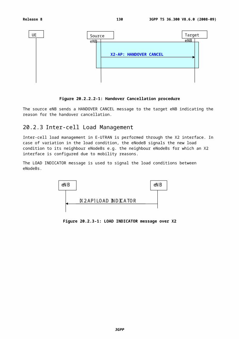
10 MBMS X X X Inter-frequency/RAT handover (network controlled), depending on whether the UE requires reception of a certain MBMS transmission.
E.3.4 Mobility control upon ACTIVE to IDLE transitionThis is to control the mobility of UEs upon ACTIVE to IDLE transition, i.e., redirection upon RRC or U-plane release. Table E.3.4-1 summarises applicability of the drivers for different inter-frequency/RAT scenarios and necessary features to support the drivers.
Table E.3.4-1: Mobility control upon ACTIVE to IDLE transition (redirection upon RRC/U-plane release)
# DriversApplicability
Necessary features to support the driverLL LU UL LG GL1 Radio condition X X X X X Gap assisted inter-frequency/RAT
measurements (it should be investigated whether measurements can be omitted in some or all cases, e.g., co-located cells), ORCell search upon redirection.
2 Camp load balancing
X X X (X) (X) Redirection to a certain layer/RAT upon RRC release, depending on the loading of layers/RATs;Load information exchange (not needed if balancing is inadaptive, i.e., only based on subscriber penetration on each band/RAT).
3 Traffic load balancing
N/A
4 UE capability X X X (X) (X) Redirection to a certain layer/RAT upon RRC release, depending on the UE capability.
5 HCS N/A6 Network sharing X X X X Redirection to a certain layer/RAT of the
preferred PLMN, upon RRC release.7 Private networks
/ home cellsN/A
8 Subscription / Policy based
mobility control
X X X (X) (X) Redirection to a certain layer/RAT upon RRC release, depending on the subscription information or any other operator policy.
9 Service based mobility control
(X) (X) (X) Redirection (or maintaining) to a certain layer/RAT upon RRC release, depending on the service that has been used (predicting that the UE uses the same service in the future).
10 MBMS (X) (X) (X) Redirection to a certain layer/RAT upon stop of an MBMS service reception.
3GPP
3GPP TS 36.300 V8.6.0 (2008-09)130Release 8
Annex F (informative):Mobility and Access Control Requirements associated with Closed Subscriber Group (CSG) Cells
F.1 Access ControlThe following description is provided from the perspective of the Home cell deployment, and is used as an example to understand the general requirements of Closed Subscriber Group (CSG) Cells.
If an operator uses the 2G or 3G systems for a deployment in a home, there are some limitations imposed by mandating that only a UE from a specific User Group can access the cell. This access restriction is needed because some backhaul links for this type of deployment are not considered to provide adequate QoS to support a large numbers of UEs, or there may be regulatory issues with sharing the backhaul link/eNB access in that location, and additionally the backhaul maybe owned by the subscriber and they may not be happy to share the link with other subscribers.
In 3G, the Access Control would work based on the Location Updating or Routing Area Updating Reject for the LA or RA which is being signalled on the cell. Each unique User Group would require its Location Area ID, however the LAC of the LA ID is only 2 octets, which needs to be shared with the normal LAs of the PLMN.
There is an additional drawback with this solution in 3G, which is that all terminals would attempt to perform the Location Updating procedure on a cell advertising a LA not on the list of forbidden LAs in the UE. The network would reject the location updating procedure of those UEs which are not in the User Group associated with the LA. This would lead to the scenario in a densely populated area, where a UE moving down the street could attempt to access a home cell at each house, before being rejected causing a wastage of battery in the terminal, and unnecessary signalling/processing load in the core network.
1. A UE should not camp on or access a CSG Cell if it is not part of the User Group which is allowed to access that CSG Cell.
It shall be possible to update the User Group associated with a specific Home-eNB, e.g. based on request by the registered owner of the Home-eNB, under the supervision of the network operator. When a subscriber is added to the User Group for the Home-eNB, the UE of the newly added subscriber should be able to (almost) immediately camp on the cell(s) of Home-eNB and then may acquire service through the Home-eNB. This is especially important in the deployment scenario where this subscriber has no other means to access the network, i.e. there is no Macro-layer coverage available. For this it might be necessary to update the list of allowed CSG cells for a particular UE by network signalling or other means.
2. The subscriber registered as the owner of a CSG Cell or group of Cells, under supervision of the operator, shall be able to control/modify quickly which other subscribers form part of the User Group associated with its CSG Cell(s).
F.2 MobilityThe Home-eNB/CSG cells should form part of the network of the operator, and therefore the design needs to support mobility of UEs between the Macro-Layer network and the Home-eNB/CSG cells. In the following text, what is called Macro layer encompasses all the cells which are not from the CSG being considered i.e. it is not about their size/coverage but the fact that they are not closed.
3. The system shall support bidirectional handover between CSG Cells and any eNodeB (E-UTRAN) or RNC (UTRAN) or BSS (GERAN) or with another CSG Cell of the same or different CSG.
The Home-eNBs will be deployed to improve network coverage, improve network capacity as well as offer differential billing models. As the User billing could be dependent on whether the UE is using the Home-eNB, it is important that the UE when it is range of the Home-eNB automatically camps on the Home-eNB.
4. It shall be possible to allow UEs which are allowed to access a given CSG cell, to prioritise their camping towards the CSG Cells when in coverage of the CSG cells. To achieve this it should be possible either to set the reselection parameters accordingly or other means should allow this.
3GPP
3GPP TS 36.300 V8.6.0 (2008-09)131Release 8
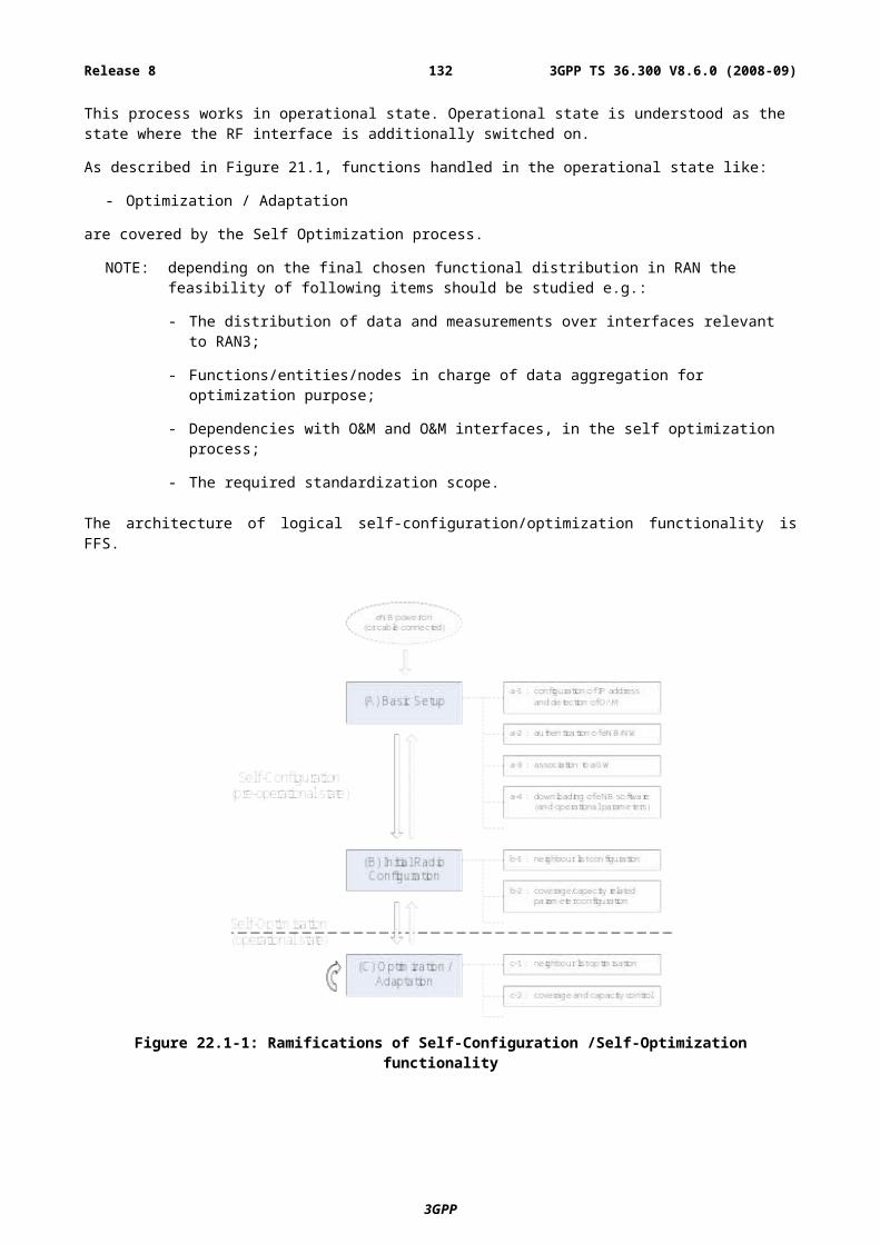
It is important that UEs camped on the Home-eNB do not cause excessive signalling load or processing load if/when the UE moves frequently between the Macro-Layer network and the Home-eNB.
5. The system shall avoid excessive signalling and processing load from a UE frequently reselecting in LTE Idle between the CSG Cells and the non-CSG cells of eNodeB (E-UTRAN) or RNC (UTRAN) or BSS (GERAN).
As discussed above, the Home-eNBs will have an associated User Group describing which UEs can access the Home-eNB. The handover procedures needs to take the User Group of the Target Home-eNB into account when deciding whether to handover a UE to a specific Home-eNB. The solution for the mobility to/from the Home-eNB should avoid unnecessary signalling between the RAN nodes.
6. The handover procedures shall take into account whether a UE is part of the User Group of the target CSG Cell. The mobility procedures should allow for prioritisation of the CSG Cells in ECM-CONNECTED when the UE enters coverage of a CSG Cell and the UE is part of the User Group of this cell.
As the number of Home-eNBs in the network will become large, the proportion of measurements made by a UE which could be wasted may become large, to the point where it affects the mobility performance of the UE/system, as well as draining the battery of the UE. It is therefore necessary for the UE to be able to avoid unnecessary measurements of Home-eNBs where the UE does not belong to the User Group of the Home-eNB.
7. It shall be possible to minimise the quantity of measurements which UEs perform on CSG Cells, if the UE does not belong to the User Group of a specific CSG Cell.
Due to the high number of Home-eNBs and the nature of their deployment, it would not be practical to change the configuration for the mobility procedures (measurements, handover, etc.) in the macro layer nodes when a Home-eNB is deployed/dismissed.
8. The mobility procedures shall allow a large number of (small) CSG Cells to be deployed within the coverage of e-UTRAN, UTRAN and GERAN macro-layer cells. Deployment of (additional) CSG Cells shall not require reconfiguration of other eNodeB (E-UTRAN) or RNC (UTRAN) or BSS (GERAN).
In order to minimise the impact on UEs not allowed to use CSG cells or not allowed to use a particular CSG cell, means shall be provided which allow the UE to either identify prior to cell reselection that the configured neighbour cell is a CSG cell or means shall be provided which do not impact the UEs on the macro cells.
9. The mobility procedures for moving UEs to CSG cells shall minimise impact to other UEs on the same macro cells not entitled to use CSG cells or a given CSG cell.
It is expected that the CSG identity of a Home-eNB is static and this identity can be used by the UE to clearly identify the Home-eNB. In contrast the Physical Cell Identity (PCI) of a Home-eNB might change at power up. For example, a Home-eNB may scan the neighbour environment at every switch on, and a PCI unused by the neighbours can be selected. In most cases this will end up on the same PCI being used, as the neighbour environment did not change. During operation the Home-eNB might also change the PCI on a slow basis, in case high interference is detected. If the PCI changes, mobility shall still be supported without user intervention. It might be necessary that the change is notified to the UEs belonging to the CSG through network signalling or other means.
10. The Physical Cell Identity (PCI) of a Home-eNB might change at each power up of the Home-eNB. Although a change of PCI is expected to be infrequent, if it changes, mobility shall still be supported without user intervention.
The carrier frequency of a Home-eNB might only be changed during Home-eNB power up, out of a preconfigured range of frequencies. Often the pre-configured frequency range would be limited to one. If the frequency is changed, mobility shall still be supported without user intervention.
11. The carrier frequency of a Home-eNB might be changed at power up of the Home-eNB, out of a preconfigured range of frequencies. Often the preconfigured frequency range would be limited to one. Although a change of frequency is expected to be infrequent, if it changes, mobility shall still be supported without user intervention.
3GPP
3GPP TS 36.300 V8.6.0 (2008-09)132Release 8
F.3 Mobility performance guidelinesFor outbound mobility from CSG cells to non-CSG cells, normal mobility procedures shall apply, i.e., network controlled mobility. As such, the normal mobility performance requirements as for non-CSG mobility should apply.
12. For outbound mobility from CSG cells to non-CSG cells, both for idle and active mode mobility, the normal mobility performance requirements as for non-CSG mobility shall apply.
For inbound mobility to CSG cells in active mode, it is important that the overall handover time perceived by the user, i.e., from the time the user arrives at home till the UE is connected to the CSG cell, is sufficiently short, considering that different charging policies may be applicable to CSG. However, this should not cause severe impacts on the battery consumption. It is thought that the time taken depends largely on UE implementation of the autonomous CSG search, as it is expected that the UE will apply means to reduce battery consumption in verifying the location (to trigger CSG search, based e.g., on “fingerprint”). However, this factor is thought to be existent only in the case the CSG cell is deployed on a different frequency as the serving cell, as for intra-frequency case the UE should be able to detect the CSG cell naturally through normal intra-frequency cell search. Therefore, in case of intra-frequency mobility, the handover should be completed in the order of 1 s. In case of inter-frequency mobility, 10-30 s is expected including the autonomous CSG search time.
13. For inbound mobility to CSG cells in active mode, the cell search, CSG identification, and handover process shall be completed in the order of 1 s in case of intra-frequency mobility. In case of inter-frequency mobility, 10-30 s is expected including the autonomous CSG search time.
For inbound mobility to CSG cells in idle mode, in case of intra-frequency mobility, the same requirements as for non-CSG reselection should apply also to inbound reselection to CSG cells. For inter-frequency mobility, the inbound mobility is not as time critical. However, considering applicability of different tariffs and CSG/ Home-eNB identifiers to be displayed on the terminal screen, it is desirable that the UE camps on the suitable CSG cell without excessive delay. It is desirable that inbound cell reselection is possible within 20-60 s. If UE battery consumption becomes a critical issue, this requirement can be revisited.
14. For inbound mobility to CSG cells in idle mode, cell reselection shall be completed as for normal non-CSG reselection in case of intra-frequency mobility. In case of inter-frequency mobility, it is desirable that inbound cell reselection is possible within 20-60 s.
If the PCI or the carrier frequency of the CSG cell changes, the UE shall be able to detect this change autonomously. It is expected that the UE would look for the CSG cell based on the PCI/ carrier frequency as last stored in its memory and based on the fingerprint. Then, the UE would detect absense of the CSG cell from where it was expected, and initiate a full scan of the CSG cell. By checking the global cell identity of detected CSG cells, the UE should eventually find the CSG cell on a new PCI or carrier frequency. Such autonomous procedure shall be completed within [6 min, FFS]. Once the CSG cell has been found, the requirements 12 and 13 shall apply then on.
15. If the PCI or the carrier frequency of the CSG cell changes, the UE shall be able to detect this change within [6 min, FFS]. The performance requirements 11 and 12 shall apply then on.
3GPP
3GPP TS 36.300 V8.6.0 (2008-09)133Release 8
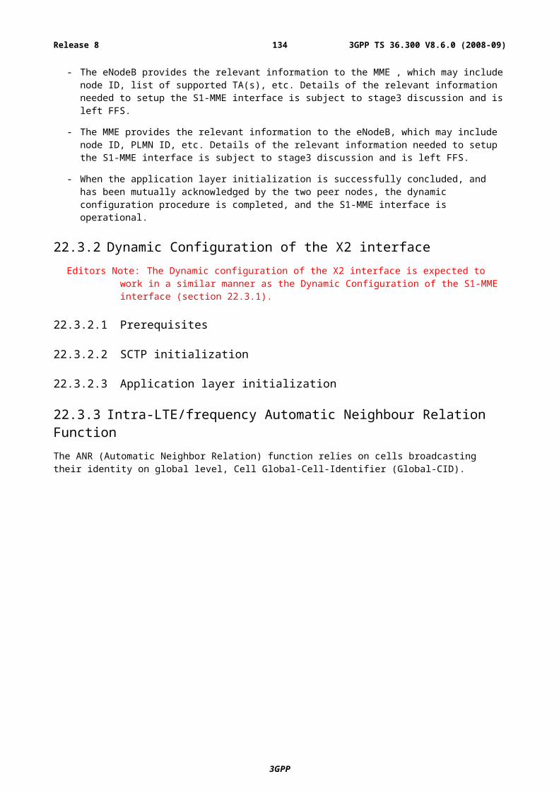
Annex G (informative):Guideline for E-UTRAN UE capabilitiesEach radio access technology has defined specific “classes” of terminals in terms of radio capabilities. E.g. in GPRS the “multislot classes” are defined, in UMTS R’99 different dedicated bearer classes are defined and for HSDPA and HSUPA 12 respectively 6 physical layer categories are defined. The definition of UMTS R’99 UE classes lead to 7 DL classes and 7 UL classes for FDD out of which only 2 DL and 3 UL classes were commercially realized. Furthermore the lower end classes (e.g. 64 UL and 64 DL) disappeared from the market with commercialization of the UMTS networks quite soon. Besides these class definitions a huge number of possible parameter combinations (to achieve certain data rates) exist with UMTS R’99 which lead to the huge number of RAB and RB combinations defined. Further activities in the early phase of UMTS standardization aimed to reduce the number of possible combinations significantly.
For HSDPA two “simple” DL categories (11 & 12) with lowered complexity were defined with the intent to speed up commercialization of HSDPA. Originally those categories should have been removed for Rel-6. Out of the 12 defined categories only approx. 4 will be realized in commercial HSDPA platform products. A similar situation is likely for HSUPA as well as for the combinations of HSDPA/HSUPA.
Generally the aim to mandate certain essential functions/requirements can help to simplify the system definition as well as the realization options (e.g. mandating 20 MHz of DL reception as well as 20 MHz UL transmission bandwidth significantly reduced the E-UTRAN system complexity). Especially mandating certain terminal functions could be useful for the system design if a defined subset of parameter combinations are also supported by the systems, e.g. the eNB scheduler. However, there is also a risk that not all the defined E-UTRA features are deployed in the networks at the time when terminals are made commercially available on the market place. Some features are likely to be rather large and complex, which further increases the risk of interoperability problems unless these features have undergone sufficient interoperability testing (IOT) on real network equipment, and preferably with more than one network in order to improve the confidence of the UE implementation. Thus, avoiding unnecessary UE mandatory features but instead defining a limited set of UE radio classes allows simplification for the interoperability testing.
Given the discussion above, it seems beneficial for the introduction of E-UTRAN to limit the combination of radio capabilities to a clearly defined subset and ensure that a given set of parameters is supported by certain UE classes as well as networks for rapid E-UTRAN deployment. It seems unrealistic to mandate only one single UE class which always mandates the maximum capability.
In order to address the different market requirements (low end, medium and high end), the definition of the following UE classes are proposed:
Table G-1: E-UTRAN UE Classes
Class UL DLA [50] Mbps [100] MbpsB [25] Mbps [50] MbpsC [2] Mbps [2] Mbps
NOTE: For simplification reasons, the table only depict the UE capabilities in terms of uplink and downlink peak data rates supported. However, it should be noted that further discussion on other features is expected once the work progresses.
It may require further discussion whether there be a need for an additional terminal class between 2 Mbps and 50 Mbps classes. It might make sense, since up to 5 MHz band allocations may be rather common in real deployments for several years. This would point to bit rate class of 25 Mbps in DL and 10 Mbps in UL.
The above given data rates are indicative and should be subject for further discussions in 3GPP RAN working groups. Depending on the different solutions to reach those data rates, the target should be to define [3..4] UE classes in different data rate ranges, and other parameters affecting device complexity and cost. The definition of the required parameters/features is for further study for each of the classes. For instance, half-duplex UEs form a specific category that may be frequency band specific.
3GPP
3GPP TS 36.300 V8.6.0 (2008-09)134Release 8
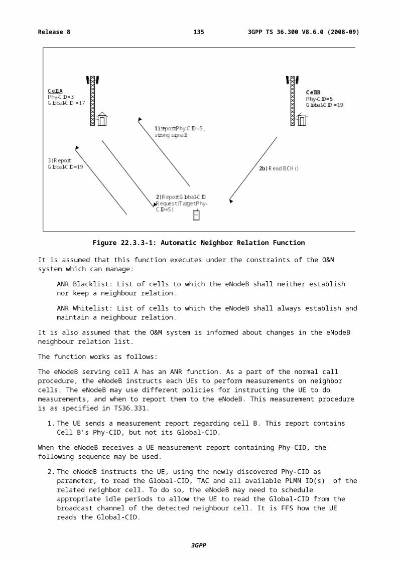
NOTE: the support of half-duplex UEs is mandatory for the eNB where such a category is allowed in the frequency band supported by the eNB.
The aim is to ensure on the one hand that high end E-UTRAN UEs, supporting data rates representing state of the art level and competitive with other radio technologies are defined, while the medium and lower data rates aim to reduce implementation cost for chipset/terminal vendors and allow adoption of most cost efficient solutions for different market segments. It is expected that the support of the high end data rate terminals is ensured from the very beginning.
Another clear exception from this exercise is that on the low end very cheap product implementation is possible (e.g. for the machine-to-machine market or the voice and very low data rate only segment – to substitute GSM in the medium term) while top end performance is needed for data applications in notebooks, wireless gateways (“wireless DSL”), etc.
Another important aspect that must be ensured is that a higher capability UE can be treated in exactly the same way as for a lower capability UE, if the network wishes to do so, e.g., in case the network does not support some higher capability features. In HSDPA, there has been problems in this respect due to 2-stage rate matching in HARQ. Such problems should be avoided in E-UTRAN, and E-UTRAN UE capabilities should provide the compatibility to ease implementation and interoperability testing.
Annex H (informative):PDCCH, PHICH and PUCCH PerformanceThe target qualities on PDCCH, PHICH and PUCCH of E-UTRAN are summarized respectively in the two tables below:
Table H-1: PDCCH and PHICH
Event Target qualityDL scheduling information miss detection (10-2)
UL scheduling grant miss detection (10-2)NACK to ACK error (for UL-SCH) (10-4 – 10-3)ACK to NACK error (for UL-SCH) (10-4 – 10-3)
Table H-2: PUCCH
Event Target qualityACK miss detection (for DL-SCH) (10-2)DTX to ACK error (for DL-SCH) (10-2 – 10-1)
NACK to ACK error (for DL-SCH) (10-4 – 10-3)CQI block error rate FFS (10-2 – 10-1)
3GPP
3GPP TS 36.300 V8.6.0 (2008-09)135Release 8
Annex I (informative):Change history
3GPP
3GPP TS 36.300 V8.6.0 (2008-09)136Release 8
Change history (before approval)Date TSG # TSG Doc. CR Rev Subject/Comment Old New2006-06 RAN2 Ad. R2-062020 First version. 0.0.02006-06 RAN2 Ad. R2-062026 RLC operation clarified;
High priority and low priority SRBs listed in RRC;New section on RRC procedures;Organisation of paging groups explained; New section on Support for self-configuration and self-optimisation.
0.0.0 0.0.1
2006-06 RAN2 Ad. R2-062036 Four possible types of allocation added to section 11;New section for the support for real time IMS services.
0.0.1 0.0.2
2006-08 RAN2#54 R2-062206 Annex B on RRC and MAC control added.Minor editorial clarifications.
0.0.2 0.0.3
2006-09 RAN#34 RP-060603 Section 4 on “Overall Architecture” reorganised;Details on RLC operation included (segmentation, PDU size);Overview of System Information and RACH procedure added.
0.0.3 0.0.4
2006-10 RAN2#55 R2-063012 Ciphering for RRC signalling required in eNB as agreed in SA3;Agreements on RLC operation included: concatenation, discard, polling and status reports;Agreed text proposal in R3-061428 on Self Configuration added to section 19;Context transfer of header compression at UPE relocation listed as FFS.Outline of the RACH procedure described.
0.0.4 0.0.5
2006-10 RAN2#55 R2-063039 Miscellaneous editorial corrections;Agreed text proposal R3-061606 on Current status of E-UTRAN Architecture description added to section 4;Agreed text proposal in R3-061613 on Support for self-configuration and self-optimisation added to section 19.Agreed Physical layer model R2-063031 added to section 5
0.0.5 0.1.0
2006-11 RAN2#56 R2-063656 Annex C on system information classification added (R2-063064);Integrity protection for the control plane only (SA3 agreement);Agreements on PDCP and RLC PDU structure/handling reflected;Decisions on mobility aspects such as load balancing, handover, radio link failure and random access procedure added;Agreed MBMS deployment scenarios listed together with MBMS transmissions and principles from 25.813;Agreed text proposal R3-061936 on Radio Resource Management added to section 15;Agreed text proposal R3-061940 on RAN Sharing added to section 10;Agreed text proposal R3-061943 on Roaming/Area Restrictions in SAE/LTE added to section 10;Agreed text proposal R3-062008 on S1 C-Plane Functions and procedures added to section 18;Agreed text proposal R3-062011 on X2 interface added to section 19.
0.1.0 0.2.0
2006-11 RAN2#56 R2-063680 Incorporation of RAN1 agreement regarding the mandatory support of 20Mhz DL bandwidth for UEs i.e. removal of sub-clause 16.1;Editorial corrections.
0.2.0 0.3.0
2006-11 RAN2#56 R2-063681 Removal of the SA3 agreement on integrity protection for the user plane;Addition of Annex D on MBMS Transmission;Editorial corrections.
0.3.0 0.3.1
2006-11 RAN#34 RP-060806 Clean version 0.3.1 0.3.12007-01 RAN2#56
bisR2-070403 SA3 agreement on integrity protection for the user plane included
(R2-070016);Annex E on drivers for mobility control added (R2-070276);Agreements on the details of the random access procedure added in section 10.1.5 (R2-070365);New section on UL rate control included (R2-070410);RRC security principles listed in section 13.1 (R2-070044);Agreement on MAC security added to section 13 (R2-062100);Basis for DL scheduling put in section 11.1;Assumptions on neighbour cell list included in section 10.
0.3.1 0.4.0
2007-02 RAN2#57 R2-070451 Number of bits for RACH in TDD clarified;Miscellaneous editorial corrections.
0.4.0 0.5.0
2007-02 RAN2#57 R2-071073 Architecture updated according to R3-070397;Agreements from R2-070802.
0.5.0 0.6.0
2007-02 RAN2#57 R2-071120 RACH model for initial access described;Mapping of the BCCH and System Information principles added;Agreements on DRX included in section 12.
0.6.0 0.7.0
2007-02 RAN2#57 R2-071122 Miscellaneous clarifications 0.7.0 0.7.12007-02 RAN2#57 R2-071123 CCCH in DL listed as FFS;
SAE Gateway ID removed from section 8.2;PDCP for the control plane listed as FFS in section 4.3.2;
0.7.1 0.8.0
3GPP
3GPP TS 36.300 V8.6.0 (2008-09)137Release 8
Agreements on intra-E-UTRAN handover procedure included in section 10.1.2 (R3-062020).
2007-03 RAN2#57 R2-071124 Agreement on Radio Access Network Sharing (R2-070551) added to section 10.1.7;Overview of the physical layer (R1-071251) included to section 5;Agreed text proposals on S1 interface included in Section 19 (R3-070289, R3-070402);Agreed text proposal R3-070409 on network sharing included in section 10.1.7;Agreed text proposal R3-070411 on Area Restrictions included in section 10.4;Agreed text proposal R3-070448 on Assembly of Intra-E-UTRAN handover command included in section 10.1.2.1.1;Agreed text proposal R3-070451 on inter RAT HO principles included in section 10.2.2;Agreed text proposal R3-070472 on Addressing on S1-C and X2-C added to sections 19.2 and 20.2;Agreed text proposal R3-070494 on Initial Context Setup Function and Procedure added to section 19;Agreed text proposal R3-070495 on S1 Paging function and procedure added to section 19Figures for mapping between channels split into Uplink and Downlink parts in section 5.3.1 and 6.1.3.
0.8.0 0.9.0
2007-03 RAN#35 RP-070136 S1-U and S1-MME used throughout the document;aGW replaced by EPC when still used;Clean version for information
0.9.0 1.0.0
Change history (after approval)Date TSG # TSG Doc. CR Rev Subject/Comment Old New2007-03 RP-35 RP-070136 - Approved at TSG-RAN #35 and placed under Change Control 1.0.0 8.0.02007-06 RP-36 RP-070399
0001 1
Changes to management-, handover-, paging- and NAS functions, node- synchronization, X2 UP protocol stack, X2 inter cell load management, IP fragmentation, intra-LTE HO, and TA relation to cells in eNB
8.0.0 8.1.0
RP-36 RP-070494 0002 1 Update on Mobility, Security, Random Access Procedure, etc… 8.0.0 8.1.0RP-36 RP-070399 0003 - Update on MBMS 8.0.0 8.1.0
2007-09 RP-37 RP-0706370004 1
Update on Security, System Information, Mobility, MBMS and DRX
8.1.0 8.2.0
RP-37 RP-0706370005 1
Correction of synchronization, handover, trace, eMBMS architecture, and S1 common functions and procedures
8.1.0 8.2.0
2007-12 RP-38 RP-070913 00061
Clean up and update on security, scheduling, mobility, MBMS and DRX
8.2.0 8.3.0
RP-38 RP-070913 0007 Mobility management 8.2.0 8.3.0RP-38 RP-070913 0008 Correction of eMBMS functions and NAS handling during X2
handover8.2.0 8.3.0
RP-38 RP-071048 0009 Update of Stage 2 to incorporate Interworking with cdma2000 8.2.0 8.3.02008-03 RP-39 RP-080192 0010 CR to 36.300 on NAS States, Persistent Scheduling, C-RNTI
Allocation at Handover…8.3.0 8.4.0
RP-39 RP-080192 0011 RAN3 corrections to 36.300 (CR0011) 8.3.0 8.4.02008-05 RP-40 RP-080406 0012 1 Introduction of optimized FS2 for TDD 8.4.0 8.5.0
RP-40 RP-080406 0013 1 System Information, Mobilty, QoS and miscellaneous updates 8.4.0 8.5.0RP-40 RP-080406 0014 - Updates to Stage 2 based on Stage 3 progress on CDMA inter-
working8.4.0 8.5.0
RP-40 RP-080406 0016 1 CR 0016r1 to 36.300 on CSG mobility performance guidelines 8.4.0 8.5.0RP-40 RP-080406 0017 - CR to 36.300 on AS-NAS interaction 8.4.0 8.5.0RP-40 RP-080420 0018 1 RAN3 agreed changes to TS 36.300 8.4.0 8.5.0RP-40 RP-080463 0019 - Network Interface for ETWS support based on CBS solution 8.4.0 8.5.0
2008-09 RP-41 RP-080688 0020 - Correction for Rename of L1/L2 control channel 8.5.0 8.6.0RP-41 RP-080688 0021 - CR to 36.300 on Paging Channel Description 8.5.0 8.6.0RP-41 RP-080688 0022 - Proposed updates to Stage 2 for CDMA2000 handover 8.5.0 8.6.0RP-41 RP-080688 0023 - CR to 36.300 on Semi-Persistent Scheduling 8.5.0 8.6.0RP-41 RP-080688 0024 - CR to 36.300 on System Information 8.5.0 8.6.0RP-41 RP-080688 0026 - Clarification of PDCCH description 8.5.0 8.6.0RP-41 RP-080688 0027 - Removal of DRX interval threshold in 36.300 8.5.0 8.6.0RP-41 RP-080688 0028 - CR on Randon Access procedure 8.5.0 8.6.0RP-41 RP-080688 0032 1 Transport of NAS messages by AS during Handover 8.5.0 8.6.0RP-41 RP-080688 0034 - CR to 36.300 capturing home eNB conclusions of RAN2 #63 8.5.0 8.6.0RP-41 RP-080688 0035 - Changes to TS36.300 agreed in RAN3#61 8.5.0 8.6.0
3GPP
3GPP TS 36.300 V8.6.0 (2008-09)138Release 8