3GPP TS 23.216 V11.6 - 株式会社QT 3GPP UTRAN/GERAN CS to 3GPP E-UTRAN/UTRAN(HSPA) PS SRVCC ........
67
3GPP TS 23.216 V11.6.0 (2012-09) Technical Specification 3rd Generation Partnership Project; Technical Specification Group Services and System Aspects; Single Radio Voice Call Continuity (SRVCC); Stage 2 (Release 11) The present document has been developed within the 3rd Generation Partnership Project (3GPP TM ) and may be further elaborated for the purposes of 3GPP. The present document has not been subject to any approval process by the 3GPP Organizational Partners and shall not be implemented. This Specification is provided for future development work within 3GPP only. The Organizational Partners accept no liability for any use of this Specification. Specifications and reports for implementation of the 3GPP TM system should be obtained via the 3GPP Organizational Partners' Publications Offices.
-
Upload
nguyenduong -
Category
Documents
-
view
239 -
download
3
Transcript of 3GPP TS 23.216 V11.6 - 株式会社QT 3GPP UTRAN/GERAN CS to 3GPP E-UTRAN/UTRAN(HSPA) PS SRVCC ........

3GPP TS 23.216 V11.6.0 (2012-09)Technical Specification
3rd Generation Partnership Project;Technical Specification Group Services and System Aspects;
Single Radio Voice Call Continuity (SRVCC);Stage 2
(Release 11)
The present document has been developed within the 3rd Generation Partnership Project (3GPP TM) and may be further elaborated for the purposes of 3GPP. The present document has not been subject to any approval process by the 3GPP Organizational Partners and shall not be implemented. This Specification is provided for future development work within 3GPP only. The Organizational Partners accept no liability for any use of this Specification. Specifications and reports for implementation of the 3GPP TM system should be obtained via the 3GPP Organizational Partners' Publications Offices.

3GPP
3GPP TS 23.216 V11.6.0 (2012-09)2Release 11
Keywords LTE, UMTS, GSM, Circuit mode, IP, multimedia,
IMS, voice
3GPP
Postal address
3GPP support office address 650 Route des Lucioles - Sophia Antipolis
Valbonne - FRANCE Tel.: +33 4 92 94 42 00 Fax: +33 4 93 65 47 16
Intpp.org
Copyright Notification
No part may be reproduced except as authorized by written permission. The copyright and the foregoing restriction extend to reproduction in all media.
© 2012, 3GPP Organizational Partners (ARIB, ATIS, CCSA, ETSI, TTA, TTC).
All rights reserved.
UMTS™ is a Trade Mark of ETSI registered for the benefit of its members 3GPP™ is a Trade Mark of ETSI registered for the benefit of its Members and of the 3GPP Organizational Partners LTE™ is a Trade Mark of ETSI currently being registered for the benefit of its Members and of the 3GPP Organizational Partners GSM® and the GSM logo are registered and owned by the GSM Association

3GPP
3GPP TS 23.216 V11.6.0 (2012-09)3Release 11
Contents Foreword............................................................................................................................................................. 6 1 Scope ........................................................................................................................................................ 7 2 References ................................................................................................................................................ 7 3 Definitions and abbreviations ................................................................................................................... 9 3.1 Definitions ......................................................................................................................................................... 9 3.2 Abbreviations ..................................................................................................................................................... 9 4 High level Principles and Concepts........................................................................................................ 10 4.1 High level Principles .................................................................................................................................. 10 4.1.1 Architectural Principles for 3GPP2 1xCS SRVCC .................................................................................... 10 4.1.2 Architectural Principles for SRVCC and vSRVCC to 3GPP UTRAN/GERAN ........................................ 10 4.1.3 Architectural Principles for SRVCC to 3GPP E-UTRAN/UTRAN (HSPA) ............................................. 11 4.2 Concepts .......................................................................................................................................................... 11 4.2.1 E-UTRAN to 3GPP2 1xCS SRVCC .......................................................................................................... 11 4.2.2 E-UTRAN to 3GPP UTRAN/GERAN SRVCC ........................................................................................ 12 4.2.2a E-UTRAN to 3GPP UTRAN vSRVCC ..................................................................................................... 13 4.2.3 UTRAN (HSPA) to 3GPP UTRAN/GERAN SRVCC .............................................................................. 14 4.2.4 SRVCC for IMS emergency sessions ........................................................................................................ 15 4.2.4.1 E-UTRAN/UTRAN (HSPA) to 3GPP UTRAN/GERAN .................................................................... 15 4.2.4.2 E-UTRAN to 3GPP2 1xCS .................................................................................................................. 16 4.2.4.3 SRVCC in Limited Service Mode ........................................................................................................ 17 4.2.4.3.1 E-UTRAN/UTRAN (HSPA) to 3GPP UTRAN/GERAN ............................................................... 17 4.2.4.3.2 E-UTRAN to 3GPP2 1xCS ............................................................................................................. 17 4.2.5 Void ............................................................................................................................................................ 18 4.2.6 3GPP UTRAN/GERAN CS to 3GPP E-UTRAN/UTRAN(HSPA) PS SRVCC ....................................... 18 5 Architecture model and reference points ................................................................................................ 18 5.1 General ............................................................................................................................................................. 18 5.2 Reference architecture ..................................................................................................................................... 19 5.2.1 E-UTRAN to 3GPP2 1xCS SRVCC architecture ...................................................................................... 19 5.2.2 E-UTRAN to 3GPP UTRAN/GERAN SRVCC architecture ..................................................................... 19 5.2.2a 3GPP E-UTRAN to 3GPP UTRAN vSRVCC architecture ....................................................................... 20 5.2.3 UTRAN (HSPA) to 3GPP UTRAN/GERAN SRVCC architecture ........................................................... 21 5.2.4 3GPP UTRAN/GERAN to 3GPP E-UTRAN or UTRAN (HSPA) SRVCC architecture .......................... 21 5.2.5 3GPP UTRAN/GERAN to 3GPP UTRAN (HSPA) SRVCC architecture ................................................ 22 5.3 Functional Entities ........................................................................................................................................... 23 5.3.1 3GPP2 1x CS SRVCC interworking solution function (1xCS IWS) ......................................................... 23 5.3.2 MSC Server enhanced for E-UTRAN/UTRAN (HSPA) to 3GPP UTRAN/GERAN SRVCC.................. 23 5.3.2a MSC Server enhanced for vSRVCC .......................................................................................................... 24 5.3.2b MSC Server enhanced for 3GPP UTRAN/GERAN to E-UTRAN/UTRAN (HSPA) SRVCC ................. 24 5.3.3 MME .......................................................................................................................................................... 24 5.3.3.1 Interworking with 3GPP2 1xCS IWS ................................................................................................... 24 5.3.3.1.1 Interworking with 3GPP2 1xCS IWS ............................................................................................. 24 5.3.3.1.2 Selection of 3GPP2 1xCS IWS ....................................................................................................... 25 5.3.3.2 Interworking with 3GPP MSC Server enhanced for SRVCC from E-UTRAN / UTRAN (HSPA)
to 3GPP UTRAN/GERAN ................................................................................................................... 25 5.3.3.2.1 Interworking with 3GPP MSC Server enhanced for (v)SRVCC .................................................... 25 5.3.3.2.2 PS bearer splitting function ............................................................................................................. 25 5.3.3.2.3 Selection of MSC enhanced for SRVCC ........................................................................................ 25 5.3.3.3 Interworking of Target MME with 3GPP MSC Server enhanced for SRVCC from 3GPP
UTRAN/GERAN to E-UTRAN / UTRAN (HSPA) ............................................................................ 25 5.3.3A SGSN ......................................................................................................................................................... 26 5.3.3A.1 Interworking with 3GPP MSC Server enhanced for SRVCC from E-UTRAN / UTRAN (HSPA)
to 3GPP UTRAN/GERAN ................................................................................................................... 26 5.3.3A.1.1 Interworking with 3GPP MSC Server enhanced for SRVCC ......................................................... 26 5.3.3A.1.2 PS bearer splitting function ............................................................................................................. 26
3GPP
3GPP TS 23.216 V11.6.0 (2012-09)4Release 11
5.3.3A.1.3 Selection of MSC enhanced for SRVCC ........................................................................................ 26 5.3.3A.2 Interworking of Target SGSN with 3GPP MSC Server enhanced for SRVCC from 3GPP
UTRAN/GERAN to E-UTRAN / UTRAN (HSPA) ............................................................................ 26 5.3.4 UE enhanced for SRVCC ........................................................................................................................... 27 5.3.4.1 Interworking with 3GPP2 1xCS ........................................................................................................... 27 5.3.4.2 Interworking with 3GPP UTRAN/GERAN for SRVCC from E-UTRAN / UTRAN (HSPA) to
3GPP UTRAN/GERAN ....................................................................................................................... 27 5.3.4.3 Interworking of UE with 3GPP UTRAN/GERAN for SRVCC from 3GPP UTRAN/GERAN to
E-UTRAN / UTRAN (HSPA) .............................................................................................................. 27 5.3.4a UE enhanced for vSRVCC ......................................................................................................................... 27 5.3.5 Serving/PDN GW ....................................................................................................................................... 27 5.3.6 E-UTRAN .................................................................................................................................................. 27 5.3.6.1 Interworking with 3GPP2 1xCS ........................................................................................................... 27 5.3.6.2 Interworking with 3GPP UTRAN/GERAN for SRVCC from E-UTRAN to 3GPP
UTRAN/GERAN ................................................................................................................................. 28 5.3.6.2a Interworking with 3GPP UTRAN for vSRVCC ................................................................................... 28 5.3.6A UTRAN (HSPA) ........................................................................................................................................ 28 5.3.6B GERAN/UTRAN CS ................................................................................................................................. 28 5.3.7 HSS ............................................................................................................................................................ 29 5.3.7.1 Interworking with 3GPP UTRAN/GERAN for SRVCC or vSRVCC from E-UTRAN / UTRAN
(HSPA) to 3GPP UTRAN/GERAN ..................................................................................................... 29 5.3.7.2 Interworking with 3GPP UTRAN/GERAN for SRVCC from 3GPP UTRAN/GERAN to E-
UTRAN / UTRAN (HSPA) .................................................................................................................. 29 5.3.8 PCC ............................................................................................................................................................ 29 5.4 Reference points .............................................................................................................................................. 29 5.4.1 MME – 3GPP2 1xCS IWS (S102) ............................................................................................................. 29 5.4.2 MME/SGSN – MSC Server (Sv) ............................................................................................................... 29 5.4.3 E-UTRAN – MME (S1-MME) .................................................................................................................. 30 5.4.3A UTRAN (HSPA) – SGSN (Iu-ps) .............................................................................................................. 30 5.4.4 HSS – MME (S6a) ..................................................................................................................................... 30 5.4.5 HSS – SGSN (Gr, S6d) .............................................................................................................................. 30 5.4.6 HSS - MSC (MAP D)................................................................................................................................. 30 6 Procedures and flows ............................................................................................................................. 30 6.1 SRVCC from E-UTRAN to 3GPP2 1xCS ....................................................................................................... 30 6.1.1 E-UTRAN Attach procedure for SRVCC .................................................................................................. 30 6.1.2 Service Request procedures for SRVCC .................................................................................................... 31 6.1.2A PS Handover procedures for SRVCC ........................................................................................................ 31 6.1.3 Call flows for SRVCC from E-UTRAN .................................................................................................... 31 6.2 E-UTRAN and 3GPP GERAN/UTRAN (v)SRVCC ....................................................................................... 33 6.2.1 E-UTRAN Attach procedure for (v)SRVCC ............................................................................................. 33 6.2.1A Service Request procedures for (v)SRVCC ............................................................................................... 34 6.2.1B PS Handover procedures for (v)SRVCC .................................................................................................... 34 6.2.1C Dedicated Bearer Establishment and Modification procedures for vSRVCC ............................................ 34 6.2.2 Call flows for (v)SRVCC from E-UTRAN ................................................................................................ 34 6.2.2.1 SRVCC from E-UTRAN to GERAN without DTM support ............................................................... 34 6.2.2.1A SRVCC from E-UTRAN to GERAN with DTM but without DTM HO support and from E-
UTRAN to UTRAN without PS HO .................................................................................................... 38 6.2.2.2 SRVCC from E-UTRAN to UTRAN with PS HO or GERAN with DTM HO support ...................... 38 6.2.2.3 vSRVCC from E-UTRAN to UTRAN with PS HO support ................................................................ 42 6.2.2.4 vSRVCC from E-UTRAN to UTRAN without PS HO support ........................................................... 46 6.3 UTRAN (HSPA) and 3GPP GERAN/UTRAN SRVCC ................................................................................. 46 6.3.1 GPRS Attach procedure for SRVCC .......................................................................................................... 46 6.3.1A Service Request procedures for SRVCC .................................................................................................... 47 6.3.1B PS Handover procedures for SRVCC ........................................................................................................ 47 6.3.2 Call flows for SRVCC from UTRAN (HSPA) .......................................................................................... 47 6.3.2.1 SRVCC from UTRAN (HSPA) to GERAN without DTM support ..................................................... 48 6.3.2.1A SRVCC from UTRAN (HSPA) to GERAN with DTM but without DTM HO support and from
UTRAN (HSPA) to UTRAN without PS HO ...................................................................................... 51 6.3.2.2 SRVCC from UTRAN (HSPA) to UTRAN or GERAN with DTM HO support ................................. 51 6.4 UTRAN/GERAN to E-UTRAN/UTRAN (HSPA) SRVCC ............................................................................ 54 6.4.1 GPRS Attach procedure for SRVCC .......................................................................................................... 54
3GPP
3GPP TS 23.216 V11.6.0 (2012-09)5Release 11
6.4.2 E-UTRAN Attach procedure for SRVCC .................................................................................................. 54 6.4.3 Call flows for SRVCC to E-UTRAN/UTRAN (HSPA)............................................................................. 55 6.4.3.1 SRVCC to E-UTRAN/UTRAN (HSPA) from GERAN without DTM/PS HO support ...................... 55 6.4.3.2 SRVCC to E-UTRAN/UTRAN (HSPA) from GERAN with DTM support but without DTM HO
support and from UTRAN without PS HO support .............................................................................. 57 6.4.3.3 SRVCC to E-UTRAN/UTRAN (HSPA) with DTM/PS HO support ................................................... 57 7 Charging ................................................................................................................................................. 57 8 Handover Failure .................................................................................................................................... 57 8.1 Failure in EUTRAN/UTRAN (HSPA) to 3GPP UTRAN/GERAN (v)SRVCC .............................................. 57 8.1.1 Failure before MSC Server initiates Session Transfer ............................................................................... 57 8.1.1a Failure after MSC Server initiates Session Transfer .................................................................................. 57 8.1.1a.1 Failure before responding to PS to CS HO request .............................................................................. 57 8.1.1a.2 Failure after responding to PS to CS HO request ................................................................................. 58 8.1.2 Failure after UE receives HO command .................................................................................................... 59 8.1.3 Handover Cancellation ............................................................................................................................... 59 8.2 Failure in 3GPP UTRAN/GERAN to E-UTRAN/UTRAN (HSPA) SRVCC ................................................. 60 8.2.1 Failure before UE initiates Session Transfer detected by MSC Server ...................................................... 60 8.2.2 Failure before UE initiates Session Transfer detected by MME ................................................................ 61 8.2.3 CS to PS Handover Cancellation ................................................................................................................ 62 9 Security .................................................................................................................................................. 62 9.1 Network Domain Security with 3GPP2 1xCS IWS ......................................................................................... 62 9.2 Network Domain Security with 3GPP UTRAN/GERAN MSC Server ........................................................... 63
Annex A (informative): Determination of Neighbour Cell List ......................................................... 64 A.1 SRVCC from E-UTRAN to 3GPP2 1xCS ............................................................................................. 64 A.2 SRVCC from E-UTRAN to GERAN / UTRAN .................................................................................... 64 A.3 SRVCC from UTRAN (HSPA) to GERAN / UTRAN .......................................................................... 64 A.4 SRVCC from GERAN / UTRAN to E-UTRAN / UTRAN (HSPA) ..................................................... 65
Annex B (informative): Change history ............................................................................................... 66

3GPP
3GPP TS 23.216 V11.6.0 (2012-09)6Release 11
Foreword This Technical Specification has been produced by the 3rd Generation Partnership Project (3GPP).
The contents of the present document are subject to continuing work within the TSG and may change following formal TSG approval. Should the TSG modify the contents of the present document, it will be re-released by the TSG with an identifying change of release date and an increase in version number as follows:
Version x.y.z
where:
x the first digit:
1 presented to TSG for information;
2 presented to TSG for approval;
3 or greater indicates TSG approved document under change control.
y the second digit is incremented for all changes of substance, i.e. technical enhancements, corrections, updates, etc.
z the third digit is incremented when editorial only changes have been incorporated in the document.

3GPP
3GPP TS 23.216 V11.6.0 (2012-09)7Release 11
1 Scope This document specifies the architecture enhancements for Single Radio Voice Call Continuity (SRVCC) between the following access systems for voice calls that are anchored in the IMS:
- from E-UTRAN to 3GPP2 1xCS;
- from E-UTRAN to UTRAN/GERAN;
- from UTRAN (HSPA) to UTRAN/GERAN.
- from UTRAN/GERAN to E-UTRAN or UTRAN (HSPA).
This document will not describe 3GPP2 functional entities. However, interfaces between both 3GPP and 3GPP2 functional entities are described in this specification.
SRVCC from E-UTRAN access to 3GPP2 1xCS is covered in this specification, including the handling of IMS emergency call continuity. Handling of non-voice component and SRVCC from 3GPP2 1xCS to E-UTRAN direction is not specified in this release.
SRVCC from E-UTRAN/UTRAN (HSPA) access and 3GPP UTRAN/GERAN CS accesses for voice calls that are anchored in the IMS, as well as the coordination between the SRVCC for voice call and the handover of non-voice PS bearers are covered in this specification. SRVCC with IMS emergency call continuity from E-UTRAN/UTRAN (HSPA) to 3GPP UTRAN/GERAN CS accesses for voice calls is covered in this specification. SRVCC with priority handling from E-UTRAN to 3GPP UTRAN/GERAN CS accesses for voice or voice and video calls is also covered in this specification. The handover of non-voice PS bearer from E-UTRAN is specified by the procedures defined in TS 23.401 [2], TS 23.060 [10], TS 25.413 [11] and TS 43.129 [12]. The handover of non voice PS bearer from UTRAN (HSPA) is specified by the procedures defined in TS 23.060 [10], TS 25.413 [11] and TS 43.129 [12].
This document specifies the architecture enhancements for Single Radio Video Call Continuity (vSRVCC) from E-UTRAN to UTRAN-CS access for Video Calls that are anchored in the IMS.
2 References The following documents contain provisions which, through reference in this text, constitute provisions of the present document.
· References are either specific (identified by date of publication, edition number, version number, etc.) or non-specific.
· For a specific reference, subsequent revisions do not apply.
· For a non-specific reference, the latest version applies. In the case of a reference to a 3GPP document (including a GSM document), a non-specific reference implicitly refers to the latest version of that document in the same Release as the present document.
[1] 3GPP TR 21.905: "Vocabulary for 3GPP Specifications".
[2] 3GPP TS 23.401: "GPRS enhancements for E-UTRAN access".
[3] 3GPP TS 23.402 "Architecture enhancements for non-3GPP accesses".
[4] 3GPP2 X.S0042-0: "Voice Call Continuity between IMS and Circuit Switched System".
[5] Void.
[6] Void.
[7] 3GPP TR 36.938: "Improved Network Controlled Mobility between E-UTRAN and 3GPP2/Mobile WiMAX Radio Technologies".

3GPP
3GPP TS 23.216 V11.6.0 (2012-09)8Release 11
[8] 3GPP2 A.S0008-C: "Interoperability Specification (IOS) for High Rate Packet Data (HRPD) Radio Access Network Interfaces with Session Control in the Access Network".
[9] 3GPP TS 22.278: "Service requirements for the Evolved Packet System (EPS)".
[10] 3GPP TS 23.060: "General Packet Radio Service (GPRS); Service description; Stage 2".
[11] 3GPP TS 25.413: "UTRAN Iu interface Radio Access Network Application Part (RANAP) signalling".
[12] 3GPP TS 43.129: "Packet-switched handover for GERAN A/Gb mode; Stage 2".
[13] 3GPP TS 23.292: "IP Multimedia Subsystem (IMS) Centralized Services: Stage 2".
[14] 3GPP TS 23.237: "IP Multimedia Subsystem (IMS) Service Continuity: Stage 2".
[15] 3GPP TS 23.002: "Network Architecture".
[16] 3GPP TS 36.300: "Evolved Universal Terrestrial Radio Access (E-UTRA) and Evolved Universal Terrestrial Radio Access Network (E-UTRAN); Overall description; Stage 2".
[17] Void.
[18] 3GPP TS 23.009: "Handover procedures".
[19] 3GPP TS 25.331: "Radio Resource Control (RRC) protocol specification".
[20] 3GPP2 A.S0014: "Interoperability Specification (IOS) for cdma2000 Access Network Interfaces".
[21] 3GPP TS 33.210: "3G Security; Network Domain Security; IP network layer security".
[22] 3GPP TS 33.401: "3GPP System Architecture Evolution (SAE): Security architecture".
[23] 3GPP TS 48.008: "Mobile Switching Centre - Base Station System (MSC-BSS) interface; Layer 3 specification".
[24] 3GPP TS 48.018: "General Packet Radio Service (GPRS); Base Station System (BSS) - Serving GPRS Support Node (SGSN); BSS GPRS Protocol (BSSGP)".
[25] 3GPP TS 33.102: "3G Security; Security architecture".
[26] 3GPP TS 22.173: "IP Multimedia Core Network Subsystem (IMS) Multimedia Telephony Service and supplementary services".
[27] 3GPP TS 23.003: "Numbering, addressing and identification".
[28] 3GPP TS 23.167: "IP Multimedia Core Network Subsystem (IMS) emergency sessions".
[29] 3GPP TS 23.271: "Functional stage 2 description of Location Services (LCS)".
[30] 3GPP TS 36.413: "Evolved Universal Terrestrial Radio Access Network (E-UTRAN); S1 Application Protocol (S1AP)".
[31] 3GPP TS 22.101: "Service aspects; Service principles".
[32] 3GPP TS 23.203: "Policy and charging control architecture".
[33] ITU-T Recommendation H.324 Annex K: "Media oriented negotiation acceleration procedure" and associated changes to Annex J".
[34] 3GPP TS 26.111: "Codec for circuit switched multimedia telephony service; Modifications to H.324".
[35] 3GPP TR 26.911: "Codec(s) for Circuit-Switched (CS) multimedia telephony service; Terminal implementor's guide".
[36] 3GPP TS 36.423: "Evolved Universal Terrestrial Radio Access Network (E-UTRAN); X2 Application Protocol (X2AP)".
3GPP
3GPP TS 23.216 V11.6.0 (2012-09)9Release 11
[37] 3GPP TS 29.303: "Domain Name System Procedures; Stage 3".
[38] 3GPP TS 22.002: "Circuit Bearer Services (BS) supported by a Public Land Mobile Network (PLMN)".
[39] 3GPP TS 22.003: "Circuit Teleservices supported by a Public Land Mobile Network (PLMN)".
[40] 3GPP TS 23.251: "Network sharing; Architecture and functional description".
3 Definitions and abbreviations
3.1 Definitions For the purposes of the present document, the terms and definitions given in TR 21.905 [1] and the following apply. A term defined in the present document takes precedence over the definition of the same term, if any, in TR 21.905 [1].
1xCS: The 3GPP2 legacy circuit switched signalling system as defined in 3GPP2 X.S0042-0 [4].
3GPP SRVCC UE: A 3GPP SRVCC UE is a UE enhanced for IMS Service Continuity with the additional UE capabilities described in this specification for SRVCC between E-UTRAN and 3GPP UTRAN and / or between E-UTRAN and 3GPP GERAN and / or between UTRAN (HSPA) and 3GPP UTRAN and 3GPP GERAN.
Correlation MSISDN: An MSISDN used for correlation of sessions. See TS 23.003 [27] for more information.
Emergency Session Transfer Number for SRVCC (E-STN-SR): see TS 23.237 [14].
IMS-based MPS Session: see TS 23.401 [2].
Session Transfer Number for SRVCC (STN-SR): see TS 23.237 [14].
Single Radio Voice Call Continuity (SRVCC): Voice call continuity between IMS over PS access and CS access for calls that are anchored in IMS when the UE is capable of transmitting/receiving on only one of those access networks at a given time.
Single Radio Video Call Continuity (vSRVCC): Video call continuity from E-UTRAN to UTRAN-CS for calls that are anchored in the IMS when the UE is capable of transmitting/receiving on only one of those access networks at a given time. In this specification, the term vSRVCC is introduced for Single Radio Video Call Continuity to differentiate it from Single Radio Voice Call Continuity (SRVCC).
Video Call: For IMS over E-UTRAN, it represents the session using bidirectional voice and synchronised real time video as specified in TS 22.173 [26]. For UTRAN-CS, it represents the Circuit Switched (CS) multimedia calls as specified in TS 22.101 [31].
3.2 Abbreviations For the purposes of the present document, the abbreviations given in TR 21.905 [1] and the following apply. An abbreviation defined in the present document takes precedence over the definition of the same abbreviation, if any, in TR 21.905 [1].
1xCS IWS Single Radio Voice Call Continuity Interworking solution Function for 3GPP2 1xCS ARP Allocation and Retention Priority C-MSISDN Correlation MSISDN MPS Multimedia Priority Service SAI Service Area Identifier as defined in TS 25.413 [11] and TS 23.003 [27] SRVCC Single Radio Voice Call Continuity vSRVCC Single Radio Video Call Continuity

3GPP
3GPP TS 23.216 V11.6.0 (2012-09)10Release 11
4 High level Principles and Concepts
4.1 High level Principles
4.1.1 Architectural Principles for 3GPP2 1xCS SRVCC The solution for SRVCC fulfils the requirements of TS 22.278 [9] and the following architectural principles:
1. The solution shall allow coexistence and be compatible with the 1xCS procedures specified in the 3GPP2 VCC specification, X.S0042 [4].
2. The solution shall not require UE with multiple RATs capability to simultaneously signal on two different RATs.
3. The solution shall be transparent to E-UTRA only terminal or network.
4. The solution shall minimize the coupling between the E-UTRAN and the 3GPP2 access. In particular, the solution shall allow the cdma2000 1xRTT specification to evolve without necessitating a modification to the E-UTRAN specifications.
5. RAT change and domain selection should be under network control.
6. In roaming cases, the Visited PLMN should control the RAT change and/or domain selection while taking into account any related HPLMN policies.
7. The solution shall not impact cdma2000 RAT.
8. The solution shall not impact cdma2000 CS CN.
9 All IMS sessions that may be subject to SRVCC shall be anchored in the IMS (VCC Application).
10. When SRVCC is deployed, QCI=1:
- shall not be used for IMS sessions that are not anchored in the IMS (VCC Application); and
- shall only be used for the voice bearer.
4.1.2 Architectural Principles for SRVCC and vSRVCC to 3GPP UTRAN/GERAN
The solution for (v)SRVCC fulfils the requirements of TS 22.278 [9] and the following architectural principles:
1. The solution shall allow coexistence and be compatible with TS 23.292 [13] and TS 23.237 [14].
2. The solution shall not require UE with multiple RATs capability to simultaneously signal on two different RATs.
3. RAT change and domain selection should be under network control.
4. E-UTRAN/UTRAN (HSPA) to UTRAN/GERAN CS handover for SRVCC is triggered by the same radio handover conditions and mechanisms as for an E-UTRAN/UTRAN (HSPA) to UTRAN/GERAN PS handover.
5. The Video Call by IMS over E-UTRAN is the IMS session with bi-directional video and voice media e.g. IMS Multimedia Telephony as defined in TS 22.173 [26] which uses separate EPS bearers for video and voice components, respectively.
6. In roaming cases, the VPLMN shall be able to control the RAT/domain selection change while taking into account any related HPLMN policies for IMS sessions with bi-directional video and voice media e.g. IMS Multimedia Telephony as defined in TS 22.173 [26].
7 All IMS sessions that may be subject to (v)SRVCC shall be anchored in the IMS (SCC AS).
8. When SRVCC is deployed, QCI=1 / traffic-class 'Conversational' with Source Statistics Descriptor ='speech':
- shall not be used for IMS sessions that are not anchored in the IMS (SCC AS); and

3GPP
3GPP TS 23.216 V11.6.0 (2012-09)11Release 11
- shall only be used for the voice bearer.
NOTE 1: The UE may have multiple voice media streams that are multiplexed over a single voice (e.g. QCI=1) bearer. Selection of the voice streams for SRVCC by the SCC AS is as specified in TS 23.237 [14].
NOTE 2: The UE may have multiple voice and video media streams that are carried over a single voice but multiple video (QCI=1 and the vSRVCC marked bearer) bearers or are multiplexed each over a single media bearer. Only one of these voice or voice and video streams is selected for SRVCC or vSRVCC by the SCC AS (see TS 23.237 [14]).
4.1.3 Architectural Principles for SRVCC to 3GPP E-UTRAN/UTRAN (HSPA)
The solution for UTRAN/GERAN CS domain to E-UTRAN/HSPA PS-domain SRVCC fulfils the following architectural principles in addition to the ones defined in clause 4.1.2:
- A UTRAN/GERAN CS domain to E-UTRAN/HSPA PS-domain SRVCC procedure shall be possible for CS call that is originated from UTRAN/GERAN.
- After transfer from UTRAN/GERAN CS domain to E-UTRAN/HSPA PS-domain, it shall support moving the session back to UTRAN/GERAN CS domain if SRVCC from E-UTRAN/HSPA PS-domain is supported.
- A UTRAN/GERAN CS domain to E-UTRAN/HSPA PS-domain SRVCC procedure shall be possible after SRVCC from E-UTRAN/HSPA PS-domain to CS domain has occurred.
- Emergency session is not subjected to UTRAN/GERAN CS domain to E-UTRAN/HSPA PS-domain SRVCC procedure.
A prerequisite for the CS to PS SRVCC procedure to take place is that the UE is registered in IMS and has at least one PS bearer (usable for SIP signalling).
4.2 Concepts
4.2.1 E-UTRAN to 3GPP2 1xCS SRVCC For SRVCC-capable UEs, the call is always anchored at the VCC AS in the 3GPP2's IMS. The 3GPP2 1xCS IWS enables a single radio UE to communicate in parallel both with the source system and the target system. From VCC perspective, this mechanism minimizes the voice gap by supporting the transport of signalling for establishment of the target CS access leg while the terminal is connected to the source PS access network.
3GPP
3GPP TS 23.216 V11.6.0 (2012-09)12Release 11
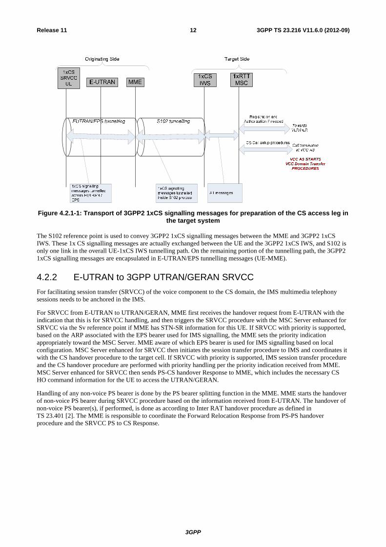
Figure 4.2.1-1: Transport of 3GPP2 1xCS signalling messages for preparation of the CS access leg in the target system
The S102 reference point is used to convey 3GPP2 1xCS signalling messages between the MME and 3GPP2 1xCS IWS. These 1x CS signalling messages are actually exchanged between the UE and the 3GPP2 1xCS IWS, and S102 is only one link in the overall UE-1xCS IWS tunnelling path. On the remaining portion of the tunnelling path, the 3GPP2 1xCS signalling messages are encapsulated in E-UTRAN/EPS tunnelling messages (UE-MME).
4.2.2 E-UTRAN to 3GPP UTRAN/GERAN SRVCC For facilitating session transfer (SRVCC) of the voice component to the CS domain, the IMS multimedia telephony sessions needs to be anchored in the IMS.
For SRVCC from E-UTRAN to UTRAN/GERAN, MME first receives the handover request from E-UTRAN with the indication that this is for SRVCC handling, and then triggers the SRVCC procedure with the MSC Server enhanced for SRVCC via the Sv reference point if MME has STN-SR information for this UE. If SRVCC with priority is supported, based on the ARP associated with the EPS bearer used for IMS signalling, the MME sets the priority indication appropriately toward the MSC Server. MME aware of which EPS bearer is used for IMS signalling based on local configuration. MSC Server enhanced for SRVCC then initiates the session transfer procedure to IMS and coordinates it with the CS handover procedure to the target cell. If SRVCC with priority is supported, IMS session transfer procedure and the CS handover procedure are performed with priority handling per the priority indication received from MME. MSC Server enhanced for SRVCC then sends PS-CS handover Response to MME, which includes the necessary CS HO command information for the UE to access the UTRAN/GERAN.
Handling of any non-voice PS bearer is done by the PS bearer splitting function in the MME. MME starts the handover of non-voice PS bearer during SRVCC procedure based on the information received from E-UTRAN. The handover of non-voice PS bearer(s), if performed, is done as according to Inter RAT handover procedure as defined in TS 23.401 [2]. The MME is responsible to coordinate the Forward Relocation Response from PS-PS handover procedure and the SRVCC PS to CS Response.

3GPP
3GPP TS 23.216 V11.6.0 (2012-09)13Release 11
UE E - UTRAN MME MSC Server Target
UTRAN / GERAN
Measurement Reports
Handover to UTRAN / GERAN required
3 GPP IMS
Initiates SRVCC for voice component
CS handover preparation IMS Service Continuity Procedure
Handles PS - PS HO for non - voice if needed
C S HO response to MME( CS resources )
To eUTRAN Coordinates SRVCC and PS HO response Handover CMD
Handover execution
Figure 4.2.2-1: Overall high level concepts for SRVCC from E-UTRAN to UTRAN/GERAN
4.2.2a E-UTRAN to 3GPP UTRAN vSRVCC For facilitating session transfer of the voice and video components to the CS domain, the IMS multimedia telephony sessions needs to be anchored in the IMS.
For vSRVCC, the UE uses one voice and one video media component over the associated QCI=1 and vSRVCC marked PS bearers for bearer identification reasons. The MME first receives the handover request from E-UTRAN. It then triggers the vSRVCC procedure with the MSC Server enhanced for vSRVCC via the Sv reference point with vSRVCC related information. MSC Server enhanced for vSRVCC then interacts with IMS and initiates the session transfer procedure to IMS and coordinates it with the CS handover procedure to the target cell. If SRVCC with priority is supported, IMS session transfer procedure and the CS handover procedure are performed with priority handling according to the priority indication received from MME.
MSC Server performs SRVCC procedure if the current active session is voice only. MSC Server enhanced for vSRVCC then sends PS-CS Handover Response to MME, which includes the necessary CS HO command information for the UE to access the UTRAN. If the target cell is GERAN, MME only triggers SRVCC (i.e. only the voice component of the Video Call is transferred using the SRVCC procedure).
If SCC AS indicates current active session is voice and video, the MSC Server requests UTRAN radio resources for BS30 bearer and continues with the vSRVCC procedure. The BS30 bearer is a 64 kbps bearer for multimedia as defined in clause 3.1.2.13 of TS 22.002 [38].If the BS30 bearer reservation was unsuccessful, then vSRVCC procedure is considered failed and appropriate rejection cause is given back to E-UTRAN.
Handling of any non QCI=1 and vSRVCC marked PS bearer is done by the PS bearer splitting function in the MME. MME starts the handover of non QCI=1 and vSRVCC marked PS bearer during vSRVCC procedure based on the information received from E-UTRAN. The handover of non QCI=1 and vSRVCC marked PS bearer(s), if performed, is done as according to Inter RAT handover procedure, as defined in TS 23.401 [2]. The MME is responsible to coordinate the Forward Relocation Response from PS-PS handover procedure and the vSRVCC PS to CS Response.
When the UE receives the HO Command indicating a TS 11 or BS30 bearer, it knows whether it should start the CS 3G-324M video codec negotiation or SRVCC.

3GPP
3GPP TS 23.216 V11.6.0 (2012-09)14Release 11
UE E - UTRAN MME MSC Server Target
UTRAN
Measurement Reports
Handover to UTRAN required
3 GPP IMS
Initiates v SRVCC for voice and video component
CS handover preparation IMS Service Continuity Procedure
Handles PS - PS HO for non - voice / video if
needed
P S HO response to MME ( CS resources )
To eUTRAN Coordinates v SRVCC and PS HO response Handover CMD
Handover execution
Interaction with IMS for identifying the media type ( s ) of the session to be transferred due to vSRVCC
Figure 4.2.2a-1: Overall high level concepts for vSRVCC from E-UTRAN to UTRAN
4.2.3 UTRAN (HSPA) to 3GPP UTRAN/GERAN SRVCC For facilitating session transfer (SRVCC) of the voice component to the CS domain, the IMS multimedia telephony sessions needs to be anchored in the IMS.
For SRVCC from UTRAN (HSPA) to UTRAN/GERAN, SGSN first receives the handover request from UTRAN (HSPA) with the indication that this is for SRVCC handling, and then triggers the SRVCC procedure with the MSC Server enhanced for SRVCC via the Sv if SGSN has STN-SR information for this UE. MSC Server enhanced for SRVCC then initiates the session transfer procedure to IMS and coordinates it with the CS handover procedure to the target cell. MSC Server enhanced for SRVCC then sends PS-CS handover Response to SGSN, which includes the necessary CS HO command information for the UE to access the UTRAN/GERAN.
Handling of any non voice PS bearer is done by the PS bearer splitting function in the SGSN. SGSN starts the handover of non voice PS bearer during SRVCC procedure based on the information received from UTRAN (HSPA). The handover of non voice PS bearer(s), if performed, is done as according to Inter/Intra RAT handover procedure as defined in TS 23.060 [10] and TS 25.413 [11]. The SGSN is responsible to coordinate the Forward Relocation Response from PS-PS handover procedure and the SRVCC PS to CS Response.
3GPP
3GPP TS 23.216 V11.6.0 (2012-09)15Release 11
Figure 4.2.3-1: Overall high level concepts for SRVCC from UTRAN (HSPA) to UTRAN/GERAN
4.2.4 SRVCC for IMS emergency sessions
4.2.4.1 E-UTRAN/UTRAN (HSPA) to 3GPP UTRAN/GERAN
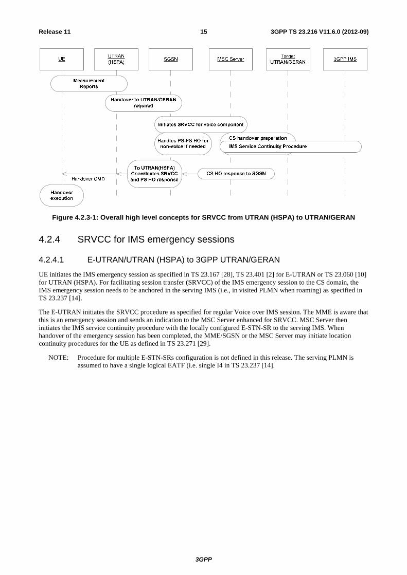
UE initiates the IMS emergency session as specified in TS 23.167 [28], TS 23.401 [2] for E-UTRAN or TS 23.060 [10] for UTRAN (HSPA). For facilitating session transfer (SRVCC) of the IMS emergency session to the CS domain, the IMS emergency session needs to be anchored in the serving IMS (i.e., in visited PLMN when roaming) as specified in TS 23.237 [14].
The E-UTRAN initiates the SRVCC procedure as specified for regular Voice over IMS session. The MME is aware that this is an emergency session and sends an indication to the MSC Server enhanced for SRVCC. MSC Server then initiates the IMS service continuity procedure with the locally configured E-STN-SR to the serving IMS. When handover of the emergency session has been completed, the MME/SGSN or the MSC Server may initiate location continuity procedures for the UE as defined in TS 23.271 [29].
NOTE: Procedure for multiple E-STN-SRs configuration is not defined in this release. The serving PLMN is assumed to have a single logical EATF (i.e. single I4 in TS 23.237 [14].

3GPP
3GPP TS 23.216 V11.6.0 (2012-09)16Release 11
Figure 4.2.4.1-1: Overall high level concepts for SRVCC IMS emergency session with E-STN-SR
4.2.4.2 E-UTRAN to 3GPP2 1xCS
The UE initiates emergency session over E-UTRAN as specified in TS 23.167 [28], TS 23.401 [2], upon detecting handover is required from E-UTRAN to CDMA 1x, the SRVCC emergency procedure apply. To support handover of emergency session the network is aware that the UE and core network support SRVCC and has information to identify Emergency session. When handover of the emergency session has been completed, the MME or the 1xRTT side may initiate location continuity procedures for the UE as defined in TS 23.271 [29].

3GPP
3GPP TS 23.216 V11.6.0 (2012-09)17Release 11
Figure 4.2.4.2-1: E-UTRAN to 3GPP2 1xCS
4.2.4.3 SRVCC in Limited Service Mode
4.2.4.3.1 E-UTRAN/UTRAN (HSPA) to 3GPP UTRAN/GERAN
In order to support SRVCC emergency session domain transfer for UEs in Limited Service Mode (e.g. UICC-less), the MME/SGSN shall support Limited Service Mode UE emergency attach defined in TS 23.401 [2] and TS 23.060 [10] using unauthenticated IMSI or equipment identifier.
When E-UTRAN/UTRAN determines that SRVCC is needed, the MME/SGSN invokes SRVCC procedures to the MSC Server including the UE's equipment identifier. The MSC Server will setup the call leg towards the EATF with the UE's equipment identifier. This procedure is defined in TS 23.237 [14].
4.2.4.3.2 E-UTRAN to 3GPP2 1xCS
In order to support SRVCC emergency session domain transfer for UEs in Limited Service Mode (e.g. UICC-less), the MME shall support Limited Service Mode UE emergency attach defined in TS 23.401 [2] using unauthenticated IMSI or equipment identifier.
When E-UTRAN determines that SRVCC is needed, the MME invokes SRVCC procedures to the 1xCS IWS including the UE's equipment identifier.
3GPP
3GPP TS 23.216 V11.6.0 (2012-09)18Release 11
4.2.5 Void
4.2.6 3GPP UTRAN/GERAN CS to 3GPP E-UTRAN/UTRAN(HSPA) PS SRVCC
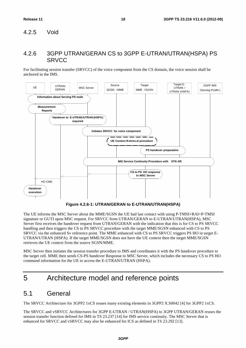
For facilitating session transfer (SRVCC) of the voice component from the CS domain, the voice session shall be anchored in the IMS.
UE
Target
MME / SGSN UTRAN / GERAN
Source
SGSN / MME MSC Server
3 GPP IMS
( Serving PLMN )
Target E - UTRAN /
UTRAN ( HSPA )
Measurement Reports
Handover to E - UTRAN / UTRAN ( HSPA ) required
Initiates SRVCC for voice component
PS handover preparation
IMS Service Continuity Procedure with STN - SR
CS to PS HO response to MSC Server
HO CMD
Handover execution
UE Context R etriev al procedure
Information about Serving PS node
Figure 4.2.6-1: UTRAN/GERAN to E-UTRAN/UTRAN(HSPA)
The UE informs the MSC Server about the MME/SGSN the UE had last contact with using P-TMSI+RAI+P-TMSI signature or GUTI upon MSC request. For SRVCC from UTRAN/GERAN to E-UTRAN/UTRAN(HSPA), MSC Server first receives the handover request from UTRAN/GERAN with the indication that this is for CS to PS SRVCC handling and then triggers the CS to PS SRVCC procedure with the target MME/SGSN enhanced with CS to PS SRVCC via the enhanced Sv reference point. The MME enhanced with CS to PS SRVCC triggers PS HO in target E-UTRAN/UTRAN (HSPA). If the target MME/SGSN does not have the UE context then the target MME/SGSN retrieves the UE context from the source SGSN/MME.
MSC Server then initiates the session transfer procedure to IMS and coordinates it with the PS handover procedure to the target cell. MME then sends CS-PS handover Response to MSC Server, which includes the necessary CS to PS HO command information for the UE to access the E-UTRAN/UTRAN (HSPA).
5 Architecture model and reference points
5.1 General The SRVCC Architecture for 3GPP2 1xCS reuses many existing elements in 3GPP2 X.S0042 [4] for 3GPP2 1xCS.
The SRVCC and vSRVCC Architectures for 3GPP E-UTRAN / UTRAN(HSPA) to 3GPP UTRAN/GERAN reuses the session transfer function defined for IMS in TS 23.237 [14] for IMS service continuity. The MSC Server that is enhanced for SRVCC and vSRVCC may also be enhanced for ICS as defined in TS 23.292 [13].

3GPP
3GPP TS 23.216 V11.6.0 (2012-09)19Release 11
The SRVCC Architecture for 3GPP UTRAN/GERAN CS to 3GPP E-UTRAN / UTRAN(HSPA) reuses the session transfer function defined for IMS in TS 23.237 [14] for IMS service continuity. The MSC Server that is enhanced for CS to PS SRVCC is also enhanced for ICS as defined in TS 23.292 [13].
The overall model and impacts to the various elements is provided in the following clauses.
5.2 Reference architecture
5.2.1 E-UTRAN to 3GPP2 1xCS SRVCC architecture This specification introduces an additional functional entity to those defined in the E-UTRAN architecture TS 23.402 [3], called 1x CS SRVCC interworking solution function (3GPP2 1xCS IWS), see figure 5.2.1-1.
NOTE: The figure only shows the necessary components related to 3GPP2 1xCS IWS.
E-UTRAN
MME
Serving/PDN GW
SGi
1xRTT CS Access
1xRTT MSC
1xCS IWS
S102
S11 S1-MME
S1-U
A1
1xCS SRVCC UE
Bearer before HO
Bearer after HO
SIP signalling
A1
IMS
Tunnelled 1xRTT messages
1xCS SRVCC
UE
Figure 5.2.1-1: SRVCC architecture for E-UTRAN to 3GPP2 1xCS
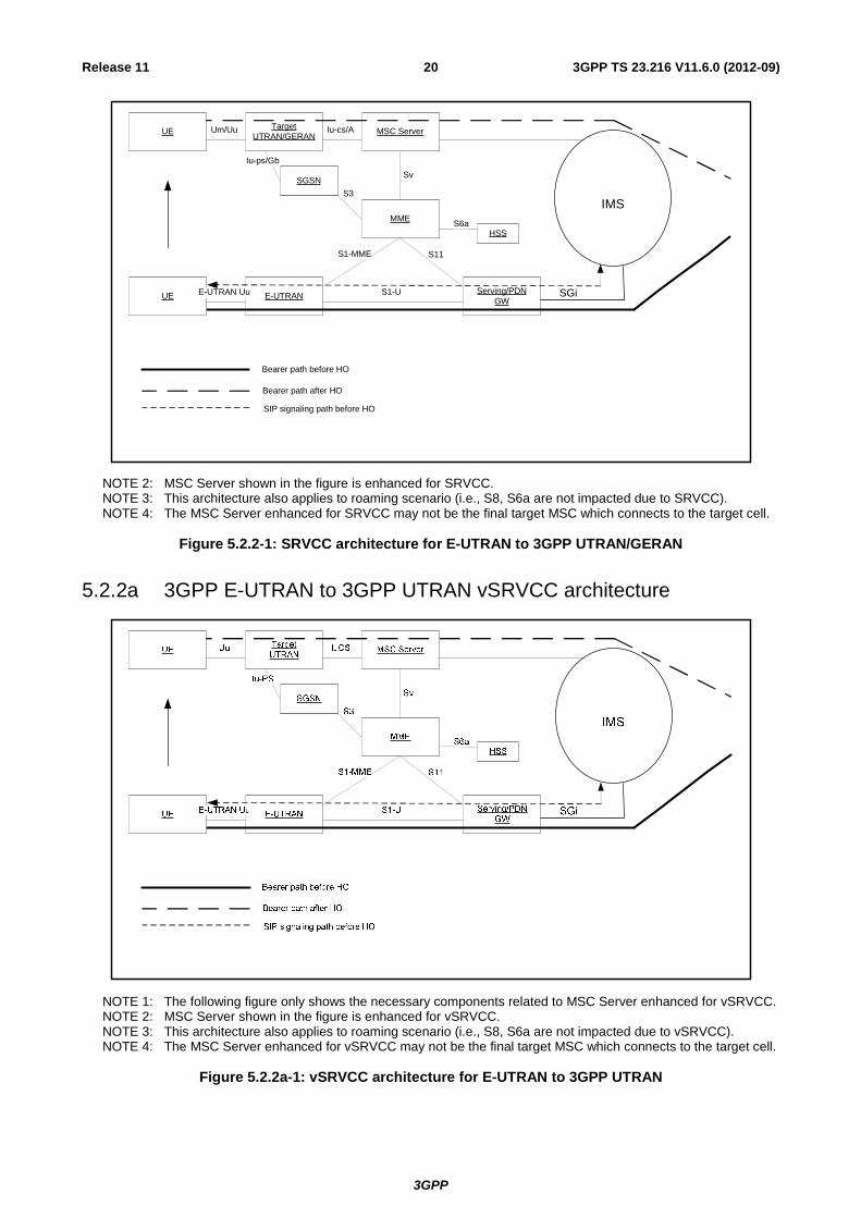
5.2.2 E-UTRAN to 3GPP UTRAN/GERAN SRVCC architecture This specification introduces an additional function to those defined in the E-UTRAN architecture TS 23.401 [2] for SRVCC. This additional function is provided by the MSC Server (i.e., MSC Server enhanced for SRVCC).
NOTE 1: The following figure only shows the necessary components related to MSC Server enhanced for SRVCC.
3GPP
3GPP TS 23.216 V11.6.0 (2012-09)20Release 11
UE EUTRAN
MME
MSC ServerTarget UTRAN/GERAN
Serving/PDNGW
IMS
UE Um/Uu Iucs/A
S3
Sv
S11S1MME
S1UEUTRAN Uu SGi
HSSS6a
SGSN
Iups/Gb
Bearer path before HO
Bearer path after HO
SIP signaling path before HO
NOTE 2: MSC Server shown in the figure is enhanced for SRVCC. NOTE 3: This architecture also applies to roaming scenario (i.e., S8, S6a are not impacted due to SRVCC). NOTE 4: The MSC Server enhanced for SRVCC may not be the final target MSC which connects to the target cell.
Figure 5.2.2-1: SRVCC architecture for E-UTRAN to 3GPP UTRAN/GERAN
5.2.2a 3GPP E-UTRAN to 3GPP UTRAN vSRVCC architecture
NOTE 1: The following figure only shows the necessary components related to MSC Server enhanced for vSRVCC. NOTE 2: MSC Server shown in the figure is enhanced for vSRVCC. NOTE 3: This architecture also applies to roaming scenario (i.e., S8, S6a are not impacted due to vSRVCC). NOTE 4: The MSC Server enhanced for vSRVCC may not be the final target MSC which connects to the target cell.
Figure 5.2.2a-1: vSRVCC architecture for E-UTRAN to 3GPP UTRAN
3GPP
3GPP TS 23.216 V11.6.0 (2012-09)21Release 11
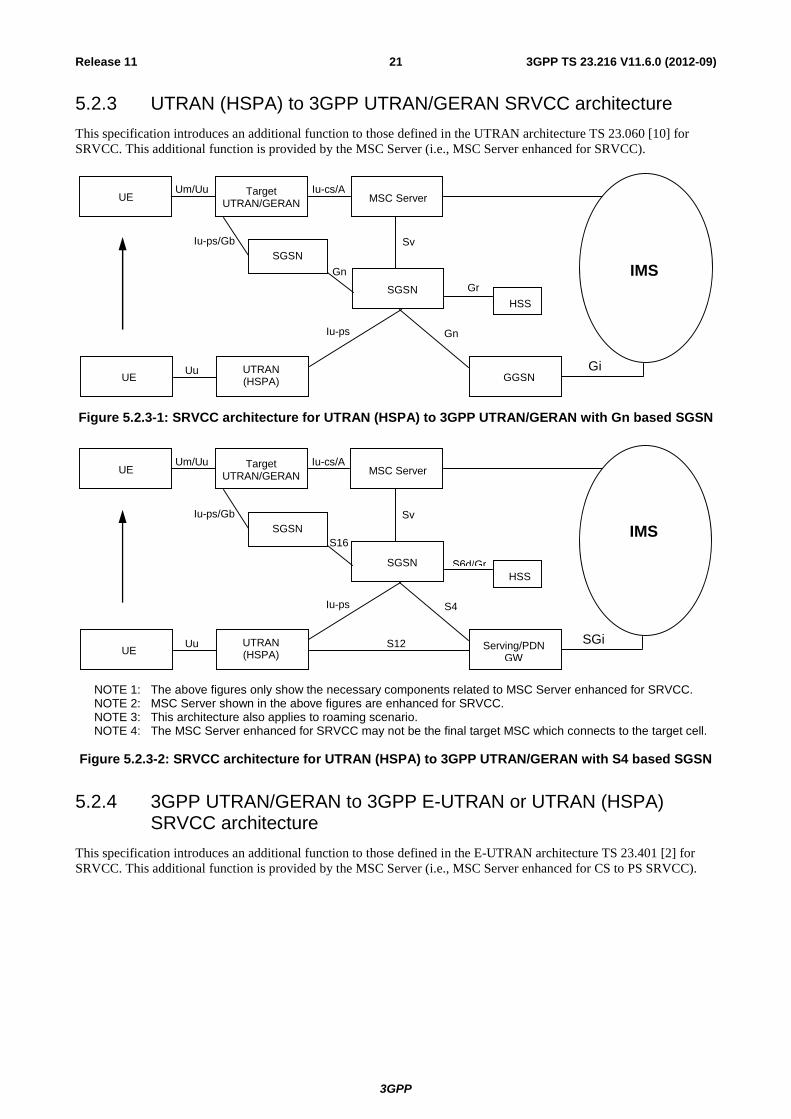
5.2.3 UTRAN (HSPA) to 3GPP UTRAN/GERAN SRVCC architecture This specification introduces an additional function to those defined in the UTRAN architecture TS 23.060 [10] for SRVCC. This additional function is provided by the MSC Server (i.e., MSC Server enhanced for SRVCC).
UE Target
UTRAN/GERAN MSC Server
SGSN
SGSN HSS
GGSN UTRAN (HSPA) UE
IMS
Uu
Um/Uu Iu-cs/A
Iu-ps/Gb
Gn
Sv
Gr
Gn
Gi
Iu-ps
Figure 5.2.3-1: SRVCC architecture for UTRAN (HSPA) to 3GPP UTRAN/GERAN with Gn based SGSN
UE Target
UTRAN/GERAN MSC Server
SGSN
SGSN HSS
Serving/PDN GW
UTRAN (HSPA) UE
IMS
Uu
Um/Uu Iu-cs/A
Iu-ps/Gb
S16
Sv
S6d/Gr
S4
SGi
Iu-ps
S12
NOTE 1: The above figures only show the necessary components related to MSC Server enhanced for SRVCC. NOTE 2: MSC Server shown in the above figures are enhanced for SRVCC. NOTE 3: This architecture also applies to roaming scenario. NOTE 4: The MSC Server enhanced for SRVCC may not be the final target MSC which connects to the target cell.
Figure 5.2.3-2: SRVCC architecture for UTRAN (HSPA) to 3GPP UTRAN/GERAN with S4 based SGSN
5.2.4 3GPP UTRAN/GERAN to 3GPP E-UTRAN or UTRAN (HSPA) SRVCC architecture
This specification introduces an additional function to those defined in the E-UTRAN architecture TS 23.401 [2] for SRVCC. This additional function is provided by the MSC Server (i.e., MSC Server enhanced for CS to PS SRVCC).

3GPP
3GPP TS 23.216 V11.6.0 (2012-09)22Release 11
UE Target E - UTRAN
MME
MSC Server UTRAN / GERAN
Serving / PDN GW
IMS
UE Um / Uu Iu - cs / A
S 3
Sv
S 11 S 1 - MME
S 1 - U E - UTRAN Uu SGi
HSS S 6 a
SGSN
Iu - ps / Gb
Bearer path before HO
Bearer path after HO
SIP signaling path after HO
D
NOTE 1: The above figure only shows the necessary components related to MSC Server enhanced for CS to PS SRVCC.
NOTE 2: MSC Server shown in the figure is enhanced for CS to PS SRVCC. NOTE 3: This architecture also applies to roaming scenario (i.e. S8, S6a are not impacted due to CS to PS
SRVCC).
Figure 5.2.4: CS to PS SRVCC architecture for UTRAN/GERAN to 3GPP E-UTRAN
5.2.5 3GPP UTRAN/GERAN to 3GPP UTRAN (HSPA) SRVCC architecture
This specification introduces an additional function to those defined in the UTRAN architecture TS 23.060 [10] for CS to PS SRVCC. This additional function is provided by the MSC Server (i.e., MSC Server enhanced for CS to PS SRVCC).
UE Target
UTRAN/GERAN MSC Server
SGSN
SGSN HSS
GGSN UTRAN (HSPA) UE
IMS
Uu
Um/Uu Iu-cs/A
Iu-ps/Gb
Gn
Sv
Gr
Gn
Gi
Iu-ps
D
Figure 5.2.5-1: CS to PS SRVCC architecture for 3GPP UTRAN/GERAN to UTRAN (HSPA) with Gn based SGSN

3GPP
3GPP TS 23.216 V11.6.0 (2012-09)23Release 11
UE Target
UTRAN/GERAN MSC Server
SGSN
SGSN HSS
Serving/PDN GW
UTRAN (HSPA) UE
IMS
Uu
Um/Uu Iu-cs/A
Iu-ps/Gb
S16
Sv
S6d
S4
SGi
Iu-ps
S12
D
NOTE 1: The above figures only show the necessary components related to MSC Server enhanced with CS to PS SRVCC.
NOTE 2: MSC Server shown in the above figures are enhanced for CS to PS SRVCC. NOTE 3: This architecture also applies to roaming scenario. Figure 5.2.5-2: CS to PS SRVCC architecture for 3GPP UTRAN/GERAN to UTRAN (HSPA) with S4
based SGSN
5.3 Functional Entities NOTE 1: 3GPP2 components are not described here. Please refer to 3GPP2 X.S0042 [4].
NOTE 2: IMS components are not described here. Please refer to TS 23.237 [14] and TS 23.292 [13].
5.3.1 3GPP2 1x CS SRVCC interworking solution function (1xCS IWS) 3GPP2 1xCS IWS uses the S102 reference point to communicate with the MME and to transport 3GPP2 1xCS signalling messages to the SRVCC UE. The role of the 3GPP2 1xCS IWS is:
- To be a signalling tunnelling end point towards the MME for receiving/sending encapsulated 3GPP2 1xCS signalling messages to/from the UE; and
- To emulate a 1xRTT BSS towards the 1xRTT MSC (reference point A1 as defined in 3GPP2 A.S0014 [20] between 1xBS and MSC).
5.3.2 MSC Server enhanced for E-UTRAN/UTRAN (HSPA) to 3GPP UTRAN/GERAN SRVCC
In addition to the standard MSC Server behavior defined in TS 23.002 [15], an MSC Server which has been enhanced for SRVCC provides the following functions as needed for support of SRVCC:
- Handling the Relocation Preparation procedure requested for the voice component from MME/SGSN and with priority if priority indication is received via the Sv reference point;
- Behaving as MSC Server enhanced for ICS as defined in TS 23.292 [13] if supported and when ICS flag is received via the Sv reference point is set to true and optionally if the MSC Server is configured to know that the VPLMN has a suitable roaming agreement with the HPLMN of the UE;
- Invoking the session transfer procedure or emergency session transfer procedure from IMS to CS as according to TS 23.237 [14] and with priority if priority indication is received via the Sv reference point;
- Coordinating the CS Handover and session transfer procedures;
- Handling the MAP_Update_Location procedure without it being triggered from the UE;

3GPP
3GPP TS 23.216 V11.6.0 (2012-09)24Release 11
- In case of an emergency session, conditionally sending a MAP Subscriber Location Report to a GMLC to support location continuity according to TS 23.271 [29].
5.3.2a MSC Server enhanced for vSRVCC An MSC Server enhanced for SRVCC may be further enhanced for vSRVCC by providing, in addition to the functions specified in clause 5.3.2, the following functions as needed for the support of vSRVCC:
- Initiating the handover towards the target system for BS30 when it receives the Sv request with a vSRVCC indication from the MME and with priority if priority indication is received via the Sv reference point.
- Negotiating with the SCC AS for the last active session to determine if it should perform SRVCC or vSRVCC procedure.
5.3.2b MSC Server enhanced for 3GPP UTRAN/GERAN to E-UTRAN/UTRAN (HSPA) SRVCC
In addition to the standard MSC Server behaviour defined in TS 23.002 [15] and TS 23.292 [13] for MSC Server enhanced for ICS, an MSC Server which has been enhanced for SRVCC from 3GPP UTRAN/GERAN to E-UTRAN/UTRAN (HSPA) provides the following functions as needed:
- The MSC Server informs the RAN about the possibility to perform CS to PS SRVCC by sending a "CS to PS SRVCC operation possible" to the RNC/BSC only for normal TS 11 call. The RAN uses that information for deciding the cells for which the UE reports measurements that lead to handover request to the core network.
- The MSC Server determines the possibility of performing CS to PS SRVCC based on:
- The CS to PS SRVCC capability indication of the UE received from IMS as defined in TS 23.237 [14].
- The presence of the CS to PS SRVCC allowed indication in the subscription data of the user.
- The IMS registration status of the UE.
- The MSC Server informs RAN that CS to PS SRVCC is not possible by sending a "CS to PS SRVCC operation possible" set to "false" to the RNC/BSC on reception of the UE's IMS registration expiration notification from SCC AS during an ongoing CS call.
- The target MME/SGSN selection for supporting CS to PS SRVCC is based on Target ID contained in the HO required and can be performed using the SGSN/MME selection procedures specified in TS 29.303 [37] or using local configuration in the MSC Server.
- The call is a normal TS 11 call (i.e. not an emergency call - TS12, TS 22.003 [39]).
NOTE: The IMS emergency session that is transferred from PS to CS is not subjected for this CS to PS SRVCC procedure.
5.3.3 MME
5.3.3.1 Interworking with 3GPP2 1xCS IWS
5.3.3.1.1 Interworking with 3GPP2 1xCS IWS
If the MME (operator) supports interworking to 3GPP2 1xCS, the MME shall follow the rules and procedures described in TS 23.402 [3] with the following additions and clarifications:
- To be a signalling tunnelling end point towards the 3GPP2 1xCS IWS for sending/receiving encapsulated 3GPP2 1xCS signalling messages to/from the UE, which are encapsulated in S1-MME S1 Information Transfer messages (TS 36.413 [30]).
- release of the E-UTRAN resources after SRVCC to the 3GPP2 1xCS is completed.
- include information to enable 3GPP2 network to determine emergency session.
3GPP
3GPP TS 23.216 V11.6.0 (2012-09)25Release 11
- insert the equipment identifier during the handover procedure for the case UE operating in limited service mode.
5.3.3.1.2 Selection of 3GPP2 1xCS IWS
The 3GPP2 1xCS IWS can be selected based on the local configuration in the MME taking into account the Reference CellID received in the Uplink S1 cdma2000 Tunnelling message.
5.3.3.2 Interworking with 3GPP MSC Server enhanced for SRVCC from E-UTRAN / UTRAN (HSPA) to 3GPP UTRAN/GERAN
5.3.3.2.1 Interworking with 3GPP MSC Server enhanced for (v)SRVCC
If the MME (operator) supports the interworking to 3GPP CS, the MME shall follow the rules and procedures described in TS 23.401 [2] with the following additions and clarifications:
- Performing the PS bearer splitting function by separating the voice PS bearer from the non-voice PS bearers.
- Handling the non-voice PS bearers handover with the target cell as according to Inter RAT handover procedure as defined in TS 23.401 [2].
- Initiating the SRVCC handover procedure for handover of the voice component to the target cell via the Sv interface and including an emergency indication if this is an emergency session. If there are multiple voice bearers and one of those is for IMS emergency session then MME shall only execute the SRVCC for emergency.
NOTE: The UE may have 2 voice PS bearers if both emergency and normal IMS voice sessions are ongoing. Only the PS voice bearer associated with IMS emergency session will be executed for SRVCC.
- Coordinating PS handover and (v)SRVCC handover procedures when both procedures are performed.
- Sending the equipment identifier to the MSC Server during the handover procedure for the case of UEs operating in limited service mode.
- In case of an emergency session, conditionally sending a Subscriber Location Report to a GMLC to support location continuity according to TS 23.271 [29].
- If the MME (operator) supports vSRVCC and if the target is UTRAN, signalling the vSRVCC indication to the source MSC Server and performing bearer splitting of voice and video bearers of the IMS sessions with bi-directional video and voice media e.g. IMS Multimedia Telephony as defined in TS 22.173 [26]..
- If (v)SRVCC with priority is supported and (v)SRVCC is performed for IMS-based MPS session, the MME sets the priority indication appropriately toward the MSC Server enhanced for (v)SRVCC via the Sv reference point.
5.3.3.2.2 PS bearer splitting function
The function identifies the voice PS bearer upon E-UTRAN to UTRAN/GERAN (v)SRVCC and performs different handling of these bearers from the non-voice PS bearers (see detailed procedures in subsequent clauses). For vSRVCC, it also identifies the vSRVCC marked video PS bearer in addition to the voice PS bearer.
5.3.3.2.3 Selection of MSC enhanced for SRVCC
The MSC enhanced for SRVCC can be selected based on DNS procedures (see TS 29.303 [37]) or local configuration in the MME.
5.3.3.3 Interworking of Target MME with 3GPP MSC Server enhanced for SRVCC from 3GPP UTRAN/GERAN to E-UTRAN / UTRAN (HSPA)
If the MME (operator) supports the interworking to 3GPP CS, the target MME shall follow the rules and procedures described in TS 23.401 [2] with the following additions and clarifications:
- Handling the non-voice PS bearers and allocating resources with the target RAN when receiving CS to PS HO request from MSC via the Sv interface.
3GPP
3GPP TS 23.216 V11.6.0 (2012-09)26Release 11
- Selecting the source MME/SGSN based on information about the MME/SGSN provided by the MSC Server using the SGSN/MME selection procedures specified in TS 29.303 [37] or using local configuration in the target MME.
5.3.3A SGSN
5.3.3A.1 Interworking with 3GPP MSC Server enhanced for SRVCC from E-UTRAN / UTRAN (HSPA) to 3GPP UTRAN/GERAN
5.3.3A.1.1 Interworking with 3GPP MSC Server enhanced for SRVCC
If the SGSN (operator) supports the interworking to 3GPP CS, the SGSN shall follow the rules and procedures described in TS 23.060 [10] with the following additions and clarifications:
- Performing the PS bearer splitting function by separating the voice PS bearer from the non-voice PS bearers. VoIP is detected by traffic class=conversational and Source Statistics Descriptor='speech'.
- Handling the non-voice PS bearers handover with the target cell as according to Inter/Intra RAT handover procedure as defined in TS 23.060 [10].
- Initiating the SRVCC handover procedure for handover of the voice component to the target cell via the Sv interface and including an emergency indication if this is an emergency session. If there are multiple voice bearers and one of those is for IMS emergency session then SGSN shall only execute the SRVCC for emergency.
NOTE: The UE may have 2 voice PS bearers if both emergency and normal IMS voice sessions are ongoing. Only the PS voice bearer associated with IMS emergency session will be executed for SRVCC.
- Coordinating PS handover and SRVCC handover procedures when both procedures are performed.
- Sending the equipment identifier to the MSC Server during the handover procedure for the case of UEs operating in limited service mode.
- In case of an emergency session, conditionally sending a MAP Subscriber Location Report to a GMLC to support location continuity according to TS 23.271 [29].
5.3.3A.1.2 PS bearer splitting function
The function identifies the voice PS bearer upon HSPA to UTRAN/GERAN SRVCC and performs different handling on this bearer from the non-voice PS bearers (see detailed procedures in subsequent clauses).
5.3.3A.1.3 Selection of MSC enhanced for SRVCC
The MSC enhanced for SRVCC can be selected based on DNS procedures (see TS 29.303 [37]) or local configuration in the SGSN.
5.3.3A.2 Interworking of Target SGSN with 3GPP MSC Server enhanced for SRVCC from 3GPP UTRAN/GERAN to E-UTRAN / UTRAN (HSPA)
If the SGSN (operator) supports the interworking to 3GPP CS, the target SGSN shall follow the rules and procedures described in TS 23.060 [10] with the following additions and clarifications:
- Handling the non-voice PS bearers and allocating resources with the target RAN when receiving CS to PS HO request from MSC via the Sv interface.
- Selecting the source MME/SGSN based on information about the MME/SGSN provided by the MSC Server using the SGSN/MME selection procedures specified in TS 29.303 [37] or using local configuration in the target SGSN.
3GPP
3GPP TS 23.216 V11.6.0 (2012-09)27Release 11
5.3.4 UE enhanced for SRVCC
5.3.4.1 Interworking with 3GPP2 1xCS
If the UE supports 3GPP2 1xCS access, the 1xCS SRVCC UE is a UE that is capable to perform SRVCC to the 3GPP2 1xCS system. The interaction between UE and E-UTRAN is described in TS 36.300 [16]. The interaction with the 3GPP2 1xCS system is described in this specification.
5.3.4.2 Interworking with 3GPP UTRAN/GERAN for SRVCC from E-UTRAN / UTRAN (HSPA) to 3GPP UTRAN/GERAN
3GPP SRVCC UE is needed to perform SRVCC (see clause 3.1 for 3GPP SRVCC UE definition). The interaction between UE and E-UTRAN is described in TS 36.300 [16] and between UE and UTRAN (HSPA) is described in TS 25.331 [19].
The SRVCC UE indicates to the network that the UE is SRVCC capable when being configured for using IMS speech service supported by the home operator, e.g. the IMS Multimedia Telephony Service for bi-directional speech as described in TS 22.173 [26].
5.3.4.3 Interworking of UE with 3GPP UTRAN/GERAN for SRVCC from 3GPP UTRAN/GERAN to E-UTRAN / UTRAN (HSPA)
The UE supporting CS to PS SRVCC indicates to the network that the UE is CS to PS SRVCC capable when being configured for using IMS speech service supported by the home operator, e.g. the IMS Multimedia Telephony Service for bi-directional speech as described in TS 22.173 [26].
The UE supporting CS to PS SRVCC indicates to the MSC Server the information about the MME / SGSN the UE had last contact with using P-TMSI+RAI+P-TMSI signature or GUTI. This information shall be provided by the UE to the MSC server by NAS signalling upon request from the MSC.
5.3.4a UE enhanced for vSRVCC 3GPP vSRVCC UE signals its vSRVCC capability to the network. If the UE supports vSRVCC capability, it shall also support SRVCC capability.
If needed, the vSRVCC UE initiates the multimedia codec negotiation on the CS domain after the vSRVCC handover is completed.
NOTE: It is recommended that the UE and the network support the MONA codec negotiation mechanism (see TR 26.911 [35] and ITU-T Recommendation H.324 [33], Annex K) to accelerate the call establishment and minimise the interruption time.
5.3.5 Serving/PDN GW No additional requirement due to (v)SRVCC.
NOTE: If SRVCC is deployed and PCC is not used then the PDN GW is not able to enforce the architecture principle to use QCI=1, see clauses 4.1.1 and 4.1.2.
5.3.6 E-UTRAN
5.3.6.1 Interworking with 3GPP2 1xCS
If the E-UTRAN (operator) supports interworking to 3GPP2 1xCS, the E-UTRAN performs the HO trigger, tunnelling of the 3GPP2 1xCS signalling messages toward the MME, and interacting with the SRVCC UE as described in TS 36.300 [16].
E-UTRAN may be capable of determining the neighbour cell list based on the "SRVCC operation possible" indication and/or presence of an established QCI=1 bearer for a specific UE. An example algorithm is provided in clause A.1.
3GPP
3GPP TS 23.216 V11.6.0 (2012-09)28Release 11
NOTE: If E-UTRAN does not update the neighbour cell list dynamically, if E-UTRAN triggers handover to 1x when either the "SRVCC operation possible" indication is set to "false" or there is no established QCI=1 bearer for a specific UE, this will result in an error case.
5.3.6.2 Interworking with 3GPP UTRAN/GERAN for SRVCC from E-UTRAN to 3GPP UTRAN/GERAN
Between UE and E-UTRAN, no additional functionality is required for the E-UTRAN as defined in TS 36.300 [16].
When E-UTRAN selects a target cell for SRVCC handover, it needs to send an indication to MME that this handover procedure requires SRVCC
E-UTRAN may be capable of determining the neighbour cell list based on the "SRVCC operation possible" indication, the UE's Radio Access Capabilities for SRVCC from E-UTRAN to UTRAN/GERAN and PS Voice over UTRAN and/or presence of an established QCI=1 bearer for a specific UE. An example algorithm is provided in clause A.2.
The procedure for E-UTRAN Radio Access Network sharing is described in TS 23.251 [40].
NOTE: In case E-UTRAN does not update the neighbour cell list dynamically, if E-UTRAN triggers handover to a VoIP-incapable cell when the "SRVCC operation possible" indication is set to "false" and there is an established voice (QCI=1) bearer for a specific UE, the establishment of the voice bearer will be rejected by the target access.
5.3.6.2a Interworking with 3GPP UTRAN for vSRVCC
Between UE and E-UTRAN, no additional functionality is required for the E-UTRAN as defined in TS 36.300 [16].
E-UTRAN may be capable of determining the neighbour cell list based on simultaneous presence of established QCI=1 (for voice part) and vSRVCC marked bearers for a specific UE.
NOTE 1 The usage of vSRVCC marked bearer by E-UTRAN is outside the scope of this specification.
NOTE 2: In case E-UTRAN does not update the neighbour cell list dynamically, if E-UTRAN triggers handover to a VoIP incapable cell when the "SRVCC operation possible" indication is set to "false" and there is an established voice (QCI=1) bearer for a specific UE, the establishment of the voice and video bearers will be rejected by the target access.
5.3.6A UTRAN (HSPA) When HSPA capable UTRAN selects a target cell for SRVCC handover, it needs to send an indication to SGSN that this handover procedure requires SRVCC.
NOTE 1: UTRAN (HSPA) assumes that SGSN supports SRVCC functionality.
UTRAN may be capable of determining the neighbour cell list based on the "SRVCC operation possible" indication, the UE's Radio Access Capabilities for SRVCC from UTRAN (HSPA) to UTRAN/GERAN and/or presence of an established voice bearer (i.e. bearer with Traffic Class = Conversational and Source Statistic Descriptor = 'speech') for a specific UE. An example algorithm is provided in clause A.3.
The procedure for UTRAN Radio Access Network sharing is described in TS 23.251 [40].
NOTE 2: In case UTRAN does not update the neighbour cell list dynamically, if UTRAN triggers handover to a VoIP-incapable cell when the "SRVCC operation possible" indication is set to "false" and there is an established bearer with Traffic Class = Conversational and Source Statistic Descriptor = 'speech' for a specific UE, the establishment of the voice bearer will be rejected by the target access.
5.3.6B GERAN/UTRAN CS When GERAN/UTRAN selects a target cell for CS to PS SRVCC handover, it shall send an indication to MSC Server enhanced for CS to PS SRVCC that this handover procedure requires CS to PS SRVCC.

3GPP
3GPP TS 23.216 V11.6.0 (2012-09)29Release 11
GERAN/UTRAN may be capable of determining the neighbour cell list based on the "CS to PS SRVCC operation possible" indication received from MSC Server enhanced for CS to PS SRVCC, the UE's Radio Access Capabilities for CS to PS SRVCC over GERAN/UTRAN, and the existence of CS voice call. An example algorithm is provided in Annex A, clause A.4.
5.3.7 HSS
5.3.7.1 Interworking with 3GPP UTRAN/GERAN for SRVCC or vSRVCC from E-UTRAN / UTRAN (HSPA) to 3GPP UTRAN/GERAN
The STN-SR, vSRVCC flag, C-MSISDN and optional ICS flag per VPLMN, for the subscriber are downloaded to MME from HSS during E-UTRAN attach procedure. For UTRAN (HSPA), these subscription information are downloaded to SGSN from HSS during GPRS attach procedure. HSS also informs the MME/SGSN when STN-SR is modified or removed from the subscription.
The ICS flag is used by the MSC Server enhanced for (v)SRVCC to behave also as MSC Server enhanced for ICS in TS 23.292 [13] if supported by the network.
NOTE: HSS functionality is not impacted when MSC Server enhanced for (v)SRVCC performs the MAP_Update_Location procedure.
5.3.7.2 Interworking with 3GPP UTRAN/GERAN for SRVCC from 3GPP UTRAN/GERAN to E-UTRAN / UTRAN (HSPA)
The "CS to PS SRVCC allowed" indication and optional ICS flag are downloaded to MSC Server from HSS during attach procedure.
5.3.8 PCC The PCRF enforces the architecture principle to use QCI=1 (and traffic-class conversational with source statistics descriptor ="speech") for voice bearer with IMS sessions anchored in the SCC AS, based on the service the session relates to. This may be achieved by deploying S9 reference point, or configuration and roaming agreements.
The PCEF should enforce to multiplex the media streams from multiple concurrent normal voice sessions.
NOTE: In this Release the UE initiated PDP context for voice bearer is not supported.
For vSRVCC, the PCRF enforces that the video bearer of IMS sessions anchored in the SCC AS, is marked with the "PS to CS session continuity indicator", see TS 23.203 [32], and hence can be identified as vSRVCC marked video PS bearer in clause 5.3.3.2.2.
5.4 Reference points
5.4.1 MME – 3GPP2 1xCS IWS (S102) The S102 reference point provides a tunnel between MME and 3GPP2 1xCS IWS to relay 3GPP2 1xCS signalling messages. 1x CS signalling messages are those messages that are defined for A21 interface as described in 3GPP2 A.S0008-C [8].
NOTE. It is up to stage 3 to determine whether the tunnelling protocol for S102 can be defined as exactly as in A21. If so, S102 is then equivalent to A21.
5.4.2 MME/SGSN – MSC Server (Sv) The Sv reference point provides (v)SRVCC support from 3GPP E-UTRAN/UTRAN (HSPA) to 3GPP UTRAN/GERAN.
MME/SGSN includes the optional ICS flag if received from the HSS.

3GPP
3GPP TS 23.216 V11.6.0 (2012-09)30Release 11
If (v)SRVCC with priority is supported, MME includes the priority indication if the SRVCC is for IMS-based MPS session.
The Sv reference point provides additionally SRVCC support from 3GPP UTRAN/GERAN to 3GPP E-UTRAN/UTRAN (HSPA).
5.4.3 E-UTRAN – MME (S1-MME) For 3GPP2 1xCS SRVCC, the S1-MME reference point provides S1 Information Transfer message (TS 36.413 [30]) between UE and MME to relay the 3GPP2 1xCS signalling messages.
For 3GPP (v)SRVCC, the S1-MME reference point allows handover signalling between E-UTRAN and MME. It is defined in TS 36.300 [16]
5.4.3A UTRAN (HSPA) – SGSN (Iu-ps) For 3GPP HSPA SRVCC, the Iu-ps reference point allows handover signalling between UTRAN and SGSN. It is defined in TS 25.413 [11].
5.4.4 HSS – MME (S6a) For 3GPP (v)SRVCC, the S6a is used to download SRVCC related information to MME during E-UTRAN attach procedure or to inform MME that STN-SR information in the HSS has changed.
For 3GPP vSRVCC, the S6a is used to download vSRVCC flag to MME during E-UTRAN attach procedure or to inform MME that vSRVCC flag in the HSS has changed.
5.4.5 HSS – SGSN (Gr, S6d) For 3GPP SRVCC, either the Gr or the S6d is used to download SRVCC related information to SGSN during UTRAN (HSPA) attach procedure or to inform SGSN that STN-SR information in the HSS has changed.
5.4.6 HSS - MSC (MAP D) If the subscriber is allowed to have CS to PS SRVCC, the HSS shall include the "CS to PS SRVCC allowed" indication in the Insert Subscriber Data sent to the MSC Server. The "CS to PS SRVCC allowed" indication may be specific for each VPLMN.
6 Procedures and flows
6.1 SRVCC from E-UTRAN to 3GPP2 1xCS
6.1.1 E-UTRAN Attach procedure for SRVCC E-UTRAN attach or emergency attach procedure for 3GPP2 SRVCC UE is performed as defined in TS 23.401 [2] with the following additions:
- SRVCC UE includes the SRVCC capability indication as part of the "UE Network Capability" in the Attach Request message. MME stores this information for SRVCC operation.
- SRVCC UE capable for IMS emergency calls shall include the SRVCC capability indication as part of the UE network capability in the Emergency Attach Request message. MME stores this information for emergency SRVCC operation.
- MME includes a "SRVCC operation possible" indication in the S1 AP Initial Context Setup Request, meaning that both UE and MME are SRVCC-capable.

3GPP
3GPP TS 23.216 V11.6.0 (2012-09)31Release 11
6.1.2 Service Request procedures for SRVCC Service Request procedures for 3GPP2 SRVCC UE are performed as defined in TS 23.401 [2] with the following additions:
- MME includes a "SRVCC operation possible" indication in the S1 AP Initial Context Setup Request, meaning that both UE and MME are SRVCC-capable.
6.1.2A PS Handover procedures for SRVCC Intra-E-UTRAN S1-based handover procedures for 3GPP2 SRVCC UE are performed as defined in TS 23.401 [2] with the following additions:
- The target MME includes a "SRVCC operation possible" indication in the S1-AP Handover Request message, meaning that both UE and the target MME are SRVCC-capable.
For X2-based handover, the source eNodeB includes a "SRVCC operation possible" indication in the X2-AP Handover Request message to the target eNodeB as specified in TS 36.423 [36].
6.1.3 Call flows for SRVCC from E-UTRAN Figure 6.1.3-1 illustrates a high-level call flow for the E-UTRAN-to-1x voice service continuity procedure.
Figure 6.1.3-1: LTE VoIP-to-1x CS voice service continuity
1. Ongoing VoIP session over the IMS access leg established over EPS/E-UTRAN access.
3GPP
3GPP TS 23.216 V11.6.0 (2012-09)32Release 11
2. 1xCS SRVCC UE sends measurement reports to eNodeB.
3. The E-UTRAN (e.g., based on some trigger, measurement reports) makes a determination to initiate an inter-technology handover to cdma2000 1xRTT.
4. The E-UTRAN signals the UE to perform an inter-technology handover by sending a Handover from EUTRA Preparation Request (3G1x Overhead Parameters, RAND value) message.
5. The UE initiates signalling for establishment of the CS access leg by sending a UL handover preparation Transfer message containing the 1xRTT Origination message. For the case of emergency voice service continuity, the request includes a Request-Type = "emergency handover" and the MEID (e.g. IMEI) is included.
6. The E-UTRAN sends an Uplink S1 cdma2000 Tunnelling (MEID, RAND, 1x Origination, Reference CellID) message to the MME. The eNodeB will also include CDMA2000 HO Required Indication IE to Uplink S1 CDMA2000 Tunnelling message, which indicates to the MME that the handover preparation has started.
7. Upon reception of the Uplink S1 cdma2000 Tunnelling message, the MME selects a 3GPP2 1xCS IWS as specified in clause 5.3.3.1.2 and encapsulates the 1x Origination Message along with the MEID and RAND in a S102 Direct Transfer message (as "1x Air Interface Signalling").
8. The traffic channel resources are established in the 1x RTT system and 3GPP2 1xCS procedures for initiation of Session Transfer are performed as per 3GPP2 X.S0042 [4].
NOTE 1: Step 9 and 3GPP2 1xCS procedures in step 8 are independent of each other.
NOTE 2: For non-emergency session transfers, the "VDN" parameter referred to in 3GPP2 X.S0042 [4] corresponds to the STN-SR parameter defined in TS 23.237 [14].
NOTE 3: The emergency session transfer procedures and procedures for the 1x CS SRVCC UE obtaining the local emergency STN-SR will be specified by 3GPP2.
9. The 3GPP2 1xCS IWS creates a 1x message and encapsulates it in a S102 Direct Transfer message (1x message, Handover indicator). If the 3GPP2 access was able to allocate resources successfully, the 1x message is a 1x Handover Direction message and the handover indicator indicates successful resource allocation. Otherwise, the handover indicator indicates to the MME that handover preparation failed and the embedded 1x message indicates the failure to the UE.
10. The MME sends the 1x message and CDMA2000 HO Status IE in a Downlink S1 cdma2000 Tunnelling message to the E-UTRAN. The CDMA2000 HO Status IE is set according to the handover indicator received over the S102 tunnel.
11. If the CDMA2000 HO Status IE indicates successful handover preparation, the E-UTRAN forwards the 1x Handoff Direction message embedded in a Mobility from EUTRA Command message to the UE. This is perceived by the UE as a Handover Command message. If handover preparation failed, DL Information transfer message will be sent instead, with the embedded 1xRTT message that indicates the failure to the UE.
12. Once the UE receives the traffic channel information from the cdma2000 1xRTT system, the UE retunes to the 1xRTT radio access network and performs traffic channel acquisition with the 1xRTT CS access (e.g., 1xRTT BSS).
13. The UE sends a 1xRTT handoff completion message to the 1xRTT CS access (e.g., 1xRTT BSS).
14. The 1xRTT CS Access sends message to 1xRTT MSC to indicate of handoff done. The resources between 1x CS IWS and 1xRTT MSC may be released at this step.
15. Ongoing voice call over the CS access leg established over 1xRTT access. The E-UTRAN/EPS context may be released based on the normal E-UTRAN/EPS procedure.
16. The eNodeB sends an S1 UE Context Release Request (Cause) message to the MME. Cause indicates the S1 release procedure is caused by handover from E-UTRAN to 1xRTT.
17. The MME deactivates GBR bearers towards S-GW and P-GW(s) by initiating MME-initiated Dedicated Bearer Deactivation procedure as specified in TS 23.401 [2]. The MME starts preservation and suspension of non-GBR bearers by sending Suspend Notification message towards S-GW. The S-GW releases S1-U bearers for the UE and sends Suspend Notification message to the P-GW(s). The MME stores in the UE context that the UE is in

3GPP
3GPP TS 23.216 V11.6.0 (2012-09)33Release 11
suspended status. All the preserved non-GBR bearers are marked as suspended status in the S-GW and P-GW. The P-GW should discard packets if received for the suspended UE.
18. S1 UE Context in the eNodeB is released as specified in TS 23.401 [2].
19. For an emergency services session after handover is complete, if the control plane location solution is used on the source side, the source MME shall send a Subscriber Location Report carrying an indication of the 1xRTT MSC (e.g. reference cell ID) to the GMLC associated with the source side as defined in TS 23.271 [29] to support location continuity. This enables location continuity for the 1xRTT side. Alternatively, if the control plane solution is not used on the source side, location continuity procedures shall be instigated on the 1xRTT side.
NOTE 4: Location continuity on the 1xRTT side will be specified by 3GPP2.
If the UE has returned to E-UTRAN after the CS voice call was terminated, then the UE shall resume PS service by sending TAU to MME. The MME will in addition inform S-GW and P-GW(s) to resume the suspended bearers. Resuming the suspended bearers in the S-GW and in the P-GW should be done by implicit resume using the Modify Bearer Request message if it is triggered by the procedure in operation, e.g. TAU or Service Request. The S-GW is aware of the suspend state of the bearers and will forward the Modify Bearer Request to the P-GW. Explicit resume using the Resume Notification message should be used in cases when Modify Bearer Request is not triggered by the procedure in operation.
6.2 E-UTRAN and 3GPP GERAN/UTRAN (v)SRVCC
6.2.1 E-UTRAN Attach procedure for (v)SRVCC E-UTRAN attach procedure for 3GPP (v)SRVCC UE is performed as defined in TS 23.401 [2] with the following additions:
- (v)SRVCC UE includes the (v)SRVCC capability indication as part of the "MS Network Capability" in the Attach Request message and in Tracking Area Updates. MME stores this information for (v)SRVCC operation. The procedures are as specified in TS 23.401 [2].
NOTE 1: If the service configuration on the UE is changed (e.g. the user changes between an IMS speech/video service supported by the home operator and a PS speech service incompatible with (v)SRVCC), the UE can change its (v)SRVCC capability indication as part of the "MS Network Capability" in a Tracking Area Update message.
- SRVCC UE includes the GERAN MS Classmark 3 (if GERAN access is supported), MS Classmark 2 (if GERAN or UTRAN access or both are supported) and Supported Codecs IE (if GERAN or UTRAN access or both are supported) in the Attach Request message and in the non-periodic Tracking Area Update messages.
NOTE 2: MS Classmark 2, MS Classmark 3, STN-SR, C-MSISDN, ICS Indicator and the Supported Codec IE are not sent from the source MME to the target MME/SGSN at inter CN-node idle mode mobility.
- HSS includes STN-SR and C-MSISDN as part of the subscription data sent to the MME. If the STN-SR is present, it indicates the UE is SRVCC subscribed. If a roaming subscriber is determined by the HPLMN not allowed to have SRVCC in the VPLMN then HSS does not include STN-SR and C-MSISDN as part of the subscription data sent to the MME. If the subscriber is allowed to have vSRVCC in the VPLMN then HSS also includes vSRVCC flag as part of the subscription data sent to the MME.
- MME includes a "SRVCC operation possible" indication in the S1 AP Initial Context Setup Request, meaning that both UE and MME are SRVCC-capable.
E-UTRAN emergency attach procedure for 3GPP SRVCC UE is performed as defined in TS 23.401 [2] and above with the following clarifications:
- SRVCC UE shall include the SRVCC capability indication as part of the "MS Network Capability" in the Emergency Attach Request message, and maintained during Tracking Area Updates. MME stores this information for SRVCC operation. The procedures are as specified in TS 23.401 [2].

3GPP
3GPP TS 23.216 V11.6.0 (2012-09)34Release 11
6.2.1A Service Request procedures for (v)SRVCC Service Request procedures for 3GPP (v)SRVCC UE are performed as defined in TS 23.401 [2] with the following additions:
- MME includes a "SRVCC operation possible" indication in the S1 AP Initial Context Setup Request, meaning that both UE and MME are SRVCC-capable.
6.2.1B PS Handover procedures for (v)SRVCC Intra-E-UTRAN S1-based handover and E-UTRAN to UTRAN (HSPA) Iu mode Inter RAT handover procedures for 3GPP SRVCC UE are performed as defined in TS 23.401 [2] with the following additions:
- MS Classmark 2, MS Classmark 3, STN-SR, C-MSISDN, ICS Indicator and the Supported Codec IE shall be sent from the source MME to the target MME/SGSN if available.
- The target MME includes a "SRVCC operation possible" indication in the S1-AP Handover Request message, meaning that both UE and the target MME are SRVCC-capable.
- The target SGSN includes a "SRVCC operation possible" indication in the RANAP Common ID message, meaning that both UE and the target SGSN are SRVCC-capable.
For X2-based handover, the source eNodeB includes a "SRVCC operation possible" indication in the X2-AP Handover Request message to the target eNodeB as specified in TS 36.423 [36].
6.2.1C Dedicated Bearer Establishment and Modification procedures for vSRVCC
Dedicated Bearer Establishment and Modification procedures for a session for which vSRVCC is allowed are performed as defined in TS 23.401 [2] with the following additions:
- If dynamic PCC is deployed, the PCRF in the serving PLMN (i.e., VPLMN if roaming) interacts with the P-GW or S-GW as defined in TS 23.203 [32]. The P-GW and S-GW include a "vSRVCC indicator" in Create Bearer Request or Update Bearer Request messages that the bearer has been allocated for video media.
6.2.2 Call flows for (v)SRVCC from E-UTRAN NOTE 1: If the MSC Server enhanced for (v)SRVCC controls the target BSS/RNS, the steps depicted with dot-
dashed arrows representing the MSC-MSC handover procedure defined in TS 23.009 [18] are not executed and the functions of the MSC Server enhanced for (v)SRVCC are merged with those of the target MSC.
NOTE 2: For the sake of brevity the call flow descriptions use "MSC Server" instead of "MSC Server enhanced for (v)SRVCC".
NOTE 3: The target MSC need not be enhanced for (v)SRVCC.
6.2.2.1 SRVCC from E-UTRAN to GERAN without DTM support
Depicted in figure 6.2.2.1-1 is a call flow for SRVCC from E-UTRAN to GERAN without DTM support. The flow requires that eNB can determine that the target is GERAN without DTM support or that the UE is without DTM support.

3GPP
3GPP TS 23.216 V11.6.0 (2012-09)35Release 11
UE Source E-UTRAN
Source MME
MSC Server/ MGW
Target MSC
14. Handover Command
Target BSS
1. Measurement reports
3. Handover Required
S-GW / PDN GW
2. Decision for HO
5.PS to CS Req 6.Prep HO Req
7. HO Request/Ack
8.Prep HO Resp
9. Establish circuit
19. HO Complete
20.SES (HO Complete)
21. ANSWER
13.PS to CS Resp
15. HO from EUTRAN command
HSS/ HLR
23b.UpdateLoc
10. Initiation of Session Transfer (STN-SR or E-STN-SR)
11. Session transfer and Update remote end
IMS
12. Release of IMS access leg
22. PS to CS Complete/Ack
Target SGSN
16. UE tunes to GERAN
17. HO Detection 18. Suspend (see TS 23.060)
18. Suspend 18. Suspend Request / Response
22a. Bearer handling and suspension
4. Bearer Splitting
GMLC 24. Subscriber Location Report
23a. TMSI Reallocation
22b. Release Resources
Figure 6.2.2.1-1: SRVCC from E-UTRAN to GERAN without DTM support
1. UE sends measurement reports to E-UTRAN.
2. Based on UE measurement reports the source E-UTRAN decides to trigger an SRVCC handover to GERAN.
3. Source E-UTRAN sends Handover Required (Target ID, generic Source to Target Transparent Container, SRVCC HO Indication) message to the source MME. The E-UTRAN places the "old BSS to new BSS information IE" for the CS domain in the generic Source to Target Transparent Container. The SRVCC HO indication indicates to the MME that target is only CS capable, hence this is a SRVCC handover operation only towards the CS domain. The message includes an indication that the UE is not available for the PS service in the target cell.
4. Based on the QCI associated with the voice bearer (QCI 1) and the SRVCC HO indication, the source MME splits the voice bearer from the non voice bearers and initiates the PS-CS handover procedure for the voice bearer only towards MSC Server.
5. The MME sends a SRVCC PS to CS Request (IMSI, Target ID, STN-SR, C-MSISDN, generic Source to Target Transparent Container, MM Context, Emergency Indication) message to the MSC Server. If SRVCC with priority is supported, the MME also includes priority indication in SRVCC PS to CS Request if it detects the SRVCC requires priority handling. The detection is based on the ARP associated with the EPS bearer used for IMS signalling. The priority indication corresponds to the ARP information element. The Emergency Indication

3GPP
3GPP TS 23.216 V11.6.0 (2012-09)36Release 11
and the equipment identifier are included if the ongoing session is emergency session. Authenticated IMSI and C-MSISDN shall also be included, if available. The MME received STN-SR and C-MSISDN from the HSS as part of the subscription profile downloaded during the E-UTRAN attach procedure. The MM Context contains security related information. CS security key is derived by the MME from the E-UTRAN/EPS domain key as defined in TS 33.401 [22]. The CS Security key is sent in the MM Context.
6. The MSC Server interworks the PS-CS handover request with a CS inter-MSC handover request by sending a Prepare Handover Request message to the target MSC. If SRVCC with priority is supported, and the MSC Server receives the priority indication (i.e. ARP) in the SRVCC PS to CS Request, the MSC server/MGW sends Prepare Handover Request message to the Target MSC with priority indication mapped from the ARP. The MSC Server maps the ARP to the priority level, pre-emption capability/vulnerability for CS services based on local regulation or operator settings. The priority indication indicates the CS call priority during handover as specified in TS 48.008 [23] for GSM/EDGE. The MSC Server assigns a default SAI as Source ID on the interface to the target BSS and uses BSSMAP encapsulated for the Prepare Handover Request.
NOTE 1: The value of the default SAI is configured in the MSC and allows a release 8 and later BSC to identify that the source for the SRVCC Handover is E-UTRAN. To ensure correct statistics in the target BSS the default SAI should be different from the SAIs used in UTRAN.
7. Target MSC performs resource allocation with the target BSS by exchanging Handover Request/ Acknowledge messages. If the MSC Server indicated priority, the target BSS allocates the radio resource based on the existing procedures with priority indication, as specified in TS 23.009 [18] and in TS 48.008 [23] for GSM/EDGE.
8. Target MSC sends a Prepare Handover Response message to the MSC Server.
9. Establishment of circuit connection between the target MSC and the MGW associated with the MSC Server e.g. using ISUP IAM and ACM messages.
10. For non-emergency session, the MSC Server initiates the Session Transfer by using the STN-SR e.g. by sending an ISUP IAM (STN-SR) message towards the IMS. If this is a priority session, the MSC Server includes priority indication to the IMS and the IMS entity handles the session transfer procedure with priority. The priority indication in the Session Transfer is mapped by the MSC Server from the priority indication (i.e. ARP) in the SRVCC PS to CS Request received in step 5. The mapping of the priority level is based on operator policy and/or local configuration, and the IMS priority indicator should be the same as for the original IMS created over PS. For emergency session, the MSC Server initiates the Session Transfer by using the locally configured E-STN-SR and by including the equipment identifier. IMS Service Continuity or Emergency IMS Service Continuity procedures are applied for execution of the Session Transfer, see TS 23.237 [14].
NOTE 2: This step can be started after step 8.
NOTE 3: If the MSC Server is using an ISUP interface, then the initiation of the session transfer for non-emergency session may fail if the subscriber profile including CAMEL triggers is not available prior handover (see clause 7.3.2.1.3 in TS 23.292 [13]), and can also fail if CAMEL triggers are available and local anchor transfer function is used (see TS 23.237 [14]). If the subscriber profile is available prior handover then CAMEL triggers others than those used in clause 7.3.2.1.3 of TS 23.292 [13] are not used during the transfer.
11. During the execution of the Session Transfer procedure the remote end is updated with the SDP of the CS access leg. The downlink flow of VoIP packets is switched towards the CS access leg at this point.
12. Source IMS access leg is released as per TS 23.237 [14].
NOTE 4: Steps 11 and 12 are independent of step 13.
13. MSC Server sends a SRVCC PS to CS Response (Target to Source Transparent Container) message to the source MME.
14. Source MME sends a Handover Command (Target to Source Transparent Container) message to the source E-UTRAN. The message includes information about the voice component only.
15. Source E-UTRAN sends a Handover from E-UTRAN Command message to the UE.
16. UE tunes to GERAN.

3GPP
3GPP TS 23.216 V11.6.0 (2012-09)37Release 11
17. Handover Detection at the target BSS occurs. The UE sends a Handover Complete message via the target BSS to the target MSC. If the target MSC is not the MSC Server, then the Target MSC sends an SES (Handover Complete) message to the MSC Server.
18. The UE starts the Suspend procedure specified in TS 23.060 [10], clause 16.2.1.1.2. The TLLI and RAI pair are derived from the GUTI as described in TS 23.003 [27]. This triggers the Target SGSN to send a Suspend Notification message to the Source MME. The MME returns a Suspend Acknowledge to the Target SGSN.
NOTE 5: This step may take place in parallel with steps 19-22.
NOTE 6: The MME might not be able to derive the GUTI from the received P-TMSI and RAI pair and therefore it might not be able to identify which UE context is associated with the Suspend Notification message. Also in this case the bearers are deactivated and/or suspended as in step 22a.
19. Target BSS sends a Handover Complete message to the target MSC.
NOTE 7: This step may take place immediately after Handover Detection at the target BSS occurs in step 17, before the BSS has received a Suspend message from the UE.
20. Target MSC sends an SES (Handover Complete) message to the MSC Server. The speech circuit is through connected in the MSC Server/MGW according to TS 23.009 [18].
21. Completion of the establishment procedure with ISUP Answer message to the MSC Server according to TS 23.009 [18].
22. MSC Server sends a SRVCC PS to CS Complete Notification message to the source MME, informing it that the UE has arrived on the target side. Source MME acknowledges the information by sending a SRVCC PS to CS Complete Acknowledge message to the MSC Server.
22a. The MME deactivates bearers used for voice and other GBR bearers. All GBR bearers are deactivated towards S-GW and P-GW by initiating MME-initiated Dedicated Bearer Deactivation procedure as specified in TS 23.401 [2]. PS-to-CS handover indicator is notified to P-GW for voice bearer during the bearer deactivation procedure. For GTP-based S5/S8, the S-GW requests the P-GW to delete all GBR bearer contexts by sending a Delete Bearer Command message. If dynamic PCC is deployed, the P-GW may interact with PCRF as defined in TS 23.203 [32]. For PMIP-based S5/S8, S-GW interacts with the PCRF which in turn updates PCC rules for GBR traffic in the P-GW.
The MME starts preservation and suspension of non-GBR bearers by sending Suspend Notification message towards S-GW. For these non-GBR bearers, the S-GW releases S1-U bearers for the UE and sends Suspend Notification message to the P-GW(s). The MME stores in the UE context that UE is in suspended status. All the preserved non-GBR bearers are marked as suspended status in the S-GW and P-GW. The P-GW should discard packets if received for the suspended UE.
22b. The source MME requests the release of the resources, including release of the S1 signalling connection, to the Source eNodeB. The Source eNodeB releases its resources related to the UE and responds back to the MME.
23a. If the HLR is to be updated, i.e. if the IMSI is authenticated but unknown in the VLR, the MSC Server performs a TMSI reallocation towards the UE using its own non-broadcast LAI and, if the MSC Server and other MSC/VLRs serve the same (target) LAI, with its own Network Resource Identifier (NRI).
NOTE 8: The TMSI reallocation is performed by the MSC Server towards the UE via target MSC.
23b. If the MSC Server performed a TMSI reallocation in step 23a, and if this TMSI reallocation was completed successfully, the MSC Server performs a MAP Update Location to the HSS/HLR.
NOTE 9: This Update Location is not initiated by the UE.
24. For an emergency services session after handover is complete, the source MME or the MSC Server may send a Subscriber Location Report carrying the identity of the MSC Server to a GMLC associated with the source or target side, respectively, as defined in TS 23.271 [29] to support location continuity.
NOTE 10: Any configuration of the choice between a source MME versus MSC Server update to a GMLC needs to ensure that a single update occurs from one of these entities when the control plane location solution is used on the source and/or target sides.

3GPP
3GPP TS 23.216 V11.6.0 (2012-09)38Release 11
After the CS voice call is terminated and if the UE is still in GERAN (or for any other reason specified in TS 24.008), then the UE shall resume PS services as specified in TS 23.060 [10]. A Gn SGSN will follow TS 23.060 [10] to resume the PDP Context(s). An S4-SGSN will follow TS 23.060 [10] to resume the bearers, and will in addition inform S-GW and P-GW(s) to resume the suspended bearers. If the UE has returned to E-UTRAN after the CS voice call was terminated, then the UE shall resume PS service by sending TAU to MME. The MME will in addition inform S-GW and P-GW(s) to resume the suspended bearers. Resuming the suspended bearers in the S-GW and in the P-GW should be done by implicit resume using the Modify Bearer request message if it is triggered by the procedure in operation, e.g. RAU, TAU or Service Request. The S-GW is aware of the suspend state of the bearers and will forward the Modify Bearer request to the P-GW. Explicit resume using the Resume Notification message should be used in cases when Modify Bearer Request is not triggered by the procedure in operation.
6.2.2.1A SRVCC from E-UTRAN to GERAN with DTM but without DTM HO support and from E-UTRAN to UTRAN without PS HO
The call flow for this scenario is similar to the call flow depicted in figure 6.2.2.1-1, with the exceptions that the Suspend procedure (step 18 and step 22a in figure 6.2.2.1-1) is not performed and that the MME only deactivates bearers used for voice (step 22a in figure 6.2.2.1-1) and sets the PS-to-CS handover indicator. The scenario requires that eNB can determine that the target is either GERAN with DTM but without DTM HO support and that the UE is supporting DTM or that the target is UTRAN (HSPA) without PS HO support. The message in step 3 in figure 6.2.2.1-1 includes an indication to the MME that the UE is available for PS service in the target cell. Furthermore, if the target is GERAN, the E-UTRAN places in the generic Source to Target Transparent Container the "old BSS to new BSS information IE", while if the target is UTRAN, the generic Source to Target Transparent container is encoded according to the Source RNC to Target RNC Transparent Container IE definition. At the end of the procedure described in figure 6.2.2.1-1, the remaining PS resources are re-established when the UE performs the Routeing Area update procedure. Triggers for performing Routeing Area update procedure are described in TS 23.060 [10]. The target SGSN may deactivate the PDP contexts that cannot be established as described in TS 23.060 [10].
6.2.2.2 SRVCC from E-UTRAN to UTRAN with PS HO or GERAN with DTM HO support
Depicted in figure 6.2.2.2-1 is a call flow for SRVCC from E-UTRAN to UTRAN or GERAN with DTM HO support, including the handling of the non-voice component. The flow requires that eNB can determine that either the target is UTRAN with PS HO or the target is GERAN with DTM support and the UE is supporting DTM.

3GPP
3GPP TS 23.216 V11.6.0 (2012-09)39Release 11
13. Handover Command
1. Measurement reports
3. Handover Required
2. Decision for HO
5a. PS to CS Req
17a. Reloc/HO Complete
17b. SES (HO Complete)
17c. ANSWER
12. PS to CS Resp
18a. Reloc/HO Complete
18c. Update bearer
HSS/ HLR
17g. UpdateLoc
5b. Prep HO Req
8b. Prep HO Resp
8c. Establish circuit
6a. Forward Reloc Req 6b. Reloc /HO Req
5c. Reloc /HO Req
8a. Reloc /HO Req Ack
7b. Forward Reloc Resp 7a. Reloc /HO Req Ack
11. Release of IMS access leg
10. Session transfer and update remote leg
9. Initiation of Session Transfer (STN-SR or E-STN-SR)
UE Source E-UTRAN
Source MME
MSC Server/ MGW
Target MSC
Target RNS/BSS
SGW/PGW IMS Target SGSN
14. HO from EUTRAN command
17d. PS to CS Complete/Ack
18b. Forward Reloc Complete/Ack
16. HO Detection
4. Bearer Splitting
15. UE tunes to UTRAN/GERAN
GMLC 19. Subscriber Location Report
17f. TMSI Reallocation
17e. Delete bearer
18d. Delete Session 18e. Release Resources
Figure 6.2.2.2-1: SRVCC from E-UTRAN to UTRAN with PS HO or GERAN with DTM HO support
1. UE sends measurement reports to E-UTRAN.
2. Based on UE measurement reports the source E-UTRAN decides to trigger an SRVCC handover to UTRAN/GERAN.
3. If target is UTRAN, the source E-UTRAN sends a Handover Required (Target ID, generic Source to Target Transparent Container, SRVCC HO indication) message to the source MME. SRVCC HO indication indicates to MME that this is for CS+PS HO.
NOTE 1: When the source E-UTRAN indicates using SRVCC HO Indication that target is both CS and PS capable and this is a CS+PS HO request, the source MME sends the single received transparent container to both the target CS domain and the target PS domain.
If target is GERAN, the source E UTRAN sends a Handover Required (Target ID, generic Source to Target Transparent Container, additional Source to Target Transparent Container, SRVCC HO Indication) message to the source MME. The E-UTRAN places the "old BSS to new BSS information IE" for the CS domain in the additional Source to Target Transparent Container. The differentiation between CS and PS containers is described in TS 36.413 [30]. In this case, the MME identifies from SRVCC HO Indication that this is a request for a CS+PS handover.
4. Based on the QCI associated with the voice bearer (QCI 1) and the SRVCC HO Indication, the source MME splits the voice bearer from all other PS bearers and initiates their relocation towards MSC Server and SGSN, respectively.

3GPP
3GPP TS 23.216 V11.6.0 (2012-09)40Release 11
5a) Source MME initiates the PS-CS handover procedure for the voice bearer by sending a SRVCC PS to CS Request (IMSI, Target ID, STN-SR, C-MSISDN, Source to Target Transparent Container, MM Context, Emergency Indication) message to the MSC Server. If SRVCC with priority is supported, the MME also includes priority indication in SRVCC PS to CS Request if it detects the SRVCC requires priority handling. The detection is based on the ARP associated with the EPS bearer used for IMS signalling. The priority indication corresponds to the ARP information element. The Emergency Indication and the equipment identifier are included if the ongoing session is emergency session. Authenticated IMSI and C-MSISDN shall also be included if available. The message includes information relevant to the CS domain only. MME received STN-SR and C-MSISDN from the HSS as part of the subscription profile downloaded during the E-UTRAN attach procedure. MM Context contains security related information. CS security key is derived by the MME from the E-UTRAN/EPS domain key as defined in TS 33.401 [22]. The CS Security key is sent in the MM Context.
5b) MSC Server interworks the PS-CS handover request with a CS inter-MSC handover request by sending a Prepare Handover Request message to the target MSC. If SRVCC with priority is supported and the MSC Server receives the priority indication (i.e. ARP) in the SRVCC PS to CS Request, the MSC server/MGW sends Prepare Handover Request message to the Target MSC with priority indication mapped from the ARP. The MSC Server maps the ARP to the priority level, pre-emption capability/vulnerability for CS services based on local regulation or operator settings. The priority indication indicates the CS call priority during handover as specified in TS 25.413 [11] for UMTS and TS 48.008 [23] for GSM/EDGE. If the target system is GERAN, the MSC Server assigns a default SAI as Source ID on the interface to the target BSS and uses BSSMAP encapsulated for the Prepare Handover Request. If the target system is UTRAN, the MSC Server uses RANAP encapsulated for the Prepare Handover Request.
NOTE 2: The value of the default SAI is configured in the MSC and allows a release 8 and later BSC to identify that the source for the SRVCC Handover is E-UTRAN. To ensure correct statistics in the target BSS the default SAI should be different from the SAIs used in UTRAN.
5c) Target MSC requests resource allocation for the CS relocation by sending the Relocation Request/Handover Request message to the target RNS/BSS. If the MSC Server indicated priority, the RNC/BSS allocates the radio resource based on the existing procedures with priority indication, as specified in TS 23.009 [18] and in TS 25.413 [11] for UMTS and TS 48.008 [23] for GSM/EDGE. If the target RAT is UTRAN, Relocation Request/Handover Request message contains the generic Source to Target Transparent Container. If the target RAT is GERAN, Relocation Request/Handover Request message contains the additional Source to Target Transparent Container.
6. In parallel to the previous step the source MME initiates relocation of the PS bearers. The following steps are performed (for details see TS 23.401 [2] clauses 5.5.2.1 and 5.5.2.3):
a) Source MME sends a Forward Relocation Request (generic Source to Target Transparent Container, MM Context, PDN Connections IE) message to the target SGSN. If the target SGSN uses S4 based interaction with S-GW and P-GW, the PDN Connections IE includes bearer information for all bearers except the voice bearer. The handling of security keys for PS handover of the remaining non-voice PS bearers is specified in TS 33.401 [22].
NOTE 3: If the target SGSN uses Gn/Gp based interaction with GGSN the Forward Relocation Request will contain PDP Contexts, instead of PDN Connections IE, including bearer information for all bearers except the voice bearer.
b) Target SGSN requests resource allocation for the PS relocation by sending the Relocation Request/Handover Request (Source to Target Transparent Container) message to the target RNS/BSS.
7. After the target RNS/BSS receives both the CS relocation/handover request with the PS relocation/handover request, it assigns the appropriate CS and PS resources. The following steps are performed:
a) Target RNS/BSS acknowledges the prepared PS relocation/handover by sending the Relocation Request Acknowledge/Handover Request Acknowledge (Target to Source Transparent Container) message to the target SGSN.
b) Target SGSN sends a Forward Relocation Response (Target to Source Transparent Container) message to the source MME.
8. In parallel to the previous step the following steps are performed:

3GPP
3GPP TS 23.216 V11.6.0 (2012-09)41Release 11
a) Target RNS/BSS acknowledges the prepared CS relocation/handover by sending the Relocation Request Acknowledge/Handover Request Acknowledge (Target to Source Transparent Container) message to the target MSC.
b) Target MSC sends a Prepare Handover Response (Target to Source Transparent Container) message to the MSC Server.
c) Establishment of circuit connection between the target MSC and the MGW associated with the MSC Server e.g. using ISUP IAM and ACM messages.
NOTE 4: The Target to Source Transparent Container sent to the target SGSN is step 7a and the Target to Source Transparent Container sent to the target MSC in step 8a, include the same allocation of CS and PS resources (e.g. the target BSS includes the same DTM Handover Command in both containers).
9. For non-emergency session, the MSC Server initiates the Session Transfer by using the STN-SR e.g. by sending an ISUP IAM (STN-SR) message towards the IMS. If this is a priority session, the MSC Server sends the SIP Session Transfer message with the priority indication to the IMS and the IMS entity handles the session transfer procedure with priority. The priority indication in the SIP Session Transfer message is mapped by the MSC Server from the priority indication (i.e. ARP) in the SRVCC PS to CS Request received in step 5. The mapping of the priority level is based on operator policy and/or local configuration, and the IMS priority indicator should be the same as for the original IMS created over PS. For emergency session, the MSC Server initiates the Session Transfer by using the locally configured E-STN-SR and by including the equipment identifier. IMS Service Continuity or Emergency IMS Service Continuity procedures are applied for execution of the Session Transfer, TS 23.237 [14].
NOTE 5: This step can be started after step 8b.
NOTE 6: If the MSC Server is using an ISUP interface, then the initiation of the session transfer for non-emergency sessions may fail if the subscriber profile including CAMEL triggers is not available prior handover (see clause 7.3.2.1.3 of TS 23.292 [13]), and can also fail if CAMEL triggers are available and local anchor transfer function is used (see TS 23.237 [14]). If the subscriber profile is available prior handover then CAMEL triggers others than those used in clause 7.3.2.1.3 of TS 23.292 [13] are not used during the transfer.
10. During the execution of the Session Transfer procedure the remote end is updated with the SDP of the CS access leg according to TS 23.237 [14]. The downlink flow of VoIP packets is switched towards the CS access leg at this point.
11. The source IMS access leg is released according to TS 23.237 [14].
NOTE 7: Steps 10 and 11 are independent of step 12.
12. The MSC Server sends a SRVCC PS to CS Response (Target to Source Transparent Container) message to the source MME.
13. Source MME synchronises the two prepared relocations and sends a Handover Command (Target to Source Transparent Container) message to the source E-UTRAN.
NOTE 8: When the target cell is GERAN, the MME may receive different Target to Source Transparent Containers from the MSC Server and from the SGSN, i.e. a "New BSS to Old BSS Information" (see TS 48.008 [23]) may be received from the MSC Server and a "Target BSS to Source BSS Transparent Container" (see TS 48.018 [24]) may be received from the SGSN.
14. E-UTRAN sends a Handover from E-UTRAN Command message to the UE.
15. UE tunes to the target UTRAN/GERAN cell.
16. Handover Detection at the target RNS/BSS occurs. The UE sends a Handover Complete message via the target RNS/BSS to the target MSC. If the target MSC is not the MSC Server, then the Target MSC sends an SES (Handover Complete) message to the MSC Server. At this stage, the UE re-establishes the connection with the network and can send/receive voice data.
17. The CS relocation/handover is complete. The following steps are performed:
a) Target RNS/BSS sends Relocation Complete/Handover Complete message to the target MSC.

3GPP
3GPP TS 23.216 V11.6.0 (2012-09)42Release 11
b) Target MSC sends an SES (Handover Complete) message to the MSC Server. The speech circuit is through connected in the MSC Server/MGW according to TS 23.009 [18].
c) Completion of the establishment procedure with ISUP Answer message to the MSC Server according to TS 23.009 [18].
d) MSC Server sends a SRVCC PS to CS Complete Notification message to the source MME. Source MME acknowledges the information by sending a SRVCC PS to CS Complete Acknowledge message to the MSC Server.
e) The source MME deactivates the voice bearer towards S-GW/P-GW and sets the PS-to-CS handover indicator to Delete Bearer Command message. This triggers MME-initiated Dedicated Bearer Deactivation procedure as specified in TS 23.401 [2]. The MME does not send deactivation request toward the eNodeB on receiving PS-to-CS Complete Notification in step 17d. If dynamic PCC is deployed, the PGW may interact with PCRF as defined in TS 23.203 [32].
f) If the HLR is to be updated, i.e. if the IMSI is authenticated but unknown in the VLR, the MSC Server performs a TMSI reallocation towards the UE using its own non-broadcast LAI and, if the MSC Server and other MSC/VLRs serve the same (target) LAI, with its own Network Resource Identifier (NRI).
NOTE 9: The TMSI reallocation is performed by the MSC Server towards the UE via target MSC.
g) If the MSC Server performed a TMSI reallocation in step 17f, and if this TMSI reallocation was completed successfully, the MSC Server performs a MAP Update Location to the HSS/HLR.
NOTE 10: This Update Location is not initiated by the UE.
18. In parallel to the previous step, the PS relocation/handover is completed. The following steps are performed:
a) Target RNS/BSS sends Relocation Complete/Handover Complete message to target SGSN.
b) Target SGSN sends a Forward Relocation Complete message to the source MME. After having completed step 17e, the source MME acknowledges the information by sending a Forward Relocation Complete Acknowledge message to the target SGSN.
c) Target SGSN updates the bearer with S-GW/P-GW/GGSN as specified in TS 23.401 [2].
d) The MME sends Delete Session Request to the SGW as defined in TS 23.401 [2].
e) The source MME sends a Release Resources message to the Source eNodeB as defined in TS 23.401 [2]. The Source eNodeB releases its resources related to the UE and responds back to the MME.
NOTE 11: Routing Area Update procedures by the UE are done in accordance with TS 23.401 [2].
19. For an emergency services session after handover is complete, the source MME or the MSC Server may send a Subscriber Location Report carrying the identity of the MSC Server to a GMLC associated with the source or target side, respectively, as defined in TS 23.271 [29] to support location continuity.
NOTE 12: Any configuration of the choice between a source MME versus MSC Server update to a GMLC needs to ensure that a single update occurs from one of these entities when the control plane location solution is used on the source and/or target sides.
In case the MME determines that only the relocation of the voice bearer but not the relocation of one or more PS bearers succeeds, then the MME proceeds with step 13 after receiving SRVCC PS to CS Response from the MSC Server in step 12 and both UE and MME continue the procedure as described in clause 6.2.2.1A.
6.2.2.3 vSRVCC from E-UTRAN to UTRAN with PS HO support
Depicted in figure 6.2.2.3-1 is the call flow for vSRVCC from E-UTRAN to UTRAN with PS HO support.

3GPP
3GPP TS 23.216 V11.6.0 (2012-09)43Release 11
UE Source
MME Target MSC Target
RNS Target SGSN SGW IMS ( SCC AS ) Source
E - UTRAN
1 . Measure - ment
Reports
MSC server / MGW
2 . Decision for HO
5 a . PS to CS Req 5 b 2 . Prep HO
5 c . Reloc / HO Req 6 a . Fw Reloc Req
6 b . Reloc / HO Req
10 . Session transfer and
update remote leg
UE communication established via IMS over E - UTRAN access
3 . HO required
4 . Bearer splitting
7 a . Reloc / HO Req
Ack 7 b . Fw Reloc Req Ack 8 a . Reloc / HO Req
Ack
9 . Initiation of Session Transfer ( STN - SR )
11 . Release of IMS access leg
12 . PS to CS Resp 13 . HO
command 14
. HO from
E - UTRAN command
15 . UE tunes to UTRAN
16 . HO Detection
17 a . Reloc / HO Complete 17 b . SES
( HO Complete ) 17 c . ANSWER
17 d . PS to CS
Complete / Ack
17 e . Update Loc
HSS HLR
17 f . TMSI Re - allocation 18 a . Reloc / HO
Complete 18 b . Fwd Reloc Complete / Ack
18 c . Update bearer
8 b . Prep HO Resp
8 c . Establish Circuit
17 c 1 . 3 G - 324 M codec negotiation
17 d 1 . Delete bearer
5 b 1 . last active session ?
18e. Release Resources 18d. Delete Session
Figure 6.2.2.3-1: vSRVCC handover procedure
1. UE sends measurement reports to E-UTRAN.
2. Based on UE measurement reports and QCI=1 indications, the source E-UTRAN decides to trigger a SRVCC handover to UTRAN.
3GPP
3GPP TS 23.216 V11.6.0 (2012-09)44Release 11
3. The source E-UTRAN sends a Handover Required (Target ID, generic Source to Target Transparent Container, SRVCC HO indication) message to the source MME. SRVCC HO indication indicates to MME that this is for CS+PS HO.
NOTE 1: When the SRVCC HO Indication indicates that target is both CS and PS capable and this is a CS+PS HO request, the source MME sends the single received transparent container to both the target CS domain and the target PS domain.
4. If the target is UTRAN, and based on the QCI associated with at least one voice bearer (QCI=1) and at least one vSRVCC marked video bearer, the source MME splits the QCI=1 and vSRVCC marked PS bearer from all other PS bearers and initiates their relocation towards MSC Server and SGSN, respectively.
If the target SGSN uses S4 based interaction with S-GW and P-GW, the PDN Connections IE includes bearer information for the all bearer(s) but the QCI=1 and vSRVCC marked PS bearer. If the target SGSN uses Gn/Gp based interaction with GGSN the Forward Relocation Request will contain PDP Contexts, instead of PDN Connections IE, including bearer information for all bearers but the QCI=1 and vSRVCC marked PS bearers.
5a) Source MME initiates the PS-CS handover procedure for the QCI=1 and vSRVCC marked PS bearer by sending a SRVCC PS to CS Request (IMSI, Target ID, STN-SR, C-MSISDN, Source to Target Transparent Container, MM Context, vSRVCC indicator) message to the MSC Server. If SRVCC with priority is supported, the MME also includes priority indication in SRVCC PS to CS Request if it detects the SRVCC requires priority handling. The detection is based on the ARP associated with the EPS bearer used for IMS signalling. The priority indication corresponds to the ARP information element. MME received STN-SR, vSRVCC flag and C-MSISDN from the HSS as part of the subscription profile downloaded during the E-UTRAN attach procedure. MM Context contains security related information. CS security key is derived by the MME from the E-UTRAN/EPS domain key as defined in TS 33.401 [22]. The CS Security key is sent in the MM Context.
5b1) When MSC Server receives from the Sv that this is for vSRVCC, it negotiates with the SCC AS to determine if the last active session is voice or voice and video, and execute the CS HO procedure with the appropriate CS resource request with UTRAN. In this call flow, SCC AS indicates voice and video.
5b2) MSC Server interworks the PS-CS handover request with a CS inter MSC handover request by sending a Prepare Handover Request message to the target MSC. If SRVCC with priority is supported and the MSC Server receives the priority indication (i.e. ARP) in the SRVCC PS to CS Request, the MSC server/MGW sends Prepare Handover Request message to the Target MSC with priority indication mapped from the ARP. The MSC Server maps the ARP to the priority level, pre-emption capability/vulnerability for CS services based on local regulation or operator settings. The priority indication indicates the CS call priority during handover as specified in TS 25.413 [11] for UMTS.
5c) Target MSC requests BS30 resource allocation for the CS relocation by sending the Relocation Request/Handover Request (additional Source to Target Transparent Container) message to the target RNS. If the MSC Server indicated priority, the RNC/BSS allocates the radio resource based on the existing procedures with priority indication, as specified in TS 23.009 [18] and in TS 25.413 [11] for UMTS.
6. In parallel to the previous step the source MME initiates relocation of the PS bearers. The following steps are performed (for details see TS 23.401 [2] clauses 5.5.2.1 and 5.5.2.3):
a) Source MME sends a Forward Relocation Request (Source to Target Transparent Container, MM Context, PDN Connections IE) message to the target SGSN. If the target SGSN uses S4 based interaction with S-GW and P-GW, the PDN Connections IE includes bearer information for all bearers except the QCI=1 and vSRVCC marked PS bearers. The handling of security keys for PS handover of the remaining non-QCI=1 and vSRVCC marked PS bearers is specified in TS 33.401 [22].
NOTE 2: If the target SGSN uses Gn/Gp based interaction with GGSN the Forward Relocation Request will contain PDP Contexts, instead of PDN Connections IE. For the QCI=1 and vSRVCC marked PS bearers, the MBR parameter will be set equal to zero to indicate handover to CS domain.
b) Target SGSN requests resource allocation for the PS relocation by sending the Relocation Request/Handover Request (Source to Target Transparent Container) message to the target RNS.
7. After the target RNS receives both the CS relocation/handover request with the PS relocation/handover request, it assigns the appropriate CS and PS resources. The following steps are performed:

3GPP
3GPP TS 23.216 V11.6.0 (2012-09)45Release 11
a) Target RNS acknowledges the prepared PS relocation/handover by sending the Relocation Request Acknowledge/Handover Request Acknowledge (Target to Source Transparent Container) message to the target SGSN.
b) Target SGSN sends a Forward Relocation Response (Target to Source Transparent Container) message to the source MME.
8. In parallel to the previous step the following steps are performed:
a) Target RNS acknowledges the prepared CS relocation/handover by sending the Relocation Request Acknowledge/Handover Request Acknowledge (Target to Source Transparent Container) message to the target MSC.
b) Target MSC sends a Prepare Handover Response (Target to Source Transparent Container) message to the MSC Server.
c) Establishment of circuit connection between the target MSC and the MGW associated with the MSC Server e.g. using ISUP IAM and ACM messages.
NOTE 3: The Target to Source Transparent Container sent to the target SGSN is step 7a and the Target to Source Transparent Container sent to the target MSC in step 8a, include the same allocation of CS and PS resources.
9. The MSC Server initiates the Session Transfer by using the STN-SR and includes the SDP of the voice and video SDP of the predefined Codecs, which are the default Codecs specified in TS 26.111 [34]. If this is a priority session, the MSC Server sends the SIP Session Transfer message with the priority indication to the IMS and the IMS entity handles the session transfer procedure with priority. The priority indication in the SIP Session Transfer message is mapped by the MSC Server from the priority indication (i.e. ARP) in the SRVCC PS to CS Request received in step 5. The mapping of the priority level is based on operator policy and/or local configuration, and the IMS priority indicator should be the same as for the original IMS created over PS.
NOTE 4: This step can be started after step 8b.
10. SCC AS detects based on the presence of the video SDP that it needs to perform a vSRVCC HO. The SCC AS performs a remote leg update with the SDP of the CS access leg for the voice and video session. In case the video SDP is missing, the SCC AS assumes a SRVCC HO for voice and initiates the release of the video bearer from the remote leg and the access leg.
NOTE 5: If the remote end does not support the predefined Codecs, then the MGW performs the appropriate transcoding.
11. SCC AS releases only the source IMS access leg of the voice session according to TS 23.237 [14].
NOTE 6: Steps 10 and 11 are independent of step 12.
12. The MSC Server sends a SRVCC PS to CS Response (Target to Source Transparent Container) message to the source MME. The transparent container contains information about the CS bearer reservation.
13. Source MME synchronises the two prepared relocations and sends a Handover Command (Target to Source Transparent Container) message to the source E-UTRAN.
14. E-UTRAN sends a Handover from E-UTRAN Command message to the UE. The UE detects the vSRVCC handover.
15. UE tunes to the target UTRAN cell.
16. Handover Detection at the target RNS occurs. The UE sends a Handover Complete message via the target RNS to the target MSC. If the target MSC is not the MSC Server, then the Target MSC sends an SES (Handover Complete) message to the MSC Server.
17. The CS relocation/handover is complete. The following steps are performed:
a) Target RNS sends Relocation Complete/Handover Complete message to the target MSC.
b) Target MSC sends an SES (Handover Complete) message to the MSC Server. The speech circuit is through connected in the MSC Server/MGW according to TS 23.009 [18].

3GPP
3GPP TS 23.216 V11.6.0 (2012-09)46Release 11
c) Completion of the establishment procedure with ISUP Answer message to the MSC Server according to TS 23.009 [18].
c1) Predefined Codecs for voice and video as specified in TS 26.111 [34] are initially used by the UE after it has established the circuit bearer to the target MSC. After that, the UE may start the 3G-324M codec negotiation for video (refer to TR 26.911 [35] and ITU T Recommendation H.324 [33], Annex K for H.245 signalling optimizations) if needed.
d) MSC Server sends a SRVCC PS to CS Complete Notification message to the source MME. Source MME acknowledges the information by sending a SRVCC PS to CS Complete Acknowledge message to the MSC Server.
d1) The source MME deactivates the QCI=1 and vSRVCC marked PS bearers towards S-GW/P-GW and sets the PS-to-CS handover indicator to Delete Bearer Command message. If dynamic PCC is deployed, the PGW may interact with PCRF as defined in TS 23.203 [32].
e) If IMSI is unknown in the VLR, the MSC Server performs a MAP Update Location to the HSS/HLR.
NOTE 7: This Update Location is not initiated by the UE.
f) If the MSC Server performed a MAP Update location in step 17e and if multiple MSC/VLRs serve the same LAI, the MSC Server performs a TMSI reallocation towards the UE using a non-broadcast LAI with its own Network Resource Identifier (NRI).
18. In parallel to the previous step, the PS relocation/handover is completed. The following steps are performed:
a) Target RNS sends Relocation Complete/Handover Complete message to target SGSN.
b) Target SGSN sends a Forward Relocation Complete message to the source MME. Source MME acknowledges the information by sending a Forward Relocation Complete Acknowledge message to the target SGSN.
c) Target SGSN updates the bearer with S-GW/P-GW/GGSN as specified in TS 23.401 [2]. The PS-to-CS handover indicator shall be set in the modification messages for the QCI=1 and vSRVCC marked PS bearers. If dynamic PCC is deployed, the P-GW may interact with PCRF as defined in TS 23.203 [32].
d) The source MME sends Delete Session Request to the SGW as defined in TS 23.401 [2].
e) The source MME requests the release of the resources, including release of the S1 signalling connection, to the Source eNodeB as defined in TS 23.401 [2]. The Source eNodeB releases its resources related to the UE and responds back to the MME.
NOTE 8: Routing Area Update procedures by the UE are done in accordance with TS 23.060 [10].
NOTE 9: If the SGSN uses Gn/Gp based interaction with GGSN, the PS-to-CS handover indicator can not be signalled for the QCI=1 and vSRVCC marked PS bearers. Instead the MBR parameter will be set equal to zero to indicate handover to CS domain.
6.2.2.4 vSRVCC from E-UTRAN to UTRAN without PS HO support
The call flow for this scenario is similar to the call flow depicted in figure 6.2.2.3 1, with the exceptions that the PS HO procedure (step 6 and 7) is not performed. The scenario requires that E-UTRAN can determine that the target is UTRAN (HSPA) without PS HO support. The message in step 3 in figure 6.2.2.1-1 includes an indication to the MME that the UE is available for PS service in the target cell. At the end of the procedure, the UE re-establishes the PS resources by performing the Routeing Area Update procedure as described in TS 23.060 [10] and in TS 23.401 [2].
6.3 UTRAN (HSPA) and 3GPP GERAN/UTRAN SRVCC
6.3.1 GPRS Attach procedure for SRVCC GPRS attach procedure for 3GPP SRVCC UE is performed as defined in TS 23.060 [10] with the following additions:

3GPP
3GPP TS 23.216 V11.6.0 (2012-09)47Release 11
- SRVCC UE includes the SRVCC capability indication as part of the "MS Network Capability" in the Attach Request message and in Routeing Area Updates. SGSN stores this information for SRVCC operation.
NOTE 1: If the service configuration on the UE is changed (e.g. the user changes between an IMS speech service supported by the home operator and a PS speech service incompatible with SRVCC), the UE can change its SRVCC capability indication as part of the "MS Network Capability" in a Routeing Area Update message.
- SRVCC UE includes the GERAN MS Classmark 3 (if GERAN access is supported), MS Classmark 2 and Supported Codecs IE in the Attach Request message and in the non-periodic Routeing Area Update messages.
NOTE 2: MS Classmark 2, MS Classmark 3, STN-SR, C-MSISDN, ICS Indicator and the Supported Codec IE are not sent from the source SGSN to the target MME/SGSN at inter CN-node idle mode mobility.
- HSS includes STN-SR and C-MSISDN as part of the subscription data sent to the SGSN. If the STN-SR is present, it indicates the UE is SRVCC subscribed. If a roaming subscriber is determined by the HPLMN not allowed to have SRVCC in the VPLMN then HSS does not include STN-SR and C-MSISDN as part of the subscription data sent to the SGSN.
- SGSN includes a "SRVCC operation possible" indication in the RANAP Common ID message, meaning that both UE and SGSN are SRVCC-capable.
GPRS emergency attach procedure for 3GPP SRVCC UE is performed as defined in TS 23.060 [10] and above with the following clarifications:
- SRVCC UE shall include the SRVCC capability indication as part of the "MS Network Capability" in the Emergency Attach Request message and maintained during Routeing Area Updates. SGSN stores this information for SRVCC operation.
6.3.1A Service Request procedures for SRVCC Service Request procedures for 3GPP SRVCC UE are performed as defined in TS 23.060 [10] with the following additions:
- SGSN includes a "SRVCC operation possible" indication in the RANAP Common ID message, meaning that both UE and SGSN are SRVCC-capable.
6.3.1B PS Handover procedures for SRVCC Intra-UTRAN (HSPA) SRNS Relocation procedure for 3GPP SRVCC UE are performed as defined in TS 23.060 [10] and UTRAN (HSPA) Iu mode to E-UTRAN Inter RAT handover are performed as defined in TS 23.401 [2], with the following additions:
- MS Classmark 2, MS Classmark 3, STN-SR, C-MSISDN, ICS Indicator and the Supported Codec IE shall be sent from the source SGSN to the target SGSN/MME if available.
- The target SGSN includes a "SRVCC operation possible" indication in the RANAP Common ID message, meaning that both UE and the target SGSN are SRVCC-capable.
- The target MME includes a "SRVCC operation possible" indication in the S1-AP Handover Request message, meaning that both UE and the target MME are SRVCC-capable.
6.3.2 Call flows for SRVCC from UTRAN (HSPA) NOTE 1: If the MSC Server enhanced for SRVCC controls the target BSS/RNS, the steps depicted with dot-dashed
arrows representing the MSC-MSC handover procedure defined in TS 23.009 [18] are not executed and the functions of the MSC Server enhanced for SRVCC are merged with those of the target MSC.
NOTE 2: For the sake of brevity the call flow descriptions use "MSC Server" instead of "MSC Server enhanced for SRVCC".
NOTE 3: The target MSC need not be enhanced for SRVCC.
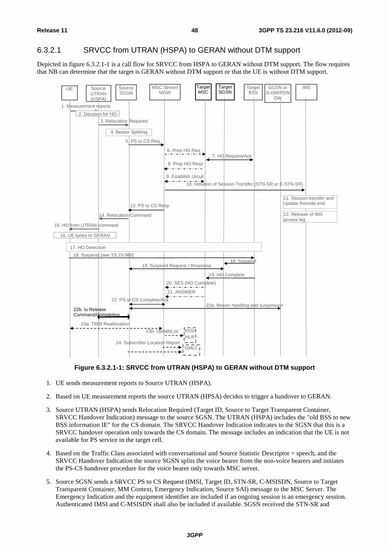
3GPP
3GPP TS 23.216 V11.6.0 (2012-09)48Release 11
6.3.2.1 SRVCC from UTRAN (HSPA) to GERAN without DTM support
Depicted in figure 6.3.2.1-1 is a call flow for SRVCC from HSPA to GERAN without DTM support. The flow requires that NB can determine that the target is GERAN without DTM support or that the UE is without DTM support.
UE Source UTRAN (HSPA)
Source SGSN
MSC Server/ MGW
Target MSC
14. Relocation Command
Target BSS
1. Measurement reports
3. Relocation Required
GGSN or S-GW/PDN
GW
2. Decision for HO
5. PS to CS Req
6. Prep HO Req 7. HO Request/Ack
8. Prep HO Resp
9. Establish circuit
19. HO Complete
20. SES (HO Complete)
21. ANSWER
13. PS to CS Resp
15. HO from UTRAN command
4. Bearer Splitting
HSS/ HLR
23b. UpdateLoc
10. Initiation of Session Transfer (STN-SR or E-STN-SR)
11. Session transfer and Update Remote end
IMS
12. Release of IMS access leg
22. PS to CS Complete/Ack
Target SGSN
16. UE tunes to GERAN
17. HO Detection 18. Suspend (see TS 23.060)
18. Suspend 18. Suspend Request / Response
22a. Bearer handling and suspension
GMLC 24. Subscriber Location Report
23a. TMSI Reallocation
22b. Iu Release Command/Completion
Figure 6.3.2.1-1: SRVCC from UTRAN (HSPA) to GERAN without DTM support
1. UE sends measurement reports to Source UTRAN (HSPA).
2. Based on UE measurement reports the source UTRAN (HPSA) decides to trigger a handover to GERAN.
3. Source UTRAN (HSPA) sends Relocation Required (Target ID, Source to Target Transparent Container, SRVCC Handover Indication) message to the source SGSN. The UTRAN (HSPA) includes the "old BSS to new BSS information IE" for the CS domain. The SRVCC Handover Indication indicates to the SGSN that this is a SRVCC handover operation only towards the CS domain. The message includes an indication that the UE is not available for PS service in the target cell.
4. Based on the Traffic Class associated with conversational and Source Statistic Descriptor = speech, and the SRVCC Handover Indication the source SGSN splits the voice bearer from the non-voice bearers and initiates the PS-CS handover procedure for the voice bearer only towards MSC server.
5. Source SGSN sends a SRVCC PS to CS Request (IMSI, Target ID, STN-SR, C-MSISDN, Source to Target Transparent Container, MM Context, Emergency Indication, Source SAI) message to the MSC Server. The Emergency Indication and the equipment identifier are included if an ongoing session is an emergency session. Authenticated IMSI and C-MSISDN shall also be included if available. SGSN received the STN-SR and

3GPP
3GPP TS 23.216 V11.6.0 (2012-09)49Release 11
C-MSISDN from the HSS as part of the subscription profile downloaded during the UTRAN (HSPA) attach procedure. The MM Context contains security related information. The CS Security key is derived by SGSN from the UTRAN (HSPA)/EPS domain key as defined in TS 33.102 [25]. The Source SAI shall be set to the Serving Area Identifier received from the source RNC.
6. The MSC Server interworks the PS handover request with a CS inter-MSC handover request by sending a Prepare Handover Request message to the target MSC. The MSC Server uses BSSMAP encapsulated for the Prepare Handover Request.
7. Target MSC performs resource allocation with the target BSS by exchanging Handover Request/ Acknowledge messages.
8. Target MSC sends a Prepare Handover Response message to the MSC Server.
9. Establishment of circuit connection between the target MSC and the MGW associated with the MSC Server e.g. using ISUP IAM and ACM messages.
10. For non-emergency session, the MSC Server initiates the Session Transfer by using the STN-SR e.g. by sending an ISUP IAM (STN-SR) message towards the IMS. For emergency session, the MSC Server initiates the Session Transfer by using the locally configured E-STN-SR and by including the equipment identifier. Standard IMS Service Continuity or Emergency IMS Service Continuity procedures are applied for execution of the Session Transfer, see TS 23.237 [14].
NOTE 1: This step can be started after step 8.
NOTE 2: If the MSC Server is using an ISUP interface, then the initiation of the session transfer for non-emergency session may fail if the subscriber profile including CAMEL triggers is not available prior handover (see clause 7.3.2.1.3 of TS 23.292 [13]), and can also fail if CAMEL triggers are available and local anchor transfer function is used (see TS 23.237 [14]). If the subscriber profile is available prior handover then CAMEL triggers others than those used in clause 7.3.2.1.3 of TS 23.292 [13] are not used during the transfer.
11. During the execution of the Session Transfer procedure the remote end is updated with the SDP of the CS access leg. The downlink flow of VoIP packets is switched towards the CS access leg at this point.
12. Source IMS access leg is released according to TS 23.237 [14].
NOTE 3: Steps 11 and 12 are independent of step 13.
13. MSC Server sends a SRVCC PS to CS Response (Target to Source Transparent Container) message to the source SGSN.
14. Source SGSN sends a Relocation Command (Target to Source Transparent Container) message to the source UTRAN (HSPA). The message includes information about the voice component only.
15. Source UTRAN (HSPA) sends a Handover Command message to the UE.
16. UE tunes to GERAN.
17. Handover Detection at the target BSS occurs. The UE sends a Handover Complete message via the target RNS/BSS to the target MSC.
18. The UE starts the Suspend procedure specified in TS 23.060 [10], clause 16.2.1.1.2. The TLLI and RAI pair are derived from the GUTI as described in TS 23.003 [27]. This triggers the Target SGSN to send a Suspend Request (Gn/Gp SGSN) or Suspend Notification (S4-SGSN) message to the Source SGSN. The Source SGSN returns a Suspend Response or Suspend Acknowledge message to the Target SGSN.
NOTE 4: This step may take place in parallel with steps 19-22.
19. Target BSS sends a Handover Complete message to the target MSC.
NOTE 5: This step may take place immediately after Handover Detection at the target BSS occurs in step 17, before the BSS has received a Suspend message from the UE.
20. Target MSC sends an SES (Handover Complete) message to the MSC Server. The speech circuit is through connected in the MSC Server/MGW according to TS 23.009 [18].

3GPP
3GPP TS 23.216 V11.6.0 (2012-09)50Release 11
21. Completion of the establishment procedure with ISUP Answer message to the MSC Server according to TS 23.009 [18].
22. MSC Server sends a SRVCC PS to CS Complete Notification message to the source SGSN, informing it that the UE has arrived on the target side. Source SGSN acknowledges the information by sending a SRVCC PS to CS Complete Acknowledge message to the MSC Server.
22a. After the SGSN received a Suspend Request/Notification in step 18, the SGSN behaves as follows:
If the SGSN uses Gn/Gp based interaction with GGSN, then:
- The SGSN deactivates PDP Contexts used for voice and it suspends PDP Contexts using background or interactive class.
- For a PDP Context using streaming or conversational traffic class not used for voice, the PDP Context is preserved and the maximum bitrate is downgraded to 0 Kbit/s.
If the SGSN uses S4 based interaction with S-GW and P-GW, then:
- The SGSN deactivates bearers used for voice and other GBR bearers towards S-GW and P-GW by initiating MS-and SGSN Initiated Bearer Deactivation procedure as specified in TS 23.060 [10]. PS-to-CS handover indicator is notified to P-GW for voice bearer during the bearer deactivation procedure.
- If dynamic PCC is deployed, the P-GW may interact with PCRF as defined in TS 23.203 [32].
- The SGSN starts preservation and suspension of non-GBR bearers by sending Suspend Notification message towards S-GW. The S-GW releases all RNC related information (address and TEIDs) for the UE if Direct Tunnel is established, and sends Suspend Notification message to the P-GW(s).
The SGSN stores in the UE context that UE is in suspended status. All the preserved non-GBR bearers are marked as suspended status in the S-GW and P-GW. The P-GW should discard packets if received for the suspended UE.
22b) The source SGSN sends a Iu Release Command to the Source RNC. The Source RNC releases its resources related to the UE and responds with an Iu Release Complete message.
23a. If the HLR is to be updated, i.e. if the IMSI is authenticated but unknown in the VLR, the MSC Server performs a TMSI reallocation towards the UE using its own non-broadcast LAI and, if the MSC Server and other MSC/VLRs serve the same (target) LAI, with its own Network Resource Identifier (NRI).
NOTE 6: The TMSI reallocation is performed by the MSC Server towards the UE via target MSC.
23b. If the MSC Server performed a TMSI reallocation in step 23a, and if this TMSI reallocation was completed successfully, the MSC Server performs a MAP Update Location to the HSS/HLR.
NOTE 7: This Update Location is not initiated by the UE.
24. For an emergency services session after handover is complete, the source SGSN or the MSC Server may send a Subscriber Location Report carrying the identity of the MSC Server to a GMLC associated with the source or target side, respectively, as defined in TS 23.271 [29] to support location continuity.
NOTE 8: Any configuration of the choice between a source SGSN versus MSC Server update to a GMLC needs to ensure that a single update occurs from one of these entities when the control plane location solution is used on the source and/or target sides.
After the CS voice call is terminated and if the UE is still in GERAN or UTRAN (or for any other reason according to TS 24.008), then the UE shall resume PS services (as specified in TS 23.060 [10]). A Gn/Gp SGSN will follow TS 23.060 [10] to resume the PDP Context(s). An S4-SGSN will also follow TS 23.060 [10] to resume the bearers, and will in addition inform S-GW and P-GW(s) to resume the suspended bearers. Resuming the suspended bearers in the S-GW and in the P-GW should be done by implicit resume using the Modify Bearer request message if it is triggered by the procedure in operation, e.g. RAU, TAU or Service Request. The S-GW is aware of the suspend state of the bearers and will forward the Modify Bearer request to the P-GW. Explicit resume using the Resume Notification message should be used in cases when Modify Bearer Request is not triggered by the procedure in operation.

3GPP
3GPP TS 23.216 V11.6.0 (2012-09)51Release 11
6.3.2.1A SRVCC from UTRAN (HSPA) to GERAN with DTM but without DTM HO support and from UTRAN (HSPA) to UTRAN without PS HO
The call flow for this scenario is similar to the call flow depicted in figure 6.3.2.1-1, with the exceptions that the Suspend procedure (step 18 and step 22a in figure 6.3.2.1-1) is not performed and that the source SGSN only deactivates bearers used for voice and sets the PS-to-CS handover indicator. The scenario requires that NB can determine that the target is either GERAN with DTM but without DTM HO support and that the UE is supporting DTM or that the target is UTRAN (HSPA) without PS HO support. The message in step 3 in figure 6.3.2.1 1 includes an indication to the SGSN that the UE is available for PS service in the target cell. At the end of the procedure described in figure 6.3.2.1-1, the remaining PS resources are re-established when the UE performs the Routeing Area update procedure. Triggers for performing Routeing Area update procedure are described in TS 23.060 [10]. The target SGSN may deactivate the PDP contexts that cannot be established as described in TS 23.060 [10].
6.3.2.2 SRVCC from UTRAN (HSPA) to UTRAN or GERAN with DTM HO support
Depicted in figure 6.3.2.2-1 is a call flow for SRVCC from UTRAN (HSPA) to UTRAN or GERAN with DTM HO support, including the handling of the non voice component.
2b. SRVCC CS Keys Response
2a. SRVCC CS Keys Request
13. Relocation Command
1. Measurement reports
3. Relocation Required
2. Decision for HO
5a. PS to CS Req
17a. Reloc/HO Complete
17b. SES (HO Complete)
17c. ANSWER
12. PS to CS Resp
18a. Reloc/HO Complete
18c. Update bearer
HSS/ HLR 17g. UpdateLoc
5b. Prep HO Req
8b. Prep HO Resp
8c. Establish circuit
6a. Forward Reloc Req 6b. Reloc / HO Req
5c. Reloc /HO Req
8a. Reloc/HO Req Ack
7b. Forward Reloc Resp 7a. Reloc/HO Req Ack
11. Release of IMS access leg
10. Session transfer and Update Remote end
9. Initiation of Session Transfer (STN-SR or E-STN-SR)
UE Source UTRAN (HSPA)
Source SGSN
MSC Server/ MGW
Target MSC
Target RNS/BSS
SGW/ PGW/ GGSN
IMS Target SGSN
14. HO from UTRAN command
17d. PS to CS Complete/Ack
18b. Forward Reloc Complete/Ack
16. HO Detection
4. Bearer Splitting
15. UE tunes to UTRAN/GERAN
GMLC 19. Subscriber Location Report
17f. TMSI Reallocation
17e. Delete bearer
18d. Delete Session 18e. Iu Release Command/Completion
Figure 6.3.2.2-1: SRVCC from UTRAN (HSPA) to UTRAN or GERAN with DTM HO support
1. UE sends measurement reports to Source UTRAN (HSPA).

3GPP
3GPP TS 23.216 V11.6.0 (2012-09)52Release 11
2. Based on UE measurement reports the source UTRAN (HSPA) decides to trigger a handover to UTRAN/GERAN.
2a. In case of SRVCC to UTRAN the RNC shall initiate the SRVCC Preparation procedure by sending an SRVCC CS KEYS REQUEST message to the source SGSN.
2b. The SGSN shall respond to the RNC with SRVCC CS KEYS RESPONSE message containing the Integrity Protection Key IE, the Encryption Key IE and the SRVCC Information IE.
3. If target is UTRAN, the source UTRAN (HSPA) sends a Relocation Required (Target ID, Source RNC to Target RNC Transparent Container, SRVCC Handover Indication) message to the source SGSN. UTRAN (HSPA) also indicates to SGSN that this is for CS+PS HO.
NOTE 1: When the source UTRAN (HSPA) indicates that this is a CS+PS HO request, the source SGSN sends the single received transparent container to both the target CS domain and the target PS domain.
If target is GERAN, the source UTRAN (HSPA) sends a Relocation Required (Target ID, Old BSS to New BSS Information IE for the CS domain and Source BSS to Target BSS Transparent Container for the PS Domain, SRVCC Handover Indication) message to the source SGSN. The differentiation between CS and PS containers is described in TS 25.413 [11]. In this case, the SGSN identifies from the SRVCC Handover Indication that this is a request for a CS+PS handover.
4. Based on the Traffic Class associated with conversational and Source Statistic Descriptor = speech, and the SRVCC Handover Indication the Source SGSN splits the voice bearer from all other PS bearers and initiates their relocation towards MSC Server and SGSN, respectively.
5a) Source SGSN initiates the PS-CS handover procedure for the voice bearer by sending a SRVCC PS to CS Request (IMSI, Target ID, STN-SR, C-MSISDN, Source to Target Transparent Container, MM Context, Emergency Indication, Source SAI) message to the MSC Server. The Emergency Indication and the equipment identifier are included if the ongoing session is emergency session. Authenticated IMSI and C-MSISDN shall be included if available. The message includes information relevant to the CS domain only. SGSN received STN-SR and C-MSISDN from the HSS as part of the subscription profile downloaded during the UTRAN (HSPA) attach procedure. MM Context contains security related information. The CS Security key is derived by the SGSN from the UTRAN (HSPA)/EPS domain key as defined in TS 33.102 [25]. If the target system is GERAN, the Source SAI shall be set to the Serving Area Identifier received from the source RNC.
5b) MSC Server interworks the PS handover request with a CS inter-MSC handover request by sending a Prepare Handover Request message to the target MSC. If the target system is GERAN, MSC Server uses BSSMAP encapsulated for the Prepare Handover Request. If the target system is UTRAN, MSC Server uses RANAP encapsulated for the Prepare Handover Request.
5c) Target MSC requests resource allocation for the CS relocation by sending the Relocation Request/Handover Request (Source to Target Transparent Container) message to the target RNS/BSS.
6. In parallel to the previous step the source SGSN initiates relocation of the PS bearers. The following steps are performed (for details see TS 23.060 [10]):
a) If the target SGSN uses S4 based interaction with S-GW and P-GW, the source SGSN sends a Forward Relocation Request (Source to Target Transparent Container, MM Context, PDP Context) message to the target SGSN. The PDP Context includes bearer information for all bearers except the voice bearer. The handling of security keys for PS handover of the remaining non-voice PS bearers is specified in TS 33.401 [22].
If the target SGSN uses Gn/Gp based interaction with GGSN, the Source SGSN sends a Forward Relocation Request (Source to Target Transparent Container, MM Context and PDP Context) message to the target SGSN. The PDP Context includes bearer information for all bearers except the voice bearer. The handling of security keys for PS handover of the remaining non-voice PS bearers is specified in TS 33.102 [25].
b) Target SGSN requests resource allocation for the PS relocation by sending the Relocation Request/Handover Request (Source to Target Transparent Container) message to the target RNS/BSS.
7. Target RNS/BSS coordinates the CS relocation request with the PS relocation request and assigns resources. The following steps are performed:
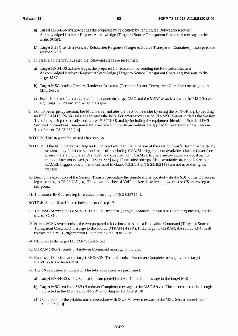
3GPP
3GPP TS 23.216 V11.6.0 (2012-09)53Release 11
a) Target RNS/BSS acknowledges the prepared PS relocation by sending the Relocation Request Acknowledge/Handover Request Acknowledge (Target to Source Transparent Container) message to the target SGSN.
b) Target SGSN sends a Forward Relocation Response (Target to Source Transparent Container) message to the source SGSN.
8. In parallel to the previous step the following steps are performed:
a) Target RNS/BSS acknowledges the prepared CS relocation by sending the Relocation Request Acknowledge/Handover Request Acknowledge (Target to Source Transparent Container) message to the target MSC.
b) Target MSC sends a Prepare Handover Response (Target to Source Transparent Container) message to the MSC Server.
c) Establishment of circuit connection between the target MSC and the MGW associated with the MSC Server e.g. using ISUP IAM and ACM messages.
9. For non-emergency session, the MSC Server initiates the Session Transfer by using the STN-SR e.g. by sending an ISUP IAM (STN-SR) message towards the IMS. For emergency session, the MSC Server initiates the Session Transfer by using the locally-configured E-STN-SR and by including the equipment identifier. Standard IMS Service Continuity or Emergency IMS Service Continuity procedures are applied for execution of the Session Transfer, see TS 23.237 [14].
NOTE 2: This step can be started after step 8b.
NOTE 3: If the MSC Server is using an ISUP interface, then the initiation of the session transfer for non-emergency sessions may fail if the subscriber profile including CAMEL triggers is not available prior handover (see clause 7.3.2.1.3 of TS 23.292 [13]), and can also fail if CAMEL triggers are available and local anchor transfer function is used (see TS 23.237 [14]). If the subscriber profile is available prior handover then CAMEL triggers others than those used in clause 7.3.2.1.3 of TS 23.292 [13] are not used during the transfer.
10. During the execution of the Session Transfer procedure the remote end is updated with the SDP of the CS access leg according to TS 23.237 [14]. The downlink flow of VoIP packets is switched towards the CS access leg at this point.
11. The source IMS access leg is released according to TS 23.237 [14].
NOTE 4: Steps 10 and 11 are independent of step 12.
12. The MSC Server sends a SRVCC PS to CS Response (Target to Source Transparent Container) message to the source SGSN.
13. Source SGSN synchronises the two prepared relocations and sends a Relocation Command (Target to Source Transparent Container) message to the source UTRAN (HSPA). If the target is GERAN, the source RNC shall receive the SRVCC Information IE containing the NONCE IE.
14. UE tunes to the target UTRAN/GERAN cell.
15. UTRAN (HSPA) sends a Handover Command message to the UE.
16. Handover Detection at the target RNS/BSS. The UE sends a Handover Complete message via the target RNS/BSS to the target MSC.
17. The CS relocation is complete. The following steps are performed:
a) Target RNS/BSS sends Relocation Complete/Handover Complete message to the target MSC.
b) Target MSC sends an SES (Handover Complete) message to the MSC Server. The speech circuit is through connected in the MSC Server/MGW according to TS 23.009 [18].
c) Completion of the establishment procedure with ISUP Answer message to the MSC Server according to TS 23.009 [18].

3GPP
3GPP TS 23.216 V11.6.0 (2012-09)54Release 11
d) MSC Server sends a SRVCC PS to CS Complete Notification message to the source SGSN. Source SGSN acknowledges the information by sending a SRVCC PS to CS Complete Acknowledge message to the MSC Server.
e) The source SGSN deletes the voice bearer towards GGSN/S-GW/P-GW and sets the PS-to-CS handover indicator. If dynamic PCC is deployed, the PGW may interact with PCRF as defined in TS 23.203 [32].
f) If the HLR is to be updated, i.e. if the IMSI is authenticated but unknown in the VLR, the MSC Server performs a TMSI reallocation towards the UE using its own non-broadcast LAI and, if the MSC Server and other MSC/VLRs serve the same (target) LAI, with its own Network Resource Identifier (NRI).
NOTE 5: The TMSI reallocation is performed by the MSC Server towards the UE via target MSC.
g) If the MSC Server performed a TMSI reallocation in step 17f, and if this TMSI reallocation was completed successfully, the MSC Server performs a MAP Update Location to the HSS/HLR.
NOTE 6: this Update Location is not initiated by the UE.
18. In parallel to the previous step, the PS relocation is complete. The following steps are performed:
a) Target RNS/BSS sends Relocation Complete/Handover Complete message to target SGSN.
b) Target SGSN sends a Forward Relocation Complete message to the source SGSN. After having completed step 17e, source SGSN acknowledges the information by sending a Forward Relocation Complete Acknowledge message to the target SGSN.
c) Target SGSN updates the bearer with GGSN/S-GW/P-GW.
d) The Source S4-SGSN sends delete Session Request to the SGW as defined in TS 23.401 [2].
e) The source SGSN sends a Iu Release Command to the Source RNC. The Source RNC releases its resources related to the UE and responds with an Iu Release Complete message.
NOTE 7: Routing Area Update procedures by the UE are done in accordance with TS 23.060 [10].
19. For an emergency services session after handover is complete, the source SGSN or the MSC Server may send a Subscriber Location Report carrying the identity of the MSC Server to a GMLC associated with the source or target side, respectively, as defined in TS 23.271 [29] to support location continuity.
NOTE 8: Any configuration of the choice between a source SGSN versus MSC Server update to a GMLC needs to ensure that a single update occurs from one of these entities when the control plane location solution is used on the source and/or target sides.
In case the SGSN determines that only the relocation of the voice bearer but not the relocation of one or more PS bearers succeeds, then the SGSN proceeds step13 after receiving SRVCC PS to CS Response from the MSC Server in step 12 and both UE and SGSN continue the procedure described in clause 6.3.2.1A.
6.4 UTRAN/GERAN to E-UTRAN/UTRAN (HSPA) SRVCC
6.4.1 GPRS Attach procedure for SRVCC GPRS attach procedure is performed as follows:
- If the subscriber is allowed to have CS to PS SRVCC, the HSS shall include the "CS to PS SRVCC allowed" indication in the Insert Subscriber Data sent to the MSC Server. The "CS to PS SRVCC allowed" indication may be specific for each VPLMN.
6.4.2 E-UTRAN Attach procedure for SRVCC E-UTRAN attach procedure for 3GPP CS to PS SRVCC UE is performed as defined in TS 23.401 [2].

3GPP
3GPP TS 23.216 V11.6.0 (2012-09)55Release 11
6.4.3 Call flows for SRVCC to E-UTRAN/UTRAN (HSPA)
6.4.3.1 SRVCC to E-UTRAN/UTRAN (HSPA) from GERAN without DTM/PS HO support
Depicted in Figure 6.4.3.1-1 is an overview call flow for SRVCC to E-UTRAN/UTRAN (HSPA) from GERAN without DTM/PS HO support. The flow is based on the assumption that the source is GERAN without DTM/PS HO support or that the UE is without DTM/PS HO support and that all PS bearers are suspended.
The CS to PS SRVCC procedure will only be successfully performed under the following conditions:
- the UE has indicated to be CS to PS capable,
- the CS to PS allowed indication was part of the subscriber data received from HSS,
- the UE is IMS registered; and
- the UE has at least one PS bearer (usable for SIP signalling).
1a Retrieval of PS registration information
UE - 1 Old
MME / SGSN SGW / PGW
BSC / RNC
MSC Server PCRF
1 . HO required
3 . CS to PS HO request
NB / eNB
6 . Allocate resources
11 . Handover Notify
8 b . CS to PS HO command
Target MME / SGSN
IMS
9 . Session Transfer Preparation request
2 . Session Transfer Notification
4 . Context Request
5 . Context Response
7 . CS to PS HO response 8 a . CS to PS HO
command
10 . CS to PS HO confirmation
12 . Modify bearers
16. Bearer setup / PDP Context setup .
15. UE Initiated Session transfer procedure
13. Context Acknowledge
11 a . CS to PS Complete/Ack
14. Release Resource
Figure 6.4.3.1-1: SRVCC to E-UTRAN/UTRAN (HSPA) from UTRAN/GERAN without DTM / PS HO
NOTE 1: For SRVCC to UTRAN (HSPA) the target SGSN may use Gn/Gp for the connection to the GGSN/PGW SGSN. In that case SGSN uses GTPv1 signalling, i.e. send Update PDP Context Request in step 12 and the user plane path is established for all bearers between the UE, target NodeB, the SGSN and the SGW/PGW (GGSN) and use the GTPv1 version of the SGSN Context Request in steps 4 and 5. Furthermore, the step 16 is triggered for the setup of a Secondary PDP Context instead of a Dedicated Bearer.
1. The RNC/BSC sends a HO required to the MSC Server including an indication this HO is for CS to PS. If an inter-MSC CS HO has occurred prior to the CS to PS HO procedure, the MSC Server forwards the HO required to the anchor MSC Server.
1a. The MSC retrieves P-TMSI+RAI+P-TMSI signature or GUTI from the UE.
2. The MSC Server sends an Session Transfer Notification to IMS, which indicates that IMS should prepare for the transfer of media to PS. IMS allocates media ports in the network for the transfer. The media ports and codec information allocated by IMS are provided to the MSC Server in the response message

3GPP
3GPP TS 23.216 V11.6.0 (2012-09)56Release 11
3. The MSC Server selects the target MME/SGSN based on Target ID contained in the HO required and sends a SRVCC CS to PS HO request to the target MME/SGSN. If required, the IMSI is provided for identifying the UE, and the GUTI or P-TMSI, P-TMSI signature and RAI as provided by the UE (see clause 5.3.4.3) are provided to the target MME/SGSN.
NOTE 2: Step 2 and Step 3 can be performed independently of each other.
4. If the target MME/SGSN has no UE context it sends Context Request using GUTI or P-TMSI, P-TMSI signature and RAI to find the old MME/SGSN.
5. The old MME/SGSN responds with Context Response message including all UE contexts.
6. The target MME/SGSN allocates resources for all PS bearers in E-UTRAN or UTRAN (HSPA). The target MME/SGSN determines if the Serving GW is to be relocated, e.g. due to PLMN change.
7. A SRVCC CS to PS HO response is returned from the target MME/SGSN to the MSC Server.
8. MSC Server sends CS to PS command to the RAN, possibly via the target MSC, and the RAN send HO command to UE, indicating CS to PS handover. The MSC Server also includes in that message the IP address/ports and selected codec for the IMS media anchoring.
9. A Session Transfer Preparation Request is sent to IMS to trigger IMS to have the media path switched to the IP address/port of the UE on the target access.
10. The UE sends Handover confirmation to the eNodeB/NodeB.
11. The eNodeB send Handover Notify to the MME/SGSN.
11a. The MME/SGSN sends a SRVCC CS to PS Complete Notification message to the MSC Server to confirm the completion of the handover. The source MSC Server acknowledges the information by sending a SRVCC CS to PS Complete Acknowledge message to the MME/SGSN. When receiving the SRVCC CS to PS Complete Notification message, the MSC Server may release the local resource toward the BSS/RAN but not for the resources toward IMS (i.e. will not send any session release towards IMS).
12. The MME/S4-SGSN sends Modify Bearer Request to the SGW, which may be forwarded to the PGW to update PS bearer contexts according to IRAT HO procedure as specified in TS 23.401 [2]. At this stage the user plane path is established for all bearers between the UE, target eNodeB/NodeB, Serving GW (for Serving GW relocation this will be the Target Serving GW) and PDN GW and the voice session may continue temporarily on the default bearer until the dedicated bearer has been setup.
In this procedure, the MME/SGSN includes the CS to PS SRVCC indication. When dynamic PCC is deployed and PCRF has subscribed to the corresponding event as specified in TS 23.203 [32], the CS to PS indication is provided to the PCRF. This causes PCRF to make policy decisions to permit traffic towards the ATGW on the default bearer. Otherwise, when GTP is used, the PGW can install the filters locally to allow the default bearer to temporarily permit traffic towards the configured ATGWs.
NOTE 3: An alternative of using temporary filters on the default bearers is to ensure that the filters are always open towards the IMS ATGW. As the ATGW is a media gateway, such gateway will ensure that non-authorized media cannot be sent through the system.
13. If the target MME/SGSN has received Context Response from the old SGSN/MME, the target MME/SGSN sends the Context Acknowledge to the Context Response to the old SGSN/MME. A timer in the old SGSN is started to supervise when resources in the old BSC/RNC and the old Serving GW (for Serving GW relocation) shall be released according to IRAT HO procedure as specified in TS 23.401 [2].
14. When the timer at the old SGSN started in step 13 expires, the old SGSN will clean-up all its resources towards old BSC/RNC if the UE is Iu/Gb Connected.
15. The UE initiates the Session transfer procedures according to TS 23.237 [14].
16. As a result of the Session transfer procedures, the setup of a dedicated bearer or PDP Context for voice is performed according to the dedicated bearer/PDP Context activation procedure as specified in TS 23.401 [2] or TS 23.060 [10]. After the setup of a dedicated bearer for voice and the respective filters in UE and PGW, the default bearer is not longer used for voice media and the PCRF revert any policy decision made in step 12 for the purpose of CS to PS SRVCC procedures.

3GPP
3GPP TS 23.216 V11.6.0 (2012-09)57Release 11
NOTE 4: Where the bearer contexts are suspended depends on if the CS call was triggered by SRVCC from E-UTRAN or from CS procedures while the UE was attached to 2G/3G. If the CS call was triggered by SRVCC from E-UTRAN the bearers are suspended in an MME, and step 4 is sent to the old MME only in case of MME change, or if the CS call was triggered while UE was in 2G/3G, the bearers are suspended in the old SGSN. The new MME uses P-TMSI and RAI or the GUTI received from the MSC in the SRVCC CS to PS HO request to find the old SGSN/MME.
NOTE 5: The UE will trigger the TAU according to TS 23.401 [2] if the target network is E-UTRAN or a Routing Area Update according to TS 23.060 [10] if the target network is UTRAN. The MME/SGSN knows that this relates to the CS to PS SRVCC procedures.
6.4.3.2 SRVCC to E-UTRAN/UTRAN (HSPA) from GERAN with DTM support but without DTM HO support and from UTRAN without PS HO support
The call flow for this scenario is similar to the call flow depicted in figure 6.4.3.1-1, except that the old PS node in this case is an SGSN and step 4 is performed towards the old SGSN which is in the same routing area as the BSC/RNC. The target MME/SGSN shall send Context Request using P-TMSI and RAI to find the old SGSN to obtain the bearer contexts of the UE.
6.4.3.3 SRVCC to E-UTRAN/UTRAN (HSPA) with DTM/PS HO support
The call flow for this scenario is similar to the call flow depicted in figure 6.4.3.1-1, with the clarification that the BSC/RNC shall only send CS to PS HO required to MSC Server when CS to PS HO is supposed to be triggered. The PS to PS HO required shall not be sent to the old SGSN. Hence, no PS HO signalling is initiated. The target MME/SGSN shall send Context Request using P-TMSI and RAI to find the old SGSN to obtain the bearer contexts of the UE.
7 Charging See TS 23.292 [13] clause 8 on charging for guidance on the handling of charging for SRVCC.
8 Handover Failure
8.1 Failure in EUTRAN/UTRAN (HSPA) to 3GPP UTRAN/GERAN (v)SRVCC
8.1.1 Failure before MSC Server initiates Session Transfer If a failure is encountered before the MSC Server initiates Session Transfer, then the standardised handover failure procedures apply according to TS 23.401 [2]. No further action is required by the UE.
8.1.1a Failure after MSC Server initiates Session Transfer
8.1.1a.1 Failure before responding to PS to CS HO request
If the MSC Server receives a negative response from IMS during the Session Transfer procedure (e.g., due to invalid STN-SR, or temporary failure, etc) and the MSC Server has not yet responded back to MME/SGSN with a positive PS to CS Response message due to successful target CS radio resource reservation, then MSC Server shall reject this PS To CS Request with a Reject cause pointing to either permanent or temporary "Session Transfer leg establishment error" and MSC Server shall release the CS radio resource at the target RAT.
NOTE 1: An example of permanent error can be an invalid STN-SR (i.e., IMS returns with "404 user unknown").

3GPP
3GPP TS 23.216 V11.6.0 (2012-09)58Release 11
When MME/SGSN receives the PS to CS Response with a reject cause related to "permanent Session Transfer leg establishment error", MME/SGSN may take that indication into account to prevent further SRVCC handover attempts.
NOTE 2: It is an implementation option on when the MME/SGSN may retry SRVCC after receiving a "permanent Session Transfer leg establishment error".
The following figure 8.1.1a-1 shows the overall procedure when the MSC Server aware of the Session Transfer failure prior to responding to PS to CS HO request.
UE
Source E- UTRAN /
UTRAN Source MME/SGSN
MSC Server IMS
SRVCC Procedure started by Source E - UTRAN/ UTRAN , MME /SGSN sends PS to CS Request to MSC Server , MSC Server is requesting resources from target CS RAT .
Session Transfer with INVITE ( STN - SR ..)
Failure ( Session Transfer leg establishment error)
PS to CS Response ( Reject cause = Session Transfer leg establishment error )
Handover Prep Failure ( cause ) Clear target CS RAT
Figure 8.1.1a-1: SRVCC Handover Rejection due to Session Transfer leg establishment error before responding to PS to CS HO request
8.1.1a.2 Failure after responding to PS to CS HO request
If the MSC Server receives a negative response from IMS during the initiates Session Transfer procedure (e.g. due to invalid STN-SR, or temporary failure, etc) and the MSC Server has already responded back to MME/SGSN with a positive PS to CS Response message due to successful target CS radio resource reservation, then MSC Server shall indicate to MME/SGSN with an error cause pointing to either permanent or temporary "Session Transfer leg establishment error" in PS to CS complete notification message, MME/SGSN shall perform the bearer release procedure as according to the normal SRVCC procedure as defined in clauses 6.2 and 6.3.
When MME/SGSN receives this PS to CS Complete notification message with an error cause pointing to "permanent Session Transfer leg establishment error", MME/SGSN may take that indication into account to prevent further SRVCC handover attempts.
The following figure 8.1.1a-2 shows the overall procedure when the MSC Server aware of the Session Transfer failure after the PS to CS HO request has been responded to MME/SGSN.

3GPP
3GPP TS 23.216 V11.6.0 (2012-09)59Release 11
UE
Source E- UTRAN /
UTRAN Source MME /SGSN
MSC Server IMS
SRVCC Procedure started by Source E- UTRAN /UTRAN , MME /SGSN sends PS to CS Request to MSC Server , MSC Server is requesting resources from target
CS RAT .
Session Transfer with INVITE ( STN - SR ..)
Failure ( Session Transfer leg establishment error)
PS to CS Response ( Positive response )
PS to CS Complete ( error = Session Transfer leg establishment error )
Call release
HO Command Switch to CS
RAT
Figure 8.1.1a-1: SRVCC Handover Rejection due to Session Transfer leg establishment error after responding to PS to CS HO request
8.1.2 Failure after UE receives HO command If the UE encounters a failure at the radio level after it receives the handover command and does not successfully transition to 3GPP UTRAN/GERAN RAT, the UE attempts to return to E-UTRAN/UTRAN by sending a re-INVITE to the SCC AS. The core network (MME, MSC Server) shall take no (v)SRVCC specific action in the event of not receiving the Handover Complete message from the UE.
8.1.3 Handover Cancellation If the source E-UTRAN/UTRAN decides to terminate the handover procedure before its completion, the MME/SGSN shall return to its state before the handover procedure was triggered. The MME/SGSN attempts to trigger, at the MSC Server enhanced for SRVCC, handover cancellation procedures according to TS 23.009 [18]. The MSC Server enhanced for SRVCC shall take no SRVCC-specific action towards IMS.
The MME/SGSN shall also send a session reestablishment trigger notification to UE to start the recovery procedure if it receives notification from the MSC Server that the Session Transfer procedure is in progress. Figure 8.1.3-1 shows the overall procedure for SRVCC handover cancellation.
For vSRVCC the MME and MSC also behave the same way as in the case of SRVCC handover cancellation.
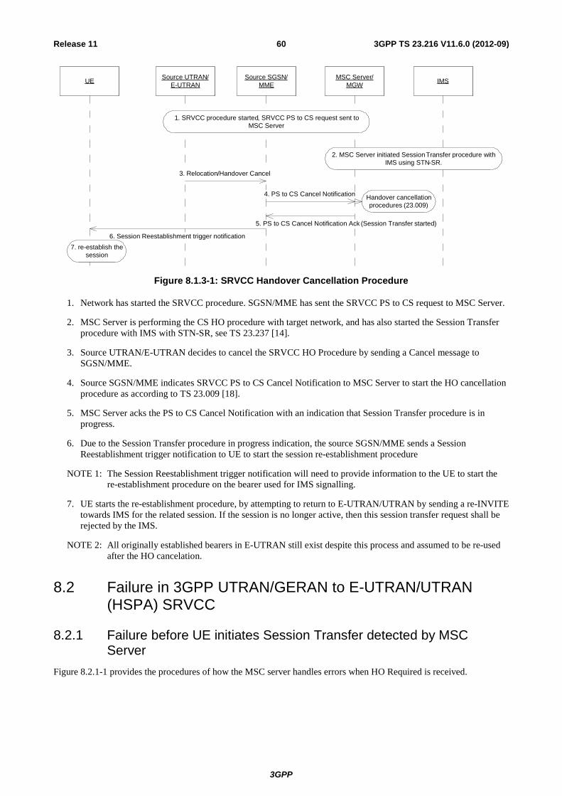
3GPP
3GPP TS 23.216 V11.6.0 (2012-09)60Release 11
UE Source UTRAN /
E - UTRAN Source SGSN /
MME MSC Server /
MGW IMS
1 . SRVCC procedure started , SRVCC PS to CS request sent to MSC Server
2 . MSC Server initiated Session Transfer procedure with IMS using STN - SR .
3 . Relocation / Handover Cancel
Handover cancellation procedures ( 23 . 009 )
6 . Session Reestablishment trigger notification
4 . PS to CS Cancel Notification
5 . PS to CS Cancel Notification Ack ( Session Transfer started )
7 . re - establish the session
Figure 8.1.3-1: SRVCC Handover Cancellation Procedure
1. Network has started the SRVCC procedure. SGSN/MME has sent the SRVCC PS to CS request to MSC Server.
2. MSC Server is performing the CS HO procedure with target network, and has also started the Session Transfer procedure with IMS with STN-SR, see TS 23.237 [14].
3. Source UTRAN/E-UTRAN decides to cancel the SRVCC HO Procedure by sending a Cancel message to SGSN/MME.
4. Source SGSN/MME indicates SRVCC PS to CS Cancel Notification to MSC Server to start the HO cancellation procedure as according to TS 23.009 [18].
5. MSC Server acks the PS to CS Cancel Notification with an indication that Session Transfer procedure is in progress.
6. Due to the Session Transfer procedure in progress indication, the source SGSN/MME sends a Session Reestablishment trigger notification to UE to start the session re-establishment procedure
NOTE 1: The Session Reestablishment trigger notification will need to provide information to the UE to start the re-establishment procedure on the bearer used for IMS signalling.
7. UE starts the re-establishment procedure, by attempting to return to E-UTRAN/UTRAN by sending a re-INVITE towards IMS for the related session. If the session is no longer active, then this session transfer request shall be rejected by the IMS.
NOTE 2: All originally established bearers in E-UTRAN still exist despite this process and assumed to be re-used after the HO cancelation.
8.2 Failure in 3GPP UTRAN/GERAN to E-UTRAN/UTRAN (HSPA) SRVCC
8.2.1 Failure before UE initiates Session Transfer detected by MSC Server
Figure 8.2.1-1 provides the procedures of how the MSC server handles errors when HO Required is received.

3GPP
3GPP TS 23.216 V11.6.0 (2012-09)61Release 11
BSC / RNC MSC Server
2 . Detect CS to PS SRVCC not possible
3 . HO Cancellation
1 . HO Required
Figure 8.2.1-1: Error handling during HO
1. The RNC/BSC sends a HO required to the MSC Server including an indication this HO is for CS to PS SRVCC.
2. The MSC Server checks if CS to PS HO is possible, e.g., that the UE is still registered in IMS. In this flow, the MSC Server detects that CS to PS SRVCC cannot be performed.
3. MSC Server cancels the HO with a specific cause that the RNC/BSC will not perform further HO attempts for CS to PS SRVCC.
If the HO cancellation is done prior that the Session Transfer Preparation request, but after the Session Transfer Notification, the MSC Server shall send a notification session transfer cancellation to IMS to indicate that the transfer has been cancelled to allow IMS to de-allocate any resources it may have reserved.
8.2.2 Failure before UE initiates Session Transfer detected by MME Figure 8.2.2-1 provides the procedures of how the MSC server handles errors when HO Required is received.
BSC / RNC
MSC Server
5 . HO Cancellation
1 . HO Required
Target MME
2 . CS to PS Request
4 . CS to PS Response
3 . Detect CS to PS SRVCC not possible
Figure 8.2.2-1: Error handling during HO
1. The RNC/BSC sends a HO required to the MSC Server including an indication this HO is for CS to PS. If the MSC Server is the target MSC, it forwards the HO required to the anchor MSC Server.
2. The MSC Server sends a SRVCC CS to PS Request to the Target MME. If required, the IMSI is provided for identifying the UE, and the P-TMSI and RAI is provided to MME if available.
3. The MME has no UE context and tries to find the source SGSN/MME. For some reason, the UE context cannot be found. The MME cancels the HO.
4. The MME sends SRVCC CS to PS Response, with cause indicating failure, to the MSC Server.
5. MSC Server cancels the HO with a specific cause that the RNC/BSC will not perform further HO attempts for CS to PS SRVCC.

3GPP
3GPP TS 23.216 V11.6.0 (2012-09)62Release 11
The cancellation is done prior that the Session Transfer Preparation request, but after the Session Transfer Notification, the MSC Server shall send a notification session transfer cancellation to IMS to indicate that the transfer has been cancelled to allow IMS to de-allocate any resources it may have reserved.
8.2.3 CS to PS Handover Cancellation If the source RAN decides to terminate the handover procedure before its completion, the MSC Server shall start the Cancellation procedure if it has initiated the CS to PS HO command towards the MME. Figure 8.2.3-1 shows the overall procedure for SRVCC CS to PS handover cancellation.
BSC/ RNC MSC Server
6 . Ack
1 . HO Required
Target MME
2. CS to PS HO cmd
5 . CS to PS Cancel ack
3. Relocation / HO Cancel 4 . CS to PS Cancel
notification
Figure 8.2.3-1: SRVCC CS to PS Handover Cancellation Procedure
1-2. Network has started the SRVCC CS to PS procedure. MSC Server has sent the SRVCC CS to PS request to MME. MME is performing the SRVCC CS to PS HO procedure with target network.
3. Source RAN decides to cancel the SRVCC CS to PS HO Procedure by sending a Cancel message to MSC Server.
4. Source MSC Server indicates SRVCC CS to PS Cancel Notification to MME to start the HO cancellation procedure.
5. MME acks the CS to PS Cancel Notification.
6. The MSC Server acknowledges the HO Cancelation from BSC/RNC and resumes the CS session.
If the HO cancellation is done prior that the Session Transfer Preparation request, but after the Session Transfer Notification, the MSC Server shall send a Session Transfer Notification cancellation to IMS to indicate that the transfer has been cancelled to allow IMS to de-allocate any resources it may have reserved.
9 Security
9.1 Network Domain Security with 3GPP2 1xCS IWS Network domain security with 3GPP2 1xCS IWS shall be provided by NDS/IP according to TS 33.210 [21] with integrity protection and confidentiality. This shall be applied whenever signalling messages (e.g. containing security context) are transferred on the S102 reference point.
NOTE 1: In case control plane interfaces are trusted (e.g. physically protected), there is no need to use protection according to TS 33.210 [21].

3GPP
3GPP TS 23.216 V11.6.0 (2012-09)63Release 11
9.2 Network Domain Security with 3GPP UTRAN/GERAN MSC Server
Network domain security with 3GPP UTRAN/GERAN MSC Server shall be provided by NDS/IP according to TS 33.210 [21] with integrity protection and confidentiality. This shall be applied whenever signalling messages (e.g. containing security context) are transferred on the Sv reference point.
NOTE 2: In case control plane interfaces are trusted (e.g. physically protected), there is no need to use protection according to TS 33.210 [21].

3GPP
3GPP TS 23.216 V11.6.0 (2012-09)64Release 11
Annex A (informative): Determination of Neighbour Cell List This annex describes example algorithms for determination of Neighbour Cell List (NCL) for SRVCC operation. In case of SRVCC to GERAN/UTRAN it is also clarified when the E-UTRAN includes a SRVCC indication in the Handover Required message.
A.1 SRVCC from E-UTRAN to 3GPP2 1xCS E-UTRAN may determine the NCL as follows:
- If the "SRVCC operation possible" indication is set to "true" (i.e. both EPC and UE are SRVCC capable), then:
- if there is an established QCI=1 bearer for this UE, then 1x cells may be included as candidate target cells in the NCL;
- if there is no established QCI=1 bearer for this UE, then 1x cells are not included in the NCL.
- If the "SRVCC operation possible" indication is set to "false" (i.e. either EPC or UE is not SRVCC capable), then 1x cells are not included in the NCL.
A.2 SRVCC from E-UTRAN to GERAN / UTRAN E-UTRAN may determine the NCL, as well as the need to signal a SRVCC indication, as follows:
- If the "SRVCC operation possible" indication is set to "true" (i.e. both EPC and UE are SRVCC capable) and the UE has indicated in Radio Access Capabilities support for SRVCC to the target RAT, then VoIP-incapable cells may be included as candidate target cells in the NCL, regardless of the presence of an established QCI=1 bearer for this UE. Moreover:
- if there is an established QCI=1 bearer for this UE and the selected target cell is VoIP-capable and the UE has indicated in Radio Access Capabilities support for PS Voice over UTRAN, then E-UTRAN does not include a SRVCC indication in the Handover Required message;
- if there is an established QCI=1 bearer for this UE and the selected target cell is VoIP-incapable, or the UE has indicated in Radio Access Capabilities no support for PS Voice over UTRAN, then E-UTRAN includes a SRVCC indication in the Handover Required message;
- if there is no established QCI=1 bearer for this UE, then E-UTRAN does not include a SRVCC indication in the Handover Required message;
- If the "SRVCC operation possible" indication is set to "false" (i.e. either EPC or UE is not SRVCC capable), or the UE has not indicated in Radio Access Capabilities support for SRVCC to the target RAT, then E-UTRAN does not include a SRVCC indication in the Handover Required message. Moreover:
- if there is an established QCI=1 bearer for this UE, then VoIP-incapable cell are not be included in the NCL;
- if there is no established QCI=1 bearer for this UE, then VoIP-incapable cells may be included in the NCL.
A.3 SRVCC from UTRAN (HSPA) to GERAN / UTRAN Similar logic may be used as in clause A.2 by replacing E-UTRAN with UTRAN.

3GPP
3GPP TS 23.216 V11.6.0 (2012-09)65Release 11
A.4 SRVCC from GERAN / UTRAN to E-UTRAN / UTRAN (HSPA)
GERAN/UTRAN may determine the NCL, as well as the need to signal a CS to PS SRVCC indication, as follows:
- If the "CS to PS SRVCC operation possible" indication is set to "true" (i.e. both the network and UE are CS to PS SRVCC capable, and a valid IMS registration via PS still exists), and the UE has indicated in Radio Access Capabilities support for CS to PS SRVCC to this RAT, then VoIP-capable cells may be included as candidate target cells in the NCL, regardless of the presence of an established TS 11 bearer for this UE. Moreover:
- if there is an established TS 11 bearer for this UE and the selected target cell is VoIP-incapable, then GERAN/UTRAN does not indicate that the handover is for CS to PS in the Handover Required message;
- if there is an established TS 11 bearer for this UE and the selected target cell is VoIP-capable, then GERAN/UTRAN indicates that the handover is for CS to PS in the Handover Required message;
- if there is no established TS 11 bearer for this UE, then GERAN/UTRAN does not indicate that the handover is for CS to PS in the Handover Required message;
- If the "CS to PS SRVCC operation possible" indication is set to "false" (i.e. either the network or UE is not CS to PS SRVCC capable, and a valid IMS registration via PS still exists), or the UE has not indicated in Radio Access Capabilities support for CS to PS SRVCC to this RAT, then GERAN/UTRAN does not indicate that the handover for CS to PS in the Handover Required message. Moreover:
- if there is an established TS 11 bearer for this UE, then VoIP-capable cells are not be included in the NCL;
- if there is no established TS 11 bearer for this UE, then VoIP-capable cells may be included in the NCL.

3GPP
3GPP TS 23.216 V11.6.0 (2012-09)66Release 11
Annex B (informative): Change history
Change history Date TSG # TSG Doc. CR Rev Cat Subject/Comment Old New 2011-03 SP-51 SP-110066 0166 - F Correction to the UTRAN transparent container 9.6.0 9.7.0 2011-03 SP-51 SP-110066 0167 1 F Continuation of SRVCC in case PS HO fails 9.6.0 9.7.0 2011-03 SP-51 SP-110066 0168 1 F Correction to the Handover Cancellation 9.6.0 9.7.0 2011-03 SP-51 SP-110066 0170 1 F Clarification of SRVCC procedure 9.6.0 9.7.0 2011-03 SP-51 SP-110066 0171 1 F Clarification of parameter download 9.6.0 9.7.0 2011-03 SP-51 SP-110063 0172 1 F Correcting misleading note in TS 23.216 9.6.0 9.7.0 2011-03 SP-51 SP-110075 0169 - F Correction of Two Figures 9.7.0 10.0.0 2011-03 SP-51 SP-110081 0180 1 B Video call continuity - Scope 10.0.0 11.0.0 2011-03 SP-51 SP-110081 0180 2 B Video call continuity – Arch principles and concepts 10.0.0 11.0.0 2011-03 SP-51 SP-110081 0188 3 B Video call continuity – Arch model 10.0.0 11.0.0 2011-03 SP-51 SP-110081 0189 3 B Procedure for E-UTRAN to UTRAN/CS video call continuity 10.0.0 11.0.0 2011-03 SP-51 SP-110081 0190 1 B Procedure for E-UTRAN to UTRAN/CS video call continuity
without PS HO support 10.0.0 11.0.0
2011-06 SP-52 SP-110342 0195 1 B Remove editor's note for predefined codec in case of vSRVCC
11.0.0 11.1.0
2011-06 SP-52 SP-110342 0196 1 F Remaining changes for vSRVCC 11.0.0 11.1.0 2011-06 SP-52 SP-110342 0197 2 F Remove editor's note on end-to-end video codec negotiation
in case of vSRVCC 11.0.0 11.1.0
2011-06 SP-52 SP-110325 0203 2 A Fix SRVCC related data transfer between MMEes/SGSNs 11.0.0 11.1.0 2011-06 SP-52 SP-110337 0211 2 A Clarification on the MSC selection mechanism in the
MME/SGSN 11.0.0 11.1.0
2011-06 SP-52 SP-110323 0215 1 A QCI=1 usage in SRVCC 11.0.0 11.1.0 2011-06 SP-52 SP-110337 0217 - A Aligning the error procedures for SRVCC with stage 3 11.0.0 11.1.0 2011-06 SP-52 SP-110325 0218 - A Correction on source SAI in UTRAN to GERAN SRVCC
handover 11.0.0 11.1.0
2011-09 SP-53 SP-110464 0222 2 B eMPS for SRVCC on EPS/MSS level 11.1.0 11.2.0 2011-12 SP-54 SP-110745 0223 2 F vSRVCC Cleanup 11.2.0 11.3.0 2011-12 SP-54 SP-110745 0224 1 F Clarification of vSRVCC capability indicator handling 11.2.0 11.3.0 2011-12 SP-54 SP-110745 0225 2 F Clarification of the vSRVCC indicator handling in the PCRF 11.2.0 11.3.0 2011-12 SP-54 SP-110745 0226 1 F Correction of the wrong usage of the PS-to-CS handover
indicator 11.2.0 11.3.0
2011-12 SP-54 SP-110745 0233 - F Clarification on codec negotiation of vSRVCC UE 11.2.0 11.3.0 2011-12 SP-54 SP-110747 0235 2 B Introduction of SRVCC from CS to PS 11.2.0 11.3.0 2011-12 SP-54 SP-110745 0236 2 F Remove impacts of vSRVCC in E-UTRAN 11.2.0 11.3.0 2011-12 SP-54 SP-110737 0240 - A Correction of roaming procedures for ICS 11.2.0 11.3.0 2012-03 SP-55 SP-120075 0247 1 A SRVCC recovery due to incomplete IMS session continuity
procedure 11.3.0 11.4.0
2012-03 SP-55 SP-120065 0251 1 A Intra-UMTS SRVCC handover correction 11.3.0 11.4.0 2012-03 SP-55 SP-120087 0241 2 F Release resource in RAN at SRVCC procedure 11.3.0 11.4.0 2012-03 SP-55 SP-120087 0253 1 F Timing of Suspension Procedure during SRVCC to GERAN
without DTM Support 11.3.0 11.4.0
2012-03 SP-55 SP-120084 0254 - F Reverse SRVCC and PCC 11.3.0 11.4.0 2012-03 SP-55 SP-120087 0259 - F Clarifications on usage of CAMEL triggers during SRVCC 11.3.0 11.4.0 2012-03 SP-55 SP-120084 0260 1 F MME selection for rSRVCC 11.3.0 11.4.0 2012-03 SP-55 SP-120084 0262 1 F Call flow corrections for rSRVCC HO 11.3.0 11.4.0 2012-03 SP-55 SP-120084 0263 1 C Bearer release handling in the source MME/SGSN 11.3.0 11.4.0 2012-03 SP-55 SP-120084 0264 1 C Emergency call handling in rSRVCC 11.3.0 11.4.0 2012-06 SP-56 SP-120245 0238 2 F vSRVCC - Update of PCRF related functionality 11.4.0 11.5.0 2012-06 SP-56 SP-120242 0245 3 C Clarification of eMPS SRVCC for video 11.4.0 11.5.0 2012-06 SP-56 SP-120248 0265 1 F rSRVCC with Gn/Gp SGSN 11.4.0 11.5.0 2012-06 SP-56 SP-120248 0266 2 F Clarification for the anchor MSC Server and DTM/PS HO
support 11.4.0 11.5.0
2012-06 SP-56 SP-120245 0271 1 F Clarification on statement of vSRVCC 11.4.0 11.5.0 2012-06 SP-56 SP-120248 0272 1 F Clarifications on failure scenarios for CS to PS SRVCC 11.4.0 11.5.0 2012-06 SP-56 SP-120248 0273 2 F Clarifications on prerequisites for CS to PS SRVCC 11.4.0 11.5.0 2012-06 SP-56 SP-120248 0274 1 F Correction on target SGSN/MME selection 11.4.0 11.5.0 2012-06 SP-56 SP-120248 0275 5 F Details on the mechanism to provide Serving PS node
information to the MSC Server 11.4.0 11.5.0
2012-06 SP-56 SP-120248 0277 1 F Figure alignment corrections 11.4.0 11.5.0 2012-06 SP-56 SP-120250 0278 2 F Clarification on TAU after 1xCS SRVCC 11.4.0 11.5.0 2012-06 SP-56 SP-120248 0280 1 F RSRVCC Signalling Flow Corrections 11.4.0 11.5.0 2012-06 SP-56 SP-120248 0282 1 F Correction of bearer setup in UTRAN (HSPA) 11.4.0 11.5.0 2012-06 SP-56 SP-120248 0284 1 F Failure case using Cancel Notification for CS to PS SRVCC 11.4.0 11.5.0

3GPP
3GPP TS 23.216 V11.6.0 (2012-09)67Release 11
Change history Date TSG # TSG Doc. CR Rev Cat Subject/Comment Old New 2012-06 SP-56 SP-120250 0285 1 F Correction to operator policy requirements on setting of
SRVCC and vSRVCC Capabilities 11.4.0 11.5.0
2012-06 SP-56 SP-120250 0290 1 F Impact of radio capabilities and network sharing in target cell selection and handover for SRVCC
11.4.0 11.5.0
2012-06 SP-56 SP-120248 0292 - F Clarification on rSRVCC operation possible indication update 11.4.0 11.5.0 2012-06 SP-56 SP-120237 0294 1 A Clarification on SRVCC session transfer error handling 11.4.0 11.5.0 2012-06 SP-56 SP-120248 0296 - F UE rSRVCC capability indication and GERAN/UTRAN
functions 11.4.0 11.5.0
2012-09 SP-57 SP-120480 0299 - F CS to PS SRVCC cancellation clarification 11.5.0 11.6.0 2012-09 SP-57 SP-120484 0300 - F Correction of references 11.5.0 11.6.0 2012-09 SP-57 SP-120486 0301 1 F Impact of radio capabilities and network sharing in target cell
selection and handover for HSPA SRVCC 11.5.0 11.6.0
2012-09 SP-57 SP-120484 0303 2 F Clarification to SRVCC Handover Cancellation Procedure in Sec 8.1.3
11.5.0 11.6.0


![TS-3GA-25.415(R99)v3.12.0 UTRAN Iu interface user plane ... · UTRAN Iu interface user plane protocols ... "UTRAN Iu Interface Data Transport and Transport Signalling". [5] 3GPP TS](https://static.fdocuments.net/doc/165x107/5b4d0f027f8b9ac6118bb2ed/ts-3ga-25415r99v3120-utran-iu-interface-user-plane-utran-iu-interface.jpg)