3G migration in Pakistan - RIT Scholar Works
140
Rochester Institute of Technology RIT Scholar Works eses esis/Dissertation Collections 2009 3G migration in Pakistan Unzila Pervaiz Follow this and additional works at: hp://scholarworks.rit.edu/theses is esis is brought to you for free and open access by the esis/Dissertation Collections at RIT Scholar Works. It has been accepted for inclusion in eses by an authorized administrator of RIT Scholar Works. For more information, please contact [email protected]. Recommended Citation Pervaiz, Unzila, "3G migration in Pakistan" (2009). esis. Rochester Institute of Technology. Accessed from
Transcript of 3G migration in Pakistan - RIT Scholar Works

Rochester Institute of TechnologyRIT Scholar Works
Theses Thesis/Dissertation Collections
2009
3G migration in PakistanUnzila Pervaiz
Follow this and additional works at: http://scholarworks.rit.edu/theses
This Thesis is brought to you for free and open access by the Thesis/Dissertation Collections at RIT Scholar Works. It has been accepted for inclusionin Theses by an authorized administrator of RIT Scholar Works. For more information, please contact [email protected].
Recommended CitationPervaiz, Unzila, "3G migration in Pakistan" (2009). Thesis. Rochester Institute of Technology. Accessed from
ROCHESTER INSTITUTE OF TECHNOLOGY COLLEGE OF APPLIED SCIENCE AND TECHNOLOGY
DEPARTMENT OF ELECTRICAL, COMPUTER & TELECOMMUNICATIONS ENGINEERING TECHNOLOGY
3G Migration in Pakistan By
Unzila Pervaiz 9/18/2009
Thesis submitted is in partial fulfillment of the requirements for the degree of Master of Science in Telecommunications
Engineering Technology

ii
Approval
Unzila Pervaiz Thesis approved by: Professor Ronald G Fulle ( Chairman of the Thesis Committee) ______________________________________________________________________________ Dr Warren L. G. Koontz (TET Program Chair) ______________________________________________________________________________ Professor Mark J. Indelicato ______________________________________________________________________________ ______________________________________________________________________________ Date: September 18th, 2009

iii
Dedication
I dedicate this research to my dear parents, Sardar Pervaiz Sarwar & Seema Pervaiz, for their
unconditional love, support and faith in me. They instilled a deep appreciation for the value of moral
ethics, self-help and helping others, and also encouraged me to take advantage of every opportunity.
Thanks, Dad, for believing I could do whatever I set out to accomplish. Mom, you transferred in me
the love of learning and for that I am deeply grateful.
I would also like to thank my beloved uncle and aunt, Brg Khurshid Ahmed and Perveen Khurshid;
you are the best mentors a girl could ever have, especially in the culture that I came from.
Last but not the least, my siblings Arsal Pervaiz, Zeeshan Perviaz and Kanza Pervaiz who stood by
me at all times, my cousins Aisha Khurshid and Amna Rasheed, for their love and support, my
friends Ana, Val, Jody, Arricka ,Michelle and Katrina, for being the best of friends, and my thesis
advisor Prof Roanald Fulle for his guidance and time.
iv
AbstractThe telecommunication industry in Pakistan has come a long way since the country’s independence in
1947. The initial era could be fairly termed as the PTCL (Pakistan Telecommunication Company
Limited) monopoly, for it was the sole provider of all telecommunication services across the country. It
was not until four decades later that the region embarked into the new world of wireless communication,
hence ending the decades old PTCL monopoly.
By the end of the late 1990’s, government support and international investment in the region opened new
doors to innovation and better quality, low cost, healthy competition. Wireless licenses for the private
sector in the telecommunication industry triggered a promising chain of events that resulted in a drastic
change in the telecommunication infrastructure and service profile. The newly introduced wireless
(GSM) technology received enormous support from all stakeholders (consumers, regulatory body, and
market) and caused a vital boost in Pakistan’s economy.
Numerous tangential elements had triggered this vital move in the history of telecommunications in
Pakistan. Entrepreneurs intended to test the idea of global joint ventures in the East and hence the idea of
international business became a reality. The technology had proven to be a great success in the West,
while Pakistan’s telecom consumer had lived under the shadow of PTCL dominance for decades and
needed more flexibility. At last the world was moving from wired to wireless!
Analysts termed this move as the beginning of a new era. The investors, telecommunication businesses,
and Pakistani treasury prospered. It was a win-win situation for all involved. The learning curve was
steep for both operators and consumers but certainly improved over time. In essence, the principle of
deploying the right technology in the right market at the right time led to this remarkable success.
v
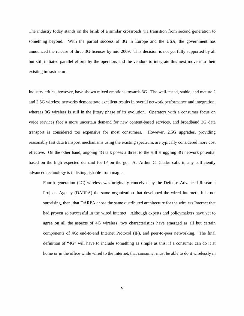
The industry today stands on the brink of a similar crossroads via transition from second generation to
something beyond. With the partial success of 3G in Europe and the USA, the government has
announced the release of three 3G licenses by mid 2009. This decision is not yet fully supported by all
but still initiated parallel efforts by the operators and the vendors to integrate this next move into their
existing infrastructure.
Industry critics, however, have shown mixed emotions towards 3G. The well-tested, stable, and mature 2
and 2.5G wireless networks demonstrate excellent results in overall network performance and integration,
whereas 3G wireless is still in the jittery phase of its evolution. Operators with a consumer focus on
voice services face a more uncertain demand for new content-based services, and broadband 3G data
transport is considered too expensive for most consumers. However, 2.5G upgrades, providing
reasonably fast data transport mechanisms using the existing spectrum, are typically considered more cost
effective. On the other hand, ongoing 4G talk poses a threat to the still struggling 3G network potential
based on the high expected demand for IP on the go. As Arthur C. Clarke calls it, any sufficiently
advanced technology is indistinguishable from magic.
Fourth generation (4G) wireless was originally conceived by the Defense Advanced Research
Projects Agency (DARPA) the same organization that developed the wired Internet. It is not
surprising, then, that DARPA chose the same distributed architecture for the wireless Internet that
had proven so successful in the wired Internet. Although experts and policymakers have yet to
agree on all the aspects of 4G wireless, two characteristics have emerged as all but certain
components of 4G: end-to-end Internet Protocol (IP), and peer-to-peer networking. The final
definition of “4G” will have to include something as simple as this: if a consumer can do it at
home or in the office while wired to the Internet, that consumer must be able to do it wirelessly in
vi
a fully mobile environment. Hence, sometimes referred to as, wireless ad hoc peer-to-peer
networking.1
Thus, the decision faced by Pakistan’s telecommunication industry today is tricky and challenging. It is
tricky because today the stakes have risen beyond mere following the footsteps of another region; with
progress and development of the industry have emerged new market trends and better consumer
awareness. It is challenging because with 4G evolving in parallel to 3G, stakeholders propose two
arguments: first, the high investment in the 2.5G networks has yet to provide the desired revenue that
would encourage future long-term investments by the financers and second, 3G is not a guaranteed
success due to the lingering shadows of 4G and its potential to become a reality as 4G proves itself in the
market.
Innovation and progress are indeed catalysts that trigger change and change in this case may be an
upgrade, evolution or revolution in technology. The question of which technology and where or how is
still unanswered. Some of the most important issues include market readiness, business issues (e.g.,
pricing, market segmentation), service issues (e.g., coverage, service portfolio, and QoS), and technical
challenges (e.g., spectrum availability, maturity of technology, and availability of proper user terminals).
This thesis will interpret such issues in regards to the expected transition in Pakistan and will justify a
migration model highlighting the inevitable challenges lining up for the region’s future.
1 Mobile Streams. “YES 2 3G” - White Paper. February 2001. www.mobile3G.com
vii
Acknowledgments
The author wishes to express sincere appreciation to Professor Ronald Fulle for his guidance and time in
the preparation of this manuscript. The core idea for this research originated from his teachings and
views. In addition, special thanks to Shehzad Khattak (Nokia Seimens network, Islamabad, Pakistan) and
Abid Riaz (BSS and TXN Implementation – North, Pakistan) for their insightful help with
telecommunication industry today in Pakistan. Thanks also to the members of RIT Libraries and RIT
publishing and research center for their valuable input.
viii
Table of Contents
Chapter 1 - Mobile Wireless Communication Evolution ............................................................... 1
1.1 Basics of Mobile Telephony ................................................................................................. 2
1.1.1 Basic Network Architecture ........................................................................................... 2
1.1.2 Cell and Sectors ............................................................................................................. 3
1.1.3 Air Interface Access Techniques ................................................................................... 4
1.1.4 Roaming ......................................................................................................................... 5
1.1.5 Handoff/Handover ......................................................................................................... 6
1.2 First Generation of Mobile Communication “1G” ............................................................... 6
1.2.1 Types .............................................................................................................................. 6
1.2.2 Limitations ..................................................................................................................... 7
1.3 Second Generation of Mobile Communication “2G” ........................................................... 7
1.3.1 Types .............................................................................................................................. 8
1.3.2 Limitations ..................................................................................................................... 9
Chapter 2 - Third Generation of Mobile Communication “3G” ................................................... 11
2.1 IMT-2000 ............................................................................................................................ 12
2.2 Radio Spectrum ................................................................................................................... 14
2.3 3G Standardization.............................................................................................................. 15
2.4 The Myth ............................................................................................................................. 16
2.5 Technologies ....................................................................................................................... 17
2.6 Revolution ........................................................................................................................... 18
2.6.1 UMTS Network Architecture ...................................................................................... 19
Access network (UTRAN) ................................................................................................ 19
Radio Network Controller............................................................................................. 21
Node B .......................................................................................................................... 21
ix
User equipment ................................................................................................................. 21
Core Network .................................................................................................................... 22
UMTS interfaces ............................................................................................................... 22
2.6.2 UMTS Air Interface ..................................................................................................... 23
Modulation ........................................................................................................................ 23
Spreading Factor ............................................................................................................... 24
Uplink ............................................................................................................................... 25
Downlink........................................................................................................................... 26
2.6.3 UMTS Services ............................................................................................................ 27
2.6.4 Traffic Types ................................................................................................................ 27
1. Conversational ........................................................................................................ 28
2. Interactive ............................................................................................................... 28
3. Streaming ................................................................................................................ 28
4. Background ............................................................................................................. 28
2.6.5 QoS in UMTS .............................................................................................................. 28
QoS Handling in the UMTS Core Network ...................................................................... 29
QoS Handling in the UMTS Terrestrial Radio Access Network ...................................... 30
2.6.6 Hand Over .................................................................................................................... 31
Hard Handover .................................................................................................................. 31
Soft Handover ................................................................................................................... 32
Softer Handover ................................................................................................................ 32
Inter-system handover ....................................................................................................... 33
2.7 Evolution (IMT-SC/EDGE) ................................................................................................ 34
2.7.1 GERAN Architecture ............................................................................................... 35
GERAN Interfaces ........................................................................................................ 35
2.7.2 GERAN Radio Protocols ......................................................................................... 37
2.7.3 Quality of Service .................................................................................................... 38
2.7.4 Services and Traffic types ........................................................................................ 38
2.7.5 Hand Over ................................................................................................................ 38
2.7.6 Air Interface ............................................................................................................. 39
Air Interface Coding Schemes and Data Rates ............................................................. 39
x
2.7.7 GERAN Evolution .................................................................................................. 40
EGPRS-2 ........................................................................................................................... 41
Downlink Dual Carrier ..................................................................................................... 42
MSRD via Dual Antenna Interference Cancellation (DAIC) ........................................... 42
Functionality to reduce latency times ............................................................................... 43
Data Rates ......................................................................................................................... 44
Chapter 3 - Beyond 3G ................................................................................................................. 46
3.1 High Speed Packet Access (HSPA) .................................................................................... 46
High Speed Downlink Packet Access (HSDPA) .................................................................. 46
High Speed Uplink Packet Access (HSUPA) ....................................................................... 47
3.2 HSPA+ ................................................................................................................................ 48
3.3 Long Term Evolution (LTE) ............................................................................................... 49
3.3.1 Evolved Packet System (EPS) Architecture ................................................................ 50
Interfaces and Protocols .................................................................................................... 52
3.3.2 Evolved UTRAN ......................................................................................................... 53
Access Scheme.................................................................................................................. 55
LTE Downlink Transmission Scheme OFDMA........................................................... 55
LTE Uplink Transmission Scheme SC-FDMA ............................................................ 57
LTE MIMO Concepts ....................................................................................................... 58
Downlink MIMO .......................................................................................................... 59
Uplink MIMO ............................................................................................................... 60
Spectrum flexibility .......................................................................................................... 60
The role of IMS ................................................................................................................. 61
3.4 4G ........................................................................................................................................ 62
Chapter 4 - Market and Consumer ................................................................................................ 64
4.1 Pakistan Mobile Market ...................................................................................................... 64
4.1.1 Market Share ................................................................................................................ 65
4.1.2 Foreign Investments ..................................................................................................... 65
4.1.3 Handset Market ............................................................................................................ 65
4.2 The Internet ......................................................................................................................... 66
4.3 Business environments in Pakistan ..................................................................................... 67

xi
4.3.1 Pakistan among top 20 outsorucing Detonations ......................................................... 69
4.4 3G Market and Consumer ................................................................................................... 70
4.4.1 Consumer Revolution in the Urban Areas ................................................................... 71
Audio................................................................................................................................. 71
VoIP .................................................................................................................................. 71
Still Images ....................................................................................................................... 71
Moving Images ................................................................................................................. 72
Virtual Home Environment............................................................................................... 72
Electronic Agent ............................................................................................................... 72
Downloading Software ..................................................................................................... 72
4.4.2 Consumer Revolution in the Rural Areas .................................................................... 73
Mobiles and Healthcare: Telehealth and Telemedicine Trends ........................................ 73
Improved Quality of Education ........................................................................................ 75
Distance Learning ............................................................................................................. 77
4.4.3 Applications Impact ..................................................................................................... 78
4.5 Future Forecast of Mobile Users..................................................................................... 78
Chapter 5 Regulation .................................................................................................................... 80
5.1 Regulation Enabling the Business Environment................................................................. 80
5.2 Pakistan Telecommunication Authority ............................................................................. 80
5.3 3G Licenses ................................................................................................................... 81
5.4 Issues Regarding 3G Licenses ...................................................................................... 82
5.4.1 MoITT .......................................................................................................................... 82
5.4.2 LTE .............................................................................................................................. 83
5.5 UMTS900 ........................................................................................................................... 83
5.5. 1 UMTS900 Technical Specifications ........................................................................... 84
5.5.2 UMTS900 Benefits ...................................................................................................... 84
Chapter 6 - Issues and Challenges ................................................................................................ 87
6.1 3G Issues and Challenges in Pakistan ............................................................................. 88
6.1.1 Regulatory .................................................................................................................... 88
6.1.2 Market and Consumer .................................................................................................. 89
6.1.3 Technology ...................................................................................................................... 90
xii
Chapter 7 Transition Model .......................................................................................................... 92
7.1 Model Guidelines ................................................................................................................ 92
7.2 Wireless Migration from an Operator’s Perspective .......................................................... 94
7.3 Wireless Migration from a Consumer’s perspective .......................................................... 95
7.4 3G Snapshot ........................................................................................................................ 96
7.4.1 Mobile Broadband Frequency...................................................................................... 96
7.4.2 Mobile Broadband Update ........................................................................................... 97
7.4.3 3G Radio Access Evolution ......................................................................................... 98
7.4.4 3G Cost, Data Rates and Delays .................................................................................. 98
7.4.5 3G handset market ..................................................................................................... 101
7.5 Migration Model ............................................................................................................... 102
7.5.1 Evolution-Evolved EDGE ............................................................................................. 102
7.5.2 What will the user experience be like? ...................................................................... 104
7.5.3 What will the network gains be? ................................................................................ 104
7.5.4 Market and Commercial Standing ............................................................................. 105
Evolution ............................................................................................................................. 105
7.6 Revolution ......................................................................................................................... 106
7.6.1 LTE ............................................................................................................................ 106
LTE in the long run ......................................................................................................... 107
7.6.2 UMTS ........................................................................................................................ 108
UMTS900 Finland .......................................................................................................... 109
UMTS900 Operator Case - Optus, Australia .................................................................. 112
Options to refarm 900 MHz for UMTS900 - while maintaining the GSM quality ........ 112
UMTS900 Commercialization ........................................................................................ 113
PTA Approvals ............................................................................................................... 113
7.7 Concluding Remarks ......................................................................................................... 114
Bibliography ............................................................................................................................... 117
References ................................................................................................................................... 118
White Papers ........................................................................................................................... 118
Books ...................................................................................................................................... 119
Internet links ........................................................................................................................... 119

xiii
Glossary ...................................................................................................................................... 120
Acronym List .......................................................................................................................... 120
Abbreviations .......................................................................................................................... 123
xiv
List of Figures
FIGURE 1 BASIC NETWORK ARCHITECTURE .............................................................................................................................. 3
FIGURE 2 ACCESS TECHNOLOGIES .......................................................................................................................................... 5
FIGURE 3 FDMA USED IN 1G ............................................................................................................................................... 7
FIGURE 4 AIR INTERFACE IN 2G ............................................................................................................................................. 8
FIGURE 5 3G VISION ......................................................................................................................................................... 12
FIGURE 6 IMT-2000 MOBILE/TERRESTRIAL RADIO INTERFACE STANDARDS ................................................................................. 13
FIGURE 7 MIGRATION POSSIBILITIES ..................................................................................................................................... 17
FIGURE 8 UMTS ARCHITECTURE ........................................................................................................................................ 20
FIGURE 9 UTRAN ARCHITECTURE....................................................................................................................................... 20
FIGURE 10 CDMA BASIC CONCEPT..................................................................................................................................... 24
FIGURE 11 UPLINK DATA RATES .......................................................................................................................................... 25
FIGURE 12 DOWNLINK DATA RATES .................................................................................................................................... 26
FIGURE 13 UMTS QOS ARCHITECTURE ................................................................................................................................ 29
FIGURE 14 RAB SERVICE ESTABLISHMENT PRINCIPLES ........................................................................................................... 31
FIGURE 15 SOFT AND SOFTER HANDOVER ............................................................................................................................ 33
FIGURE 16 INTER SYSTEM HAND OVER ................................................................................................................................. 34
FIGURE 17 GERAN ARCHITECTURE..................................................................................................................................... 35
FIGURE 18 UTRAN/ GERAN PROTOCOL MODEL .................................................................................................................. 36
FIGURE 19 MODULATION AND DATA RATES .......................................................................................................................... 40
FIGURE 20 PREDICTED USER THROUGHPUT ........................................................................................................................... 45
FIGURE 21 HSPA DATA RATES ........................................................................................................................................... 48
FIGURE 23 DETAILED EPS ARCHITECTURE VIEW ...................................................................................................................... 50
FIGURE 24 FREQUENCY-TIME REPRESENTATION OF AN OFDM SIGNAL ...................................................................................... 56
FIGURE 25 PHYSICAL LAYER REQUIREMENTS FOR LTE E-UTRAN ............................................................................................... 58
FIGURE 26 A PICTURE WORTH A THOUSAND WORDS IN UNDERSTANDING THE VISION OF 4G .......................................................... 63
FIGURE 27 PAKISTAN MOBILE MARKET ................................................................................................................................ 65
FIGURE 28 MOBILE HANDSET MARKET ................................................................................................................................. 66
FIGURE 29 INTERNET USAGE IN PAKISTAN ............................................................................................................................. 67
FIGURE 30 BMI RANKINGS ................................................................................................................................................ 69
FIGURE 31 TELE HEALTH .................................................................................................................................................. 75
FIGURE 32 EDUCATION IN REMOTE SECTORS .......................................................................................................................... 76
FIGURE 33 WIRELESS STATISTICS ........................................................................................................................................ 78
FIGURE 34 GSA MARKET SURVEY ........................................................................................................................................ 90
FIGURE 35 MOBILE BROADBAND FREQUENCY BANDS .............................................................................................................. 96
FIGURE 36 3G INTERNATIONAL MARKET STATS ...................................................................................................................... 97
FIGURE 37 3G EVOLUTION ................................................................................................................................................. 98
FIGURE 38 DATA RATES ..................................................................................................................................................... 99
FIGURE 39 COST PER TECHNOLOGY ...................................................................................................................................... 99
FIGURE 40 THE EVOLUTION PATH FOR 3G ........................................................................................................................... 100
FIGURE 41 3G HANDSET INDUSTRY .................................................................................................................................... 101
FIGURE 42 DATA RATES FOR VARIOUS SERVICES .................................................................................................................... 103
FIGURE 43 EVOLVED EDGE DATA RATES ............................................................................................................................... 104
FIGURE 44 OPERATOR COST OF OWNERSHIP ........................................................................................................................ 106

xv
FIGURE 45 ELISA TRAFFIC GROWTH CHART ........................................................................................................................... 109
FIGURE 46 REDUCTION IN CAPEX AND OPEX ........................................................................................................................ 111
FIGURE 47 UMTS900 GLOBAL STATUS ............................................................................................................................. 114

[3G Migration in Pakistan]
1
Chapter 1 - Mobile Wireless Communication Evolution
“Mobile telephony dates back to 1920s, with the partial success with maritime vessel. Due to extremely
bulky equipment and lack of sophisticated radio technology, it was not particularly suited to on-land
communication. Further progress was made during the Second World War in the 1930s with the
development of frequency modulation (FM). Developments were carried over to peacetime enabling
limited mobile telephony service in the 1940s in some large cities.”2
The first radiotelephone service was introduced in the US at the end of the 1940s, and was meant
to connect mobile users in cars to the public fixed network. In the 1960s, a new system launched
by Bell Systems, called “Improved Mobile Telephone Service” (IMTS), brought many
improvements like direct dialing and higher bandwidth. The first analog cellular systems were
based on IMTS and developed in the late 1960s and early 1970s. The systems were “cellular”
because coverage areas were split into smaller areas or “cells”, each of which is served by a low
power transmitter and receiver.3
“Until the advent of IMT-2000, discussed later in detail, cellular networks had been developed under a
number of proprietary, regional and national standards, creating a fragmented market.”4
2 Smith, Clint, P.E. 3G wireless networks. New York : McGraw-Hill, c2007.
3 Source: ITU http://www.itu.int/osg/spu/ni/3G/technology/
4 Source- ITU http://www.itu.int/osg/spu/ni/3G/technology/
[3G Migration in Pakistan]
2
1.1 Basics of Mobile Telephony
It is crucial to highlight some basic concepts in mobile telephony in order to provide grounds for building
and understanding the ideas discussed hereafter. Model used is 2G since it provides ground for 3G
evolution.
1.1.1 Basic Network Architecture
1. BSC: A number of base stations are connected to and controlled by a Base Station Controller
(BSC) with the control logic embedded in the BSC. Among other tasks, the BSC manages the
handoff of calls from one base station to another as subscribers move from cell to cell.
2. MSC: Connected to the BSC is the Mobile Switching Center (MSC), a switch that manages the
set up and teardown of calls to and from mobile subscribers. In addition to numerous similarities
with standard PSTN switch, it contains a number of functions that are specific to mobile
communications. For example, it interacts with a number of BSCs over an interface, contains
logic of its own to deal with mobile subscribers, and part of this logic involves an interface to one
or more HLRs.
3. HLR: Effectively a subscriber database, home location register (HLR) contains subscription
information related to a number of subscribers. It plays a critical role in mobility management,
the tracking of a subscriber as he or she moves around the network. “As a subscriber moves from
one MSC to another, each MSC in turn notifies the HLR. When a call is received from the
PSTN, the MSC that receives the call queries the HLR for the latest information regarding the
subscriber location so that the call could be correctly routed to the subscriber.5
5 Source-ITU http://www.itu.int/osg/spu/ni/3G/technology/

[3G Migration in Pakistan]
3
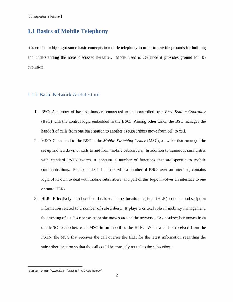
Figure 1 Basic Network Architecture
The network depicted in figure 4 can be considered as representing the bare minimum needed to provide a
mobile telephony service. In addition, there are VLR and IN systems that deal with visiting subscribers
and network intelligence (authentication, security, billing, etc.) respectively.
1.1.2 Cell and Sectors
The concept of cellular mobile telephony was the breakthrough that caused mobile telephony to become
something viable. “Before the advent of cellular technology, capacity was enhanced through a division of
frequencies and the resulting addition of available channels. However, this reduced the total bandwidth
available to each user, affecting the quality of service. Cellular technology allowed for the division of
geographical areas, rather than frequencies, leading to a more efficient use of the radio spectrum. This
geographical re-use of radio channels is known as “frequency reuse.”6
6 Source-ITU http://www.itu.int/osg/spu/ni/3G/technology/

[3G Migration in Pakistan]
4
1.1.3 Air Interface Access Techniques
“Radio spectrum is a precious and finite resource. Unlike other transmission media such as copper or
fiber facilities, it is not possible to simply add radio spectrum when needed. Only a certain amount of
spectrum is available and it is critical that it be used efficiently, and be reused as much as possible. Such
requirements are at the heart of the radio access techniques used in mobile communications.”7
FDMA: Frequency Division Multiple Access (FMDA) chunks up available spectrum into predefined
bandwidths and then assigns one to each user. The result is a scenario where the network has one user per
band of frequency or per channel as shown in figure 1. The channel, therefore, is closed to other
conversations until the initial call is finished or until it is handed off to a different channel. “In most
FDMA systems, separate channels are used in each direction one from network to subscriber (downlink)
and the other from subscriber to network (uplink). For example, in analog AMPS 30-kHz channels
implies two 30-kHz channels, one in each direction. Such an approach is known as Frequency Division
Duplex (FDD) and normally a fixed separation exists between the frequency used in the uplink and that
used in the downlink. This fixed separation is known as the duplex distance.”8
TDMA: “Time Division Multiple Access (TDMA) improves spectrum capacity by splitting each
frequency into time slots. TDMA allows each user to access the entire radio frequency channel for the
short period of a call. Other users share this same frequency channel at different time slots. The base
station continually switches from user to user on the channel. TDMA is the dominant technology for the
second generation mobile cellular networks.”9
7 Smith, Clint, P.E. 3G wireless networks. New York : McGraw-Hill, c2007.
8 Smith, Clint, P.E. 3G wireless networks. New York : McGraw-Hill, c2007.
9 Source ITU http://www.itu.int/osg/spu/ni/3G/technology/

[3G Migration in Pakistan]
5
CDMA: Originating from the spread spectrum technology which involves spreading the signal over a
wide bandwidth, Code Division Multiple Access (CDMA) increases spectrum capacity by allocating the
entire radio band to all users in a given instant of time. User communication (voice and data) is identified
based on a unique code assigned to individual user. “CDMA allows for a ‘soft hand-off,’ which means
that terminals can communicate with several base stations at the same time.”10
Figure 2 Access Technologies
1.1.4 Roaming
Roaming converts a wireless communication network into a mobile network. “Mobility implies that
subscribers be able to move freely around the network and from one network to another. This requires
that the network tracks the location of a subscriber to certain accuracy so that calls destined for the
subscriber may be delivered and allow him to do so while engaged in a call.”11
10 Source ITU http://www.itu.int/osg/spu/ni/3G/technology/ 11 Smith, Clint, P.E. 3G wireless networks. New York : McGraw-Hill, c2007.

[3G Migration in Pakistan]
6
1.1.5 Handoff/Handover
Defined as the ability of a subscriber to maintain a call while moving within the network, handoff implies
that a subscriber travels from one cell to another while engaged in a call, and that call is maintained
during the transition (ideally without the subscriber noticing any change). Depending on the two cells in
question, the handoff can be between two sectors on the same base station, between two channels within
the same cell, between two BSCs, between two MSCs belonging to the same operator, or even between
two networks.
1.2 First Generation of Mobile Communication “1G”
1.2.1 Types
Based purely on analog communication, 1G marked the advent of wireless communication. The three
major 1G technologies that gained popularity are:
1. AMPS: It began with the implementation of a trial system in Chicago in 1978 using a technology
known as Advanced Mobile Phone Service (AMPS), operating in the 800-MHz band based on
FDMA. For numerous reasons, however, including the break-up of AT&T, it took a few years
before a commercial system was launched in the United States in 1983, with other cities
following rapidly.
2. NMT: The Europeans 1G systems were launched in 1981 in Sweden, Norway, Denmark, and
Finland using a technology known as Nordic Mobile Telephony (NMT), operating in the 450-
MHz band. Later, another version was developed to operate in the 900-MHz band and was
known as NMT900.

[3G Migration in Pakistan]
7
3. TACS: Britian introduced a modified version of AMPS in 1985 called the Total Access
Communications System (TACS) that operated 900-MHz band.
1.2.2 Limitations
The success of 1G was beyond what anyone had expected. It was this very success that eventually
exposed shortcomings like limited capacity and vulnerability to fraud. “The systems were able to handle
large numbers of subscribers, but when the subscribers started to number in the millions, cracks started to
appear, particularly since subscribers tend to be densely clustered in metropolitan areas. Consequently,
significant effort was dedicated to the development of second-generation systems.”12
Figure 3 FDMA used in 1G
1.3 Second Generation of Mobile Communication “2G”
Formally known as the digital cellular networks, 2G systems were first developed at the end of the 1980s.
Primary reason behind 2G was to increase network’s voice call capacity by enabling more calls within a
cell. The call capacity within a cell increases by using TDMA rather than FDMA. The 200 KHz
frequency band is divided into channels, where each channel is shared among eight users by time slots,
12
Smith, Clint, P.E. 3G wireless networks. New York : McGraw-Hill, c2007.

[3G Migration in Pakistan]
8
one for each user. Each user could send a burst of bearer data within that one time slot assigned uniquely
to him or her. These systems digitized not only the control link but also the voice signal and provided
better quality and higher capacity at lower cost to consumers. The approach involves compressing the
voice signal digitally and then doing modulation. Result is a significant change in the core network
(introduction of the concept of intelligent network). “Intelligent Network (IN) is a telephone network
architecture in which the service logic for a call is located separately from the switching facilities,
allowing services to be added or changed without having to redesign switching equipment.”13
Figure 4 Air Interface in 2G
“Using FDMA, the available bandwidth is divided into a number of smaller channels as in FDMA and it
is these channels that are divided into timeslots. The difference between a pure FDMA system and a
TDMA system that also uses FDMA is that, with the TDMA system, a given user does not have exclusive
access to the radio channel.”14
1.3.1 Types
Based on digital communication both in radio path and between the network entities, these systems
brought semi-global acceptance, and consequently roaming, to large regions.
1. Global system for Mobile Communication (GSM): Developed by ETSI, the most popular 2G
standard surfaced in 1989. Early version used 25MHz frequency spectrum in the 900 MHz band.
13 http://searchnetworking.techtarget.com/sDefinition/0,,sid7_gci212335,00.html 14
Smith, Clint, P.E. 3G wireless networks. New York : McGraw-Hill, c2007.
[3G Migration in Pakistan]
9
This 25MHz was further divided into 124 carrier channels of 200 KHz each. A single 200 KHz
channel was then used among eight users via TDMA. Of late, there are two other variants of
GSM operating at 1.8 GHz and 1.9 GHz.
2. Personal Digital Communication (PDC): Immensely popular in Japan, this 2G technology works
at 800 MHz and 1500 MHz frequencies. Since PDC success was limited to Japan, it is no
surprise that Japan was the first one to launch a 3G network in 2001 in an attempt to work toward
a 3G technology that was globally accepted.
3. IS-95: While most of the 2G technologies were based on FDMA and TDMA, Qualcomm
designed a code division multiple access scheme. This scheme uses separate code to distinguish
between data transmitted by different users on the same frequency.
4. US-TDMA or D-AMPS: Popular in North America, this was a digital version of First Generation
AMPS technology.
5. Personal Handy Phone System (PHS): Somewhere in between a cellular and a cordless
technology, it was a cheaper alternative to cellular systems used in Japan.15
1.3.2 Limitations
2G brought a major change in the way mobile networks were built, but they had their limitations:
1. Lower transfer rate: Designed primarily for voice services, the data transfer rate offered was low.
Though the rates vary across technologies, the average rate is in the order to tens of kilobits per
second.
2. Low efficiency for packet-switched services: With the immense popularity of the Internet came
the demand among customers for access to the Internet while on the go. Wireless Internet access
with the 2G networks is not efficiently implemented.
15 3G Mobile Networks- Architecture, Protocol, and Procedures
[3G Migration in Pakistan]
10
3. Multiple Standards: A multitude of competing standards allowed a user limited roaming; it was
possible in regions that supported same technology. The 2G standards were semi- global and
failed to allow global roaming.16
A series of standards, termed 2.5G, were developed later on to deal with the slow data rate issue. These
standards were HSCSD - High speed Circuit-Switched Data (data rate of 57.6 Kbps), GPRS - General
packet radio service (data rate of 115Kbps), and EDGE - Enhanced data rate for Global Evolution
(384Kbps).
16
3G Mobile Networks- Architecture, Protocol, and Procedures

[3G Migration in Pakistan]
11
Chapter 2 - Third Generation of Mobile Communication “3G”
The mobile world of 2G, in spite of the increased data rates through 2.5G technologies, failed to cope
with the huge demand for mobile broadband services, especially Internet. Internet access anywhere
anytime!
3G talk started at ITU and in Europe as early as 1992, a year after 2G was commercially launched. “ITU,
in the late 1990’s, saw the growth of the Internet and other packet data applications as the key to
developing third generation cellular systems.”17 The vision, initially known as Future Public Land Mobile
Telecommunication System (FLMTS), “was to have a high data rate-globally accepted technology (3G)
to indicate the next generation of mobile services capabilities in terms of bandwidth and network
functions. These service capabilities in turn allow advanced services and applications, including
multimedia.”18 It talked about having cells (Micro, Macro, and Pico) at many different scales with
varying coverage areas. All were all to register under the umbrella of one standard.
Third generation (3G) systems promise faster communications services, including voice, fax and
Internet, anytime and anywhere with seamless global roaming. ITU’s IMT-2000 global standard for 3G
has opened the way to enabling innovative applications and services such as multimedia entertainment,
infotainment and location-based services, among others. 3G is the term used to describe the latest
generation of mobile technology which provides enhancements to voice communications and data
connectivity including wireless access to the Internet, mobile applications and multimedia content.19
17
Wireless communications : evolution to 3G and beyond 18
3G Mobile Networks- Architecture, Protocol, and Procedures 19
A White Paper from the UMTS Forum Mobile Broadband Evolution: the roadmap from HSPA to LTE February 2009
[3G Migration in Pakistan]
12
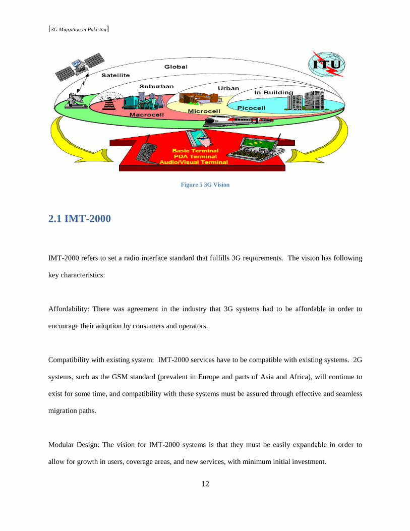
Figure 5 3G Vision
2.1 IMT-2000
IMT-2000 refers to set a radio interface standard that fulfills 3G requirements. The vision has following
key characteristics:
Affordability: There was agreement in the industry that 3G systems had to be affordable in order to
encourage their adoption by consumers and operators.
Compatibility with existing system: IMT-2000 services have to be compatible with existing systems. 2G
systems, such as the GSM standard (prevalent in Europe and parts of Asia and Africa), will continue to
exist for some time, and compatibility with these systems must be assured through effective and seamless
migration paths.
Modular Design: The vision for IMT-2000 systems is that they must be easily expandable in order to
allow for growth in users, coverage areas, and new services, with minimum initial investment.

[3G Migration in Pakistan]
13
Flexibility: With the large number of mergers and consolidations occurring in the mobile industry and the
move into foreign markets, operators wanted to avoid having to support a wide range of different
interfaces and technologies. This problem was addressed by providing a highly flexible system capable
of supporting a wide range of services and applications. The IMT-2000 standard accommodates five
possible radio interfaces based on three different access technologies (FDMA, TDMA and CDMA): 20
Figure 6 IMT-2000 mobile/terrestrial radio interface standards
IMT-Direct Spread (IMT-DS): CDMA direct spread is known as WCDMA and is intended for
applications in public macro cell and microcell environments.
IMT-Multicarrier (IMT-MC) refers to CDMA2000 1X and CDMA20001xEV.
IMT-Time Code (IMT-TC) is a combination of WCDMA-TDD and TD-SCDMA.
IMT-Single Carrier (IMT-SC) corresponds to Universal Wireless Communication 136 and EDGE.
IMT-Frequency Time (IMT-FT) is the European digital enhanced cordless telecommunication proposal
(DECT).
20 www.itu.int/osg/spu/imt-2000/technology.html

[3G Migration in Pakistan]
14
“IMT-2000 is the result of collaboration of many entities, inside the ITU (ITU-R) and (ITU-T) and
outside the ITU (3GPP, 3GPP2, UWCC and so on) in an effort to attain full interoperability and
interworking of mobile systems.” 21 “The IMT-2000 specification is meant to be a unifying specification,
enabling mobile and some fixed high-speed data services to use one or several radio channels with fixed
network platforms for delivering the services envisioned:
a) Global standard, b) Compatibility of service within IMT-2000 and other fixed networks, c) High
quality, d) Worldwide common frequency band, e) Small terminals for worldwide use, f) Worldwide
roaming capability, g) Multimedia application services and terminals, h) Improved spectrum efficiency, i)
Flexibility for evolution to the next generation of wireless systems, j) High-speed packet data rates, k) 2
Mbps for fixed environment, 384 kbps for pedestrian, 144 Kbps for vehicular traffic.” 22
2.2 Radio Spectrum
Mobile operators use radio spectrum to provide their services. Spectrum in the cellular world is a scarce
resource and is allocated as such. IMT-2000 vision necessitated finding a new globally available
frequency band as well as maximizing convergence within the many existing 2G wireless technologies.
At the 1992 ITU World Radio Conference, 230 MHz of new radio spectrum was identified. At
WRC2000, spectrum capacity expanded significantly by allowing the use of current 2G spectrum blocks
for 3G technology and allocating 3G spectrum to an upper limit of 3GHz. The result was a threefold
increase in the potential IMT-2000 spectrum. The 2007 World Radio Conference made valuable strides
in identifying additional spectrum for IMT, both below 1GHz and above 2 GHz. The following
frequency bands are currently identified for IMT: (Band 1) 450 – 470 MHz, (Band 2) 790 – 960 MHz,
21
http://www.itu.int/home/imt.html 22
3G wireless networks

[3G Migration in Pakistan]
15
(Band 3) 1710 – 2025 MHz, (Band 4) 2110 – 2200 MHz, (Band 5) 2300 – 2400 MHz, (Band 6) 2500 –
2690 MHz23
2.3 3G Standardization
The idea of one global standard for 3G was hard to apply due to the rapid growth of 2G mobile during the
1990’s. With several similar technologies worldwide, it became necessary for ITU to offer a number of
possible routes from the various existing 2G systems to a 3G capability. This led to the establishment of
two distinct 3G families:
3GPP2: 3rd Generation Partnership Project 2 (3GPP2) was formed to help North American and Asian
operators using CDMA2000 transition to 3G. 3GPP2 technologies evolved as 1XRTT, EV-DO, EV-DO
Rev. A, EV-DO Rev. B and UMB.
3GPP: The 3rd Generation Partnership Project (3GPP) was formed to foster deployment of 3G networks
that descended from GSM. 3GPP technologies evolved as GPRS, EDGE, WCDMA, HSDPA, and LTE. 24
Note: GSM constitutes more than 95% of the cellular market in Pakistan (chapter x). Pakistan as the
focus of this research entails 3GPPstandards as a guideline for 3G migration.
23 http://www.itu.int/ITU-D/imt-2000/DocumentsIMT2000/Spectrum-IMT.pdf
24 http://searchtelecom.techtarget.com/sDefinition/0,,sid103_gci214486,00.html
[3G Migration in Pakistan]
16
2.4 The Myth
The frequency bands for IMT-2000 were allocated in two steps: WRC 1992 and WRC 2000. Spectrum
auction in late 1990’s was primarily for the newly defined high frequency bands. “Many country-specific
regulations controlled which IMT-2000 family option could be deployed. Result was media focus on the
‘revolutionary’ members of the IMT-2000 family of standards, which led to a belief that this was the only
real 3G. Many industry organizations only consider part of the IMT-2000 family of 3G standards as
actual 3G technologies; in particular IMT-SC (EDGE) is excluded from most 3G mobile statistics. This
is particularly unfortunate because IMT-SC is the ‘evolutionary’ option for the vast installed GSM (2G)
base and therefore will almost certainly become the dominant 3G component in the near future. IMT-SC
is typically excluded because many within the industry view CDMA as the only 3G wireless
technologies.”25
“The term 3G represents the next generation of mobile services. These services include better quality
voice, higher capacity access to the Internet and high speed packet data and multimedia applications. The
international 3G standards have been accepted by ITU under the name of IMT-2000”26. IMT-2000 offers
both evolution and revolution options for migration to 3G.
Evolution: Backwards compatible evolution of a 2G standard to its 3G equivalent within an operator’s
existing spectrum allocation. There are essentially two widely deployed “evolutionary” IMT-2000
standards: IMT-MC (cdma2000) and IMT-SC (EDGE).
25
http://www.itu.int/ITU-D/imt-2000/DocumentsIMT2000/What_really_3G.pdf 26
Wireless communications : evolution to 3G and beyond
[3G Migration in Pakistan]
17
Revolution: Required an operator to obtain additional spectrum, build an overlay network, and utilize dual
mode/band mobile equipment. These are MT-DS (W-CDMA) because of the relatively wide channels (5
MHz), and IMT-TC (TD-SCDMA/UTRA TDD) plus IMT-FT (DECT) because a TDD frequency
assignment is required. Note that it can in some cases be possible to deploy IMT-DS in existing cellular
bands if sufficient spare bandwidth can be made available.27
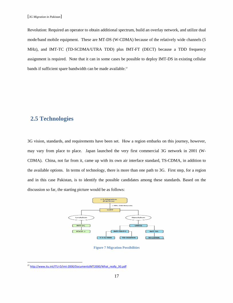
2.5 Technologies
3G vision, standards, and requirements have been set. How a region embarks on this journey, however,
may vary from place to place. Japan launched the very first commercial 3G network in 2001 (W-
CDMA). China, not far from it, came up with its own air interface standard, TS-CDMA, in addition to
the available options. In terms of technology, there is more than one path to 3G. First step, for a region
and in this case Pakistan, is to identify the possible candidates among these standards. Based on the
discussion so far, the starting picture would be as follows:
Figure 7 Migration Possibilities
27
http://www.itu.int/ITU-D/imt-2000/DocumentsIMT2000/What_really_3G.pdf
[3G Migration in Pakistan]
18
Note: IMT-MC and IMT-DT are eliminated due to fact that these technologies are irrelevant to discussion
at hand. IMT-MC is for 2G networks originating from IS-95 standard one, and IMT-DT is for the
European DECT.
2.6 Revolution
The options for revolution can all be categorized under the umbrella of Universal Mobile
Telecommunications System. UMTS is the term coined by 3GPP, synonymous to 3G networks, and
represents an evolution of GSM to support 3G capabilities. UMTS includes three of the air interfaces
from IMT-2000 standard list.
1. (Direct Sequence Wideband CDMA) WCDMA-FDD: In the FDD option, paired 5-MHz carriers
are used in the uplink and downlink as follows: uplink (1920 MHz to 1980 MHz); downlink
(2110 MHz to 2170 MHz). Thus, for the FDD mode of operation, a separation of 190 MHz is
used between the uplink and downlink.
2. (Direct Sequence Wideband CDMA) WCDMA-TDD: For TDD option, a number of frequencies
have been defined, including (1900 MHz to 1920 MHz) and (2010 MHz to 2025 MHz). Of
course, with TDD, a given carrier is used in both the uplink and the downlink so that no
separation exists.28
3. (Time Division Synchronous Code Division Multiple Access) TD-SCDMA: In the second release
of radio access interface for UMTS (UTRA), TD-SCDMA was included. Jointly developed by
Siemens and the China Academy of Telecommunications Technology (CATT), TDSCDMA 2010
28
3G wireless networks
[3G Migration in Pakistan]
19
MHz - 2025 MHz in China combines an advanced TDMA/TDD system with an adaptive CDMA
component operating in a synchronous mode.29
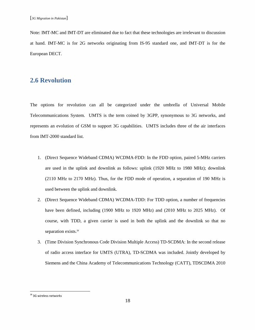
2.6.1 UMTS Network Architecture
The basic UMTS network bears similarities with any wireless network and is modeled along the lines of
GSM/GPRS. “The RNC in UMTS networks provides functions equivalent to the base station controller
(BSC) functions in GSM/GPRS networks. Node B in UMTS networks is equivalent to the base
transceiver station (BTS) in GSM/GPRS networks. In this way, the UMTS extends existing GSM and
GPRS networks, protecting the investment of mobile wireless operators. It enables new services over
existing interfaces such as A, Gb, and Abis, and new interfaces that include the UTRAN interface
between Node B and the RNC (Iub) and the UTRAN interface between two RNCs (Iur).”30 The network
may be partitioned into three broad entities.
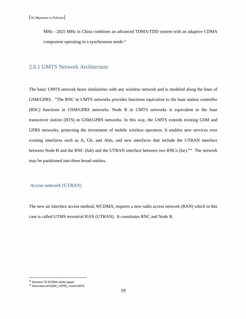
Access network (UTRAN)
The new air interface access method, WCDMA, requires a new radio access network (RAN) which in this
case is called UTMS terrestrial RAN (UTRAN). It constitutes RNC and Node B.
29
Siemens TD-SCDMA white paper 30 Overview+of+GSM_+GPRS_+and+UMTS
[3G Migration in Pakistan]
20
Figure 8 UMTS Architecture 31
Figure 9 UTRAN Architecture
31
www.nmscommunications.com
[3G Migration in Pakistan]
21
Radio Network Controller
“RNC functions include Radio resource control, Admission control, Channel allocation, Power control
settings, Handover control, Macro diversity, Ciphering, Segmentation and reassembly, Broadcast
signaling, and open loop power control.”32 The RNC that controls a given Node B is known as the
Controlling RNC (CRNC). The CRNC is responsible for the management of radio resources available at a
Node B that it supports. For a given connection between the UE and the core network, RNC is in control
and is called Serving RNC or SRNC. 33
Node B
Node B is the radio transmission/reception unit for communication between radio cells. Each Node B unit
can provide service for one or more cells. Node B connects to the user equipment (UE) over the Uu radio
interface using wide-band code division multiple access (WCDMA), supporting FDD and TDD. The
main function of Node B is conversion of data on the Uu radio interface. The functions of Node B
include air interface transmission and reception, modulation and demodulation, CDMA physical channel
coding, micro diversity, error handling, closed loop and power control.”34
User equipment
The UMTS user equipment (UE) is the combination of the subscriber’s mobile equipment and the
UMTS Subscriber identity module (USIM). The USIM card has the same physical characteristics
as the GSM/GPRS SIM card and provides functions like supports multiple user profiles on the
32
Overview+of+GSM_+GPRS_+and+UMTS 33
3G Wireless Networks 34
Overview+of+GSM_+GPRS_+and+UMTS
[3G Migration in Pakistan]
22
USIM, updates USIM information over the air provides security functions, provides user
authentication, supports inclusion of payment methods, supports secure downloading of new
applications, etc. The UMTS standard places no restrictions on the functions that the UE can
provide. Many of the identity types for UE devices are taken directly from GSM specifications;
such as International Mobile Subscriber Identity (IMSI) and Temporary Mobile Subscriber
Identity (TMSI).35
Core Network
The core network requires minor modifications to accommodate the UTRAN since it is based upon the
core from GSM. GSM core can support both UTRAN and GSM radio access. Logically, it can be divided
into packet and circuit switched domain. “Core functions include mobility management, call control,
switching, session management, routing, authentication and equipment identification.”36
UMTS interfaces
In comparison with the preceding 3GPP GSM architecture (GSM/GPRS), UMTS defines four new open
interfaces:
1. Uu interface—User equipment to Node B (the UMTS WCDMA air interface)
2. Iu interface—RNC to GSM/GPRS (MSC/VLR or SGSN)
Iu-CS—Interface for circuit-switched data
Iu-PS—Interface for packet-switched data
3. Iub interface—RNC to Node B interface
35
Overview+of+GSM_+GPRS_+and+UMTS 36
3G Mobile Networks- Architecture, Protocol, and Procedures
[3G Migration in Pakistan]
23
4. Iur interface—RNC to RNC interface (no equivalent in GSM).37
2.6.2 UMTS Air Interface
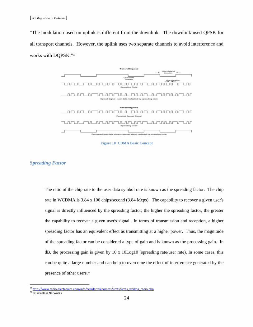
DS-CDMA means that user data is spread over a much wider bandwidth through multiplication
by a sequence of pseudo-random bits called chips. Figure 2.3 provides a conceptual depiction of
this spreading. The user data, at a relatively low rate compared to spreading code rate, is spread
over a signal that has a higher bit rate and the signal transmitted has pseudo-random
characteristics. When transmitted over a radio interface, the spread signal looks like noise. If
multiple users transmit simultaneously on the same frequency, then the stream of data from each
user needs to be spread according to a different pseudo-random sequence. At the receiving end,
the stream of data from a given user is recovered by dispreading the set of received signals with
the appropriate spreading code. What is being dispread is the complete set of signals received
from all users that are transmitting. As the number of simultaneous users increases, so does the
interference and it eventually becomes impossible to recover a specific user's data with any
confidence. In other words, for a given bit of recovered user data, the signal-to-noise ratio must
be sufficiently high. In CDMA, provided that Eb/No is sufficiently large, the user data can be
recovered.38
Modulation
37
Overview+of+GSM_+GPRS_+and+UMTS 38
3G Wireless Networks; Eb is the power density per bit of recovered user data and No is the noise power density.
[3G Migration in Pakistan]
24
“The modulation used on uplink is different from the downlink. The downlink used QPSK for
all transport channels. However, the uplink uses two separate channels to avoid interference and
works with DQPSK.”39
Figure 10 CDMA Basic Concept
Spreading Factor
The ratio of the chip rate to the user data symbol rate is known as the spreading factor. The chip
rate in WCDMA is 3.84 x 10⁶ chips/second (3.84 Mcps). The capability to recover a given user's
signal is directly influenced by the spreading factor; the higher the spreading factor, the greater
the capability to recover a given user's signal. In terms of transmission and reception, a higher
spreading factor has an equivalent effect as transmitting at a higher power. Thus, the magnitude
of the spreading factor can be considered a type of gain and is known as the processing gain. In
dB, the processing gain is given by 10 x 10Log10 (spreading rate/user rate). In some cases, this
can be quite a large number and can help to overcome the effect of interference generated by the
presence of other users.40
39
http://www.radio-electronics.com/info/cellulartelecomms/umts/umts_wcdma_radio.php 40
3G wireless Networks

[3G Migration in Pakistan]
25
Uplink
“In theory, for a speech service at 12.2 Kbps (and, for now, assuming no extra bandwidth for error
correction), the spreading factor would be 3.84 x 10⁶/12.2 x 103 = 314.75. This would equate to a
processing gain of 25 dB. In reality, however, WCDMA does include extra coding for error correction.
Consequently, a spreading factor as high as 314.75 is not supported, at least not in the uplink. The
supported uplink spreading factors are 4, 8, 16, 32, 64, 128, and 256. The highest spreading factor (256)
is used mostly by the various control channels. Some control channels can also use lower spreading
factors, while user services generally use lower spreading factors.”41 A summary of the spreading factors
and the corresponding data rates on the uplink is:
Figure 11 Uplink Data Rates
“The lowest spreading factor (4) provides a gross rate of only 960 Kbps and a usable rate of only 480
Kbps. This does not meet the requirements of IMT-2000, which states that a user should be able to
achieve speeds of 2 Mbps. In order to meet that requirement, UMTS supports the capability for a given
41
ibid
[3G Migration in Pakistan]
26
user to transmit up to six simultaneous data channels. Thus, if a user wants to transmit user data at a user
rate greater than 480 Kbps, then multiple channels are used, each with a spreading factor of four. With
six parallel channels, each at a spreading factor of four, a single user can obtain speeds of over 2 Mbps.”42
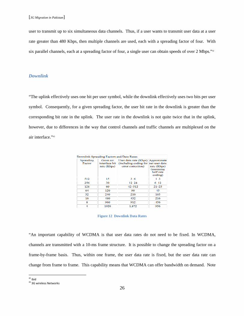
Downlink
“The uplink effectively uses one bit per user symbol, while the downlink effectively uses two bits per user
symbol. Consequently, for a given spreading factor, the user bit rate in the downlink is greater than the
corresponding bit rate in the uplink. The user rate in the downlink is not quite twice that in the uplink,
however, due to differences in the way that control channels and traffic channels are multiplexed on the
air interface.”43
Figure 12 Downlink Data Rates
“An important capability of WCDMA is that user data rates do not need to be fixed. In WCDMA,
channels are transmitted with a 10-ms frame structure. It is possible to change the spreading factor on a
frame-by-frame basis. Thus, within one frame, the user data rate is fixed, but the user data rate can
change from frame to frame. This capability means that WCDMA can offer bandwidth on demand. Note
42
ibid 43
3G wireless Networks

[3G Migration in Pakistan]
27
that rate changes every 10 ms do not apply to AMR speech as each speech packet is 20 ms in duration, so
that the speech rate can change every 20 ms if needed, but not every 10 ms.” 44
2.6.3 UMTS Services
The UMTS supports the following service categories and applications:
1. Internet access: Messaging, video/music download, voice/video over IP, mobile commerce (e.g.,
banking, trading), travel and information services.
2. Intranet/extranet access: Enterprise application such as e-mail/messaging, travel assistance,
mobile sales, technical services, corporate database access, fleet/warehouse management,
conferencing, and video telephony.
3. Customized information/entertainment: Information (photo/video/music download), travel
assistance, distance education, mobile messaging, gaming, voice portal services.
4. Multimedia messaging: SMS extensions for images, video, and music; unified messaging;
document transfer.
5. Location-based services: Yellow pages, mobile commerce, navigational service, trade.45
2.6.4 Traffic Types
UMTS promises high data rate capabilities, but there is more to a given service than just the data rate that
the service demands. UMTS specifications define four service classes, where the services within a given
class have a common set of characteristics. The service classes are as follows:
44
ibid 45
Overview+of+GSM_+GPRS_+and+UMTS
[3G Migration in Pakistan]
28
1. Conversational is characterized by low delay tolerance, low jitter (delay variation), and low
error tolerance. The data rate requirement may be high or low but is generally symmetrical.
Examples are Voice, video telephony, and video gaming.
2. Interactive consists of typically request/response-type transactions and is characterized by low
tolerance for errors but with a larger tolerance for delays than conversational services. Jitter
(delay variation) is not a major impediment to interactive services, provided that the overall delay
does not become excessive. Interactive services may require low or high data rates depending on
the service in question, but the data rate is generally significant only in one direction at a time.
Examples are Web browsing, network gaming, and database access.
3. Streaming concerns one-way services, using low- to high-bit rates. Streaming services have a
low-error tolerance but generally have a high tolerance for delay and jitter. That is because the
receiving application usually buffers data so that it can be played to the user in a synchronized
manner. Streaming audio and streaming video are typical streaming applications in addition to
Multimedia, video on demand, and webcast.
4. Background is characterized by little, if any, delay constraint. Examples include E-mail, short
message service (SMS), file downloading, server-to-server e-mail delivery (as opposed to user
retrieval of e-mail), and performance/measurement reporting. Background applications require
error-free delivery.46
2.6.5 QoS in UMTS
46
3G Wireless Networks
[3G Migration in Pakistan]
29
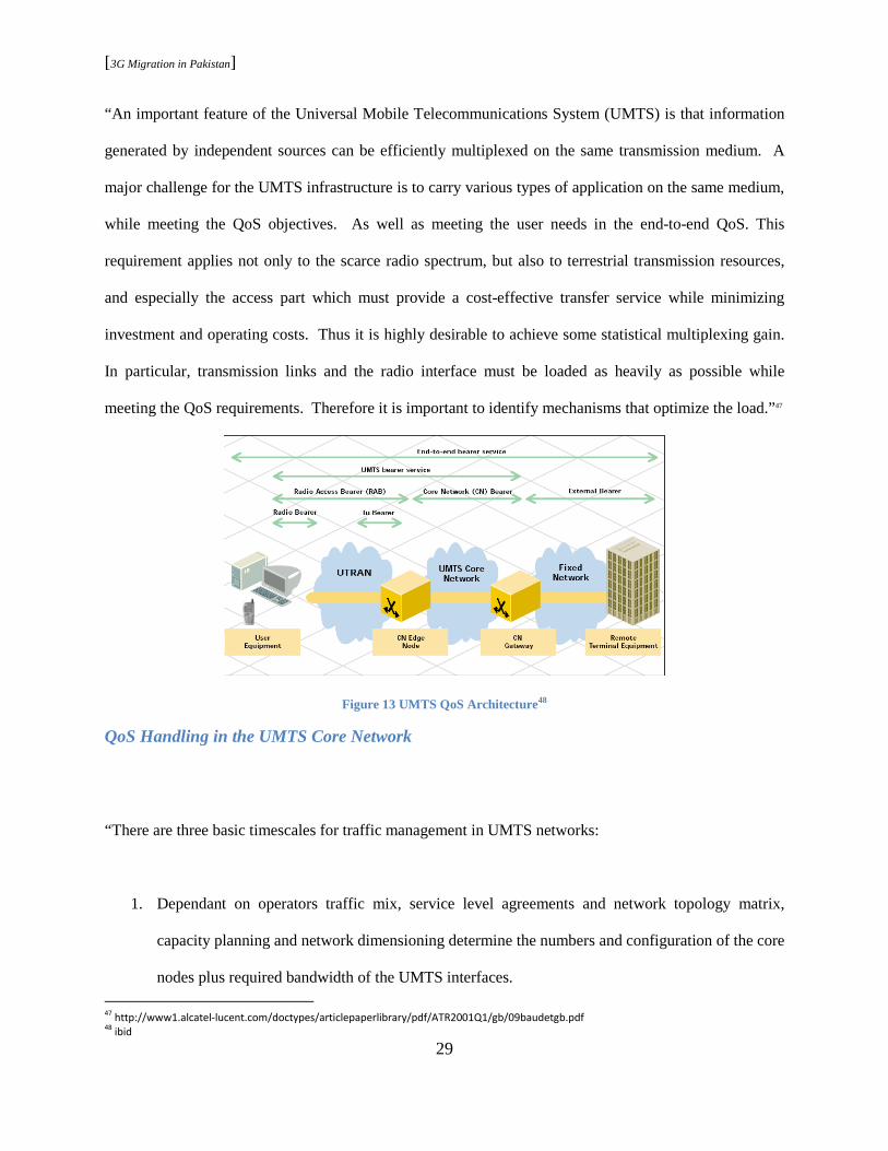
“An important feature of the Universal Mobile Telecommunications System (UMTS) is that information
generated by independent sources can be efficiently multiplexed on the same transmission medium. A
major challenge for the UMTS infrastructure is to carry various types of application on the same medium,
while meeting the QoS objectives. As well as meeting the user needs in the end-to-end QoS. This
requirement applies not only to the scarce radio spectrum, but also to terrestrial transmission resources,
and especially the access part which must provide a cost-effective transfer service while minimizing
investment and operating costs. Thus it is highly desirable to achieve some statistical multiplexing gain.
In particular, transmission links and the radio interface must be loaded as heavily as possible while
meeting the QoS requirements. Therefore it is important to identify mechanisms that optimize the load.”47
Figure 13 UMTS QoS Architecture48
QoS Handling in the UMTS Core Network
“There are three basic timescales for traffic management in UMTS networks:
1. Dependant on operators traffic mix, service level agreements and network topology matrix,
capacity planning and network dimensioning determine the numbers and configuration of the core
nodes plus required bandwidth of the UMTS interfaces.
47
http://www1.alcatel-lucent.com/doctypes/articlepaperlibrary/pdf/ATR2001Q1/gb/09baudetgb.pdf 48
ibid

[3G Migration in Pakistan]
30
2. Initiated with every call setup, CAC determines whether or not the new call can be accepted
while guaranteeing the QoS of established calls.
3. Policing, scheduling and congestion mechanisms are performed each time a packet is sent and/or
received (typically microseconds). Policing and buffer acceptance mechanisms are algorithms
that decide when a packet arrives, whether or not it can be accepted. Scheduling algorithms
decide when (and which) packet to send first.
The QoS features supported by the UMTS core network determine its ability to differentiate between
services offered to subscribers. This capability is offered end-to end to ensure necessary resources are
allocation and guaranteeing the negotiated quality of service.”49
QoS Handling in the UMTS Terrestrial Radio Access Network
Radio access bearer services, RAB, are established dynamically to support one or several
applications for a given MS. Each RAB is characterized by QoS attributes which are derived from
the characteristics of the application. The UTRAN simply obtains the RAB QoS attributes from
the core network when the RAB is established and maintains required QoS levels. The RAB is
always established at the request of the core network, which retains ownership of the RAB
throughout its life. Once the UTRAN has committed to a given QoS level, this should not be
downgraded by the UTRAN without a prior modification request from the core network. In
particular, this requirement applies to mobile terminals, which frequently experience varying
radio conditions as they move from cell to cell. Given all WCDAM users share the same
resources both in the frequency and time domains, it is essential to maintain a low level of radio
interference throughout the system. To this end, power control constrains the transmission power
to/from each user between appropriate limits: not too high, to preserve the UMTS cell traffic
49
ibid

[3G Migration in Pakistan]
31
capacity and not too low, to avoid excessive transmission errors that would lower the overall bit
rate. In addition, QoS monitoring is essential to ensure that the QoS requirements are met but not
exceeded. Smoothing of the traffic flow and congestion avoidance is essential. Radio Admission
Control (RAC), radio resource allocation and management, and radio load control functions are
key features for handling QoS within UTRAN.50
Figure 14 RAB Service Establishment Principles 51
2.6.6 Hand Over
UTRAN interface Iur exists between the RNCs and supports inter-RNC mobility and soft handover
between Node Bs connected to different RNCs. “These handovers cop with requirements of load control,
coverage provisioning and offering quality of services. As a result, handover failures are reduced
substantially.”52
Hard Handover
50
http://www1.alcatel-lucent.com/doctypes/articlepaperlibrary/pdf/ATR2001Q1/gb/09baudetgb.pdf 51
ibid 52
http://oldwww.com.dtu.dk/research/networks/OPNET/UMTS_handover.pdf
[3G Migration in Pakistan]
32
“Hard handover means that all the old radio links in the UE are removed before the new radio links are
established. Hard handover can be seamless or non-seamless. Seamless hard handover means that the
handover is not perceptible to the user. In practice a handover that requires a change of the carrier
frequency (inter-frequency handover) is always performed as hard handover.”53 The mobile station
performs a handover when the signal strength of a neighboring cell exceeds the signal strength of the
current cell with a given threshold. To decrease blocking probabilities experienced by users entering a
new cell and to avoid poor utilization of cell capacity (mobility issues in 2G networks), WCDMA offers
soft and softer handovers. “Typically hard handovers are only used for coverage and load reasons, while
soft and softer handover are the main means of supporting mobility.”54
Soft Handover
“Soft and softer handover are the CDMA revolutionary features. Soft handover means that the radio links
are added and removed in a way that the UE always keeps at least one radio link to the UTRAN. Soft
handover is performed by means of macro diversity, which refers to the condition that several radio links
are active at the same time. Normally soft handover can be used when cells operated on the same
frequency are changed.”55
Softer Handover
“Softer handover is a special case of soft handover where the radio links that are added and removed
belong to the same Node B (i.e. the site of co-located base stations from which several sector-cells are
served. In softer handover, macro diversity with maximum ratio combining can be performed in the Node
53
http://www.umtsworld.com/technology/handover.htm 54
http://oldwww.com.dtu.dk/research/networks/OPNET/UMTS_handover.pdf 55
http://www.umtsworld.com/technology/handover.htm
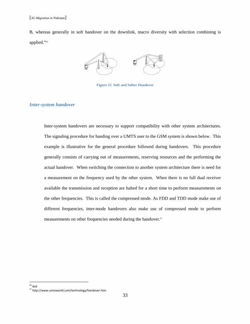
[3G Migration in Pakistan]
33
B, whereas generally in soft handover on the downlink, macro diversity with selection combining is
applied.”56
Figure 15 Soft and Softer Handover
Inter-system handover
Inter-system handovers are necessary to support compatibility with other system architectures.
The signaling procedure for handing over a UMTS user to the GSM system is shown below. This
example is illustrative for the general procedure followed during handovers. This procedure
generally consists of carrying out of measurements, reserving resources and the performing the
actual handover. When switching the connection to another system architecture there is need for
a measurement on the frequency used by the other system. When there is no full dual receiver
available the transmission and reception are halted for a short time to perform measurements on
the other frequencies. This is called the compressed mode. As FDD and TDD mode make use of
different frequencies, inter-mode handovers also make use of compressed mode to perform
measurements on other frequencies needed during the handover.57
56
ibid 57
http://www.umtsworld.com/technology/handover.htm

[3G Migration in Pakistan]
34
Figure 16 Inter System Hand Over
2.7 Evolution (IMT-SC/EDGE)
“EDGE provides an evolutionary path that enables existing 2G systems to deliver 3G services in
existing spectrum bands. It reuses the GSM carrier bandwidth and time slot structure.”58
GSM/enhanced data rates for global evolution or GSM/EDGE standard has been taking steps to
define a fully capable 3G mobile RAN. 3GPP release 5 specifies GSM/EDGE RAN (GERAN)
that can connect to 3G core and provide the same set of services as UMTS UTRAN.
58
Wireless network evolution : 2G to 3G

[3G Migration in Pakistan]
35
2.7.1 GERAN Architecture
59
Figure 17 GERAN Architecture
Figure 2.10 is an evolution of figure 2.1 with the addition of GSM/EDGE Radio Access Network
and IMS. IP multimedia subsystem, added for maximum flexibility and independence from
access technologies, falls outside the scope of this paper and hence is not discussed. Also, the
core and the UE part of this network are similar to UMTS architecture as discussed.
GERAN Interfaces
Legacy Interfaces
1. Gb Interface connects serving GPRS support node SGSN and Base Station Subsystem
(BSS)
2. A Interface connects BSC and MSC60
59
www.nmscommunications.com

[3G Migration in Pakistan]
36
New Interfaces
The general protocol model for new interfaces is based on the protocol model used in UMTS.
The logical independence of layers and planes adds additional flexibility so that transport layer
protocol may be changed if needed with no impact on the radio interface.
Figure 18 UTRAN/ GERAN Protocol Model
1. Iu interface similar and discussed in UTRAN.
2. Iur-g interface is based on UTRAN Iur interface and supports logical connection between
any two GERAN.61
“The functionality split across these interfaces is aligned with UTRAN-CN split. For GERAN
this means that the functionalities like ciphering and header adaptation are moved from the CN
and are part of the radio access net-work. In addition the cell level mobility management tasks
60
http://www.benoa.net/publications/ict2001.pdf 61
ibid

[3G Migration in Pakistan]
37
are solely part of the operator deploying both radio access technologies (GERAN and UTRAN)
may operate one single core network, and both access technologies can provide the same set of
services. This includes provision of all the UMTS traffic classes also through GERAN. For the
network and terminal manufacturers, the harmonization gives benefit in form of synergies in
protocol and interface implementation. The harmonization of the GERAN and UTRAN architec-
tures simplifies the future development of these radio access technologies, e.g., towards an All-IP
system. The IP transport is expected to give benefit for the operators by bringing down the
transmission costs.”62
2.7.2 GERAN Radio Protocols
1. Packet Data Convergence Protocol – PDCP is for the transfer of user data using services
provided by the RLC and header adaptation of the redundant network PDU control information
(IP headers) in order to make the transport over the RF spectrum efficient.
2. Radio Resource Control - RRC is based on both GSM RR and UTRAN RRC specifications.
Functions include broadcast of information related to the non-access stratum (core network) and
the access stratum, paging/notification, routing of higher layer PDUs, control of requested QoS
and security functions, and MS measurement reporting and control of the reporting.
3. Link Control RLC allows for the data transfer in various modes and in addition notifies
unrecoverable errors to upper layer. When in transparent mode, RLC has no functionality and
does not alter the data units of the upper layer. In non-transparent mode, the RLC is responsible
for ciphering RLC PDUs in order to prevent any unauthorized acquisition of data. In
acknowledged mode, Backward Error Correction (BEC) procedures are provided that allow error-
free transmission of RLC PDUs.
62
ibid

[3G Migration in Pakistan]
38
4. Medium Access Control – MAC allows the transmission over the physical layer of upper layer
PDUs in dedicated or shared mode. A MAC mode is associated with a physical sub channel for
use by one or more mobile stations (dedicated or shared mode respectively) and handles the
access to and multiplexing onto the physical sub channels of mobile stations and traffic flows.63
2.7.3 Quality of Service
“RRC realizes the QoS requirements of the RAB by establishing a RB between MS and GERAN. For
each RB, RRC allocates either a dedicated or a shared channel. In case of dedicated channels, RRC also
takes care of radio resources allocations. In case of shared channels, MAC takes care of radio resource
allocations.”64 As explained in UTRAN, “QoS is divided into control plane (CAC and QoS preserving)
and user plane (link adaptation, traffic conditioning, packet scheduler, and power control).”65
2.7.4 Services and Traffic types
“As part of RAN harmonization, same services and traffic types apply to GERAN.” 66
2.7.5 Hand Over
Being a GSM evolution, the handover allowed is hard handover. Details are provided in UTRAN
handover discussion.
63
ibid 64
http://www.benoa.net/publications/ict2001.pdf 65
http://74.125.95.132/search?q=cache:s3_NvXfdpMIJ:www.it.lut.fi/kurssit/03-04/010990000/gsm- 66
Advances in 3G enhanced technologies for wireless communications

[3G Migration in Pakistan]
39
2.7.6 Air Interface
Air access medium technique used is TDMA running FDMA (details provided in chapter one). “The
carrier bandwidth is 200 kHz, with 8 timeslots per carrier, each containing 148 bits. The GSM Gaussian
Minimum Shift Keying (GMSK) modulation scheme is supported in addition to a new 8-PSK modulation
scheme.”67 “The basic goal with is to enhance the data throughput capabilities of a GSM/GPRS network
or squeeze more bits per second out of the same 200-kHz carrier and eight-timeslot TDMA. The result is
that EDGE can theoretically support speeds of up to 384 Kbps. Thus, it is clearly more advanced than
GPRS, but still does not meet the requirements for a true 3G system (which should support speeds of up
to 2 Mbps).” 68
Air Interface Coding Schemes and Data Rates
“If a BTS supports both GMSK and 8-PSK modulation and has the same output power for both, then the
cell footprint is smaller for 8-PSK than for GMSK. Recognizing this limitation, however, RF condition
may change the scheme use. As a user moves towards the edge of a cell, the effect of lower signal to
noise will mean that the network can reduce the user's throughput, either by changing the modulation
scheme to GMSK or by changing the coding scheme to include greater error detection. All that the user
will notice is somewhat slower throughput.” 69
67
EDGE AIR-INTERFACE CAPACITY ANALYSIS 68
3G wireless network 69
3G wireless network

[3G Migration in Pakistan]
40
Figure 19 Modulation and Data Rates70
2.7.7 GERAN Evolution
Current EDGE peak data rates of 300 kbps cannot cope with the data rates of 7.2 Mbps provided
by WCDMA/HSPA networks. Still, the enormous GSM/EDGE subscriber base motivates mobile
operators to continue investing in network upgrades to provide higher data rates at minimum cost.
EDGE Evolution, also standardized by 3GPP, consists of a subset of features which allow
quadrupling the downlink data rates compared to legacy EDGE performance. Introduction of
new modulation schemes, e.g., 32 QAM and higher symbol rate will boost data rates up to 118.4
kbps per timeslot. In combination with dual downlink carrier, mobile terminals will be able to
allocate ten downlink timeslots which will enable peak data rates of 1.2 Mbps. Additional
improvement of EDGE Evolution end user performance will be provided by reduced latency,
turbo codes and mobile receive diversity techniques. All these features together will provide
comparable performances with 3G technology and more importantly, enable true service
transparency between 2G and 3G networks. Implementing EDGE Evolution improvements will
70
3G wireless network

[3G Migration in Pakistan]
41
mostly impact mobile terminal side. Most of the proposed enhancements can be implemented in
EDGE networks only with software upgrades, without requiring any hardware modification.71
3GPP did major work in Release 7 in order to make GERAN networks act both as a competitor and a
complement to the HSPA evolution and LTE (chapter 5). Focusing on the data rates, there are two major
features: Downlink Dual Carrier (DLDC), which is only defined for DL, and EGPRS-2, which can exist
for both UL and DL.
EGPRS-2
“HOM, turbo codes and HSR enhancements are bundled together by the name of EGPRS-2 Uplink and
Downlink. HOM and turbo codes are already supported by latest base stations and can be implemented
only with a software upgrade. Introduction of HSR will most probably require a new pulse shaping filter
so transceiver boards on base stations will have to be replaced.”72
1. Turbo code TC: Already used in 3G WCDMA networks, TC outperforms legacy convolutional
codes in term of error correction, improving channel robustness, and further diminishing the
drawback of higher BER for HOM.
2. Higher order modulation (HOM): Introduction of HOM schemes, such 16QAM and 32QAM,
enabled via MSRD gains, will increase the bit per symbol rate to 4 and 5 respectively. HOM
takes advantage of margin in the radio link, which may exist in many locations within a cell.
71
Capabilities and Impacts of EDGE Evolution toward Seamless Wireless Networks 72
Capabilities and Impacts of EDGE Evolution toward Seamless Wireless Networks; To maximize the fraction of legacy hardware where these
features can be implemented, different ambition levels are specified: EGPRS-2A downlink: 8-PSK+16/32QAM+Turbo Codes EGPRS-2A uplink:
16QAM EGPRS-2B downlink: QPSK+16/32QAM+TC+ HSR EGPRS-2B uplink: 16/32QAM+HSR
[3G Migration in Pakistan]
42
3. Dual Symbol Rate: DSR enables the use of wider band carrier for higher average and peak bit
rates. The need for higher bit rates makes favorable the use of faster symbol rate. Currently, the
legacy GSM/EDGE symbol duration is 3.69 µs while EDGE evolution standardizes 3.077 µs
symbol duration. This reduction of symbol duration allows a 20% increase of the symbol rate,
resulting in an equivalent data throughput increase.73
Downlink Dual Carrier
DLDC allows one end user to be assigned the use of timeslots from two carriers, increasing
average and peak bit rates. Downlink dual carrier helps to overcome a fundamental limitation of
GSM, which is the 200 kHz channel bandwidth. Benefits of second carriers includes: rapid
processing of data in MS leading to more responsive applications and an improved subscriber
experience, increase flexibility in bandwidth allocation, more efficient use of radio resource
increases system efficiency. Also, with two carriers, only half the slots need to be found on a
single carrier frequency to get the same throughput. The probability of successfully using
“stranded” timeslots increases which improves network efficiency. Introducing the capability to
send data on two carriers simultaneously will double the data rate in a very straightforward and
backward-compatible way.74
MSRD via Dual Antenna Interference Cancellation (DAIC)
73
Capabilities and Impacts of EDGE Evolution toward Seamless Wireless Networks 74
Capabilities and Impacts of EDGE Evolution toward Seamless Wireless Networks
[3G Migration in Pakistan]
43
Receive diversity capability in the mobile station increases sensitivity and robustness in areas of
high interference and dense deployment implying significant downlink network capacity
improvement if the mobile penetration rate is high. In case of low penetration, MS that support
MSRD will see higher average throughput across the entire SNR range. This gives an increase in
the average downlink throughput of around 30% compared to conventional receivers and pertains
to greater coverage by MS. Hence, BTS can use power control to reduce the output power to an
MSRD capable mobile station, reducing interference across the cell which increasing capacity.75
MSRD provides better sensitivity since it mitigates effects of fast fading. Users situated in areas
with poor EDGE coverage will be able to achieve satisfactory data rates.76
Functionality to reduce latency times
End-to-end system latency is one of the most sensitive parameters that affect data throughput.
The 3GPP requirement is to achieve latency below 100ms (135 ms was reduced to 80 ms) on the
radio interface. Two enhancements are combined to achieve an overall improvement in latency:
reduction of the transmission time interval (TTI) and increased efficiency of acknowledging
received data. Reducing the TTI gives benefits across all radio conditions, whereas improving
the efficiency in acknowledged mode of operation provides the highest benefit in poor channel
conditions where the number of retransmissions can be large. Reducing the overall latency has an
important second order effect on mean/average and peak bit rates as well, since as the bit rate on
the link becomes higher the maximum buffer window size can limit the transmission rate.
75
3G Americas, The case for evolved EDGE, august 2008 76
Capabilities and Impacts of EDGE Evolution toward Seamless Wireless Networks
[3G Migration in Pakistan]
44
Therefore there is limited advantage to increasing the data throughput without also decreasing the
latency, as the latency becomes a limiting and increasingly significant limiting factor.77
Data Rates
“Predictions show that by combining EGPRS2-A downlink enhancements, MSRD and dual
carrier on downlink with 5 timeslots each for a total of 10 timeslots, data rates up to 1 Mbps on
downlink can be achieved in the serving cell vicinity. This performance represents the fundament
to guarantee seamless network operations between GSM/EDGE and WCDMA/HSPA networks.
Based on EGPRS2-A enhancements, this prediction doesn’t require any hardware modification in
the base station. Eventual hardware constraints from terminal side can be easily surmounted due
to simplicity of implementation, lower cost and shorter terminal lifetime. Considering that by
using 32QAM together with HSR, data rate per timeslot can be elevated up to 118.4 kbps and for
state-of-the-art handsets supporting 5 timeslots together with dual downlink carrier the theoretical
peak throughput can be further boosted to the maximum value of 1.184 Mbps on downlink. Multi
RAT terminals will be able to more readily incorporate features of evolved EDGE with less
impact on cost and size as they leverage reuse of 3G elements, thus making them ideal fabric for
a feasible implementation of EDGE Evolution features.78
77
3G Americas, The case for evolved EDGE, august 2008 78
Capabilities and Impacts of EDGE Evolution toward Seamless Wireless Networks

[3G Migration in Pakistan]
45
Figure 20 Predicted user throughput 79
79
ibid

[3G Migration in Pakistan]
46
Chapter 3 - Beyond 3G
The high data rate packet world of 3G has come a long way since its initial release and deployment. At
this point in time, W-CDMA, or Evolved EDGE, is not the only candidate for providing 3G services in
Pakistan. The succeeding concepts introduced by 3GPP in the recent years ( HSPA, HSPA+, LTE), also
referred to as 3.5 G or 3.75 G , can become equally significant candidates.
3.1 High Speed Packet Access (HSPA)
“HSPA is a 3.5G technology which provides theoretical download speeds of up to 7.2Mbps with an
upgrade path to 80 Mbps and enables data transmission speeds of up to 14.4Mbit/s per user.”80
“The challenge facing the mobile telecommunications industry today is how to continually improve the
end-user experience, offer appealing services through a delivery mechanism which offers improved
speed, service attractiveness and service interaction. HSPA is a generic term to refer to improvements in
the UMTS Radio Interface, downlink (HSDPA) and uplink (HSUPA. Both can be implemented and co
exists in the standard 5 MHz carrier of UMTS networks. There is no change required of the core network
outside of the capacity increases that will be required to handle the expected increase in traffic
generated.”81
High Speed Downlink Packet Access (HSDPA)
HSDPA introduces a number of new technical capabilities to the radio access network, which when
combined offer a significant improvement for both end users and operators. These capabilities are:
80
http://www.webbuyersguide.com/resource/white-paper/9246/UMTS-Evolution-from-3GPP-Release-7-to-Release-8-HSPA-and-SAE-LTE 81
www.umts-forum.org/component/option,com.../task.../Itemid,12/

[3G Migration in Pakistan]
47
1. A new common High Speed Downlink Shared Channel (HS-DSCH) which can be simultaneously
shared by multiple users,
2. The use of a shorter Transmission Time Interval (TTI) of 2ms, which enables higher speed
transmission in the physical layer,
3. The use of fast scheduling which enables accommodation of variations arising from changing
radio condition,
4. The use of Adaptive Modulation and Coding (AMC), leading to a higher data rate for users with
favorable radio conditions,
5. The use of fast retransmission based on fast Hybrid Automatic Response request (HARQ)
techniques enables erroneous packets to be resent within a 10ms window, ensuring that the TCP
throughput remains high.82
High Speed Uplink Packet Access (HSUPA)
“Enhanced Dedicated Channel (E-DCH), name adopted in 3GPP for HSUPA, is next step to HSDPA and
the two are complimentary to one another. It seems that HSDPA is the more advanced of the two
technologies, but when function side-by-side the resulting system will benefit with major data transfer
speed enhancements for receiving or sending.”83 “Key technical capabilities introduced with HSUPA are;
a new dedicated uplink channel, introduction of H-ARQ and fast Node B scheduling.”84 “Via E-DCH,
HSUPA employs link adaptation methods similar to those employed by HSDPA including: Higher-order
modulation in addition to the existing QPSK and 16-QAM. Similarly to HSDPA, there will be a packet
scheduler, but it will operate on a request-grant principle where the UE (User Equipment) requests
permission to send packets and the scheduler decides when and how many UEs will be allowed to do so.
Unlike in HSDPA, soft and softer handovers will be allowed for packet transmissions. Both, HSDPA and 82
www.umts-forum.org/component/option,com.../task.../Itemid,12/ 83
http://www.mobilecomms-technology.com/projects/hsupa/ 84
www.umts-forum.org/component/option,com.../task.../Itemid,12/

[3G Migration in Pakistan]
48
HSUPA, require no new infrastructure. The network equipment need only be updated with new
software.”85 In a nutshell,
Figure 21 HSPA Data Rates 86
3.2 HSPA+
“Objective is to enhance performance of HSPA based radio networks in terms of spectrum efficiency,
peak data rate and latency, and exploit the full potential of WCDMA based 5 MHz operation. Important
features of HSPA+ are downlink MIMO (Multiple Input Multiple Output), higher order modulation for
uplink and downlink, improvements of layer 2 protocols, and continuous packet connectivity”87. MIMO
technology is discussed in detail in LTE section.
With MIMO technologies and higher order modulation, HSPA+ will eventually be capable of
delivering 42 Mbit/s peak bit rate in the downlink and 11 Mbit/s in the uplink over a 5 MHz
channel. HSPA+ introduces an optional all-IP flat architecture that reduces latency to around 10
ms and provides backhaul based on IP/MPLS transport. Base stations in IP flat architecture,
evolves to an IP router that connects to the network via standard gigabit Ethernet connected to the
Internet. By eliminating the need for RNC, the load on SGSN reduces, resulting in a significant
reduction of the cost per bit. HSPA+ continues to evolve, and future combinations of multicarrier
85
http://www.mobilecomms-technology.com/projects/hsupa/ 86
www.umts-forum.org/component/option,com.../task.../Itemid,12/ 87
UMTS_Long_Term_Evolution__LTE__Technology_Introduction
[3G Migration in Pakistan]
49
techniques and MIMO technologies could in principle achieve 84 Mbit/s peak on the downlink
and 23 Mbit/s peak uplink. These rates could only be achieved by operators with access to
multiple adjacent paired 5 MHz bands. They are the highest data rates that could be achieved in
existing 3G networks based on 5 MHz WCDMA technology. Further improvements can only
come with a new mobile network technology. HSPA+ is a logical development of the
3G/WCDMA approach, leveraging operator investments in HSPA and enabling a lower cost per
bit. It is also the stepping stone to an entirely new radio platform called 3GPP Long Term
Evolution (LTE).88
3.3 Long Term Evolution (LTE)
In the current (HSxPA) specifications, systems are capable of supporting high-speed packet access for
both downlink (up to 14 Mbps) and uplink (up to 5.76 Mbps). Although HSxPA systems offer substantial
improvement for packet data transmission over earlier UMTS systems, their designs were limited by
compatibility requirements with previous generations of UMTS specifications. With the emergence of
packet-based mobile broadband systems such as WiMAX 802.16e, it is evident that a comprehensive
long- term evolution (LTE) of UMTS is required to remain competitive in the long term.89
While work continues on the evolution of HSPA, one of the main areas of focus for 3GPP Rel-8 is the
introduction of the EPS. “Evolved Packet System comprises E-UTRAN (Evolved UTRAN) on the access
side and EPC (Evolved Packet Core) on the core side. EPC is also known as SAE (System Architecture
Evolution) and EUTRAN is also known as LTE.”90
88
UMTS_Forum_MBB_LTE_White_Paper_February_2009_v2 89
LTEAirInterfaceWhitePaper 90
Long_Term_Evolution

[3G Migration in Pakistan]
50
3.3.1 Evolved Packet System (EPS) Architecture
In its most basic form, the EPS architecture consists of only two nodes in the user plane: a base station
and a core network Gateway (GW). The node that performs control-plane functionality (MME) is
separated from the node that performs bearer-plane functionality (GW), with a well-defined open
interface between them (S11), and by using the optional interface S5, the Gateway (GW) can be split into
two separate nodes (Serving Gateway and the PDN Gateway). This allows for independent scaling and
growth of throughput traffic and control signal processing, and operators can also choose optimized
topological locations of nodes within the network in order to optimize the network in different aspects.91
The basic architecture of the EPS contains the following network elements:
Figure 22 Detailed EPS architecture view
91
3GPPRel-7andRel-8_White_Paper07-08-08
[3G Migration in Pakistan]
51
1. Mobility Management Entity (MME): MME manages mobility, UE identities and security
parameters. MME functions include: NAS signaling and related security, inter CN node signaling
for mobility between 3GPP access networks (terminating S3), Idle mode UE Tracking and Reach
ability (including control and execution of paging retransmission), Roaming (terminating S6a
towards home HSS), GW selections (Serving GW and PDN GW selection), MME selection for
handovers with MME change, SGSN selection for handovers to 2G or 3G 3GPP access networks,
HRPD access node (terminating S101 reference point) selection for handovers to HRPD,
Authentication, Bearer management functions including dedicated bearer establishment.
2. Serving Gateway: The Serving Gateway is the node that terminates the interface towards
EUTRAN. For each UE associated with the EPS, at a given point of time, there is one single
Serving Gateway. Serving GW functions include: the local Mobility Anchor point for inter-
eNodeB handover, mobility anchoring for inter-3GPP mobility (terminating S4 and relaying the
traffic between 2G/3G system and PDN Gateway), EUTRAN idle mode downlink packet
buffering and initiation of network triggered service request procedure, transport level packet
marking in the uplink and the downlink, e.g., setting the DiffServ Code Point, based on the QCI
of the associated EPS bearer, depending on the user and QCI granularity for inter-operator
charging, lawful Interception, packet routing and forwarding.
3. PDN Gateway: The PDN Gateway is the node that terminates the SGi interface towards the
PDN. If a UE is accessing multiple PDNs, there may be more than one PDN GW for that UE.
PDN GW functions include: mobility anchor for mobility between 3GPP access systems and non-
3GPP access systems, policy enforcement, Per-user based packet filtering (by e.g., deep packet
inspection), Charging support, Transport level packet marking in the uplink and downlink, e.g.,
setting the DiffServ Code Point, based on the QCI of the associated EPS bearer, lawful
Interception, UE IP address allocation, packet screening.

[3G Migration in Pakistan]
52
4. Evolved UTRAN (eNodeB): The eNodeB supports the LTE air interface and includes functions
for radio resource control, user plane ciphering and Packet Data Convergence Protocol (PDCP)92.
Interfaces and Protocols
To support the new LTE air interface as well as roaming and mobility between LTE and
UTRAN/GERAN, the EPS architecture contains the following interfaces:
1. S1-MME: Reference point for the control plane protocol between E-UTRAN and MME.
2. S1-U: Serves as a reference point between E-UTRAN and Serving GW for the per bearer user
plane tunneling and inter eNodeB path switching during handover.
3. S3: Enables user and bearer information exchange for inter 3GPP access network mobility. It is
based on Gn reference point as defined between SGSNs.
4. S4: Provides related control and mobility support between GPRS Core and the 3GPP Anchor
function of Serving GW and is based on Gn reference point as defined between SGSN and
GGSN.
5. S5: Provides user plane tunneling and tunnel management between Serving GW and PDN GW. It
is used for Serving GW relocation due to UE mobility and if the Serving GW needs to connect to
a non-collocated PDN GW for the required PDN connectivity.
6. S6a: Enables transfer of subscription and authentication data for authenticating/ authorize user
access to the evolved system (AAA interface) between MME and HSS.
7. Gx: Provides transfer of (QoS) policy and charging rules from PCRF to Policy and Charging
Enforcement Function (PCEF) in the PDN GW.
92
3GPPRel-7andRel-8_White_Paper07-08-08
[3G Migration in Pakistan]
53
8. S8: Inter-PLMN reference point providing user and control plane between the Serving GW in the
VPLMN and the PDN GW in the HPLMN. It is based on Gp reference point as defined between
SGSN and GGSN. S8 is the inter PLMN variant of S5.
9. S9: Provides transfer of (QoS) policy and charging control information between the Home PCRF
and the Visited PCRF in order to support local breakout function.
10. S10: Serves as a reference point between MMEs for MME relocation and MME to MME
information transfer.
11. S11: Serves as a reference point between MME and Serving GW.
12. S12: Serves as a reference point between UTRAN and Serving GW. It is based on the Iu-u/Gn-u
reference point using the GTP-U protocol as defined between SGSN and UTRAN and its usage is
an operator configuration option.
13. S13: Enables UE identity check procedure between MME and EIR.
14. SGi: Reference point between the PDN GW and the packet data network. Packet data network
may be an operator external public or private packet data network or an intra operator packet data
network, e.g., for provision of IMS services. This reference point corresponds to Gi for 3GPP
accesses.
15. Rx: The Rx reference point resides between the AF and the PCRF in the TS 23.203.93
3.3.2 Evolved UTRAN
3GPP is developing the evolution of mobile communications systems beyond GSM/EDGE and
WCDMA-HSPA systems. “3G Mobile System Long Term Evolution (LTE)” targets capacity and data
93
3GPPRel-7andRel-8_White_Paper07-08-08
[3G Migration in Pakistan]
54
rate speed and throughput enhancements and reduced latency to support new services and features
requiring higher levels of capability and performance. Key feature include:
1. Reduced cost per bit
2. Increased service provisioning – more services at lower cost with better user experience
3. Flexibility of use of existing/new frequency bands
4. Simplified architecture, open interfaces
5. Allows for reasonable terminal power consumption
6. LTE utilizes a new radio air interface technology known as Orthogonal Frequency Division
Multiple Access (OFDMA) to provide several key benefits, including significantly increased peak
data rates, increased cell edge performance, reduced latency, scalable bandwidth, co-existence
with GSM/EDGE/UMTS systems, and reduced CAPEX/OPEX.94
“LTE is backward compatible with non-3GPP as well as 3GPP technologies. Its ability to interwork with
legacy and new networks, and its seamless integration of Internet applications will drive the convergence
between fixed and mobile systems and facilitate new types of services. LTE heralds a new era with the
transition from circuit switched approaches for voice traffic to a fully packet switched model. This
transition from existing networks that combine circuit and packet switching to all-IP requires considerable
simplification of the system architecture.”95
“In November 2007, one of the industry’s first multi-vendor over-the-air LTE interoperability testing
initiatives was conducted successfully. The first field trials for LTE are planned for 2008, with
94
lte_3gpp 95
UMTS_Forum_MBB_LTE_White_Paper_February_2009_v2

[3G Migration in Pakistan]
55
commercial availability in 2009/2010 timeframe.”96 “LTE provides downlink peak rates of at least
100Mbit/s, 50 Mbit/s in the uplink and RAN round-trip times of less than 10ms. LTE supports flexible
carrier bandwidths, from 1.4MHz up to 20MHz as well as both FDD and TDD. The goals for LTE
include improving spectral efficiency, lowering costs, improving services, making use of new spectrum
and refarmed spectrum opportunities and better integration with other open standards.”97
“The evolved UTRAN consists of interconnected E-Node Bs providing the evolved UTRA U-plane and
C-plane protocol terminations towards the UE. The E-Node B hosts the functions for Radio Resource
Management, including Radio Bearer Control, Radio Admission Control, Connection Mobility Control,
and Dynamic Resource Allocation.”98
Access Scheme
“The technology solution chosen by 3GPP for the LTE air interface uses Orthogonal Frequency Division
Multiplexing (OFDM) and MIMO technologies, together with high rate modulation. LTE uses the same
principles as HSPA for scheduling of shared channel data and fast link adaptation, enabling the network
to optimize cell performance dynamically. In fact LTE is based entirely on shared and broadcast channels
and contains no dedicated channels carrying data to specific users. This increases the efficiency of the air
interface as the network no longer has to assign fixed levels of resource to each user but can allocate air
interface resources according to real-time demand.”99
LTE Downlink Transmission Scheme OFDMA
96
3GPPRel-7andRel-8_White_Paper07-08-08 97
Long_Term_Evolution 98
lte_3gpp 99 UMTS_Forum_MBB_LTE_White_Paper_February_2009_v2
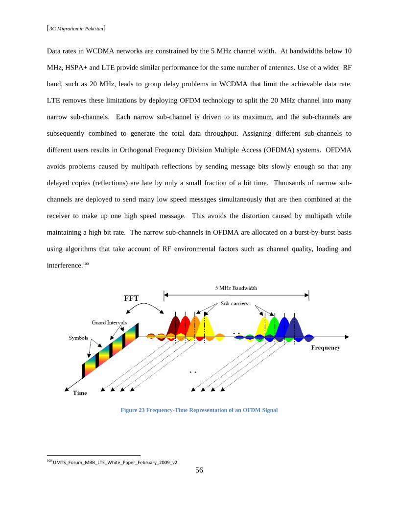
[3G Migration in Pakistan]
56
Data rates in WCDMA networks are constrained by the 5 MHz channel width. At bandwidths below 10
MHz, HSPA+ and LTE provide similar performance for the same number of antennas. Use of a wider RF
band, such as 20 MHz, leads to group delay problems in WCDMA that limit the achievable data rate.
LTE removes these limitations by deploying OFDM technology to split the 20 MHz channel into many
narrow sub-channels. Each narrow sub-channel is driven to its maximum, and the sub-channels are
subsequently combined to generate the total data throughput. Assigning different sub-channels to
different users results in Orthogonal Frequency Division Multiple Access (OFDMA) systems. OFDMA
avoids problems caused by multipath reflections by sending message bits slowly enough so that any
delayed copies (reflections) are late by only a small fraction of a bit time. Thousands of narrow sub-
channels are deployed to send many low speed messages simultaneously that are then combined at the
receiver to make up one high speed message. This avoids the distortion caused by multipath while
maintaining a high bit rate. The narrow sub-channels in OFDMA are allocated on a burst-by-burst basis
using algorithms that take account of RF environmental factors such as channel quality, loading and
interference.100
Figure 23 Frequency-Time Representation of an OFDM Signal
100
UMTS_Forum_MBB_LTE_White_Paper_February_2009_v2
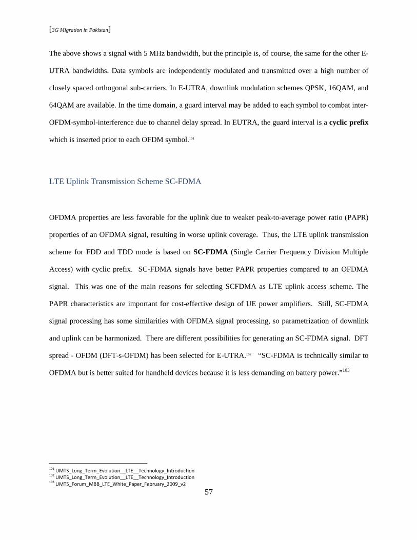
[3G Migration in Pakistan]
57
The above shows a signal with 5 MHz bandwidth, but the principle is, of course, the same for the other E-
UTRA bandwidths. Data symbols are independently modulated and transmitted over a high number of
closely spaced orthogonal sub-carriers. In E-UTRA, downlink modulation schemes QPSK, 16QAM, and
64QAM are available. In the time domain, a guard interval may be added to each symbol to combat inter-
OFDM-symbol-interference due to channel delay spread. In EUTRA, the guard interval is a cyclic prefix
which is inserted prior to each OFDM symbol.101
LTE Uplink Transmission Scheme SC-FDMA
OFDMA properties are less favorable for the uplink due to weaker peak-to-average power ratio (PAPR)
properties of an OFDMA signal, resulting in worse uplink coverage. Thus, the LTE uplink transmission
scheme for FDD and TDD mode is based on SC-FDMA (Single Carrier Frequency Division Multiple
Access) with cyclic prefix. SC-FDMA signals have better PAPR properties compared to an OFDMA
signal. This was one of the main reasons for selecting SCFDMA as LTE uplink access scheme. The
PAPR characteristics are important for cost-effective design of UE power amplifiers. Still, SC-FDMA
signal processing has some similarities with OFDMA signal processing, so parametrization of downlink
and uplink can be harmonized. There are different possibilities for generating an SC-FDMA signal. DFT
spread - OFDM (DFT-s-OFDM) has been selected for E-UTRA.102 “SC-FDMA is technically similar to
OFDMA but is better suited for handheld devices because it is less demanding on battery power.”103
101
UMTS_Long_Term_Evolution__LTE__Technology_Introduction 102
UMTS_Long_Term_Evolution__LTE__Technology_Introduction 103
UMTS_Forum_MBB_LTE_White_Paper_February_2009_v2
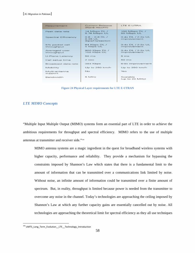
[3G Migration in Pakistan]
58
Figure 24 Physical Layer requirements for LTE E-UTRAN
LTE MIMO Concepts
“Multiple Input Multiple Output (MIMO) systems form an essential part of LTE in order to achieve the
ambitious requirements for throughput and spectral efficiency. MIMO refers to the use of multiple
antennas at transmitter and receiver side.”104
MIMO antenna systems are a magic ingredient in the quest for broadband wireless systems with
higher capacity, performance and reliability. They provide a mechanism for bypassing the
constraints imposed by Shannon’s Law which states that there is a fundamental limit to the
amount of information that can be transmitted over a communications link limited by noise.
Without noise, an infinite amount of information could be transmitted over a finite amount of
spectrum. But, in reality, throughput is limited because power is needed from the transmitter to
overcome any noise in the channel. Today’s technologies are approaching the ceiling imposed by
Shannon’s Law at which any further capacity gains are essentially cancelled out by noise. All
technologies are approaching the theoretical limit for spectral efficiency as they all use techniques
104
UMTS_Long_Term_Evolution__LTE__Technology_Introduction
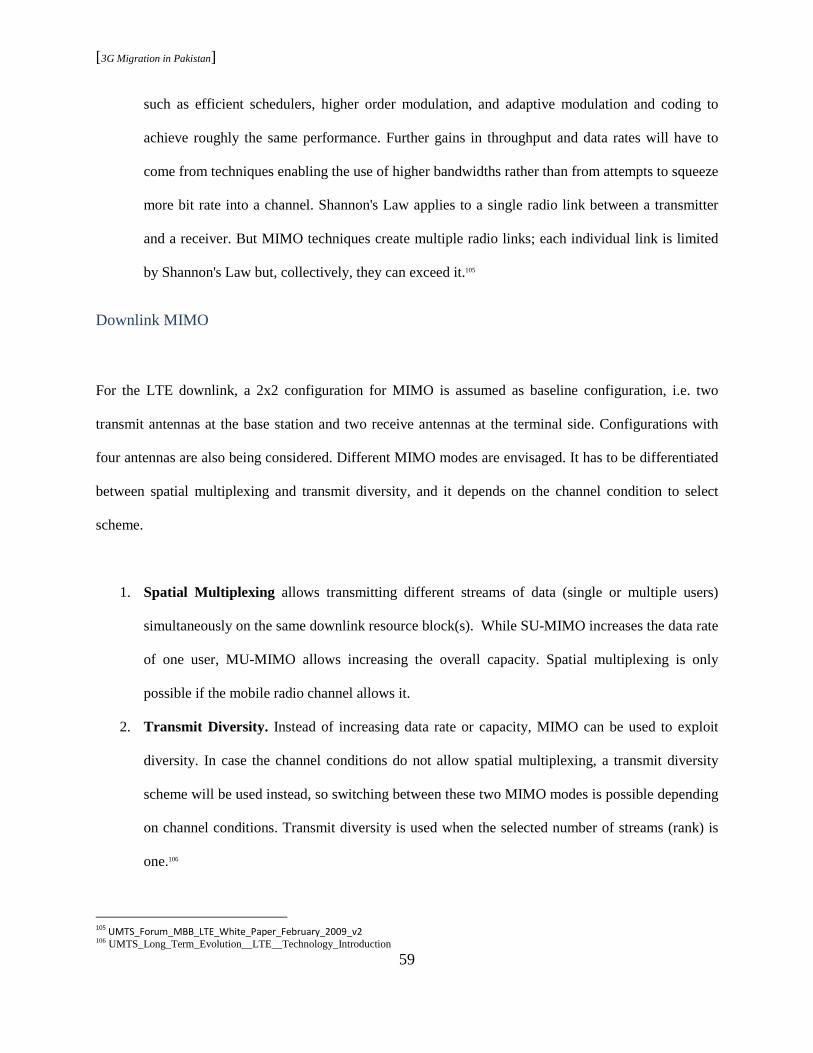
[3G Migration in Pakistan]
59
such as efficient schedulers, higher order modulation, and adaptive modulation and coding to
achieve roughly the same performance. Further gains in throughput and data rates will have to
come from techniques enabling the use of higher bandwidths rather than from attempts to squeeze
more bit rate into a channel. Shannon's Law applies to a single radio link between a transmitter
and a receiver. But MIMO techniques create multiple radio links; each individual link is limited
by Shannon's Law but, collectively, they can exceed it.105
Downlink MIMO
For the LTE downlink, a 2x2 configuration for MIMO is assumed as baseline configuration, i.e. two
transmit antennas at the base station and two receive antennas at the terminal side. Configurations with
four antennas are also being considered. Different MIMO modes are envisaged. It has to be differentiated
between spatial multiplexing and transmit diversity, and it depends on the channel condition to select
scheme.
1. Spatial Multiplexing allows transmitting different streams of data (single or multiple users)
simultaneously on the same downlink resource block(s). While SU-MIMO increases the data rate
of one user, MU-MIMO allows increasing the overall capacity. Spatial multiplexing is only
possible if the mobile radio channel allows it.
2. Transmit Diversity. Instead of increasing data rate or capacity, MIMO can be used to exploit
diversity. In case the channel conditions do not allow spatial multiplexing, a transmit diversity
scheme will be used instead, so switching between these two MIMO modes is possible depending
on channel conditions. Transmit diversity is used when the selected number of streams (rank) is
one.106
105
UMTS_Forum_MBB_LTE_White_Paper_February_2009_v2 106 UMTS_Long_Term_Evolution__LTE__Technology_Introduction

[3G Migration in Pakistan]
60
Uplink MIMO
Uplink MIMO schemes for LTE will differ from downlink MIMO schemes to take into account terminal
complexity issues. For the uplink, MU-MIMO can be used. Multiple user terminals may transmit
simultaneously on the same resource block. This is also referred to as spatial domain multiple access
(SDMA). The scheme requires only one transmit antenna at UE side, which is a big advantage. The UEs
sharing the same resource block have to apply mutually orthogonal pilot patterns. To exploit the benefit
of two or more transmit antennas but still keep the UE cost low, antenna subset selection can be used. In
the beginning, this technique will be used, e.g., a UE will have two transmit antennas but only one
transmits chain and amplifier. A switch will then choose the antenna that provides the best channel to the
eNodeB.107
Spectrum flexibility
“The focus is now on creating more usable frequencies instead of attempts to increase spectral efficiency.
Receive diversity technologies such as MIMO can do this by sending the same information from two or
more separate transmitters to an equal number of receivers, cutting down on the information loss of a
single transmission. Beam forming technologies are another approach, reducing interference by steering
radio links towards a specific user. OFDMA is a third approach that relies on increasing flexibility in the
use of spectrum. By splitting a channel into thousands of very narrow sub-channels, each on a different
frequency, each carrying a part of the signal, OFDMA provides an ensuring better support for global
roaming and delivering future economies of scale.”108
107 UMTS_Long_Term_Evolution__LTE__Technology_Introduction 108 UMTS_Forum_MBB_LTE_White_Paper_February_2009_v2

[3G Migration in Pakistan]
61
The role of IMS
A major motivation for LTE/EPC is to support Next Generation Network (NGN) philosophies
and Fixed Mobile Convergence (FMC) business models. Moving mobile networks to all-IP
enables effective convergence scenarios involving mixed technology deployments. Combined
with the IP Multimedia Subsystem (IMS), this greatly simplifies management and maintenance
requirements. Changing access technologies today – from WLAN access to an HSPA data card
for example – can require full connection, registration and authentication on each access network
followed by manual intervention to switch from one to the other. Even when the mobile device
supports both access technologies, the data flow cannot be handed over seamlessly without the
user being aware of the change. The solution is to connect 3GPP and non-3GPP mobile networks
to the core network through IMS. IMS allows seamless handover between multiple access
technologies and provides the necessary mobility and routing management. The core network
sees the mobile network as another IP network and does not need to manage mobility,
authentication or security control as the user changes access technology. IMS uses the Session
Initiation Protocol (SIP) to allow fast connection between mobile devices and the core network.
Initial setup of data sessions in traditional wireless networks can take between one and 15
seconds compared with milliseconds in a fixed network. The marriage of LTE with IMS will
provide operators with a cost effective network that allows integration with the core network for
customer care, billing and network management. It will provide mobile users with an always
connected high speed experience – truly unfettering the desktop.109
109
UMTS_Forum_MBB_LTE_White_Paper_February_2009_v2
[3G Migration in Pakistan]
62
3.4 4G
“There is confusion within the wireless industry, as to what exactly constitutes 3G, because of the
increasing use by some industry players of the term 4G. A number of the so called 4G technologies are in
fact actually evolutions of 3G technologies, e.g., LTE, Ultra Mobile Broadband (UMB) from 3GPP2. It
will clearly also be difficult to define the dividing line between 3G and 4G. One of the drivers for the
popular use of 4G has been the aggressive promotion within the industry of the IEEE 802.16e (WiMax)
mobile standard. A version of this standard was, however, recently accepted by the ITU as an addition to
the IMT-2000 family and therefore is clearly to be considered together with the other 3G IMT-2000
technologies. The ITU is studying future broadband mobile capabilities under the name IMT Advanced,
which the ITU has recently defined as the fourth generation (4G) of mobile technologies. The generic
designation IMT is now used by the ITU to identify potential spectrum for administrations wishing to
implement IMT-2000 (3G) or IMT-Advanced (4G).”110
The ITU is the internationally recognized entity chartered to produce an official definition of the next
generation of wireless technologies. Its Radio Communication Sector (ITU-R) is establishing an agreed
upon and globally accepted definition of 4G wireless systems that is inclusive of the current multi-
dimensioned and diverse stakeholder universe. During 2008 and though 2009, ITU-R will hold an open
call for the “first invitation” of 4G (IMT Advanced) candidates. Subsequent to the close of the submission
period for the “first invitation, an assessment of those candidates' technologies and systems will be
conducted under the established ITU-R process, guidelines, and timeframes for this IMT-Advanced first
invitation. The culmination of this open process will be a 4G, or IMT-Advanced family.
110 http://www.itu.int/ITU-D/imt-2000/DocumentsIMT2000/ What_really_3G.pdf

[3G Migration in Pakistan]
63
Figure 25 A Picture worth a Thousand Words in understanding the vision of 4G
Such a 4G family, in adherence to the principles defined for acceptance into this process, is
globally recognized to be one which can grow to include all aspects of a marketplace that will
arrive beyond 2010, thus complementing and building upon an expanding and maturing 3G
business. As a defined generation of wireless, 4G is therefore only in its adolescence. As it was
for 3G, 4G will be defined in stages. The 4G development work is poised to move into the next
stages: establishing criteria for IMT-Advanced and ultimately screening the technologies for
inclusion in the IMT-Advanced family. Only then will we understand what is and can be rightly
called a 4G technology/system.111 IMT-2000 3G wireless technologies clearly have significant
future development potential, much as 2G technologies have already done, and it seems only
reasonable to allow these 3G technologies to fully develop before phasing in a fourth mobile
generation.112
111 Defining4G2008 112 http://www.itu.int/ITU-D/imt-2000/DocumentsIMT2000/What_really_3G.pdf
[3G Migration in Pakistan]
64
Chapter 4 - Market and Consumer
Telecommunication industry in Pakistan has come a long way since the country’s independence in 1947.
The initial era could be fairly termed as the PTCL (Pakistan Telecommunication Company Limited)
monopoly, for it was the sole provider of all telecommunication services across the country. It was not
until four decades later that the region embarked into the new world of wireless communication, hence
ending the decades-old PTCL monopoly.
By the end of late 1990’s, government support and the international investment in the region opened new
doors to innovationand better quality, low cost and healthy competition. Wireless licenses for the private
sector in telecommunication industry triggered promising chain of events that resulted in a drastic change
in the telecommunication infrastructure and service profile. The newly introduced wireless (GSM)
technology received enormous support from all stakeholders (consumers, regulatory body, and market)
and caused a vital boost in Pakistan’s economy.
4.1 Pakistan Mobile Market
“It is Pakistan’s mobile market that is driving the vibrancy of the telecommunications market, and in turn
it is high levels of competition and investment, as well as low tariffs and great consumer demand that are
powering mobile growth.”113 3G migration is directly linked with the same mobile market, and for that
reason it is significant to understand the current mobile industry facts and statistics. “BMI predicted
135mn mobile subscribers by the end of our forecast period in 2012. This means that approximately 80%
of the population will have access to a mobile handset in five years time.”
113
Pakistan telecommunications report , Q1 2008, by BMI
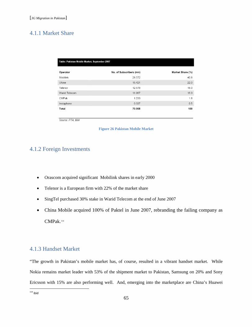
[3G Migration in Pakistan]
65
4.1.1 Market Share
Figure 26 Pakistan Mobile Market
4.1.2 Foreign Investments
• Orascom acquired significant Mobilink shares in early 2000
• Telenor is a European firm with 22% of the market share
• SingTel purchased 30% stake in Warid Telecom at the end of June 2007
• China Mobile acquired 100% of Paktel in June 2007, rebranding the failing company as
CMPak.114
4.1.3 Handset Market
“The growth in Pakistan’s mobile market has, of course, resulted in a vibrant handset market. While
Nokia remains market leader with 53% of the shipment market to Pakistan, Samsung on 20% and Sony
Ericsson with 15% are also performing well. And, emerging into the marketplace are China’s Huawei 114
ibid

[3G Migration in Pakistan]
66
Technologies and ZTE, helped by a price sensitive market. Indeed, the most popular handset models in
Pakistan do tend to be in the low-to-mid tier market with the following selling well – Nokia 1110/1112;
Samsung E250; Sony Ericsson K750i; and the Motorola RAZR V3.”115
Figure 27 Mobile handset market
4.2 The Internet
With Internet being one of the driving forces in 3G developments, the Internet demand in Pakistan would
play a significant role in answering questions regarding 3G migration. “Internet usage is growing all the
time in Pakistan and BMI predicted 17mn Internet users at the end of 2007, with penetration at 11%. And
this is despite the fact that ownership of PCs remains rare in Pakistan. Furthermore, a poor fixed-line
infrastructure suggests that dial-up usage is very common, resulting in very slow download speeds. The
increasing popularity of broadband services, matched by the determination of PTCL to improve the
standards of its Internet business is likely to change this in time. However, high costs of broadband
services in Pakistan mean that this change could be very slow, and BMI forecasts that penetration will
remain at below 1% until well into 2012. Given the phenomenal growth in recent years of Pakistan’s
115
Pakistan telecommunications report , Q1 2008, by BMI
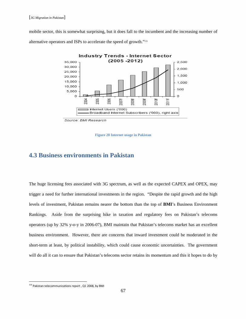
[3G Migration in Pakistan]
67
mobile sector, this is somewhat surprising, but it does fall to the incumbent and the increasing number of
alternative operators and ISPs to accelerate the speed of growth.”116
Figure 28 Internet usage in Pakistan
4.3 Business environments in Pakistan
The huge licensing fees associated with 3G spectrum, as well as the expected CAPEX and OPEX, may
trigger a need for further international investments in the region. “Despite the rapid growth and the high
levels of investment, Pakistan remains nearer the bottom than the top of BMI ’s Business Environment
Rankings. Aside from the surprising hike in taxation and regulatory fees on Pakistan’s telecoms
operators (up by 32% y-o-y in 2006-07), BMI maintain that Pakistan’s telecoms market has an excellent
business environment. However, there are concerns that inward investment could be moderated in the
short-term at least, by political instability, which could cause economic uncertainties. The government
will do all it can to ensure that Pakistan’s telecoms sector retains its momentum and this it hopes to do by
116
Pakistan telecommunications report , Q1 2008, by BMI

[3G Migration in Pakistan]
68
encouraging investment from the world’s largest handset manufacturers.”117 It is imperative at this point to
shed light on what it is that the region has to offer in that regard.
On the face of it, Pakistan has a much-improved business environment, as can be seen by the
evidence of considerable inward investment in the telecoms sector over the last few years. And
yet, Pakistan still lies nearer the bottom of BMI Ranking table in 11th position. On the one hand,
Pakistan’s regulator scores very well for its role in encouraging investment, and the market is
hugely competitive, offering huge potential for growth, not only in the mobile market, but also
high-speed Internet, both fixed and wireless. However, the country remains in political
difficulties and does not offer the most stable of markets, either politically or economically. On
the positive side, Pakistan’s telecoms sector currently contributes about 2% of the country’s GDP
and total revenues reached PKR236bn in 2006-2007. The sector received US$1.8bn of FDI in
the last fiscal year, accounting for 35% of total FDI in Pakistan. These are all figures that go to
suggest Pakistan’s telecoms sector is in great shape and offers the investor huge opportunities. So
much so that the government, having seen a number of carriers enter and transform Pakistan’s
mobile market in recent years, now aims to offer incentives for the manufacturers of handsets and
other telecoms equipment, to make Pakistan a popular manufacturing base.118
117
ibid 118
Pakistan telecommunications report , Q1 2008, by BMI

[3G Migration in Pakistan]
69
Figure 29
4.3.1 Pakistan among top 20 outsorucing Detonations
The paradox of instability in Pakistan on one hand and the rapid growth of technical expertise on the other
are surprising for many. As mentioned in a business week article by Rachael King published on June 4,
2009, Pakistan has become the 20th most attractive outsourcing destination, according to consulting
management firm A.T. Kearney. Even as concerns increase about Pakistan’s stability and the growing
displaced population due to ongoing military operations with the Taliban, the country made a significant
jump on A.T. Kearney’s 2009 Global Services Location Index released May 18. Pakistan went from #30
in 2007 to #20 in 2009.
“This rise in the ranks happened without much institutional support and lack of coherent policies. In my
opinion, this represents the very nature of Pakistani culture. Resilience and the will to carve out ways to
[3G Migration in Pakistan]
70
succeed is part of the Pakistani fabric. This is one of the many ways Pakistanis are answering the
challenges posed by the current security environment. Consider for example the upcoming gathering of
Pakistanis in Silicon Valley. One session is dedicated to discussion of how can entrepreneurship promote
development and stability in Pakistan?”
4.4 3G Market and Consumer
GSM world took over the country primarily due to the strong need for breaking PTCL’s monopoly, as
well as the unexpected popularity of voice on the go. It evolved and grew over time by penetrating the
rural and remote areas. Hence, demand was created for GSM by developing consumer bases that had
never had an access to any kind of communication service before. Back then, the initial era consisted of
high tariffs, expensive handsets, and limited mobility. The breakthrough occurred after the technology
matured and more players entered into the market; the former lead to cheaper user terminals and the later
to cheaper tariffs and more coverage. Coming back to the discussion in hand, 3G migration in Pakistan,
there is a world of possibilities upon which the region could embark. The market may not be present yet,
as the opponents of 3G would say with less demand for broadband services, but that in no way could be
taken as an indication of what the future might hold. One way to look at it is to look into applications and
services that 3G could enable for the region.
3G service types and data rates offered are discussed in detail in chapters 2 and 3. Irrespective of the
underlying technology, the consumer is only concerned with the applications offered and is oblivious to
the access method that the network uses to provide those services and data rates. What this implies is that
a technology’s success in any region is linked to the changes that it invokes and how those changes are
made accessible to the masses. The changes in this case will be triggered by applications.
[3G Migration in Pakistan]
71
4.4.1 Consumer Revolution in the Urban Areas
In the urban areas, the 3G talk is believed to be corporate centric. “It is often assumed that early adopters
will be corporate customers for 3G, but mobile multimedia- games, entertainment and the like are much
more consumer oriented than the buttoned down sober suited business people. Applications like VoIP,
Moving Images, File transfer , Downloading Software , Virtual Home Environment , Web Browsing,
Document Sharing/ Collaborative Working, Audio, Home Automation, Remote LAN Access, Electronic
Agents, Dynamic Authoring, Job Dispatch ,Electronic commerce, Vehicle Positioning etc. are few from
the current known possibilities and don’t limit brand new introduced in the future.”119
Audio
With 3G, MP3 files will be downloadable over the air directly to phone via a dedicated server. There are
numerous business models to allow both the network providers as well as the copyright owners of the
MP3 material to benefit financially.
VoIP
With 3G and higher rate 2.5G, technologies such as EDGE and VoIP will be available for the first time on
mobile phones. VoIP can be used as an alternative to regular service but is not a replacement for standard
voice services since VoIP services are bandwidth demanding.
Still Images
Still images such as photographs, pictures, letters, postcards, greeting cards, presentations, and static web
pages can be sent and received over mobile networks just as they are across fixed telephone networks.
Once captured, images can then be sent directly to Internet sites, allowing near real-time desktop
publishing.
119
Yes to 3G

[3G Migration in Pakistan]
72
Moving Images
Sending moving images in a mobile environment has several vertical market applications including
(monitor sensor triggered) monitoring parking lots or building sites for intruders or thieves and sending
images of patients from an ambulance to a hospital. Videoconferencing applications, in which teams of
distributed salespeople can have a regular sales meeting without having to go to a particular physical
location, is another application for moving images that is similar to the document sharing/ collaborative
working applications reviewed below.
Virtual Home Environment
A service that simply lets customers have seamless access with a common look and feel to their services
from home, office, or on the move and in any city as if they were at home. VHE is, therefore, aimed at
roamers (a small subset of total mobile phone users).
Electronic Agent
Electronic agents are defined as "mobile programs that go to places in the network to carry out their
owners' instructions. They can be thought of as extensions of the people who dispatch them. Agents are
self-contained programs that roam communications networks delivering and receiving messages or
looking for information or services." Orange in the UK has a vision which expects that within ten years,
our mobiles will be waking us up, reading our emails, ordering our groceries, and telling us the best route
to work, reminding us, and translating our conference calls.
Downloading Software
In the twenty-first century, software will increasingly be downloaded electronically from the Internet
rather than purchased as boxed products in stores. Downloading software has several advantages because
it is environmentally friendly (no packaging to throw away or store), quick and convenient (downloadable

[3G Migration in Pakistan]
73
products are delivered direct to your computing device in minutes) and value for money (you pay no
delivery charges).120
4.4.2 Consumer Revolution in the Rural Areas
For a developing country like Pakistan, the biggest challenges in the rural areas are health and education.
There have been numerous economic and social claims that support the idea of revolution via changing
these conditions. 3G holds the potential for providing means in order to bring about those changes.
Mobiles and Healthcare: Telehealth and Telemedicine Trends
Cell phones may have changed the way people communicate in the developed world, but in developing
countries they’re going far beyond simple communication to bring new opportunities to areas that sorely
need them.
1. An example is the research at the Next Generation Intelligent Networks Research Center of FAST
University, Islamabad. Their work on “Remote Patient Monitoring System” with Focus on
Antenatal Care is funded by the National ICT R&D fund, Government of Pakistan, over the
period of three years (2008-2010). The primary objective of this project is to develop a reliable,
efficient, and easily deployable remote patient monitoring system that can play a vital role in
providing basic health services to the remote village population of Pakistan at their door step.
120 yes to 3G
[3G Migration in Pakistan]
74
2. A Pakistani researcher Jahanzeb Sherwani did doctoral-level research at CMU about using speech
recognition with local languages to collect information regarding rural health care. Speech
recognition is, he believes, the equalizer, the ultimate enabler. It doesn’t matter if you are
illiterate or if you speak a different language.
3. Due to a global shortage of some 4.4 million healthcare professionals, as estimated by the World
Health Organization, many rural health centers in poor regions depend largely on community
health workers who travel among clinics and villages. Due to limited facilities and the huge areas
covered by them, it is often too late to bring back help to the people in need. Launched in
February, FrontlineSMS:Medic aims to improve matters using FrontlineSMS, a free, open-source
software program that enables large-scale, two-way text messaging using only a laptop, a GSM
modem, and cell phones. Working with donations collected through Hope Phones, the initiative
places a laptop running FrontlineSMS in a central clinic and then distributes cell phones to
community health workers. Workers are trained in sending text messages to hospital staff to
request drug dosing information or treatment instruction, for example, or provide status updates
on a particular patient. Modified camera phones, meanwhile, can be used to analyze blood and
sputum samples and perform critical diagnostics for conditions including HIV/AIDS,
tuberculosis, and malaria. In a recent, six-month pilot test of the system at a hospital in Malawi,
150 patients received emergency care, and community health workers saved 1,000 hours of travel
time—allowing them to visit more patients.The number of people being treated for tuberculosis
doubled, and the hospital saved USD 3,500 worth of fuel, freeing up funds to purchase more
medication. Operating the system, meanwhile, requires an investment of just USD 500, according
to an article in the Guardian.
4. Of course, when it comes to developed countries, there is a lot of emphasis on reducing cost and
providing connected services whereby automation and intelligence can make devices and testing
smart. Here is ATT’s vision for medical remote monitoring:
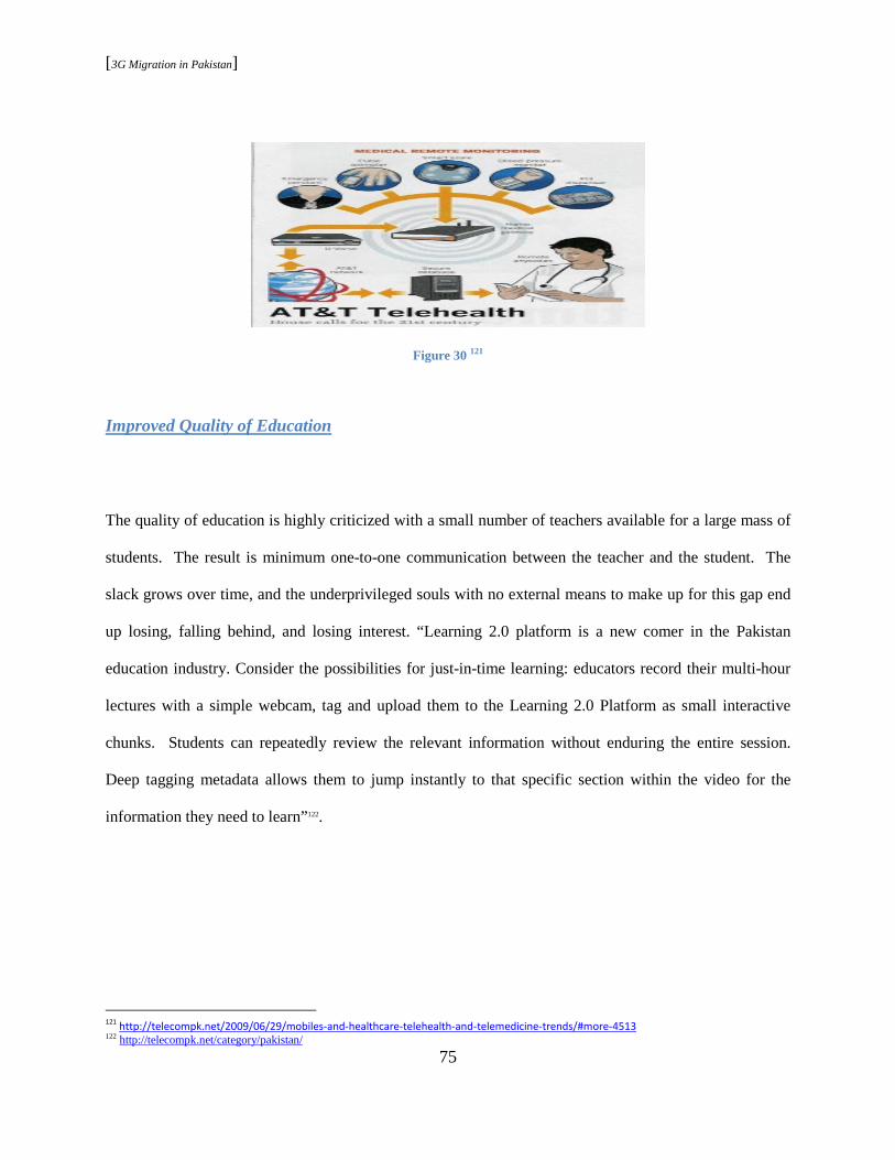
[3G Migration in Pakistan]
75
Figure 30 121
Improved Quality of Education
The quality of education is highly criticized with a small number of teachers available for a large mass of
students. The result is minimum one-to-one communication between the teacher and the student. The
slack grows over time, and the underprivileged souls with no external means to make up for this gap end
up losing, falling behind, and losing interest. “Learning 2.0 platform is a new comer in the Pakistan
education industry. Consider the possibilities for just-in-time learning: educators record their multi-hour
lectures with a simple webcam, tag and upload them to the Learning 2.0 Platform as small interactive
chunks. Students can repeatedly review the relevant information without enduring the entire session.
Deep tagging metadata allows them to jump instantly to that specific section within the video for the
information they need to learn”122.
121
http://telecompk.net/2009/06/29/mobiles-and-healthcare-telehealth-and-telemedicine-trends/#more-4513 122 http://telecompk.net/category/pakistan/
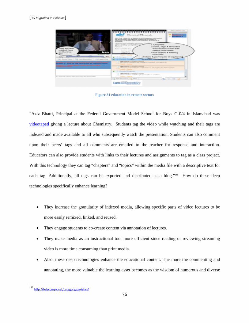
[3G Migration in Pakistan]
76
Figure 31 education in remote sectors
“Aziz Bhatti, Principal at the Federal Government Model School for Boys G-0/4 in Islamabad was
videotaped giving a lecture about Chemistry. Students tag the video while watching and their tags are
indexed and made available to all who subsequently watch the presentation. Students can also comment
upon their peers’ tags and all comments are emailed to the teacher for response and interaction.
Educators can also provide students with links to their lectures and assignments to tag as a class project.
With this technology they can tag “chapters” and “topics” within the media file with a descriptive text for
each tag. Additionally, all tags can be exported and distributed as a blog.”123 How do these deep
technologies specifically enhance learning?
• They increase the granularity of indexed media, allowing specific parts of video lectures to be
more easily remixed, linked, and reused.
• They engage students to co-create content via annotation of lectures.
• They make media as an instructional tool more efficient since reading or reviewing streaming
video is more time consuming than print media.
• Also, these deep technologies enhance the educational content. The more the commenting and
annotating, the more valuable the learning asset becomes as the wisdom of numerous and diverse
123
http://telecompk.net/category/pakistan/
[3G Migration in Pakistan]
77
interested parties add layers of collective intelligence to the video. Furthermore, specific moments
of time within these videos can be instantaneously identified and retrieved with the Learning 2.0
Platform search engine.
• Consider the opportunity for enhancing the quality of education in Pakistan by harnessing
thousands of video lectures produced by the top teachers throughout the country. This digital
archive could be searched as indexed meta data by key words within the annotations. Not only
would this video library complement and extend traditional learning, but it would also scale
giving millions of student’s access to a quality education.124
Distance Learning
Ghost’s schools are fairly common in Pakistan. These schools exist on paper only. Reasons are more
than a few but usually revolve around the distance a teacher has to commute to get to these places and the
effort required by them in relation to the salaries they receive. With the 3G infrastructure in place and the
right applications used, a foundation could be laid to provide quality education in remote villages and
towns. The West is already using numerous custom-made tools to provide online degrees. For Pakistan,
the change has to be gradual and patient. It requires additional resources for educating end user to use
these tools in an optimum fashion, to provide means to access these tools (desktops connected to the
world with 3G) , yearly plans to implement and monitor such system, acceptance by the HEC ( higher
education system), etc. Bottom line; however, is to use 3G as the last mile for making this vision a
possibility.
124
http://telecompk.net/category/pakistan/

[3G Migration in Pakistan]
78
4.4.3 Applications Impact
3G is just an evolution of current telecom services offered by cellular operators. But the missing link of
applications and content conversion has the potential to convert this evolution into a revolution for
Pakistan. The important factor is how and when the region would embrace this revolution.
4.5 Future Forecast of Mobile Users
The following is a summary of the expected growth in mobile users by BMI:
Figure 32 Wireless Statistics
[3G Migration in Pakistan]
79
“Growth will slow down partly as the market becomes saturated and partly as it reaches less accessible
parts of the country. BMI forecasts that there will be 100mn mobile subscribers at the end of 2008, and
that by the end of our forecast period in 2012, there should be more than 135mn customers, accounting
for a penetration rate of around 78%. This would still represent an annual average growth rate of 8%
between 2008 and 2012. With regards to our 3G forecasts, it seems likely that the PTA will run an auction
for three licenses no earlier than towards the beginning of 2008, with commercial deployment either later
that year, or maybe early in 2009. With GSM the main mobile technology in use in Pakistan, the preferred
3G technology would be UMTS, although China Mobile may be tempted, if it were to win a license, to
usher in its homegrown TD-SCDMA standard.”
[3G Migration in Pakistan]
80
Chapter 5 Regulation
5.1 Regulation Enabling the Business Environment
In the current diverse and dynamic world of Telecommunications, regulation plays far more vital role
then mere allocation of frequency and technology. In research by ETSI, the key determinants of the
success of 3G auctions were how well the auctions attracted entry and discouraged collusion. There is no
one size fits all formula! The regulatory body needs to implement policies to overcome obstacles to
growth and profitability (custom duties, handset sales taxation, service taxation, competition, low cost
interconnect environment), compliance to internationally accepted stands, alignment with internationally
accepted spectrum bands and allocations, and an independent regulatory body backed up by a robust legal
system.
5.2 Pakistan Telecommunication Authority
The telecommunications sector in Pakistan is regulated by the PTA, which was established in 1996
following the passage of the Pakistan Telecommunication (Re-organization) Act into the statute book.
PTA’s functions include:
To regulate establishment, operation, and maintenance of telecoms systems and services in
Pakistan;
To receive and dispose of applications for the use of radio-frequency spectrum;
To promote and protect the interests of users of telecoms services in Pakistan;
[3G Migration in Pakistan]
81
To promote the availability of a wide range of high quality, efficient, cost effective, and
competitive telecoms services in Pakistan;
To promote the modernization of telecoms systems and services;
To investigate and adjudicate complaints and claims made against licensees arising out of alleged
contravention of the provisions of the above Act;
To make recommendations to government on policies with respect to international telecoms, the
provision of support for participation in international meetings and arrangements to be executed
in relation to the routing of international traffic and accounting settlements.125
“The PTA has helped Pakistan’s telecoms industry to attract rising levels of FDI both from existing
operators looking to enhance networks, and from foreign companies looking to enter Pakistan’s telecoms
market via acquisition. In the year 2006 alone, there were five major international acquisitions.”126
5.3 3G Licenses
The 3G license auction has been delayed in Pakistan for more than three years now. “PTA initially did
suggest that it would auction three 3G mobile licenses by the end of 2007.”126 Later on, the news predicted
auction by last quarter of 2008. Dated 2008, Shehzada Alam Malik of Pakistan Telecommunication
Authority said, “we will issue three 3G licenses to the already operational cell phone companies in the
country for which bidding is expected during September to December this year. Almost all of these
companies working in the country are having shown an interest in the new license.” 127 “Indeed, the PTA
has recommended that the licensing of 3G services be delayed and that the mobile data market in Pakistan
125 Pakistan telecommunications report , Q1 2008, by BMI 126 Pakistan telecommunications report , Q1 2008, by BMI 127 http://www.itu.int/osg/spu/ni/3G/resources/licensing_policy/index.html

[3G Migration in Pakistan]
82
is insignificant. However, this is likely to remain the case until 3G services are launched, and 3G mobile
telephony could suffer at the hands of WiMAX, which Mobilink and Ufone are already working on
launching imminently.”
5.4 Issues Regarding 3G Licenses
Regardless of PTA’s effort and willingness towards 3G licenses, it has been a three year delay in 3G
license allocations. There are two major factors, one at the government end and the second more towards
the operator strategies.
5.4.1 MoITT
PTA has studied the case for 3G in Pakistan and put forward its recommendations to the Ministry of
Information Technology and Telecom (MoITT). MoITT has, in turn, prepared and submitted its
recommendations to the Cabinet for deliberations and approval in April 2009. Unfortunately, there is no
Minister assigned to MoITT and hence the case is probably not being followed up as necessary. PTA
would be unable to initiate any allocations prior to a legal affirmation by MoITT. So, until the cabinet
makes some decisions, things will not move forward. In case the cabinet accords its approval, then PTA
is more likely to publish the relevant legislation, regulatory processes, and requirements. In the
meantime, PTA ought to be working on these, but probably their work is not available to the public at
large.
[3G Migration in Pakistan]
83
5.4.2 LTE
Pakistan region, currently, is facing the inevitable dilemma of a new technology superseding an old one.
The delays have led to the case where W-CDMA might be overwritten by LTE’s new air access
techniques. Hence, the fast approaching arrival of LTE has adopted different strategists. The result is
operator’s hesitance in investing huge capital in an older technology. Hence, the challenge is not only
when to allow technology implementation but also what technology should be allowed.
5.5 UMTS900
Another important task for PTA at this point is to consider the option of frequency refarms. The idea of
frequency reuse for higher data rates led to the introduction of UMTS-900. “There is a very strong
business case and momentum for deploying UMTS900 (WCDMA-HSPA) systems in the 900 MHz band,
generally used today by GSM networks, to help operators efficiently extend voice, data and mobile
broadband services coverage by leveraging the advantages of lower frequencies.”128
“Of course, there is no reason why WCDMA could not be deployed at other frequencies. In fact, the use
of other frequencies may well be necessary in some countries. For instance, the frequency bands defined
previously overlap significantly with frequencies used for PCS in North America. Therefore, in North
America, it will be necessary to move some existing users from the PCS band and/or acquire a new
spectrum in some other band. The movement of existing PCS users is likely only to happen when a given
carrier that wants to implement UMTS already has an existing PCS system and uses some of the spectrum
128
GSM/3G Market/Technology Update
[3G Migration in Pakistan]
84
for UMTS. The net result for such an operator will, of course, be limited spectrum for both PCS and
UMTS.”129
5.5. 1 UMTS900 Technical Specifications
Technical specifications for WCDMA-HSDPA in the 900 MHz band (UMTS900) were completed by
3GPP in December 2005. The 900 MHz band, denoted as Band Class VIII, is defined as paired bands in
the range 880 to 915 MHz (uplink), and 925 to 960 MHz (downlink). Similar benefits and efficiencies are
obtained using WCDMA-HSPA in the 850 MHz band.
5.5.2 UMTS900 Benefits
Providing full coverage using 2100 MHz would be too expensive, impractical and take too long
for many mobile network operators. Radio propagation path-loss at 900 MHz is much lower. For
the same service offering and coverage, the number of cell sites required using 900 MHz is
significantly lower compared to that needed for 2100 MHz, with reduced rollout time. Indoor
coverage is also improved with 900 MHz. UMTS900 can complement 2100 MHz deployments
to improve coverage, reduce CAPEX and OPEX, improve Quality of Service and enhance the
user experience. UMTS900 network operators can provide HSPA mobile broadband services in a
very cost-efficient way. GSM operators can re-use existing network assets including antennas
and network management systems. UMTS900 delivers the same data rates as UMTS2100, with
fewer than half the number of cell sites. Operators report increases in traffic (especially data) and
129
3g wireless network

[3G Migration in Pakistan]
85
revenue growth where 3G is offered. All 3G applications can be provided and used cost
efficiently over much larger area.130
UMTS900 brought 3G and mobile broadband services more cost effectively to outside the cities.
• Same coverage with 2 to 3 times fewer sites vs. 2100 MHz
• Significantly lower cost (CAPEX and OPEX)
• Allows operators to provide mobile broadband more cost efficiently
• All existing 3G applications can be provided and used cost efficiently over much larger
geographical area
• Ideal for rural and suburban areas as the first step
• Same data rates using 900 MHz as for 2100 MHz
• Same cell radius for packet data services as GSM900 voice optimizes coverage and performance
• re-use GSM900 sites/spectrum to fill in areas not covered by 2100 MHz
• Improves Quality of Service and the user experience
• Drives ARPU growth in 3G services
• Indoor coverage also improves using 900 MHz; helps in urban areas131
It is imperative at this point to highlight a possible key enabler for 3G in Pakistan. “Regulatory approval
is required to clear the way for WCDMA-HSPA 900 MHz deployments in a number of markets. An
important political development in Europe concerning regulation of the 900 MHz was announced on
March 24, 2009, which would remove restrictions on how the band is used by repealing the 1987 GSM
130
GSM/3G Market/Technology Update 131 UMTS900 Market Overview Alan Hadden, President Global mobile Suppliers Association

[3G Migration in Pakistan]
86
Directive. This is a clear signal to all regulators to prepare the path in their respective markets for a new
wave of HSPA deployments in the 900 MHz band. Some countries must re-arrange band allocations in
order to enable GSM and UMTS900 in 900 MHz spectrum.”132
132 GSA_Information_Paper_UMTS900

[3G Migration in Pakistan]
87
Chapter 6 - Issues and Challenges
Pakistan today stands at grounds similar to the West a decade ago. Hence, it is imperative to mention the
industry views in the West prior to the launch of 3G.
“As with all new technology standards, there is uncertainty and the fear of displacement. Third
Generation (3G) mobile is topical and contentious for several reasons:
• Because the nature and form of mobile communications is so radically changed, many people do
not understand how to make money in the non voice world, and do not understand their role in it
• 3G licenses have been awarded around the world, in many cases at huge cost, necessitating that
existing mobile communications companies in the 2G world think about and justify their
continued existence.
• 3G is based on a different technology platform- Code Division Multiple Access (CDMA)- that is
unlike the Time Division Multiple Access (TDMA) technology that is widely used in the 2G
world.
• The US, Japanese and European mobile players all have different technology competences and
are now unified in this single standard- the separate wireless evolution paths and European
wireless leadership are thereby challenged
• Japanese network operators will be the first to implement 3G networks in the year 2001, and
Japanese terminal manufacturers, who have not had much market share outside their home
market, will be first with 3G terminals
• Many industry analysts and other pundits have questioned the return on an investment in 3G
technology- questioning whether network operators will be able to earn an adequate return on the
capital deployed in acquiring and rolling out a 3G network.

[3G Migration in Pakistan]
88
• Many media and Internet companies have shown a strong interest in using 3G technologies as a
new channel to distribute their content, opening the opportunity for new entrants and new
partnerships and value chains.”133
6.1 3G Issues and Challenges in Pakistan
With no changes in the technology itself, the core challenges are more or less the same. However, the
choice and time of technology, when translated into the region, needs and expectations present the
following picture:
6.1.1 Regulatory
• The biggest issue encountered by the region today turns out to be neither technology nor the
market but the regulatory decisions. 3G License allocation has been delayed for almost three
years. PTA efforts to educate the operators (investors) on 3G required parallel work on setting
grounds for its implementation. Unfortunately, the latter didn’t become a reality, causing doubt
and uncertainty. The operators were reluctant due to the high cost associated with the purchase of
new spectrum. By the time a trust factor was established, LTE emerged as a more promising
technology over UMTS due to its low cost/pit. Hence, a journey that began at the crossroad of
Yes or No to 3G is now at a similar point of either UMTS now or wait for LTE. The result in
both cases is a delay which may lead to more complications in making 3G a reality in the region.
133
YES 2 3G” - White Paper www.mobilestream.com
[3G Migration in Pakistan]
89
• Another important factor to mention here is overlapping frequency bands between the operators
and the defense authorities.
• Tax rate on services, handsets, and equipment is what needs to be agreed upon by PTA as well as
the service providers. One-sided forced figures can discourage innovation and success by
limitations imposed.
• The high cost associated with the 3G in general is now causing a shift towards infrastructure
sharing among major competitors around the globe. PTA would have to provide just and
promising strategies in this regard in the times to come.
6.1.2 Market and Consumer
• 3G has been often interpreted as mobile broadband anywhere and anytime. Internet being the
most commonly used application has lead to 3G success in Europe and USA. The data usage in
Pakistan has been a showstopper for most operators. BMI statistics of 35 million Internet and 2.5
million broadband consumers in a population of 160 million by the end of 2012 is indeed a
critical fact.
• The data usage merit for 3G is a fact, but as discussed is article 4.4, the region bears high
potential for supporting the world of 3G. In an underdeveloped country like Pakistan, 3G
possesses the necessary traits to bring economic and social revolution. The change expected is
gradual, but the outcome would be long lasting and promising.
• Foreign investment did play a crucial role in boosting telecommunication industry in Pakistan.
However, recent political instability has adversely affected 3G roll out in the region. 3G
spectrum fees went down since its introduction. An analyst observed a decline in the 3G license
fees around the globe since 2001. But for a developing country like Pakistan, the figures could
never be too low, and foreign investments would always be the financial backbone. Referring to

[3G Migration in Pakistan]
90
article 4.1.2 in chapter 4, the region does have a strong share of overseas investment, but the
challenge now is to retain and increase those share.
• Last mile connectivity is what defines any technological success. Consumer access to the
services in case of 3G would eventually be the handset industry. Figure 4.2 depicts Nokia
dominance in the mobile market. What that means is a high customer confidence in Nokia
handsets within the region. Considering the availability of Nokia 3G phone sets in international
market, this may ease the transition from 2 to 3G at the customer end. But at the same time, it
posts threats of overshadowing and limiting consumer exposure to a more diverse environment.
6.1.3 Technology
• It has been almost a decade since the launch of the first 3G network. UMTS-WCDMA’s maturity
and success is confirmed by its commercial deployment in 115 countries with 264 operators.
Hence, there is no doubt about that. In fact, the technology further evolved as discussed in
chapter three of this paper, and the result is the following fact sheet by GSA:
Figure 33 GSA market survey

[3G Migration in Pakistan]
91
• The next in line candidate is LTE. The theoretical findings for this technology, as discussed in
chapter three of this paper, are promising. On practical grounds, as per the research by GSA,
commercial networks would be available somewhere near the end of 2009.134 So the success of
LTE in various environments and industries has yet to be observed. It’s a risk that regions with
established 3G networks are more inclined to take. For them, with an already established base of
3G consumers and 3G revenue pouring in, LTE is worth the risk. However, for a region like
Pakistan, still to embark into the world of 3G, LTE at this point in time fails to provide
guarantees. Hence, immature technology popularity poses significant threats as to when and how
3G might become a reality.
• Technological myth, as discussed in chapter two, has had a great influence on the choices that are
visible to interested candidates. UMTS-WCDMA is largely viewed as sole enabler of 3G. On a
more generic level, purchase of new spectrum is usually referred to as an enabler for 3G. Hence
the cost associated with new spectrum is what discourages investors. The result is an industry
that is facing major delays in 3G, not due challenges faced by the technology but due to the myth
associated with that technology.
• EDGE-2 is a highly neglected technology.
134 www.gascom.com

[3G Migration in Pakistan]
92
Chapter 7 Transition Model
(Preface Extract )…………Innovation and progress is indeed a catalyst that triggers change and change in
this case may be an upgrade, evolution or revolution in technology. The question, which technology and
where or how is still unanswered. Some of the most important issues include, market readiness, business
issues (e.g., pricing, market segmentation), service issues (e.g., coverage, service portfolio and QoS) and
technical challenges (e.g., spectrum availability, maturity of technology, and availability of proper user
terminals). This thesis will interpret such issues in regards to the expected transition in Pakistan and will
justify a migration model highlighting the inevitable challenges lined up for region’s future.
7.1 Model Guidelines
• The core idea behind this model stems from the notion that technology alone is not enough to
penetrate an industry successfully. In terms of technology itself, an immature technology faces
failure threats due to the unseen challenges lying ahead. On the other hand, an overly mature
technology is shadowed by succeeding evolutions in its line. However, the success merit goes
beyond technology as factors like regulation, market, and consumers play significant roles in
concluding response within a certain region. These are the combined catalysts that define need
and readiness of an industry as recipient. Together, they can translate failure in one region into
success in another and vice versa.
• From a business perspective, it is the integration of an undeveloped model into an overly
developed environment or that of a highly advanced model in a poor one. In the former case, the
outcome is highly raised merit expectations that are impossible to meet. In the later case, the
[3G Migration in Pakistan]
93
outcome is a non-competent product placed among highly efficient ones. The result in both cases
is a chaos.135
• “Third generation (3G) systems promise faster communications services, including voice, fax and
Internet, anytime and anywhere with seamless global roaming. 3G is the term used to describe
the latest generation of mobile technology which provides enhancements to voice
communications and data connectivity including wireless access to the Internet, mobile
applications and multimedia content.”136 It is crucial to understand that 3G is indeed a next
generation network technology. What that implies is how these services are made available to the
consumer is transparent to them. The access schemes approved by ITU are there to provide last-
mile connectivity. The applications and tools running on top of any 3G network require certain
bandwidth and connectivity but are in no way dependant on how these requirements are fulfilled.
• Purchase of a new spectrum myth, associated with 3G, has been challenged by technologies like
EDGE2, UMTS 900, and UMTS850 and to some extend LTE as well. The commercial standing
and success of these networks do confirm that purchase of a new spectrum is not the only route to
3G.
• Is data-rate the only driver? In recent research into the use of unified communications and
collaboration, Nemertes Research found that enterprise IT executives are concerned about the
wireless standards. But why? Latency and coverage trump raw bandwidth! Carriers need to
look at this evolution from the standpoint of the business customer. Transfer rates aren't always
the issue. In many cases, considerations such as latency and coverage are more important than
raw bandwidth. What many businesses are realizing is that the wireless standard and where it is
135 Project Management 136 White Paper from the UMTS Forum Mobile Broadband Evolution: the roadmap from HSPA to LTE February 2009
[3G Migration in Pakistan]
94
being deployed can have a profound impact on the utility of a wireless-enabled mobility
application.137
• The migration to a new technology is more successful when changes are more consumer centric
than operator centric. In other words, the flow of change ought to be from the consumer end
towards the service provider and not vice versa. It is the end-user demand or expected market
growth that defines the migration path.
7.2 Wireless Migration from an Operator’s Perspective
“The existing wireless operators today regardless of the frequency band or existing technology deployed
have or are making very fundamental decisions as to which direction in the 3G evolution they will take.
The decision on 3G technology will define a company's position in the marketplace for years to come.
Since the platforms to pick from utilize different access technologies, they are by default not directly
compatible. The utilization of different access technologies for the realization of 3G also introduces
several interesting issues related to the migration from 2G to 3G. The migration path from 2G to 3G is
referred to as 2.5G and involves an interim position for data services that are more advanced than 2G, but
not as robust as the 3G envisioned data services.”138 Some of the migration strategies for an existing
operator involve:
Overlay: The overlay approach typically involves implementing the 2.5 technology over the
existing 2G system and then implementing 3G as either an overlay or in a separate part of the
radio frequency spectrum where they are allocated, spectrum segmentation.
137
http://searchtelecom.techtarget.com/tip/0,289483,sid103_gci1319015_mem1,00.html?offer=briefcase&ShortReg=1&mboxConv=searchTele
com_RegActivate_Submit& 138
3G Wireless Networks
[3G Migration in Pakistan]
95
Spectrum segmentation: The choice of whether to use an overlay or spectrum segmentation is
naturally dependent upon the technology platform that is currently being used, 2G, the spectrum
available, the existing capacity constraints, and marketing. Marketing is involved with the
decision because of the impact to the existing subscriber base and services that are envisioned to
be offered.139
7.3 Wireless Migration from a Consumer’s perspective
Unless consumers are eager to adopt mobile broadband services, the new networks and pricing regimes
will have little impact. Consumer expectations and requirements for mobile broadband around the globe
have evolved dramatically in recent years as users become accustomed to high speed access with fixed
broadband. In Pakistan, the demand is more social and economical than personal. The opponents of 3G
present the lack of notebooks and exposure to Internet as reasons behind limited data demand. The claim,
although true today, is more likely to become obsolete in the future. The health and education scenarios
provided in chapter four, if supported well by the government, regulators, and service providers, can bring
huge data volumes into the rural areas.
In the urban parts too, the more educated class can take advantage of the diverse 3G services as discussed
in this paper. Operators are accustomed to having control over new types of services coming onto their
networks, but now \ services are driven by consumers and web companies. No one predicted the
enormous popularity of virtual worlds, geospatial services, or instant messaging. Few anticipated the
deployment, use, and impact of social networking applications. Multiple new forms of communication
have materialized as people discover and explore the benefits of social networking sites and the power of
instant online communication. These developing communication ‘personas’ are currently trapped to
139 3G wireless network
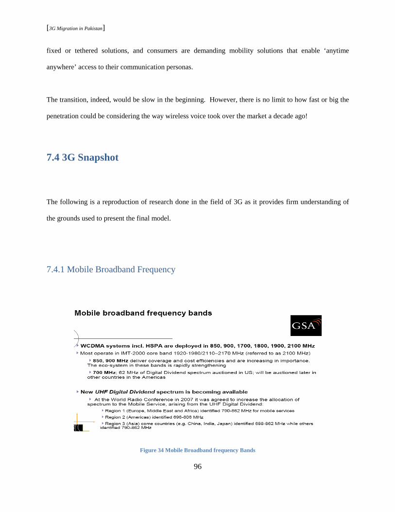
[3G Migration in Pakistan]
96
fixed or tethered solutions, and consumers are demanding mobility solutions that enable ‘anytime
anywhere’ access to their communication personas.
The transition, indeed, would be slow in the beginning. However, there is no limit to how fast or big the
penetration could be considering the way wireless voice took over the market a decade ago!
7.4 3G Snapshot
The following is a reproduction of research done in the field of 3G as it provides firm understanding of
the grounds used to present the final model.
7.4.1 Mobile Broadband Frequency
Figure 34 Mobile Broadband frequency Bands
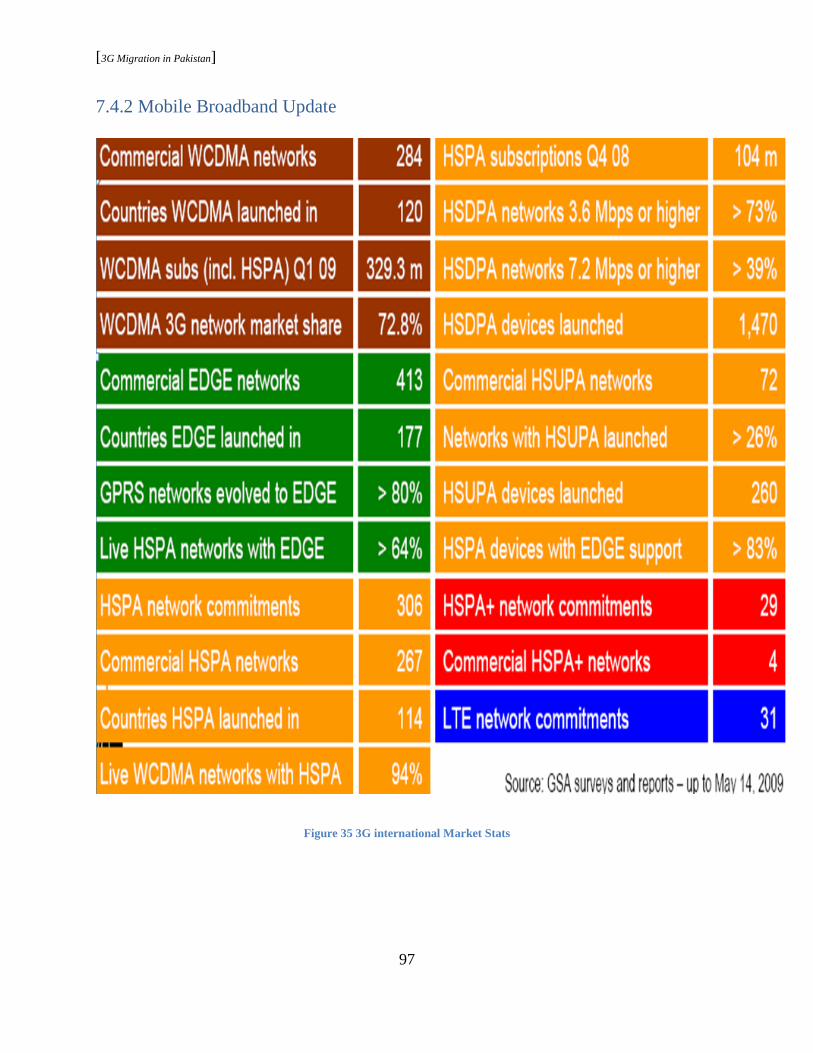
[3G Migration in Pakistan]
97
7.4.2 Mobile Broadband Update
Figure 35 3G international Market Stats
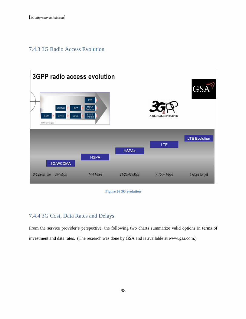
[3G Migration in Pakistan]
98
7.4.3 3G Radio Access Evolution
Figure 36 3G evolution
7.4.4 3G Cost, Data Rates and Delays
From the service provider’s perspective, the following two charts summarize valid options in terms of
investment and data rates. (The research was done by GSA and is available at www.gsa.com.)
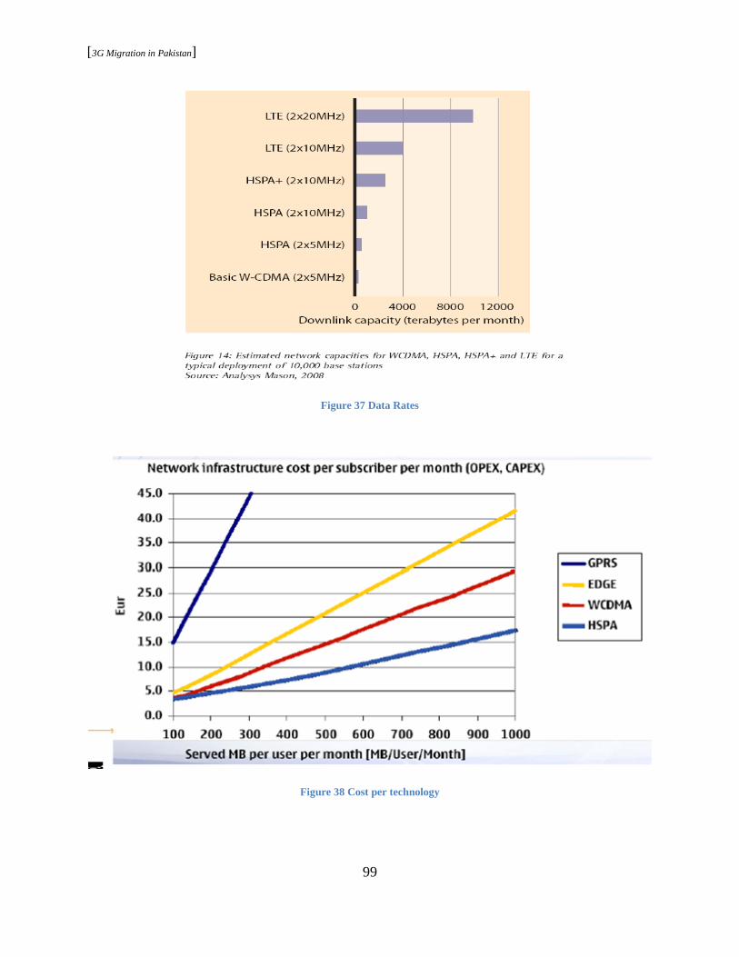
[3G Migration in Pakistan]
99
Figure 37 Data Rates
Figure 38 Cost per technology

[3G Migration in Pakistan]
100
Note: LTE, not shown in this picture, offers less cost per megabyte when compared with HSPA. The
massive increase in capacity comes at a lower cost per bit. The cost per megabyte could drop by a factor
of 3, from Euro 0.03 for HSPA (2x5 MHz) to Euro 0.01 for LTE (2x5 MHz), according to the Analysis
Mason study.
Figure 39 The evolution path for 3G
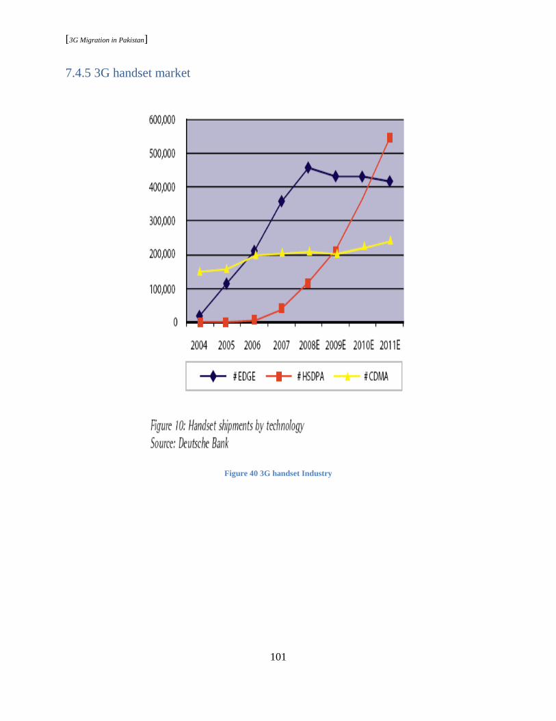
[3G Migration in Pakistan]
101
7.4.5 3G handset market
Figure 40 3G handset Industry
[3G Migration in Pakistan]
102
7.5 Migration Model
The migration, driven by the market, consumer, and the regulators, can be best visualized in a series of
steps. When categorized broadly, it would be:
• Evolution
• Revolution
7.5.1 Evolution-Evolved EDGE
Going back to the model guidelines, the change ought to be consumer centric for 3G success. It is not the
high data rates alone but regulation, consumer, and market readiness all together that need to be looked
into. The operator’s reluctance to make a high capital investment due to concerns of limited data demand
is valid. However, referring to the discussion in chapter 4, the region potential for high data demand in
the times to come could be anything but revolutionary. Evolved EDGE provides means to increase that
demand over time with minimum changes in the existing infrastructure. In the shorter run, it can bridge
and enhance user’s exposure to the world of 3G. The shift would be gradual, but the impact would be
more intense when higher data rates are introduced later on.
“Current EDGE peak data rates of 300 kbps cannot cope with the data rates of 7.2 Mbps provided by
WCDMA/HSPA networks. Introduction of new modulation schemes, e.g., 32 QAM and higher symbol
rate boost data rates up to 118.4 kbps per timeslot. In combination with dual downlink carrier, mobile
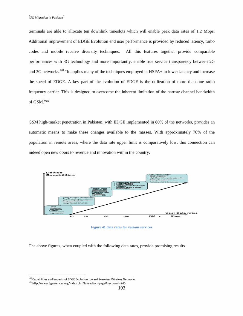
[3G Migration in Pakistan]
103
terminals are able to allocate ten downlink timeslots which will enable peak data rates of 1.2 Mbps.
Additional improvement of EDGE Evolution end user performance is provided by reduced latency, turbo
codes and mobile receive diversity techniques. All this features together provide comparable
performances with 3G technology and more importantly, enable true service transparency between 2G
and 3G networks.140 “It applies many of the techniques employed in HSPA+ to lower latency and increase
the speed of EDGE. A key part of the evolution of EDGE is the utilization of more than one radio
frequency carrier. This is designed to overcome the inherent limitation of the narrow channel bandwidth
of GSM.”141
GSM high-market penetration in Pakistan, with EDGE implemented in 80% of the networks, provides an
automatic means to make these changes available to the masses. With approximately 70% of the
population in remote areas, where the data rate upper limit is comparatively low, this connection can
indeed open new doors to revenue and innovation within the country.
Figure 41 data rates for various services
The above figures, when coupled with the following data rates, provide promising results.
140
Capabilities and Impacts of EDGE Evolution toward Seamless Wireless Networks 141
http://www.3gamericas.org/index.cfm?fuseaction=page§ionid=245
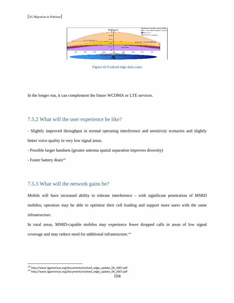
[3G Migration in Pakistan]
104
Figure 42 Evolved edge data rates
In the longer run, it can complement the future WCDMA or LTE services.
7.5.2 What will the user experience be like?
- Slightly improved throughput in normal operating interference and sensitivity scenarios and slightly
better voice quality in very low signal areas.
- Possible larger handsets (greater antenna spatial separation improves diversity)
- Faster battery drain142
7.5.3 What will the network gains be?
Mobile will have increased ability to tolerate interference – with significant penetration of MSRD
mobiles; operators may be able to optimize their cell loading and support more users with the same
infrastructure.
In rural areas, MSRD-capable mobiles may experience fewer dropped calls in areas of low signal
coverage and may reduce need for additional infrastructure.143
142
http://www.3gamericas.org/documents/evolved_edge_update_04_2007.pdf 143
http://www.3gamericas.org/documents/evolved_edge_update_04_2007.pdf
[3G Migration in Pakistan]
105
7.5.4 Market and Commercial Standing
Following the Rel-7 industry standardization, Ericsson and Nokia Siemens Networks are among those
companies committed to launch EDGE evolution as a software upgrade of existing infrastructure in 2009.
RIM has also endorsed EDGE evolution.144
Nortel and partner Prisma Engineering have announced end-to-end Evolved EDGE communication. The
company intends to demonstrate the solution at Mobile World Congress that will include live video
streaming over Evolved EDGE and LTE. This demonstrates the coupling of these technologies to deliver
network-wide service continuity. A simple software upgrade for an existing EDGE network enables
Evolved EDGE and can more than double the spectral efficiency. The company adds that in practice these
enhancements deliver an improved end-user experience and access a full range of mobile applications
including VoIP, gaming, Web browsing, e-mail, and video streaming.145
Evolution
Evolution provides ease in migration towards 3G by bringing data rates at the minimum end of ITU
specifications at lower costs but is indeed not comparable to the advances in 3G. Revolution is the logical
next step in moving towards the world of wireless broadband. However, what technology to choose from,
the range discussed in chapter two and three, is still an unanswered question.
144
http://www.3gamericas.org/index.cfm?fuseaction=page§ionid=245 145
http://www.astricon.net/topics/broadband-mobile/articles/20436-nortel-announces-new-evolved-edge-communication-technology.htm

[3G Migration in Pakistan]
106
7.6 Revolution
7.6.1 LTE
If the situation was simple enough to base all merits on technology alone, then the obvious choice would
be LTE. The highest data rates at the lowest costs. However, LTE profits are more justified in areas of
high data demands. The expensive spectrum addition is balanced by the low cost per byte triggered by
high traffic volumes. In case of Pakistan, the region still has an open window before the data demand
gets to the point where LTE would be mandatory to fulfill it. As discussed in the model guidelines,
starting the 3G journey with LTE would be similar to placing a highly sophisticated product in very poor
surroundings.
In addition, for any wireless operator the total cost of ownership could be represented as follows:
Figure 43 Operator cost of ownership
The total cost of ownership is much more than the investment in the technology. Hence, the network cost
might be low, but the business-driven cost would be high and not promising at this point in time.

[3G Migration in Pakistan]
107
Consumer demand is not the only missing block. Relatively new LTE is in danger of facing the launch
crisis that every new technology goes through. Hence, the grounds are not stable enough for a region like
Pakistan to invest high capital in such critical times.
LTE in the long run
The stage has been set. “In December 2008, Rel-8 specification was locked. In March 2009, the ASN.1
code was locked. The standard has been complete enough that hardware designers have been designing
chipsets, test equipment and base stations for some time. LTE test equipment has been shipping from
several vendors since early 2008 and at the Mobile World Congress 2008 in Barcelona Ericsson
demonstrated the world’s first end-to-end mobile call enabled by LTE on a small handheld device.
Motorola demonstrated a LTE RAN standard compliant eNodeB and LTE chipset at the same event”146.
“GSA confirmed 31 global LTE commitments and the launch of first network in 2010. In addition, the
LTE ecosystem is building too.” 147 The technology offers a choice of carrier bandwidths; 1.4 MHz to 20
MHz, an operator may introduce LTE in “new” bands where it is easier to deploy 10 MHz or 20 MHz
carriers eg in 700 MHz, 790-862 MHz, or 2.6 GHz bands and eventually LTE may be deployed in all
bands. “A large amount of the work is aimed at simplifying the architecture of the system, as it transits
from the existing UMTS circuit + packet switching combined network, to an all-IP flat architecture
system.”148
146
Long_Term_Evolution 147
www.gsacom.com/gsm_3g/info_papers.php4 148
Long_Term_Evolution

[3G Migration in Pakistan]
108
“Some regions of the world do not yet have licensed spectrum for deployment of radio technologies such
as WCDMA/HSPA or LTE. The natural evolution path for GSM operators in those regions is to migrate
to WCDMA/HSPA, once 3G licenses become available, and subsequently to migrate to LTE when
warranted by user demand and business strategies.”149
Thus, in the longer run, with an increase in data demand and maturity of technology, LTE indeed would
be the choice for many operators.
7.6.2 UMTS
HSPA stands out in the choice from within UMTS (WCDMA) family. The show stopper for many,
however, is spectrum expenses and limited surfaced demand. The few interested are challenged by the
delays in allocation of new spectrum. In a situation like this, having an option to deploy 3G within the
same spectrum and provide data rates better than evolved edge can bring noticeable change in the industry
and also the future. Hence, the regulatory, financial, and market issues move the balance towards the idea
of frequency refarm (UMTS900 and UMTS 850) .
Approved in 2005, UMTS/WCDMA-HSPA below 1 GHz 900/850 MHz, allows enabling 3G services in
lower bands, less than 1G Hz, and doesn’t require purchase of a new spectrum. “All existing 3G
applications can be provided and used cost-efficiently over much larger geographical area. In addition,
same data rates using 900 MHz as for 2100 MHz.”
149
Mobile Broadband Evolution: the roadmap from HSPA to LTE

[3G Migration in Pakistan]
109
UMTS900 Finland
In November 2007, incumbent Elisa continued its groundbreaking role by launching the world’s first
UMTS900 network service in the rural and suburban area. The initial deployment of UMTS2100 worked
well in cities, because the high subscriber density allowed a relatively compact cell site distribution.
However, in bringing 3G to suburban and rural areas, Elisa needed to find a more cost-effective method
of deploying the UMTS network where sparse subscriber populations demanded greater distances
between cell sites. UMTS900 was the ideal solution because it offers a cell radius that is typically almost
twice that of a 2100 MHz site. It also provides the same cell radius for packet data services as GSM900
voice, optimizing coverage and performance. In addition, the performance of UMTS900 and UMTS2100
is the same with typical data rates ranging from 2 Mbps to 5 Mbps and maximum peak data rates of up to
7 Mbps, but UMTS900 provides a much larger coverage area. As a result, UMTS900 can provide the
same coverage with two to three times fewer cell sites than UMTS2100. That meant that Elisa could save
50% to 70% on its build-out costs by deploying UMTS900 compared with UMTS2100. Since the
commercial deployment of UMTS900 in November 2007, Elisa has seen a 300% increase in data traffic
and a positive impact on ARPU.
Figure 44 Elisa traffic growth chart
[3G Migration in Pakistan]
110
“Typically, 3G networks show an increase in ARPU of 5% to 10% when deployed, thanks to enhanced
data performance, so we had an economic motivation to make the changeover,” admits Panu Lehti,
Elisa’s EVP of consumer business. “The fact that we could couple it with major savings in network build
out costs made the decision simple.”
“By using UMTS900, we have the same coverage for mobile data as we already have for voice with
GSM900,” notes Dr. Eetu Prieur, Head of Access Networks for Elisa Corporation. “And we’re using the
existing GSM900 cell sites that we have been optimizing for 17 years, so we know UMTS900 will deliver
the same coverage and quality our customers have come to expect.”
“Looking ahead, once we have completed our GSM site conversion and established nationwide 3G
coverage, we will expand our UMTS900 rollout into Urban areas to create a nationwide UMTS900
network,” remarks Timo Katajisto, CTO of Elisa Corporation.
“We will utilize the existing UMTS2100 network as a capacity layer for urban subscribers. This is a
similar approach to what many operators did years back with a GSM900 national coverage layer that
dovetailed with GSM1800 as a capacity layer in cities.”
In urban areas, Elisa also tested the collocation of UMTS900 with existing UMTS2100 MHz sites. The
company found little that would impact future collocation opportunities when it extends UMTS900 into
its current UMTS2100 markets. The only minor interoperability issue encountered was the handoff from
the UMTS900 network to UMTS2100 at certain conditions, but that will be corrected in the future
software upgrades. “Once we have completed our GSM site conversion and established nationwide 3G
coverage, we will expand our UMTS900 rollout into urban areas to create a nationwide UMTS900
network,” commented Timo Katajisto CTO, Elisa Corporation. “The number of MTS900 terminals in the
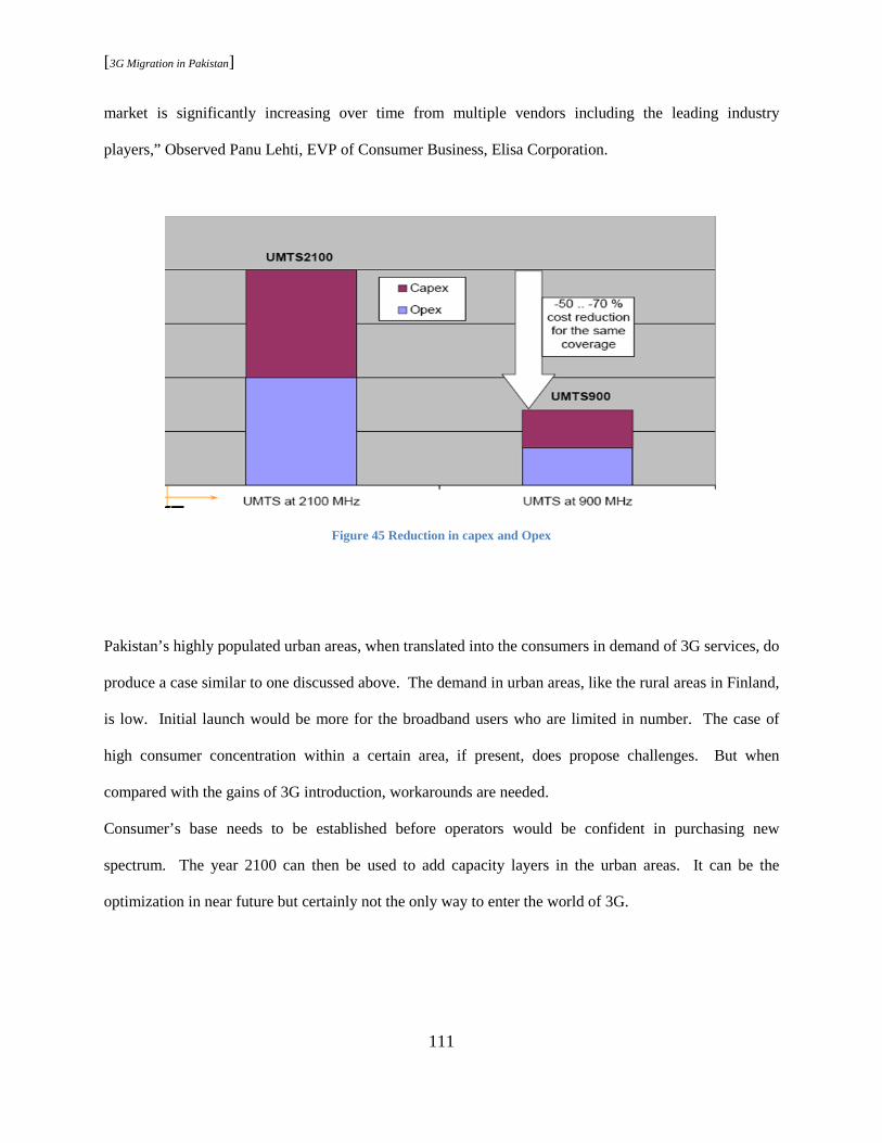
[3G Migration in Pakistan]
111
market is significantly increasing over time from multiple vendors including the leading industry
players,” Observed Panu Lehti, EVP of Consumer Business, Elisa Corporation.
Figure 45 Reduction in capex and Opex
Pakistan’s highly populated urban areas, when translated into the consumers in demand of 3G services, do
produce a case similar to one discussed above. The demand in urban areas, like the rural areas in Finland,
is low. Initial launch would be more for the broadband users who are limited in number. The case of
high consumer concentration within a certain area, if present, does propose challenges. But when
compared with the gains of 3G introduction, workarounds are needed.
Consumer’s base needs to be established before operators would be confident in purchasing new
spectrum. The year 2100 can then be used to add capacity layers in the urban areas. It can be the
optimization in near future but certainly not the only way to enter the world of 3G.
[3G Migration in Pakistan]
112
UMTS900 Operator Case - Optus, Australia
Optus launched its UMTS900 in May 2008. Together with 2100 MHz, the Optus 3G/HSPA network now
reaches over 90% of the population, covering over 500,000 sq km landmass. Majority of coverage is
using 900 MHz. More than 730 UMTS900 sites are now active; over 60 more will come online by
Christmas 2008, taking landmass coverage to over 650,000 sq km, 90% of which will be using
UMTS900. In addition, it has excellent voice services compared to the GSM network. The benefits of
building penetration compared to UMTS2100 are also notable. 900MHz offers better absorption into the
wall and hence lower building penetration loss (BPL).
“Our focus on site optimization during re-farming actually gave our customers a kick up in performance
for their 2G service as well as access to UMTS900. UMTS900 has been critical in bringing up that depth
of coverage into people’s homes, so they get a similar experience in both voice and data coverage,
making it a more economically feasible solution for expansion. By having a technology that allows us to
get into more places at a lower cost, we can deliver more services,” notes Andrew Smith, Director,
Mobile Core Engineering; Optus.
Optus strategy to increase coverage over a wider area with UMTS provides means to expand 3G in the
future in Pakistan too. Once 2100 MHz becomes a reality, the existing site in the urban area may be used
if needed. Or new sites can be added to the far off places. In either case, the result would be expanded
broadband services into the remote and untouched places, providing means to enable the social and
economic revolution as discussed in chapter four.
Options to refarm 900 MHz for UMTS900 - while maintaining the GSM quality

[3G Migration in Pakistan]
113
Option 1: There are enough channels to be taken out for UMTS900 in the rural areas where GSM is
planned based on coverage, i.e. the maximum number of TRX per sector is two.
Option 2: Via GSM investments, enough channels can be allocated to deploy UMTS900 typically in
suburban areas and traffic routes.
Option 3: Via migrating traffic to UMTS2100, enough channels can be allocated to deploy UMTS900 in
small cities and suburban areas and high traffic routes.
Option 4: Deployment of UMTS900 is not yet possible in downtown or other densely populated urban
areas.150
UMTS900 Commercialization
“130 devices announced by 23 suppliers, as of may 2009. So far 10 UMTS900 networks have been
launched. In addition, the 900/2100MHz combination for WCDMA-HSPA is expected to become much
more Commonplace.”151
PTA Approvals
The means to make UMTS900 a possibility again start by the regulation industry. The following is the
global standing today:
150
UMTS900 Market Overview Alan Hadden, President Global mobile Suppliers Association
151
www.gsacom.com/gsm_3g/wcdma_databank.php4

[3G Migration in Pakistan]
114
Figure 46 UMTS900 Global Status
7.7 Concluding Remarks
“The combination of GSM/EDGE and WCDMA under a seamlessly integrated UMTS multi-radio
network should yield the best possible radio performance both for speech and data services.” Provided
multiple bands availability, GSM/EDGE can play an efficient technology in the already deployed cellular
network bands (800, 900, 1800 and 1900) and WCDMA in the new 2100 band (IMT-2000) or other
coming bands over 2 GHz (as it is likely the case in the US). For operators licensed with multiple bands a
joint operation of GSM/EDGE and WCDMA could be the optimum scenario with a UMTS multi-radio
deployment.”152 Due to the present regulatory and market conditions, UMTS900 comes into the picture as
3G enabler prior to the purchase of new spectrum. Its role becomes significant as the region suffers from
delays in regulation and limited consumer demand. The UMTS specifications include support for a hard
handover from UMTS to GSM and vice versa. This is an important requirement, since the widespread
152
http://library.books24x7.com.ezproxy.rit.edu/book/id_4860/viewer.asp?bookid=4860&chunkid=956045739

[3G Migration in Pakistan]
115
rollout of UMTS coverage will take time to complete, and if holes exist in UMTS coverage, it is desirable
that a UMTS subscriber should receive service from the more ubiquitous GSM coverage. Last but not
least, LTE bears high potential in becoming region’s future based on the market, operator, and regulator
response.
The major delays in 3G reality in Pakistan are more towards the regulating end than towards the technical
or market side. Hence, it is not a surprise that the proposed ideas can become reality by efforts beginning
at the same end. PTA’s parallel efforts, enabling 3G within the same spectrum and in new spectrum, are
needed in order to set ground work for a 3G-supporting industry prior to the long awaited spectrum
allocation. The auction itself needs to be innovative to encourage cost and infrastructure sharing among
big players in order to cope with the tremendous fees associated with it. The job of PTA doesn’t end
there, as discussed in article 5.1; the enabling of the business environment is the biggest challenge of the
regulatory bodies.
Consumer market is the ultimate merit of success or failure for 3G in Pakistan. The trends observed in
the next few years would define regions’ response to it. The challenges in this regard are bigger than
technology or regulation. The region bears high potential for applications that could bring high revenues
for the investors and social and economic revolution for the public. The challenge is not only the access
of 3G to masses but also the availability of relative applications and devices. The existing infrastructure
does possess deep roots that, when supported by the regulation, technology, and operators, can make this
task easier. 3G is more than Internet or notebook; it is a revolutionary step towards the world of wireless
broadband. It opens doors to possibilities that can be translated into as many tools, services, and
applications as the region needs.

[3G Migration in Pakistan]
116
Innovation and progress is indeed a catalyst that triggers change, and change in this case may be an
upgrade, evolution, or revolution in technology. The question, which technology and where or how, is
still unanswered. This paper presented a possible journey that the region could embark upon and the
challenges lying ahead as the journey begins!

[3G Migration in Pakistan]
117
Bibliography
Asif, Saad Z. Wireless communications : evolution to 3G and beyond. Boston: Artech House, c2007.
Bannister, Jeffrey. Convergence technologies for 3G networks . Chichester: Wiley, c2004.
Fulle, Professor Ronald. "Telecom Policy."
Garg, Vijay Kumar, 1938-. Wireless network evolution : 2G to 3G. Upper Saddle River, NJ : c2002.
Karim, M. R., 1939-. W-CDMA and cdma2000 for 3G mobile networks . New York: McGraw-Hill, c2002.
Project Management. 2008.
Smith, Clint, P.E. 3G wireless networks. New York : McGraw-Hill, c2007.
Sumit, Kasera and Nishit Narang. 3G Mobile Networks- Architecture, Protocol, and Procedures. NewYork: McGraw-Hill, 2005.
Wang, Jiangzhou, and Tung-Sang Ng. Advances in 3G enhanced technologies for wireless communications. Boston: Artech House, c2002.
[3G Migration in Pakistan]
118
References
White Papers
1. Mobile Streams. “YES 2 3G” - White Paper. February 2001. www.mobile3G.com
2. NMS Communications. 3G Tutorial. Brough Turner and Marc Orange. Originally presented at Fall VON 2002
3. TD-SCDMA – China’s chance
4. Defining 4G: Understanding the ITU Process for the Next Generation of Wireless Technology 3G Americas June 2007
5. Defining 4G: Understanding the ITU Process for the Next Generation of Wireless Technology 3G Americas Revised August 2008
6. HSPA: High Speed Wireless Broadband From HSDPA to HSUPA and Beyond
7. 3GPP Long Term Evolution Retrieved from http://en.wikipedia.org/wiki/3GPP_Long_Term_Evolution"
8. 3G Business Prospects – Analysis of Western European UMTS Markets Jarmo Harno Nokia Research Center Helsinki, Finland
9. Global mobile Suppliers Association. Information Paper. GSM/3G MARKET/TECHNOLOGY UPDATE. July 17, 2009
10. Global mobile Suppliers Association. Information Paper. GSM/3G MARKET/TECHNOLOGY UPDATE. July 10, 2009
11. Global mobile Suppliers Association. Evolution of Network Speeds. GSM/3G MARKET/TECHNOLOGY UPDATE. May 2009
12. Global mobile Suppliers Association. Information Paper. GSM/3G MARKET/TECHNOLOGY UPDATE. April 15, 2009
13. Global mobile Suppliers Association. Information Paper. GSM/3G MARKET/TECHNOLOGY UPDATE. January 30, 2008
14. Global mobile Suppliers Association. Information Paper. GSM/3G MARKET/TECHNOLOGY UPDATE. July 2007
15. Global mobile Suppliers Association. Eastern Europe. GSM/3G MARKET/TECHNOLOGY UPDATE. December 2007
16. Global mobile Suppliers Association. Mobile Universal Access. GSM/3G MARKET/TECHNOLOGY UPDATE. December 1, 2006
17. 3G Long Term Evolution. Aricent White Paper Long Term Evolution (LTE): Overview of LTE Air-Interface Technical White Paper
18. Technical Overview of 3GPP LTE May_18,_2008 Hyung_G._Myung_
19. A White Paper from the UMTS Forum Mobile Broadband Evolution: the roadmap from HSPA to LTE February 2009
20. Rohde and Schwarz. UMTS Long Term Evolution (LTE) Technology Introduction
21. Long-Term Broadband Evolution – Forecasts and Impact of New Technologies K J E L L S T O R D A H L
22. ETSI. From hype to reality Alan Hadden Lemesos, Cyprus 15 – 16 March 2007
23. Distributed Computing Group MOBILE COMPUTING R. Wattenhofer
24. Overview of the Conditions that drive Universal Access Alan Hadden President, GSA Global mobile Suppliers Association
25. ELECTRONIC COMMUNICATIONS COMMITTEE ECC Decision of 18 March 2005 on harmonised utilisation of spectrum for IMT-
2000/UMTS systems operating within the band 2500 – 2690 MHz
26. GSA REPORT TO 3GPP PCG #22 Kyoto April 27, 2009
27. Cisco Mobile Exchange (CMX) Solution Guide. Chapter 2 Overview of GSM, GPRS, and UMTS.
28. Ojanpera, T. and Gray, S.D. “An Overview of cdma2000, WCDMA, and EDGE”
29. Mobile Communications Handbook Ed. Suthan S. Suthersan Boca Raton: CRC Press LLC, 1999
30. 3G AMERICAS UMTS EVOLUTION FROM 3GPP RELEASE 7 TO REALEASE 8 HSPA AND SAI/LTE JUNE 2008
31. 3G Americas The Evolution of UMTS/HSDPA 3GPP Release 6 and Beyond December 2005
32. Wireless Tutorial Brough Turner NMS Communications October 9, 2008
33. The Future of UMTS A services perspective Steve Hearnde UMTS Forum
34. WRC-07 Outcome and some views... Håkan Ohlsén and Lasse Wieweg Ericsson Group Function
35. GERAN Evolution for Increased Speech Capacity Andr´e N. Barreto, Luis G. U. Garcia and Edgar Souza
36. EGPRS2 Uplink Performance for GERAN Evolution Mikko S¨aily, Jari Hulkkonen, and Eduardo Zacar´ıa
37. Evolution of GSM in to the Next Generation Wireless World Prabhakar Chitrapu1, Member, IEEE and Behrouz Aghili
38. 3G Americas THE CASE FOR EVOLVED EDGE AUGUST 2008
39. 3G Americas Evolved EDGE Update (EDGE II) April 2007
40. Capabilities and Impacts of EDGE Evolution toward Seamless Wireless Networks D. Mužić, D.Opatić Mobile Networks Ericsson Nikola
Tesla d.d.
41. Paving the Path for High Data Rates by GERAN Evolution EDGE2 with Dual-Carrier K. Ivanov, C. F. Ball, R. Mullner and H. Winkler
42. Evolution to IMT-SC (EDGE)
43. EDGE Overview and update on EDGE Evolution Alan Hadden, President, GSA Global mobile Suppliers Association Barcelona, October
19, 2005
44. GSM/EDGE Radio Access Network (GERAN) – Evolution of GSM/EDGE towards 3G Mobile Services Shkumbin Hamiti, Eero Nikula,
Janne Parantainen, Timo Rantalainen, Benoist Sébire, Guillaume Sébire. Nokia Research Center
45. UMTS900 – A Case Study Optus June 2009
46. UMTS900 Market Overview Alan Hadden, President Global mobile Suppliers Association UMTS900 Workshop, Cape Town
AfricaCom: November 20, 2008
47. UMTS900 Market Overview Alan Hadden, President Global mobile Suppliers Association UMTS900 Workshop, Dubai GSM>3G
Middle East: December 17, 2008
48. 3G Handsets and Devices Alan Hadden, President Global mobile Suppliers Association (GSA) LTE World Summit Berlin: May 18 – 20,
2009
49. Spectrum for Mobile Broadband – Low Frequency Options Alan Hadden, President Global mobile Suppliers Association (GSA)
50. The Digital Dividend: Ensuring a Legacy of Personal Broadband for All Alan Hadden, President, GSA Global mobile Suppliers
Association

[3G Migration in Pakistan]
119
51. GSMA Digital Dividend Seminar, MWC 2009, Barcelona
52. UMTS900 – A Case Study September 2008 www.gsacom.com
53. UMTS-TDD Retrieved from http://en.wikipedia.org/wiki/UMTS-TDD
54. 3G/UMTS Towards mobile broadband and personal Internet A WHITE PAPER FROM THE UMTS FORUM - OCTOBER 2005
55. QoS implementation in UMTS networks Alcatel Telecommunications Review - 1st Quarter 2001
56. Universal Mobile Telecommunications System Retrieved from
http://en.wikipedia.org/wiki/Universal_Mobile_Telecommunications_System
57. Study of soft handover in UMTS Stijn N. P. Van Cauwenberge COM – Center for Communications, Optics and Materials31 July 2003
58. 3G Policy Update Sheriar Irani
59. Pakistan Telecommunications Report Q1 2008 by BMI
60. Infrastructure Sharing and Shared Operations for Mobile Network Operators From a Deployment and Operations View Dr. Thomas
Frisanco, Member, IEEE Rachel Ang
61. The Evolution of Rel-7 to Rel-8—HSPA and SAE/LTE by 3G Americas
62. The Global Evolution of UMTS/HSDPA - 3GPP Release 6 and Beyond 3G Americas dec 2005
Books
1. Advances in 3G enhanced technologies for wireless communications
2. Wireless communications : evolution to 3G and beyond
3. Wireless network evolution : 2G to 3G
4. 3G wireless networks
5. Convergence technologies for 3G networks [electronic resource] : IP, UMTS, EGPRS and ATM
6. W-CDMA and cdma2000 for 3G Mobile Networks: by M.R. Karim and Mohsen Sarraf
7. 3G mobile networks: architecture, protocols, and procedures
8. QoS in integrated 3G networks.
9. Project management
Internet links
1. 1 http://74.125.95.132/search?q=cache:s3_NvXfdpMIJ:www.it.lut.fi/kurssit/03-04/010990000/gsm- 2. 1 http://www.astricon.net/topics/broadband-mobile/articles/20436-nortel-announces-new-evolved-edge-communication-
technology.htm 3. 1 http://www.benoa.net/publications/ict2001.pdf 4. 1 http://www.itu.int/ITU-D/imt-2000/DocumentsIMT2000/What_really_3G.pdf 5. 1 http://www.radio-electronics.com/info/cellulartelecomms/umts/umts_wcdma_radio.php 6. 1 http://www.umtsworld.com/technology/handover.htm 7. 1 http://www.webbuyersguide.com/resource/white-paper/9246/UMTS-Evolution-from-3GPP-Release-7-to-Release-8-HSPA-and-
SAE-LTE 8. 1 http://www1.alcatel-lucent.com/doctypes/articlepaperlibrary/pdf/ATR2001Q1/gb/09baudetgb.pdf 9. 1 http://www1.alcatel-lucent.com/doctypes/articlepaperlibrary/pdf/ATR2001Q1/gb/09baudetgb.pdf 10. 1 www.umts-forum.org/component/option,com.../task.../Itemid,12/ 11. 1 YES 2 3G” - White Paper www.mobilestream.com 12. http://oldwww.com.dtu.dk/research/networks/OPNET/UMTS_handover.pdf 13. http://www.3gamericas.org/index.cfm?fuseaction=page§ionid=245 14. http://www.itu.int/ITU-D/imt-2000/DocumentsIMT2000/Spectrum-IMT.pdf 15. http://www.mobilecomms-technology.com/projects/hsupa/ 16. http://www.umtsworld.com/technology/handover.htm 17. Source-ITU http://www.itu.int/osg/spu/ni/3G/technology/ 18. www.itu.int/osg/spu/imt-2000/technology.html 19. www.nmscommunications.com
[3G Migration in Pakistan]
120
Glossary
Acronym List
1xEV-DO 1x Evolution-Data Optimized or Evolution-Data Only 3GPP Third Generation Partnership Project AA Adaptive Array AAA Authentication, Authorization and Accounting ACK/NAK Acknowledgement/Negative Acknowledgement ADSL Asynchronous Digital Subscriber Line AGPS Assisted Global Positioning System AMBR Aggregate Maximum Bit Rate AMC Adaptive Modulation and Coding AMR Adaptive Multi-Rate ARPU Average Revenue Per User ASME Access Security Management Entity ATM Automated Teller Machine BCH Broadcast Channel BTS Base Transceiver Station C/I Carrier to Interference Ratio (CIR) CAGR Compound Annual Growth Rate CAZAC Constant Amplitude Zero Autocorrelation Waveform CCE Control Channel Elements CCPCH Common Control Physical Channel CDM Code Division Multiplexing CDMA Code Division Multiple Access CK/IK Ciphering Key/Integrity Key CN Control Network CN Core Network CPC Continuous Packet Connectivity CQI Channel Quality Indications CS Circuit Switched CSCF Call Session Control Function CSI Combination of Circuit Switched and Packet Switched services CTIA Cellular Telecommunication Industry Association DBCH Dynamic BCH DCH Dedicated Channel DFT Discrete Fourier Transformation DIP Dominant Interferer Proportion DL Downlink DL-SCH Downlink Shared Channel DMB Digital Multimedia Broadcasting DPCCH Dedicated Physical Control Channel DRX Discontinuous Reception DSCH Dedicated Shared Channel DSL Digital Subscriber Line DSL Digital Subscriber Line DS-MIPv6 Dual Stack – Mobile Internet Protocol version 6 DTX Discontinuous Transmission D-TxAA Double Transmit Adaptive Array E2E End to End E-MBMS Enhanced Multi Broadcast Multicast Service eNodeB Evolved Node B EPC Evolved Packet Core; also known as SAE (refers to flatter-IP core network) EPDG Evolved Packet Data Gateway EPRE Energy Per Resource Element EPS Evolved Packet System is the combination of the EPC/SAE (refers to flatter-IP core network) and ETSI European Telecommunication Standards Institute ETSI-SCP ETSI – Standard Commands for Programming E-UTRAN Evolved Universal Terrestrial Radio Access Network EUTRAN Evolved Universal Terrestrial Radio Access Network (based on OFDMA) EV-DO Evolution, Data Optimised FBC Flow Based Charging FBI Fixed Broadband access to IMS FDD Frequency Division Duplex FDM Frequency Division Multiplex
[3G Migration in Pakistan]
121
FDS Frequency Diverse Scheduling FFR Fractional Frequency Re-use flatter-IP core network) FMC Fixed Mobile Convergence FOMA Freedom of Mobile Multimedia Access: brand name for the 3G services offered by Japanese FSS Frequency Selected Scheduling FTTH Fibre to the Home GB Gigabyte GBR Guaranteed Bit Rate GERAN GSM EDGE Radio Access Network Gn IP Based interface between SGSN and other SGSNs and (internal) GGSNs. DNS also shares this GPON Gigabit Passive Optical Network GPRS General Packet Radio System GRUU Globally Routable User Agent URIs GSM Global System for Mobile communications GSMA GSM Association GTP GPRS Tunneling Protocol GUP Generic User Profile GW Gateway HARQ Hybrid Automatic Response reQuest HD High Definition HLR Home Location Register HOM Higher Order Modulation HPCRF Home PCRF HPLMN Home PLMN HSDPA High Speed Downlink Packet Access HS-DSCH High Speed Downlink Shared Channel HSPA + High Speed Packet Access Plus (also known as HSPA Evolution) HSPA High Speed Packet Access (HSDPA + HSUPA) HSPA+ HSPA Evolution HS-PDSCH High Speed- Physical Downlink Shared Channel HSS Home Subscriber Server HS-SCCH High-Speed Shared Control Channel HSUPA High Speed Uplink Packet Access ICS IMS Centralized Services IDs identifies IETF Internet Engineering Task Force (www.ietf.org) IMSI International Mobile Subscriber Identity IMT International Mobile Telecommunications IN Intelligent Networking interface. Uses the GTP Protocol. IP TV Internet Protocol Television ISIM IMS SIM ISP Internet Service Provider ITU International Telecommunication Union J2ME Java 2 Micro Edition kHz Kilohertz LCS LoCation Service LMMSE Least Minimum Mean Squared Error LSTI LTE SAE Trial Initiative LTE Long Term Evolution LTE Long Term Evolution (Evolved Air Interface based on OFDMA) M2M Machine to Machine MAC Media Access Control MAC=Medium Access Control, part of layer 2 in the OSI model MBMS Multimedia Broadcast/Multicast Service MBR Maximum Bit Rate MCS Modulation and Coding Scheme MFS Mobile Financial Services MHz Megahertz MIMO Multiple-Input Multiple-Output MIP Mobile IP MITE IMS Multimedia Telephony Communication Enabler MMS Multimedia Messaging Service MMSE Multimedia Messaging Service Environment mobile phone operator NTT DoCoMo. MPLS Multi-Protocol Label Switching MRFP Multimedia Resource Function Processor MSA Metropolitan Statistical Area

[3G Migration in Pakistan]
122
MU-MIMO Multi-User Multiple Input Multiple Output NAI Network Access Identifier NFC Near Field Communications NGMN Next Generation Mobile Networks NGN Next Generation Network NGN Next Generation Network OFDMA Orthogonal Frequency Division Multiplexing Access (air interface) OMA Open Mobile Architecture OP Organizational Partner OPEX Operating Expenses OTA Over The Air OVSF Orthogonal Channel Noise Simulator P2P Peer-to-Peer PAR Peak to Average Ratio PARC Per-Antenna Rate Control PBCH Primary BCH PC Personal Computer PCC Policy and Charging Convergence PCMCIA Personal Computer Manufacturers’ Card Interface Adapter PCRF Policy and Changing Rules Function PCS Personal Communication System PDA Personal Digital Assistant PDSCH Physical Downlink Shared Channel PHY/MAC PHY: common abbreviation for the physical layer of the OSI model. PLMN Public Land Mobile Network PMIP Proxy Mobile IPv6 PoC Push-to-talk over Cellular PoS Point of Sale POTS Plain Old Telephone Service PRACH Physical Random Access Channel PS Packet Switched P-SCH Primary Synchronization Signal PSI Public Service Identities PSTN Public Switched Telephone Network QAM Quadrature Amplitude Modulation QAM Quadrature Amplitude Modulation QPSK Quadrature Phase Shift Keying RAB Radio Access Bearer RACH Random Access Channel RAN Radio Access Network RAT Radio Access Technology RB Radio Bearer RE Resource Elements REL-X Release ‘99, Release 4, Release 5, etc. from 3GPP standardization RIT Radio Interface Technology RNC Radio Network Controller RRC Radio Resource Control SAE System Architecture Evolution also known as Evolved Packet System (EPS) Architecture (refers to SBLB Service Based Local Policy SC-FDMA Single Carrier – Frequency Division Multiple Access SD Standard Definition SDMA Spatial Division Multiple Access SF-16 Spreading Factor 16 SFBA Switch Fixed Beam Array SFBC Space Frequency Block Code SFN Single Frequency Network SGSN Serving GPRS Support Node SGSN Serving GPRS Support Node SIM Subscriber Identity Module SIMO Single Input Multiple Output SIR Signal-to-Interference Ratio SISO Single Input Single Output SMS Short Message Service SNR Signal-to-Noise Ratio SON Self-Organising Network SRNC Serving Radio Network Controller S-SCH Secondary Synchronization Code STTD Space-Time Transmit Diversity SU-MIMO Single-User Multiple Input Multiple Output
[3G Migration in Pakistan]
123
TCP/IP Transmission Control Protocol/Internet Protocol TDD Time Division Duplex TDD Time Division Duplex TDS Time Domain Scheduling TF Transport Format TFC Transport Format Combination the LTE/EUTRAN TPC Transmit Power Control TTI Transmission Time Interval UE User Equipment UGC User Generated Content UICC User Interface Control Channel UL Uplink UL-SCH Uplink Shared Channel UMTS Universal Mobile Telecommunication System UPE User Plane Entity URI Universal Resource Identifier USB Universal Serial Bus USIM UMTS SIM UTRA Universal Terrestrial Radio Access UTRAN UMTS Terrestrial Radio Access Network UTRAN Universal Terrestrial Radio Access Network VoD Video on Demand VoIP Voice over Internet Protocol VoIP Voice over IP VPCRF Visiting PCRF VPLMN Visiting PLMN VPN Virtual Private Network WAP Wireless Application Protocol WCDMA Wideband Code Division Multiple Access WiMAX Worldwide Interoperability for Microwave Access WLAN Wireless Local Area Network WLAN Wireless Local Area Network WRC’07 World Radiocommunication Conference 2007 xHTML-MP xHyper-Text Markup Language - Mobile Phone
Abbreviations
3GPP 3rd Generation Partnership Project ACK Acknowledgement ACLR Adjacent Channel Leakage Ratio ARQ Automatic Repeat Request AS Access Stratum BCCH Broadcast Control Channel BCH Broadcast Channel CAPEX Capital Expenditures CAZAC Constant Amplitude Zero Auto-Correlation CCDF Complementary Cumulative Density Function CCPCH Common Control Physical Channel CP Cyclic Prefix C-plane Control Plane CQI Channel Quality Indicator CRC Cyclic Redundancy Check DCCH Dedicated Control Channel DFT Discrete Fourier Transform DL Downlink DL-SCH Downlink Shared Channel DRX Discontinuous Reception DTCH Dedicated Traffic Channel DTX Discontinuous Transmission DVB Digital Video Broadcast eNB E-UTRAN NodeB

[3G Migration in Pakistan]
124
EPC Evolved Packet Core E-UTRA Evolved UMTS Terrestrial Radio Access E-UTRAN Evolved UMTS Terrestrial Radio Access Network FDD Frequency Division Duplex FFT Fast Fourier Transform GERAN GSM EDGE Radio Access Network GSM Global System for Mobile communication HARQ Hybrid Automatic Repeat Request HSDPA High Speed Downlink Packet Access HSUPA High Speed Uplink Packet Access IFFT Inverse Fast Fourier Transformation IP Internet Protocol LTE Long Term Evolution MAC Medium Access Control MU-MIMO Multi User MIMO NACK Negative Acknowledgement NAS Non Access Stratum OFDM Orthogonal Frequency Division Multiplexing OFDMA Orthogonal Frequency Division Multiple Access OPEX Operational Expenditures PAPR Peak to Average Power Ratio PAPR Peak-to-Average Power Ratio PCCH Paging Control Channel QAM Quadrature Amplitude Modulation QoS Quality of Service QPSK Quadrature Phase Shift Keying RACH Random Access Channel RAN Radio Access Network RAT Radio Access Technology RB Radio Bearer RF Radio Frequency RLC Radio Link Control RRC Radio Resource Control S1 Interface between eNB and aGW S1-C S1-Control plane S1-U S1-User plane SAE System Architecture Evolution SC-FDMA Single Carrier – Frequency Division Multiple Access SCH Synchronization Channel SU-MIMO Single User MIMO TDD Time Division Duplex TS Technical Specification TTI Transmission Time Interval UE User Equipment UL Uplink UL-SCH Uplink Shared Channel UMTS Universal Mobile Telecommunications System UPE User Plane Entity U-plane User plane UTRA UMTS Terrestrial Radio Access UTRAN UMTS Terrestrial Radio Access Network VoIP Voice over IP WCDMA Wideband Code Division Multiple Access WLAN Wireless Local Area Network X2 Interface between eNBs X2-C X2-Control plane X2-U X2-User plane