3D seismic geomorphology and sedimentology of … of the Geological Society, London, Vol. 168, 2011,...
14
Journal of the Geological Society , London, Vol. 168, 2011, pp. 393–405. doi: 10.1144/0016-76492010-047. 393 3D seismic geomorphology and sedimentology of the Chalk Group, southern Danish North Sea STEFAN BACK 1 *, HEIJN VAN GENT 2 , LARS REUNING 1 , JU ¨ RGEN GRO ¨ TSCH 3 , JAN NIEDERAU 1 & PETER KUKLA 1 1 Geological Institute, RWTH Aachen University, 52062 Aachen, Germany 2 Structural Geology–Tectonics–Geomechanics, RWTH Aachen University, 52056 Aachen, Germany 3 Shell EP Europe, NAM, 9400 HH Assen, The Netherlands *Corresponding author (e-mail: [email protected]) Abstract: Classically, the North Sea Chalk is interpreted as having been deposited under quiet, homogeneous pelagic conditions with local redeposition in slumps and slides. Recent observations of highly discontinuous reflection patterns on 2D and 3D seismic reflection data from the NW European Chalk Group have led to a revision of some general ideas of chalk deposition, with the suggestion that long-lived, contour-parallel bottom currents exerted a primary influence on the development of intra-chalk channels, drifts and mounds. This study proposes an alternative explanation for the formation of selected intra-chalk seismic and stratal discontinuities, interpreting these as being caused by gravity-driven processes that developed in response to intense syndepositional tectonics. Submarine mass-transport systems identified in the study area include large- scale slumps, slides, debris flows and turbidites. The last occur in sinuous channel systems flanked by large master levees, with the channel fill exhibiting well-developed secondary banks and overbanks on the outer bends of the channel thalweg. This first documentation of channelized density-flow deposits in the North Sea Chalk has important consequences for the interpretation and prediction of redeposited chalk units, emphasizing at the same time the strength of detailed 3D seismic discontinuity detection for subsurface sedimentary-systems analysis. The Upper Cretaceous to Lower Palaeogene Chalk Group of NW Europe is a biogenic deposit mainly of pelagic origin (e.g. Hancock 1975; Kennedy 1987; Surlyk 1997; Surlyk et al. 2003, 2008; Van der Molen et al. 2005; Esmerode et al. 2008). Its deposition is classically assumed to represent the settlement of calcarous ooze from suspension, draping pre-existing submarine morphology by a monotonous ‘blanket deposit’ with mainly parallel bedding relationships and high lateral continuity (for a critical discussion see, e.g. Evans et al. 2003; Surlyk et al. 2008). However, redeposited, less homogeneous chalk sediments have also been identified in the past, mainly in and adjacent to tectonically active areas (e.g. Hardman 1982; Brewster & Dangerfield 1984; Hatton 1986; Bromley & Ekdale 1987; Cart- wright 1989; Clausen & Huuse 1999; Skirius et al. 1999; Evans et al. 2003; Lykke-Andersen & Surlyk 2004; Van der Molen et al. 2005). Recently, the documentation of significant intra-chalk erosional surfaces, channels, slump scarps and mass-transport complexes on 2D and 3D seismic reflection datasets both onshore (Evans et al. 2003) and offshore NW Europe (e.g. Lykke-Andersen & Surlyk 2004; Van der Molen et al. 2005; Esmerode et al. 2007, 2008; Surlyk & Lykke-Andersen 2007; Surlyk et al. 2008) initiated a revision of the general ideas of chalk deposition, with the most recent publications arguing that powerful, long-lived, contour-parallel bottom currents acted as the primary control for the development of intra-chalk channels, drifts and mounds. This paper provides an alternative explanation for the formation of many of the significant intra-chalk seismic and stratal discontinuities by interpreting these as being caused by gravity-driven erosional and sedimentary processes that devel- oped in response to intense syndepositional tectonics. The 3D seismic reflection survey analysed in this study covers c. 2000 km 2 of the Danish North Sea Central Graben, bound by the Ringkøbing–Fyn High in the east, extending in its central part across the Bo-Jens, Gorm-Lola, Tyra-Igor, Igor-Emma and Adda Ridges, and reaching in the south the Danish Salt Dome province (Fig. 1). The seismic reflection character of the Chalk Group ranges from continuous to highly discontinuous. In the case of pronounced seismic discontinuity, reflections exhibit numerous truncations that result in isolated and oblique reflec- tions with respect to the surrounding reflection packages, and frequent lateral changes in reflection polarity indicating that depositional units of differing impedance are juxtaposed against each other. To gain a basinwide overview of the 3D distribution of seismic discontinuity features throughout the Chalk Group, a fast-track 3D horizon framework was constructed comprising three iso-proportional surfaces between the Top- and Base-Chalk marker horizons (Fig. 2; Top- and Base-Chalk interpretations provided by Maersk Olie og Gas and DUC partners). This subdivision defined three coarse interpretation levels, a basal Chalk I level (Base-Chalk reflection to Iso-Surface 1), a central Chalk II level (between Iso-Surfaces 2 and 3) and a topmost Chalk III level (Iso-Surface 3 to Top-Chalk reflection; the prime target interval for hydrocarbon exploration). In large parts of the study area, the iso-proportional surfaces honour the general trend of the subsurface stratigraphy; however, there are clearly regions where they cut across seismic reflections, particularly in areas characterized by pronounced stratal inhomogeneity (Fig. 2). However, the use of such phantom horizons allows the reconnais- sance analysis of extensive areas of highly discontinuous seismic stratigraphy, whereas a reflection-based interpretation will result in a 3D patchwork of countless, small horizon fragments that prevents a broad, survey-wide seismic visualization. Hence, the
Transcript of 3D seismic geomorphology and sedimentology of … of the Geological Society, London, Vol. 168, 2011,...

Journal of the Geological Society, London, Vol. 168, 2011, pp. 393–405. doi: 10.1144/0016-76492010-047.
393
3D seismic geomorphology and sedimentology of the Chalk Group, southern
Danish North Sea
STEFAN BACK 1*, HEIJN VAN GENT 2, LARS REUNING 1, J URGEN GROTSCH 3, JAN NIEDERAU 1
& PETER KUKLA 1
1Geological Institute, RWTH Aachen University, 52062 Aachen, Germany2Structural Geology–Tectonics–Geomechanics, RWTH Aachen University, 52056 Aachen, Germany
3Shell EP Europe, NAM, 9400 HH Assen, The Netherlands
*Corresponding author (e-mail: [email protected])
Abstract: Classically, the North Sea Chalk is interpreted as having been deposited under quiet, homogeneous
pelagic conditions with local redeposition in slumps and slides. Recent observations of highly discontinuous
reflection patterns on 2D and 3D seismic reflection data from the NW European Chalk Group have led to a
revision of some general ideas of chalk deposition, with the suggestion that long-lived, contour-parallel bottom
currents exerted a primary influence on the development of intra-chalk channels, drifts and mounds. This
study proposes an alternative explanation for the formation of selected intra-chalk seismic and stratal
discontinuities, interpreting these as being caused by gravity-driven processes that developed in response to
intense syndepositional tectonics. Submarine mass-transport systems identified in the study area include large-
scale slumps, slides, debris flows and turbidites. The last occur in sinuous channel systems flanked by large
master levees, with the channel fill exhibiting well-developed secondary banks and overbanks on the outer
bends of the channel thalweg. This first documentation of channelized density-flow deposits in the North Sea
Chalk has important consequences for the interpretation and prediction of redeposited chalk units,
emphasizing at the same time the strength of detailed 3D seismic discontinuity detection for subsurface
sedimentary-systems analysis.
The Upper Cretaceous to Lower Palaeogene Chalk Group of NW
Europe is a biogenic deposit mainly of pelagic origin (e.g.
Hancock 1975; Kennedy 1987; Surlyk 1997; Surlyk et al. 2003,
2008; Van der Molen et al. 2005; Esmerode et al. 2008). Its
deposition is classically assumed to represent the settlement of
calcarous ooze from suspension, draping pre-existing submarine
morphology by a monotonous ‘blanket deposit’ with mainly
parallel bedding relationships and high lateral continuity (for a
critical discussion see, e.g. Evans et al. 2003; Surlyk et al.
2008). However, redeposited, less homogeneous chalk sediments
have also been identified in the past, mainly in and adjacent to
tectonically active areas (e.g. Hardman 1982; Brewster &
Dangerfield 1984; Hatton 1986; Bromley & Ekdale 1987; Cart-
wright 1989; Clausen & Huuse 1999; Skirius et al. 1999; Evans
et al. 2003; Lykke-Andersen & Surlyk 2004; Van der Molen et
al. 2005). Recently, the documentation of significant intra-chalk
erosional surfaces, channels, slump scarps and mass-transport
complexes on 2D and 3D seismic reflection datasets both
onshore (Evans et al. 2003) and offshore NW Europe (e.g.
Lykke-Andersen & Surlyk 2004; Van der Molen et al. 2005;
Esmerode et al. 2007, 2008; Surlyk & Lykke-Andersen 2007;
Surlyk et al. 2008) initiated a revision of the general ideas of
chalk deposition, with the most recent publications arguing that
powerful, long-lived, contour-parallel bottom currents acted as
the primary control for the development of intra-chalk channels,
drifts and mounds. This paper provides an alternative explanation
for the formation of many of the significant intra-chalk seismic
and stratal discontinuities by interpreting these as being caused
by gravity-driven erosional and sedimentary processes that devel-
oped in response to intense syndepositional tectonics.
The 3D seismic reflection survey analysed in this study covers
c. 2000 km2 of the Danish North Sea Central Graben, bound by
the Ringkøbing–Fyn High in the east, extending in its central
part across the Bo-Jens, Gorm-Lola, Tyra-Igor, Igor-Emma and
Adda Ridges, and reaching in the south the Danish Salt Dome
province (Fig. 1). The seismic reflection character of the Chalk
Group ranges from continuous to highly discontinuous. In the
case of pronounced seismic discontinuity, reflections exhibit
numerous truncations that result in isolated and oblique reflec-
tions with respect to the surrounding reflection packages, and
frequent lateral changes in reflection polarity indicating that
depositional units of differing impedance are juxtaposed against
each other. To gain a basinwide overview of the 3D distribution
of seismic discontinuity features throughout the Chalk Group, a
fast-track 3D horizon framework was constructed comprising
three iso-proportional surfaces between the Top- and Base-Chalk
marker horizons (Fig. 2; Top- and Base-Chalk interpretations
provided by Maersk Olie og Gas and DUC partners). This
subdivision defined three coarse interpretation levels, a basal
Chalk I level (Base-Chalk reflection to Iso-Surface 1), a central
Chalk II level (between Iso-Surfaces 2 and 3) and a topmost
Chalk III level (Iso-Surface 3 to Top-Chalk reflection; the prime
target interval for hydrocarbon exploration). In large parts of the
study area, the iso-proportional surfaces honour the general trend
of the subsurface stratigraphy; however, there are clearly regions
where they cut across seismic reflections, particularly in areas
characterized by pronounced stratal inhomogeneity (Fig. 2).
However, the use of such phantom horizons allows the reconnais-
sance analysis of extensive areas of highly discontinuous seismic
stratigraphy, whereas a reflection-based interpretation will result
in a 3D patchwork of countless, small horizon fragments that
prevents a broad, survey-wide seismic visualization. Hence, the
analysis of seismic reflectivity and discontinuity attributes
(chaos, variance) projected onto the iso-proportional surfaces
allowed a first-pass identification of seismically continuous areas
and regions characterized by subsurface reflection discontinuity
caused by features that were subsequently selected for detailed,
reflection-based seismic interpretation and 3D seismic–geomor-
phological analysis.
3D seismic overview based on iso-surface slicing
In the Chalk I interval between the Base-Chalk reflection and
Iso-Surface 1 (Fig. 2), seismic discontinuity data indicate that
most parts of the study area are characterized by coherent,
laterally continuous seismic reflections (Fig. 3a and b). This is
particularly the case at and immediately above the strong
amplitude peak interpreted as the Base-Chalk reflection (Figs 2
and 3c, d). Dissemblant reflection information at Base-Chalk
level mainly concentrates on the Bo-Jens and Igor-Emma Ridges
and the Coffee-Soil Fault Zone (Fig. 3a) where sharp, linear, in
places branching chaos-attribute signatures indicate the subsur-
face presence of faults. Stratal discontinuity is observed in the
northeasternmost of the study area in the hanging wall of the
Coffee-Soil Fault, where slightly mounded reflections with a
lobate termination occur. These features are suggestive of
isolated, small-scale mass-transport complexes (Fig. 3d). In the
southernmost part of the study area, a pair of sharp, parallel-
trending, slightly sinuous to almost linear chaos-attribute features
that extend in a NW–SE direction over a length of c. 10 km
(Fig. 3b and c) indicate the presence of a c. 1 km wide incision
immediately west of the southernmost salt-rim syncline. This
discontinuity feature can be interpreted as a weakly incised low-
sinuosity channel or channel segment (Channel I; Fig. 3b and c).
Another subtle, almost linear reflection irregularity descends over
20 km from the Tyra-Igor Ridge in the central part of the study
area towards the southern Salt Dome province (Fig. 3a and b).
This elongate seismic discontinuity is also characterized by a
Fig. 1. Regional map showing the location of the study area in the North
Sea Central Graben offshore Denmark and the principal tectonic
elements of the Central Graben area (modified after Cartwright 1991;
Vejbæk & Andersen 2002; Japsen et al. 2003; Esmerode et al. 2008).
The location of the 3D seismic dataset analysed in this study is indicated
by the thick black outline. The black horizontal line indicates the position
of the seismic line shown in Figure 2.
Fig. 2. Illustration of the initial, fast-track 3D seismic interpretation approach used in this study. This approach is based on the calculation of three iso-
proportional surfaces (phantom horizons) between the Top-Chalk (negative) and Base-Chalk (positive) marker reflections, subdividing the Chalk Group
into three preliminary interpretation levels, a Chalk I level (Base-Chalk reflection to Iso-Surface 1), a Chalk II level (between Iso-Surfaces 2 and 3) and a
Chalk III level (Isosurface 3 to Top-Chalk reflection). Lateral seismic visualization along and between the iso-surfaces is survey-wide. This approach
allows identification of seismic discontinuity features (Figs 3–5), which can be subsequently mapped in detail with reflection-based seismic interpretation
techniques honouring stratigraphic relationships.
S . BACK ET AL .394

Fig. 3. Chalk I overview interpretation. (a) Chaos-attribute data extracted in Chalk I interval, and (b) survey-wide interpretation. The discontinuity-slice
data show that at Chalk I level vast areas are characterized by highly continuous stratal configuration (white areas; laterally discontinuous seismic
signature shown in black). (c) Close-up view of lateral chaos-attribute extraction in the south of the study area (upper left), synoptic display of lateral
reflectivity distribution (upper right; reflectivity data in ‘European’ zero-phase polarity; positive amplitudes in blue, negative amplitudes in red, which
applies for all lateral and vertical reflectivity displays presented in the following figures), and vertical reflectivity section (bottom) of the slightly sinuous
Channel I (length c. 10 km, width c. 1 km). Yellow crosses on reflectivity image indicate the base of the channel incision. (d) Variance-attribute close-up
(top) and vertical reflectivity display (bottom) of a seismic discontinuity feature observed along the Coffee-Soil Fault in the northeasternmost part of the
study area, where slightly mounded reflections with lobate terminations suggest the occurrence of small-scale mass-transport deposits.
3D SEISMIC GEOMORPHOLOGY IN THE CHALK GROUP 395
low degree of sinuosity, little basal incision, and a thickness of
less than 20 ms (two-way travel time; TWT). The average width
of the discontinuity feature is around 200 m, with local dissem-
blance bulges in its central part up to 500 m wide (Fig. 3a and
b). This feature can also be interpreted as low-sinuosity channel
(Channel II), with the central dissemblance bulges suggestive of
crevasse splays (Fig. 3a and b). The system terminates in a flat-
topped, triangle-shaped lateral amplitude irregularity (additional
positive-to-negative seismic loop) of c. 10 km2 extent in the
southernmost salt-rim syncline of the study area (Fig. 3a and b).
Its shape is indicative of a frontal splay deposit sensu Posamen-
tier & Kolla (2003), with its reflection signature suggesting a
deposit of lower density than the surrounding chalk.
In the Chalk II interval (Iso-Surfaces 1–3; see Fig. 2), large
parts of the survey area are characterized by reflections produ-
cing a highly discontinuous, rather chaotic seismic pattern (Fig.
4). The surface-slice analysis of chaos-attribute discontinuity
data (Fig. 4a) reveals that subparallel, continuous reflection
patterns are generally rare; instead, a multitude of reflection
discontinuities occur, including seismic reflection patterns that
are suggestive of large-scale mass-transport systems (slides and
slumps; Fig. 4b). There are also a variety of linear and curved
dissemblance features resembling channel systems that are
oriented in different directions, including those with trends
mainly southward (Channels III and IV on the eastern flank Bo-
Jens Ridge; Fig. 4b–d), to the east (Channel V on the north-
eastern flank Tyra-Igor Ridge; Fig. 4b), and westward (Channel
VI in the northern part of Salt Dome province; Fig. 4b). The
vertical display of reflectivity data also shows a pronounced
seismic discontinuity in the central Chalk II interval with
numerous reflection terminations at steeply dipping, U- and V-
shaped truncation surfaces interpreted as channel incisions (Fig.
4d). Within these incisions, asymmetric reflection patterns, a
lateral and vertical migration of erosion surfaces, and the
truncation of older incision or infill reflections by younger
erosional features are common, as is the local preservation of
onlapping incision fill suggestive of channel inner banks and
overbank units (Fig. 4d). The sidewalls of the major incision
features are locally influenced by slope instability, as indicated
by the occurrence of small-scale faults (linear chaos-attribute
discontinuities) trending parallel to the channel axis that are
associated with small, arcuate-shaped discontinuities interpreted
as slides or slumps (e.g. western flank of Tyra-Igor Ridge, Fig.
4a and b). On the southwestern and northeastern flanks of the
Tyra-Igor Ridge, more extensive (.150 km2), arcuate zones of
highly discontinuous seismic facies are interpreted to record the
subsurface presence of large-scale mass-transport complexes
(MTC; Fig. 4a and b). Vertical reflectivity sections across these
features show reflection units of significant internal distortion
that descend from the Tyra-Igor Ridge both into southwestern
direction into the Salt Dome province (MTC A; Fig. 4e), and
towards the NE into the Coffee-Soil fault zone (MTC B; Fig. 4f).
The observation of U-shaped erosive features above these
distorted units (Fig. 4e and f) suggests that sliding and slumping
was succeeded by channel incision.
In the Chalk III interval between Iso-surface 3 and the Top-
Chalk reflection (Fig. 2), the survey-wide seismic chaos-attribute
data documents that the reflection pattern is again rather homo-
geneous and of relatively high lateral continuity (Fig. 5a and b),
similar to the Chalk I interval. In contrast to the multitude of
linear discontinuity features observed in the Chalk II interpreta-
tion level below, the presence of a horizontally dendritic to
circular (Fig. 5a and c), vertically mounded seismic discontinuity
facies (Fig. 5d) characterizes this interval, primarily on the Adda
and Igor-Emma Ridges. Outside these areas, minor linear seismic
discontinuity features interpreted as faults characterize the Gorm-
Lola Ridge and the western survey boundary (Fig. 5a and b).
The seismic overview analysis based on the fast-track, iso-
proportional slicing of the Chalk Group interval in the study area
documents that the occurrence of seismic discontinuity facies is
almost as common as seismic reflection continuity, which is in
line with previous studies that identified significant intra-chalk
stratal inhomogeneity (e.g. Evans et al. 2003; Lykke-Andersen &
Surlyk 2004; Van der Molen et al. 2005; Esmerode et al. 2007,
2008; Surlyk & Lykke-Andersen 2007; Surlyk et al. 2008). At the
Chalk II level (Fig. 4), stratal discontinuity seems dominant with
numerous reflection truncations, incisions and the presence of
extensive reflection packages of significant internal distortion,
features that are indicative of considerable erosion, transport and
redeposition of chalk material. To evaluate the validity of the
first-pass interpretations based on iso-proportional seismic
volume slicing, the following paragraphs provide a more detailed,
horizon-based analysis of the morphology and seismic expression
of the most prominent reflection discontinuity features identified
in the study area, focusing on (1) the linear and sinuous incision
features suggestive of channels, (2) the internally distorted
reflection packages suggestive of slide, slump and possibly
debris-flow deposits, and (3) the pronounced seismic discontinuity
facies that characterizes considerable areas at the Chalk III level.
Detailed seismic interpretation and analysis of keystratal discontinuities
Seismic incision features interpreted as channels
Both the north and south of the study area exhibit extensive
zones of seismic reflection truncation by elongate discontinuity
features interpreted as channels. In the northern part of the study
area, the most intensive zone of probable channel incision is
located between the Bo-Jens and Adda Ridges (Fig. 4; also see
Esmerode et al., 2008). With a width of over 10 km in its
proximal part, the main incision pathway can be traced for c.
20 km into a region west of the Gorm-Lola Ridge. In the
southern part of the study area, the main location of reflection
truncation by elongate dissemblance features is located east of
the Gorm-Lola Ridge (Fig. 4). The largest incision features
observed in this part trend in a westerly direction on the
southwestern flank of Tyra-Igor Ridge, turning southward where
entering the salt-rim syncline east of the Gorm-Lola Ridge.
Figure 6 illustrates the results of a detailed, reflection-based
interpretation of the proximal regions of one main U-shaped
incision between the Bo-Jens, Tyra-Igor and Adda Ridges inter-
preted as Channel IV (also see Fig. 4b–d). Reflection picks that
define the outline of the studied system were placed at the
negative-to-positive zero-crossing at the incision base and flanks,
coinciding in many places with prominent terminations of the
surrounding reflections (see Fig. 6, vertical reflectivity data).
Within the incision, lap surfaces and reflection truncations were
mapped to highlight infill variations along its course. Channel IV
has an average width of 2.5 km, with an erosional base cutting
along a sinuous downslope trend several tens of ms TWT into the
underlying substratum. Gull-wing shaped reflections at the outer
edges of the incision are interpreted as master levees that flank the
channel in its northern, proximal part on both sides (Fig. 6,
sections A–A’ to C–C’). These features are less clear in the south
(Fig. 6, sections D–D’ and E–E’) where a tributary channel
(Channel III, see Fig. 4c and d) enters Channel IV. Within the
incision, various small-scale reflection packages either onlap the
S. BACK ET AL .396
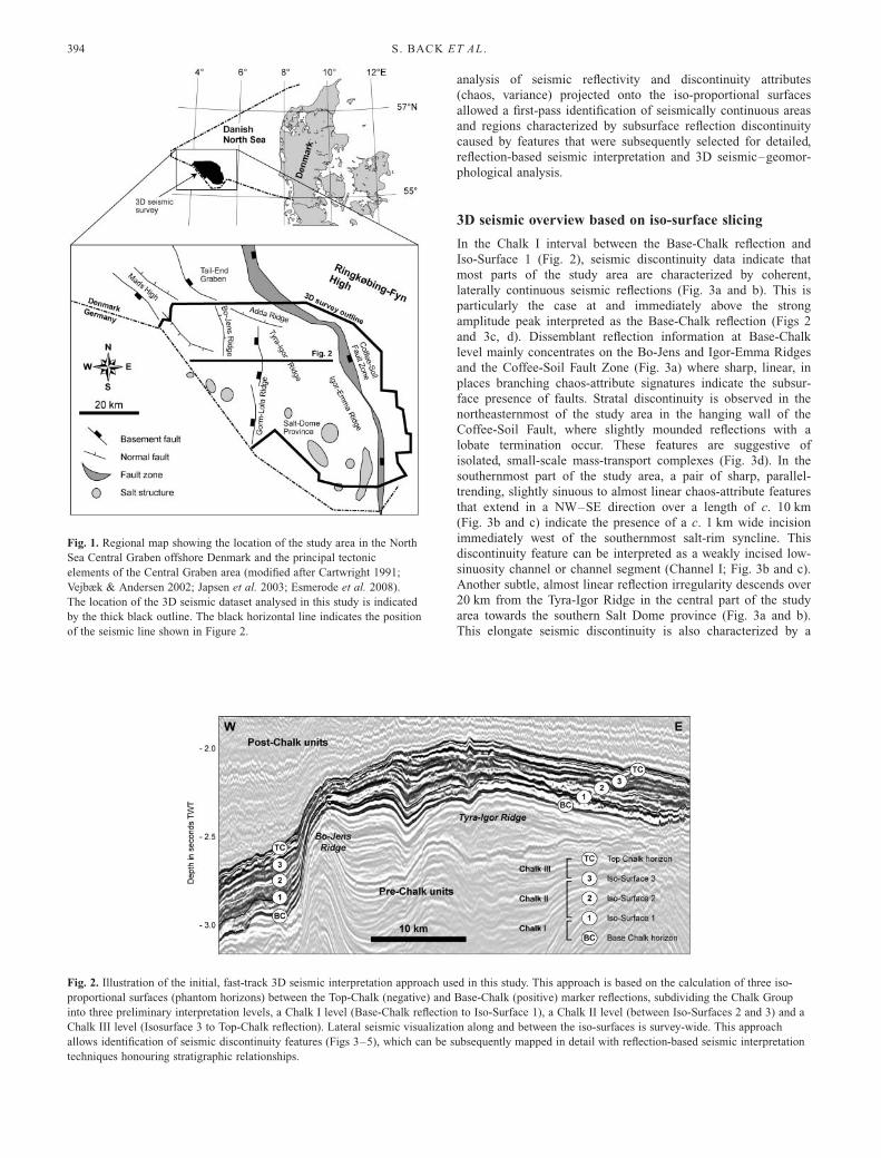
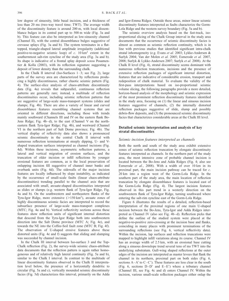
Fig. 4. Chalk II overview interpretation. (a) Chaos-attribute data extracted in Chalk II interval, documenting that most of the survey area is characterized
by discontinuous stratal configuration (grey to black areas). (b) Interpretation of discontinuity-slice data. Elongate linear to sinuous incisions interpreted as
channels in blue, mass-transport complexes in red. Blue arrows show downstream direction of channels as indicated by dendritic channel patterns
upstream; red arrows indicate mass-transport direction indicated by upslope headwall scarps and/or downslope folds and thrusts. (c) Close-up of sinuous
chaos-attribute pattern suggestive of intra-chalk channels between the Adda and Bo-Jens Ridges (location of close-up indicated in (a)). (d) Vertical
reflectivity images along sections W–W’ and X–X’ (location indicated in (c)) showing U- and V-shaped incisions interpreted as Channels III and IV.
(Note reflection pattern within Channel IV indicative of inner-levee deposits; for a detailed interpretation see Figs 6 and 7). (e) SW–NE-oriented mass-
transport complex with major internal folding located on the southern Tyra-Igor Ridge along section Y–Y’ (indicated in (b)). Yellow crosses indicate
incision feature above mass-transport complex. (f) ENE–WSW-oriented mass-transport complex on the eastern flank of the Tyra-Igor Ridge along section
Z–Z’ (location indicated in (b)). Yellow crosses as in (e).
3D SEISMIC GEOMORPHOLOGY IN THE CHALK GROUP 397
sidewalls or downlap onto the incision base (Fig. 6, sections A–A’
to D–D’). These units occur dominantly at the outer bends of the
channel thalweg, and are interpreted as inner-levee deposits (or
secondary banks and overbanks sensu Kolla et al. 2007). The
variable nature of the infill is also indicated by the numerous
reflection truncations that can be observed along the main channel
axis in a downslope direction (Fig. 6, Section F–F’).
Figure 7 illustrates the lateral variability of the channel infill
through time with a series of successive reflectivity surface slices
at given distances above the channel base. At the lowest
stratigraphic level (20 ms TWT above the main erosional base;
Fig. 7a, top), bow-shaped, subparallel reflections of variable
polarity characterize the outer bends of Channel IV. These
features correspond to the small-scale onlap and downlap units
interpreted in vertical section as inner-levee deposits (Fig. 6).
Polarity-based reflection tracing in a downslope direction reveals
a laterally migrating line pattern (Fig. 7a, bottom) suggestive of
a shift of the channel thalweg towards the channel centre with
time. Opposite the inflow point of Channel III, lobate reflections
of strong negative amplitude are interpreted as a small-scale
slump deposit that entered Channel IV from the eastern master
levee. Up section, 40 ms TWT above the incision base (Fig. 7b,
top), bow-shaped outer-bend reflections in the northern part of
the system are mainly the topward continuation of those of the
preceding interpretation level; however, they are of different
orientation in the central and southern part of Channel IV.
Downslope reflection tracing suggests that thalweg sinuosity,
migration and inner-levee development were concentrated at this
interpretation level on the central and southern part of the system
(Fig. 7b, bottom). At 60 ms TWT above the main erosional base
of Channel IV (Fig. 7c, top), all remaining outer-bend reflections
correspond to those of the previous interpretation levels (Fig. 7c,
bottom). Downslope reflection tracing indicates a broad, straight
channel thalweg flanked by elongate reflections of relatively high
lateral continuity (Fig. 7c, top). These reflections extend top-
wards beyond the confines of the master incision and overlie the
master levees (corresponding to the overspill units, Fig. 6). This
suggests that Channel IV was filled by this time and that
channelized flows could no longer be contained.
In comparison with the northern part of the study area, intra-
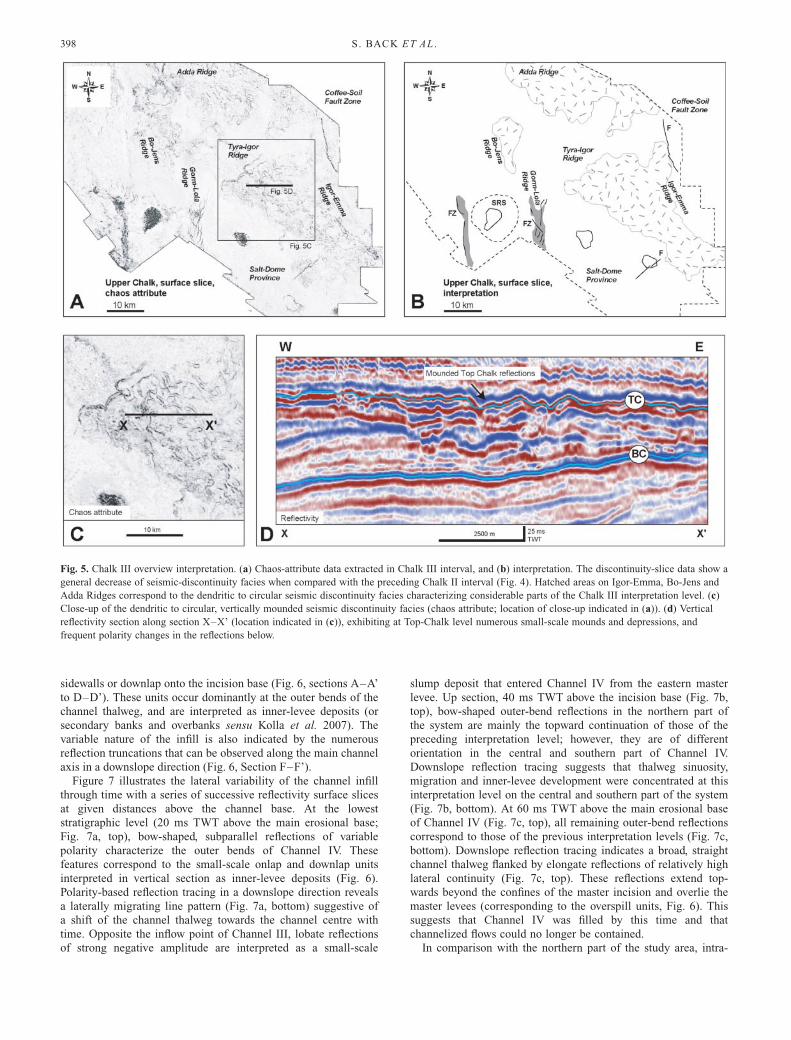
Fig. 5. Chalk III overview interpretation. (a) Chaos-attribute data extracted in Chalk III interval, and (b) interpretation. The discontinuity-slice data show a
general decrease of seismic-discontinuity facies when compared with the preceding Chalk II interval (Fig. 4). Hatched areas on Igor-Emma, Bo-Jens and
Adda Ridges correspond to the dendritic to circular seismic discontinuity facies characterizing considerable parts of the Chalk III interpretation level. (c)
Close-up of the dendritic to circular, vertically mounded seismic discontinuity facies (chaos attribute; location of close-up indicated in (a)). (d) Vertical
reflectivity section along section X–X’ (location indicated in (c)), exhibiting at Top-Chalk level numerous small-scale mounds and depressions, and
frequent polarity changes in the reflections below.
S. BACK ET AL .398

chalk channels in the south are less incised and thus more
difficult to detect. Figure 8 is a representative example of a
southern incision of c. 1 km width that descends the south-
western flank of Tyra-Igor Ridge in a westerly direction. This
incision apparently truncates reflections a few kilometres north
of a salt structure, before turning in a SSE direction whereupon
it enters the salt-rim syncline east of the Gorm-Lola Ridge (see
Fig. 4b, Channel VI). The geomorphology and internal seismic
character of this incision are fundamentally different from those
of the northern system described above. The southern example
lacks sinuosity and is strongly asymmetrical. Its southern flank is
generally steep and erosive, whereas its northern flank has a
lower dip and is only weakly confined to partly unconfined.
There are no outer levees flanking the incision, and there is no
indication of inner levees within the incision fill. Instead, the
infill gives rise to a semi-transparent seismic facies comprising
weak, but distinguishable low-amplitude reflections. These in-
dicate the presence of well-layered depositional units, which are
difficult to detect seismically if their polarity matches that of the
surrounding strata.
Distorted reflection packages suggestive of mass-transportcomplexes
A key observation in the study area is that the majority of
large-scale, arcuate, internally distorted seismic units interpreted
as gravity-driven mass-transport complexes are located on, or in
the immediate vicinity of the flanks of rising structures (inver-
Fig. 6. Detailed interpretation of the proximal part of Channel IV between the Bo-Jens, Tyra-Igor and Adda Ridges (for location see Fig. 4a and c).
Reflection picks defining the channel outline are indicated on vertical reflectivity sections by yellow crosses. Channel IV has an average width of 2.5 km,
with an erosional base cutting along a sinuous downslope trend several tens of milliseconds TWT into the underlying substratum. Prominent master levees
flank the channel in its northern, proximal part on both sides (sections A–A’ to C–C’), but are less clearly defined in the south (sections D–D’ and E–
E’). In places, inner levees (secondary banks and overbanks sensu Kolla et al. 2007) are developed within the infill of the master incision (sections A–A’
to D–D’), features that dominantly occur on the outer bends of the channel thalweg. The variable nature of the incision infill is also indicated by
numerous reflection truncations observed along the main channel axis in a downslope direction (section F–F’).
3D SEISMIC GEOMORPHOLOGY IN THE CHALK GROUP 399
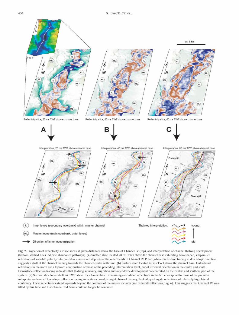
Fig. 7. Projection of reflectivity surface slices at given distances above the base of Channel IV (top), and interpretation of channel thalweg development
(bottom; dashed lines indicate abandoned pathways). (a) Surface slice located 20 ms TWT above the channel base exhibiting bow-shaped, subparallel
reflections of variable polarity interpreted as inner-levee deposits at the outer bends of Channel IV. Polarity-based reflection tracing in downslope direction
suggests a shift of the channel thalweg towards the channel centre with time. (b) Surface slice located 40 ms TWT above the channel base. Outer-bend
reflections in the north are a topward continuation of those of the preceding interpretation level, but of different orientation in the centre and south.
Downslope reflection tracing indicates that thalweg sinuosity, migration and inner-levee development concentrated on the central and southern part of the
system. (c) Surface slice located 60 ms TWT above the channel base. Remaining outer-bend reflections in the NE correspond to those of the previous
interpretation levels. Downslope reflection tracing indicates a broad, straight channel thalweg flanked by elongate reflections of relatively high lateral
continuity. These reflections extend topwards beyond the confines of the master incision (see overspill reflections, Fig. 6). This suggests that Channel IV was
filled by this time and that channelized flows could no longer be contained.
S . BACK ET AL .400

sion ridges, diapirs). These features can be very diverse in
external form, size and internal architecture (e.g. Figs. 3d and
4e, f). Probably the most obvious and, with an extent of around
150 km2, also the largest seismic discontinuity unit is observed
in the lower Chalk II interval east of a series of linked, cuspate
chaos-attribute features resembling major headwall scarps (sensu
Bull et al. 2009) between the Tyra-Igor and Igor-Emma Ridges
(MTC B; Fig. 4a, b and f). Although close to the limit of
seismic resolution, vertical displays across this discontinuity
unit indicate the presence of irregular reflection contacts
associated with high lateral and vertical amplitude variations. In
other settings, similar features have been interpreted as slump
deposits (e.g. Moscardelli & Wood 2008). The second largest,
arcuate seismic discontinuity unit of the study area is located at
the same stratigraphical level on the southwestern flank of Tyra-
Igor Ridge (MTC A; Fig. 4a, b and e), covering an area of
around 100 km2 (Fig. 9). In its distal parts, this unit exhibits
trains of wavy reflection distortions associated with prominent
lateral amplitude irregularities suggestive of intense stratal
folding (and possibly thrusting) in a compression-ridge setting.
In comparison with the large-scale mass-transport complex on
the eastern side of Tyra-Igor Ridge (MTC B; Fig. 4f), this
deposit lacks indications of a sharp, well-defined headwall scarp
in its most proximal portion (MTC A; Fig. 4a and b). However,
the considerable reflection distortion in its distal part also
suggests its origin as a slump, although the relatively undis-
turbed reflection pattern in its most proximal portion (Fig. 9a
and b) indicates (for this part of the system) only minor
downslope sliding.
Other seismic discontinuity packages interpreted as mass-
transport complexes include the small-scale, mounded dissem-
blant units (,20 km2 extent) documented in the Chalk I interval
in the northeasternmost part of the study area on the hanging
wall of the Coffee-Soil Fault (Fig. 3a, b and d). These units are
generally less than 30 ms (TWT) thick and characterized by
lateral reflection pinch-outs, lobate frontal terminations and an
irregular top commonly marked by downslope-oriented ridges
and scour-like features (Fig. 3d). These small-scale deposits are
Fig. 8. Channel VI in the south of the study
area descending the southwestern flank of
Tyra-Igor Ridge in a westerly direction (for
approximate location see Fig. 4b). This c.
1 km wide, strongly asymmetric incision
feature exhibits a steep, erosive southern
flank and a gentle northern flank that is
only weakly confined (partly unconfined).
The system lacks any sinuosity and
evidence for levees, and is filled by
subparallel- to parallel-bedded,
homogeneous sheet deposits, features that
are suggestive of a bottom-current
controlled contourite system.
Fig. 9. Depth map of the top of the second
largest mass-transport complex in the study
area, located on the SW flank of Tyra-Igor
Ridge. Vertical reflectivity sections A–A’
and B–B’ reveal prominent high-amplitude
reflections suggesting distortion of bedded
material, which are interpreted as
compressional ridges within the mass-
transport complex. (For cross-section Y–Y’
see Fig. 4e.) Horizon picks defining the top
of the mass-transport system are indicated
on the reflectivity sections by yellow
crosses.
3D SEISMIC GEOMORPHOLOGY IN THE CHALK GROUP 401
interpreted either as small-scale slump units or as debris-flow
deposits derived from unstable slopes further west.
Seismic discontinuity facies at Chalk III level
A seismic discontinuity facies associated with a generally
rugged, mounded reflection morphology characterizes the inter-
pretation level immediately below and at Top Chalk particularly
on the Adda and Igor-Emma Ridges (Figs 5 and 10a). Vertical
sections across the main zone of dissemblance (Figs 5d and 10b)
exhibit at Top-Chalk level numerous small-scale mounds and
depressions with a width of 100–300 m, a structural relief of up
to 25 ms (TWT), and frequent polarity changes in the strong,
highly discontinuous reflections below. Huuse (1999) has docu-
mented Top-Chalk features of comparable shape and dimension
on 2D high-resolution seismic reflection data in the Norwegian–
Danish Basin, interpreting these as possible surface karst struc-
tures. A difference between the features analysed by Huuse
(1999) and those of this study is the major reflection disruption
and lateral polarity variation in the reflection packages below the
Top-Chalk level (Figs 5d and 10b), in contrast to the rather
continuous, homogeneous internal reflection signature of the
Norwegian–Danish Basin features.
A comparison of the lateral distribution of the Top-Chalk
discontinuity facies in the study area with the seismic dissem-
blance features of the preceding Chalk II level (see Fig. 4)
indicates that the location of discontinuous Chalk III reflections
approximately corresponds to the sites of former mass wasting,
although much larger in area. To test whether the Chalk III
dissemblance facies could also be related to gravity-driven
processes, as opposed to an arguable interpretation as surface
karst (Huuse 1999) or possibly hypogenic subsurface karst (e.g.
sensu Palmer 1991), the approximate palaeo-relief at Chalk III
times was restored by flattening an auxiliary intra-Tertiary
horizon immediately above Top Chalk (Fig. 10b and c). Although
simple, this method seems appropriate in a setting characterized
at Chalk II level by a depositional thinning onto former structural
highs (e.g. Figs 4, 9 and 10; palaeo-highs interpretable as such if
exhibiting large-scale mass-transport systems on their flanks).
The flattening approach resulted in an eastward inclination (c.
1–28) of the Chalk III unit suggesting that the discontinuity
facies might have indeed formed on a palaeo-slope, an area that
could have been post-depositionally uplifted and tilted to its
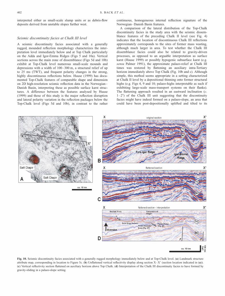
Fig. 10. Seismic discontinuity facies associated with a generally rugged morphology immediately below and at Top-Chalk level. (a) Landmark structure
attribute map, corresponding in location to Figure 5c. (b) Unflattened vertical reflectivity display along section X–X’ (section location indicated in (a)).
(c) Vertical reflectivity section flattened on auxiliary horizon above Top Chalk. (d) Interpretation of the Chalk III discontinuity facies to have formed by
gravity-sliding in a palaeo-slope setting.
S . BACK ET AL .402

present-day position at the crest of the Tyra-Igor Ridge. In the
context of the multitude of gravity-driven deposits documented
in the preceding Chalk II interval, it seems possible that during
Chalk III times a slope setting facilitated gravity-driven down-
slope movement (slumping, sliding or creep?) contributing to the
irregular Chalk III morphology and seismic facies (Fig. 10d).
However, considering the complexity of tectonic inversion in
time and space compared with the simplicity of the seismic-
flattening approach, other interpretations of the seismic disconti-
nuity facies at Chalk III level are not invalidated, and further
studies including borehole-core data are needed to determine the
exact nature of the dissemblant Top-Chalk unit.
Discussion
The seismic reflection data and interpretations presented in this
paper suggest strongly that the North Sea Chalk in the Central
Graben offshore Denmark contains a multitude of mass-transport
deposits. The majority of these are located on, or in the
immediate vicinity of tectonically active structures, in particular
on the flanks of ridges that formed in response to Late Cretac-
eous inversion (e.g. Vejbæk & Andersen 1987, 2002; Esmerode
et al. 2008). The most obvious mass-transport units are the large-
scale slumps and slides on the flanks of the Tyra-Igor and Igor-
Emma Ridges (e.g. Figs 4, 9 and 10); more subtle features are
small-scale slump or debris-flow deposits in the vicinity of the
Coffee-Soil Fault (e.g. Fig. 3d). Stratal thinning towards former
structural highs suggests that horizon flattening can be used as a
first-pass indicator for palaeo-slope settings (e.g. Fig. 10), but the
lack of well-defined palaeo-bathymetric reference data for the
Chalk Group limits a more detailed 3D restoration of the palaeo-
morphology (e.g. sensu Back et al. 2008). However, the wide-
spread inhomogeneity of seismic facies still documents that
much of the Chalk Group material in the Central Graben was
remobilized after deposition and transported by sliding or slump-
ing, or as channelized density flow (Figs 3–5). This clearly
contrasts with the classical view of a highly continuous, dom-
inantly parallel-bedded North Sea Chalk, but adds to studies that
previously identified considerable intra-chalk erosion, sediment
reworking and redeposition (e.g. Quine & Bosence 1991; Evans
et al. 2003; Lykke-Andersen & Surlyk 2004; Van der Molen et
al. 2005; Jarvis 2006; Esmerode et al. 2007, 2008; Surlyk &
Lykke-Andersen 2007; Surlyk et al. 2008).
A significant part of the very recent work on dynamic
sedimentation processes during the development of the North
Sea Chalk (e.g. Esmerode et al. 2007, 2008; Surlyk & Lykke-
Andersen 2007; Surlyk et al. 2008) has stressed the influence of
powerful, long-lived, contour-parallel bottom currents for the
development of many of the intra-chalk stratal irregularities, an
interpretation particularly reliant on the analysis of channel
geometries (see Esmerode et al. 2008; Surlyk et al. 2008; and
discussions therein). However, the quantity, extent, spatial dis-
tribution, variability in transport direction and seismic character
of unambiguously gravity-driven mass-transport complexes (i.e.
slides, slumps) documented in this study suggests a critical re-
evaluation of the main controlling factors for the deposition of
the North Sea Chalk of the Central Graben. With gravity-driven
sediment transport seemingly common, it appears likely that
turbid density flows contributed to the redeposition of chalk
strata. Such currents that could have been generated, for
example, from the dispersed head-parts of debris flows (Nemec
1990), or simply evolved from such flows whenever these
accelerated sufficiently to become fully turbulent (Hampton
1972; Ferentinos et al. 1988; Weirich 1989; Nemec 1990).
Following this line of argument, it is significant that the
orientation of the interpreted channel systems varies throughout
the study area, with the channels of the Chalk I interval trending
into southwesterly and southeasterly directions (Fig. 3), and the
channels of the Chalk II interval being oriented towards the
south, SE, east and west (Fig. 4). No channels were detected in
the Chalk III level. All channels of the Chalk I and Chalk II
interval trend approximately perpendicular to the palaeo-slope
(see e.g. channel base of section F–F’, Fig. 6, in relation to the
Top Chalk reflection); however, its has been noted before that a
palaeo-slope restoration in the Chalk is difficult in the absence of
a clear palaeo-bathymetric datum. The most prominent channel
system of the study area is the major southward-trending
Channel IV at Chalk II level shown in Figures 4, 6 and 7, which
is partly the same system as analysed and described by Esmerode
et al. (2008). The channel is branched in its upper part, with
tributaries descending from the Bo-Jens Ridge in the west and
the Adda Ridge in the NE, before combining into one large
channel that follows the course of the structurally defined
depression between the Bo-Jens and Tyra-Igor Ridges (Figs 2
and 4). A key departure from the interpretation of Esmerode et
al. (2008) is the documentation of a clear sinuosity of the main
Channel IV incision that is flanked on both sides by master
levees (Fig. 6), which suggests its exposure to (and possibly
initiation by) turbulent erosive flows. In addition, the infill of the
system comprises well-defined inner levees on the outer bends of
the channel thalweg (see Figs 6 and 7), which strongly indicates
that the master incision served after its initiation recurrently as a
conduit for turbulent density flows. Towards the top of the
incision, secondary overbanks extend beyond the confines of the
master channel covering the master levees (Figs 6b, c and 7c).
This is interpreted to reflect that most of the channel was filled
by this time and channelized flows could no longer be contained.
The starting points of the system on the flanks of Bo-Jens and
Adda-Ridges (Fig. 4) indicate that it might have been fed initially
by slumped material from the actively rising and locally failing
ridge slopes. Downslope, it was further supported by mass-
wasted material derived from channel-wall collapses. The appar-
ently strong incision of the feature suggests a considerable
erosive power of the system, possibly enhanced by the incorpora-
tion of failed chalk hardgrounds in density flows passing through
the channel. Thus, the northern channel system of the Chalk II
interval displays many of the architectural elements of a classic
gravity-driven deep-water turbidite system (e.g. sensu Deptuck et
al. 2003, 2007; Posamentier & Kolla 2003; Heinio & Davies
2007; Kolla et al. 2007), features that have, to our knowledge,
not yet been documented in the Chalk Group or in other
carbonate depositional environments.
In comparison with the northern system, the channels in the
south of the study area (e.g. Figs 4 and 8) are less confined and
less incised. An important discussion point is that the southern
Channel VI (Fig. 8) initially trends in a westerly direction (see
also Fig. 4), which is oblique to the general southeasterly
direction of the long-lived, contour-parallel bottom currents
proposed by Esmerode et al. (2008) and Surlyk et al. (2008).
However, after passing the northern flank of a salt structure, the
system turns to a SSE direction (see Fig. 4b), a flow direction
that is in line with the proposed bottom-current orientation of
Esmerode et al. (2008) and Surlyk et al. (2008). From seismic
data alone it can only be speculated that increased chalk
cementation around the salt structure acting together with a
syndepositional rise of the diapir may have constrained the
location of Channel VI, and that, in turn, a positive diapir relief
could have caused a local deflection of originally SSE-oriented
3D SEISMIC GEOMORPHOLOGY IN THE CHALK GROUP 403

bottom currents into a westerly direction. However, what is
clearly documented by the seismic reflection data is that Channel
VI generally lacks any sinuosity and evidence for levees, and
that the system is strongly asymmetrical and filled by subpar-
allel- to parallel-bedded, homogeneous sheet deposits. These
observations contradict an interpretation of the southern channel
as a turbidity-current feature; instead, they support its interpreta-
tion as a channel formed by bottom currents filled in laterally by
drift deposits.
In summary, the observation of significant stratal discontinuity
in the Chalk Group of the Danish part of the North Sea Central
Graben indicates that chalk sedimentation was strongly influ-
enced by submarine erosion, sediment transport and redeposition.
The mass-transport systems analysed in this study are only
mildly developed in the Chalk I interval, but reach a maximum
in the Chalk II and lower Chalk III levels (Fig. 11). In particular,
the major Chalk II slumps and slides that are located alongside
tectonically active inversion structures indicate that tectonically
induced, gravity-driven mass-transport processes contributed sig-
nificantly to the redistribution of chalk sediment. Additionally,
detailed analysis of the geomorphology and internal architecture
of the northern intra-chalk Channel IV (Figs 4, 6 and 7) suggests
that this system formed an important conduit for recurrent,
gravity-driven turbulent flows that transported failed chalk
material into the deeper chalk depocentres. However, at the same
stratigraphic level there are also incision features similar to
channels formed by bottom currents that have been documented
and analysed previously in the Chalk Group by, for example,
Surlyk & Lykke-Andersen (2007), Esmerode et al. (2008) and
Surlyk et al. (2008). Thus, it seems that a complex interaction of
inversion tectonics, gravity-driven processes and superimposed
bottom currents ultimately controlled chalk reworking and
redeposition in the study area, and that redeposited chalk can
consequently occur in a highly variable depositional fashion at
many locations in the North Sea Central Graben. Inferences on
whether the various reworked (allochthonous) chalk units have
reservoir properties different from autochthonous chalk deposits
are difficult to make from the use of seismic reflection data
alone, but the delineation of key study sites for integrating the
seismic interpretation results with high-resolution wireline-log
and core data is possible. Such a study has the potential to
identify unconventional hydrocarbon traps in previously unex-
plored chalk layers.
Conclusions
(1) The development of the Chalk Group of the North Sea
Central Graben was significantly influenced by mass-transport
processes. Slope instability on the flanks of tectonically active
structures generated in many places an oversteepened morph-
ology that failed, triggering gravity-driven deep-water mass
transport ranging from sliding and slumping to the generation of
high-energy, sediment-laden turbulent density flows.
(2) The detailed analysis of one major intra-chalk channel in
the north of the study area documents for the first time the
subsurface presence of a kilometre-scale, sinuous, leveed sedi-
ment-transport system that displays many of the architectural
elements known from siliciclastic deep-water turbidite systems.
This channel seems to have formed an important conduit for
recurrent turbulent flows that transported failed chalk material
into the deeper chalk depocentres.
(3) At the same stratigraphic level, there are other channels
that contrast with the northern channel in that they display
typical elements of contourite systems that were eroded by
powerful bottom currents and filled laterally by chalk drifts. If
integrated with the above conclusions, it seems likely that a
Fig. 11. Summary diagram of the depositional systems interpreted from seismic reflection discontinuities at different stratigraphic levels in the North Sea
Chalk Group offshore Denmark. (a) The Chalk I level is characterized by a generally high reflection continuity with only few seismic dissemblance
features interpreted as isolated channels or small-scale mass-transport deposits. (b) Reflection discontinuity reaches a maximum at Chalk II level.
Depositional systems interpreted at this level include (1) kilometre-scale slumps and slides located alongside tectonically active inversion ridges;
(2) sinuous, leveed turbidite channels; (3) incisions interpreted as bottom-current channels filled laterally by drift deposits. (c) Seismic reflection
discontinuity wanes in the Chalk III interval. Ridge areas exhibit a dendritic to circular, vertically mounded dissemblance facies interpreted to indicate
minor mass movement (slumping, sliding, creep?), surface karst (sensu Huuse 1999) or hypogenic karst (sensu Palmer 1991).
S . BACK ET AL .404
combination of active inversion tectonics, gravity-driven pro-
cesses and a superimposed bottom-current regime ultimately
controlled the reworking, redistribution and redeposition of the
Chalk Group strata in the North Sea Central Graben, which
makes generalized predictions of deposit type and its associated
reservoir properties difficult.
The authors thank Maersk Olie og Gas, Shell EPE Geological Services
and the DUC partners for initiating and supporting this study. The
contributions of many of their staff technically and/or by discussion is
particularly acknowledged. Personally thanked are T. Fronval, A. Uldall,
A. Wetzelaer and R. Kelly for their project input. The corrections,
comments and suggestions by reviewers M. Huuse, D. Evans and GSL
editor G. Hampson significantly improved an earlier version of the
manuscript, and their contribution to the final paper is highly appreciated.
Schlumberger is thanked for providing ‘PETREL’ under an Academic
User License Agreement. Seismic Micro-Technology is thanked for
providing ‘KINGDOM Software’ under an Educational User License
Agreement. This study is a spin-off of project DINGO (RE 2697/3-1)
funded by the Deutsche Forschungsgemeinschaft (DFG).
References
Back, S., Strozyk, F., Kukla, P.A. & Lambiase, J.J. 2008. 3D restoration of
original sedimentary geometries in deformed basin fill, onshore Brunei
Darussalam, NW Borneo. Basin Research, 20, 99–117.
Brewster, J. & Dangerfield, J.A. 1984. Chalk fields along the Lindesnes Ridge,
Eldfisk. Marine and Petroleum Geology, 1, 239–278.
Bromley, R.G. & Ekdale, A.A. 1987. Mass transport in European Cretaceous
chalk; fabric criteria for its recognition. Sedimentology, 34, 1079–1092.
Bull, S., Cartwright, J. & Huuse, M. 2009. A review of kinematic indicators
from mass transport complexes using 3D seismic data. Marine and Petroleum
Geology, 26, 1132–1151.
Cartwright, J. 1989. The kinematics of inversion in the Danish Central Graben.
In: Cooper, M.A. & Williams, G.D. (eds) Inversion Tectonics. Geological
Society, London, Special Publications, 44, 153–175.
Cartwright, J. 1991. The kinematic evolution of the Coffee Soil Fault. In:
Roberts, A.M., Yielding, G. & Freeman, B. (eds) The Geometry of Normal
Faults. Geological Society London, Special Publications, 56, 29–40.
Clausen, O.R. & Huuse, M. 1999. Topography of the Top Chalk surface on- and
offshore Denmark. Marine and Petroleum Geology, 16, 677–691.
Deptuck, M.E., Steffens, G.S., Barton, M. & Pirmez, C. 2003. Architecture
and evolution of upper fan channel-belts on the Niger Delta slope and in the
Arabian Sea. Marine and Petroleum Geology, 20, 649–676.
Deptuck, M.E., Syvester, Z., Pirmez, C. & O’Byrne, C. 2007. Migration–
aggradation history and 3-D seismic geomorphology of submarine channels
in the Pleistocene Benin-major Canyon, western Niger Delta slope. Marine
and Petroleum Geology, 24, 406–433.
Esmerode, E.V., Lykke-Andersen, H. & Surlyk, F. 2007. Ridge and valley
systems in the Upper Cretaceous chalk of the Danish Basin: contourites in an
epeiric sea. In: Viana, A.R. & Rebesco, M. (eds) Economic and
Palaeoceanographic Significance of Contourite Deposits. Geological Society,
London, Special Publications, 276, 265–282.
Esmerode, E.V., Lykke-Andersen, H. & Surlyk, F. 2008. Interaction between
bottom currents and slope failure in the Late Cretaceous of the southern
Danish Central Graben, North Sea. Journal of the Geological Society,
London, 165, 55–72.
Evans, D.J., Hopson, P.M., Kirby, G.A. & Bristow, C.R. 2003. The development
and seismic expression of synsedimentary features within the Chalk of
southern England. Journal of the Geological Society, London, 160, 797–813.
Ferentinos, G., Papatheodorou, G. & Collins, M.B. 1988. Sediment transport
processes on an active submarine fault escarpment, Gulf of Corinth, Greece.
Marine Geology, 83, 43–61.
Hampton, M.A. 1972. The role of subaqueous debris flow in generating turbidity
currents. Journal of Sedimentary Petrology, 42, 775–793.
Hancock, J.M. 1975. The petrology of the Chalk. Proceedings of the Geologists’
Association, 86, 499–535.
Hardman, R.F.P. 1982. Chalk reservoirs of the North Sea. Bulletin of the
Geological Society of Denmark, 30, 119–137.
Hatton, I.R. 1986. Geometry of allochthonous Chalk Group members, Central
Trough, North Sea. Marine and Petroleum Geology, 3, 79–98.
Heinio, P. & Davies, R.J. 2007. Knickpoint migration in submarine channels in
response to fold growth, western Niger Delta. Marine and Petroleum Geology,
24, 434–449.
Huuse, M. 1999. Detailed morphology of the Top Chalk surface in the eastern
Danish North Sea. Petroleum Geoscience, 5, 303–314.
Japsen, P., Britze, P. & Anderson, C. 2003. Upper Jurassic–Lower Cretaceous
of the Danish Central Graben: structural framework and nomenclature.
Geological Survey of Denmark and Greenland Bulletin, 1, 233–246.
Jarvis, I. 2006. The Santonian–Campanian phosphatic chalks of England and
France. Proceedings of the Geologists’ Association, 117, 219–237.
Kennedy, W.J. 1987. Sedimentology of Late Cretaceous–Palaeocene chalk
reservoirs, North Sea Central Graben. In: Brooks, J. & Glennie, K.W. (eds)
Petroleum Geology of North West Europe. Graham & Trotman, London, 469–
481.
Kolla, V., Posamentier, H.W. & Wood, L.J. 2007. Deep-water and fluvial
sinuous channels—Characteristics, similarities and dissimilarities, and models
of formation. Marine and Petroleum Geology, 24, 388–405.
Lykke-Andersen, H. & Surlyk, F. 2004. The Cretaceous–Palaeogene boundary
at Stevns Klint, Denmark: inversion tectonics or sea-floor topography?
Journal of the Geological Society, London, 161, 343–352.
Moscardelli, L. & Wood, L.J. 2008. New classification system for mass transport
complexes in offshore Trinidad. Basin Research, 20, 73–98.
Nemec, W. 1990. Aspects of sediment movement on steep delta slopes. In:
Colella, A. & Prior, D.B. (eds) Coarse-grained Deltas. International
Association of Sedimentologists, Special Publications, 10, 29–73.
Palmer, A.N. 1991. Origin and morphology of limestone caves. Geological Society
of America Bulletin, 103, 1–21.
Posamentier, H. & Kolla, V. 2003. Seismic geomorphology and stratigraphy of
depositional elements in deep-water settings. Journal of Sedimentary Re-
search, 73, 367–388.
Quine, M. & Bosence, D. 1991. Stratal geometries, facies and sea-floor erosion in
Upper Cretaceous chalk, Normandy, France. Sedimentology, 38, 1113–1152.
Skirius, C., Nissen, S., et al. 1999. 3-D seismic attributes applied to carbonates.
Leading Edge, 18, 384–393.
Surlyk, F. 1997. A cool-water carbonate ramp with bryozoan mounds: Late
Cretaceous–Danian of the Danish Basin. In: James, N.P. & Clarke, J.A.D.
(eds) Coolwater Carbonates. SEPM Special Publications, 56, 293–307.
Surlyk, F. & Lykke-Andersen, H. 2007. Contourite drifts, moats and channels in
the Upper Cretaceous Chalk of the Danish Basin. Sedimentology, 54, 405–
422.
Surlyk, F., Dons, T., Clausen, C.K. & Higham, J. 2003. Upper Cretaceous. In:
Evans, D., Graham, C., Armour, A. & Bathurst, P. (eds) The Millennium
Atlas: Petroleum Geology of the Central and Northern North Sea. Geological
Society, London, 213–233.
Surlyk, F., Jensen, S.K. & Engkilde, M. 2008. Deep channels in the
Cenomanian–Danian Chalk Group of the German North Sea sector: Evidence
of strong constructional and erosional bottom currents and effect on reservoir
quality distribution. AAPG Bulletin, 92, 1565–1586.
Van der Molen, A.S., Dudok van Heel, H.W. & Wong, T.E. 2005. The
influence of tectonic regime on chalk deposition: examples of the sedimentary
development and 3D-seismic stratigraphy of the Chalk Group in the Nether-
lands offshore area. Basin Research, 17, 63–81.
Vejbæk, O.V. & Andersen, C. 1987. Cretaceous–early Tertiary inversion
tectonism in the Danish Central Trough. Tectonophysics, 137, 221–238.
Vejbæk, O.V. & Andersen, C. 2002. Post mid-Cretaceous inversion tectonics in
the Danish Central Graben—regionally synchronous tectonic events? Bulletin
of the Geological Society of Denmark, 49, 129–144.
Weirich, F.H. 1989. The generation of turbidity currents by subaerial debris flows.
Geological Society of America Bulletin, 101, 278–291.
Received 29 March 2010; revised typescript accepted 2 August 2010.
Scientific editing by Gary Hampson.
3D SEISMIC GEOMORPHOLOGY IN THE CHALK GROUP 405

The Geological Society of London, Burlington HouseLaunch of the NERC Long-term Co-evolution of Life and the PlanetProgramme
Convenors:
Professor Tim Lenton, University of East AngliaDr Graham Shields, University College LondonProfessor Andrew Watson, University of East Anglia
Keynote speakers include:
Dr James Lovelock, Independent scientistProfessor Lynn Margulis, University of Massachusetts
The Earth that sustains us today was born out of a few remarkablerevolutions, started by evolutionary innovations and marked by globalenvironmental consequences, including abrupt rises in oxygen andextreme glaciations. The coupled evolution of life and the planet hascontinued up to the present, and now includes the planet-reshapingactivities of our species.
This two-day discussion meeting will showcase recent progress inunderstanding the development of the Earth as a system. The meeting will outline how new science can help in tying down critical uncertainties,regarding the nature and timing of past events. Finally, it will explore how an improved understanding of life and the planet in the past can help us achieve future sustainability.
Life and the Planet New perspectives in Earth system science
5th and 6th May 2011
Call for posters
T FE W