3D Printed Smart Molds for Sand Casting - link.springer.com · 3D PRINTED SMART MOLDS FOR SAND...
12
3D PRINTED SMART MOLDS FOR SAND CASTING Jason Walker, Evan Harris, Charles Lynagh, Andrea Beck, Brian Vuksanovich, Brett Conner, and Eric MacDonald Advanced Manufacturing Research Center, Youngstown State University, Youngstown, OH, USA Rich Lonardo Youngstown Business Incubator, Youngstown, OH, USA Jerry Thiel University of Northern Iowa, Cedar Falls, IA, USA Kirk Rogers GE Additive Customer Experience Center, General Electric, Pittsburgh, PA, USA Copyright Ó 2018 The Author(s). This article is an open access publication https://doi.org/10.1007/s40962-018-0211-x Abstract Additive manufacturing, also commonly referred to as 3D printing, stands to transform sand casting with binder jetting technology that can create sand molds with unmatched geometric complexity. With printed sand molds, castings can be optimized with regard to the strength- versus-weight trade-off and structures such as periodic lattices are now available within molds that are not pos- sible with traditional casting technology. However, an increase in design complexity invites more challenges in terms of understanding and managing both the thermody- namics and physics of the casting process. Simulations of castings are more important than ever, and empirical in situ sensor data are required to validate high fidelity computer modeling (e.g., MAGMASOFT Ò ). One novel solution is to leverage the design freedom of CAD-based solid modeling to introduce unique mold features specifi- cally for housing sensors (Internet of Things) within the mold to enable the collection of a diversity of data at manifold locations: temperature, pressure, moisture, gas chemistries, motion of the molds and internal cores (shifting or rotation), and magnetic field. This report describes a proof of concept in which unprecedented levels of process monitoring were integrated—both wirelessly and wired—at strategic locations throughout a printed mold and inside of internal cores. The collected data were used to validate the quality of a casting in situ as well as to provide feedback for optimizing the casting process, mold design, and simulations. A trade-off was explored between sensor survivability and disposability. Keywords: 3D printing, additive manufacturing, electronics, sensing, simulation Introduction Sand casting is an economical metal forming process that has been employed to manufacture metal objects since the Shang Dynasty of China over 3000 years ago. 1 Relative to other forms of casting, sand casting provides a wide range of sizes, complexity, and types of metal alloys. Conse- quently, the size of the worldwide casting market recently increased to over 100 million metric tons 19 with sand casting as the predominant method of casting. 24 The growth and importance of this age-old industry require the leveraging of the latest quality and process controls as well as advances in mold, core, and pattern production to meet global demand and to maintain technical vitality. Additive manufacturing (AM) or 3D printing emerged as a new manufacturing method since the 1980s, but has gen- erally been limited to production of prototypes. However, the benefits of 3D printing for the casting industry were identified early. 5 The capability to fabricate complex part International Journal of Metalcasting
-
Upload
hoangtuyen -
Category
Documents
-
view
225 -
download
0
Transcript of 3D Printed Smart Molds for Sand Casting - link.springer.com · 3D PRINTED SMART MOLDS FOR SAND...

3D PRINTED SMART MOLDS FOR SAND CASTING
Jason Walker, Evan Harris, Charles Lynagh, Andrea Beck, Brian Vuksanovich, Brett Conner, and Eric MacDonaldAdvanced Manufacturing Research Center, Youngstown State University, Youngstown, OH, USA
Rich LonardoYoungstown Business Incubator, Youngstown, OH, USA
Jerry ThielUniversity of Northern Iowa, Cedar Falls, IA, USA
Kirk RogersGE Additive Customer Experience Center, General Electric, Pittsburgh, PA, USA
Copyright � 2018 The Author(s). This article is an open access publication
https://doi.org/10.1007/s40962-018-0211-x
Abstract
Additive manufacturing, also commonly referred to as 3D
printing, stands to transform sand casting with binder
jetting technology that can create sand molds with
unmatched geometric complexity. With printed sand molds,
castings can be optimized with regard to the strength-
versus-weight trade-off and structures such as periodic
lattices are now available within molds that are not pos-
sible with traditional casting technology. However, an
increase in design complexity invites more challenges in
terms of understanding and managing both the thermody-
namics and physics of the casting process. Simulations of
castings are more important than ever, and empirical
in situ sensor data are required to validate high fidelity
computer modeling (e.g., MAGMASOFT�). One novel
solution is to leverage the design freedom of CAD-based
solid modeling to introduce unique mold features specifi-
cally for housing sensors (Internet of Things) within the
mold to enable the collection of a diversity of data at
manifold locations: temperature, pressure, moisture, gas
chemistries, motion of the molds and internal cores
(shifting or rotation), and magnetic field. This report
describes a proof of concept in which unprecedented levels
of process monitoring were integrated—both wirelessly
and wired—at strategic locations throughout a printed
mold and inside of internal cores. The collected data were
used to validate the quality of a casting in situ as well as to
provide feedback for optimizing the casting process, mold
design, and simulations. A trade-off was explored between
sensor survivability and disposability.
Keywords: 3D printing, additive manufacturing,
electronics, sensing, simulation
Introduction
Sand casting is an economical metal forming process that
has been employed to manufacture metal objects since the
Shang Dynasty of China over 3000 years ago.1 Relative to
other forms of casting, sand casting provides a wide range
of sizes, complexity, and types of metal alloys. Conse-
quently, the size of the worldwide casting market recently
increased to over 100 million metric tons19 with sand
casting as the predominant method of casting.24 The
growth and importance of this age-old industry require the
leveraging of the latest quality and process controls as well
as advances in mold, core, and pattern production to meet
global demand and to maintain technical vitality.
Additive manufacturing (AM) or 3D printing emerged as a
new manufacturing method since the 1980s, but has gen-
erally been limited to production of prototypes. However,
the benefits of 3D printing for the casting industry were
identified early.5 The capability to fabricate complex part
International Journal of Metalcasting

geometries using layer-by-layer deposition as opposed to
traditional subtractive manufacturing now enables pro-
duction of molds, cores, and patterns that would be
otherwise impossible to create without 3D printing.2 One
important use of AM in the casting industry is 3D printed
sand molds which provide complex cavities, good dimen-
sional accuracies, the ability to insert components within
the casting and/or mold, and an increased freedom in the
design of the metal delivery system (gating, sprue, risers,
etc.). Sand printers use binder jetting technology to ink jet a
binder resin into a catalyst-mixed sand. After printing a
layer, a new layer of sand is re-coated over the previous
layers and the process repeats until the mold and/or cores
are completed. The furan binder chemistry typically used
involves a condensation-type curing and cross-linking
reaction which are both exothermic and chromophoric. The
temperature increases in the mold as it cures are generally
less than 20 �C3 which could allow for the survival of
electronics or sensors inserted into the mold during
printing.
More generally, substantial research has been focused on
3D printed sand molds including the material systems (e.g.,
binders and silica),7,18,21 properties such as surface finish
and porosity,2,15,22 complex multi-material structures,16,17
modeling of the process12 and even sensing in smart sand
molds8 in which temperature sensors were inserted into 3D
printed sand molds, and the survival and utility of the
sensors were evaluated. An entire community has resear-
ched ink jetting, the foundational process of binder jetting,
and the process is well understood and modeled.6,9,13
While the inherent benefit of AM-enabled casting is the
freedom of geometry, the accompanying challenge is the
increased complexity of the casting process and potential
reduction in part manufacturability. To overcome the
challenges, casting simulations are required to predict the
flow of metal potentially causing entrapment of gases or
erosion of sand from interior surfaces. In the context of 3D
printed molds, simulations are required with the nearly
unlimited design freedom enabled by 3D printed molds.
Furthermore, the resulting complex surfaces of the cavity
within the mold can lead to difficult-to-predict heat dissi-
pation which directly affects solidification. As shown in
Figure 1, increased complexity and large surface areas can
easily result in casting problems including premature
solidification and formation of such defects as cold-shuts
and lack of fusion. Lattices with smaller struts and there-
fore higher surface area (Figure 1, right) tend to solidify
too quickly, while lattices with a larger strut size and lower
surface area (Figure 1, left) fill completely despite the two
designs having the same metal volume. This example
shows both the profound benefits of AM-enabled casting
with geometries not previously possible while simultane-
ously highlighting the challenges and motivation for high
fidelity simulations and sensing.
Design of an Instrumented 3D Printed Sand Mold
This effort included leveraging an ‘‘Internet of Things’’
strategy for nontraditional sensing of AM-enabled castings
(a) in molds and (b) in a core in order to collect data to fuel
the analytics necessary to advance in situ evaluation, model
validation, and casting qualification. In concert with
advances in modeling, the comprehensive collection and
integration of process measurements will enable improved
simulations, in situ quality control, and possibly expedite
the qualification of casting designs and mold printing
processes (rather than resource-consuming physical trial-
and-error tests). Wired thermocouples have only infre-
quently been published in research with examples includ-
ing,4,8,10 but the use of these sensors is common knowledge
in the foundry industry to optimize casting processes—
albeit not documented in open literature. Alternatively,
Bluetooth systems have been improving over the last two
decades to the point now that a sensor system with an ARM
processor (used in most smartphones as of 2017), a Blue-
tooth radio, and an arsenal of miniaturized sensors can be
now be integrated onto a small printed circuit board that is
smaller than a postage stamp. The inevitable marriage of
this Internet of Things sensing capability with the ancient
art of sand casting has not been reported to the best of the
authors’ knowledge and is presented here with a sensor
system including 12 degrees of sensing. Specific cavities
were included in the molds to integrate sensors and collect
high fidelity data including environmental metrics (tem-
perature, pressure, humidity), acceleration, rotation, and
magnetic flux.
Figure 1. Complex aluminum structures with varyingdegrees of casting success. Left: Successful latticecasting of large strut (9.53 mm diameter) gyroid; right:incomplete gyroid casting with smaller strut sizes(6.35 mm diameter). Both castings had designed exter-nal dimensions of 63.5 9 63.5 9 139.7 mm and mass0.5 kg.
International Journal of Metalcasting

In-Mold Sensing for Casting Process SimulationStudies (Wired Thermocouples)
To improve the understanding of the physics of complex
castings, an instrumentation methodology was created in
which high temperature type K thermocouples were
inserted into purpose-designed slots within a parting line at
a variety of depths from the cavity. All thermocouples
(GeoCorp, Inc, Huron, OH) were factory calibrated and
verified to meet the special limits of error tolerances of
ASTM E230. The first objective of the thermocouples was
to set up a correlation baseline between the experimental
setup and the simulation model. The second objective of
the temperature data (versus distance) was to identify the
operational region in sand molds for the integration of
wireless electronics. Three scenarios exist for the posi-
tioning of the electronics:
1. in a location where the temperature never exceeds
the maximum operating temperature of the circuit
(85 �C) and data collection would be continuous,
2. in a location where the temperature would exceed
the operating temperature but not the maximum
storage temperature (150 �C) allowing for a short
duration of data collection and guaranteeing the
survival and recyclability of the circuits, or
3. in a location where both the maximum operating
and storage temperatures would be exceeded but
in closer proximity to the cavity providing more
direct data acquisition but for only a short
period—until the sensor is sacrificed.
The final case would require immediate wireless commu-
nication as recovery of the circuits at shakeout would not
be possible. However, the data collected could be in dif-
ficult-to-reach locations in a mold such as an internal core.
The aim of the thermocouple study was to provide the
appropriate distances from the cavity to determine the
positioning of the wireless sensors.
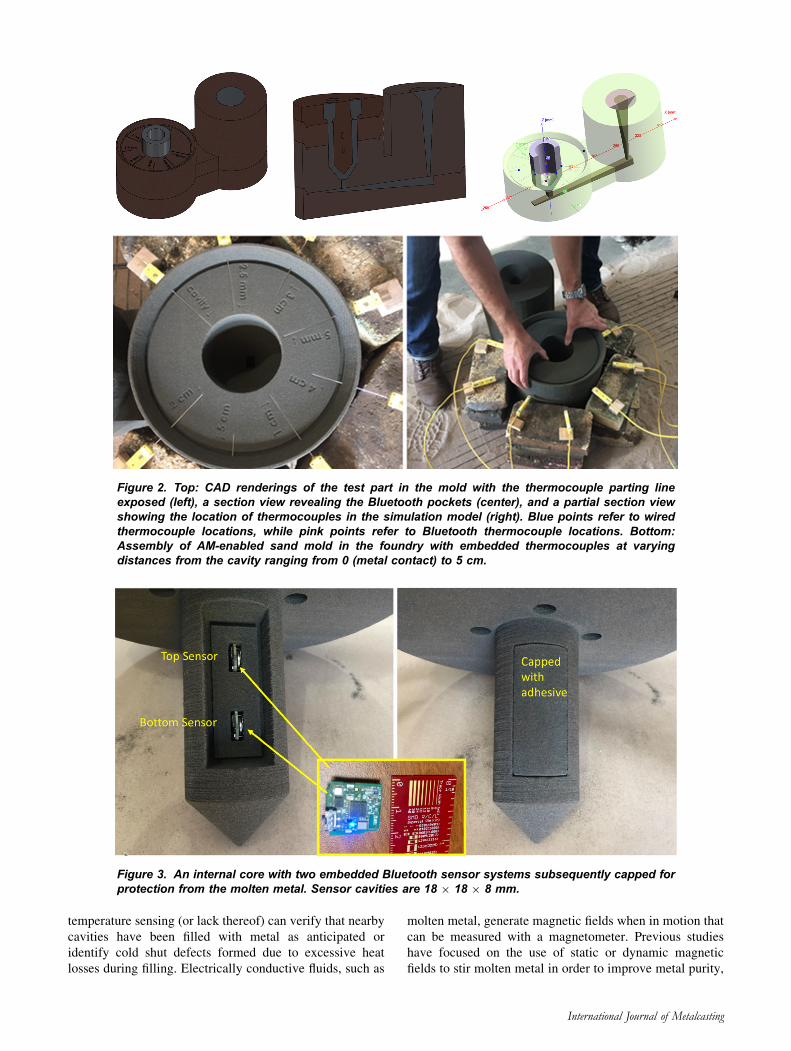
Figure 2 illustrates a 3D printed sand mold with thermo-
couple cavities at varying distances from a dummy casting
of a hollow cylinder. Eight thermocouples were included
within the parting line in the main mold structure. One
thermocouple was placed at the mold–metal interface such
that during the casting molten aluminum was in contact
with the thermocouple. Data from this thermocouple were
collected and presented with the knowledge that the cali-
bration may have been compromised the moment molten
aluminum contacted the sensor. The other seven thermo-
couples were increasingly spaced from the cavity in a
staggered manner at 2.5, 5, 10, 20, 30, 40, and 50 mm
rotating clockwise as shown in the bottom left of Figure 2.
Figure 2, bottom right, shows the thermocouples encased
with continued assembly of the mold. One final molding
piece capped these off suspending a vertical core within the
cavity. Data were collected during the 24 h after the end of
pouring and included four measurements per second for the
first 1.5 h and one measurement every minute for the next
22.5 h. This allowed for manageable data files while
maintaining fidelity during the period of more thermal
activity.
In-Core Wireless Sensing
The continuous technological advances in miniaturization
of electronics and sensors enable a complete computational
platform with a radio and an array of sensors in a footprint
that can be easily accommodated within a sand mold or
core. Dialog IoT Sensor systems include an ARM proces-
sor with substantial computational bandwidth, but more
importantly the system includes a low power Bluetooth
radio which can allow for the collection of data in difficult-
to-reach positions within a sand mold or core and include
sensing for:
1. three axes of magnetic field,
2. an inertial measurement unit providing three axes
each of rotation and acceleration, and
3. an environmental sensor with relative humidity,
pressure, and temperature.
These commercial Bluetooth sensor systems can be buried
within cores and are sufficiently inexpensive to be con-
sidered disposable. As a casting is poured, the metal that
will surround the core will inhibit radio frequency com-
munication required to transmit collected sensor data. In
the case of the experimental casting, there was a sand-only
path for the signal to exit the mold even after the risers had
filled and the casting completed. The small electronics
were not expected to survive beyond several minutes.
Temperature increase was simulated for the sensor cavity
which was predicted to exceed 350 �C at 750 s after the
casting—well above the maximum sustained storage tem-
peratures of 150 �C (predicted to exceed at 175 s) and
maximum operating temperature of 85 �C (predicted to
exceed at 110 s). However, the electronics were expected
to tell the story of what had occurred to the core in the early
stages of the pour (first 180 s) before the electronics were
affected by the harsh conditions. The sensors are shown in
Figure 3 before and after encapsulation in the sand core.
The multi-sensor electronic unit, shown in center, costs
approximately $45 USD and includes all of the afore-
mentioned sensors, as well as an on-chip processor (used in
most contemporary cell phones) to read the sensors and
transmit data. At this price point, the multi-sensor elec-
tronic unit is easily considered disposable for low volume
research applications and could be manufactured in-house
at an even lower cost.
Among the different types sensors that can be provided in a
miniaturized format, linear acceleration and rotation can be
used to measure relative motion of mold components
including identifying potential core shifts. In situ
International Journal of Metalcasting
temperature sensing (or lack thereof) can verify that nearby
cavities have been filled with metal as anticipated or
identify cold shut defects formed due to excessive heat
losses during filling. Electrically conductive fluids, such as
molten metal, generate magnetic fields when in motion that
can be measured with a magnetometer. Previous studies
have focused on the use of static or dynamic magnetic
fields to stir molten metal in order to improve metal purity,
Figure 2. Top: CAD renderings of the test part in the mold with the thermocouple parting lineexposed (left), a section view revealing the Bluetooth pockets (center), and a partial section viewshowing the location of thermocouples in the simulation model (right). Blue points refer to wiredthermocouple locations, while pink points refer to Bluetooth thermocouple locations. Bottom:Assembly of AM-enabled sand mold in the foundry with embedded thermocouples at varyingdistances from the cavity ranging from 0 (metal contact) to 5 cm.
Figure 3. An internal core with two embedded Bluetooth sensor systems subsequently capped forprotection from the molten metal. Sensor cavities are 18 9 18 9 8 mm.
International Journal of Metalcasting

reduce solidification defects, control grain size, and control
crystal orientation.11,20,24 However, another previous study
examined the use of a magnetic probe to measure melt
velocity and mass transfer.14 As molten metal was passed
around a permanent magnetic cylinder, a changing voltage
was read and translated into velocity and mass transfer.
One potential application of measuring magnetic fields in
castings is to provide an immediate and indirect detection
of metal in runners—two sensors of which at a known
separation could provide an indication of melt velocity.
To verify that wireless signals can be reliably transmitted
through furan resin bonded sand preliminary experiments
were completed as shown in Figure 4. Spherical sand
cores were created with varying diameters to measure the
attenuation of the wireless signals through the sand and
binder system. Although the wireless connection could be
maintained through the bonded sand, a slight reduction in
signal strength was recorded from the sensors, embedded
up to 14 cm deep. Care must be taken then for large
molds that could result in significant attenuation and
disconnections between a data recording device and the
embedded sensors. Furthermore, the distance between the
recording device and the mold also plays a significant
factor in signal reception. The closer the recording device
is to the mold, the better in terms of the reliable collec-
tion of data. Future work will further investigate critical
values related to mold thickness, receiver distance, and
signal strength.
Results and Discussion
The results of this effort can be separated into two sec-
tions:1 the thermocouple comparison with MAGMA-
SOFT� which shows that both physical instrumentation
and simulation are necessary to gain a strong understanding
of the process physics and2 a demonstration of the diversity
of sensor data which can be collected in an internal core
with wireless sensors—providing data acquisition, to the
best of the authors’ knowledge, never previously available.
The sample casting is shown in Figure 5. In the picture,
two data acquisition devices are elevated above the mold
on a step ladder and successfully collected data from the
embedded Bluetooth sensors starting 2 h prior to the
casting and lasting until approximately 2 min after pouring.
The duration of the pour—melt first entering the sprue until
all risers were filled—was 11 s, and Bluetooth data were
continuously collected on the two sensors for 115 and
135 s afterward until each sensor expired.
Embedded Wired Thermocouples
Eight type K thermocouples were placed into the mold
along a parting line in prefabricated slots at varying dis-
tances from the casting cavity. Here, the use of computer
aided design principles and 3D printing for mold fabrica-
tion enables unprecedented control of thermocouple
placement. Thermocouple data were collected before,
throughout, and for several hours after pouring. Similarly,
temperature profiles were calculated in MAGMASOFT�
through the use of virtual thermocouples placed at match-
ing locations (refer to Figure 2). Small discrepancies
between experimental and simulated curves could be
attributed to inexact ambient conditions, unaccounted heat
losses during transfer of metal to the mold, and lack of
experimentally verified thermophysical properties of the
3D printed sand system used in this experiment. Overall, as
shown in Figure 6, there is a strong agreement between
predicted and actual temperature distributions throughout
the mold over a relatively long period of time. Such
agreement between data at the thermocouple locations
demonstrates casting process simulation as an indispens-
able tool for studying the multi-physics of the entire metal
casting system.
Second order temperature effects are also seen early in the
thermal evolution as a shift in the temperature wave that
propagates through the mold. In the close-up Figure 7, the
effect is easily seen in the experimental data. Here, it
appears as an interruption in the temperature curve
Figure 4. Spherical sand cores used for evaluation of electromagnetic propagation of Bluetooth signalsthrough the sand media (left) and attenuation with dB versus depth in centimeters (right).
International Journal of Metalcasting

approximately between 80 and 90 �C. In the simulated
data, a similar second order effect is seen although it is
significantly less pronounced and occurs at a slightly
higher temperature—approximately 100 �C. These effects
are highlighted with red circles in Figure 7. A possible
explanation for this effect may be evaporation of moisture
in the mold as the temperature rises, while the difference
between the experiment and simulation may be
attributable to the difficulty in quantifying and simulating
moisture content within the mold and its surroundings.
Bluetooth Sensors Within Difficult-to-AccessCores
The Bluetooth sensor systems are capable of operating to a
maximum of 85 �C and can be stored up to 150 �C. In the
castings, both locations of the sensor systems were 2.27 cm
Figure 5. Casting with both wired and wireless in situ sensors.
Figure 6. Comparison of experimental and simulatedcooling curves recorded at varying distances from thecasting cavity.
Figure 7. Close-up showing second order effects seen in both simulation andexperiment.
International Journal of Metalcasting

from the metal cavity and consequently were not expected
to survive in an aluminum casting with molten metal
poured at 700 �C. MAGMASOFT� simulations estimated
a peak temperature at the site of the electronics to be
400 �C at 750 s (Figure 8) with the circuit board slightly
protected within a small air cavity. The temperature was
estimated to reach 85 �C after 100 s and 150 �C after 155 s
resulting in the complete destruction of the chip, the bat-
tery, and the depopulation of the circuit board with sol-
dering reflow. As predicted, the two circuits operated for
115 and 135 s after the start of the pour before succumbing
to the high temperature. As with the wired thermocouples,
the simulated temperature curve closely tracked the mea-
surements by the Bluetooth sensors until the sensors were
no longer capable of recording and/or transmitting data.
Acceleration Measurements
The inertial measurement unit captured three axes of
acceleration. The data are presented in Figure 9. A green
vertical dashed line is entitled ‘‘scraper tapped’’ and indi-
cates a time prior to the pour when a tool was used to
physically disturb the foundry floor—this time point in the
acceleration data was later correlated with video and used
to provide a common timebase with which to synchronize
data. Near the end of the time plotted, sudden acceleration
in X and Y directions is measured indicating movement.
However, as these measurements are taken as the temper-
ature of the sensor begins to exceed the operating tem-
perature, these final motions are suspect and could be a
result of the inertial measurement unit beginning to fail due
to the harsh conditions. Understanding the behavior as seen
in the last minute will be the focus of future work.
Gyroscope Measurements
In addition to linear acceleration, the inertial measurement
unit included a gyroscope which provided sensitive rota-
tional measurements inside of the hanging core. The top
Bluetooth sensor was suspended 4.5 cm below the top of
the mold, while the bottom sensor was 8.5 cm below the
top of the mold (refer to Figure 4). Rotation was measured
in three axes by both sensors. The maximum rotational
swing (the difference between maximum and minimum
rotation) was found to occur around the Z axis in the
bottom sensor (note: that is the Z axis of the sensor’s native
coordinate system, not necessarily indicating a vertical
axis). As shown in Figure 10, a maximum rotational swing
of 0.05 degrees was measured, translating to just over 100
microns of lateral movement. This is a clear demonstration
that rotations can be precisely measured within a sand mold
and the measured shift is well within the precision of the
S-MAXTM 3D sand printer. Care must also be taken to
ensure that the sensor does not rotate independently of the
mold and future work will focus on design aspects relating
to this.
Magnetic Field Measurements
The magnetic sensor of the top sensor system did not work
upon encapsulation in the sand mold (prior to the high
temperatures of the casting), but the experiment was con-
tinued as: (a) the bottom sensor magnetometer was work-
ing correctly and (b) the magnetometer was not expected to
provide interesting data (just an added bonus). Figure 11
illustrates the three axes of the magnetic flux, and the two
dotted lines are included for synchronization with the start
and end of the pour. For all three axes, the magnetic flux
changes abruptly during filling of the mold, indicating that
a magnetic field was generated as molten metal flowed into
Figure 8. MAGMASOFT� simulations versus sensor measurements. The sensor data are terminated early as theelectronics did not operate above 90 �C and were eventually destroyed above 250 �C.
International Journal of Metalcasting

and through the cavity. After the metal cavity was full, the
magnetic flux changed again, this time more gradually—
beginning approximately 1 min after filling was complete
and lasting until the sensors expired.
This unexpected magnetometer result demonstrates a
potential method to instantaneously and indirectly monitor
the fill of internal cavities or runners without the delay
associated with temperature sensing. Measurements taken
as metal passes nearby at two sensor locations of known
separation along a mold runner could allow for the calcu-
lation of the velocity of the molten metal. By measuring
and subsequently optimizing the speed of the metal enter-
ing the mold cavity, the quality of the casting could
potentially be improved by reducing sand erosion or gas
entrapment, the subject of future collaborative work with
Figure 9. Three axes of acceleration measured by the bottom Bluetooth sensor.
Figure 10. Gyroscope measurements for the both sensors around their Z axes.
International Journal of Metalcasting

Guha Manogharan at Pennsylvania State University who
identified the concept. Further research is needed to
determine if this is related to the motion of the metal front
and could be used as an in situ tool for immediately
detecting metal in different chambers in the mold. Fur-
thermore, the magnetic field changes that occur over 60 s
after the pour completes could possibly provide insights
into the solidification process, and this hypothesis is also
the subject of future work.
Environmental Measurements
Temperature, relative humidity, and pressure were all
captured, and the results were similar between the top and
bottom sensors. The bottom sensor was immersed on all
but the top side by metal and was consequently the first to
detect temperature changes and the first to succumb to the
harsh conditions. The top sensor continued working for an
additional 20 s after the bottom sensor expired. Both sen-
sors measured temperature above 90 �C (beyond the quo-
ted operating temperature of the sensor and radio) and
registered changes in humidity and pressure as well (Fig-
ure 12: only top sensor shown). The bottom sensor pro-
vided similar data. The temperature as shown in Figure 12
closely matches the MAGMASOFT� simulations. The
humidity presumably increases due to the boiling off of
moisture in the sand, and the pressure correspondingly
increased and then excess pressure released through the top
of the suspended core.
During mold filling, from the start of pouring until the
risers were full, both pressure sensors registered a change
in pressure with values initially climbing along a parabolic
trajectory and then dropping after approximately 2 min
(Figure 13). The conjecture regarding this behavior is that
as the sand temperature increased, moisture and binder in
the sand evaporated and thus increased the pressure in the
core which would be almost entirely enclosed by molten
metal. However, after most or all of the initial moisture
content was exhausted through evaporation and permeated
out of the core, the pressure returned to ambient as shown
on the top sensor.
Both pressure sensors registered changes as the metal flo-
wed during the pour and possibly during the immersion of
the core itself—after the start of the pour but prior to the
complete filling of the risers. As the bottom sensor was
surrounded laterally but also from below with molten
metal, the pressure reading arrived slightly earlier and
reached a higher value of 101 kPa versus 100.5 kPa in the
top sensor. The value of pressure sensing in molds or in the
core could allow for indirect measurement of the perme-
ability of the bonded sand and the optimization of the
process and materials (binder, sand, venting, etc.) by
reducing localized high pressures in the sand.
Conclusions
Due to recent technological advancements that are dra-
matically reducing the size and cost of sensors, integration
Figure 11. Magnetic field strength in three axes from the sensor in the bottom.
International Journal of Metalcasting

of high fidelity sensing is inevitable in modern industrial
practices and metal casting is no exception. This age-old
process stands to benefit from both 3D printing as well as
advanced sensing, and in many cases from the introduction
of both transformative technologies simultaneously. With
today’s wireless sensors, data from deep within molds and
difficult-to-access regions are readily obtainable, particu-
larly when paired with the design and manufacturing
freedom afforded by 3D printing. This study has demon-
strated the utility of leveraging 3D printing to enable the
use of sensors which can provide primary data as well as
validate complex computer models. This is an early look at
how coherent use of advanced manufacturing, simulation,
and sensing can revolutionize a steadfast practice.
Acknowledgements
This research was supported by several institutions. Wethank our colleagues from America Makes for partialresourcing from the ongoing Additive Manufacturing for
Metal Casting (AM4MC) project. We would like tothank the Friedman Endowment for Manufacturing at
Figure 12. Environmental readings for the top sensor—humidity (blue), pressure (red) and temperature (green).
Figure 13. Pressure readings for both the top and bottom sensors.
International Journal of Metalcasting

Youngstown State University. The Department of Artat Youngstown State University provided the buildingthat houses the foundry that completed all work and weappreciate their involvement. Finally, we thank MAG-MA Inc. for the donation of an educational softwarelicense and expert advice. All statements of fact,opinion, or analysis expressed are those of the authorsand do not reflect the official positions or views of anyU.S. Government agency. Nothing in the contentsshould be construed as asserting or implying U.S.Government authentication of information or endorse-ment of the author’s views.
Open Access This article is distributed under the terms of the
Creative Commons Attribution 4.0 International License
(http://creativecommons.org/licenses/by/4.0/), which permits unre-
stricted use, distribution, and reproduction in any medium, provided
you give appropriate credit to the original author(s) and the source,
provide a link to the Creative Commons license, and indicate if
changes were made.
Funding
Funding was provided by Air Force Research Labora-tory (4063.001).
REFERENCES
1. N. Barnard, Bronze Casting and Bronze Alloys in
Ancient China. Australian National University and
Monumenta Serica (1961). http://www.bcin.ca/
Interface/openbcin.cgi?submit=submit&Chinkey=
63387. Accessed 10 Oct 2017
2. E. Bassoli, A. Gatto, L. Iuliano, M.G. Violante, 3D
printing technique applied to rapid casting. Rapid
Prototyp. J. 13(3), 148–155 (2007)
3. M. Chanda, S.R. Dinesh, Monitoring the curing of
furan resins through the exothermic heat of reaction.
Angew. Makromol. Chem. 69(1), 85–98 (1978)
4. Th. Duvaut, Comparison between multiwavelength
infrared and visible pyrometry: application to metals.
Infrared Phys. Technol. 51(4), 292–299 (2008/3)
5. C. Hull, M. Feygin, Y. Baron, R. Sanders, E. Sachs, A.
Lightman, T. Wohlers, Rapid prototyping: current
technology and future potential. Rapid Prototyp. J.
1(1), 11–19 (1995)
6. I. Hutchings, G. Martin, S. Hoath, High speed imaging
and analysis of jet and drop formation. J. Imaging Sci.
Technol.: IS&T 51(5), 438–444 (2007)
7. D. King, T. Tansey, Alternative materials for rapid
tooling. J. Mater. Process. Technol. 121(2), 313–317(2002)
8. J. Kobliska, P. Ostojic, X. Cheng, X. Zhang, H. Choi,
Y. Yang, X. Li. Rapid fabrication of smart tooling with
embedded sensors by casting in molds made by three
dimensional printing, in Proceedings of SFF Sympo-
sium, pp. 468–75 (2005)
9. K.-S. Kwon, W. Kim, A waveform design method for
high-speed inkjet printing based on self-sensing mea-
surement. Sens. Actuators, A 140(1), 75–83 (2007)
10. S. Lekakh, V. Richards, E. Druschitz, New method of
dynamical measurements of mold thermal properties
and applications for casting processes. Trans. Am.
Foundry Soc. 115, 333–339 (2007)
11. B.Q. Li, Solidification processing of materials in
magnetic fields. JOM 50(2), 1–13 (1998)
12. H. Miyanaji, S. Zhang, L. Yang, A new physics-based
model for equilibrium saturation determination in
binder jetting additive manufacturing process. Int.
J. Mach. Tools Manuf 124(Suppl C), 1–11 (2018)
13. J.-U. Park, M. Hardy, S.J. Kang, K. Barton, K. Adair,
D.K. Mukhopadhyay, C.Y. Lee et al., High-resolution
electrohydrodynamic jet printing. Nat. Mater. 6(10),782–789 (2007)
14. R. Ricou, C. Vives, Local velocity and mass transfer
measurements in molten metals using an incorporated
magnet probe. Int. J. Heat Mass Transf. (1982).
http://www.sciencedirect.com/science/article/pii/
0017931082900369. Accessed 10 Oct 2017
15. R. Singh, Three dimensional printing for casting
applications: a state of art review and future perspec-
tives. Adv. Mater. Res. 83, 342–349 (2010)
16. D. Snelling, H. Blount, C. Forman, K. Ramsburg, A.
Wentzel, C. Williams, A. Druschitz, The effects of 3D
printed molds on metal castings, in Proceedings of the
Solid Freeform Fabrication Symposium, pp. 827–45
(2013)
17. D. Snelling, Q. Li, N. Meisel, C.B. Williams, R.C.
Batra, A.P. Druschitz, Lightweight metal cellular
structures fabricated via 3D printing of sand cast
molds. Adv. Eng. Mater. 17(7), 923–932 (2015)
18. D. Snelling, C. Williams, A. Druschitz, A comparison
of binder burnout and mechanical characteristics of
printed and chemically bonded sand molds, in SFF
Symposium, Austin, TX (2014).
https://sffsymposium.engr.utexas.edu/sites/default/
files/2014-018-Snelling.pdf. Accessed 10 Oct 2017
19. Modern Casting. 49th Census of World Casting Pro-
duction. Modest Growth in Worldwide Casting Mar-
ket, pp. 26–31 (2015)
20. T. Sugiyama, M. Tahashi, K. Sassa, S. Asai, The
control of crystal orientation in non-magnetic metals
by imposition of a high magnetic field. ISIJ Int. 43(6),855–861 (2003)
21. J. Thiel, Thermal expansion of chemically bonded
silica sand, in AFS Proceedings, American Foundry
Society, Schaumburg, IL USA, vol. 1, no. (10) (2011).
https://www.sand.org/resource/resmgr/docs/Research/
Thiel_Paper.pdf. Accessed 10 Oct 2017
22. J. Thiel, S. Ravi, N. Bryant, Advancements in mate-
rials for three-dimensional printing of molds and cores.
Int. J. Metalcast. 11(1), 3–13 (2017)
International Journal of Metalcasting

23. USITC, Foundry Products: Competitive Conditions in
the US Market (United States International Trade
Commission, Washington, 2005)
24. X.D. Wang, T.J. Li, Y. Fautrelle, M.D. Dupouy, J.Z.
Jin, Two kinds of magnetic fields induced by one pair
of rotating permanent magnets and their application in
stirring and controlling molten metal flows. J. Cryst.
Growth 275(1), e1473–e1479 (2005)
International Journal of Metalcasting