3D modeling and simulation of arc deflection behavior in ... · 3D modeling and simulation of arc...
4
21 st International Symposium on Plasma Chemistry (ISPC 21) Sunday 4 August – Friday 9 August 2013 Cairns Convention Centre, Queensland, Australia 3D modeling and simulation of arc deflection behavior in vacuum interrupters with consideration of external circuits Lijun Wang, Xiaolong Huang, Zhonghao Qian, Shenli Jia, Zongqian Shi State Key Laboratory of Electrical Insulation and Power Equipment, Xi ’an Jiaotong University, Xi’an, 710049, China Abstract: Vacuum circuit breakers (VCBs) always are used in the power distribution system, vacuum interrupters (VIs) are the key component of VCBs, vacuum arc (VA) behaviors in VIs is very critical for successful interruption. For commercial VIs, VA is always controlled by axial magnetic fields (AMFs) technology. When VIs are connected to power system, VA characteristics will be influenced not only AMFs generated by itself coil, but also by magnetic field generated by external bus bar or neighboring phases. In this paper, the deflection effect of VAs subjected to global magnetic field, including AMFs and TMF along different direc- tions is modeled and simulated. The VA is modeled by MHD method and simulated by FLUENT software. Simulation results show that external TMF will lead to deflection of VA, and plasma parameters also exist deflection. The delfected direction of plasma parameters in vacuum arc obeys left hand rule. When external TMF is along minus x direction, arc plasma deflects toward y direction. And when external TMF is along y direction, arc plasma delfects toward x direction. When external composite TMFs include B xext = -20mT and B yext = 20mT, the vacuum arc is deflected toward center line between x and y positive directions. Keywords: Vacuum arc, 3D model, deflection, TMF, AMF. 1. Introduction Vacuum arcs widely appear in many fields, such as coating and depositions, vacuum interrupters (VIs), vac- uum ion sources and pulsed power technology, and so on [1]. Axial magnetic fields (AMFs) always are used to make VAs keep in the diffuse status [2], which also makes AMFs become the most popular technolgy in commercial VIs. However, actual VIs are connected in the power sys- tem through external circuits, which will generate trans- verse magnetic field (TMF),which is vertical to VAs. So, actual VAs always are not only subjected to AMFs, but also external TMFs. This kind of TMFs will lead to de- flected VAs and electrode erosion. Many interruption failure of VIs is related to the deflected eorosion of elec- trode. I. N. Poluyanova and V. A. Bugayov’s research results showed that interrupting capability of the AMF electrodes in the external TMF can reduce about 20% [3]. Modeling and simulation are becoming one of the im- portant methods to undersand vacuum arc mechnism, and has widely been adopted by many researchers [4]-[12]. Because the external bus bars and neighboring phases have different current directions, the TMFs generated by which will be a composite magnetic fields, which include at least two components. In this case, two dimensional vacuum arc model is not enough to describe this kind of phenomena. In our previous work[11], 2D deflected mod- el has been modeled. In this paper, deflected VAs with AMFs and TMFs of external circuit will be modeled and simulated with 3D configuration. 2. 3D model of VA deflection behaviors under global magnetic fields 2.1 Physical model 3D physical model of deflection behavior of vacuum arc subjected to global magnetic fields by AMF and magnetic field generated by external bus bar or nearboring phase is shown in Fig.1. Fig.1 3D physical model of deflection behavior of vacuum arc subjected to global magnetic fields by AMF and magnetic field generated by external bus bar or nearboring phases In Fig.1, B z means AMF generated by the cup-shaped electrode system, B xext and B yext mean magnetic fields generated by the external bus bar or neighboring phases, whose directions is perpendicular to arc column, which is called TMF. AMF distribution in this paper is shown in Fig.2, this AMF distribtion is generated by the coil behind contact plate, and calculated by Ansys software. AMF distribution is from midway(z = 5mm), the axial gradient of AMF is not considered. Electrode diameter is 41mm, gap distance is 10mm, arc current is 25kA. Copper mate-
-
Upload
truongnhan -
Category
Documents
-
view
229 -
download
3
Transcript of 3D modeling and simulation of arc deflection behavior in ... · 3D modeling and simulation of arc...
21st
International Symposium on Plasma Chemistry (ISPC 21) Sunday 4 August – Friday 9 August 2013
Cairns Convention Centre, Queensland, Australia
3D modeling and simulation of arc deflection behavior in vacuum interrupters with consideration of external circuits
Lijun Wang, Xiaolong Huang, Zhonghao Qian, Shenli Jia, Zongqian Shi
State Key Laboratory of Electrical Insulation and Power Equipment, Xi’an Jiaotong University, Xi’an, 710049, China
Abstract: Vacuum circuit breakers (VCBs) always are used in the power distribution system,
vacuum interrupters (VIs) are the key component of VCBs, vacuum arc (VA) behaviors in
VIs is very critical for successful interruption. For commercial VIs, VA is always controlled
by axial magnetic fields (AMFs) technology. When VIs are connected to power system, VA
characteristics will be influenced not only AMFs generated by itself coil, but also by magnetic
field generated by external bus bar or neighboring phases. In this paper, the deflection effect
of VAs subjected to global magnetic field, including AMFs and TMF along different direc-
tions is modeled and simulated. The VA is modeled by MHD method and simulated by
FLUENT software. Simulation results show that external TMF will lead to deflection of VA,
and plasma parameters also exist deflection. The delfected direction of plasma parameters in
vacuum arc obeys left hand rule. When external TMF is along minus x direction, arc plasma
deflects toward y direction. And when external TMF is along y direction, arc plasma delfects
toward x direction. When external composite TMFs include Bxext = -20mT and Byext = 20mT,
the vacuum arc is deflected toward center line between x and y positive directions.
Keywords: Vacuum arc, 3D model, deflection, TMF, AMF.
1. Introduction
Vacuum arcs widely appear in many fields, such as
coating and depositions, vacuum interrupters (VIs), vac-
uum ion sources and pulsed power technology, and so on
[1]. Axial magnetic fields (AMFs) always are used to
make VAs keep in the diffuse status [2], which also makes
AMFs become the most popular technolgy in commercial
VIs. However, actual VIs are connected in the power sys-
tem through external circuits, which will generate trans-
verse magnetic field (TMF),which is vertical to VAs. So,
actual VAs always are not only subjected to AMFs, but
also external TMFs. This kind of TMFs will lead to de-
flected VAs and electrode erosion. Many interruption
failure of VIs is related to the deflected eorosion of elec-
trode. I. N. Poluyanova and V. A. Bugayov’s research
results showed that interrupting capability of the AMF
electrodes in the external TMF can reduce about 20% [3].
Modeling and simulation are becoming one of the im-
portant methods to undersand vacuum arc mechnism, and
has widely been adopted by many researchers [4]-[12].
Because the external bus bars and neighboring phases
have different current directions, the TMFs generated by
which will be a composite magnetic fields, which include
at least two components. In this case, two dimensional
vacuum arc model is not enough to describe this kind of
phenomena. In our previous work[11], 2D deflected mod-
el has been modeled. In this paper, deflected VAs with
AMFs and TMFs of external circuit will be modeled and
simulated with 3D configuration.
2. 3D model of VA deflection behaviors under global
magnetic fields
2.1 Physical model
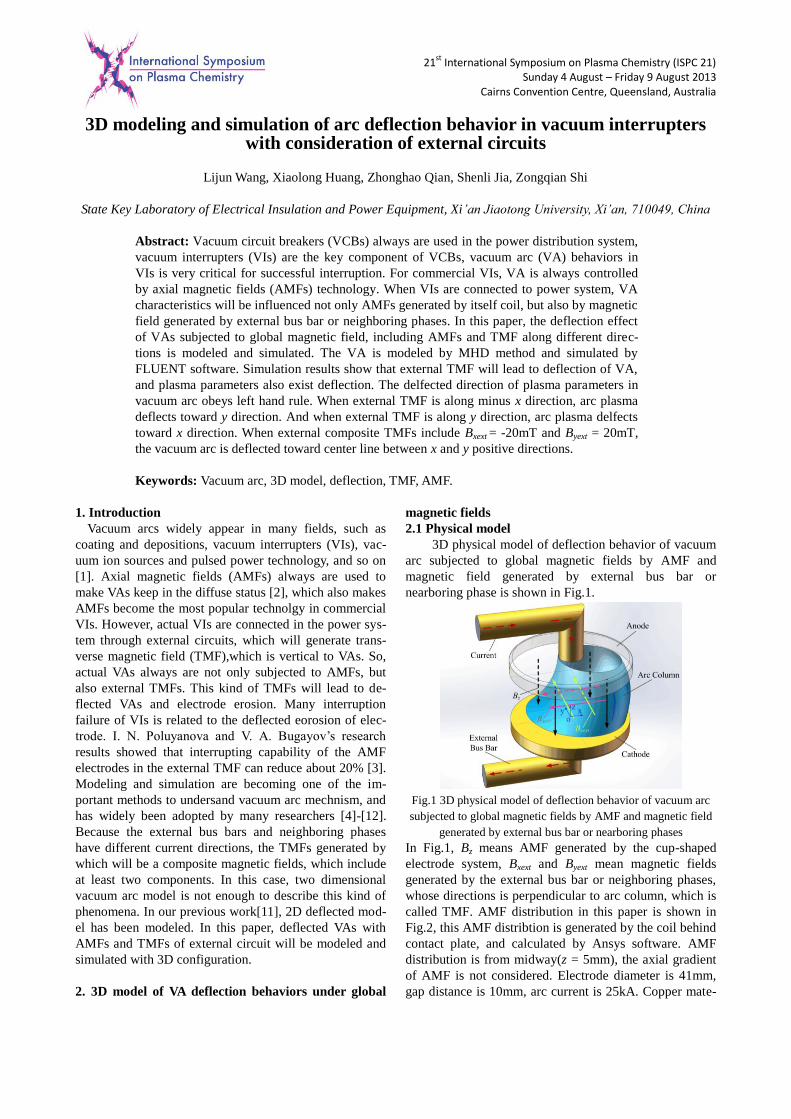
3D physical model of deflection behavior of vacuum
arc subjected to global magnetic fields by AMF and
magnetic field generated by external bus bar or
nearboring phase is shown in Fig.1.
Fig.1 3D physical model of deflection behavior of vacuum arc
subjected to global magnetic fields by AMF and magnetic field
generated by external bus bar or nearboring phases
In Fig.1, Bz means AMF generated by the cup-shaped
electrode system, Bxext and Byext mean magnetic fields
generated by the external bus bar or neighboring phases,
whose directions is perpendicular to arc column, which is
called TMF. AMF distribution in this paper is shown in
Fig.2, this AMF distribtion is generated by the coil behind
contact plate, and calculated by Ansys software. AMF
distribution is from midway(z = 5mm), the axial gradient
of AMF is not considered. Electrode diameter is 41mm,
gap distance is 10mm, arc current is 25kA. Copper mate-
21st
International Symposium on Plasma Chemistry (ISPC 21) Sunday 4 August – Friday 9 August 2013
Cairns Convention Centre, Queensland, Australia
rial is selected in the simulation. In the simulation, exter-
nal TMFs include two components, y direction and –x
direction. External TMFs are considered as unifrom dis-
tribution in arc column.
Fig.2 AMF distribution between anode and cathode (z = 5mm)
2.2 Mathematical model
Based on two-fluid theory and Maxwell equations,
the mathematical model of VA subjected to global mag-
netic field can be obtained:
0i yi x i z
n un u n u
x y z (1)
( )
( )
x x xi i x y z y z z y yext
i i e ei x
u u um n u u u j B j B B
x y z
n kT n kT
x x
(2)
( )
( )
y y y
i i x y z z x xext x z
i i e ei y
u u um n u u u j B B j B
x y z
n kT n kT
y y
(3)
( ) ( )
( )
z z zi i x y z x y yext y x xext
i i e ei z
u u um n u u u j B B j B B
x y z
n kT n kT
z z
(4)
( ( )) ( ) ( )
3( )
i i i i i i i i
e e ei ee i T e e
i
u m n E p T u Zen u E
km n n eT T u j g n k T
m
(5)
2 2 2
3( ( )) ( )
2
3( )
ee e e e e e
x y ze e eie i radiation
i
kTv n m E p j T
e
j j jkm nT T P
m
(6)
( )ej en u v (7)
0
1( ) ( )
( )
x x y yext y x xext
z x xext x z
B v B B v B By
v B B v Bz
(8)
0
1( )
( ) ( )
y y z z y yext
x y yext y x xext
B v B v B Bz
v B B v B Bx
(9)
0
0
0
1( )
1( )
1( )
y zx
xzy
yxz
B Bj
z y
BBj
x z
BBj
y x
(10)
Here, ni, ne are ion and electron number density, respec-
tively. ux, uy, and uz are ion velocities along x, y, and z
directions, respectively. vx, vy, and vz are electron veloci-
ties along x, y, and z directions, respectively. mi is the
copper ion mass, jx, jy, and jz are current density along x, y,
and z directions, respectively. Bx, By, and Bz are magnetic
fields along x, y, and z directions, respectively,which are
generated by AMFs electrode system and vacuum arc.
Bxext, Byext, are external magnetic fields along x and y di-
rections, respectively, which are generated by external bus
bar and neighboring phases. k is Boltzmann constant, Ti
and Te are ion and electron temperature. pi and pe are ion
and electron pressure; ki and ke are ion and electron ther-
mal conductivity. μ0 is vacuum permittivity. μi is ion vis-
cosity coefficient. Ei, Ee are total energy of ion and elec-
tron, respectively. u is ion velocity vector; and νei is
electron-ion collision frequency. v is electron velocity
vector; σ is electrical conductivity; gT is a coefficient. is
current density vector; e is electron charge. i is viscos-
ity stress tensor. Pradiation means plasma radiation, in this
paper, we consider vacuum arc radiation by net emmision
coefficient (NEC) method.
3. Simulation results and discussions
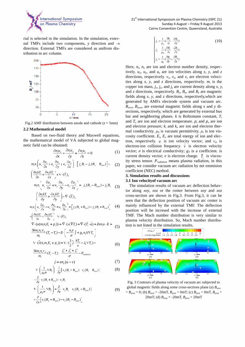
3.1 Ion velocityof vacuum arc
The simulation results of vacuum arc deflection behav-
ior along xoy, xoz or the center between xoy and xoz
cross-section are shown in Fig.3. From Fig.3, it can be
seen that the deflection position of vacuum arc center is
mainly influenced by the external TMF. The deflection
position will be incresed with the increase of external
TMF. The Mach number distribution is very similar to
plasma velocity distribution. So, Mach number distribu-
tion is not listed in the simulation results.
Fig. 3 Contours of plasma velocity of vacuum arc subjected to
global magnetic fields along some cross-sections plane (a) Bxext
= Byext = 0; (b) Bxext = -20mT, Byext = 0mT; (c) Bxext = 0mT, Byext =
20mT; (d) Bxext = -20mT, Byext = 20mT

21st
International Symposium on Plasma Chemistry (ISPC 21) Sunday 4 August – Friday 9 August 2013
Cairns Convention Centre, Queensland, Australia
Fig. 4 Contours of plasma velocity of vacuum arc subjected to
global magnetic fields on z = 5mm plane (a) Bxext = Byext = 0; (b)
Bxext = -20mT, Byext = 0mT; (c) Bxext = 0mT, Byext = 20mT; (d)
Bxext = -20mT, Byext = 20mT
3.2 Plasma pressure
Plasma pressure distribution along xoy, xoz or the center
between xoy and xoz cross-section are shown in Fig.5.
The plasma pressure distribution along z = 5mm plane is
shown in Fig.6. From Fig.5 and Fig.6, it can be seen that
the vacuum arc plasma will be deflected by the Ampere
force generated by the action of TMF arc current. From
Fig.6. (b), it can be seen that when TMF along negative
direction of x Bxext exists, the arc center will be deflected
along positive direction of y. In Fig.6. (c), it can be seen
that when TMF along positive direction of y Byext exists,
the arc center will be deflected along positive direction of
x. When the two TMFs with the same intensity (20mT)
are acted on vacuum arc, the arc center will move toward
the center between xoy and xoz cross-section, that is to
say, the angle between x axis and deflection center is 45
degree. If the TMF intensity along x and y direction is
different, this angle should be changed.
Fig. 5 Contours of plasma pressure of vacuum arc subjected to
global magnetic fields along some cross-sections plane (a) Bxext
= Byext = 0; (b) Bxext = -20mT, Byext = 0mT; (c) Bxext = 0mT, Byext =
20mT; (d) Bxext = -20mT, Byext = 20mT
Fig. 6 Plasma pressure contours of vacuum arc subjected to
global magnetic fields on z = 5mm plane (a) Bxext = Byext = 0; (b)
Bxext = -20mT, Byext = 0mT; (c) Bxext = 0mT, Byext = 20mT; (d)
Bxext = -20mT, Byext = 20mT
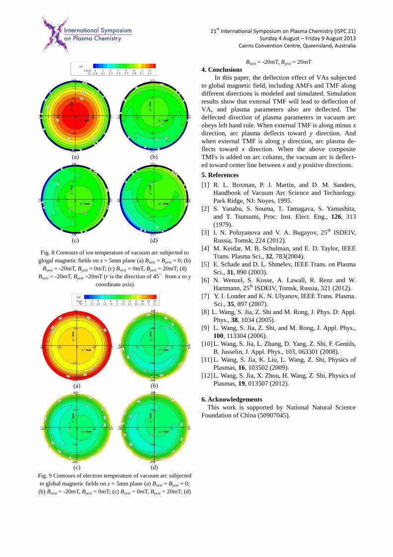
3.3 Ion and electron temperature
Ion temperature along xoy, xoz or the center between
xoy and xoz cross-section are shown in Fig.7. The ion and
electron temperature distribution along z = 5mm plane are
shown in Fig.8 and Fig.9, respectively. In Fig.7, (a), TMF
is not considered, also, in this case, arc radiation is not
considered in the model, that is why the ion temperature
in (a) is higher than (b),(c) and (d). Also, it can be seen
that when external TMF is added on arc column, ion and
electron temperature also are deflected.
Fig. 7 Contours of ion temperature of vacuum arc subjected to
global magnetic fields along some cross-sections plane (a) Bxext
= Byext = 0; (b) Bxext = -20mT, Byext = 0mT; (c) Bxext = 0mT, Byext =
20mT; (d) Bxext = -20mT, Byext = 20mT
21st
International Symposium on Plasma Chemistry (ISPC 21) Sunday 4 August – Friday 9 August 2013
Cairns Convention Centre, Queensland, Australia
Fig. 8 Contours of ion temperature of vacuum arc subjected to
glogal magnetic fields on z = 5mm plane (a) Bxext = Byext = 0; (b)
Bxext = -20mT, Byext = 0mT; (c) Bxext = 0mT, Byext = 20mT; (d)
Bxext = -20mT, Byext =20mT (r is the direction of 45°from x to y
coordinate axis)
Fig. 9 Contours of electron temperature of vacuum arc subjected
to global magnetic fields on z = 5mm plane (a) Bxext = Byext = 0;
(b) Bxext = -20mT, Byext = 0mT; (c) Bxext = 0mT, Byext = 20mT; (d)
Bxext = -20mT, Byext = 20mT
4. Conclusions
In this paper, the deflection effect of VAs subjected
to global magnetic field, including AMFs and TMF along
different directions is modeled and simulated. Simulation
results show that external TMF will lead to deflection of
VA, and plasma parameters also are deflected. The
delfected direction of plasma parameters in vacuum arc
obeys left hand rule. When external TMF is along minus x
direction, arc plasma deflects toward y direction. And
when external TMF is along y direction, arc plasma de-
flects toward x direction. When the above composite
TMFs is added on arc column, the vacuum arc is deflect-
ed toward center line between x and y positive directions.
5. References
[1] R. L. Boxman, P. J. Martin, and D. M. Sanders,
Handbook of Vacuum Arc Science and Technology.
Park Ridge, NJ: Noyes, 1995.
[2] S. Yanabu, S. Souma, T. Tamagava, S. Yamashita,
and T. Tsutsumi, Proc. Inst. Elect. Eng., 126, 313
(1979).
[3] I. N. Poluyanova and V. A. Bugayov, 25th
ISDEIV,
Russia, Tomsk, 224 (2012).
[4] M. Keidar, M. B. Schulman, and E. D. Taylor, IEEE
Trans. Plasma Sci., 32, 783(2004).
[5] E. Schade and D. L. Shmelev, IEEE Trans. on Plasma
Sci., 31, 890 (2003).
[6] N. Wenzel, S. Kosse, A. Lawall, R. Renz and W.
Hartmann, 25th
ISDEIV, Tomsk, Russia, 321 (2012).
[7] Y. I. Londer and K. N. Ulyanov, IEEE Trans. Plasma.
Sci., 35, 897 (2007).
[8] L. Wang, S. Jia, Z. Shi and M. Rong, J. Phys. D: Appl.
Phys., 38, 1034 (2005).
[9] L. Wang, S. Jia, Z. Shi, and M. Rong, J. Appl. Phys.,
100, 113304 (2006).
[10] L. Wang, S. Jia, L. Zhang, D. Yang, Z. Shi, F. Gentils,
B. Jusselin, J. Appl. Phys., 103, 063301 (2008).
[11] L. Wang, S. Jia, K. Liu, L. Wang, Z. Shi, Physics of
Plasmas, 16, 103502 (2009).
[12] L. Wang, S. Jia, X. Zhou, H. Wang, Z. Shi, Physics of
Plasmas, 19, 013507 (2012).
6. Acknowledgements
This work is supported by National Natural Science
Foundation of China (50907045).