3D Bioprinting of complex channels Effects of material, … · 3D Bioprinting of complex...
14
3D bioprinting of complex channels : effects of material, orientation, geometry, and cell embedding Wüst, S.; Müller, R.; Hofmann, S. Published in: Journal of Biomedical Materials Research, Part A DOI: 10.1002/jbm.a.35393 Published: 01/01/2015 Document Version Publisher’s PDF, also known as Version of Record (includes final page, issue and volume numbers) Please check the document version of this publication: • A submitted manuscript is the author's version of the article upon submission and before peer-review. There can be important differences between the submitted version and the official published version of record. People interested in the research are advised to contact the author for the final version of the publication, or visit the DOI to the publisher's website. • The final author version and the galley proof are versions of the publication after peer review. • The final published version features the final layout of the paper including the volume, issue and page numbers. Link to publication Citation for published version (APA): Wüst, S., Müller, R., & Hofmann, S. (2015). 3D bioprinting of complex channels : effects of material, orientation, geometry, and cell embedding. Journal of Biomedical Materials Research, Part A, 103(8), 2558-2570. DOI: 10.1002/jbm.a.35393 General rights Copyright and moral rights for the publications made accessible in the public portal are retained by the authors and/or other copyright owners and it is a condition of accessing publications that users recognise and abide by the legal requirements associated with these rights. • Users may download and print one copy of any publication from the public portal for the purpose of private study or research. • You may not further distribute the material or use it for any profit-making activity or commercial gain • You may freely distribute the URL identifying the publication in the public portal ? Take down policy If you believe that this document breaches copyright please contact us providing details, and we will remove access to the work immediately and investigate your claim. Download date: 06. Sep. 2018
Transcript of 3D Bioprinting of complex channels Effects of material, … · 3D Bioprinting of complex...

3D bioprinting of complex channels : effects of material,orientation, geometry, and cell embeddingWüst, S.; Müller, R.; Hofmann, S.
Published in:Journal of Biomedical Materials Research, Part A
DOI:10.1002/jbm.a.35393
Published: 01/01/2015
Document VersionPublisher’s PDF, also known as Version of Record (includes final page, issue and volume numbers)
Please check the document version of this publication:
• A submitted manuscript is the author's version of the article upon submission and before peer-review. There can be important differencesbetween the submitted version and the official published version of record. People interested in the research are advised to contact theauthor for the final version of the publication, or visit the DOI to the publisher's website.• The final author version and the galley proof are versions of the publication after peer review.• The final published version features the final layout of the paper including the volume, issue and page numbers.
Link to publication
Citation for published version (APA):Wüst, S., Müller, R., & Hofmann, S. (2015). 3D bioprinting of complex channels : effects of material, orientation,geometry, and cell embedding. Journal of Biomedical Materials Research, Part A, 103(8), 2558-2570. DOI:10.1002/jbm.a.35393
General rightsCopyright and moral rights for the publications made accessible in the public portal are retained by the authors and/or other copyright ownersand it is a condition of accessing publications that users recognise and abide by the legal requirements associated with these rights.
• Users may download and print one copy of any publication from the public portal for the purpose of private study or research. • You may not further distribute the material or use it for any profit-making activity or commercial gain • You may freely distribute the URL identifying the publication in the public portal ?
Take down policyIf you believe that this document breaches copyright please contact us providing details, and we will remove access to the work immediatelyand investigate your claim.
Download date: 06. Sep. 2018

3D Bioprinting of complex channels—Effects of material, orientation,geometry, and cell embedding
Silke W€ust,1 Ralph M€uller,1 Sandra Hofmann1,2,3*1Department of Health Sciences and Technology, Institute for Biomechanics, ETH Zurich, Zurich, 8093, Switzerland2Department of Biomedical Engineering, Eindhoven University of Technology, P.O. Box 513, Eindhoven, MB 5600, The
Netherlands3Department of Biomedical Engineering, Institute for Complex Molecular Systems, Eindhoven University of Technology, P.O.
Box 513, Eindhoven, MB 5600, The Netherlands
Received 28 August 2014; revised 19 November 2014; accepted 11 December 2014
Published online 00 Month 2014 in Wiley Online Library (wileyonlinelibrary.com). DOI: 10.1002/jbmm.a.35393
Abstract: Creating filled or hollow channels within 3D tissues
has become increasingly important in tissue engineering.
Channels can serve as vasculature enhancing medium perfu-
sion or as conduits for nerve regeneration. The 3D biofabrica-
tion seems to be a promising method to generate these
structures within 3D constructs layer-by-layer. In this study,
geometry and interface of bioprinted channels were investi-
gated with micro-computed tomography and fluorescent
imaging. In filament printing, size and shape of printed chan-
nels are influenced by their orientation, which was analyzed
by printing horizontally and vertically aligned channels, and
by the ink, which was evaluated by comparing channels
printed with an alginate-gelatin hydrogel or with an emul-
sion. The influence of geometry and cell-embedding in the
hydrogel on feature size and shape was investigated by print-
ing more complex channels. The generation of hollow chan-
nels, induced through leaching of a support phase, was
monitored over time. Horizontally aligned channels provided
163 smaller cross-sectional areas than channels in vertical
orientation. The smallest feature size of hydrogel filaments
was twice as large compared to emulsion filaments. Feature
size and shape depended on the geometry but did not alter
when living cells were embedded. With that knowledge,
channels can be consciously tailored to the particular needs.
VC 2014 Wiley Periodicals, Inc. J Biomed Mater Res Part A: 00A:000–
000, 2014.
Key Words: filament-based 3D bioprinting, complex channels,
structure orientation, hydrogel, cell-embedding
How to cite this article: W€ust S, M€uller R, Hofmann S. 2014. 3D Bioprinting of complex channels—Effects of material, orienta-tion, geometry, and cell embedding. J Biomed Mater Res Part A 2014:00A:000–000.
INTRODUCTION
One major challenge in tissue engineering nowadays is thelack of suitable techniques to generate artificial tissues con-taining a stable channel system. Because most tissues andall organs are vascularized, hollow channels are needed forthe creation of vascular systems within engineered 3D tis-sues to guarantee homogeneous access to nutrients andoxygen, particularly for tissues of clinically relevant sizes.1
Conventional methods to generate hollow channels includepunching out a cylinder after the fabrication of a construct2
or pouring a hydrogel in a mold which contains a fixed com-ponent in shape of the desired channel structure which canbe leached afterwards.3 However, these approaches arerestricted to straight channels, which does not allow thegeneration of complex channel structures, or by an outergeometry limited to the shape of the mold.
Nerve regeneration is important to address, for example,paraplegia or quadriplegia induced by a spinal cord injury,as it is known that grafted neurons allow the formation of
new circuits or the regeneration of injured axons.4 Stablechannels filled with a stimulative environment for neuralcells can be used to guide newly forming nerves in directionand length.5 So far, nerve regeneration has been approachedwith 2D patterns6 or prefabricated hollow channels subse-quently filled with hydrogel to stimulate neurons,7 which iseither limited to 2D or deals with the same limitations forthe conventional fabrication of channels.
Biofabrication is a powerful tool to create artificial tis-sues by placing different materials and/or cells next to eachother in predefined patterns.8–10 With appropriate deposi-tion techniques and processing conditions avoiding extremetemperatures, pH values, high shear stresses, and cytotoxiccrosslinking processes, it was shown that biological materialsuch as growth factors or cells can be included in the print-ing process with acceptable bioactivity preservation or sur-vival rates. Filament-based deposition is usually the methodof choice for printing cells concomitantly with the biomate-rial due to its gentle processing conditions compared to
Correspondence to: S. Hofmann; e-mail: [email protected] grant sponsor: RMS Foundation (Bettlach, Switzerland)
VC 2014 WILEY PERIODICALS, INC. 1

droplet-based inkjet printing, where cells are exposed tohigh shear forces due to the small orifices. Constructs fabri-cated according to the desired pattern provide a basis forfurther tissue engineering with cellular self-assembly.11
Another critical aspect for 3D bioprinting is the selectionof a suitable ink.12 The biomaterial has to support cellattachment and maintain cellular functionality for prolifera-tion and/or differentiation and maturation of the requiredtissue. Specific rheological and mechanical properties of thebiomaterial are needed to provide both printability andmechanical stability to maintain construct integrity rightafter printing and during culture. The biomaterial used inthis study is an alginate-gelatin hydrogel composite, due toits cell-friendly properties and the manifold potential appli-cations ranging from tissue engineering various tissues todrug delivery a promising material for 3D bioprinting.13–15
Alginate-gelatin was for example successfully used for livertissue engineering13 and to culture smooth muscle cells andaortic valve cells in vitro.14 It can be enhanced with osteoin-ductive16 and radiopaque17 hydroxyapatite to increase cellattachment,18 for applications in bone tissue engineering18
or as contrast agent for mCT analysis.15 By printing alginate-gelatin onto a cooled surface, gelatin acts as immediate sta-bilizer and individual printed filaments keep their initialshape.15 Once the whole construct is printed alginate ischemically crosslinked with calcium ions for long-term sta-bility19 and to connect the individual filaments perma-nently.15 Then the construct can be warmed up—gelatinprobably dissolves, which has no impact on the stability, asthe stability of the construct for cell culture at 37 �C is pro-vided by alginate. Cell compatibility of the alginate-gelatin(hydroxyapatite) hydrogel composite used herein was inves-tigated in a previous study and showed no reduction in theviability of embedded cells 3 days after printing.15
The 3D bioprinters are mostly advertised based on opti-mal conditions for performance, printing resolution andrange of processable inks. The highest printing resolution canbe achieved only with very few materials providing excellentrheological properties, which are most often not the cell-compatible biomaterials indicated as processable inks.
The aim of 3D biofabrication is to enable the generationof artificial tissues containing more complex structures.Early results in printing either filled or hollow channelswere achieved,20–25 affirming the use of bioprinting to cre-ate channels. Channels filled with material and cells wereprinted within permanent bulk material, and cells inside thechannels proliferated while retaining their functionality,20
formed confluent linings21 or produced extracellularmatrix.22 Bioprinting of hollow channels within cell-free aswell as cell-containing hydrogel bulk was realized with thebulk phase crosslinked, and the channel phase, consisting ofa support material, leached after printing.23,24 On common-ality of all of these studies is that the channels were onlyprinted in one orientation and the channel shape wasmostly a cylinder. However, to create channel structures inlarger tissues, branched systems that are organized in 3Dover several printing planes are needed, and thus a combi-nation of horizontally and vertically oriented structures will
be a great enhancement. To be able to generate complexchannel systems a systematic analysis of the individual com-ponents and influences of each parameter is necessary.
This study presents the systematic investigation ofparameters influencing feature size and shape of 3Dfilament-printed channels within a 3D construct. In particu-lar, the analyzed parameters are structure orientation, theused ink, geometry of the structure and the influence ofembedded cells. The aim was to achieve the smallest possi-ble feature size for each orientation and ink. This studyshows for the first time to what extent structure orienta-tion, ink, geometry and cell-embedding can influence featuresize through a systematic analysis of the parameters. Withthis knowledge, more intricate artificial tissues containingcomplex channel systems can be designed and fabricatedwith filament-based deposition.
MATERIALS AND METHODS
Preparation of the inksLow viscosity alginate provided as alginic acid derived frombrown algae macrocystis pyrifera (Sigma–Aldrich, Buchs,Switzerland) was slowly mixed into phosphate bufferedsaline (PBS) (Medicago, Uppsala, Sweden) to a final concen-tration of 4% (w/v) and further stirred during 2 h. Gelatintype A from porcine skin (Sigma–Aldrich, Buchs, Switzerland)was dissolved in PBS in a concentration of 20% (w/v) andkept for 2 h at 60 �C to homogenize and dissolve remainingair bubbles. The alginate-PBS solution was thoroughly mixedwith the gelatin-PBS solution in a 1:1 ratio, leading to a finalconcentration of 2% (w/v) alginate and 10% (w/v) gelatin.If needed, the hydrogel precursor was additionally enhancedwith pure hydroxyapatite powder (Acros Organics, Geel, Bel-gium) in a concentration of 8% (w/v). To do so, hydroxyapa-tite was suspended at 16% (w/v) into PBS before theaddition of alginate, and subsequently proceeded asdescribed above. Hydrogel precursors for all experimentswere pasteurized at 72 �C for 1 h and subsequently cooledto 8 �C before starting the experiments.
Nivea creme (Beiersdorf AG, Hamburg, Germany), a lipo-philic water-in-oil emulsion, was used as control group. Torender the emulsion radio-opaque for mCT imaging, theemulsion was enhanced with 8% (w/v) hydroxyapatite.
For the generation of hollow channels, gelatin served assupport material. It was dissolved in PBS at 10% (w/v) andkept 2 h at 60 �C to homogenize with a subsequent pasteur-ization at 72 �C for 1 h.
3D bioprinting systemAn open-source 2-syringe Fab@Home printer Model 2 (TheNextfab Store, Albuquerque, NM) modified with a heatableprint-head, fabricated in-house was used as described previ-ously.15 All samples were printed by extruding filamentsthrough a 27 gauge plastic dispense tip (EFD Nordson, Vil-ters, Switzerland), which corresponds to an inner tip diame-ter of 200 mm, onto a glass substrate. For hydrogel printingthe material was warmed up to 40 �C, loaded into syringesand mounted on the print-head which was kept at 40 �C.The glass substrate surface was cooled to �10 �C, which
2 W€UST, M €ULLER, AND HOFMANN 3D BIOPRINTING OF COMPLEX CHANNELS

led to immediate thermal solidification of the printed mate-rial. After printing, the hydrogel constructs were crosslinkedin 2% (w/v) CaCl2 (VWR, Dietikon, Switzerland) in PBS for10 min. For printing the emulsion, the material was loadedinto syringes and printed at room temperature directly ontothe substrate; no crosslinking step was needed to providestructural stability.
Printing channels in horizontal and vertical orientationTo investigate the influence of channel orientation on fea-ture size and shape of the cross-sectional areas, horizontallyoriented channels were printed and compared to verticallyoriented printed channels. Three different channels wereanalyzed: (i) a horizontal straight channel consisting of asingle filament, (ii) a horizontal straight channel consistingof four filaments, and (iii) a vertical straight channel. Figure1 shows a schematic representation of the various investi-gated channels, split into top view of the middle printedlayer to show the channel phase [Fig. 1(A–C)], transversalview of the whole construct illustrating printing paths and
amount of printing layers per object [Fig. 1(D–F)] and trans-versal view of the final object-to-be-printed [Fig. 1(G–I)].Schematic images were created in SolidWorks 2011 (Wal-tham, MA). To visualize the channels inside the bulk, thebulk material of all constructs was enhanced with hydroxy-apatite before printing to generate phase contrast for mCTimaging.
The common printing parameter, including printingspeed, deposition rate, distance between adjacent filamentsand layer height, were adapted for each ink-printer combina-tion. The principles as used in this study to define ideal pathwidth, which is the distance between adjacent filaments, andlayer height are illustrated in Ref. 26. The printing path ofboth phases was optimized to achieve the smallest possiblechannel in each orientation. For the hydrogel precursor print-ing path speed was set to 2 mm s21, deposition rate was0.0008 mm mm21 (mm piston motion/mm travel) and alayer height of 350 mm was used. Path width was 500 mmfor horizontal channels and 1 mm for vertical channels. Theemulsion was printed with a path speed of 4 mm s21 and a
FIGURE 1. Schematic representation of the three different channels in bulk material: (A,D,G): horizontal channel consisting of a single filament;
(B,E,H): horizontal channel consisting of four filaments and (C,F,I): vertical channel. (A–C) show the third layer of the printed construct indicating
the printing path of both phases; (D–F) show the 3D objects indicating the printing path and amount printing layers per object and (G–I) show
the 3D object with the channel as second phase.
ORIGINAL ARTICLE
JOURNAL OF BIOMEDICAL MATERIALS RESEARCH A | MONTH 2014 VOL 00A, ISSUE 00 3

deposition rate of 0.002 mm mm21. Layer height was250 mm and the path width was 250 mm for horizontal chan-nels and 500 mm for vertical channels.
mCT evaluationHydrogel samples were fixed in 10% neutral buffered forma-lin (Sigma–Aldrich, Buchs, Switzerland) for 24 h at room tem-perature immediately after crosslinking. Samples werewashed in PBS and mounted in a mCT vial filled with PBS toavoid drying and the associated shrinkage of the hydrogel.Emulsion samples were mounted on their printing substrateinto the mCT vial for imaging. The emulsion could not befixed with buffered formalin due to its lipophilic characterand was handled with great caution due to its weak stability.
Imaging was performed on a mCT 40 scanner (ScancoMedical AG, Br€uttisellen, Switzerland). Isotropic nominalresolution was 16 mm, energy of the X-ray tube was set to45 kVp and the intensity was 177 mA. Integration time was300 ms and a frame averaging of 2 was used. The resultingimages were processed with a constrained Gaussian filterwith a filter width of 0.8 and a filter support of 1. Hydrogelsamples measured in PBS were segmented with a thresholdof 58 mg HA ccm21 and the emulsion samples measured inair were segmented with a threshold of 21 mg HA ccm21,which were visually identified as best thresholds to separatethe two phases. Morphometric analysis was performedbased on parameters used for human bone biopsy analysisto assess bone volume, respectively channel volume in thisstudy, within a defined volume of interest (VOI).27,28
Analysis of channel cross-sectionsCross-sectional areas of theoretical channels were calculatedbased on the printing parameters path width and layerheight. Cross-sectional area of printed samples was eval-uated by mCT image analysis. Parameters used to describethe various channels in horizontal and vertical orientationare illustrated in Figure 2. Theoretical minimum distancedmin,t indicates the smallest possible printable distancebetween two adjacent filaments and theoretical feature size
st describes the width respectively height of the smallestpossible feature size of the channel cross-section. The cross-sections of horizontal channels lie in the xz plane whichleads to an area derived from st,x and st,z; cross-sections ofvertical channels lie in the xy plane leading to an areaderived from st,x and st,y, respectively.
Theoretical area At was calculated from the minimal the-oretical feature size in the two directions of the cross-section with the assumption that printed filaments fill therectangle between adjacent filaments and adjacent layersbelow and above:
At ¼ st;1 3st;2 (1)
Printed channel volume Vp, was obtained evaluating mCTdata with morphometric analysis.28 Area of the printed sam-ples Ap was calculated dividing Vp over the length l of thechannel:
Ap ¼ Vp 4l (2)
For hydrogel samples Vp over a length of l5 5.6 mmwas used for horizontal channels and l5 1.76 mm for verti-cal channels; for emulsion samples l5 4.8 mm was used forhorizontal channels consisting of a single filament,l55.6 mm for horizontal channels consisting of four fila-ments and l5 0.48 mm for vertical channels. The lengthswere determined visually according to the longest possibleintact channel volumes of n5 5 samples depending on therespective setup. Theoretical areas of the different channelswere compared to areas calculated from the printed andimaged channels.
Printing more complex channelsA total of five structures with different channel geometrieswere generated to investigate the influence of the geometryon the smallest possible feature size and shape of the chan-nel. The selected geometries represented channels in theshapes of L, T, S, U, and X, respectively, and contained
FIGURE 2. Parameters for geometrical analysis. Theoretical minimum distance dmin,t indicates the smallest printable distance between two adja-
cent strands and theoretical feature size st indicates the width of the smallest possible feature size of the channel cross-section. Theoretical area
At from channel cross-section is calculated from theoretical feature size with the assumption that printed strands fill the rectangle between adja-
cent strands and adjacent layers below and above.
4 W€UST, M €ULLER, AND HOFMANN 3D BIOPRINTING OF COMPLEX CHANNELS

straight segments, different rectangular elements and inter-sections with connecting channels. The hydrogel constructsconsisted all of five layers, the channels were oriented hori-zontally and located in the third printing layer. The printingscripts were individually written and the distance betweenadjacent filaments was adapted between 500 mm and 1 mmaccording to the pathway with respect to the curvatureswithin the geometry. Hydrogel compositions, printingparameter, the printing process, crosslinking and imagingwere the same as for printing straight hydrogel channels(Preparation of the inks, 3D bioprinting system, and Print-ing channels in horizontal and vertical orientation sections).Image processing was performed with a filter width of 8and a filter support of 8 for the Gaussian filter and sampleswere segmented with a threshold of 56 mg HA ccm21. Vol-ume of the printed channels was analyzed as in mCT evalua-tion section and compared to the theoretical channelvolume calculated from the channel length multiplied withAt (Analysis of channel cross-sections section) within thesame volume of interest. The evaluated VOI for all channelstructures was 6.5 3 5.5 3 1.75 mm3.
Influence of cell-embedding on feature size and shapeFor the printing of cell-containing constructs with morecomplex channels, alginate-gelatin hydrogel precursor wasenhanced with cells in both phases. To provide aseptic con-ditions for the experiment, the printer was cleaned with70% ethanol and moved into a biological safety cabinet(NU-440–600, NuAire, Plymouth, MN). Human mesenchymalstem cells (hMSCs) in sixth passage (P6) with the propertiesdescribed in Ref. 29 were labeled with CellTrackerTM GreenCMFDA for the bulk phase and with CellTrackerTM RedCMTPX for the channel phase (both CellTrackerTM from LifeTechnologies, Ltd, Zug, Switzerland). For the labeling solu-tion, both CellTrackerTM were dissolved in anhydrous dime-thylsulfoxide (DMSO) (Fluka-Chemie AG, Buchs,Switzerland), respectively at a concentration of 10 mM andsubsequently mixed with Dulbecco’s modified Eagle’smedium (DMEM) (Invitrogen Basel, Switzerland) to achieveworking solutions of 25 mM. Per 10 million cells 500 mL of25 mM working solution was used. Cells were incubated inthe CellTrackerTM working solutions for 30 min followed byan incubation in control media consisting of DMEM with10% fetal bovine serum (FBS), and 1% antibiotic/antimy-cotic solution (all obtained from Invitrogen, Basel, Switzer-land) for another 30 min. Labeled cells were thoroughlymixed into 40 �C-tempered hydrogel precursors at a concen-tration of 10 million cells/mL precursor with a spatula.Each labeled solution was filled in one of the two syringesand mounted in the print-head. The same structures as inPrinting more complex channels section were printed andcrosslinked as described in 3D bioprinting system section.Control medium was additionally supplemented with 0.25%(w/v) CaCl2 to maintain the structural integrity of the con-structs during over-night incubation.
To assess the influence of cell-embedding on feature sizeand shape, the same geometries were printed with hydrogelalone. For this control group, the alginate-gelatin hydrogel
precursor was labeled with fluorescein 5(6)-isothiocyanate(FITC) in the bulk phase and the hydrogel precursor for thechannel phase was labeled with tetramethylrhodamine iso-thiocyanate (TRITC) (both from Sigma Aldrich, Buchs, Swit-zerland). FITC as well as TRITC were dissolved inanhydrous DMSO at a concentration of 5 mg mL21 by mix-ing the solutions for 1 h on a plate-shaker protected fromlight. To stain alginate-gelatin with FITC, 5 mL of the FITC-DMSO solution was added per ml hydrogel precursor; tostain alginate-gelatin with TRITC, 10 mL of the TRITC-DMSOsolution per ml hydrogel precursor was added. The fluores-cent working solutions were mixed into the hydrogel pre-cursors at 40 �C with a spatula. Samples were printed andcrosslinked equally to the cell-containing samples.
Samples from both groups were imaged alike in bottomview and lateral view with an inverted microscope (OlympusIX51, Volketswil, Switzerland) with a 23 objective. For the lat-eral view samples were sectioned into 1-mm thick slices. Cell-TrackerTM Green as well as FITC stained hydrogel wasvisualized with the FITC filter (wavelength 530 nm, bandwidth30 nm), CellTrackerTM Red and TRITC stained hydrogel wasdetected with the TRITC filter (wavelength 590 nm, bandwidth34 nm). Background noise of the images was removed and theimage contrast was enhanced in the microscope software“cellSens Standard” by adapting the signal-to-light intensityrange of the RGB channels in the histogram. Intensity of theimages from the hydrogel-only group taken with the TRITC fil-ter was reduced to a single intensity which varied between[139, 139] and [246, 246], depending on the image and itsrespective focus during imaging. The images from both chan-nels were combined in the microscope software.
Generation of hollow channelsThe direct generation of hollow channels within a hydrogelbulk is difficult due to the missing initial construct stabilitywhen bridging hollow structures with a hydrogel. A more ela-borated approach is to fill channels during printing with asupport material which is leached afterwards. Size of theprinted channels, filled with gelatin, was varied between one,four and nine filaments, organized in matrices of 1, 2 3 2,and 3 3 3, like in Figure 1(D,G) and Figure 1(E,H). Tostrengthen the investigation of gelatin leaching depending onchannel size, the channel composed of 3 3 3 filaments wasadditionally added. With a path width of 500 mm and a layerheight of 350 mm, the expected sizes of the channels were500 3 350 mm2, 1000 3 700 mm2, and 1500 3 1050 mm2,respectively. The surrounding bulk material was constantlyset to two layers of filaments in all directions for all con-structs. In analogy to Influence of cell-embedding on featuresize and shape section, alginate-gelatin hydrogel precursorwas stained with FITC and gelatin was stained with TRITCbefore printing. Samples were printed and crosslinked asdescribed in 3D bioprinting system section. A piece of 5 mmlength was cut out of the 20 mm long samples with a razorblade from the middle of the samples for longitudinal imagingand a 1 mm thick disc for cross-sectional imaging. Sampleswere moved into eight-well nuncTM Lab-TekTM ChamberedCoverglass (Thermo Fisher Scientific, Wohlen, Switzerland)
ORIGINAL ARTICLE
JOURNAL OF BIOMEDICAL MATERIALS RESEARCH A | MONTH 2014 VOL 00A, ISSUE 00 5

filled with 500 mL PBS which additionally contained 0.25%(w/v) CaCl2 to maintain the structural integrity of the con-structs. Gelatin starts leaching once heated up above roomtemperature. The constructs were kept on ice until the firstimaging time point was taken and moved to 37 �C to initializegelatin leaching immediately after. Gelatin leaching was moni-tored with an inverted microscope and a 23 objective during3 h with imaging time points after 30, 90, and 180 min toassess the formation of hollow channels. Before and aftereach imaging time point the well was carefully moved to gen-erate medium fluctuation to distribute the leached gelatin inthe well reducing the signal of the leached gelatin close to theobject for imaging and to enhance gelatin leaching. Thesignal-to-light intensity ranges of the images were adjusted asdescribed in Influence of cell-embedding on feature size andshape section.
Statistical analysisAll quantitative values are reported as means6 standarddeviation with n55 samples per group. To compare groups,statistical analysis of variance (ANOVA) was performedusing PASW Statistics 18 (SPSS, Chicago, IL), applying anunivariate ANOVA with Bonferroni Post Hoc test. p values<0.05 were considered statistically significant and p< 0.01highly statistically significant.
RESULTS
Printing channels in horizontal and vertical orientationFilament-based 3D bioprinting requires at least two con-nected points in one printing layer to generate material out-put. To reduce a channel to the least possible amount ofpoints based on that condition, the channel in vertical orien-tation was defined with four points in a 2 3 2 matrix. To beable to compare vertical- versus horizontal channel orienta-tion, a horizontal channel consisting of four filaments, whichcorresponds to the four points in the vertical orientation, wasadded. It was observed during ink deposition that materialaccumulation occurred when printing curvatures. For straightchannels in horizontal orientation curvatures were locatedonly at the end of the construct and did not affect the area ofinterest [Fig. 1(A,B)]. In contrast, when printing straight chan-nels in vertical orientation, where curvatures were present inthe construct [Fig. 1(C)], material accumulation occurred inthe middle of the geometry. This additional material deposi-tion had to be compensated by providing enhanced lateralspace. The distance between adjacent filaments had to bedoubled for printing the vertical channels compared to thehorizontal channels to be able to print a decent cylindricalgeometry. Representative images of printed channels ana-lyzed by mCT are illustrated in Figure 3 as negatives for amore informative presentation—implying that the channelphase is visible in the image instead of the hydroxyapatite-enhanced radiopaque bulk phase. The outer dimensions ofthe constructs are indicated with the box.
Channel cross-sectional areaCross-sectional areas of the theoretical and the printedchannels were evaluated; the parameters used for calcula-
tions are illustrated in Figure 2. For hydrogel precursorprinting dmin,t 5 500 mm was used for horizontal channelsand dmin,t 5 1 mm was used for vertical channels. Theoreti-cal feature size for a horizontal channel consisting of a sin-gle filament was st,x 5500 mm and st,z 5 350 mmconsidering a layer height of 350 mm, and for the horizon-tal channel consisting of four filaments it was st,x 5 1 mmand st,z 5 700 mm, respectively. For a vertical channel thecalculation of the theoretical feature size led to st,x 52 mmand st,y 5 2 mm. Theoretical cross-sectional area of thehydrogel channels calculated with Eq. (1) wasAt 50.18 mm2 for a horizontal channel consisting of a sin-gle filament, At 50.7 mm2 for a horizontal channel consist-ing of four filaments and At 5 4 mm2 for a vertical channel(Table I).
The emulsion was printed with dmin,t 5250 mm for hori-zontal channels and dmin,t 5500 mm for vertical channelswith a layer height of 250 mm; leading to st,x 5 250 mm andst,z 5 250 mm for a horizontal channel consisting of a singlefilament, st,x 5500 mm and st,z 5 500 mm for a horizontalchannel consisting of four filaments and st,x 51 mm andst,y 5 1 mm for a vertical channel, respectively. Theoreticalcross-sectional area of the emulsion channels calculatedwith Eq. (1) was At 5 0.06 mm2 for a horizontal channelconsisting of a single filament, At 50.25 mm2 for a horizon-tal channel consisting of four filaments and At 5 1 mm2 fora vertical channel (Table I).
The printed samples were analyzed with mCT analysisregarding channel volumes. The average area over a certainlength was calculated with Eq. (2) (Table I). For the printedhydrogel samples, channel cross-sectional areas wereAp 50.36 0.1 mm2 for horizontal channels consisting of asingle filament, Ap 5 1.060.2 mm2 for horizontal channelsconsisting of four filaments and Ap 5 6.860.9 mm2 for ver-tical channels. Channel cross-sectional areas of printedemulsion samples were Ap 5 0.160.0 mm2 for horizontalchannels consisting of a single filament, Ap 5 0.260.0 mm2
for horizontal channels consisting of four filaments andAp 50.96 0.3 mm2 for vertical channels.
To compare printed to theoretical cross-sectional area ofthe different channels, the ratios of Ap/At were calculated(Table I). For the hydrogel groups the average Ap was largerthan At. Ap was only in the range of At in the group withhorizontal channels consisting of a single filament. For thehydrogel channels no statistical difference was detectedbetween Ap of horizontal channels consisting of a single fila-ment compared to horizontal channels consisting of four fil-aments. Channel orientation had a statistically significanteffect at p<0.01 in Ap between the vertical channels com-pared to the horizontal channels. For channels printed withemulsion the average Ap was smaller than At. Ap was only inthe range of At in the group with vertical channels. For theemulsion channels statistically significant differences of Apwere consistent with the hydrogel group, with a statisticallysignificant difference at p<0.01 between the vertical chan-nels and the horizontal channels, respectively. Plots in Fig-ure 4 illustrate Ap (column) and At (dashed line) of thehydrogel and emulsion channels in the various orientations.
6 W€UST, M €ULLER, AND HOFMANN 3D BIOPRINTING OF COMPLEX CHANNELS

Structure orientation effectsTo assess the influence of structure orientation on featuresize, At and Ap were compared between the different chan-nels and their deviation factors At/At and Ap/Ap summarizedin Figure 5(A). At of the vertical hydrogel channel was 233
larger than At of the horizontal channel consisting of a singlefilament and 63 larger than At of the horizontal channel con-sisting of four filaments. For the emulsion, At was 163 and43 larger, respectively. For printed hydrogel constructs, Ap ofvertical channels was on average 233 larger compared to Apof horizontal channels consisting of a single filament and onaverage 73 larger compared to Ap of horizontal channelsconsisting of four filaments. For printed emulsion constructs,Ap was on average 733 and 63 larger, respectively.
Regarding the influence on the shape, printed verticalchannels revealed a more circular channel cross-sectioncompared to the horizontal channels, which resulted in dif-ferently distinct flattened filaments (Fig. 3).
Material effectsTo assess the influence of the ink on feature size, At and Apwere compared between the different materials used andAt/At and Ap/Ap summarized in Figure 5(B). In theory, thecross-sectional area of the horizontal hydrogel channel con-sisting of a single filament is 33 larger compared to thehorizontal emulsion channel consisting of a single filament.In reality, Ap of horizontal hydrogel channels consisting of asingle filament was on average 243 larger compared to thecorresponding emulsion channels. For horizontal hydrogelchannels consisting of four filaments the areas were theoret-ically 33 larger and practically 73 larger on average com-pared to the corresponding emulsion channels. For thevertical channels, the area of the hydrogel channel is theo-retically 43 larger than the area of the emulsion channeland resulted in an average of a 73 larger area of printedhydrogel channels compared to emulsion channels.
Regarding the influence on the shape, individual fila-ments of the hydrogel did not keep the round shape andflattened—leading to the path width of 500 mm and layerheight of 350 mm. Adjacent filaments merged and one con-nected channel was achieved. Single filaments of the emul-sion were structurally more stable and the round shape ofthe initial filament flattened only slightly during deposition.Adjacent filaments of the emulsion did not fully merge [Fig.3(B)]. Hydrogel channels in vertical orientation revealed a
TABLE I. Theoretical Minimum Distance dmin,t, Theoretical
Feature Size st, Theoretical Area At, Printed Area Ap and the
Ratio of Printed to Theoretical Area At/Ap of Channels
Printed With Hydrogel and the Emulsion for Horizontal and
Vertical Channel Orientation with n 5 5
Material Orientationdmin,t
(mm)st
(mm)At
(mm2)Ap
(mm2)
Hydrogel Horizontal 0.5 0.5 0.18 0.3 6 0.14Horizontal 4x 0.5 1 0.7 1.04 6 0.2Vertical 1 2 4 6.81 6 0.94
Emulsion Horizontal 0.25 0.25 0.06 0.01 6 0.01Horizontal 4x 0.25 0.5 0.25 0.15 6 0.03Vertical 0.5 1 1 0.91 6 0.28
Horizontal represents the horizontal channels consisting of a single
filament, horizontal 43 the horizontal channels consisting of four fila-
ments and vertical the channels in vertical orientation.
FIGURE 3. Negative images of printed channels in bulk material. The left column shows representative samples printed with hydrogel and the
right column shows representative samples printed with emulsion. Row (A) shows the horizontal channels consisting of a single filament in
bulk material, row (B) the horizontal channels consisting of four filaments in bulk material and row (C) the vertical channels in bulk material.
ORIGINAL ARTICLE
JOURNAL OF BIOMEDICAL MATERIALS RESEARCH A | MONTH 2014 VOL 00A, ISSUE 00 7

circular channel cross-section but an inhomogeneous chan-nel shape with visible influences from the printing layers,while the cross-section of emulsion channels in vertical ori-entation was rather square but a homogeneous channelshape in the longitudinal axis was achieved. The connectionbetween adjacent hydrogel filaments was strengthened withthe chemical crosslinking after printing and the printedstructure was much stronger compared to the emulsion.
More complex channel geometriesMore complex channel geometries in the shape of L, T, S, U,and X were printed within bulk material. Schematics of theprinting paths which were used to generate the differentchannels and the bulk phase are illustrated in Figure 6(A).Qualitative analysis performed by mCT [Fig. 6(B)] showedthe feasibility of printing the different geometries consistingof various rectangular elements and intersections with con-necting channels. Material accumulation in the channelstructures was visible at curvatures. For sequential rectan-gular elements near each other, such as at the S-shape, thematerial accumulation was even further enhanced and had
to be compensated with a locally larger feature size forprinting; in contrast to multiple rectangular elements withlarger distance, such as the U-shape. The additional materialgot dragged into the curvature of rectangular elementsnearby. Additionally, a difference in layer height was noticedat the intersection of connecting channels for all samples.The ratios between printed channel volumes quantitativelyanalyzed with mCT and theoretical channel volumes werebetween 1.3 and 2.4 (Table II), implying that the printedchannels all had larger volumes compared to the theoreticalchannels.
Influence of cell-embedding on feature size and shapeTo assess the influence of cell-embedding, fluorescentlylabeled cells with a different color for each phase wereembedded into the hydrogel and compared to an equalsetup without cells in which the two hydrogel phases werefluorescently stained. The geometries used in More complexchannel geometries section could be printed with cell-containing bioink with the same feature size as the purehydrogel and allowed channel fabrication in equal size [Fig.
FIGURE 4. Theoretical (At) and printed (Ap) channel cross-sectional area of (A) the hydrogel and (B) the emulsion. At is illustrated with a dashed
line; Ap is illustrated as column and indicated as means 6 standard deviation with n 5 5. *p< 0.05, **p< 0.01. The values correspond to At and
Ap from Table I.
FIGURE 5. Structure orientation effects (A) and material effects (B) on theoretical and printed channels made of hydrogel or emulsion in horizon-
tal and vertical orientation. Effects are indicated with deviation factors At/At and Ap/Ap. For example was At of the hydrogel channel in vertical
orientation 233 larger than At of the hydrogel channel consisting of a single filament in horizontal orientation. Horizontal represents horizontally
oriented channels consisting of a single filament, horizontal 43 horizontally oriented channels consisting of four filaments and vertical channels
in vertical orientation.
8 W€UST, M €ULLER, AND HOFMANN 3D BIOPRINTING OF COMPLEX CHANNELS

7(A,B)]. Comparing the representative images of the cell-containing group to the hydrogel-only group [Fig. 7(A–D)],the shape of curvatures and intersections were more impre-cise for the cell-containing structures compared to the non-cellular structures, whereas no difference in the shape ofthe straight parts of the structures was detected. Cells werehomogeneously distributed in the material and stayedwithin their phase after printing and crosslinking.
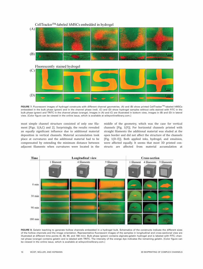
Generation of hollow channelsThe creation of hollow channels within a bulk-material con-sisting of alginate-gelatin hydrogel was achieved by usinggelatin as support material for the channel phase duringprinting and leaching the gelatin subsequently once the con-struct was printed. Figure 8 illustrates schematics of theinvestigated geometries as well as fluorescent images of theprinted samples in longitudinal and cross-sectional view.The representative fluorescent images indicate the leachingof gelatin during 3 h at 37 �C, with the amount of remaininggelatin correlating with the orange TRITC signal. Gelatin
leaching took place continuously in all samples starting atthe interface between channel and bulk material. After 3 honly a weak TRITC signal was detected in all groups, indi-cating that the support material was almost completelyleached from the smallest to the largest channel size. Thebulk material remained stable revealing an intact hollowchannel after gelatin leaching.
DISCUSSION
The 3D bioprinting promises high potential for the fabrica-tion of more complex filled or hollow stable channels whichcannot be generated with conventional methods. To improvechannel fabrication with filament-based deposition, the maininterests of this study were to determine the influence ofstructure orientation and ink on the smallest possible fea-ture size and shape of the channels, the influence of theprinted geometry and embedded cells. The findings showthat these influences significantly affect the resulting chan-nels, and will serve as basis for the design of larger con-structs containing channels for filament-based deposition.More sophisticated 3D channels filled with a stimulativeenvironment will help to overcome certain limitations innerve regeneration5 or to generate hollow channels for tis-sue engineering larger constructs to improve nutrients andoxygen supply.
As expected, structure orientation did have a remarkableinfluence on filament-based printed objects. We assumedthat the minimum of two points in one plane needed toinduce the material outflow is the main cause for larger ver-tically aligned structures, since these points were orthogonalto the channel axis—in contrast to horizontal structureswhere the two points were on the channel axis and the
FIGURE 6. (A) schematics of different channel geometries embedded in the bulk material. (B) negative mCT images of the 3D printed hydrogel
constructs. The outer dimensions of the investigated volume of interest are indicated with the box.
TABLE II. Volume Analysis of the More Complex Channel
Structures Printed With Hydrogel (n 5 1)
Geometry Vp (mm3) Vt (mm3) Vp/Vt (L)
L-shape 1.7 1.3 1.3T-shape 2.2 1.6 1.3S-shape 4.1 2.1 1.9U-shape 2.9 1.7 1.7X-shape 4.6 1.9 2.4
Channel volume of printed geometries Vp, theoretical channel vol-
ume Vt within the same VOI, and the ratio of printed to theoretical
channel volume Vp/Vt are compared.
ORIGINAL ARTICLE
JOURNAL OF BIOMEDICAL MATERIALS RESEARCH A | MONTH 2014 VOL 00A, ISSUE 00 9
most simple channel structure consisted of only one fila-ment [Figs. 1(A,C) and 2]. Surprisingly, the results revealedan equally significant influence due to additional materialdeposition in vertical channels. Material accumulation tookplace at curvatures and the additional material had to becompensated by extending the minimum distance betweenadjacent filaments when curvatures were located in the
middle of the geometry, which was the case for verticalchannels [Fig. 1(F)]. For horizontal channels printed withstraight filaments the additional material was eluded at theopen border and did not affect the structure of the channels[Fig. 1(D–E)]. Both applied inks, hydrogel, and emulsion,were affected equally. It seems that most 3D printed con-structs are affected from material accumulation at
FIGURE 7. Fluorescent images of hydrogel constructs with different channel geometries. (A) and (B) show printed CellTrackerTM-labeled hMSCs
embedded in the bulk phase (green) and in the channel phase (red). (C) and (D) show hydrogel samples without cells stained with FITC in the
bulk phase (green) and TRITC in the channel phase (orange). Images in (A) and (C) are illustrated in bottom view, images in (B) and (D) in lateral
view. [Color figure can be viewed in the online issue, which is available at wileyonlinelibrary.com.]
FIGURE 8. Gelatin leaching to generate hollow channels embedded in a hydrogel bulk. Schematics of the constructs indicate the different sizes
of the hollow channels and the image orientation. Representative fluorescent images of the samples in longitudinal and cross-sectional view are
illustrated at different time points (0, 30, 90, and 180 min). Bulk phase (green) contains alginate-gelatin hydrogel and is labeled with FITC; chan-
nel phase (orange) contains gelatin and is labeled with TRITC. The intensity of the orange dye indicates the remaining gelatin. [Color figure can
be viewed in the online issue, which is available at wileyonlinelibrary.com.]
10 W €UST, M €ULLER, AND HOFMANN 3D BIOPRINTING OF COMPLEX CHANNELS

curvatures, for example the printed agar30 or hydroxyapatitescaffold.31,32 However in the majority of the studies thegeometry itself is not affected since it is printed withstraight filaments20–22 and the additional material can beeluded at the open border. Material accumulation is notalways equally distinctive and is sometimes less visible,such as the curved hydrogel channel in Ref. 25 which isembedded in a hydrogel bulk with the same color. Materialaccumulation could probably be reduced by a locally fasterprinting speed or lower deposition rate at curvatures. Theoption to change one of these two parameters during thefabrication of a construct, however, was not provided byFab@Home. Differences in filament shape of the differentinks are clearly visible in Figure 3. We assume that theshape of a filament is related to material characteristicssuch as viscosity, rheological behavior and surface tensionbut also to the printing- and solidification process. One pre-vious study assigned the effect of different fiber diametersand scaffold architectures of various hydrogels to their gela-tion rate,33 another study reported the influence of the inkon path width and length.26 Path width and layer heightreflected the shape of the filament cross-section, with awidth-to-height ratio of 1:1 for round filaments such as theemulsion and a larger width-to-height ratio for oval cross-sections as it was the case for the hydrogel used in thisstudy. The larger width-to-height ratio of deposited fila-ments is often found in hydrogel printing. For example PEG-DA used in Ref. 26 was printed with 800 mm path widthand 600 mm layer height and pure alginate was imple-mented with 800 mm path width and 190 mm layer height.23
However, the shape of a printed filament is not related tothe mechanical stability of the whole construct. The emul-sion filament almost kept its shape as it was deposited fromthe printer without crosslinking procedure, but the printedconstruct completely lacked mechanical stability; it col-lapsed at the slightest contact. The hydrogel in contrast flat-tened during deposition but revealed strong mechanicalintegrity after crosslinking.
The used ink had a significant influence on the smallestpossible distance between adjacent filaments and thus thefeature size to print a decent geometry (Table I). In case thevalue of the theoretical area was within the range of theassociated areas from printed channels the printing parame-ters were properly chosen (Fig. 4). This was only achievedfor one group per ink. To define printing parameters whichexactly fit geometries in different orientations is challenging.The Ap/At ratios indicate whether the theoretical area isunderestimated (Ap/At>1), or overestimated (Ap/At< 1).The overestimated area is also visible as cavities within theprinted object, which can be seen in the emulsion channelin horizontal orientation consisting of four filaments in Fig-ure 3(B).
Other groups using bioinks with comparable propertiesto the hydrogel used in this study reached similar or evenlarger minimal feature sizes with a filament-based deposi-tion; they printed alginate-gelatin with 800 mm pathwidth,14 alginate with 800 mm,23 hyaluronan with 500 mm34
or PEG-DA with 800 mm.26 Smaller feature sizes were
achieved by printing pure gelatin (7% (w/v)) with a pathwidth of 400 mm24 or pure alginate (2 mg mL21) with 300mm.33 Both inks were less viscous compared to the bioinkcontaining 10% (w/v) gelatin plus 2% (w/v) alginate inthis study, which probably allowed printing smaller features.The gelatin concentration in Ref. 24 was sufficient for itsapplication as temporary support material; the pure alginateprinted in a CaCl2-bath to generate 3D constructs resultedin a limited stacking of multiple layers.33 We observed in aprevious study that alginate printed directly in a CaCl2-bathcannot bind between layers.15 In our hydrogel, gelatininduced immediate construct stability allowing for the algi-nate to be crosslinked only after fabrication, which enabledbinding between layers and the generation of a mechanicalinteger 3D construct. The inclusion of hydroxyapatiteenabled visualization of the printed construct with mCT. Thisfavorable combination was a compromise which resulted ina slightly larger minimal feature size. With a lower resolu-tion an overall larger size of the 3D construct can beachieved, as printing resolution is directly related to thesize of the biofabricated sample.8 Time is restricted if livingcells are included in the printing process: A lengthy expo-sure of cells to the high stress level during processing canbe detrimental, and hydrogels desiccate over time.
A higher printing resolution and greater scaffold stabil-ity can be achieved with different methods. For printingscaffold material only, a larger variety of materials, cross-linking and/or post-treatment procedures can be appliedsince potential cytotoxic substances can be removed afterscaffold fabrication, would allow for an ink with more favor-able printing characteristics.35 In that case cells can beseeded afterwards; however, this excludes the advantage of atargeted cell placement within the 3D construct given by thecell-based 3D bioprinting. Smaller feature sizes could also beachieved for example with inkjet printing, which was used toprint fibrin fibers containing endothelial cells with 93 mmfiber diameter.21 During inkjet printing cells are exposed tohigher shear forces induced by the small fluid volumes whichmay cause damage to cells.36 Inkjet printing requires less vis-cous substrate solutions and the final constructs result in anoverall smaller size due to limited construct stability espe-cially in 3D—examples using inkjet printing in combinationwith hydrogels are therefore rather limited.35 With the focuson a combined cell-biomaterial deposition to generate 3D tis-sues, more requirements on the bioink and the printing pro-cess have to be fulfilled, which implies the compromise inresolution. However there is large potential to furtherdevelop this approach, especially from the materials technol-ogy side. The associated crosslinking process to achieve sta-ble constructs has to be considered since it strongly affectsgelation time and resulting strength of the hydrogel, mayinduce clogging of the printing tip during fabrication andoften entails unwanted cytotoxic side-products. Printed aga-rose filaments, for example, fused under their own weightdue to the slow gelation rate.33 A chitosan scaffold cross-linked with sodium hydroxide- ethanol was biocompatiblewhen seeded with cells afterwards37; however, the cross-linker is detrimental to cells and cannot be used for cell-
ORIGINAL ARTICLE
JOURNAL OF BIOMEDICAL MATERIALS RESEARCH A | MONTH 2014 VOL 00A, ISSUE 00 11

embedding. Also 2-photon-polymerization, which allowedPEG-DA scaffold fabrication in nm resolution, is not suitablefor cell embedding since residual material from the usedphotoinitiators seemed to diffuse out of the polymer andresulted in impaired cell viability.38
The geometry did have an influence on feature size andshape of the printed channels, which is no surprise regardingthe findings about material accumulation at curvatures in themiddle of an object. Additional material which was depositedat sequential rectangular elements in short distance to eachother such as the S-shape had to be compensated with a locallylarger path width in the printing script resulting in a locallylarger feature size in the final construct. However, this did notaffect the ratios of printed to theoretical channel volumes inthe VOI of the complex channels, which were within the rangeof hydrogel channels consisting of a single filament in horizon-tal orientation (Tables I and II). Anyhow, a trend toward ahigher ratio of printed to theoretical channel volume wasdetected of geometries with more rectangular elements andintersections such as the S- and X-shape, which coincides withthe observations from the qualitative image analysis regardingmaterial accumulation and shape deformation. For the investi-gation of more complex channels a horizontal orientation waschosen due to the smaller possible feature sizes; nerve regen-eration was for example addressed in the range between 100and 600 mm.7 The smaller branched channels could be con-nected, if needed, with larger channels in vertical orientation.
The embedding of cells in the bioink is a great advantageof 3D biofabrication allowing the generation of elaboratedcell-based 3D tissue constructs. Multiple cell types can beprinted in specific locations overcoming limitations of ran-dom cell distribution and uncontrolled ingrowth due to cellseeding by hand.39 However, the addition of cells to thehydrogel precursor altered the concentration of the bioink—and as we showed, the ink can significantly affect the printedfilaments and thus the shape of the 3D construct (Materialeffects section). The more complex channel structures wereused to compare printed hydrogel channels with [Fig. 7(A,B)]and without cells [Fig. 7(C,D)] to assess various facets ofprinting with multiple straight and rectangular elements aswell as crossings. Embedding of cells did not influence mate-rial behavior during printing and led to the same feature sizeas obtained for hydrogel-only samples. The slightly less pre-cise shape of the cell-containing hydrogel channels and aslightly weaker construct can be related to the reducedhydrogel concentration, which might have resulted in lessspots for the crosslinker to attach. As it has been shown, cel-lular self-assembly is a powerful mechanism of engineeringtissue, as the example of a self-assembled branched structurebuilt of fibroblast spheroids has shown.11 Therefore, theslightly changed ink properties are not expected to have anegative influence on tissue engineering. Printing channelscontaining living cells shows great potential for tissue recon-struction especially when cells in adjacent phases stay intheir location but the phases remain physically connectedafter crosslinking, which was the case in this study.
Hollow channels could for example be important fornutrient and oxygen transport as well as the removal of
waste products. The successful generation of hollow channelsrequires a setup which allows the removal of the supportstructure in the channel phase as well as a stable 3D bulkconstruct during and after processing. Gelatin was almostcompletely leached within only 3 h for all printed channelsindependent of their size (Fig. 8). From the cross-sectionalimages it could be observed that gelatin leaching started atthe interface of the support structure, with the gelatin in themiddle of the support phase being only leached after 3 h.The generation of channels in an alginate-gelatin bulk mate-rial with gelatin as support structure showed advantagescompared to other approaches. The smallest hollow channelgenerated via alginate leaching in gelatin methacrylamide-gellan hydrogel had a diameter of 4 mm,23 compared to thesmallest hollow channel of 500 3 350 mm2 presented herein.Smaller vessels with 300 mm in diameter were achieved withscaffold-free cell printing,11 but the lack of mechanical integ-rity, which is usually provided by the hydrogel, limits thistechnique to small constructs.
In this study the generation of filled and hollow chan-nels within 3D constructs made by filament-based 3D bio-printing was investigated using the smallest possible featuresize for every setup. Parameters examined included thosepotentially influencing feature size and shape of the chan-nels, in particular structure orientation, ink, geometry, andcell-embedding.
CONCLUSION
A systematic investigation revealed a significant influence ofstructure orientation, geometry and ink on the smallest pos-sible feature size and shape of filament-based printed 3Dchannels. The influence on feature size could mainly beattributed to the need of connecting two points in oneprinting plane in filament printing and to material accumu-lation at curvatures of the printing path which affected ver-tically oriented channels. Material accumulation occurredalso at more complex geometries with multiple rectangularelements nearby or crossings and is therefore important toconsider when designing tissue constructs and the corre-sponding printing path. On the basis of these results wesuggest designing complex channels with rectangular ele-ments with minimum three path width distance to limit theincrease in feature size by avoiding excessive material accu-mulation. Because of the significant influence of the ink onfeature size and shape of the channels the material shouldbe analyzed prior to 3D tissue printing. Adding cells to thehydrogel did not alter feature size and shape of the chan-nels. Hollow channels could be generated in different sizeswithin the same time. For alginate-gelatin (-hydroxyapatite),the smallest printed channel was 500 3 350 mm2 for filledchannels as well as for hollow channels using gelatin assupport material. The 3D constructs with anisotropic struc-tures could be organized to produce the best possible out-come. For the design of larger constructs with a branchedchannel-system it would imply larger channels orientatedvertically and smaller branched channels oriented horizon-tally. The cell-hydrogel system presented in this study pro-vides a solid basis for the generation of filled and hollow
12 W €UST, M €ULLER, AND HOFMANN 3D BIOPRINTING OF COMPLEX CHANNELS

3D channels for various tissues with the potential to be fur-ther developed to address applications such as nerve gener-ation or vasculature.
ACKNOWLEDGMENTS
The authors acknowledge Marie E. Godla, Michael Vogt, andVitaly Koren from the Institute for Biomechanics, ETH Zurichfor preliminary experiments.
REFERENCES1. Khademhosseini A, Vacanti JP, Langer R. Progress in tissue engi-
neering. Sci Am 2009;300:64–71.
2. Bian L, Angione SL, Ng KW, Lima EG, Williams DY, Mao DQ,
Ateshian GA, Hung CT. Influence of decreasing nutrient path
length on the development of engineered cartilage. Osteoarthritis
Cartilage 2009;17:677–685.
3. Huang G, Wang S, He X, Zhang X, Lu TJ, Xu F. Helical spring
template fabrication of cell-laden microfluidic hydrogels for tissue
engineering. Biotechnol Bioeng 2013;110:980–989.
4. Thuret S, Moon LDF, Gage FH. Therapeutic interventions after spi-
nal cord injury. Nat Rev Neurosci 2006;7:628–643.
5. Steed MB, Mukhatyar V, Valmikinathan C, Bellamkonda RV.
Advances in bioengineered conduits for peripheral nerve regener-
ation. Atlas Oral Maxillofac Surg Clin 2011;19:119–130.
6. Zhu N, Li MG, Guan YJ, Schreyer DJ, Chen XB. Effects of laminin
blended with chitosan on axon guidance on patterned substrates.
Biofabrication 2010;2:045002
7. Wang A, Ao Q, Cao W, Yu M, He Q, Kong L, Zhang L, Gong Y,
Zhang X. Porous chitosan tubular scaffolds with knitted outer
wall and controllable inner structure for nerve tissue engineering.
J Biomed Mater Res A 2006;79A:36–46.
8. W€ust S, M€uller R, Hofmann S. Controlled positioning of cells in
biomaterials—Approaches towards 3D tissue printing. J Funct
Biomater 2011;2:119–154.
9. Fedorovich NE, Alblas J, de Wijn JR, Hennink WE, Verbout AJ,
Dhert WJ. Hydrogels as extracellular matrices for skeletal tissue
engineering: State-of-the-art and novel application in organ print-
ing. Tissue Eng 2007;13:1905–1925.
10. Mironov V, Trusk T, Kasyanov V, Little S, Swaja R, Markwald R.
Biofabrication: a 21st century manufacturing paradigm. Biofabri-
cation 2009;1:022001
11. Norotte C, Marga FS, Niklason LE, Forgacs G. Scaffold-free vascu-
lar tissue engineering using bioprinting. Biomaterials 2009;30:
5910–5917.
12. Derby B. Printing and prototyping of tissues and scaffolds. Sci-
ence 2012;338:921–926.
13. Balakrishnan B, Jayakrishnan A. Self-cross-linking biopolymers as
injectable in situ forming biodegradable scaffolds. Biomaterials
2005;26:3941–3951.
14. Duan B, Hockaday LA, Kang KH, Butcher JT. 3D bioprinting of
heterogeneous aortic valve conduits with alginate/gelatin hydro-
gels. J Biomed Mater Res A 2013; 101:1255–1264. A
15. W€ust S, Godla ME, M€uller R, Hofmann S. Tunable hydrogel com-
posite with two-step processing in combination with innovative
hardware upgrade for cell-based three-dimensional bioprinting.
Acta Biomater 2014;10:630–640.
16. Barradas AM, Yuan H, van Blitterswijk CA, Habibovic P. Osteoin-
ductive biomaterials: Current knowledge of properties, experi-
mental models and biological mechanisms. Eur Cell Mater 2011;
21:407–429.
17. Bohner M, van Lenthe GH, Gr€unenfelder S, Hirsiger W, Evison R,
M€uller R. Synthesis and characterization of porous [beta]-trical-
cium phosphate blocks. Biomaterials 2005;26:6099–6105.
18. Lin H-R, Yeh Y-J. Porous alginate/hydroxyapatite composite scaf-
folds for bone tissue engineering: Preparation, characterization,
and in vitro studies. J Biomed Mater Res B Appl Biomater 2004;
71B:52–65.
19. Zimmermann H, Shirley S, Zimmermann U. Alginate-based
encapsulation of cells: Past, present, and future. Curr Diabet Rep
2007;7:314–320.
20. Li S, Xiong Z, Wang X, Yan Y, Liu H, Zhang R. Direct fabrication
of a hybrid cell/hydrogel construct by a Double-nozzle assembling
Technology. J Bioactive Comp Polym 2009;24:249–265.
21. Cui X, Boland T. Human microvasculature fabrication using ther-
mal inkjet printing technology. Biomaterials 2009;30:6221–7.
22. Skardal A, Zhang J, McCoard L, Xu X, Oottamasathien S,
Prestwich GD. Photocrosslinkable hyaluronan-gelatin hydrogels
for Two-step bioprinting. Tissue Eng A 2010;16:2675–2685.
23. Visser J, Peters B, Burger TJ, Boomstra J, Dhert WJA, Melchels
FPW, Malda J. Biofabrication of multi-material anatomically
shaped tissue constructs. Biofabrication 2013;5:035007.
24. Lee W, Lee V, Polio S, Keegan P, Lee J-H, Fischer K, Park J-K, Yoo
S-S. On-demand three-dimensional freeform fabrication of multi-
layered hydrogel scaffold with fluidic channels. Biotechnol Bioeng
2010;105:1178–1186.
25. Zhang Y, Yu Y, Chen H, Ozbolat IT. Characterization of printable
cellular micro-fluidic channels for tissue engineering. Biofabrica-
tion 2013;5:025004.
26. Kang KH, Hockaday LA, Butcher JT. Quantitative optimization of
solid freeform deposition of aqueous hydrogels. Biofabrication
2013;5:035001.
27. Hildebr T, Laib A, M€uller R, Dequeker J, R€uegsegger P. Direct
three-dimensional morphometric analysis of human cancellous
bone: Microstructural data from spine, femur, iliac crest, and cal-
caneus. J Bone Miner Res 1999;14:1167–1174.
28. Stauber M, M€uller R. Micro-computed tomography: A method for
the non-destructive evaluation of the three-dimensional structure
of biological specimens. Methods Mol Biol 2008;455:273–292.
29. Hofmann S, Hagenm€uller H, Koch AM, M€uller R, Vunjak-
Novakovic G, Kaplan DL, Merkle HP, Meinel L. Control of in vitro
tissue-engineered bone-like structures using human mesenchy-
mal stem cells and porous silk scaffolds. Biomaterials 2007;28:
1152–1162.
30. Landers R, H€ubner U, Schmelzeisen R, M€ulhaupt R. Rapid proto-
typing of scaffolds derived from thermoreversible hydrogels and
tailored for applications in tissue engineering. Biomaterials, 2002;
23:4437–4447.
31. Carvalho C, Landers R, Mulhaupt R, Hubner U, Schmelzeisen R.
Fabrication of soft and hard biocompatible scaffolds using 3D-
BioplottingTM. In 2nd, International Conference on Advanced
Research and Rapid Prototyping; Virtual Modeling and Rapid
Manufacturing. Leiria, Portugal: Taylor and Francis; 2005.
32. Bartolo PJS, Almeida H, Laoui T. Rapid prototyping and manufac-
turing for tissue engineering scaffolds. Int J Comput Appl Technol
2009;36:1–9.
33. Fedorovich NE, De Wijn JR, Verbout AJ, Alblas J, Dhert WJ.
Three-dimensional fiber deposition of cell-laden, viable, patterned
constructs for bone tissue printing. Tissue Eng A 2008;14:127–
133.
34. Skardal A, Zhang J, Prestwich GD. Bioprinting vessel-like con-
structs using hyaluronan hydrogels crosslinked with tetrahedral
polyethylene glycol tetracrylates. Biomaterials 2010;31:6173–6181.
35. Billiet T, Vandenhaute M, Schelfhout J, Van Vlierberghe S,
Dubruel P. A review of trends and limitations in hydrogel-rapid
prototyping for tissue engineering. Biomaterials 2012;33:6020–
6041.
36. Ringeisen BR, Othon CM, Barron JA, Young D, Spargo BJ. Jet-
based methods to print living cells. Biotechnol J 2006;1:930–948.
37. Ang TH, Sultana FSA, Hutmacher DW, Wong YS, Fuh JYH, Mo
XM, Loh HT, Burdet E, Teoh SH. Fabrication of 3D chitosan-
hydroxyapatite scaffolds using a robotic dispensing system.
Mater Sci Eng C 2002;20:35–42.
38. Ovsianikov A, Malinauskas M, Schlie S, Chichkov B, Gittard S,
Narayan R, L€obler M, Sternberg K, Schmitz KP, Haverich A.
Three-dimensional laser micro- and nano-structuring of acrylated
poly(ethylene glycol) materials and evaluation of their cytoxicity
for tissue engineering applications. Acta Biomater 2011;7:967–
974.
39. Thimm BW, W€ust S, Hofmann S, Hagenm€uller H, M€uller R. Initial
cell pre-cultivation can maximize ECM mineralization by human
mesenchymal stem cells on silk fibroin scaffolds. Acta Biomater
2011;7:2218–2228.
ORIGINAL ARTICLE
JOURNAL OF BIOMEDICAL MATERIALS RESEARCH A | MONTH 2014 VOL 00A, ISSUE 00 13