3A0233F - Air-Powered Ram, Instructions-Parts, English€¦ · Instructions-Parts Air-Powered Ram...
28
Instructions-Parts Air-Powered Ram For transferring or dispensing a non-heated bulk supply of sealants, adhesives, or other medium to high viscosity fluids. Replaces rams for Hydra-Mate ™ , Precision Dose, 8900 Proportioner, 1:1 Extruders, and robotic interface rams. For professional use only. Not for use in explosive atmospheres. D200 3 inch dual post 200 liter (55 gallon) 150 psi (1.0 MPa, 10 bar) Maximum Air Inlet Pressure See page 3 for model information and maximum working pressure. Important Safety Instructions Read all warnings and instructions in this manual. Save these instructions. r_257435_3a0233_1c 257435 Model Shown 3A0233F EN
Transcript of 3A0233F - Air-Powered Ram, Instructions-Parts, English€¦ · Instructions-Parts Air-Powered Ram...

Instructions-Parts
Air-Powered Ram
For transferring or dispensing a non-heated bulk supply of sealants, adhesives, or other medium to high viscosity fluids. Replaces rams for Hydra-Mate™, Precision Dose, 8900 Proportioner, 1:1 Extruders, and robotic interface rams. For professional use only.
Not for use in explosive atmospheres.
D200 3 inch dual post200 liter (55 gallon)150 psi (1.0 MPa, 10 bar) Maximum Air Inlet Pressure
See page 3 for model information and maximum working pressure.
Important Safety InstructionsRead all warnings and instructions in this manual. Save these instructions.
r_257435_3a0233_1c
257435 Model Shown
3A0233FEN

Related Manuals
2 3A0233F
Related ManualsComponent Manuals in U.S. English:
Manual Description
310726 1:1 Extruder, Operation
308930 Hydra-Mate™ Variable Ratio Proportioner309790 8900 Proportioner
307982 Power-Flo® Displacement Pump
307049 Bulldog® Air Motor
309348 King® Air Motor
307043 Monark® Air Motor312374 Air Controls Instructions-Parts406681 Platen Cover Kit

Ram Models
3A0233F 3
Ram ModelsThis table lists ram models that replace rams included with Graco bulk supply systems that have older style rams. Ram models without integrated air controls utilize the air controls of the compatible system.
Pump Mounting ChartThis table lists the parts necessary to mount various Graco pumps on the ram. Refer to pages 11-12 for mounting instructions. See Accessories on page 24 for parts.
For pump mounting and application information, contact your Graco distributor.
Ram Model Size Style Compatible System
Replaces Ram Platen Air Controls
257435 3 in. D200 Not specified 207279 NA Integrated air controls with pump regulator
257452 3 in. D200 Hydra-Mate systems 196079 55 gallon EPDM
NA
257453 3 in. D200 Hydra-Mate systems 196708 55 gallon neoprene
NA
24C769 3 in. D200 8900 Proportioner 232110 55 gallon EPDM
Integrated air controls without pump regulator
257461 3 in. D200 1:1 Extruder 954419 NA NA
Pump TypeRam Mounting Kit
224829Platen Mounting Kit
222776
Monark® and President® Check-Mate™ 450 Pumps
Bulldog® and Senator® Check-Mate™ 450 Pumps
King™, Bulldog®, and Senator® Check-Mate™ 800 Pumps
King™ Check-Mate™ 1000 Pumps
King™, Bulldog®, and Viscount® Check-Mate™ 2100 Pumps
King™, Bulldog®, and Senator® Power-Flo® Pumps
Monark® and President® Check-Mate™ 200 Pumps
Bulldog and King Pumps with intake housing mounting flange
Fire-Ball 300, 50:1 247335 and 247336
Fire-Ball 425, 10:1, 50:1, 75:1 247335 and 247337

Warnings
4 3A0233F
WarningsThe following warnings are for the setup, use, grounding, maintenance, and repair of this equipment. The exclama-tion point symbol alerts you to a general warning and the hazard symbol refers to procedure-specific risk. Refer back to these warnings. Additional, product-specific warnings may be found throughout the body of this manual where applicable.
WARNINGSKIN INJECTION HAZARD High-pressure fluid from gun, hose leaks, or ruptured components will pierce skin. This may look like just a cut, but it is a serious injury that can result in amputation. Get immediate surgical treatment.• Do not point gun at anyone or at any part of the body.• Do not put your hand over the fluid outlet.• Do not stop or deflect leaks with your hand, body, glove, or rag.• Follow Pressure Relief Procedure in this manual, when you stop dispensing and before cleaning,
checking, or servicing equipment.• Tighten all fluid connections before operating the equipment.• Check hoses and couplings daily. Replace worn or damaged parts immediately.
FIRE AND EXPLOSION HAZARD Flammable fumes, such as solvent and paint fumes, in work area can ignite or explode. To help prevent fire and explosion:• Use equipment only in well ventilated area.• Eliminate all ignition sources; such as pilot lights, cigarettes, portable electric lamps, and plastic drop
cloths (potential static arc). • Keep work area free of debris, including solvent, rags and gasoline.• Do not plug or unplug power cords, or turn power or light switches on or off when flammable fumes
are present.• Ground all equipment in the work area. See Grounding instructions.• Use only grounded hoses.• Hold gun firmly to side of grounded pail when triggering into pail.• If there is static sparking or you feel a shock, stop operation immediately. Do not use equipment
until you identify and correct the problem.• Keep a working fire extinguisher in the work area.
ELECTRIC SHOCK HAZARD This equipment must be grounded. Improper grounding, setup, or usage of the system can cause elec-tric shock.• Turn off and disconnect power cord before servicing equipment.• Use only grounded electrical outlets.• Use only 3-wire extension cords.• Ensure ground prongs are intact on power and extension cords.• Do not expose to rain. Store indoors.

Warnings
3A0233F 5
WARNINGMOVING PARTS HAZARDMoving parts can pinch or amputate fingers and other body parts.• Keep clear of moving parts.• Do not operate equipment with protective guards or covers removed.• Pressurized equipment can start without warning. Before checking, moving, or servicing equipment,
follow the Pressure Relief Procedure and disconnect all power sources.
SPLATTER HAZARD Hot or toxic fluid can cause serious injury if splashed in the eyes or on skin. During blow off of platen, splatter may occur. • Use minimum air pressure when removing platen from drum.
TOXIC FLUID OR FUMES HAZARD Toxic fluids or fumes can cause serious injury or death if splashed in the eyes or on skin, inhaled, or swal-lowed.• Read MSDS’s to know the specific hazards of the fluids you are using.• Store hazardous fluid in approved containers, and dispose of it according to applicable guidelines.
EQUIPMENT MISUSE HAZARD Misuse can cause death or serious injury.• Do not operate the unit when fatigued or under the influence of drugs or alcohol.• Do not exceed the maximum working pressure or temperature rating of the lowest rated system com-
ponent. See Technical Data in all equipment manuals.• Use fluids and solvents that are compatible with equipment wetted parts. See Technical Data in all
equipment manuals. Read fluid and solvent manufacturer’s warnings. For complete information about your material, request MSDS from distributor or retailer.
• Do not leave the work area while equipment is energized or under pressure. Turn off all equipment and follow the Pressure Relief Procedure in this manual when equipment is not in use.
• Check equipment daily. Repair or replace worn or damaged parts immediately with genuine manu-facturer’s replacement parts only.
• Do not alter or modify equipment.• Use equipment only for its intended purpose. Call your distributor for information.• Route hoses and cables away from traffic areas, sharp edges, moving parts, and hot surfaces.• Do not kink or over bend hoses or use hoses to pull equipment.• Keep children and animals away from work area.• Comply with all applicable safety regulations.
PERSONAL PROTECTIVE EQUIPMENTYou must wear appropriate protective equipment when operating, servicing, or when in the operating area of the equipment to help protect you from serious injury, including eye injury, inhalation of toxic fumes, burns, and hearing loss. This equipment includes but is not limited to:• Protective eyewear and hearing protection.• Respirators, protective clothing, and gloves as recommended by the fluid and solvent manufacturer.

Component Identification
6 3A0233F
Component Identification
D200 Rams
Key:A Ram AssemblyB Platen (see FIG. 3)C Integrated Air Controls (see FIG. 2)D Platen Bleed PortE Blowoff Air Supply Line (see FIG. 15)F Platen Lift RodG Main Air Line (not supplied)H Air Line Drain Valve (not supplied)J Air Filter (not supplied)K Bleed Type Air Shutoff Valve (not supplied)
FIG. 1: Typical Installation
257435 Model Shown
A
Lift Locations
B
D
C
F
G
K
J
H

Component Identification
3A0233F 7
Integrated Air ControlsThe integrated air controls include:
• Main air slider valve (AA): turns air on and off to the system. When closed, the valve relieves pres-sure downstream.
• Ram air regulator (AB): controls ram up and down pressure and blowoff pressure.
• Ram director valve (AC): controls ram direction.
• Exhaust port with muffler (AD)
• Air motor regulator (AE): controls air pressure to motor.
• Air motor slider valve (AF): turns air on and off to the air motor. When closed, the valve relieves air trapped between it and the air motor. Push the valve in to shutoff.
• Blowoff button (AG): turns air on and off to push the platen out of an empty drum.
Air Line AccessoriesSee FIG. 1.
• Air line drain valve (H)
• Air line filter (J): removes harmful dirt and moisture from compressed air supply.
• Second bleed-type air valve (K): isolates air line accessories and ram for servicing. Locate upstream from all other air line accessories.
• Air relief valve (attached to ram air regulator, not visible): automatically relieves excessive pressure.
FIG. 2. Integrated Air Controls
AA
AB
AC
AG
AD
ti10438a
AE
AF
{not included with 24C824
Component Identification
8 3A0233F
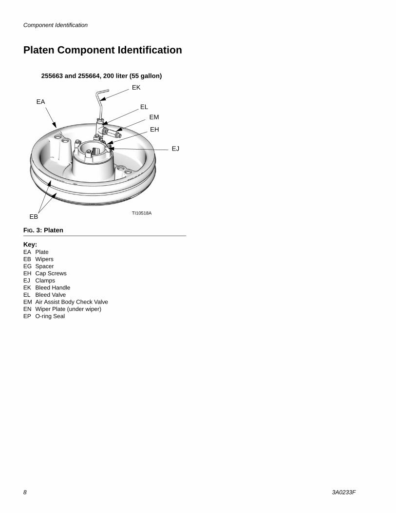
Platen Component Identification
Key:EA PlateEB WipersEG SpacerEH Cap ScrewsEJ ClampsEK Bleed HandleEL Bleed ValveEM Air Assist Body Check ValveEN Wiper Plate (under wiper)EP O-ring Seal
FIG. 3: Platen
TI10518A
255663 and 255664, 200 liter (55 gallon)
EB
EJ
EK
EL
EH
EM
EA

Installation
3A0233F 9
InstallationNOTE: Reference numbers and letters in parenthe-ses in the text refer to the callouts in the figures.
Accessories are available from Graco. Make certain all accessories are adequately sized and pressure-rated to meet the system’s requirements.
FIG. 1 is the only guide for selecting and installing sys-tem components and accessories. Contact your Graco distributor for assistance in designing a system to suit your particular needs.
Location
Attach a lifting sling at the proper lift spots. Lift off the pallet using a crane or a forklift.
Position the ram so the air controls are easily accessi-ble. Ensure that there is enough space overhead for the ram to raise fully. (See Dimensions, page 26.)
Using the holes in the ram base as a guide, drill holes for 1/2 in. (13 mm) anchors.
Ensure that the ram base is level in all directions. If nec-essary, level the base using metal shims. Secure the base to the floor using 1/2 in. (13 mm) anchors that are long enough to prevent the ram from tipping.
GroundingTrapped air can cause the pump to cycle unexpectedly, which could result in serious injury from splashing or moving parts.
Pump: use a ground wire and clamp. Loosen grounding lug locknut and washer. Insert one end of supplied ground wire into slot in lug and tighten locknut securely. Connect other end of wire to a true earth ground. See FIG. 4.
Air and fluid hoses: use only electrically conductive hoses with a maximum of 500 ft. (150 m) combined hose length to ensure grounding continuity. Check elec-trical resistance of hoses. If total resistance to ground exceeds 29 megohms, replace hose immediately.
Air compressor: follow manufacturer’s recommenda-tions.
Spray gun/dispense valve: ground through connection to a properly grounded fluid hose and pump.
Fluid supply container: follow local code.
Object being sprayed: follow local code.
Solvent pails used when flushing: follow local code. Use only conductive metal pails, placed on a grounded surface. Do not place the pail on a nonconductive sur-face, such as paper or cardboard, which interrupts grounding continuity.
To maintain grounding continuity when flushing or relieving pressure: hold metal part of the dispense valve firmly to the side of a grounded metal pail, then trigger the valve.
NOTICEAlways lift ram at proper lift locations (see FIG. 1). Do not lift in any other way. Lifting at these loca-tions allows the ram to be lifted straight up and pre-vents the ram from bumping into objects nearby.
The equipment must be grounded. Grounding reduces the risk of static and electric shock by provid-ing an escape wire for the electrical current due to static build up or in the event of a short circuit.
FIG. 4
ti8250a

Installation
10 3A0233F
Attach Drum StopsRams are shipped with drum stops in place to help posi-tion the drum on the ram. For replacement parts, order Kit 255477. The kit includes 2 each of capscrews (FA), lock washers (not shown), and drum stops (FB).
1. Locate the correct set of mounting holes on the ram base.
2. Using the capscrews (FA) and lock washers (not shown), attach the drum stops (FB) to the ram base.
FIG. 5
FAFBti10917a
FIG. 6: Ram Base
D200 and D200s Base

Installation
3A0233F 11
Mount Check-Mate 450, 800, 1000, and 2100 PumpsNOTE:
The Pump Mounting Chart on page x lists the parts necessary to mount Check-Mate 450, 800, 1000, and 2100 Pumps on this ram. Installing other pumps on the ram may require alternate parts. For information, contact your Graco distributor.
This installation requires Mounting Kit 222776 and 224829 which must be ordered separately. See Accessories on page 24.
1. Position the mounting brackets (42) so that the top of the pump will clear the support beam (4).
2. For President and Monark Check-Mate 450 Pumps only, install the mounting plate (CA) from kit 224829 onto the mounting brackets (42) using four screws (CB) and lockwashers (CC). See FIG. 7.
NOTE: The plate (CA) is oriented differently for the President than for the Monark.
3. Attach the motor to the mounting brackets (57) or mounting plate (CA) with the fasteners supplied (‡), as applicable.
4. Place the gasket (CK) from Mounting Kit 222776 on the ram plate (114). See FIG. 8. Loosen the mount-ing bracket setscrews (43), and carefully lower the pump onto the gasket and plate. Secure the pump’s intake flange (CN) to the plate with the screws (CL) and lugs (CM) included in the mounting kit.
FIG. 7
For President Pumps
For Monark Pumps
CACC
CB
CJ
CL
CA
‡CB
CC
FIG. 802938
CL
CMCN
CK
114

Installation
12 3A0233F
Mount Power-Flo, Check-Mate 200, Fire-Ball 300 and Fire-Ball 400 PumpsNOTE:
The Pump Mounting Chart on page 3 lists the parts necessary to mount Power-Flo, Check-Mate 200, Fire-Ball 300 and Fire-Ball 425 pumps on this ram. Installing other pumps on the ram may require alter-nate parts. For information, contact your Graco dis-tributor.
1. Position the mounting brackets (42) so that the top of the pump will clear the support beam (4).
2. For President, Monark Check-Mate 200, and Fire–Ball Pumps only, install the mounting plate (CA) onto the mounting brackets (42) using four screws (CB) and lockwashers (CC). See FIG. 9.
NOTE: The plate (CA) is oriented differently for the President and Fire–Ball 425 than for the Monark and Fire–Ball 300.
3. Attach the motor to the mounting brackets (42) or mounting plate (CA) with the fasteners supplied, as applicable.
NOTE: Before proceeding to step 4, install Adapter Kit 224267 for the Fire–Ball 300 pump. Install Adapter Kit 224266 for Fire–Ball 425, 50:1 and 75:1 Pump.
4. Slide the top seal plate (CG) up over the pump intake valve and push the seal (CF) onto the pump intake housing. Leave the bottom seal plate (CG) and gasket (CH) in place. See FIG. 10.
5. Loosen the mounting bracket setscrews (35), and carefully lower the pump until the intake valve is below the gasket (CH), then tighten the setscrews.
6. Push the seal (CF) down firmly against the bottom seal plate (CG).
7. Align the holes in the top seal plate with the holes in the ram plate (114). Secure tightly to the ram plate with the four screws (CD) and washers (CC).
FIG. 9
For President and Fire-Ball 425 Pumps
For Monark and Fire-Ball 300 Pumps
r_257435_3a0233_3c
CA
CC
CB
CCCB
CA
r_257435_3a0233_2c
FIG. 1002938
CF CD, CC
CG
114
CG CH
Installation
3A0233F 13
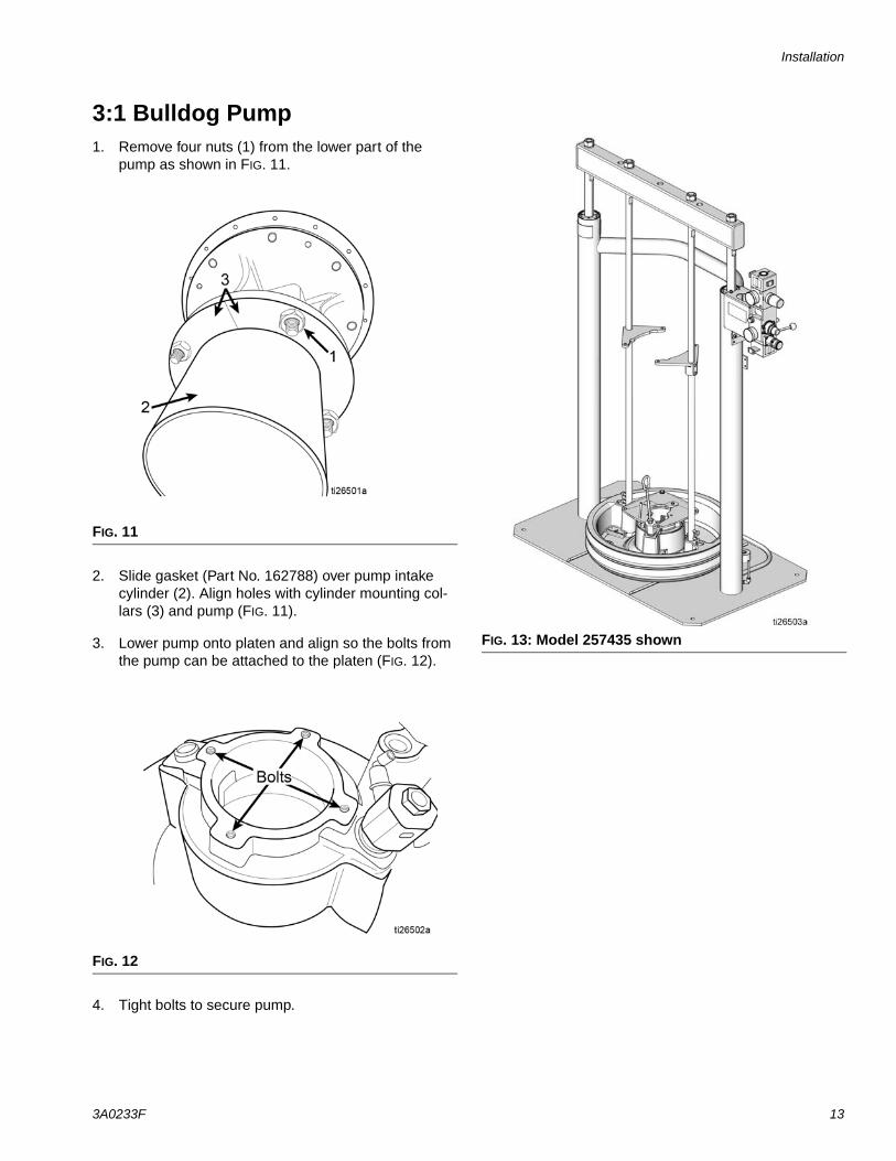
3:1 Bulldog Pump1. Remove four nuts (1) from the lower part of the
pump as shown in FIG. 11.
2. Slide gasket (Part No. 162788) over pump intake cylinder (2). Align holes with cylinder mounting col-lars (3) and pump (FIG. 11).
3. Lower pump onto platen and align so the bolts from the pump can be attached to the platen (FIG. 12).
4. Tight bolts to secure pump.
FIG. 11
FIG. 12
FIG. 13: Model 257435 shown
Operation
14 3A0233F
Operation
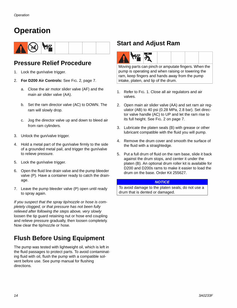
Pressure Relief Procedure1. Lock the gun/valve trigger.
2. For D200 Air Controls: See FIG. 2, page 7.
a. Close the air motor slider valve (AF) and the main air slider valve (AA).
b. Set the ram director valve (AC) to DOWN. The ram will slowly drop.
c. Jog the director valve up and down to bleed air from ram cylinders.
3. Unlock the gun/valve trigger.
4. Hold a metal part of the gun/valve firmly to the side of a grounded metal pail, and trigger the gun/valve to relieve pressure.
5. Lock the gun/valve trigger.
6. Open the fluid line drain valve and the pump bleeder valve (P). Have a container ready to catch the drain-age.
7. Leave the pump bleeder valve (P) open until ready to spray again.
If you suspect that the spray tip/nozzle or hose is com-pletely clogged, or that pressure has not been fully relieved after following the steps above, very slowly loosen the tip guard retaining nut or hose end coupling and relieve pressure gradually, then loosen completely. Now clear the tip/nozzle or hose.
Flush Before Using EquipmentThe pump was tested with lightweight oil, which is left in the fluid passages to protect parts. To avoid contaminat-ing fluid with oil, flush the pump with a compatible sol-vent before use. See pump manual for flushing directions.
Start and Adjust Ram
1. Refer to FIG. 1. Close all air regulators and air valves.
2. Open main air slider valve (AA) and set ram air reg-ulator (AB) to 40 psi (0.28 MPa, 2.8 bar). Set direc-tor valve handle (AC) to UP and let the ram rise to its full height. See FIG. 2 on page 7.
3. Lubricate the platen seals (B) with grease or other lubricant compatible with the fluid you will pump.
4. Remove the drum cover and smooth the surface of the fluid with a straightedge.
5. Put a full drum of fluid on the ram base, slide it back against the drum stops, and center it under the platen (B). An optional drum roller kit is available for D200 and D200s rams to make it easier to load the drum on the base. Order Kit 255627.
Moving parts can pinch or amputate fingers. When the pump is operating and when raising or lowering the ram, keep fingers and hands away from the pump intake, platen, and lip of the drum.
NOTICETo avoid damage to the platen seals, do not use a drum that is dented or damaged.

Operation
3A0233F 15
6. Remove bleed stick from platen bleed port (D).
7. If drum has a plastic liner, pull it over edge of drum. Secure liner with tape wrapped around circumfer-ence of drum.
8. Set the director valve (AC) to DOWN and lower the ram until fluid appears at the top of the platen bleed port (D). Adjust ram air regulator (AB) as needed. Set the director valve (AC) to neutral and close the platen bleed port (D). 2-Button Interlock: If system has this feature, press and hold both buttons to start lowering the ram. See FIG. 2, page 7.
Start and Adjust Pump1. Connect pump outlet fittings and hose (not sup-
plied).
NOTE: Be sure all components are adequately sized and pressure rated to meet the system’s require-ments.
2. Be sure the pump air valve is closed. Then set the ram air regulator (AB) to about 50 psi (0.35 MPa, 3.5 bar). Set the director valve (AC) to DOWN. Start the pump as explained in the separate pump instruction manual.
3. Keep the director valve (AC) set to DOWN while pump is operating.
NOTE: Increase air pressure to the ram if the pump does not prime properly with heavier fluids. Decrease air pressure if fluid is forced out around the top seal or platen.
Change Drums
1. Stop the pump.
a. Push in the air motor slider valve (AF) to stop the pump.
2. Raise the platen out of the drum.
a. Set ram director valve (AC) to UP to raise the platen (B) and immediately press and hold the blowoff air button (AG) until the platen (B) is completely out of drum. Use minimum amount of air pressure necessary to push the platen out of the drum.
3. Follow steps 4-8.
4. Release the blowoff air button and allow the ram to rise to its full height.
5. Remove empty drum.
6. Inspect platen and, if necessary, remove any remaining material or material build–up.
7. Place full drum on ram base.
8. Lower the ram and adjust the position of the drum relative to the platen. See Start and Adjust Ram on page 14.
FIG. 14
D
B ti10543a
Excessive air pressure in the material drum could cause the drum to rupture, causing serious injury. The platen must be free to move out of the drum. Never use drum blowoff air with a damaged drum.

Maintenance
16 3A0233F
Maintenance
Platen MaintenanceSee FIG. 15. If the platen does not come out of the pail easily when the pump is being raised, the air assist tube (F), or check valve may be plugged. A plugged valve prevents air from reaching the underside of the plate to assist in raising it from the pail.
1. Relieve pressure. Refer to parts illustration on page 24 and disassemble air assist valve as shown.
2. Clear air assist tube (F) in platen. Clean all parts of valve and reassemble.
3. Remove bleed stick (EK) from platen. Push bleed stick through bleed relieve ports to remove material residue.
Remove 55 Gallon Platen Wipers
1. To replace worn or damaged wipers (EB), raise platen up out of drum. Remove drum from base. Wipe fluid off of platen.
2. Cut top and bottom wipers with knife and remove from platen. See FIG. 16.
Reinstall 55 Gallon Platen Wipers
1. Using a wooden or plastic tool to prevent damage to the wiper (EB), clean all material from seal grooves.
2. Working from the bottom, angle one wiper (EB) over back of platen. See FIG. 17.
3. Insert wiper (EB) in top groove and run front of wiper into groove.
4. Insert second wiper (EB) in lower groove and run front of wiper into groove.
5. Lubricate outside of wiper with lubricant compatible with material being pumped. Check with material supplier.
To reduce the risk of serious injury whenever you are instructed to relieve pressure, always follow the Pres-sure Relief procedure.
FIG. 15
EG
F
r_255319_3a0233_1b
FIG. 16
FIG. 17
TI10613A
EB
TI10614A
EB
Troubleshooting
3A0233F 17
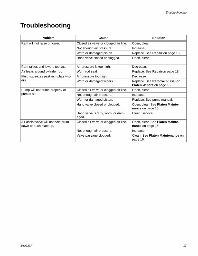
Troubleshooting
Problem Cause Solution
Ram will not raise or lower. Closed air valve or clogged air line. Open, clear.
Not enough air pressure. Increase.
Worn or damaged piston. Replace. See Repair on page 18.
Hand valve closed or clogged. Open, clear.
Ram raises and lowers too fast. Air pressure is too high. Decrease.
Air leaks around cylinder rod. Worn rod seal. Replace. See Repairon page 18.
Fluid squeezes past ram plate wip-ers.
Air pressure too high. Decrease.
Worn or damaged wipers. Replace. See Remove 55 Gallon Platen Wipers on page 16.
Pump will not prime properly or pumps air.
Closed air valve or clogged air line. Open, clear.
Not enough air pressure. Increase.
Worn or damaged piston. Replace. See pump manual.
Hand valve closed or clogged. Open, clear. See Platen Mainte-nance on page 16.
Hand valve is dirty, worn, or dam-aged.
Clean, service.
Air assist valve will not hold drum down or push plate up.
Closed air valve or clogged air line. Open, clear. See Platen Mainte-nance on page 16.
Not enough air pressure. Increase.
Valve passage clogged. Clean. See Platen Maintenance on page 16.

Repair
18 3A0233F
Repair
D200 3 in. Ram Piston Rods
Always service both cylinders at the same time. When you service the piston rod always install new o-rings in the piston rod seal and ram piston.
Disassemble Piston Rod Seal and Bearing
1. Relieve pressure.
2. Access piston rod seal and bearing.
a. Remove nuts (6) and lockwashers (5) holding the tie bar (4) to the piston rods (2n). Refer to parts illustration on page 20 or page 22.
b. Remove tie bar (4).
3. Remove retaining ring (3).
4. Remove piston rod seal and bearing.
a. Slide end cap (2a), pin (2b), o-ring (2c), and spring (2m) up off of the piston rod (2n).
b. Remove retaining ring (2k) and bearing (2j) from end cap (2a) and remove o-ring (2d).
5. Inspect parts for wear or damage. Replace as nec-essary.
NOTE: Do not reinstall end cap assembly if the ram piston (2e) needs to be removed from the piston rod. See Assemble Piston Rod Seal and Bearing instruc-tions.
Assemble Piston Rod Seal and Bearing
See FIG. 18.
1. Lubricate o-ring (2d) and bottom bearing (2j).
a. Install o-ring (2d), bottom bearing (2j), and retaining ring (2k) into end cap (2a).
b. Install new o-ring (2c) and pin (2b) on end cap (2a). Lubricate o-ring (2c) and end cap (2a).
c. Slide spring (2m) and end cap (2a) on piston rod (2n).
2. Install retaining ring (3).
3. Install tie bar (4), washers (5), and nuts (6).
To reduce the risk of serious injury whenever you are instructed to relieve pressure, always follow the Pres-sure Relief procedure. Do not use pressurized air to remove the guide sleeve or the piston.
FIG. 18: 3 in. Piston Rod Seal
TI10520A2n
2m
2k
2j
2a
2c3
2b
2d

Repair
3A0233F 19
Disassemble Ram Piston
1. Complete steps 1-4 from Disassemble Piston Rod Seal and Bearing to remove the end cap from the piston rod.
2. Carefully lay piston (2e) and rod (2n) down so piston rod will not be bent. Remove nut (2f), washer (2g), piston (2e), outer o-ring (2c), and inner o-ring (2h).
3. Inspect parts for wear or damage. Replace as nec-essary.
Assemble Ram Piston
1. Install new o-rings (2h, 2c) and lubricate piston (2e) and o-rings.
2. Apply medium strength thread sealant. Install piston (2e), washer (2g), and nut (2f) on piston rod (2n).
3. Carefully insert piston (2e) into cylinder and push piston rod (2n) straight down into cylinder.
4. Slide spring (2m) and end cap (2a) onto piston rod (2n).
5. Install retaining ring (3), tie bar (4), washers (5), and nuts (6).
NOTICEDo not tilt the piston rod to one side when removing it from the base or when installing it. Such movement can damage the piston or inside surface of the base cylinder.
FIG. 19: 3 in. Ram Piston
TI10521A
2n
2c
2e2h
2g
2f

Parts
20 3A0233F
Parts
3 in. Ram with EPDM 55 Gallon Platen, 257452 3 in. Ram with Neoprene 55 Gallon Platen, 257453 3 in. Ram, 257461
4
6
58
2b
2c
2d
2a
2j
2k
2m
2n
2c
1
2h
2e
2g
2f
40
53, 54, 55
41
(9 ft) 20
18
See Detail A
02938
64 66, 65
63
63 67
Detail A
17
17
20 (6 ft)
31
31
3

Parts
3A0233F 21
3 in. Ram with EPDM 55 Gallon Platen, 257452 3 in. Ram with Neoprene 55 Gallon Platen, 257453 3 in. Ram, 257461
Replacement Danger and Warning labels, tags, and cards are available at no cost.
* Parts included in repair kit 255687 (purchase sepa-rately).
‡ Parts used with 257461 3 in. ram.
Ref. No. Part No. Description Qty.1‡ 255286 RAM, 3 in. 12‡ 255328 PISTON, assembly 3 in. ram;
includes 2a-2n2
2a BEARING, ram end cap 22b 107092 PIN, spring, straight 22c* O-RING 42d* O-RING 22e 183943 PISTON 22f* NUT, jam 22g* WASHER, split 22h* O-RING 22j* BEARING, ram end cap 22k* RETAINER, retaining ring 22m* SPRING, compression 22n 167651 ROD, piston, ram 23*‡ 127510 RING, retaining, 3.06 dia 24 621386 BEAM, support 15 101533 WASHER, spring lock 46 101535 NUT, full hex 48 189559 CAP, end 217‡ 597151 FITTING, elbow 218 C19407 FITTING, connector, male 120‡ C12509 TUBE, nylon, rnd; 18 ft 131 15J074 LABEL, safety 440 167652 ROD, tie ram 241 255663 PLATE, wiper 55gal EPDM; 257452
only1
255664 PLATE, wiper 55gal neoprene; 257453 only
1
53 C19853 SCREW, cap, socket hd 254 C38185 WASHER, lock 255 C32467 STOP, drum 263 162789 PLATE, seal 264 161452 SEAL, follow plate 165 100133 WASHER, lock 466 100004 SCREW, cap, hex hd 467 162788 GASKET 1

Parts
22 3A0233F
3 in. Ram with Integrated Air Controls, 24C7693 in. Ram with Integrated Air Controls and 55 Gallon EPDM Platen, 257435
Detail A
Detail A
16
ti11078a
ti10767a
2b
2c
2d
2a
2j2k
2m
2n
2c
2h
2e
2g
2f
8 65
4
17
2017
53, 54, 55
40
41
20
42
43
13
15
36
1112
1112
1112
36
r_257435_3a0233_4c
9
}
Not included with 24C264
1
31
3

Parts
3A0233F 23
3 in. Ram with Integrated Air Controls, 24C769 3 in. Ram with Integrated Air Controls and 55 Gallon EPDM Platen, 257435
Replacement Danger and Warning labels, tags, and cards are available at no cost.
Only used with 24C769.
Only used with 257435.
* Parts included in repair kit 255687 (purchase sepa-rately).
Ref. No. Part No. Description Qty.1 RAM, 3 in. 12 255328 PISTON, assembly 3 in. ram;
includes 2a-2n2
2a BEARING, ram end cap 22b 107092 PIN, spring, straight 22c* O-RING 42d* O-RING 22e 183943 PISTON 22f* NUT, jam 22g* WASHER, split 22h* O-RING 22j* BEARING, ram end cap 22k* RETAINER, retaining ring 22m* SPRING, compression 22n 167651 ROD, piston, ram 23* 127510 RING, retaining, 3.06 dia 24 167646 BEAM, tie 15 101533 WASHER, spring lock 26 101535 NUT, full hex 27 15M663 LABEL 18 189559 CAP, end 29 255296 BRACKET, mounted 111 101682 SCREW, cap, sch 812 100016 WASHER, lock 813 24C264 CONTROL, air, ram, hyd driver 1
289105 CONRTOL, air 115 101689 GAUGE, press, air 116 113318 FITTING, elbow, plug in 217 597151 FITTING, elbow 220 C12509 TUBE, nylon, rnd; 15 in. 131 15J074 LABEL, safety 436 15V954 LABEL, valve, shutoff, air control 140 167652 ROD, tie ram 241 255663 PLATE, wiper 55 gal EPDM 142 161822 PLATE, mounting 243 100672 SCREW, set 453 C19853 SCREW, cap, socket hd 254 C38185 WASHER, lock 255 C32467 STOP, drum 2

Accessories
24 3A0233F
Accessories
200 Liter (55 Gallon) Platen
Platen with EPDM Seals, 255663Platen with Neoprene Seals, 255664
200 Liter (55 Gallon) Platen Parts
*Parts included in 255392 Kit (purchase separately).
Drum Position Clamp Set for D200 Ram, 206537(Includes two clamps) Attach to ram cylinders to center drum in place and prevent drum from moving.
55 Gallon Platen Cover Kit, 255691See 406681 for more information.
Pump Mounting Kit 224829See pages 11 for mounting instructions. Required for mounting President and Monark Check-Mate 450 pumps.
Ref. No. Part No. Description Qty.103 255232 HANDLE, bleed assy 1108 255652 SEAL, wiper, drum, 55 gal., neo-
prene; for 255664 only.2
255653 SEAL, wiper, drum, 55 gal., EPDM; for 255663 only.
2
114 PLATE, ram 55 gal. 1116 114243 VALVE, check 1117 114153 FITTING, TUBE, quick disconnect 1118 100505 BUSHING, pipe 1119 119992 NIPPLE, 3/4 x 3/4 npt 1121 166466 TEE, pipe, female 1124 156849 NIPPLE 1126* 102637 SCREW, cap 4127* 276025 CLAMP 4128* 109495 O-RING 1
114
117116124
118
103
108
121
TI10655B
119
*126
*127 *128
Ref. No. Part No. Description Qty.CA 184140 PLATE, mounting 1CB 100101 SCREW, hex hd, cap;
3/8-16 x 1 in. (25.4 mm)4
CC 100133 LOCKWASHER, spring, 3/8 in. 8CD 100004 SCREW, hex hd, cap;
3/8-16 x 1-1/4 in. (31 mm)4
CF 161452 SEAL, ram plate, standard 1CG 162789 PLATE, seal, standard 2CH 162788 GASKET; cork 1CJ 100016 WASHER, lock 2CK 102025 NUT, hex, regular 2CL 100270 SCREW, cap, hex 2CM 15B588 SCREW, cap, socket 2

Accessories
3A0233F 25
Platen Mounting Kit 222776See page 11 for mounting instructions. Required for mounting Check-Mate 450, 800, 1000, and 2100 pumps on the ram.
See manual 405952 for parts.
Platen Mounting Kit 247335See pages 12 for mounting instructions. Required for mounting Fire-Ball 300 and Fire-Ball 425 pumps.
C
Platen Mounting Kit 247336See pages 12 for mounting instructions. Required for mounting Fire-Ball 300, 50:1 pumps.
‡ Mounting hardware for pump to plate (CA).
Platen Mounting Kit 247337See pages 12 for mounting instructions. Required for mounting Fire-Ball 425, 10:1, 50:1, and 75:1 pumps.
‡ Mounting hardware for pump to plate (CA).Ref. No. Part No. Description Qty.CC 100133 LOCKWASHER, spring, 3/8 in. 4CD 100004 SCREW, hex hd, cap;
3/8-16 x 1-1/4 in. (31 mm)4
CF 160098 SEAL, ram plate 1CG 162789 PLATE, seal, standard 2CH 162788 GASKET; cork 1
Ref. No. Part No. Description Qty.CA 184140 PLATE, mounting 1CB 100101 SCREW, hex hd, cap;
3/8-16 x 1 in. (25.4 mm)4
CC 100133 LOCKWASHER, spring, 3/8 in. 8‡ 100022 SCREW, hex hd, cap;
1/4-20 x 3/4 in.2
‡ 100016 WASHER, lock 2‡ 100015 NUT, hex, 1/4-20 2
Ref. No. Part No. Description Qty.CA 162225 PLATE, mounting 1CB 100101 SCREW, hex hd, cap;
3/8-16 x 1 in. (25.4 mm)4
CC 100133 LOCKWASHER, spring, 3/8 in. 8‡ 100022 SCREW, hex hd, cap;
1/4-20 x 3/4 in.2
‡ 100016 WASHER, lock 2

Dimensions
26 3A0233F
Dimensions
Weight
A
B(ram down)
E
FC
Dr_257435_3a0233_1c
Ram ModelA
in. (mm)B
in. (mm)C
in. (mm)D
in. (mm)E
in. (mm)F
in. (mm)
D200 102.3 (2599) 64.8 (1646) 21.0 (533) 25.0 (635) 38.0 (965) 42.0 (1067)
Platen SizeGallons (Liters) Maximum Weight
55 (200) 51 (23)

Technical Data
3A0233F 27
Technical Data
Max air input pressure (ram) / Air inlet sizeD200 - 3 in. dual post, 55 gal. (200 L), 30 gal. (115 L) 150 psi (1.0 MPa, 10 bar) / 3/4 npt(f)
Max fluid, air working pressure, and weight (displacement pump) . . . . . . . . . . . . . . . . . . . . . . . . . . . .
For Check-Mate pump packages, see manual 312376.For Dura-Flo pump packages, see manuals 311826, 311828, 311833.
Wetted PartsDisplacement pump . . . . . . . . . . . . . . . . . . . . . . . . . . . . . For Check-Mate displacement pumps, see manual
312375.For Dura-Flo displacement pumps, see manuals 311717, 311825, 311827.
Platens255663, 55 gal. (200 L) . . . . . . . . . . . . . . . . . . . . . . . EPDM, aluminum, zinc plated
carbon steel, 316 sst255664, 55 gal. (200 L) . . . . . . . . . . . . . . . . . . . . . . . PTFE, neoprene, aluminum, zinc plated carbon steel,
316 sst
Ambient operating temperature range (ram) 32-120 °F (0- 49°C)

All written and visual data contained in this document reflects the latest product information available at the time of publication. Graco reserves the right to make changes at any time without notice.
For patent information, see www.graco.com/patents.
Original instructions. This manual contains English. MM 3A0233
Graco Headquarters: MinneapolisInternational Offices: Belgium, China, Japan, Korea
GRACO INC. AND SUBSIDIARIES • P.O. BOX 1441 • MINNEAPOLIS MN 55440-1441 • USACopyright 2009, Graco Inc. All Graco manufacturing locations are registered to ISO 9001.
www.graco.comRevision F, March 2016
Graco Standard WarrantyGraco warrants all equipment referenced in this document which is manufactured by Graco and bearing its name to be free from defects in material and workmanship on the date of sale to the original purchaser for use. With the exception of any special, extended, or limited warranty published by Graco, Graco will, for a period of twelve months from the date of sale, repair or replace any part of the equipment determined by Graco to be defective. This warranty applies only when the equipment is installed, operated and maintained in accordance with Graco’s written recommendations.
This warranty does not cover, and Graco shall not be liable for general wear and tear, or any malfunction, damage or wear caused by faulty installation, misapplication, abrasion, corrosion, inadequate or improper maintenance, negligence, accident, tampering, or substitution of non-Graco component parts. Nor shall Graco be liable for malfunction, damage or wear caused by the incompatibility of Graco equipment with structures, accessories, equipment or materials not supplied by Graco, or the improper design, manufacture, installation, operation or maintenance of structures, accessories, equipment or materials not supplied by Graco.
This warranty is conditioned upon the prepaid return of the equipment claimed to be defective to an authorized Graco distributor for verification of the claimed defect. If the claimed defect is verified, Graco will repair or replace free of charge any defective parts. The equipment will be returned to the original purchaser transportation prepaid. If inspection of the equipment does not disclose any defect in material or workmanship, repairs will be made at a reasonable charge, which charges may include the costs of parts, labor, and transportation.
THIS WARRANTY IS EXCLUSIVE, AND IS IN LIEU OF ANY OTHER WARRANTIES, EXPRESS OR IMPLIED, INCLUDING BUT NOT LIMITED TO WARRANTY OF MERCHANTABILITY OR WARRANTY OF FITNESS FOR A PARTICULAR PURPOSE.
Graco’s sole obligation and buyer’s sole remedy for any breach of warranty shall be as set forth above. The buyer agrees that no other remedy (including, but not limited to, incidental or consequential damages for lost profits, lost sales, injury to person or property, or any other incidental or consequential loss) shall be available. Any action for breach of warranty must be brought within two (2) years of the date of sale.
GRACO MAKES NO WARRANTY, AND DISCLAIMS ALL IMPLIED WARRANTIES OF MERCHANTABILITY AND FITNESS FOR A PARTICULAR PURPOSE, IN CONNECTION WITH ACCESSORIES, EQUIPMENT, MATERIALS OR COMPONENTS SOLD BUT NOT MANUFACTURED BY GRACO. These items sold, but not manufactured by Graco (such as electric motors, switches, hose, etc.), are subject to the warranty, if any, of their manufacturer. Graco will provide purchaser with reasonable assistance in making any claim for breach of these warranties.
In no event will Graco be liable for indirect, incidental, special or consequential damages resulting from Graco supplying equipment hereunder, or the furnishing, performance, or use of any products or other goods sold hereto, whether due to a breach of contract, breach of warranty, the negligence of Graco, or otherwise.
FOR GRACO CANADA CUSTOMERSThe Parties acknowledge that they have required that the present document, as well as all documents, notices and legal proceedings entered into, given or instituted pursuant hereto or relating directly or indirectly hereto, be drawn up in English. Les parties reconnaissent avoir convenu que la rédaction du présente document sera en Anglais, ainsi que tous documents, avis et procédures judiciaires exécutés, donnés ou intentés, à la suite de ou en rapport, directement ou indirectement, avec les procédures concernées.
Graco Information For the latest information about Graco products, visit www.graco.com.
TO PLACE AN ORDER, contact your Graco distributor or call to identify the nearest distributor.Phone: 612-623-6921 or Toll Free: 1-800-328-0211 Fax: 612-378-3505