396 3815Y1 - SureFire Ag...2019/12/04 · 396-3815Y1 SureFire PumpRight for Raven RCM 4 Revised...
98
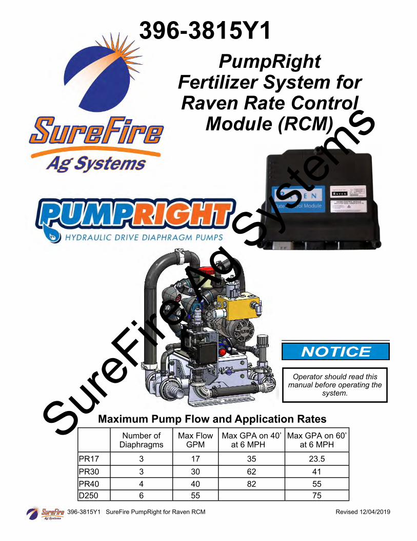
396-3815Y1 SureFire PumpRight for Raven RCM Revised 12/04/2019 PumpRight Fertilizer System for Raven Rate Control Module (RCM) 396-3815Y1 Number of Diaphragms Max Flow GPM Max GPA on 40’ at 6 MPH Max GPA on 60’ at 6 MPH PR17 3 17 35 23.5 PR30 3 30 62 41 PR40 4 40 82 55 D250 6 55 75 Maximum Pump Flow and Application Rates Operator should read this manual before operating the system. SureFire Ag Systems
Transcript of 396 3815Y1 - SureFire Ag...2019/12/04 · 396-3815Y1 SureFire PumpRight for Raven RCM 4 Revised...
396-3815Y1 SureFire PumpRight for Raven RCM Revised 12/04/2019
PumpRight Fertilizer System for Raven Rate Control
Module (RCM)
396-3815Y1
Number of Diaphragms
Max Flow GPM
Max GPA on 40’ at 6 MPH
Max GPA on 60’ at 6 MPH
PR17 3 17 35 23.5
PR30 3 30 62 41
PR40 4 40 82 55
D250 6 55 75
Maximum Pump Flow and Application Rates
Operator should read this manual before operating the
system.
SureFire
Ag Sys
tems

SureFire
Ag Sys
tems
396-3815Y1 SureFire PumpRight for Raven RCM Revised 12/04/2019
Table Of Contents
A Introduction
Introduction • SAFETY INFORMATION—READ THIS • Basic Steps to Install your Fertilizer System ..................................................... 1 • Complete Fertilizer System Example Drawing .................................................. 2-3
B Components
Liquid
Components - Liquid • Flowmeters, Section Valves .............................................................................. 4-6 • Pressure Sensor, Pump Priming and Air Bleed Valve ...................................... 7-8 • Recirculation & Agitation ................................................................................... 9 • Flow Indicators and Manifolds, Check Valves, Orifice Charts ........................... 10-16 • Dual Check Valve Systems, Row Distribution ................................................... 18-21
D Components
Wiring & Elec.
Components - Wiring & Electrical • Connecting to Raven RCM ................................................................................ 22-23 • Sample Harness Layouts .................................................................................. 24-25 • Harness Drawings ............................................................................................. 26-34
E Installation Overview
Installation Overview • Floating Ball Flow Indicators, PumpRight Installation ....................................... 35-36 • Hydraulic Connections, PWM Valve, Hydraulic Oil Flow Requirements ........... 37-39 • Liquid Plumbing Connections ............................................................................ 40-41
F Setup &
Operation
Setup & Operation • RCM Setup, Main Screen, Menu Structure, Profile, Application Type .............. 42-43 • Section Setup, Pressure Sensor, RPM Sensor ................................................ 44 • Control Valve Setup, Rate Sensor, Flow Cal, Fill Flowmeter, Rates ................. 45 • Pressure Sensor Setup/Calibration, Pump RPM, Unlocks ................................ 46 • Height Switch, Display Setup, Menus ............................................................... 47 • System Enable/Disable (ON/OFF), MANUAL and AUTO Mode Operation ...... 48 • Initial Operation, Manual Operation, Auto Mode Test ....................................... 48 • Diagnostics, System Information ....................................................................... 49 • Tests (Calibrate PWM Limits, Control/Section, Nozzle Flow Check) ................ 49
H Maintenance
& Parts
Maintenance & Parts • Air Bladder, Winterization, Pump Oil, Diaphragm and Valve Replacement. ..... 57 • Pre-season Service ........................................................................................... 58 • Replacing Valves and Diaphragms ................................................................... 59-61 • Diaphragm Pump Assemblies and Parts Information ........................................ 62-91 • PWM Valve and Motor Parts ............................................................................. 92
G Trouble- Shooting
Troubleshooting • Troubleshooting Tips ......................................................................................... 50 • Pump Will Not Turn, Hydraulic Manual Override ............................................... 51 • Rate Fluctuates or Slow Getting to Target Rate ................................................ 52 • Flowmeter Tap Test, Section Valves Won’t Move, Pressure Sensor ................ 53-54 • More Troubleshooting Suggestions and Help ................................................... 55-56
QuickStart Setup Sheet See the sheet for your harness, profile, and product setup ©2010-2019 SureFire Ag Systems—All Rights Reserved
SureFire
Ag Sys
tems
396-3815Y1 SureFire PumpRight for Raven RCM ii Revised 12/04/2019
Safety
TAKE NOTE! THIS SAFETY ALERT SYMBOL FOUND THROUGHOUT THIS MANUAL IS USED TO CALL YOUR
ATTENTION TO INSTRUCTIONS INVOLVING YOUR PERSONAL SAFETY AND THE SAFETY OF OTHERS.
FAILURE TO FOLLOW THESE INSTRUCTIONS CAN RESULT IN INJURY OR DEATH.
THIS SYMBOL MEANS ATTENTION!
BECOME ALERT!
YOUR SAFETY IS INVOLVED!
Note the use of the signal words DANGER, WARNING and CAUTION with the safety messages. The appropriate signal word for each has been selected using the following guidelines:
DANGER: Indicates an imminently hazardous situation that, if not avoided, will result in death or se-rious injury. This signal word is to be limited to the most extreme situations typically for machine components which, for functional purposes, cannot be guarded. WARNING: Indicates a potentially hazardous situation that, if not avoided, could result in death or serious injury, and includes hazards that are exposed when guards are removed. It may also be used to alert against unsafe practices. CAUTION: Indicates a potentially hazardous situation that, if not avoided, may result in minor or moderate injury. It may also be used to alert against unsafe practices.
NOTICE is used to address safety practices not related to personal safety.
SureFire
Ag Sys
tems
396-3815Y1 SureFire PumpRight for Raven RCM iii Revised 12/04/2019
Hydraulic Fluid and Equipment Safety This system uses hydraulic equipment with hydraulic fluid under extremely high pressure. Hydraulic fluid escaping under pressure can have sufficient force to penetrate the skin causing serious injury. Keep all hoses and connections in good serviceable condition. Failure to heed may result in serious personal injury or death. Avoid the hazard by relieving the pressure before disconnecting lines or performing work on the system. Make sure hydraulic fluid connections are tight and all hydraulic hoses and lines are in good condition before applying pressure to the system. Use a piece of paper or cardboard, NOT BODY PARTS, to check for suspected leaks. Wear protective gloves and safety glasses or goggles when working with hydraulic systems. DO NOT DELAY! Check hydraulic hoses and fittings frequently. Loose, broken, and missing hardware can cause equipment to not perform properly and can result in serious injury or death. Hydraulic systems can be hot and cause burns. Before working on any system, wait until the fluid has cooled. If an accident occurs, see a doctor familiar with this type of injury immediately. Any fluid injected into the skin or eyes must be treated within a few hours or gangrene may result.
A Word to the Operator SAFETY IS YOUR RESPONSIBILITY. YOU are the key to safety. It is YOUR responsibility to read and understand the safety messages in this manual. This system may be used to apply many different kinds of agricultural liquid products. Read and follow all label information and instructions related to the handling, storage, and application of the product you are using. All electrical harnessing should be checked regularly and should be routed and secured so it will not be pinched, cut, or stretched. Sure
Fire Ag S
ystem
s

396-3815Y1 SureFire PumpRight for Raven RCM iv Revised 12/04/2019
SureFire
Ag Sys
tems
396-3815Y1 SureFire PumpRight for Raven RCM Revised 12/04/2019
General Description
You have purchased a SureFire fertilizer system for your equipment. This system will be controlled by your in-cab display and Raven Rate Control Module (RCM). The RCM will adjust the speed of the SureFire PumpRight hydraulic pump based on feedback from the flowmeter and vehicle speed. The system is capable of using optional section valves to minimize overlap. The RCM is capable of controlling up to 5 products depending on the exact situation. So, the same RCM that controls this PumpRight system could control additional liquid, dry or anhydrous ammonia products on your equipment. You will need a SureFire RCM adapter harness to connect the RCM to the product harness(es). Setup instructions will be furnished with the adapter harness so all the products controlled with a single RCM controller will work properly. You will use the Virtual Terminal (VT) or Universal Terminal (UT) software on your display to view the RCM on your screen. To do Section Control, presor mapping you will need a Task Controller unlock for your display.
A Introduction
Basic Installation Steps
1. Mount the Raven RCM and connect it to the Implement ISOBUS.
2. Open the packages and familiarize yourself with the components. See the System Overview Example on the following page to see the big picture of how SureFire Fertilizer Systems are installed. Refer to manual sections B & D for component information.
3. Mount the PumpRight pump and make hydraulic connections. See section E for hydraulic plumbing information.
4. Plumb the tank to the PumpRight inlet. See section E for details.
5. Install the plumbing kit including section valves, flow indicator columns / manifolds, check valves, plumbing to each row unit delivery point. See section B for information on these components.
6. Attach the flowmeter outlet to section valve, manifold inlet, or LiquiShift inlet. Attach section valve outlets to flow indicator inlets.
7. Attach harnesses as shown in Section D.
8. Set up RCM for SureFire fertilizer system as shown in Section F or in the setup instructions sent with the RCM adapter harness.
9. Fill system with water, conduct initial operation and tests per Section F or in the QuickStart instructions.
10. Winterize system with RV Antifreeze if freezing temperatures are expected.
11. Do pre-season service each year as described at end of manual.
SureFire
Ag Sys
tems
396-3815Y1 SureFire PumpRight for Raven RCM 2 Revised 12/04/2019
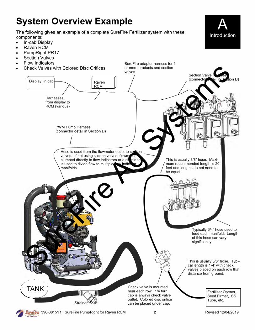
System Overview Example
The following gives an example of a complete SureFire Fertilizer system with these components: • In-cab Display • Raven RCM • PumpRight PR17 • Section Valves • Flow Indicators • Check Valves with Colored Disc Orifices
A Introduction
Raven RCM
Display in cab
Harnesses from display to RCM (various)
Fertilizer Opener, Seed Firmer, SS Tube, etc.
Typically 3/4” hose used to feed each manifold. Length of this hose can vary significantly.
This is usually 3/8” hose. Typi-cal length is 1-4’ with check valves placed on each row that distance from ground.
This is usually 3/8” hose. Maxi-mum recommended length is 20 feet and lengths do not need to be equal.
Check valve is mounted near each row. 1/4 turn cap is always check valve outlet. Colored disc orifice can be placed under cap.
TANK
Hose is used from the flowmeter outlet to section valves. If not using section valves, flowmeter is plumbed directly to flow indicators or a simple tee is used to divide flow to multiple flow indicator manifolds.
Strainer
PWM Pump Harness (connector detail in Section D)
Section Valve Harness (connector detail in Section D)
SureFire adapter harness for 1 or more products and section valves
SureFire
Ag Sys
tems
396-3815Y1 SureFire PumpRight for Raven RCM 3 Revised 12/04/2019
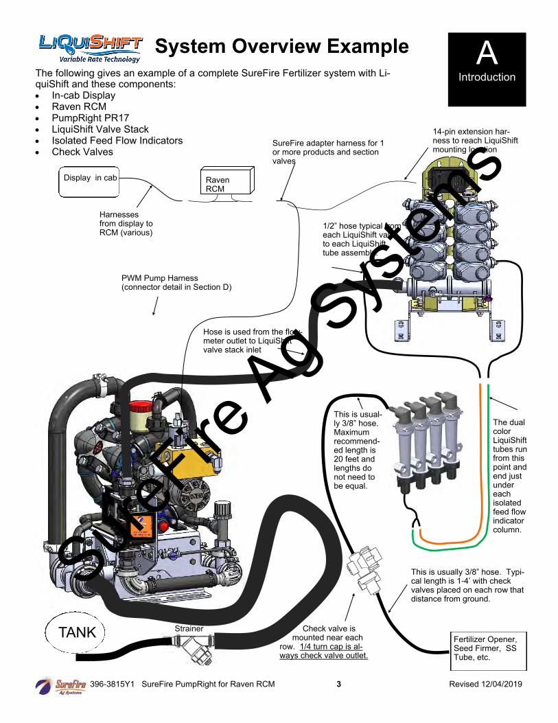
System Overview Example A Introduction
Raven RCM
Display in cab
Harnesses from display to RCM (various)
Fertilizer Opener, Seed Firmer, SS Tube, etc.
The dual color LiquiShift tubes run from this point and end just under each isolated feed flow indicator column.
This is usually 3/8” hose. Typi-cal length is 1-4’ with check valves placed on each row that distance from ground.
This is usual-ly 3/8” hose. Maximum recommend-ed length is 20 feet and lengths do not need to be equal.
Check valve is mounted near each
row. 1/4 turn cap is al-ways check valve outlet.
Hose is used from the flow-meter outlet to LiquiShift valve stack inlet
PWM Pump Harness (connector detail in Section D)
14-pin extension har-ness to reach LiquiShift mounting location
The following gives an example of a complete SureFire Fertilizer system with Li-quiShift and these components: • In-cab Display • Raven RCM • PumpRight PR17 • LiquiShift Valve Stack • Isolated Feed Flow Indicators • Check Valves
SureFire adapter harness for 1 or more products and section valves
1/2” hose typical from each LiquiShift valve to each LiquiShift tube assembly.
TANK Strainer
SureFire
Ag Sys
tems

396-3815Y1 SureFire PumpRight for Raven RCM 4 Revised 12/04/2019
PR17 & PR30 Electromagnetic Flowmeter Kits 0.13 - 2.6 GPM Item Number 500-02-2082 (PR17) 0.3 - 5 GPM Item Number 500-02-2085 (PR17) 0.6 - 13 GPM Item Number 500-02-2090 (PR17 & PR30) 1.3 - 26 GPM Item Number 500-02-2095 (PR30) Kits include flowmeter, adapter harness, mounting bracket, hose barb fittings & hose clamps.
Flowmeter Model (black meter with orange label)
JD GRC Flow Calibration FPT Size
Hose Barb In kit
0.13 - 2.6 GPM 3000 3/4” 1”
0.3 - 5 GPM 3000 3/4” 1”
0.6 - 13 GPM 2000 3/4” 1”
1.3 - 26 GPM 2000 1” 1”
B Components
Liquid
Earlier model flowmeters (meters with white labels with black text) have different calibration numbers. See the documentation for those meters to find the calibration numbers.
-Before doing any arc welding on the implement, unplug the cable to the flowmeter, or damage to the flowmeter may result.
-Do not power wash the flowmeter. High pressure spray directed at the back edge of the face plate or at the wire connector may allow water into the flowmeter electronics.
Amp SuperSeal 3-pin connector Use adapter 201-17842
to connect to 3-pin MP harness
Mounting Bracket, 400-3826Y1 (QTY 1) (not used for PR40 and D250 Pump)
Mounting Bracket, 410-4015Y1 (QTY 1) (not used for PR40 and D250 Pump)
Troubleshooting Tip:
3-pin MP Tower A- Signal B- 12V Power C- Ground (See the next page for more flowmeter tips)
3-pin AMP SuperSeal 1– Ground 2– 12V Power 3– Signal
Remove red guard to reach pins. Be careful so you don’t break red side keepers.
1 2 3
Electromagnetic flowmeters are superior to traditional turbine flowmeters in two basic ways. First, they have no moving parts. There are no wear items or potential for contaminants to jam a spinning turbine. Second, electromagnetic flowmeters detect the flow by electrically measuring the velocity of the liquid, which makes them independent of viscosity or density of the fluid measured. They are extremely accurate using the standard calibration number. SureFire still recommends you perform a catch test to verify the system is properly installed and configured. Sure
Fire Ag S
ystem
s
396-3815Y1 SureFire PumpRight for Raven RCM 5 Revised 12/04/2019
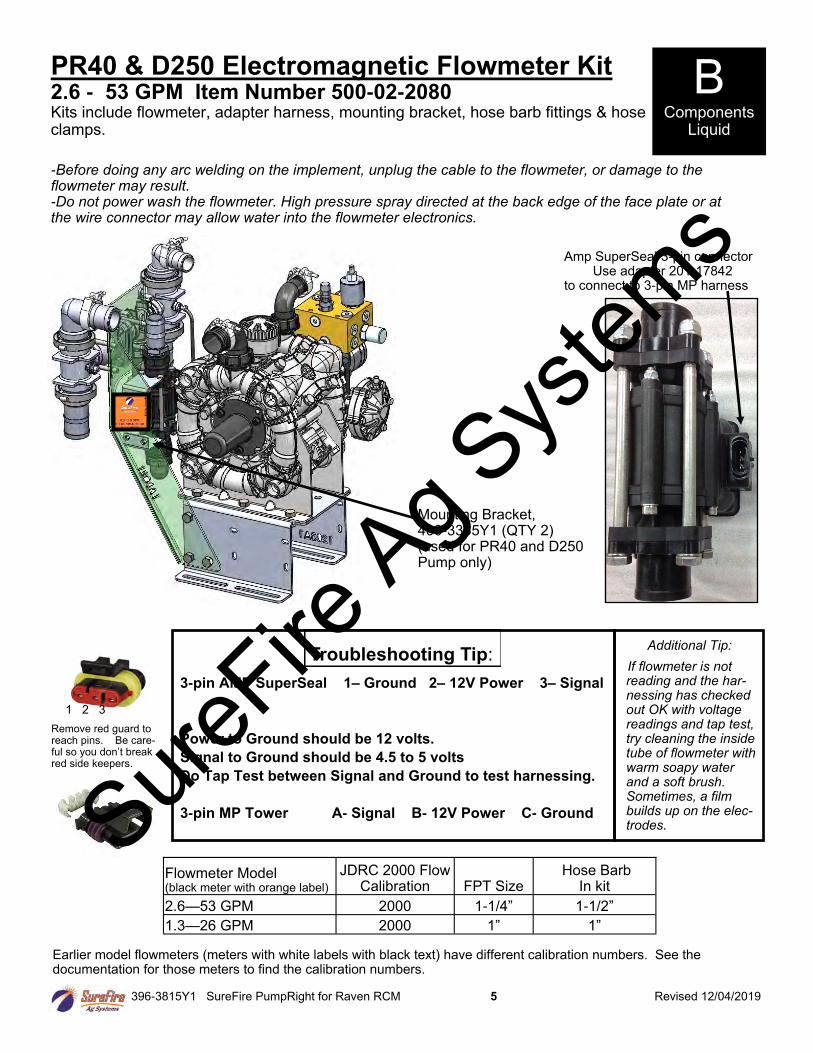
PR40 & D250 Electromagnetic Flowmeter Kit 2.6 - 53 GPM Item Number 500-02-2080 Kits include flowmeter, adapter harness, mounting bracket, hose barb fittings & hose clamps.
Flowmeter Model (black meter with orange label)
JDRC 2000 Flow Calibration FPT Size
Hose Barb In kit
2.6—53 GPM 2000 1-1/4” 1-1/2”
1.3—26 GPM 2000 1” 1”
B Components
Liquid
Earlier model flowmeters (meters with white labels with black text) have different calibration numbers. See the documentation for those meters to find the calibration numbers.
Amp SuperSeal 3-pin connector Use adapter 201-17842
to connect to 3-pin MP harness
-Before doing any arc welding on the implement, unplug the cable to the flowmeter, or damage to the flowmeter may result. -Do not power wash the flowmeter. High pressure spray directed at the back edge of the face plate or at the wire connector may allow water into the flowmeter electronics.
Mounting Bracket, 400-3335Y1 (QTY 2) (used for PR40 and D250 Pump only)
Troubleshooting Tip:
Remove red guard to reach pins. Be care-ful so you don’t break red side keepers.
1 2 3
3-pin AMP SuperSeal 1– Ground 2– 12V Power 3– Signal
Power to Ground should be 12 volts.
Signal to Ground should be 4.5 to 5 volts
Do Tap Test between Signal and Ground to test harnessing.
3-pin MP Tower A- Signal B- 12V Power C- Ground
Additional Tip:
If flowmeter is not reading and the har-nessing has checked out OK with voltage readings and tap test, try cleaning the inside tube of flowmeter with warm soapy water and a soft brush. Sometimes, a film builds up on the elec-trodes. Sure
Fire Ag S
ystem
s
396-3815Y1 SureFire PumpRight for Raven RCM 6 Revised 12/04/2019
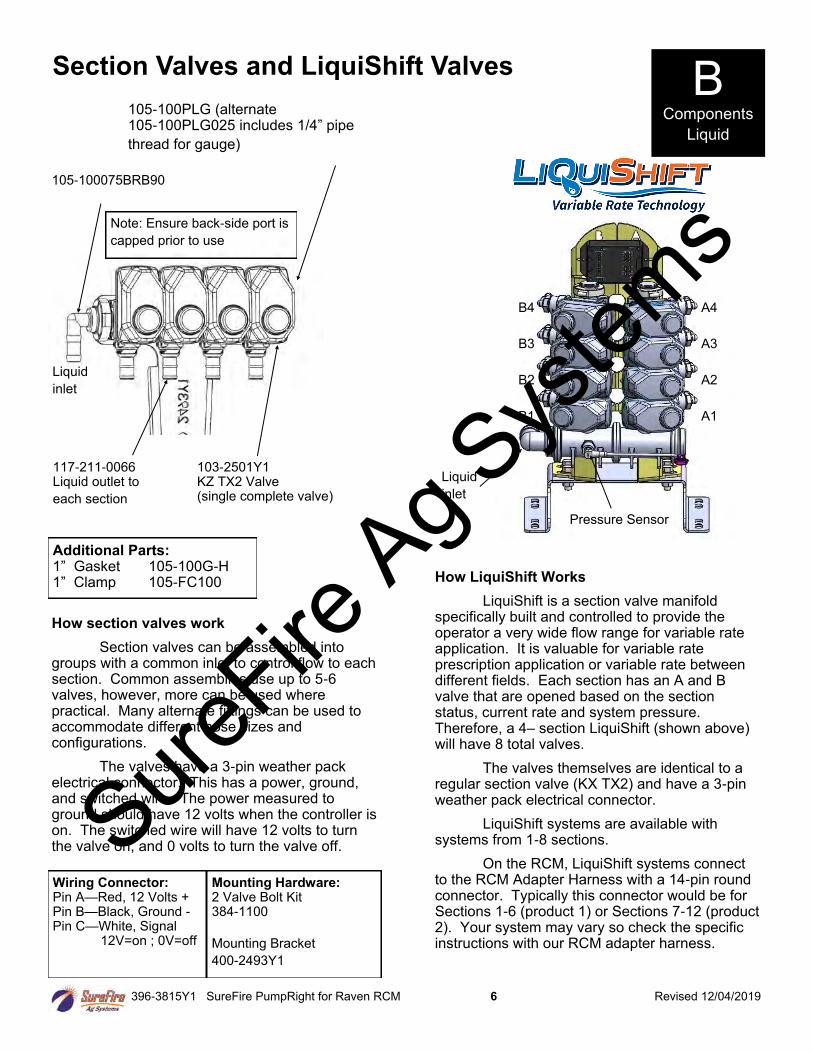
Section Valves and LiquiShift Valves
Liquid
inlet
105-100075BRB90
105-100PLG (alternate 105-100PLG025 includes 1/4” pipe
thread for gauge)
103-2501Y1 KZ TX2 Valve (single complete valve)
117-211-0066 Liquid outlet to
each section
Additional Parts: 1” Gasket 105-100G-H 1” Clamp 105-FC100
How section valves work
Section valves can be assembled into groups with a common inlet to control flow to each section. Common assemblies use up to 5-6 valves, however, more can be used where practical. Many alternate fittings can be used to accommodate different hose sizes and configurations.
The valves have a 3-pin weather pack electrical connector. This has a power, ground, and switched wire. The power measured to ground should have 12 volts when the controller is on. The switched wire will have 12 volts to turn the valve on, and 0 volts to turn the valve off.
Wiring Connector: Pin A—Red, 12 Volts + Pin B—Black, Ground - Pin C—White, Signal 12V=on ; 0V=off
Mounting Hardware: 2 Valve Bolt Kit 384-1100
Mounting Bracket
400-2493Y1
B Components
Liquid
Note: Ensure back-side port is
capped prior to use
How LiquiShift Works
LiquiShift is a section valve manifold specifically built and controlled to provide the operator a very wide flow range for variable rate application. It is valuable for variable rate prescription application or variable rate between different fields. Each section has an A and B valve that are opened based on the section status, current rate and system pressure. Therefore, a 4– section LiquiShift (shown above) will have 8 total valves.
The valves themselves are identical to a regular section valve (KX TX2) and have a 3-pin weather pack electrical connector.
LiquiShift systems are available with systems from 1-8 sections.
On the RCM, LiquiShift systems connect to the RCM Adapter Harness with a 14-pin round connector. Typically this connector would be for Sections 1-6 (product 1) or Sections 7-12 (product 2). Your system may vary so check the specific instructions with our RCM adapter harness.
Liquid
inlet
Pressure Sensor
A4
A3
A2
A1
B4
B3
B2
B1
SureFire
Ag Sys
tems
396-3815Y1 SureFire PumpRight for Raven RCM 7 Revised 12/04/2019
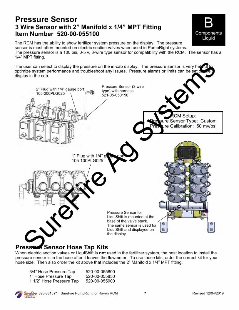
The RCM has the ability to show fertilizer system pressure on the display. The pressure sensor is most often mounted on electric section valves when used in PumpRight systems. The pressure sensor is a 100 psi, 0-5 v, 3-wire type sensor for compatibility with the RCM. The sensor has a 1/4” MPT fitting. The user can select to display the pressure on the in-cab display. The pressure sensor is very helpful to optimize system performance and troubleshoot any issues. Pressure alarms or limits can be set on the display in the cab.
Pressure Sensor 3 Wire Sensor with 2” Manifold x 1/4” MPT Fitting Item Number 520-00-055100
B Components
Liquid
Pressure Sensor (3 wire type) with harness 521-05-050150
2” Plug with 1/4” gauge port 105-200PLG025
Pressure Sensor Hose Tap Kits When electric section valves or LiquiShift is not used in the fertilizer system, the best location to install the pressure sensor is in the hose after it leaves the flowmeter. To use these kits, order the correct kit for your hose size. Then also order the kit above that includes the 2” Manifold x 1/4” MPT fitting.
3/4” Hose Pressure Tap 520-00-055800 1” Hose Pressure Tap 520-00-055850 1 1/2” Hose Pressure Tap 520-00-055900
RCM Setup: Pressure Sensor Type: Custom Pressure Calibration: 50 mv/psi
1” Plug with 1/4” gauge port 105-100PLG025
Pressure Sensor for LiquiShift is mounted at the base of the valve stack. The same sensor is used for LiquiShift and displayed on the display. Sure
Fire Ag S
ystem
s
396-3815Y1 SureFire PumpRight for Raven RCM 8 Revised 12/04/2019
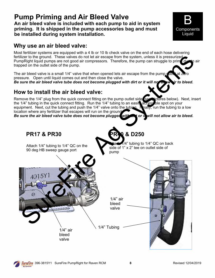
Pump Priming and Air Bleed Valve An air bleed valve is included with each pump to aid in system priming. It is shipped in the pump accessories bag and must be installed during system installation.
Why use an air bleed valve: Most fertilizer systems are equipped with a 4 lb or 10 lb check valve on the end of each hose delivering fertilizer to the ground. These valves do not let air escape from the system, unless it is pressurized. PumpRight liquid pumps are not good air compressors. Therefore, the pump can struggle to prime due to air trapped on the outlet side of the pump. The air bleed valve is a small 1/4” valve that when opened lets air escape from the pump outlet at zero pressure. Open until liquid comes out and then close the valve. Be sure the air bleed valve tube does not become plugged with dirt or it will not allow air to bleed.
How to install the air bleed valve: Remove the 1/4” plug from the quick connect fitting on the pump outlet side (see pictures below). Next, insert the 1/4” tubing in the quick connect fitting. Run the 1/4” tubing to an easily accessible spot on your equipment. Next, cut the tubing and push the 1/4” valve onto the tubing. Finally, run the tubing to a low location where any fertilizer that escapes will run on the ground. Be sure the air bleed valve tube does not become plugged with dirt or it will not allow air to bleed.
B Components
Liquid
PR17 & PR30 PR40 & D250
1/4” Tubing
Attach 1/4” tubing to 1/4” QC on the 90 deg HB sweep gauge port
1/4” air bleed valve
Attach 1/4” tubing to 1/4” QC on back side of 1” x 2” tee on outlet side of pump
1/4” air bleed valve
SureFire
Ag Sys
tems
396-3815Y1 SureFire PumpRight for Raven RCM 9 Revised 12/04/2019
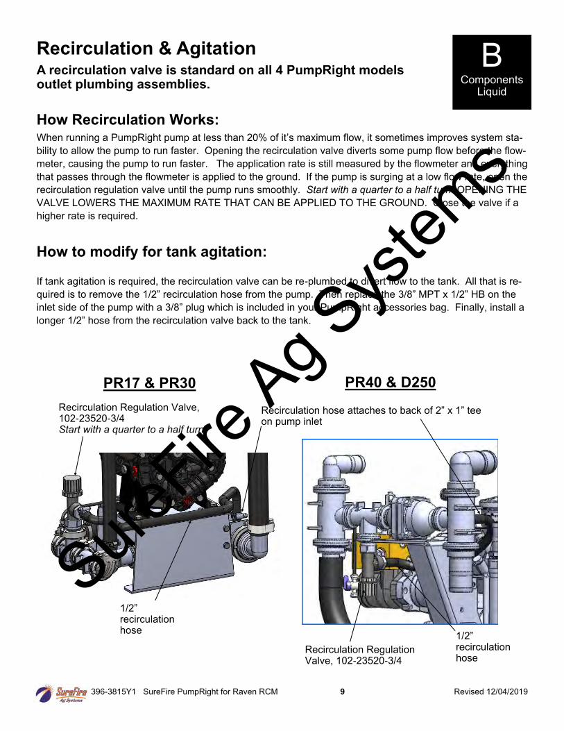
Recirculation & Agitation A recirculation valve is standard on all 4 PumpRight models outlet plumbing assemblies.
How Recirculation Works: When running a PumpRight pump at less than 20% of it’s maximum flow, it sometimes improves system sta-
bility to allow the pump to run faster. Opening the recirculation valve diverts some pump flow before the flow-
meter, causing the pump to run faster. The application rate is still measured by the flowmeter and everything
that passes through the flowmeter is applied to the ground. If the pump is surging at a low flow rate, open the
recirculation regulation valve until the pump runs smoothly. Start with a quarter to a half turn. OPENING THE
VALVE LOWERS THE MAXIMUM RATE THAT CAN BE APPLIED TO THE GROUND. Close the valve if a
higher rate is required.
1/2” recirculation hose
Recirculation Regulation Valve, 102-23520-3/4 Start with a quarter to a half turn.
How to modify for tank agitation: If tank agitation is required, the recirculation valve can be re-plumbed to divert flow to the tank. All that is re-
quired is to remove the 1/2” recirculation hose from the pump. Then replace the 3/8” MPT x 1/2” HB on the
inlet side of the pump with a 3/8” plug which is included in your PumpRight accessories bag. Finally, install a
longer 1/2” hose from the recirculation valve back to the tank.
PR17 & PR30 PR40 & D250
Recirculation Regulation Valve, 102-23520-3/4
1/2” recirculation hose
B Components
Liquid
Recirculation hose attaches to back of 2” x 1” tee on pump inlet
SureFire
Ag Sys
tems
396-3815Y1 SureFire PumpRight for Raven RCM 10 Revised 12/04/2019
Parts List
Complete Columns
701-20460-950 Single Full Flow Column with 3/8" HB - 90 Degree Outlet 701-20460-940 Single Full Flow Column with 3/8” QC - 90 Degree Outlet
701-20460-960 Single Full Flow Column with 1/2” HB - 90 Degree Outlet 701-20460-935 Single Low Flow Column with 3/8” QC - 90 Degree Outlet 701-20460-920 Single Low Flow Column with 1/4" QC - 90 Degree Outlet
Fittings
701-20503-00 ORS x 3/4" HB - Straight Service Parts Only 701-20511-00 ORS x 3/8" HB - 90 Degree 701-20460-02 Wilger Flow Indicator Ball Retainer 701-20512-00 ORS x 1/2" HB - 90 Degree 701-20460-03 FKM O-Ring for indicator body & fittings
701-20513-00 ORS x 3/4" HB - 90 Degree 701-20460-04 Wilger Lock U-clip
701-20516-00 ORS x 1/4" QC - 90 Degree 701-20460-05 Flow Indicator Ball - 1/2" SS Ball
701-20517-00 ORS x 3/8" QC - 90 Degree 701-20460-06 Flow Indicator Ball - Maroon Glass 701-20518-00 ORS x 1/4" FPT - 90 Degree 701-20460-07 Flow Indicator Ball - Red Celcon 701-20519-00 ORS x 1/4" FPT - Straight 701-20460-08 Flow Indicator Ball - Green Poly 701-20520-00 ORS Male x ORS Female - 90 degree 701-20460-09 Flow Indicator Ball - Black Poly
701-20521-00 Wilger End Cap 701-20460-15 Viton O-Ring for column & fittings 701-20523-00 ORS Male x ORS Female x 3/8" FPT - Isolator 701-40225-05 Viton O-Ring for Orifice 701-20525-00 ORS Male x ORS Male x 1" FPT - Tee
Brackets & U-Bolts
400-1037A1 3-6 Row Bracket
400-3155Y1 7-12 Row Bracket
400-2011A1 White Backer Plate for 3-6 Row Bracket
400-2010A1 White Backer Plate for 7-12 Row Bracket
400-1315A2 Flow Indicator Bracket, 6-8 in wide hitch mount
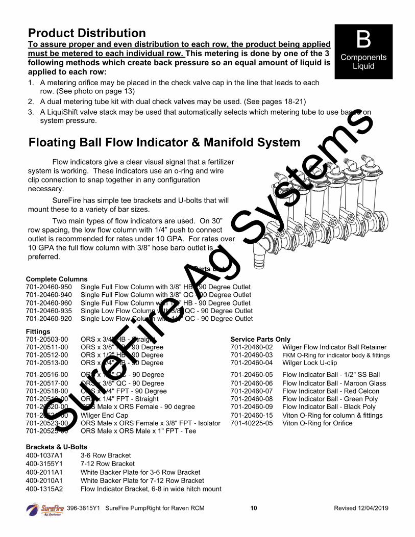
Product Distribution
To assure proper and even distribution to each row, the product being applied must be metered to each individual row. This metering is done by one of the 3 following methods which create back pressure so an equal amount of liquid is applied to each row:
1. A metering orifice may be placed in the check valve cap in the line that leads to each row. (See photo on page 13)
2. A dual metering tube kit with dual check valves may be used. (See pages 18-21)
3. A LiquiShift valve stack may be used that automatically selects which metering tube to use based on system pressure.
B Components
Liquid
Floating Ball Flow Indicator & Manifold System
Flow indicators give a clear visual signal that a fertilizer
system is working. These indicators use an o-ring and wire
clip connection to snap together in any configuration
necessary.
SureFire has simple tee brackets and U-bolts that will
mount these to a variety of bar sizes.
Two main types of flow indicators are used. On 30”
row spacing, the low flow column with 1/4” push to connect
outlet is recommended for rates under 10 GPA. For rates over
10 GPA the full flow column with 3/8” hose barb outlet is
preferred.
SureFire
Ag Sys
tems
396-3815Y1 SureFire PumpRight for Raven RCM 11 Revised 12/04/2019
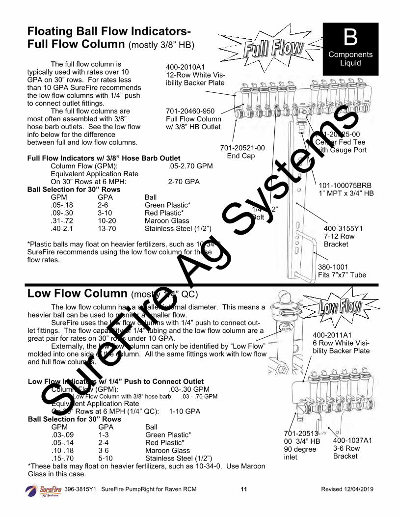
701-20521-00 End Cap
400-3155Y1 7-12 Row Bracket
101-100075BRB 1” MPT x 3/4” HB
The full flow column is typically used with rates over 10 GPA on 30” rows. For rates less than 10 GPA SureFire recommends the low flow columns with 1/4” push to connect outlet fittings. The full flow columns are most often assembled with 3/8” hose barb outlets. See the low flow info below for the difference between full and low flow columns.
701-20460-950 Full Flow Column w/ 3/8” HB Outlet
701-20525-00 Center Fed Tee with Gauge Port
380-1001 Fits 7”x7” Tube
Full Flow Indicators w/ 3/8” Hose Barb Outlet Column Flow (GPM): .05-2.70 GPM Equivalent Application Rate On 30” Rows at 6 MPH: 2-70 GPA
Ball Selection for 30” Rows GPM GPA Ball .05-.18 2-6 Green Plastic* .09-.30 3-10 Red Plastic* .31-.72 10-20 Maroon Glass .40-2.1 13-70 Stainless Steel (1/2”)
*Plastic balls may float on heavier fertilizers, such as 10-34-0. SureFire recommends using the low flow column for these flow rates.
1/4” x 2” Bolt
Floating Ball Flow Indicators- Full Flow Column (mostly 3/8” HB) B
Components Liquid
400-2010A1 12-Row White Vis-ibility Backer Plate
400-1037A1 3-6 Row Bracket
400-2011A1 6 Row White Visi-bility Backer Plate
701-20513-00 3/4” HB 90 degree inlet
Low Flow Column (mostly 1/4” QC) The low flow column has a smaller internal diameter. This means a heavier ball can be used to monitor a smaller flow. SureFire uses the low flow columns with 1/4” push to connect out-let fittings. The flow capability of 1/4” tubing and the low flow column are a great pair for rates on 30” rows under 10 GPA. Externally, the low flow column can only be identified by “Low Flow” molded into one side of the column. All the same fittings work with low flow and full flow columns.
Low Flow Indicators w/ 1/4” Push to Connect Outlet Column Flow (GPM): .03-.30 GPM *** Low Flow Column with 3/8” hose barb .03 - .70 GPM
Equivalent Application Rate On 30” Rows at 6 MPH (1/4” QC): 1-10 GPA
Ball Selection for 30” Rows GPM GPA Ball .03-.09 1-3 Green Plastic* .05-.14 2-4 Red Plastic* .10-.18 3-6 Maroon Glass .15-.70 5-10 Stainless Steel (1/2”)
*These balls may float on heavier fertilizers, such as 10-34-0. Use Maroon Glass in this case.
SureFire
Ag Sys
tems
396-3815Y1 SureFire PumpRight for Raven RCM 12 Revised 12/04/2019
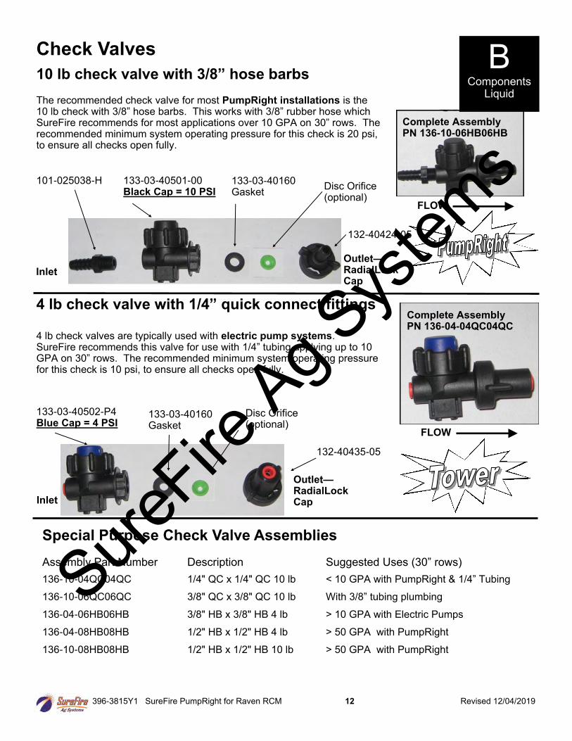
The recommended check valve for most PumpRight installations is the 10 lb check with 3/8” hose barbs. This works with 3/8” rubber hose which SureFire recommends for most applications over 10 GPA on 30” rows. The recommended minimum system operating pressure for this check is 20 psi, to ensure all checks open fully.
Check Valves
Complete Assembly PN 136-10-06HB06HB
101-025038-H 133-03-40501-00 Black Cap = 10 PSI
Disc Orifice (optional)
133-03-40160 Gasket
Inlet
Outlet—RadialLock Cap
4 lb check valves are typically used with electric pump systems. SureFire recommends this valve for use with 1/4” tubing applying up to 10 GPA on 30” rows. The recommended minimum system operating pressure for this check is 10 psi, to ensure all checks open fully.
133-03-40502-P4 Blue Cap = 4 PSI
Disc Orifice (optional)
133-03-40160 Gasket
Inlet
Outlet—RadialLock Cap
4 lb check valve with 1/4” quick connect fittings
Assembly Part Number Description Suggested Uses (30” rows)
136-10-04QC04QC 1/4" QC x 1/4" QC 10 lb < 10 GPA with PumpRight & 1/4” Tubing
136-10-06QC06QC 3/8" QC x 3/8" QC 10 lb With 3/8” tubing plumbing
136-04-06HB06HB 3/8" HB x 3/8" HB 4 lb > 10 GPA with Electric Pumps
136-04-08HB08HB 1/2" HB x 1/2" HB 4 lb > 50 GPA with PumpRight
136-10-08HB08HB 1/2" HB x 1/2" HB 10 lb > 50 GPA with PumpRight
Special Purpose Check Valve Assemblies
132-40435-05
Complete Assembly PN 136-04-04QC04QC
10 lb check valve with 3/8” hose barbs B
Components Liquid
132-40424-05
FLOW
FLOW
SureFire
Ag Sys
tems
396-3815Y1 SureFire PumpRight for Raven RCM 13 Revised 12/04/2019
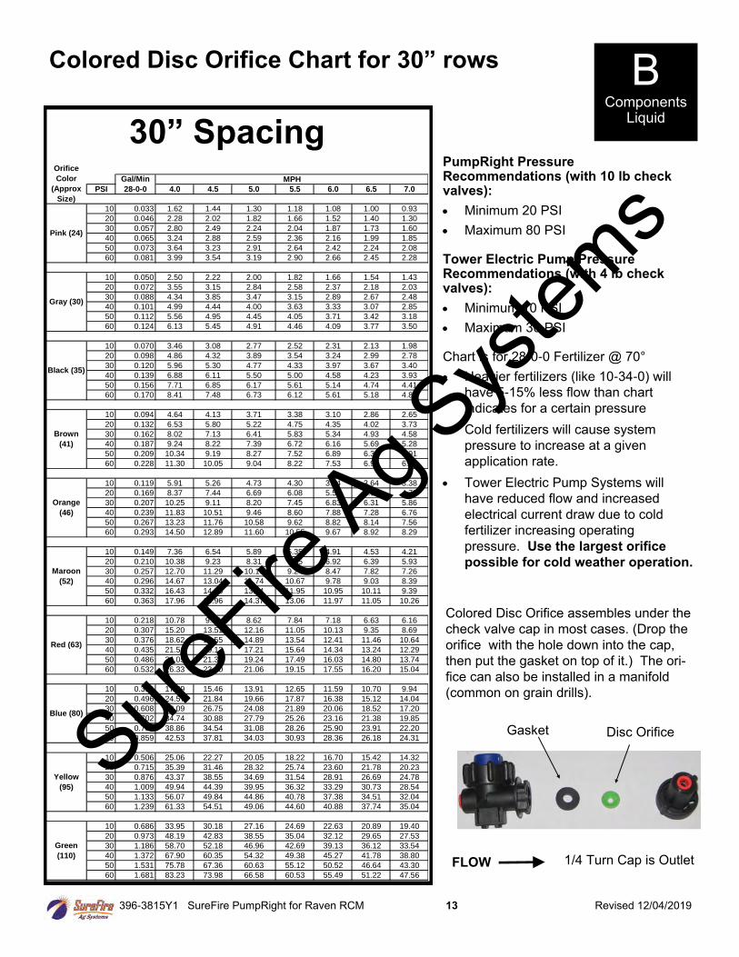
Colored Disc Orifice Chart for 30” rows B
Components Liquid
PumpRight Pressure Recommendations (with 10 lb check valves):
• Minimum 20 PSI
• Maximum 80 PSI Tower Electric Pump Pressure Recommendations (with 4 lb check valves):
• Minimum 10 PSI
• Maximum 30 PSI Chart is for 28-0-0 Fertilizer @ 70°
• Heavier fertilizers (like 10-34-0) will
have 5-15% less flow than chart
indicates for a certain pressure
• Cold fertilizers will cause system
pressure to increase at a given
application rate.
• Tower Electric Pump Systems will
have reduced flow and increased
electrical current draw due to cold
fertilizer increasing operating
pressure. Use the largest orifice
possible for cold weather operation.
PSI 4.0 4.5 5.0 5.5 6.0 6.5 7.0
10 0.033 1.62 1.44 1.30 1.18 1.08 1.00 0.93
20 0.046 2.28 2.02 1.82 1.66 1.52 1.40 1.30
30 0.057 2.80 2.49 2.24 2.04 1.87 1.73 1.60
40 0.065 3.24 2.88 2.59 2.36 2.16 1.99 1.85
50 0.073 3.64 3.23 2.91 2.64 2.42 2.24 2.08
60 0.081 3.99 3.54 3.19 2.90 2.66 2.45 2.28
10 0.050 2.50 2.22 2.00 1.82 1.66 1.54 1.43
20 0.072 3.55 3.15 2.84 2.58 2.37 2.18 2.03
30 0.088 4.34 3.85 3.47 3.15 2.89 2.67 2.48
40 0.101 4.99 4.44 4.00 3.63 3.33 3.07 2.85
50 0.112 5.56 4.95 4.45 4.05 3.71 3.42 3.18
60 0.124 6.13 5.45 4.91 4.46 4.09 3.77 3.50
10 0.070 3.46 3.08 2.77 2.52 2.31 2.13 1.98
20 0.098 4.86 4.32 3.89 3.54 3.24 2.99 2.78
30 0.120 5.96 5.30 4.77 4.33 3.97 3.67 3.40
40 0.139 6.88 6.11 5.50 5.00 4.58 4.23 3.93
50 0.156 7.71 6.85 6.17 5.61 5.14 4.74 4.41
60 0.170 8.41 7.48 6.73 6.12 5.61 5.18 4.81
10 0.094 4.64 4.13 3.71 3.38 3.10 2.86 2.65
20 0.132 6.53 5.80 5.22 4.75 4.35 4.02 3.73
30 0.162 8.02 7.13 6.41 5.83 5.34 4.93 4.58
40 0.187 9.24 8.22 7.39 6.72 6.16 5.69 5.28
50 0.209 10.34 9.19 8.27 7.52 6.89 6.36 5.91
60 0.228 11.30 10.05 9.04 8.22 7.53 6.95 6.46
10 0.119 5.91 5.26 4.73 4.30 3.94 3.64 3.38
20 0.169 8.37 7.44 6.69 6.08 5.58 5.15 4.78
30 0.207 10.25 9.11 8.20 7.45 6.83 6.31 5.86
40 0.239 11.83 10.51 9.46 8.60 7.88 7.28 6.76
50 0.267 13.23 11.76 10.58 9.62 8.82 8.14 7.56
60 0.293 14.50 12.89 11.60 10.55 9.67 8.92 8.29
10 0.149 7.36 6.54 5.89 5.35 4.91 4.53 4.21
20 0.210 10.38 9.23 8.31 7.55 6.92 6.39 5.93
30 0.257 12.70 11.29 10.16 9.24 8.47 7.82 7.26
40 0.296 14.67 13.04 11.74 10.67 9.78 9.03 8.39
50 0.332 16.43 14.60 13.14 11.95 10.95 10.11 9.39
60 0.363 17.96 15.96 14.37 13.06 11.97 11.05 10.26
10 0.218 10.78 9.58 8.62 7.84 7.18 6.63 6.16
20 0.307 15.20 13.51 12.16 11.05 10.13 9.35 8.69
30 0.376 18.62 16.55 14.89 13.54 12.41 11.46 10.64
40 0.435 21.51 19.12 17.21 15.64 14.34 13.24 12.29
50 0.486 24.05 21.38 19.24 17.49 16.03 14.80 13.74
60 0.532 26.33 23.40 21.06 19.15 17.55 16.20 15.04
10 0.351 17.39 15.46 13.91 12.65 11.59 10.70 9.94
20 0.496 24.57 21.84 19.66 17.87 16.38 15.12 14.04
30 0.608 30.09 26.75 24.08 21.89 20.06 18.52 17.20
40 0.702 34.74 30.88 27.79 25.26 23.16 21.38 19.85
50 0.785 38.86 34.54 31.08 28.26 25.90 23.91 22.20
60 0.859 42.53 37.81 34.03 30.93 28.36 26.18 24.31
10 0.506 25.06 22.27 20.05 18.22 16.70 15.42 14.32
20 0.715 35.39 31.46 28.32 25.74 23.60 21.78 20.23
30 0.876 43.37 38.55 34.69 31.54 28.91 26.69 24.78
40 1.009 49.94 44.39 39.95 36.32 33.29 30.73 28.54
50 1.133 56.07 49.84 44.86 40.78 37.38 34.51 32.04
60 1.239 61.33 54.51 49.06 44.60 40.88 37.74 35.04
10 0.686 33.95 30.18 27.16 24.69 22.63 20.89 19.40
20 0.973 48.19 42.83 38.55 35.04 32.12 29.65 27.53
30 1.186 58.70 52.18 46.96 42.69 39.13 36.12 33.54
40 1.372 67.90 60.35 54.32 49.38 45.27 41.78 38.80
50 1.531 75.78 67.36 60.63 55.12 50.52 46.64 43.30
60 1.681 83.23 73.98 66.58 60.53 55.49 51.22 47.56
Brown
(41)
Green
(110)
Orange
(46)
Maroon
(52)
Red (63)
Blue (80)
Yellow
(95)
MPH
Pink (24)
Gray (30)
Black (35)
Gal/Min
28-0-0
Orifice
Color
(Approx
Size)
30” Spacing
Colored Disc Orifice assembles under the
check valve cap in most cases. (Drop the
orifice with the hole down into the cap,
then put the gasket on top of it.) The ori-
fice can also be installed in a manifold
(common on grain drills).
Disc Orifice Gasket
FLOW 1/4 Turn Cap is Outlet
SureFire
Ag Sys
tems
396-3815Y1 SureFire PumpRight for Raven RCM 14 Revised 12/04/2019
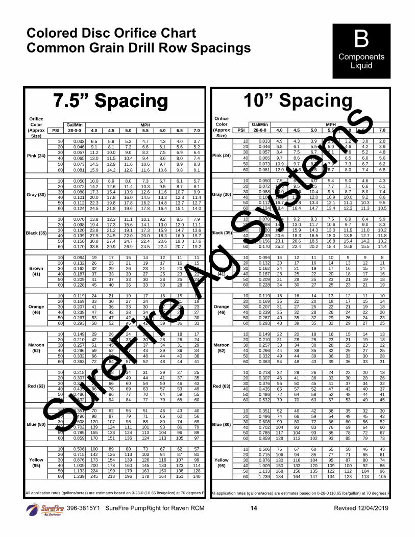
Colored Disc Orifice Chart Common Grain Drill Row Spacings
B Components
Liquid
7.5” Spacing
PSI 4.0 4.5 5.0 5.5 6.0 6.5 7.0
10 0.033 6.5 5.8 5.2 4.7 4.3 4.0 3.7
20 0.046 9.1 8.1 7.3 6.6 6.1 5.6 5.2
30 0.057 11.2 10.0 9.0 8.2 7.5 6.9 6.4
40 0.065 13.0 11.5 10.4 9.4 8.6 8.0 7.4
50 0.073 14.5 12.9 11.6 10.6 9.7 8.9 8.3
60 0.081 15.9 14.2 12.8 11.6 10.6 9.8 9.1
10 0.050 10.0 8.9 8.0 7.3 6.7 6.1 5.7
20 0.072 14.2 12.6 11.4 10.3 9.5 8.7 8.1
30 0.088 17.3 15.4 13.9 12.6 11.6 10.7 9.9
40 0.101 20.0 17.8 16.0 14.5 13.3 12.3 11.4
50 0.112 22.3 19.8 17.8 16.2 14.8 13.7 12.7
60 0.124 24.5 21.8 19.6 17.8 16.4 15.1 14.0
10 0.070 13.8 12.3 11.1 10.1 9.2 8.5 7.9
20 0.098 19.4 17.3 15.6 14.1 13.0 12.0 11.1
30 0.120 23.8 21.2 19.1 17.3 15.9 14.7 13.6
40 0.139 27.5 24.5 22.0 20.0 18.3 16.9 15.7
50 0.156 30.8 27.4 24.7 22.4 20.6 19.0 17.6
60 0.170 33.6 29.9 26.9 24.5 22.4 20.7 19.2
10 0.094 19 17 15 14 12 11 11
20 0.132 26 23 21 19 17 16 15
30 0.162 32 29 26 23 21 20 18
40 0.187 37 33 30 27 25 23 21
50 0.209 41 37 33 30 28 25 24
60 0.228 45 40 36 33 30 28 26
10 0.119 24 21 19 17 16 15 14
20 0.169 33 30 27 24 22 21 19
30 0.207 41 36 33 30 27 25 23
40 0.239 47 42 38 34 32 29 27
50 0.267 53 47 42 38 35 33 30
60 0.293 58 52 46 42 39 36 33
10 0.149 29 26 24 21 20 18 17
20 0.210 42 37 33 30 28 26 24
30 0.257 51 45 41 37 34 31 29
40 0.296 59 52 47 43 39 36 34
50 0.332 66 58 53 48 44 40 38
60 0.363 72 64 57 52 48 44 41
10 0.218 43 38 34 31 29 27 25
20 0.307 61 54 49 44 41 37 35
30 0.376 74 66 60 54 50 46 43
40 0.435 86 76 69 63 57 53 49
50 0.486 96 86 77 70 64 59 55
60 0.532 105 94 84 77 70 65 60
10 0.351 70 62 56 51 46 43 40
20 0.496 98 87 79 71 66 60 56
30 0.608 120 107 96 88 80 74 69
40 0.702 139 124 111 101 93 86 79
50 0.785 155 138 124 113 104 96 89
60 0.859 170 151 136 124 113 105 97
10 0.506 100 89 80 73 67 62 57
20 0.715 142 126 113 103 94 87 81
30 0.876 173 154 139 126 116 107 99
40 1.009 200 178 160 145 133 123 114
50 1.133 224 199 179 163 150 138 128
60 1.239 245 218 196 178 164 151 140
All application rates (gallons/acres) are estimates based on 0-28-0 (10.65 lbs/gallon) at 70 degrees F.
Brown
(41)
Orange
(46)
Maroon
(52)
Red (63)
Blue (80)
Yellow
(95)
MPH
Pink (24)
Gray (30)
Black (35)
Gal/Min
28-0-0
Orifice
Color
(Approx
Size)
PSI 4.0 4.5 5.0 5.5 6.0 6.5 7.0
10 0.033 4.9 4.3 3.9 3.5 3.2 3.0 2.8
20 0.046 6.8 6.1 5.5 5.0 4.6 4.2 3.9
30 0.057 8.4 7.5 6.7 6.1 5.6 5.2 4.8
40 0.065 9.7 8.6 7.8 7.1 6.5 6.0 5.6
50 0.073 10.9 9.7 8.7 7.9 7.3 6.7 6.2
60 0.081 12.0 10.6 9.6 8.7 8.0 7.4 6.8
10 0.050 7.5 6.7 6.0 5.4 5.0 4.6 4.3
20 0.072 10.6 9.5 8.5 7.7 7.1 6.6 6.1
30 0.088 13.0 11.6 10.4 9.5 8.7 8.0 7.4
40 0.101 15.0 13.3 12.0 10.9 10.0 9.2 8.6
50 0.112 16.7 14.8 13.4 12.1 11.1 10.3 9.5
60 0.124 18.4 16.4 14.7 13.4 12.3 11.3 10.5
10 0.070 10.4 9.2 8.3 7.6 6.9 6.4 5.9
20 0.098 14.6 13.0 11.7 10.6 9.7 9.0 8.3
30 0.120 17.9 15.9 14.3 13.0 11.9 11.0 10.2
40 0.139 20.6 18.3 16.5 15.0 13.8 12.7 11.8
50 0.156 23.1 20.6 18.5 16.8 15.4 14.2 13.2
60 0.170 25.2 22.4 20.2 18.4 16.8 15.5 14.4
10 0.094 14 12 11 10 9 9 8
20 0.132 20 17 16 14 13 12 11
30 0.162 24 21 19 17 16 15 14
40 0.187 28 25 22 20 18 17 16
50 0.209 31 28 25 23 21 19 18
60 0.228 34 30 27 25 23 21 19
10 0.119 18 16 14 13 12 11 10
20 0.169 25 22 20 18 17 15 14
30 0.207 31 27 25 22 21 19 18
40 0.239 35 32 28 26 24 22 20
50 0.267 40 35 32 29 26 24 23
60 0.293 43 39 35 32 29 27 25
10 0.149 22 20 18 16 15 14 13
20 0.210 31 28 25 23 21 19 18
30 0.257 38 34 30 28 25 23 22
40 0.296 44 39 35 32 29 27 25
50 0.332 49 44 39 36 33 30 28
60 0.363 54 48 43 39 36 33 31
10 0.218 32 29 26 24 22 20 18
20 0.307 46 41 36 33 30 28 26
30 0.376 56 50 45 41 37 34 32
40 0.435 65 57 52 47 43 40 37
50 0.486 72 64 58 52 48 44 41
60 0.532 79 70 63 57 53 49 45
10 0.351 52 46 42 38 35 32 30
20 0.496 74 66 59 54 49 45 42
30 0.608 90 80 72 66 60 56 52
40 0.702 104 93 83 76 69 64 60
50 0.785 117 104 93 85 78 72 67
60 0.859 128 113 102 93 85 79 73
10 0.506 75 67 60 55 50 46 43
20 0.715 106 94 85 77 71 65 61
30 0.876 130 116 104 95 87 80 74
40 1.009 150 133 120 109 100 92 86
50 1.133 168 150 135 122 112 104 96
60 1.239 184 164 147 134 123 113 105
All application rates (gallons/acres) are estimates based on 0-28-0 (10.65 lbs/gallon) at 70 degrees F.
Brown
(41)
Orange
(46)
Maroon
(52)
Red (63)
Blue (80)
Yellow
(95)
MPH
Pink (24)
Gray (30)
Black (35)
Gal/Min
28-0-0
Orifice
Color
(Approx
Size)
10” Spacing 7.5” Spacing 7.5” Spacing 7.5” Spacing 7.5” Spacing
SureFire
Ag Sys
tems
396-3815Y1 SureFire PumpRight for Raven RCM 15 Revised 12/04/2019
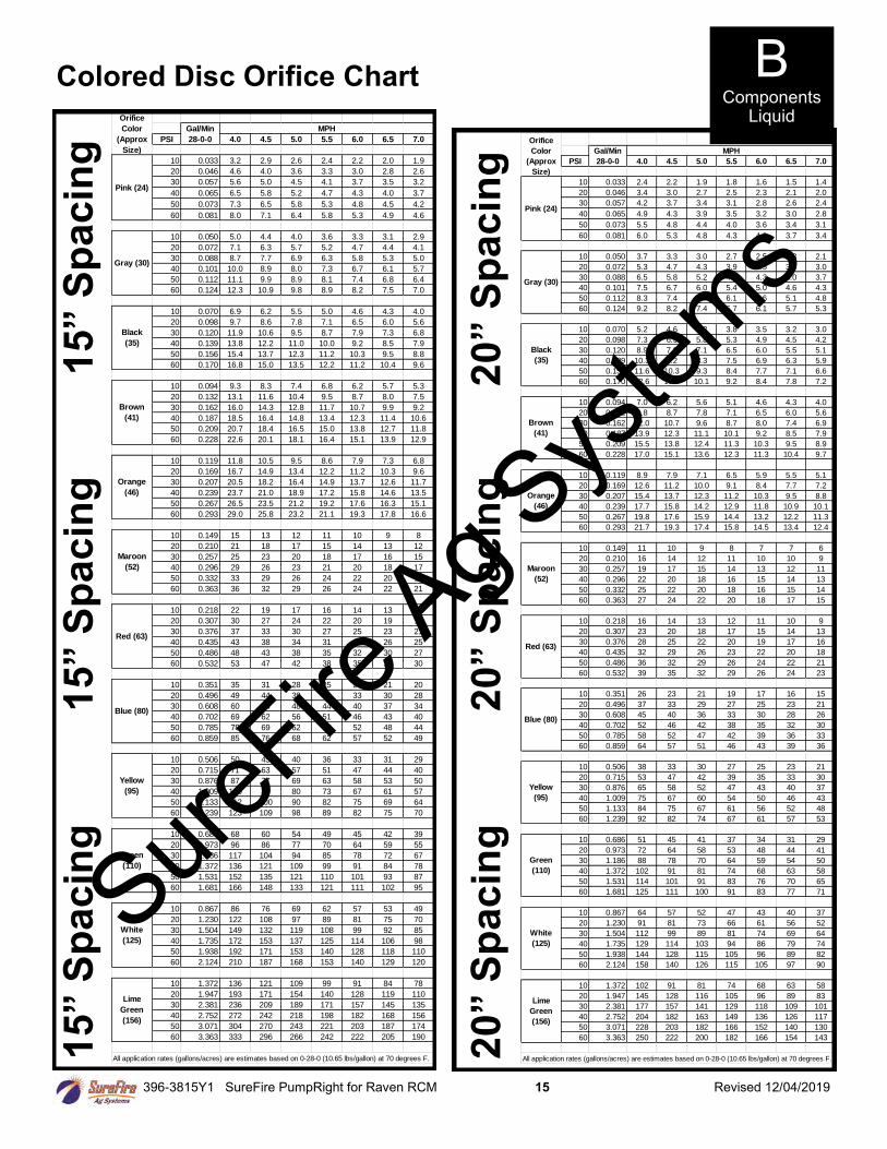
Colored Disc Orifice Chart 1
5” S
pa
cin
g
1
5” S
pa
cin
g
15
” S
pa
cin
g PSI 4.0 4.5 5.0 5.5 6.0 6.5 7.0
10 0.033 3.2 2.9 2.6 2.4 2.2 2.0 1.9
20 0.046 4.6 4.0 3.6 3.3 3.0 2.8 2.6
30 0.057 5.6 5.0 4.5 4.1 3.7 3.5 3.2
40 0.065 6.5 5.8 5.2 4.7 4.3 4.0 3.7
50 0.073 7.3 6.5 5.8 5.3 4.8 4.5 4.2
60 0.081 8.0 7.1 6.4 5.8 5.3 4.9 4.6
10 0.050 5.0 4.4 4.0 3.6 3.3 3.1 2.9
20 0.072 7.1 6.3 5.7 5.2 4.7 4.4 4.1
30 0.088 8.7 7.7 6.9 6.3 5.8 5.3 5.0
40 0.101 10.0 8.9 8.0 7.3 6.7 6.1 5.7
50 0.112 11.1 9.9 8.9 8.1 7.4 6.8 6.4
60 0.124 12.3 10.9 9.8 8.9 8.2 7.5 7.0
10 0.070 6.9 6.2 5.5 5.0 4.6 4.3 4.0
20 0.098 9.7 8.6 7.8 7.1 6.5 6.0 5.6
30 0.120 11.9 10.6 9.5 8.7 7.9 7.3 6.8
40 0.139 13.8 12.2 11.0 10.0 9.2 8.5 7.9
50 0.156 15.4 13.7 12.3 11.2 10.3 9.5 8.8
60 0.170 16.8 15.0 13.5 12.2 11.2 10.4 9.6
10 0.094 9.3 8.3 7.4 6.8 6.2 5.7 5.3
20 0.132 13.1 11.6 10.4 9.5 8.7 8.0 7.5
30 0.162 16.0 14.3 12.8 11.7 10.7 9.9 9.2
40 0.187 18.5 16.4 14.8 13.4 12.3 11.4 10.6
50 0.209 20.7 18.4 16.5 15.0 13.8 12.7 11.8
60 0.228 22.6 20.1 18.1 16.4 15.1 13.9 12.9
10 0.119 11.8 10.5 9.5 8.6 7.9 7.3 6.8
20 0.169 16.7 14.9 13.4 12.2 11.2 10.3 9.6
30 0.207 20.5 18.2 16.4 14.9 13.7 12.6 11.7
40 0.239 23.7 21.0 18.9 17.2 15.8 14.6 13.5
50 0.267 26.5 23.5 21.2 19.2 17.6 16.3 15.1
60 0.293 29.0 25.8 23.2 21.1 19.3 17.8 16.6
10 0.149 15 13 12 11 10 9 8
20 0.210 21 18 17 15 14 13 12
30 0.257 25 23 20 18 17 16 15
40 0.296 29 26 23 21 20 18 17
50 0.332 33 29 26 24 22 20 19
60 0.363 36 32 29 26 24 22 21
10 0.218 22 19 17 16 14 13 12
20 0.307 30 27 24 22 20 19 17
30 0.376 37 33 30 27 25 23 21
40 0.435 43 38 34 31 29 26 25
50 0.486 48 43 38 35 32 30 27
60 0.532 53 47 42 38 35 32 30
10 0.351 35 31 28 25 23 21 20
20 0.496 49 44 39 36 33 30 28
30 0.608 60 54 48 44 40 37 34
40 0.702 69 62 56 51 46 43 40
50 0.785 78 69 62 57 52 48 44
60 0.859 85 76 68 62 57 52 49
10 0.506 50 45 40 36 33 31 29
20 0.715 71 63 57 51 47 44 40
30 0.876 87 77 69 63 58 53 50
40 1.009 100 89 80 73 67 61 57
50 1.133 112 100 90 82 75 69 64
60 1.239 123 109 98 89 82 75 70
10 0.686 68 60 54 49 45 42 39
20 0.973 96 86 77 70 64 59 55
30 1.186 117 104 94 85 78 72 67
40 1.372 136 121 109 99 91 84 78
50 1.531 152 135 121 110 101 93 87
60 1.681 166 148 133 121 111 102 95
10 0.867 86 76 69 62 57 53 49
20 1.230 122 108 97 89 81 75 70
30 1.504 149 132 119 108 99 92 85
40 1.735 172 153 137 125 114 106 98
50 1.938 192 171 153 140 128 118 110
60 2.124 210 187 168 153 140 129 120
10 1.372 136 121 109 99 91 84 78
20 1.947 193 171 154 140 128 119 110
30 2.381 236 209 189 171 157 145 135
40 2.752 272 242 218 198 182 168 156
50 3.071 304 270 243 221 203 187 174
60 3.363 333 296 266 242 222 205 190
All application rates (gallons/acres) are estimates based on 0-28-0 (10.65 lbs/gallon) at 70 degrees F.
Brown
(41)
Green
(110)
White
(125)
Lime
Green
(156)
Orange
(46)
Maroon
(52)
Red (63)
Blue (80)
Yellow
(95)
MPH
Pink (24)
Gray (30)
Black
(35)
Gal/Min
28-0-0
Orifice
Color
(Approx
Size)
PSI 4.0 4.5 5.0 5.5 6.0 6.5 7.0
10 0.033 2.4 2.2 1.9 1.8 1.6 1.5 1.4
20 0.046 3.4 3.0 2.7 2.5 2.3 2.1 2.0
30 0.057 4.2 3.7 3.4 3.1 2.8 2.6 2.4
40 0.065 4.9 4.3 3.9 3.5 3.2 3.0 2.8
50 0.073 5.5 4.8 4.4 4.0 3.6 3.4 3.1
60 0.081 6.0 5.3 4.8 4.3 4.0 3.7 3.4
10 0.050 3.7 3.3 3.0 2.7 2.5 2.3 2.1
20 0.072 5.3 4.7 4.3 3.9 3.5 3.3 3.0
30 0.088 6.5 5.8 5.2 4.7 4.3 4.0 3.7
40 0.101 7.5 6.7 6.0 5.4 5.0 4.6 4.3
50 0.112 8.3 7.4 6.7 6.1 5.6 5.1 4.8
60 0.124 9.2 8.2 7.4 6.7 6.1 5.7 5.3
10 0.070 5.2 4.6 4.2 3.8 3.5 3.2 3.0
20 0.098 7.3 6.5 5.8 5.3 4.9 4.5 4.2
30 0.120 8.9 7.9 7.1 6.5 6.0 5.5 5.1
40 0.139 10.3 9.2 8.3 7.5 6.9 6.3 5.9
50 0.156 11.6 10.3 9.3 8.4 7.7 7.1 6.6
60 0.170 12.6 11.2 10.1 9.2 8.4 7.8 7.2
10 0.094 7.0 6.2 5.6 5.1 4.6 4.3 4.0
20 0.132 9.8 8.7 7.8 7.1 6.5 6.0 5.6
30 0.162 12.0 10.7 9.6 8.7 8.0 7.4 6.9
40 0.187 13.9 12.3 11.1 10.1 9.2 8.5 7.9
50 0.209 15.5 13.8 12.4 11.3 10.3 9.5 8.9
60 0.228 17.0 15.1 13.6 12.3 11.3 10.4 9.7
10 0.119 8.9 7.9 7.1 6.5 5.9 5.5 5.1
20 0.169 12.6 11.2 10.0 9.1 8.4 7.7 7.2
30 0.207 15.4 13.7 12.3 11.2 10.3 9.5 8.8
40 0.239 17.7 15.8 14.2 12.9 11.8 10.9 10.1
50 0.267 19.8 17.6 15.9 14.4 13.2 12.2 11.3
60 0.293 21.7 19.3 17.4 15.8 14.5 13.4 12.4
10 0.149 11 10 9 8 7 7 6
20 0.210 16 14 12 11 10 10 9
30 0.257 19 17 15 14 13 12 11
40 0.296 22 20 18 16 15 14 13
50 0.332 25 22 20 18 16 15 14
60 0.363 27 24 22 20 18 17 15
10 0.218 16 14 13 12 11 10 9
20 0.307 23 20 18 17 15 14 13
30 0.376 28 25 22 20 19 17 16
40 0.435 32 29 26 23 22 20 18
50 0.486 36 32 29 26 24 22 21
60 0.532 39 35 32 29 26 24 23
10 0.351 26 23 21 19 17 16 15
20 0.496 37 33 29 27 25 23 21
30 0.608 45 40 36 33 30 28 26
40 0.702 52 46 42 38 35 32 30
50 0.785 58 52 47 42 39 36 33
60 0.859 64 57 51 46 43 39 36
10 0.506 38 33 30 27 25 23 21
20 0.715 53 47 42 39 35 33 30
30 0.876 65 58 52 47 43 40 37
40 1.009 75 67 60 54 50 46 43
50 1.133 84 75 67 61 56 52 48
60 1.239 92 82 74 67 61 57 53
10 0.686 51 45 41 37 34 31 29
20 0.973 72 64 58 53 48 44 41
30 1.186 88 78 70 64 59 54 50
40 1.372 102 91 81 74 68 63 58
50 1.531 114 101 91 83 76 70 65
60 1.681 125 111 100 91 83 77 71
10 0.867 64 57 52 47 43 40 37
20 1.230 91 81 73 66 61 56 52
30 1.504 112 99 89 81 74 69 64
40 1.735 129 114 103 94 86 79 74
50 1.938 144 128 115 105 96 89 82
60 2.124 158 140 126 115 105 97 90
10 1.372 102 91 81 74 68 63 58
20 1.947 145 128 116 105 96 89 83
30 2.381 177 157 141 129 118 109 101
40 2.752 204 182 163 149 136 126 117
50 3.071 228 203 182 166 152 140 130
60 3.363 250 222 200 182 166 154 143
All application rates (gallons/acres) are estimates based on 0-28-0 (10.65 lbs/gallon) at 70 degrees F.
Brown
(41)
Green
(110)
White
(125)
Lime
Green
(156)
Orange
(46)
Maroon
(52)
Red (63)
Blue (80)
Yellow
(95)
MPH
Pink (24)
Gray (30)
Black
(35)
Gal/Min
28-0-0
Orifice
Color
(Approx
Size)
20
” S
pa
cin
g
2
0” S
pa
cin
g
2
0” S
pa
cin
g
B Components
Liquid
SureFire
Ag Sys
tems
396-3815Y1 SureFire PumpRight for Raven RCM 16 Revised 12/04/2019
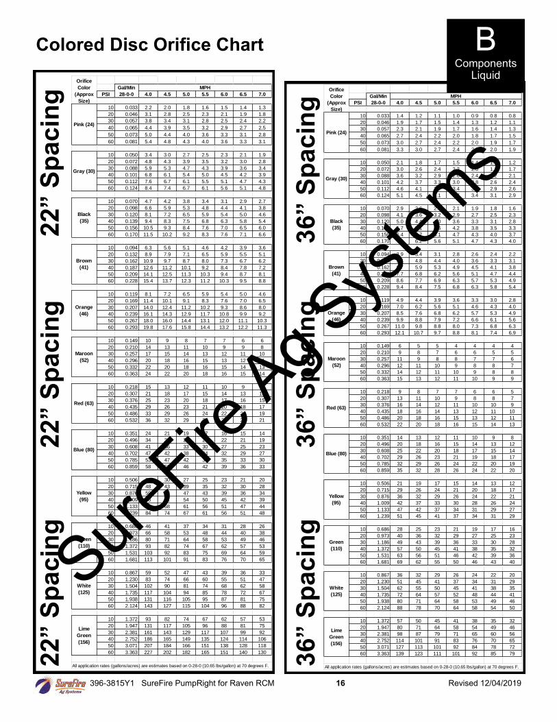
Colored Disc Orifice Chart 2
2” S
pa
cin
g
2
2” S
pa
cin
g
22
” S
pa
cin
g
36
” S
pa
cin
g
3
6” S
pa
cin
g
3
6” S
pa
cin
g PSI 4.0 4.5 5.0 5.5 6.0 6.5 7.0
10 0.033 2.2 2.0 1.8 1.6 1.5 1.4 1.3
20 0.046 3.1 2.8 2.5 2.3 2.1 1.9 1.8
30 0.057 3.8 3.4 3.1 2.8 2.5 2.4 2.2
40 0.065 4.4 3.9 3.5 3.2 2.9 2.7 2.5
50 0.073 5.0 4.4 4.0 3.6 3.3 3.1 2.8
60 0.081 5.4 4.8 4.3 4.0 3.6 3.3 3.1
10 0.050 3.4 3.0 2.7 2.5 2.3 2.1 1.9
20 0.072 4.8 4.3 3.9 3.5 3.2 3.0 2.8
30 0.088 5.9 5.3 4.7 4.3 3.9 3.6 3.4
40 0.101 6.8 6.1 5.4 5.0 4.5 4.2 3.9
50 0.112 7.6 6.7 6.1 5.5 5.1 4.7 4.3
60 0.124 8.4 7.4 6.7 6.1 5.6 5.1 4.8
10 0.070 4.7 4.2 3.8 3.4 3.1 2.9 2.7
20 0.098 6.6 5.9 5.3 4.8 4.4 4.1 3.8
30 0.120 8.1 7.2 6.5 5.9 5.4 5.0 4.6
40 0.139 9.4 8.3 7.5 6.8 6.3 5.8 5.4
50 0.156 10.5 9.3 8.4 7.6 7.0 6.5 6.0
60 0.170 11.5 10.2 9.2 8.3 7.6 7.1 6.6
10 0.094 6.3 5.6 5.1 4.6 4.2 3.9 3.6
20 0.132 8.9 7.9 7.1 6.5 5.9 5.5 5.1
30 0.162 10.9 9.7 8.7 8.0 7.3 6.7 6.2
40 0.187 12.6 11.2 10.1 9.2 8.4 7.8 7.2
50 0.209 14.1 12.5 11.3 10.3 9.4 8.7 8.1
60 0.228 15.4 13.7 12.3 11.2 10.3 9.5 8.8
10 0.119 8.1 7.2 6.5 5.9 5.4 5.0 4.6
20 0.169 11.4 10.1 9.1 8.3 7.6 7.0 6.5
30 0.207 14.0 12.4 11.2 10.2 9.3 8.6 8.0
40 0.239 16.1 14.3 12.9 11.7 10.8 9.9 9.2
50 0.267 18.0 16.0 14.4 13.1 12.0 11.1 10.3
60 0.293 19.8 17.6 15.8 14.4 13.2 12.2 11.3
10 0.149 10 9 8 7 7 6 6
20 0.210 14 13 11 10 9 9 8
30 0.257 17 15 14 13 12 11 10
40 0.296 20 18 16 15 13 12 11
50 0.332 22 20 18 16 15 14 13
60 0.363 24 22 20 18 16 15 14
10 0.218 15 13 12 11 10 9 8
20 0.307 21 18 17 15 14 13 12
30 0.376 25 23 20 18 17 16 15
40 0.435 29 26 23 21 20 18 17
50 0.486 33 29 26 24 22 20 19
60 0.532 36 32 29 26 24 22 21
10 0.351 24 21 19 17 16 15 14
20 0.496 34 30 27 24 22 21 19
30 0.608 41 36 33 30 27 25 23
40 0.702 47 42 38 34 32 29 27
50 0.785 53 47 42 39 35 33 30
60 0.859 58 52 46 42 39 36 33
10 0.506 34 30 27 25 23 21 20
20 0.715 48 43 39 35 32 30 28
30 0.876 59 53 47 43 39 36 34
40 1.009 68 61 54 50 45 42 39
50 1.133 76 68 61 56 51 47 44
60 1.239 84 74 67 61 56 51 48
10 0.686 46 41 37 34 31 28 26
20 0.973 66 58 53 48 44 40 38
30 1.186 80 71 64 58 53 49 46
40 1.372 93 82 74 67 62 57 53
50 1.531 103 92 83 75 69 64 59
60 1.681 113 101 91 83 76 70 65
10 0.867 59 52 47 43 39 36 33
20 1.230 83 74 66 60 55 51 47
30 1.504 102 90 81 74 68 62 58
40 1.735 117 104 94 85 78 72 67
50 1.938 131 116 105 95 87 81 75
60 2.124 143 127 115 104 96 88 82
10 1.372 93 82 74 67 62 57 53
20 1.947 131 117 105 96 88 81 75
30 2.381 161 143 129 117 107 99 92
40 2.752 186 165 149 135 124 114 106
50 3.071 207 184 166 151 138 128 118
60 3.363 227 202 182 165 151 140 130
All application rates (gallons/acres) are estimates based on 0-28-0 (10.65 lbs/gallon) at 70 degrees F.
Brown
(41)
Green
(110)
White
(125)
Lime
Green
(156)
Orange
(46)
Maroon
(52)
Red (63)
Blue (80)
Yellow
(95)
MPH
Pink (24)
Gray (30)
Black
(35)
Gal/Min
28-0-0
Orifice
Color
(Approx
Size) PSI 4.0 4.5 5.0 5.5 6.0 6.5 7.0
10 0.033 1.4 1.2 1.1 1.0 0.9 0.8 0.8
20 0.046 1.9 1.7 1.5 1.4 1.3 1.2 1.1
30 0.057 2.3 2.1 1.9 1.7 1.6 1.4 1.3
40 0.065 2.7 2.4 2.2 2.0 1.8 1.7 1.5
50 0.073 3.0 2.7 2.4 2.2 2.0 1.9 1.7
60 0.081 3.3 3.0 2.7 2.4 2.2 2.0 1.9
10 0.050 2.1 1.8 1.7 1.5 1.4 1.3 1.2
20 0.072 3.0 2.6 2.4 2.2 2.0 1.8 1.7
30 0.088 3.6 3.2 2.9 2.6 2.4 2.2 2.1
40 0.101 4.2 3.7 3.3 3.0 2.8 2.6 2.4
50 0.112 4.6 4.1 3.7 3.4 3.1 2.9 2.6
60 0.124 5.1 4.5 4.1 3.7 3.4 3.1 2.9
10 0.070 2.9 2.6 2.3 2.1 1.9 1.8 1.6
20 0.098 4.1 3.6 3.2 2.9 2.7 2.5 2.3
30 0.120 5.0 4.4 4.0 3.6 3.3 3.1 2.8
40 0.139 5.7 5.1 4.6 4.2 3.8 3.5 3.3
50 0.156 6.4 5.7 5.1 4.7 4.3 4.0 3.7
60 0.170 7.0 6.2 5.6 5.1 4.7 4.3 4.0
10 0.094 3.9 3.4 3.1 2.8 2.6 2.4 2.2
20 0.132 5.4 4.8 4.4 4.0 3.6 3.3 3.1
30 0.162 6.7 5.9 5.3 4.9 4.5 4.1 3.8
40 0.187 7.7 6.8 6.2 5.6 5.1 4.7 4.4
50 0.209 8.6 7.7 6.9 6.3 5.7 5.3 4.9
60 0.228 9.4 8.4 7.5 6.8 6.3 5.8 5.4
10 0.119 4.9 4.4 3.9 3.6 3.3 3.0 2.8
20 0.169 7.0 6.2 5.6 5.1 4.6 4.3 4.0
30 0.207 8.5 7.6 6.8 6.2 5.7 5.3 4.9
40 0.239 9.9 8.8 7.9 7.2 6.6 6.1 5.6
50 0.267 11.0 9.8 8.8 8.0 7.3 6.8 6.3
60 0.293 12.1 10.7 9.7 8.8 8.1 7.4 6.9
10 0.149 6 5 5 4 4 4 4
20 0.210 9 8 7 6 6 5 5
30 0.257 11 9 8 8 7 7 6
40 0.296 12 11 10 9 8 8 7
50 0.332 14 12 11 10 9 8 8
60 0.363 15 13 12 11 10 9 9
10 0.218 9 8 7 7 6 6 5
20 0.307 13 11 10 9 8 8 7
30 0.376 16 14 12 11 10 10 9
40 0.435 18 16 14 13 12 11 10
50 0.486 20 18 16 15 13 12 11
60 0.532 22 20 18 16 15 14 13
10 0.351 14 13 12 11 10 9 8
20 0.496 20 18 16 15 14 13 12
30 0.608 25 22 20 18 17 15 14
40 0.702 29 26 23 21 19 18 17
50 0.785 32 29 26 24 22 20 19
60 0.859 35 32 28 26 24 22 20
10 0.506 21 19 17 15 14 13 12
20 0.715 29 26 24 21 20 18 17
30 0.876 36 32 29 26 24 22 21
40 1.009 42 37 33 30 28 26 24
50 1.133 47 42 37 34 31 29 27
60 1.239 51 45 41 37 34 31 29
10 0.686 28 25 23 21 19 17 16
20 0.973 40 36 32 29 27 25 23
30 1.186 49 43 39 36 33 30 28
40 1.372 57 50 45 41 38 35 32
50 1.531 63 56 51 46 42 39 36
60 1.681 69 62 55 50 46 43 40
10 0.867 36 32 29 26 24 22 20
20 1.230 51 45 41 37 34 31 29
30 1.504 62 55 50 45 41 38 35
40 1.735 72 64 57 52 48 44 41
50 1.938 80 71 64 58 53 49 46
60 2.124 88 78 70 64 58 54 50
10 1.372 57 50 45 41 38 35 32
20 1.947 80 71 64 58 54 49 46
30 2.381 98 87 79 71 65 60 56
40 2.752 114 101 91 83 76 70 65
50 3.071 127 113 101 92 84 78 72
60 3.363 139 123 111 101 92 85 79
All application rates (gallons/acres) are estimates based on 0-28-0 (10.65 lbs/gallon) at 70 degrees F.
Brown
(41)
Green
(110)
White
(125)
Lime
Green
(156)
Orange
(46)
Maroon
(52)
Red (63)
Blue (80)
Yellow
(95)
MPH
Pink (24)
Gray (30)
Black
(35)
Gal/Min
28-0-0
Orifice
Color
(Approx
Size)
B Components
Liquid
SureFire
Ag Sys
tems

396-3815Y1 SureFire PumpRight for Raven RCM 17 Revised 12/04/2019
SureFire
Ag Sys
tems
396-3815Y1 SureFire PumpRight for Raven RCM 18 Revised 12/04/2019
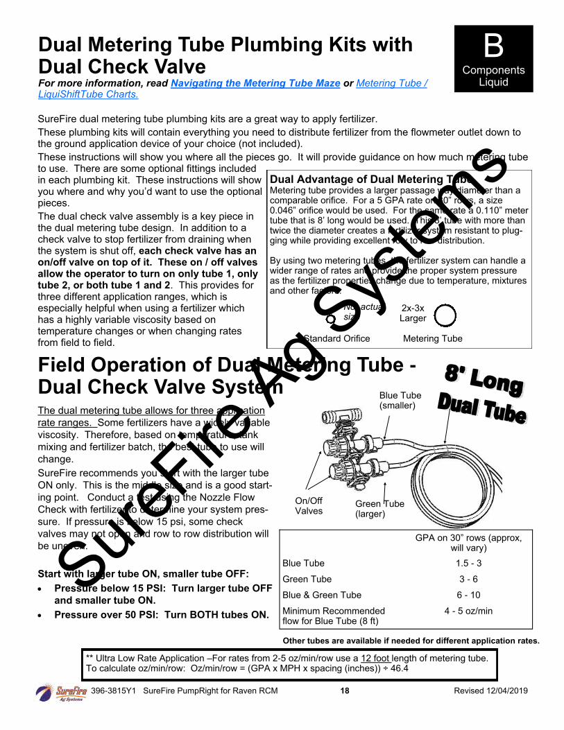
Dual Metering Tube Plumbing Kits with Dual Check Valve For more information, read Navigating the Metering Tube Maze or Metering Tube / LiquiShiftTube Charts.
SureFire dual metering tube plumbing kits are a great way to apply fertilizer.
These plumbing kits will contain everything you need to distribute fertilizer from the flowmeter outlet down to the ground application device of your choice (not included).
These instructions will show you where all the pieces go. It will provide guidance on how much metering tube to use. There are some optional fittings included in each plumbing kit. These instructions will show you where and why you’d want to use the optional pieces.
The dual check valve assembly is a key piece in the dual metering tube design. In addition to a check valve to stop fertilizer from draining when the system is shut off, each check valve has an on/off valve on top of it. These on / off valves allow the operator to turn on only tube 1, only tube 2, or both tube 1 and 2. This provides for three different application ranges, which is especially helpful when using a fertilizer which has a highly variable viscosity based on temperature changes or when changing rates from field to field.
Dual Advantage of Dual Metering Tube Metering tube provides a larger passage way diameter than a comparable orifice. For a 5 GPA rate on 30” rows, a size 0.046” orifice would be used. For the same rate a 0.110” meter tube that is 8’ long would be used. This 8’ tube with more than twice the diameter creates a fertilizer system resistant to plug-ging while providing excellent row to row distribution. By using two metering tubes, the fertilizer system can handle a wider range of rates and provide the proper system pressure as the fertilizer properties change due to temperature, mixtures and other factors.
Standard Orifice Metering Tube
2x-3x Larger
The dual metering tube allows for three application
rate ranges. Some fertilizers have a widely variable
viscosity. Therefore, based on temperature, tank
mixing and fertilizer batch, the best tube to use will
change.
SureFire recommends you start with the larger tube
ON only. This is the middle size and is a good start-
ing point. Conduct a test using the Nozzle Flow
Check with fertilizer to determine your system pres-
sure. If pressure is below 15 psi, some check
valves may not open and row to row distribution will
be uneven.
Start with larger tube ON, smaller tube OFF:
• Pressure below 15 PSI: Turn larger tube OFF
and smaller tube ON.
• Pressure over 50 PSI: Turn BOTH tubes ON.
Field Operation of Dual Metering Tube - Dual Check Valve System
Blue Tube (smaller)
Green Tube (larger)
GPA on 30” rows (approx, will vary)
Blue Tube 1.5 - 3
Green Tube 3 - 6
Blue & Green Tube 6 - 10
Minimum Recommended flow for Blue Tube (8 ft)
4 - 5 oz/min
** Ultra Low Rate Application –For rates from 2-5 oz/min/row use a 12 foot length of metering tube. To calculate oz/min/row: Oz/min/row = (GPA x MPH x spacing (inches)) ÷ 46.4
On/Off Valves
B Components
Liquid
Other tubes are available if needed for different application rates.
Not actual size
SureFire
Ag Sys
tems
396-3815Y1 SureFire PumpRight for Raven RCM 19 Revised 12/04/2019
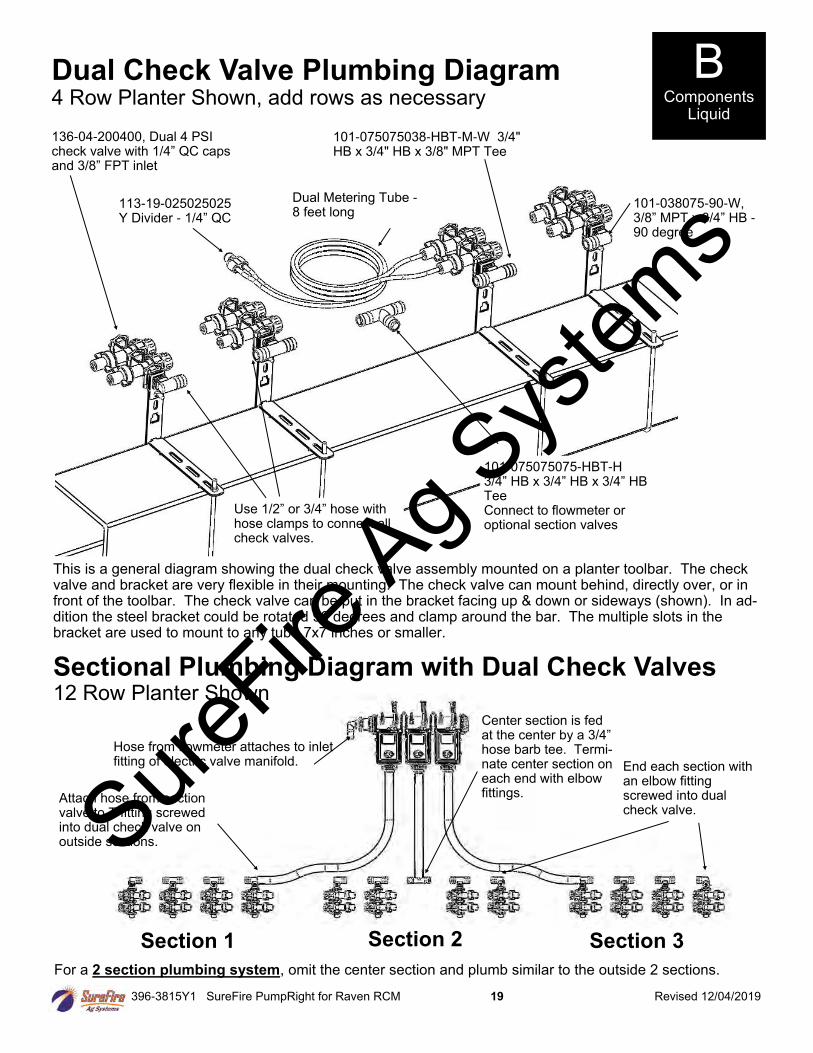
Dual Check Valve Plumbing Diagram 4 Row Planter Shown, add rows as necessary
136-04-200400, Dual 4 PSI check valve with 1/4” QC caps and 3/8” FPT inlet
101-038075-90-W, 3/8” MPT x 3/4” HB - 90 degree
101-075075075-HBT-H 3/4” HB x 3/4” HB x 3/4” HB Tee Connect to flowmeter or optional section valves
101-075075038-HBT-M-W 3/4" HB x 3/4" HB x 3/8" MPT Tee
This is a general diagram showing the dual check valve assembly mounted on a planter toolbar. The check valve and bracket are very flexible in their mounting. The check valve can mount behind, directly over, or in front of the toolbar. The check valve can be put in the bracket facing up & down or sideways (shown). In ad-dition the steel bracket could be rotated 90 degrees and clamp around the bar. The multiple slots in the bracket are used to mount to any tube 7x7 inches or smaller.
113-19-025025025 Y Divider - 1/4” QC
Dual Metering Tube - 8 feet long
Use 1/2” or 3/4” hose with hose clamps to connect all check valves.
Sectional Plumbing Diagram with Dual Check Valves 12 Row Planter Shown
End each section with an elbow fitting screwed into dual check valve.
Section 1
Attach hose from section valve to T fitting screwed into dual check valve on outside sections.
For a 2 section plumbing system, omit the center section and plumb similar to the outside 2 sections.
Section 2 Section 3
Center section is fed at the center by a 3/4” hose barb tee. Termi-nate center section on each end with elbow fittings.
Hose from flowmeter attaches to inlet fitting of electric valve manifold.
B Components
Liquid
SureFire
Ag Sys
tems
396-3815Y1 SureFire PumpRight for Raven RCM 20 Revised 12/04/2019
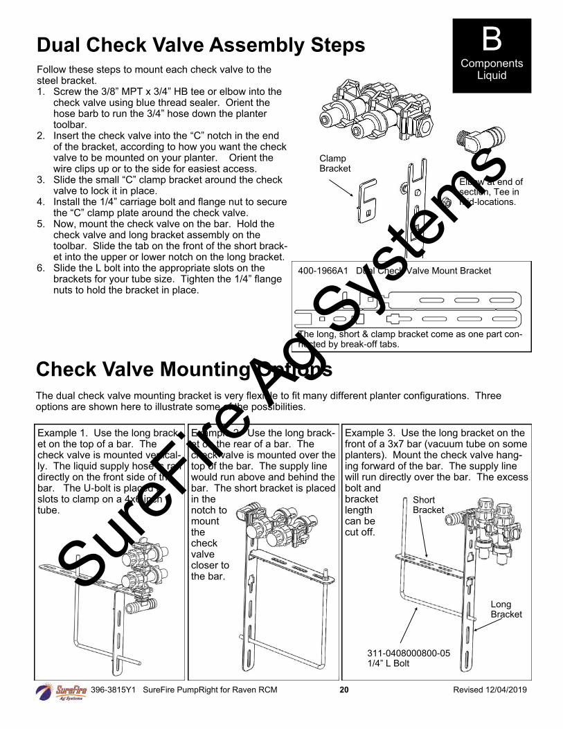
Dual Check Valve Assembly Steps Follow these steps to mount each check valve to the steel bracket. 1. Screw the 3/8” MPT x 3/4” HB tee or elbow into the
check valve using blue thread sealer. Orient the hose barb to run the 3/4” hose down the planter toolbar.
2. Insert the check valve into the “C” notch in the end of the bracket, according to how you want the check valve to be mounted on your planter. Orient the wire clips up or to the side for easiest access.
3. Slide the small “C” clamp bracket around the check valve to lock it in place.
4. Install the 1/4” carriage bolt and flange nut to secure the “C” clamp plate around the check valve.
5. Now, mount the check valve on the bar. Hold the check valve and long bracket assembly on the toolbar. Slide the tab on the front of the short brack-et into the upper or lower notch on the long bracket.
6. Slide the L bolt into the appropriate slots on the brackets for your tube size. Tighten the 1/4” flange nuts to hold the bracket in place.
Clamp Bracket
400-1966A1 Dual Check Valve Mount Bracket
The long, short & clamp bracket come as one part con-nected by break-off tabs.
Elbow at end of section, Tee in mid-locations.
Check Valve Mounting Options
The dual check valve mounting bracket is very flexible to fit many different planter configurations. Three options are shown here to illustrate some of the possibilities.
Example 1. Use the long brack-et on the top of a bar. The check valve is mounted vertical-ly. The liquid supply hose is ran directly on the front side of the bar. The U-bolt is placed in slots to clamp on a 4x6 inch tube.
Example 2. Use the long brack-et on the rear of a bar. The check valve is mounted over the top of the bar. The supply line would run above and behind the bar. The short bracket is placed in the notch to mount the check valve closer to the bar.
Example 3. Use the long bracket on the front of a 3x7 bar (vacuum tube on some planters). Mount the check valve hang-ing forward of the bar. The supply line will run directly over the bar. The excess bolt and bracket length can be cut off.
311-0408000800-05 1/4” L Bolt
Short Bracket
Long Bracket
B Components
Liquid
SureFire
Ag Sys
tems
396-3815Y1 SureFire PumpRight for Raven RCM 21 Revised 12/04/2019
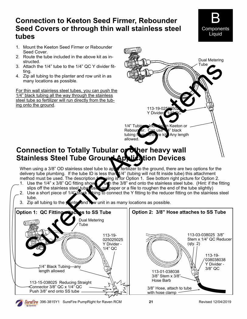
Connection to Keeton Seed Firmer, Rebounder Seed Covers or through thin wall stainless steel tubes
1. Mount the Keeton Seed Firmer or Rebounder Seed Cover.
2. Route the tube included in the above kit as in-structed.
3. Attach the 1/4” tube to the 1/4” QC Y divider fit-ting.
4. Zip all tubing to the planter and row unit in as many locations as possible.
For thin wall stainless steel tubes, you can push the 1/4” black tubing all the way through the stainless steel tube so fertilizer will run directly from the tub-ing onto the ground.
1/4” Tubing—Included in Keeton or Rebounder. Can use 1/4” black tubing from SureFire kit. Any length allowed.
113-19-025025025 Y Divider - 1/4” QC
Dual Metering Tube
Option 1: QC Fitting attaches to SS Tube
113-15-038025 Reducing Straight Connector 3/8” QC x 1/4” QC Push 3/8” end onto SS tube
Connection to Totally Tubular or other heavy wall Stainless Steel Tube Ground Application Devices
Dual Metering Tube
1/4” Black Tubing—any length allowed
113-19-025025025 Y Divider - 1/4” QC
113-19-038038038 Y Divider - 3/8” QC
Option 2: 3/8” Hose attaches to SS Tube
113-03-038025 3/8” Stem x 1/4” QC Reducer (qty. 2)
113-01-038038 3/8” Stem x 3/8” Hose Barb
3/8” Hose, attach to tube with hose clamp
B Components
Liquid
When using a 3/8” OD stainless steel tube to apply fertilizer to the ground, there are two options for the delivery tube plumbing. If the tube ID is less than 1/4” (tubing will not fit inside tube) this attachment method must be used. The description following is for Option 1. See bottom right picture for Option 2. 1. Use the 1/4” x 3/8” QC fitting shown. Push the 3/8” end onto the stainless steel tube. (Hint: if the fitting
slips off the stainless steel tube, use sandpaper or a file to roughen the end of the tube slightly) 2. Use a short piece of 1/4” black tubing to connect the Y fitting to the reducer fitting on the stainless steel
tube. 3. Zip all tubing to the planter and row unit in as many locations as possible.
SureFire
Ag Sys
tems
396-3815Y1 SureFire PumpRight for Raven RCM 22 Revised 12/04/2019
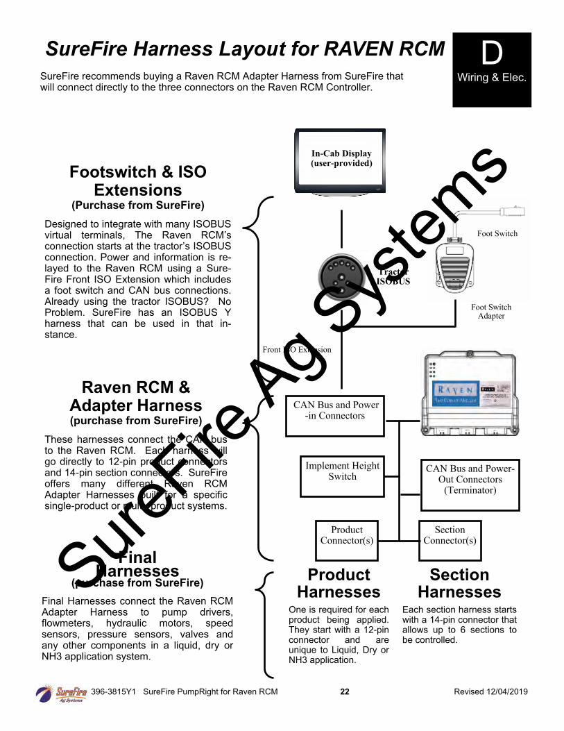
SureFire recommends buying a Raven RCM Adapter Harness from SureFire that will connect directly to the three connectors on the Raven RCM Controller.
D Wiring & Elec.
SureFire Harness Layout for RAVEN RCM
Footswitch & ISO Extensions
(Purchase from SureFire)
Designed to integrate with many ISOBUS virtual terminals, The Raven RCM’s connection starts at the tractor’s ISOBUS connection. Power and information is re-layed to the Raven RCM using a Sure-Fire Front ISO Extension which includes a foot switch and CAN bus connections. Already using the tractor ISOBUS? No Problem. SureFire has an ISOBUS Y harness that can be used in that in-stance.
Final Harnesses
(purchase from SureFire) Final Harnesses connect the Raven RCM Adapter Harness to pump drivers, flowmeters, hydraulic motors, speed sensors, pressure sensors, valves and any other components in a liquid, dry or NH3 application system.
Product Harnesses
One is required for each product being applied. They start with a 12-pin connector and are unique to Liquid, Dry or NH3 application.
Section Harnesses
Each section harness starts with a 14-pin connector that allows up to 6 sections to be controlled.
Raven RCM & Adapter Harness (purchase from SureFire)
These harnesses connect the CAN bus to the Raven RCM. Each harness will go directly to 12-pin product connectors and 14-pin section connectors. SureFire offers many different Raven RCM Adapter Harnesses built for a specific single-product or multi- product systems.
In-Cab Display (user-provided)
Foot Switch
CAN Bus and Power-in Connectors
CAN Bus and Power-Out Connectors
(Terminator)
Implement Height Switch
Product Connector(s)
Section Connector(s)
Foot Switch Adapter
Front ISO Extension
Tractor ISOBUS
SureFire
Ag Sys
tems
396-3815Y1 SureFire PumpRight for Raven RCM 23 Revised 12/04/2019
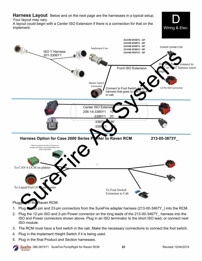
Master SwitchConnector
POWER CONNECTOR
12 Pin ISO Connector
214-00-3553Y1 - 10' 214-00-3554Y1 - 20'214-00-3555Y1 - 30'214-00-3556Y1 - 40'214-00-3557Y1 - 50'
Implement Con-
Harness Layout Below and on the next page are the harnesses in a typical setup. Your layout may vary. A layout could begin with a Center ISO Extension if there is a connection for that on the implement.
ISO Y Harness 201-3306Y1
Front ISO Extension
Connect to Foot Switch Adapter harness that goes to foot switch in cab
Center ISO Extension
206-14-3385Y1 10’
-3386Y1 20’
-3387Y1 30’
-3388Y1 40’
1'
1'
1'
1'
1'
2'
Attach connector for this to harness so jumper on planter can be kept safely here.
DT04-12SC-B016
When using this harness, change fuses on RCM Main Adapter Harness from 15 Amps to 7.5 Amps (QTY 2) and from 25 Amps to 15 Amps (QTY 1).
Plugging in the Raven RCM:
1. Plug the 35-pin and 23-pin connectors from the SureFire adapter harness (213-00-3467Y_) into the RCM.
2. Plug the 12-pin ISO and 2-pin Power connector on the long leads of the 213-00-3467Y_ harness into the
ISO and Power connectors shown above. Plug in an ISO terminator to the short ISO lead, or connect next
ISO module.
3. The RCM must have a foot switch in the cab. Make the necessary connections to connect the foot switch.
4. Plug in the Implement Height Switch if it is being used.
5. Plug in the final Product and Section harnesses.
Harness Option for Case 2000 Series Planter to Raven RCM 213-05-3873Y_
To Liquid Fert UCM on planter
To CAN 4 UCM on planter
To Foot Switch Extension to Cab
ISO and Power connect to 3417 or -3467 harness (next pages)
D Wiring & Elec.
SureFire
Ag Sys
tems
396-3815Y1 SureFire PumpRight for Raven RCM 24 Revised 12/04/2019
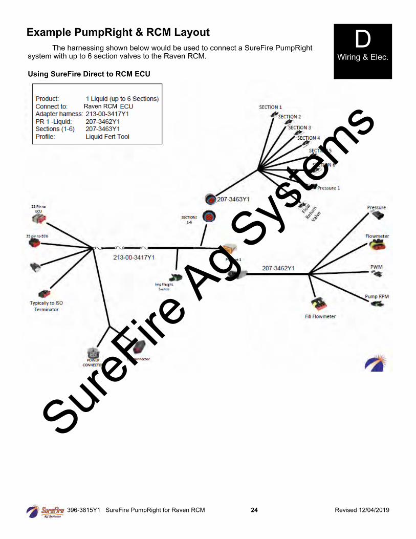
Example PumpRight & RCM Layout
The harnessing shown below would be used to connect a SureFire PumpRight system with up to 6 section valves to the Raven RCM.
D Wiring & Elec.
Using SureFire Direct to RCM ECU
Raven RCM
SureFire
Ag Sys
tems

396-3815Y1 SureFire PumpRight for Raven RCM 25 Revised 12/04/2019
D Wiring
SureFire
Ag Sys
tems
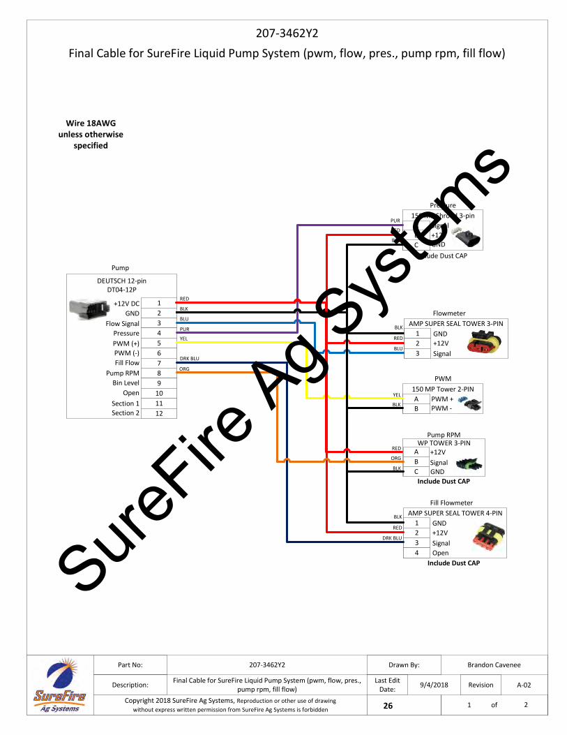
Wire 18AWG unless otherwise
specified
Final Cable for SureFire Liquid Pump System (pwm, flow, pres., pump rpm, fill flow)
207-3462Y2
9/4/2018
Brandon Cavenee207-3462Y2
Final Cable for SureFire Liquid Pump System (pwm, flow, pres., pump rpm, fill flow)
Part No:
Description:
Drawn By:
Last Edit Date:
Project:26Copyright 2018 SureFire Ag Systems, Reproduction or other use of drawingwithout express written permission from SureFire Ag Systems is forbidden
Revision
of
A-02
1 2
123456
+12V DC
Flow SignalGND
PressurePWM (+)PWM (-)
RED
BLK
BLU
PUR
YEL
DRK BLU
PWM
A150 MP Tower 2-PIN
BPWM +PWM -
YEL
BLK
Pressure
A150 MP Shroud 3-pin
BC
Signal+12VGND
PUR
RED
BLK
DEUTSCH 12-pin DT04-12P
Pump
78
Include Dust CAP
1 GND+12V
AMP SUPER SEAL TOWER 4-PINBLK
RED2
Fill Flowmeter
3 SignalDRK BLU
4 Open
ORGA
GND
+12VWP TOWER 3-PIN
BC
Signal
Pump RPM
RED
BLK
9101112
Fill FlowPump RPM
Bin LevelOpen
Section 1Section 2
Include Dust CAP
Include Dust CAP
ORG
1 GND+12V
AMP SUPER SEAL TOWER 3-PINBLK
RED2
Flowmeter
3 SignalBLU
SureFire
Ag Sys
tems
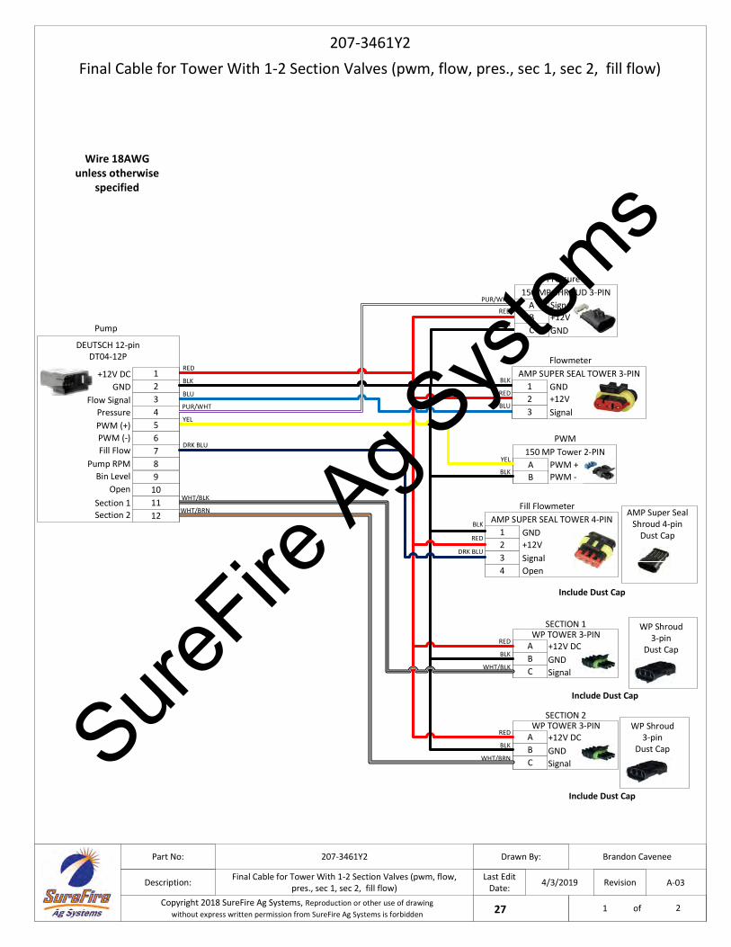
Wire 18AWG unless otherwise
specified
Final Cable for Tower With 1-2 Section Valves (pwm, flow, pres., sec 1, sec 2, fill flow)
207-3461Y2
4/3/2019
Brandon Cavenee207-3461Y2
Final Cable for Tower With 1-2 Section Valves (pwm, flow, pres., sec 1, sec 2, fill flow)
Part No:
Description:
Drawn By:
Last Edit Date:
Project:27Copyright 2018 SureFire Ag Systems, Reproduction or other use of drawingwithout express written permission from SureFire Ag Systems is forbidden
Revision
of
A-03
1 2
PWM
A150 MP Tower 2-PIN
BPWM +PWM -
YEL
BLK
78
BLKA
Signal
+12V DCWP TOWER 3-PIN
BC
GND
SECTION 2
RED
WHT/BRN
BLKA
Signal
+12V DCWP TOWER 3-PIN
BC
GND
SECTION 1
RED
WHT/BLK
PUR/WHT
RED
BLK
BLU
YEL
DRK BLU
123456
+12V DC
Flow SignalGND
PressurePWM (+)PWM (-)
DEUTSCH 12-pin DT04-12P
Pump
789
101112
Fill FlowPump RPM
Bin LevelOpen
Section 1Section 2
WHT/BLK
WHT/BRN
1 GND+12V
AMP SUPER SEAL TOWER 3-PINBLK
RED2
Flowmeter
3 SignalBLU
1 GND+12V
AMP SUPER SEAL TOWER 4-PINBLK
RED2
Fill Flowmeter
3 SignalDRK BLU
4 Open
Pressure
A150 MP SHROUD 3-PIN
BC
RED
BLK
Signal+12VGND
Include Dust Cap
PUR/WHT
WP Shroud3-pin
Dust Cap
WP Shroud3-pin
Dust Cap
AMP Super SealShroud 4-pin
Dust Cap
Include Dust Cap
Include Dust Cap
SureFire
Ag Sys
tems
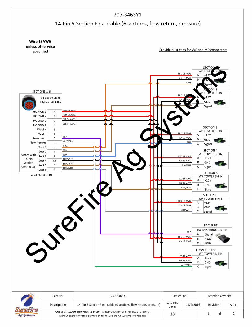
Wire 18AWG unless otherwise
specified
14-Pin 6-Section Final Cable (6 sections, flow return, pressure)207-3463Y1
11/2/2016
Brandon Cavenee207-3463Y1
14-Pin 6-Section Final Cable (6 sections, flow return, pressure)
Part No:
Description:
Drawn By:
Last Edit Date:
Project:28Copyright 2016 SureFire Ag Systems, Reproduction or other use of drawingwithout express written permission from SureFire Ag Systems is forbidden
Revision
of
A-01
1 2
BLK 18 AWGA
Signal
+12VWP TOWER 3-PIN
BC
GND
SECTION 6
RED 18 AWG
BLU/WHT
Provide dust caps for WP and MP connectors
A Signal+12V
150 MP SHROUD 3-PINPRP
RED 18 AWG B
PRESSURE
C GNDBLK 18 AWG
BLK 18 AWGA
Signal
+12VWP TOWER 3-PIN
BC
GND
FLOW RETURN
RED 18 AWG
WHT/GRN
BLK 18 AWGA
Signal
+12VWP TOWER 3-PIN
BC
GND
SECTION 5
RED 18 AWG
BRN/WHT
BLK 18 AWGA
Signal
+12VWP TOWER 3-PIN
BC
GND
SECTION 3
RED 18 AWG
BLU
BLK 18 AWGA
Signal
+12VWP TOWER 3-PIN
BC
GND
SECTION 2
RED 18 AWG
BRN
BLK 18 AWGA
Signal
+12VWP TOWER 3-PIN
BC
GND
SECTION 1
RED 18 AWG
ORG
DEFGHJKLMNP
Sect 3Sect 4Sect 5Sect 6
BRN
RED 14 AWG
BLK 14 AWG
ORG
BLU
BLK/WHT
SECTIONS 1-6
BRN/WHT
BLU/WHT
RED 14 AWG
Pressure Flow Return
PRP
WHT/GRN
14 pin Deutsch HDP26-18-14SE
Sect 2
C
Sect 1
BAHC PWR 1
HC PWR 2HC GND 1HC GND 2
PWM -PWM +
Label: Section IN
Mates with 14 Pin
Section Connector
BLK 14 AWG
BLK 18 AWGA
Signal
+12VWP TOWER 3-PIN
BC
GND
SECTION 4
RED 18 AWG
BLK/WHT
SureFire
Ag Sys
tems
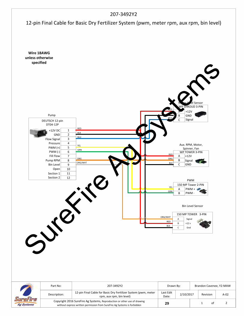
Wire 18AWG unless otherwise
specified
12‐pin Final Cable for Basic Dry Fertilizer System (pwm, meter rpm, aux rpm, bin level)
207‐3492Y2
2/10/2017
Brandon Cavenee, Y2‐MAW207‐3492Y2
12‐pin Final Cable for Basic Dry Fertilizer System (pwm, meter rpm, aux rpm, bin level)
Part No:
Description:
Drawn By:
Last Edit Date:
Project:29Copyright 2016 SureFire Ag Systems, Reproduction or other use of drawingwithout express written permission from SureFire Ag Systems is forbidden
Revision
of
A‐02
1 2
1
2
3
4
5
6
+12V DC
Flow Signal
GND
Pressure
PWM (+)
PWM (‐)
RED
BLK
BLU
YEL
PWM
A
150 MP Tower 2‐PIN
B
PWM +PWM ‐
YEL
GRN
Meter RPM Sensor
A
B
C
+12V
GNDSignal
RED
BLK
BLU
DEUTSCH 12‐pin DT04‐12P
Pump
7
8ORG
A
GND
+12VWP TOWER 3‐PIN
B
CSignal
Aux. RPM, Motor, Spinner, Fan
RED
BLK9
10
11
12
Fill Flow
Pump RPM
Bin Level
Open
Section 1
Section 2
GRN
ORG
WP SHROUD 3‐PIN
150 MP TOWER 3‐PIN
Bin Level Sensor
A Signal
B +12 v
C Gnd
ORG/WHT
ORG/WHT
RED
BLK
SureFire
Ag Sys
tems
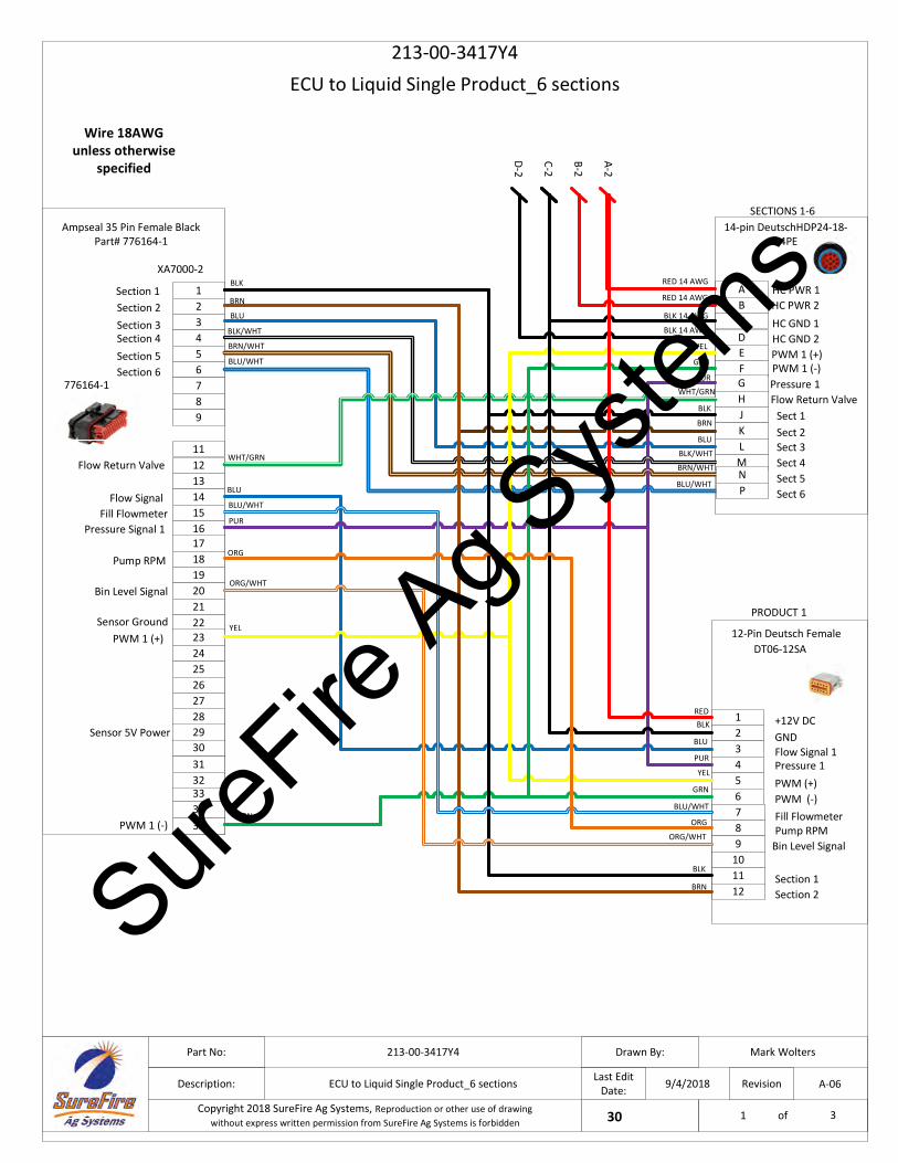
ECU to Liquid Single Product_6 sections
213-00-3417Y4
9/4/2018
Mark Wolters213-00-3417Y4
ECU to Liquid Single Product_6 sections
Part No:
Description:
Drawn By:
Last Edit Date:
Project:30Copyright 2018 SureFire Ag Systems, Reproduction or other use of drawingwithout express written permission from SureFire Ag Systems is forbidden
Revision
of
A-06
1 3
C-2
Wire 18AWG unless otherwise
specified
123456789
12131415161718192021
28
31
3334
11
32
Section 1
Pressure Signal 1
222324252627
3029
35
Flow Signal
PWM 1 (+)Sensor Ground
Sensor 5V Power123456
ABCDEFGHJKLM
+12V DC
Flow Signal 1GND
Pressure 1PWM (+)PWM (-)
Sect 1
Sect 3Sect 2
Sect 4Sect 5Sect 6
HC PWR 1HC PWR 2
PWM 1 (+)HC GND 2
RED
BRN
RED 14 AWG
BLK
BLK 14 AWG
BLK
BLU
BLU
PUR
YEL
GRN
BLK/WHT
PRODUCT 1
SECTIONS 1-6
BLU
YEL
BLK/WHT
BLK
PUR
12-Pin Deutsch Female
XA7000-2
Section 3Section 2
Section 4Section 5Section 6
BRN
BLU
BRN/WHT
BRN/WHT
BLU/WHT
BLU/WHT
RED 14 AWG
Pressure 1Flow Return Valve
PUR
A-2
B-2
D-2
BLK 14 AWG
WHT/GRN
WHT/GRN
Flow Return Valve
DT06-12SA
14-pin DeutschHDP24-18-14PE
Ampseal 35 Pin Female BlackPart# 776164-1
776164-1
NP
HC GND 1
PWM 1 (-)
789
101112
Fill FlowmeterPump RPM
Section 1Section 2
BLU/WHT
BLK
Pump RPM
Fill FlowmeterBLU/WHT
ORG
ORG
BRN
YEL
GRN
Bin Level Signal
Bin Level SignalORG/WHT
ORG/WHTPWM 1 (-)
GRN
SureFire
Ag Sys
tems
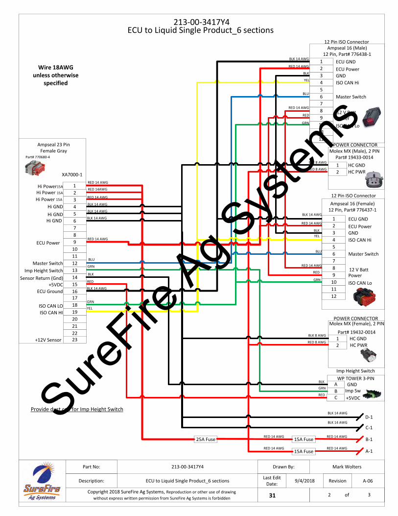
213-00-3417Y4
9/4/2018
Mark Wolters213-00-3417Y4
ECU to Liquid Single Product_6 sections
Part No:
Description:
Drawn By:
Last Edit Date:
Project:31Copyright 2018 SureFire Ag Systems, Reproduction or other use of drawingwithout express written permission from SureFire Ag Systems is forbidden
Revision
of
A-06
2 3
ECU to Liquid Single Product_6 sections
Wire 18AWG unless otherwise
specified
Ground12V Sensor Power
BLK 8 AWG
RED 8 AWG
RED
AImp Sw
WP TOWER 3-PIN
B+5VDC
Imp Height Switch
BLK
RED 14 AWG
BLK 14 AWG
RED 14 AWG
RED 14 AWG
RED 14 AWG
RED 14AWG
25A Fuse
15A Fuse
15A FuseRED 14 AWG
RED 14 AWG
RED 14 AWG
BLU
GRN
RED
BLK 14 AWG
RED 14 AWG
BLK
12
HC GNDHC PWR
BLK 8 AWG
RED 8 AWG
12 Pin ISO Connector
RED 14 AWG
D-1
C-1
B-1
A-1
BLK 14 AWG
BLK 14 AWG
BLK 14 AWG
BLK 14 AWG
BLK 14 AWG
3
ECU GND
GND
12
YEL456789
10
1211
ECU Power
ISO CAN Hi
Master Switch
12 V BattPowerISO CAN Lo
Ampseal 16 (Female)12 Pin, Part# 776437-1
12
HC GNDHC PWR
Molex MX (Female), 2 PIN
Part# 19432-0014
POWER CONNECTOR
Molex MX (Male), 2 PIN Part# 19433-0014
POWER CONNECTOR
123456789
10
12131415161718192021
11
Hi GNDHi GND
Hi Power15A
Hi Power 15A
ECU Power
Master SwitchImp Height Switch
ECU Ground
ISO CAN HI
2223
ISO CAN LO
Hi Power 15A
Hi GND
XA7000-1
GRN
YEL
GRN
BLU
Ampseal 23 Pin Female Gray
Part# 770680-4
3
ECU GND
GND
1
BLU
2
YEL 456789
10
12
GRN
RED
BLK 14 AWG
RED 14 AWG
BLK
11
ECU Power
ISO CAN Hi
Master Switch
12 V BattPowerISO CAN Lo
Ampseal 16 (Male)12 Pin, Part# 776438-1
RED 14 AWG
Provide dust cap for Imp Height Switch
C
GNDGRN
RED
BLKSensor Return (Gnd)
12 Pin ISO Connector
+12V Sensor
+5VDC
SureFire
Ag Sys
tems
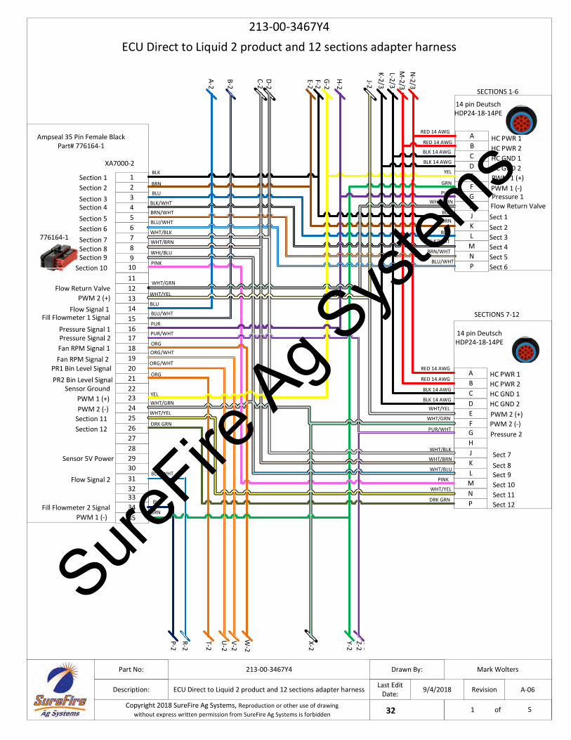
B-2
ECU Direct to Liquid 2 product and 12 sections adapter harness
213-00-3467Y4
9/4/2018
Mark Wolters213-00-3467Y4
ECU Direct to Liquid 2 product and 12 sections adapter harness
Part No:
Description:
Drawn By:
Last Edit Date:
Project:32Copyright 2018 SureFire Ag Systems, Reproduction or other use of drawingwithout express written permission from SureFire Ag Systems is forbidden
Revision
of
A-06
1 5
C-2
123456789
12131415161718192021
28
31
3334
11
32
Section 1
Pressure Signal 1
222324252627
3029
35
Flow Signal 1
PWM 1 (+)
PWM 1 (-)
Sensor 5V Power
BLU
YEL
GRN
BLK/WHT
BLK
PUR
XA7000-2
Section 3Section 2
Section 4Section 5Section 6
BRN
BLU
BRN/WHT
BLU/WHT
X-2
Z-2Y-2
Flow Return Valve
Ampseal 35 Pin Female BlackPart# 776164-1
776164-1
Pressure Signal 2PUR/WHT
Flow Signal 2BLU/WHT
PWM 2 (-)
PWM 2 (+)
WHT/GRN
WHT/YEL
10
Section 7Section 8
Section 10Section 9
Section 12Section 11
WHT/BLK
WHT/BRN
WHt/BLU
PINK
WHT/YEL
DRK GRN
DEFGHJKLMNP
Sect 3Sect 4Sect 5Sect 6
BRN
RED 14 AWG
BLK 14 AWG
BLK
BLU
BLK/WHT
SECTIONS 1-6
BRN/WHT
BLU/WHT
RED 14 AWG
Pressure 1PUR
BLK 14 AWG
ABCDEFGHJKLM
Sect 9Sect 8
Sect 10Sect 11Sect 12
HC PWR 2HC GND 1HC GND 2
WHT/BRN
RED 14 AWG
BLK 14 AWG
WHT/BLK
WHT/BLU
PINK
SECTIONS 7-12
WHT/YEL
DRK GRN
RED 14 AWG
Pressure 2PUR/WHT
BLK 14 AWG
14 pin Deutsch HDP24-18-14PE
Sect 2
C
Sect 1
14 pin Deutsch HDP24-18-14PE
Sect 7
BA
NP
HC PWR 1
HC PWR 1HC PWR 2HC GND 1HC GND 2
PWM 1 (-)PWM 1 (+)
PWM 2 (-)PWM 2 (+)
GRN
YEL
WHT/YEL
WHT/GRN
Flow Return ValveWHT/GRN
Fill Flowmeter 1 Signal
Fan RPM Signal 1Fan RPM Signal 2
PR1 Bin Level SignalPR2 Bin Level Signal
Sensor Ground
Fill Flowmeter 2 Signal
P-2
V-2
W-2
U-2
T-2
R-2
H-2
L-2/3
N-2/3
M-2/3
K-2/3
G-2
C-2D-2
A-2
E-2F-2
J-2
WHT/GRN
ORG/WHT
ORG
ORG
ORG/WHT
BLU
BLU/WHT
SureFire
Ag Sys
tems
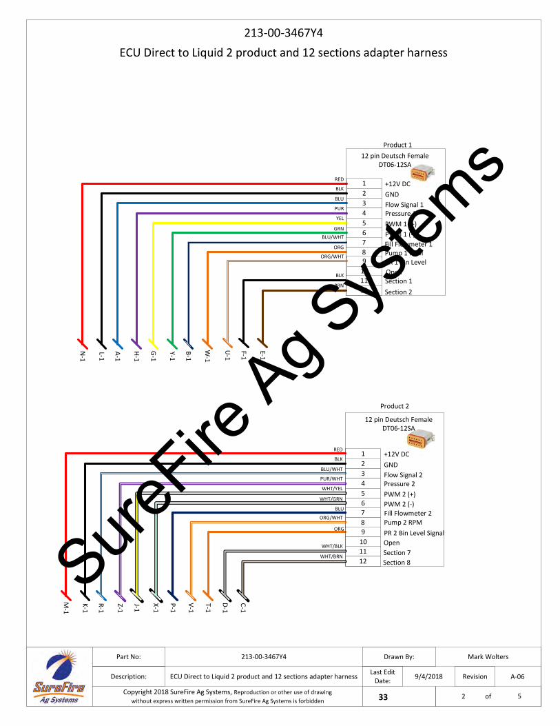
ECU Direct to Liquid 2 product and 12 sections adapter harness
213-00-3467Y4
9/4/2018
Mark Wolters213-00-3467Y4
ECU Direct to Liquid 2 product and 12 sections adapter harness
Part No:
Description:
Drawn By:
Last Edit Date:
Project:33Copyright 2018 SureFire Ag Systems, Reproduction or other use of drawingwithout express written permission from SureFire Ag Systems is forbidden
Revision
of
A-06
2 5
123456
+12V DC
Flow Signal 1GND
Pressure 1PWM 1 (+)PWM 1 (-)
BLU
PUR
YEL
GRN
Product 1
78
BLU/WHT
ORG
RED
BLK
H-1
L-1
N-1
A-1
W-1
Y-1
G-1
B-1
123456
+12V DC
Flow Signal 2GND
Pressure 2PWM 2 (+)PWM 2 (-)
BLU/WHT
PUR/WHT
WHT/YEL
WHT/GRN
Product 2
78
ORG/WHT
RED
BLK
Z-1
K-1
M-1
R-1
V-1
X-1
J-1
Pump 1 RPM
Pump 2 RPM
Fill Flowmeter 1
Fill Flowmeter 2
P-1
BLU
910
PR 1 Bin Level
Section 1
ORG/WHT
1112
BLK
BRNSection 2
Open
910
PR 2 Bin Level SignalORG
1112
WHT/BLK
WHT/BRN
Open
12 pin Deutsch FemaleDT06-12SA
12 pin Deutsch FemaleDT06-12SA
Section 7Section 8
C-1
T-1
D-1
E-1
U-1
F-1
SureFire
Ag Sys
tems
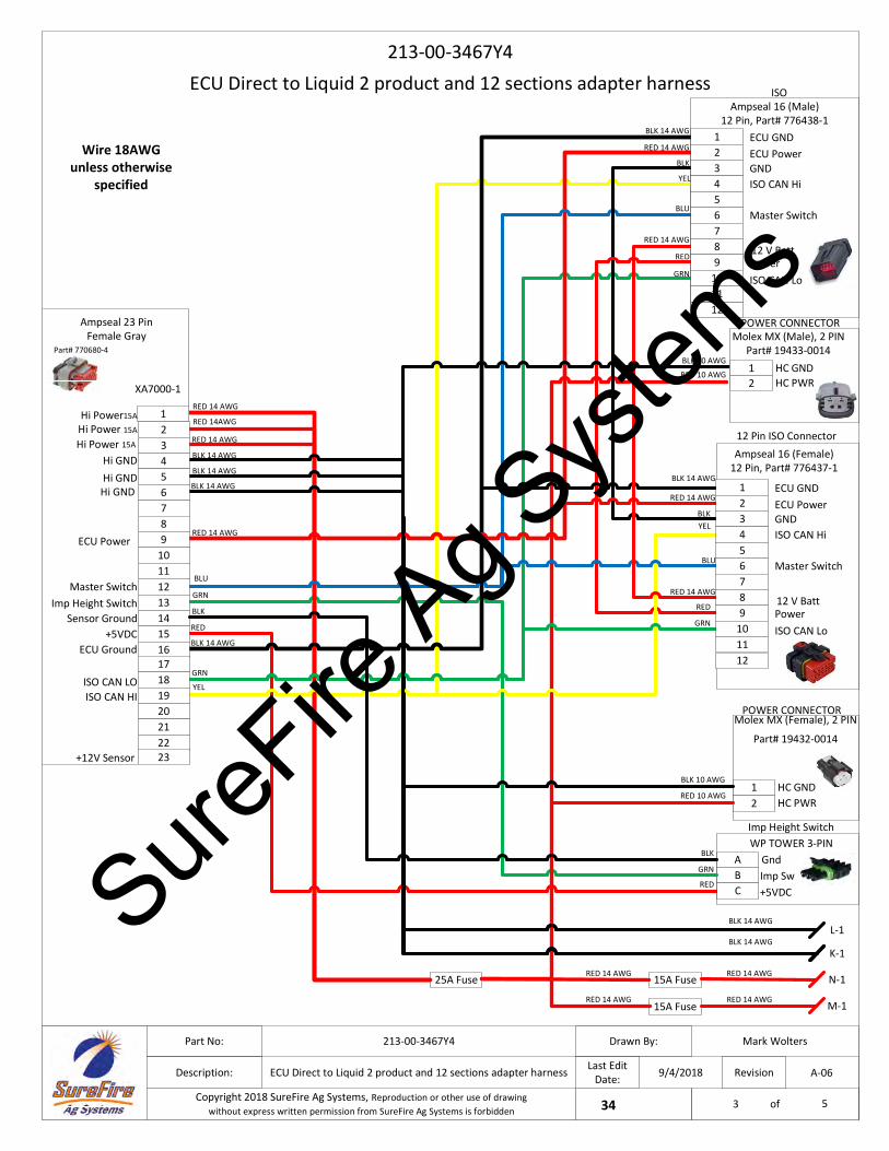
ECU Direct to Liquid 2 product and 12 sections adapter harness
213-00-3467Y4
9/4/2018
Mark Wolters213-00-3467Y4
ECU Direct to Liquid 2 product and 12 sections adapter harness
Part No:
Description:
Drawn By:
Last Edit Date:
Project:34Copyright 2018 SureFire Ag Systems, Reproduction or other use of drawingwithout express written permission from SureFire Ag Systems is forbidden
Revision
of
A-06
3 5
Wire 18AWG unless otherwise
specified
Ground12V Sensor Power
BLK 10 AWG
RED 10 AWG
RED
AWP TOWER 3-PIN
B+5VDC
Imp Height Switch
BLK
Imp Sw
RED 14 AWG
BLK 14 AWG
RED 14 AWG
RED 14 AWG
RED 14 AWG
RED 14AWG
25A Fuse
15A Fuse
15A FuseRED 14 AWG
RED 14 AWG
RED 14 AWG
BLU
GRN
RED
BLK 14 AWG
RED 14 AWG
BLK
12
HC GNDHC PWR
BLK 10 AWG
RED 10 AWG
12 Pin ISO Connector
RED 14 AWG
L-1
K-1
N-1
M-1
BLK 14 AWG
BLK 14 AWG
BLK 14 AWG
BLK 14 AWG
BLK 14 AWG
3
ECU GND
GND
12
YEL456789
10
1211
ECU Power
ISO CAN Hi
Master Switch
12 V BattPowerISO CAN Lo
Ampseal 16 (Female)12 Pin, Part# 776437-1
12
HC GNDHC PWR
Molex MX (Female), 2 PIN
Part# 19432-0014
POWER CONNECTOR
Molex MX (Male), 2 PIN Part# 19433-0014
POWER CONNECTOR
123456789
10
12131415161718192021
11
Hi GNDHi GND
Hi Power15A
Hi Power 15A
ECU Power
Master SwitchImp Height Switch
ECU Ground
ISO CAN HI
2223
Sensor Ground
ISO CAN LO
Hi Power 15A
Hi GND
XA7000-1
BLK
YEL
GRN
BLU
Ampseal 23 Pin Female Gray
Part# 770680-4
3
ECU GND
GND
1
BLU
2
YEL 456789
10
12
GRN
RED
BLK 14 AWG
RED 14 AWG
BLK
11
ECU Power
ISO CAN Hi
Master Switch
12 V BattPowerISO CAN Lo
Ampseal 16 (Male)12 Pin, Part# 776438-1
RED 14 AWG
C
GndGRN
GRN
RED
+12V Sensor
ISO
+5VDC
SureFire
Ag Sys
tems
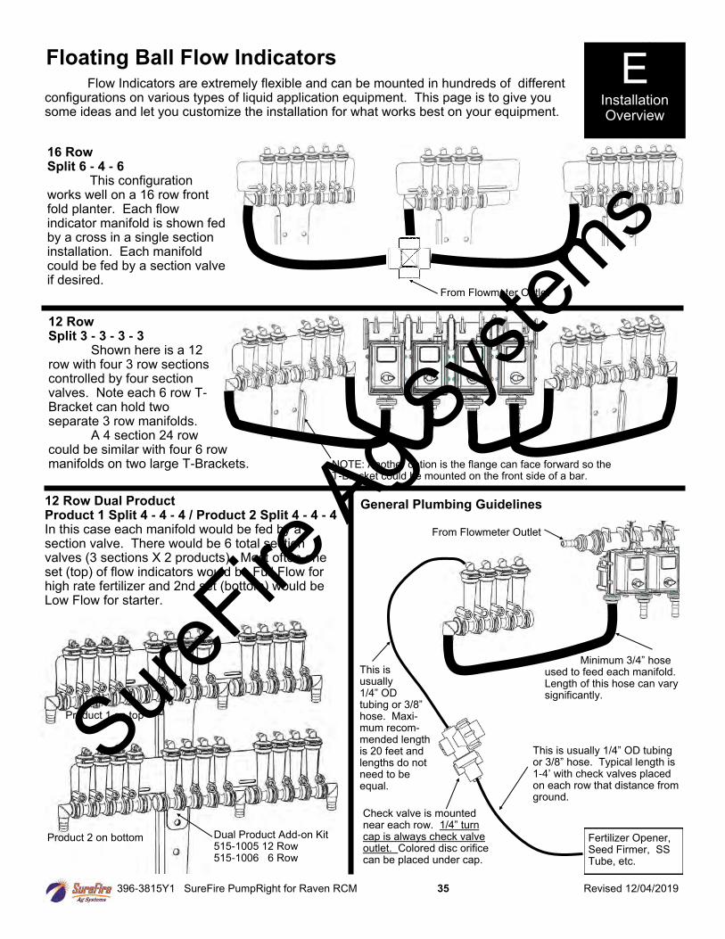
396-3815Y1 SureFire PumpRight for Raven RCM 35 Revised 12/04/2019
Floating Ball Flow Indicators E Installation Overview
Flow Indicators are extremely flexible and can be mounted in hundreds of different configurations on various types of liquid application equipment. This page is to give you some ideas and let you customize the installation for what works best on your equipment.
From Flowmeter Outlet
16 Row Split 6 - 4 - 6 This configuration works well on a 16 row front fold planter. Each flow indicator manifold is shown fed by a cross in a single section installation. Each manifold could be fed by a section valve if desired.
12 Row Split 3 - 3 - 3 - 3 Shown here is a 12 row with four 3 row sections controlled by four section valves. Note each 6 row T-Bracket can hold two separate 3 row manifolds. A 4 section 24 row could be similar with four 6 row manifolds on two large T-Brackets.
12 Row Dual Product Product 1 Split 4 - 4 - 4 / Product 2 Split 4 - 4 - 4 In this case each manifold would be fed by a section valve. There would be 6 total section valves (3 sections X 2 products). Most often one set (top) of flow indicators would be Full Flow for high rate fertilizer and 2nd set (bottom) would be Low Flow for starter.
Dual Product Add-on Kit 515-1005 12 Row 515-1006 6 Row
NOTE: Another option is the flange can face forward so the T-Bracket could be mounted on the front side of a bar.
General Plumbing Guidelines
Fertilizer Opener, Seed Firmer, SS Tube, etc.
From Flowmeter Outlet
Minimum 3/4” hose used to feed each manifold. Length of this hose can vary significantly.
This is usually 1/4” OD tubing or 3/8” hose. Typical length is 1-4’ with check valves placed on each row that distance from ground.
This is usually 1/4” OD tubing or 3/8” hose. Maxi-mum recom-mended length is 20 feet and lengths do not need to be equal.
Check valve is mounted near each row. 1/4” turn cap is always check valve outlet. Colored disc orifice can be placed under cap.
Product 1 on top
Product 2 on bottom
SureFire
Ag Sys
tems
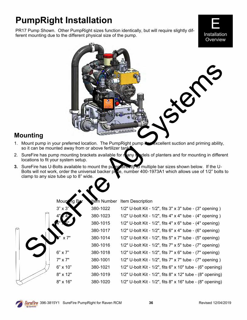
396-3815Y1 SureFire PumpRight for Raven RCM 36 Revised 12/04/2019
PumpRight Installation PR17 Pump Shown. Other PumpRight sizes function identically, but will require slightly dif-ferent mounting due to the different physical size of the pump.
Mounting 1. Mount pump in your preferred location. The PumpRight pump has excellent suction and priming ability,
so it can be mounted away from or above fertilizer tanks.
2. SureFire has pump mounting brackets available for many models of planters and for mounting in differentlocations to fit your system setup.
3. SureFire has U-Bolts available to mount the pump directly to multiple bar sizes shown below. If the U-Bolts will not work, order the universal backer plate, number 400-1973A1 which allows use of 1/2” bolts toclamp to any size tube up to 8” wide.
E Installation Overview
Mounting Bar Item Number Item Description
3” x 3” 380-1022 1/2" U-bolt Kit - 1/2", fits 3" x 3" tube - (3" opening )
4" x 4" 380-1023 1/2" U-bolt Kit - 1/2", fits 4" x 4" tube - (4" opening )
4" x 6" 380-1015 1/2" U-bolt Kit - 1/2", fits 4" x 6" tube - (4" opening)
380-1017 1/2" U-bolt Kit - 1/2", fits 6" x 4" tube - (6" opening)
5" x 7" 380-1014 1/2" U-bolt Kit - 1/2", fits 5" x 7" tube - (5" opening)
380-1016 1/2" U-bolt Kit - 1/2", fits 7" x 5" tube - (7" opening)
6” x 7” 380-1018 1/2" U-bolt Kit - 1/2", fits 7" x 6" tube - (7" opening)
7" x 7" 380-1001 1/2" U-bolt Kit - 1/2", fits 7" x 7" tube - (7" opening )
6” x 10” 380-1021 1/2" U-bolt Kit - 1/2", fits 6" x 10" tube - (6" opening)
8" x 12" 380-1019 1/2" U-bolt Kit - 1/2", fits 8" x 12" tube - (8" opening)
8" x 16" 380-1020 1/2" U-bolt Kit - 1/2", fits 8" x 16" tube - (8" opening)
SureFire
Ag Sys
tems
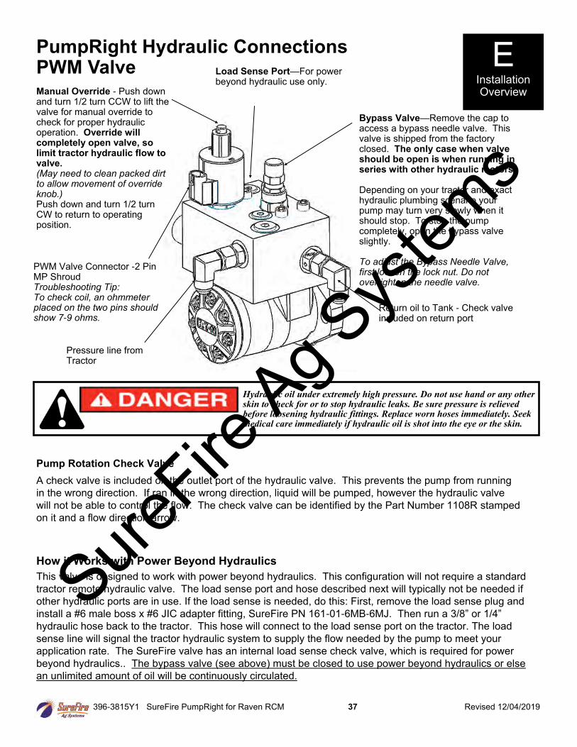
396-3815Y1 SureFire PumpRight for Raven RCM 37 Revised 12/04/2019
PumpRight Hydraulic Connections PWM Valve Load Sense Port—For power
beyond hydraulic use only.
Return oil to Tank - Check valve included on return port
Bypass Valve—Remove the cap to access a bypass needle valve. This valve is shipped from the factory closed. The only case when valve should be open is when running in series with other hydraulic motors. Depending on your tractor and exact hydraulic plumbing scenario your pump may turn very slowly when it should stop. To stop the pump completely, open the bypass valve slightly. To adjust the Bypass Needle Valve, first loosen the lock nut. Do not overtighten the needle valve.
Pump Rotation Check Valve
A check valve is included on the outlet port of the hydraulic valve. This prevents the pump from running
in the wrong direction. If ran in the wrong direction, liquid will be pumped, however the hydraulic valve
will not be able to control the flow. The check valve can be identified by the Part Number 1108R stamped
on it and a flow direction arrow.
Pressure line from Tractor
PWM Valve Connector -2 Pin MP Shroud Troubleshooting Tip: To check coil, an ohmmeter placed on the two pins should show 7-9 ohms.
Manual Override - Push down and turn 1/2 turn CCW to lift the valve for manual override to check for proper hydraulic operation. Override will completely open valve, so limit tractor hydraulic flow to valve. (May need to clean packed dirt to allow movement of override knob.) Push down and turn 1/2 turn CW to return to operating position.
E Installation Overview
Hydraulic oil under extremely high pressure. Do not use hand or any other skin to check for or to stop hydraulic leaks. Be sure pressure is relieved before loosening hydraulic fittings. Replace worn hoses immediately. Seek medical care immediately if hydraulic oil is shot into the eye or the skin.
How it Works with Power Beyond Hydraulics
This valve is designed to work with power beyond hydraulics. This configuration will not require a standard
tractor remote hydraulic valve. The load sense port and hose described next will typically not be needed if
other hydraulic ports are in use. If the load sense is needed, do this: First, remove the load sense plug and
install a #6 male boss x #6 JIC adapter fitting, SureFire PN 161-01-6MB-6MJ. Then run a 3/8” or 1/4”
hydraulic hose back to the tractor. This hose will connect to the load sense port on the tractor. The load
sense line will signal the tractor hydraulic system to supply the flow needed by the pump to meet your
application rate. The SureFire valve has an internal load sense check valve, which is required for power
beyond hydraulics.. The bypass valve (see above) must be closed to use power beyond hydraulics or else
an unlimited amount of oil will be continuously circulated.
SureFire
Ag Sys
tems

396-3815Y1 SureFire PumpRight for Raven RCM 38 Revised 12/04/2019
PumpRight Hydraulic Connections
Hydraulic Hose SureFire recommends 1/2” hydraulic hose for both pump inlet and outlet. The hoses
will need #8 JIC female swivel fittings.
Where do I get hydraulic flow for my PumpRight? This question is often asked as many implements use up all the hydraulic connections on a tractor. SureFire
has some recommendations as to what works best.
Best Option - Dedicated PumpRight Circuit
If you have a tractor remote available, attach the tractor remote valve
directly to the PumpRight pressure and return ports. DO NOT try to avoid this method
simply to save another set of hydraulic hoses running to the tractor. Operating the PumpRight on it’s
own circuit is the simplest for installation and operation. It guarantees the PumpRight won’t negatively affect
any other hydraulic components on your equipment.
Alternate Option - In Series with John Deere CCS Fan or Bulk Fill Seed Fan
If you do not have a tractor remote valve available, this may be your best method. You can plumb the
PumpRight after the seed distribution fan in series. If using this method, the SureFire PWM bypass valve
must be open (see previous page for instruction & picture). If bypass is left closed, the SureFire valve will
limit the speed of the seed distribution fan.
For example, the John Deere CCS fan uses around 7 GPM of oil. This will limit the PumpRight maximum
flow (9 GPM oil necessary for maximum flow). See the charts on the next page for adjusted maximum pump
flow. See section G for flow charts to determine your necessary flow rate.
DO NOT plumb the PumpRight in series with a vacuum fan. The vacuum fan uses just a few GPM of oil.
Also, problems will be caused by excessive pressure at the vacuum fan motor
Two PumpRights
The preferred method is to plumb the two pumps in series. DO NOT plumb two pumps after the CCS fan.
Excessive pressures may damage the CCS fan motor. Run the pressure line from tractor to first pump inlet.
Plumb from the outlet of Pump 1 to the Inlet of Pump 2, then from Pump 2 outlet back to the tractor. Open
the bypass needle valve on both pumps so each valve controls motor speed independently. Run the flow
setting procedure on the next page to minimize the hydraulic flow based on the pump that requires more
hydraulic motor flow.
E Installation Overview
Hydraulic oil under extremely high pressure. Do not use hand or any other skin to check for or to stop hydraulic leaks. Be sure pressure is relieved before loosening hydraulic fittings. Replace worn hoses immediately. Seek medical care immediately if hydraulic oil is shot into the eye or the skin.
SureFire
Ag Sys
tems
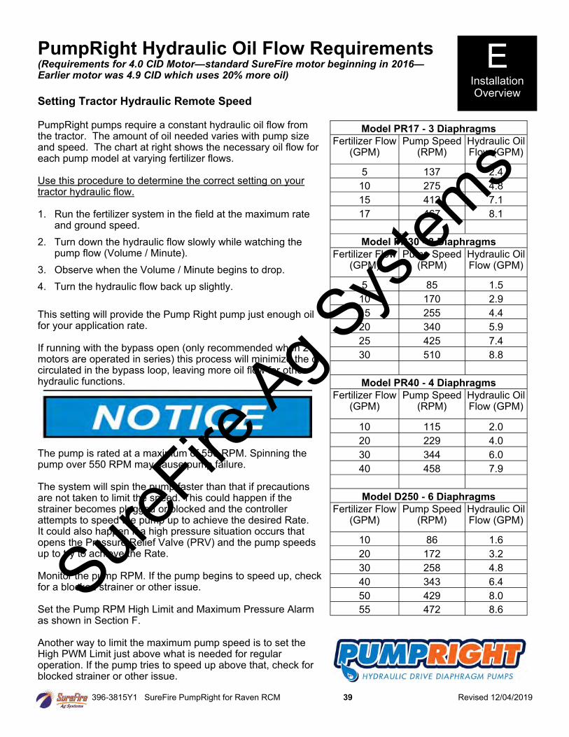
396-3815Y1 SureFire PumpRight for Raven RCM 39 Revised 12/04/2019
PumpRight Hydraulic Oil Flow Requirements (Requirements for 4.0 CID Motor—standard SureFire motor beginning in 2016— Earlier motor was 4.9 CID which uses 20% more oil)
Setting Tractor Hydraulic Remote Speed PumpRight pumps require a constant hydraulic oil flow from the tractor. The amount of oil needed varies with pump size and speed. The chart at right shows the necessary oil flow for each pump model at varying fertilizer flows. Use this procedure to determine the correct setting on your tractor hydraulic flow. 1. Run the fertilizer system in the field at the maximum rate
and ground speed.
2. Turn down the hydraulic flow slowly while watching the pump flow (Volume / Minute).
3. Observe when the Volume / Minute begins to drop.
4. Turn the hydraulic flow back up slightly.
This setting will provide the Pump Right pump just enough oil for your application rate. If running with the bypass open (only recommended when 2 motors are operated in series) this process will minimize the oil circulated in the bypass loop, leaving more oil flow for other hydraulic functions.
The pump is rated at a maximum of 550 RPM. Spinning the pump over 550 RPM may cause pump failure. The system will spin the pump faster than that if precautions are not taken to limit the speed. This could happen if the strainer becomes plugged or blocked and the controller attempts to speed the pump up to achieve the desired Rate. It could also happen if a high pressure situation occurs that opens the Pressure Relief Valve (PRV) and the pump speeds up to try to achieve the Rate. Monitor the pump RPM. If the pump begins to speed up, check for a blocked strainer or other issue. Set the Pump RPM High Limit and Maximum Pressure Alarm as shown in Section F. Another way to limit the maximum pump speed is to set the High PWM Limit just above what is needed for regular operation. If the pump tries to speed up above that, check for blocked strainer or other issue.
E Installation Overview
Model PR17 - 3 Diaphragms
Fertilizer Flow (GPM)
Pump Speed (RPM)
Hydraulic Oil Flow (GPM)
5 137 2.4
10 275 4.8
15 412 7.1
17 467 8.1
Model PR30 - 3 Diaphragms
Fertilizer Flow (GPM)
Pump Speed (RPM)
Hydraulic Oil Flow (GPM)
5 85 1.5
10 170 2.9
15 255 4.4
20 340 5.9
25 425 7.4
30 510 8.8
Model PR40 - 4 Diaphragms
Fertilizer Flow (GPM)
Pump Speed (RPM)
Hydraulic Oil Flow (GPM)
10 115 2.0
20 229 4.0
30 344 6.0
40 458 7.9
Model D250 - 6 Diaphragms
Fertilizer Flow (GPM)
Pump Speed (RPM)
Hydraulic Oil Flow (GPM)
10 86 1.6
20 172 3.2
30 258 4.8
40 343 6.4
50 429 8.0
55 472 8.6
SureFire
Ag Sys
tems
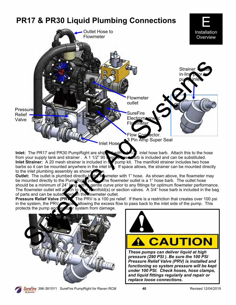
396-3815Y1 SureFire PumpRight for Raven RCM 40 Revised 12/04/2019
PR17 & PR30 Liquid Plumbing Connections
Outlet Hose to Flowmeter
Pressure Relief Valve
Flowmeter outlet
Inlet: The PR17 and PR30 PumpRight are shipped with a 1 1/2” inlet hose barb. Attach this to the hose from your supply tank and strainer . A 1 1/2” 90 degree hose barb is included and can be substituted. Inlet Strainer: A 20 mesh strainer is included in the pump kit. The manifold strainer includes two hose barbs so it can be mounted anywhere in the inlet line. If space allows, the strainer can be mounted directly to the inlet plumbing assembly as shown below. Outlet: The outlet is plumbed directly to the flowmeter with 1” hose. As shown above, the flowmeter may be mounted directly to the PumpRight pump. The flowmeter outlet is a 1” hose barb. The outlet hose should be a minimum of 24” long with a gentle curve prior to any fittings for optimum flowmeter performance. The flowmeter outlet will attach to your manifold(s) or section valves. A 3/4” hose barb is included in the bag of parts and can be substituted on the flowmeter outlet. Pressure Relief Valve (PRV): The PRV is a 100 psi relief. If there is a restriction that creates over 100 psi in the system, the PRV will open allowing the excess flow to pass back to the inlet side of the pump. This protects the pump and fertilizer system from damage.
Strainer - Install in-line prior to pump inlet
E Installation Overview
SureFire Electromagnetic Flowmeter
Inlet Hose
Flow Connector. 3 Pin Amp Super Seal
These pumps can deliver liquid at high pressure (290 PSI ). Be sure the 100 PSI Pressure Relief Valve (PRV) is installed and functioning so system pressure will be kept under 100 PSI. Check hoses, hose clamps, and liquid fittings regularly and repair or replace loose connections.
SureFire
Ag Sys
tems
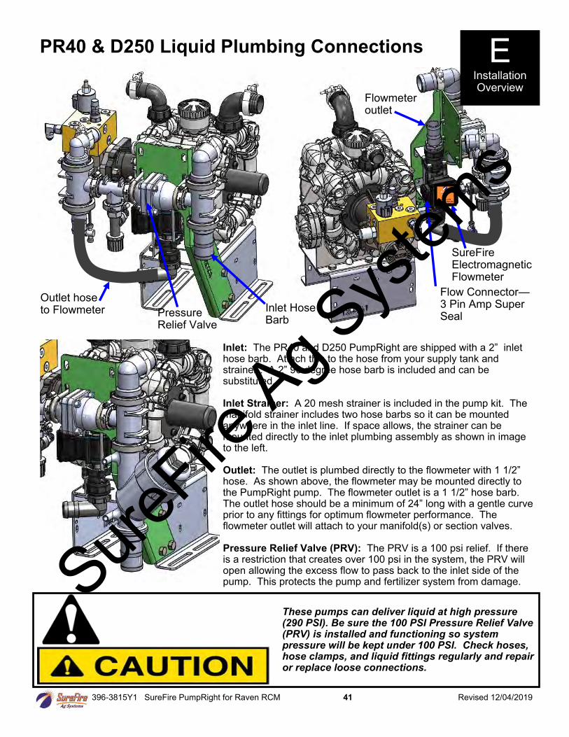
396-3815Y1 SureFire PumpRight for Raven RCM 41 Revised 12/04/2019
PR40 & D250 Liquid Plumbing Connections
Inlet Hose Barb
Pressure Relief Valve
SureFire Electromagnetic Flowmeter
Flow Connector—3 Pin Amp Super Seal
Flowmeter outlet
Inlet: The PR40 and D250 PumpRight are shipped with a 2” inlet hose barb. Attach this to the hose from your supply tank and strainer . A 2” 90 degree hose barb is included and can be substituted. Inlet Strainer: A 20 mesh strainer is included in the pump kit. The manifold strainer includes two hose barbs so it can be mounted anywhere in the inlet line. If space allows, the strainer can be mounted directly to the inlet plumbing assembly as shown in image to the left. Outlet: The outlet is plumbed directly to the flowmeter with 1 1/2” hose. As shown above, the flowmeter may be mounted directly to the PumpRight pump. The flowmeter outlet is a 1 1/2” hose barb. The outlet hose should be a minimum of 24” long with a gentle curve prior to any fittings for optimum flowmeter performance. The flowmeter outlet will attach to your manifold(s) or section valves. Pressure Relief Valve (PRV): The PRV is a 100 psi relief. If there is a restriction that creates over 100 psi in the system, the PRV will open allowing the excess flow to pass back to the inlet side of the pump. This protects the pump and fertilizer system from damage.
E Installation Overview
Outlet hose to Flowmeter
These pumps can deliver liquid at high pressure (290 PSI). Be sure the 100 PSI Pressure Relief Valve (PRV) is installed and functioning so system pressure will be kept under 100 PSI. Check hoses, hose clamps, and liquid fittings regularly and repair or replace loose connections.
SureFire
Ag Sys
tems
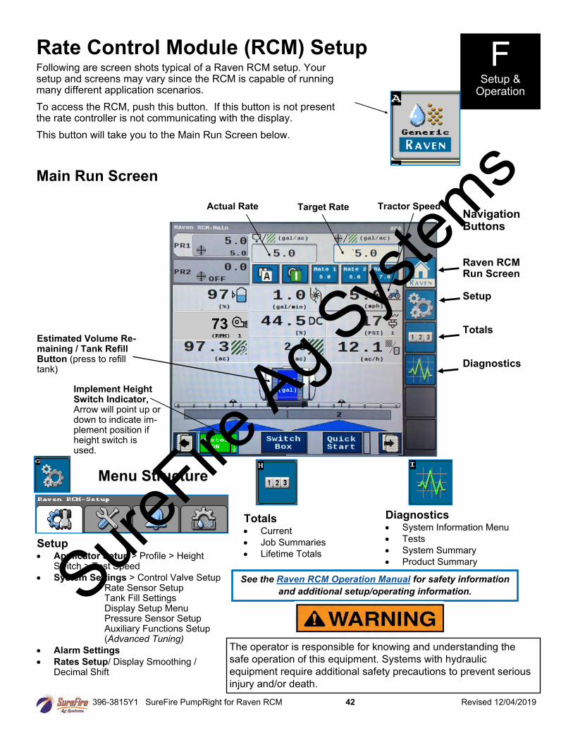
396-3815Y1 SureFire PumpRight for Raven RCM 42 Revised 12/04/2019
Following are screen shots typical of a Raven RCM setup. Your setup and screens may vary since the RCM is capable of running many different application scenarios.
To access the RCM, push this button. If this button is not present the rate controller is not communicating with the display.
This button will take you to the Main Run Screen below.
Rate Control Module (RCM) Setup
Menu Structure
Navigation Buttons Raven RCM Run Screen Setup Totals Diagnostics
Main Run Screen
Actual Rate Target Rate Tractor Speed
Totals • Current
• Job Summaries
• Lifetime Totals
Diagnostics • System Information Menu
• Tests
• System Summary
• Product Summary
F Setup &
Operation
Estimated Volume Re-maining / Tank Refill Button (press to refill tank)
Implement Height Switch Indicator, Arrow will point up or down to indicate im-plement position if height switch is used.
Setup • Applicator Setup > Profile > Height
Switch > Test Speed
• System Settings > Control Valve Setup Rate Sensor Setup Tank Fill Settings Display Setup Menu Pressure Sensor Setup Auxiliary Functions Setup (Advanced Tuning)
• Alarm Settings
• Rates Setup/ Display Smoothing / Decimal Shift
73
See the Raven RCM Operation Manual for safety information
and additional setup/operating information.
The operator is responsible for knowing and understanding the
safe operation of this equipment. Systems with hydraulic
equipment require additional safety precautions to prevent serious
injury and/or death.
SureFire
Ag Sys
tems
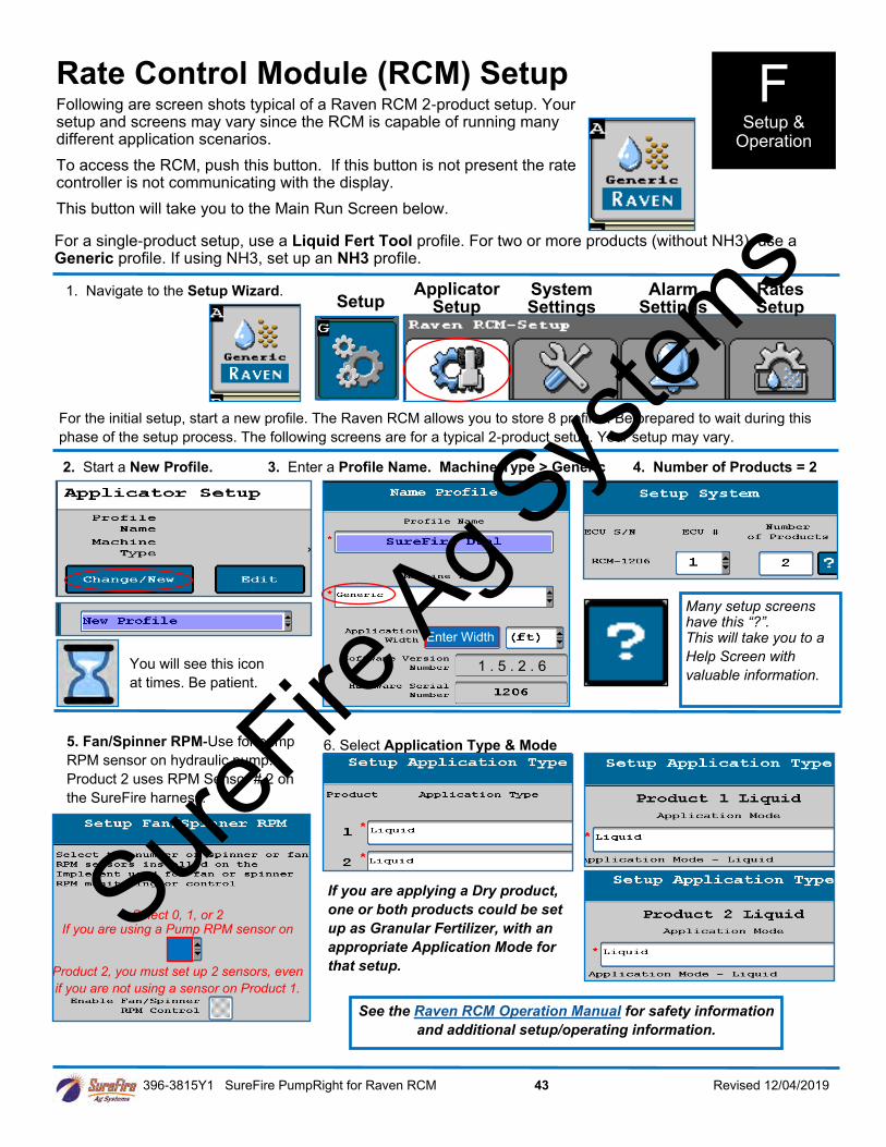
396-3815Y1 SureFire PumpRight for Raven RCM 43 Revised 12/04/2019
1. Navigate to the Setup Wizard.
2. Start a New Profile. 3. Enter a Profile Name. Machine Type > Generic 4. Number of Products = 2
For the initial setup, start a new profile. The Raven RCM allows you to store 8 profiles. Be prepared to wait during this
phase of the setup process. The following screens are for a typical 2-product setup. Your setup may vary.
6. Select Application Type & Mode 5. Fan/Spinner RPM-Use for pump
RPM sensor on hydraulic pump.
Product 2 uses RPM Sensor # 2 on
the SureFire harness.
You will see this icon
at times. Be patient.
Many setup screens have this “?”. This will take you to a
Help Screen with
valuable information.
See the Raven RCM Operation Manual for safety information
and additional setup/operating information.
Setup Applicator
Setup System Settings
Alarm Settings
Rates Setup
Enter Width
Select 0, 1, or 2 If you are using a Pump RPM sensor on
Product 2, you must set up 2 sensors, even
if you are not using a sensor on Product 1.
If you are applying a Dry product,
one or both products could be set
up as Granular Fertilizer, with an
appropriate Application Mode for
that setup.
Following are screen shots typical of a Raven RCM 2-product setup. Your setup and screens may vary since the RCM is capable of running many different application scenarios.
To access the RCM, push this button. If this button is not present the rate controller is not communicating with the display.
This button will take you to the Main Run Screen below.
Rate Control Module (RCM) Setup F Setup &
Operation
For a single-product setup, use a Liquid Fert Tool profile. For two or more products (without NH3), use a Generic profile. If using NH3, set up an NH3 profile.
1 . 5 . 2 . 6
SureFire
Ag Sys
tems
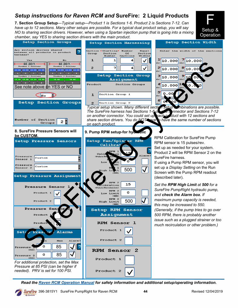
396-3815Y1 SureFire PumpRight for Raven RCM 44 Revised 12/04/2019
Setup instructions for Raven RCM and SureFire: 2 Liquid Products
8. SureFire Pressure Sensors will
be CUSTOM. 9. Pump RPM setup-for hydraulic
RPM Calibration for SureFire Pump
RPM sensor is 15 pulses/rev.
Set up as needed for your system.
Product 2 will be RPM Sensor 2 on the
SureFire harness.
If using a Pump RPM sensor, you will
set up a Display Setting on the Run
Screen with the Pump RPM readout
(described later).
Set the RPM High Limit at 500 for a
SureFIre PumpRight hydraulic pump,
and check the Alarm box. If
maximum pump capacity is needed,
this may be increased to 550.
(Generally, if the pump tries to go over
500 RPM, there is probably another
issue such as a plugged strainer or too
much recirculation or other problem.)
Read the Raven RCM Operation Manual for safety information and additional setup/operating information.
Typical setup shown. Many different section setup combinations are possible. The SureFire harness has Sections 1-6 on one connector and Sections 7-12 on another connector. You could set up each product with 12 sections and share section drivers. You do NOT have to have the same number of sections on each product.
For additional protection, set the Max Pressure at 85 PSI (can be higher if needed). PRV is set for 100 PSI.
7. Section Group Setup—Typical setup—Product 1 is Sections 1-6. Product 2 is Sections 7-12. Can
have up to 12 sections. Many other setups are possible. For a typical dual product setup, you will say
NO to sharing section drivers. However, when using a Spartan injection pump that is going into a mixing
chamber, say YES to sharing section drivers with the main product.
F Setup &
Operation
See note above on YES or NO
85
85
500
500
SureFire
Ag Sys
tems

396-3815Y1 SureFire PumpRight for Raven RCM 45 Revised 12/04/2019
Setup instructions for Raven RCM and SureFire: 2 Liquid Products
Valve Response Rate: (Adjust as needed)
PumpRight (hydraulic) 1
Tower (electric) 20
Catalyst and Spartan 5
Control Deadband: Start at 2
Flowmeter Size (GPM)
Pulses/Gal
0.08-1.6 22710
0.13-2.6 3000
0.3-5.0 3000
0.6-13 2000
1.3-26 2000
2.6-53 2000
10. Control Valve Setup (start with the numbers indicated for your system)
11. Enter appropriate Flowmeter Cal. 12(a). Tank and Fill Flowmeter setup 12(b). Fill Flowmeter Cal setup
13. Set Rates as desired.
You must enter at least one rate.
Check Display Smoothing
Set the Decimal Shift box at 1.
Set Decimal Shift at 2 for rates such as 0.25 gal/ac.
14. Set Off-Rate Alarm as desired.
Spartan model
#
Puls/fl oz
110 1760
120 880
130 440
140 220
F Setup &
Operation
See at
Left
Low Limit (Adjust in field as needed)
PumpRight (hydraulic) 25
Tower (electric) 8
Catalyst and Spartan 5
PWM Startup (Adjust in field as needed)
PumpRight (hydraulic) 40
Tower (electric) 30
Catalyst and Spartan 10
See below
See Above
If pump is slow responding to rate
or speed changes, increase Valve
Response Rate. If product oscil-
lates around rate going across the
field, reduce Valve Response
Rate.
Could set PWM High Limit less
than 100 to limit pump speed.
SureFire Electromagnetic Flowmeters. Verify pls/gal on Serial Number label.
OPTIONAL: Use as desired Then enter Tank Fill Flowmeter Calibration
SFA 3” Fill Flowmeter 130
SFA 2” Fill Flowmeter 300
(Units are 10 gal on SureFire Tank Fill flowmeters .)
Check Tank Fill Monitor box if using a fill flowmeter.
Read the Raven RCM Operation Manual for safety information and additional setup/operating information.
Fine-tune PWM Low Limit at Diagnostics > Tests > Calibrate PWM Limits
Set up Product 2 in a similar fashion to the Product 1 setup.
OPTIONAL
For high rates, decimal shift can be set at 0, if desired.
SureFire
Ag Sys
tems
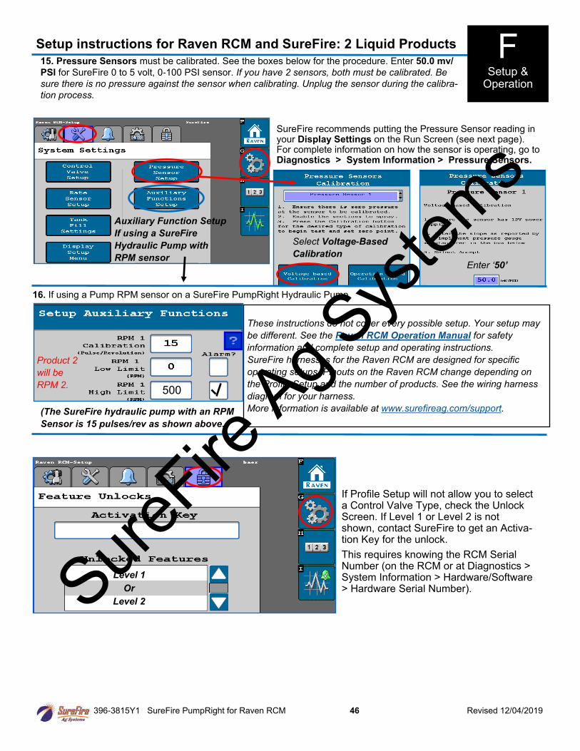
396-3815Y1 SureFire PumpRight for Raven RCM 46 Revised 12/04/2019
(The SureFire hydraulic pump with an RPM
Sensor is 15 pulses/rev as shown above.
These instructions do not cover every possible setup. Your setup may
be different. See the Raven RCM Operation Manual for safety
information and complete setup and operating instructions.
SureFire harnesses for the Raven RCM are designed for specific
operating setups. Pinouts on the Raven RCM change depending on
the Profile Setup and the number of products. See the wiring harness
diagram for your harness.
More information is available at www.surefireag.com/support.
16. If using a Pump RPM sensor on a SureFire PumpRight Hydraulic Pump
Select Voltage-Based
Calibration
Enter ‘50’
Auxiliary Function Setup
If using a SureFire
Hydraulic Pump with
RPM sensor
Product 2
will be
RPM 2.
Setup instructions for Raven RCM and SureFire: 2 Liquid Products
15. Pressure Sensors must be calibrated. See the boxes below for the procedure. Enter 50.0 mv/
PSI for SureFire 0 to 5 volt, 0-100 PSI sensor. If you have 2 sensors, both must be calibrated. Be
sure there is no pressure against the sensor when calibrating. Unplug the sensor during the calibra-
tion process.
SureFire recommends putting the Pressure Sensor reading in your Display Settings on the Run Screen (see next page). For complete information on how the sensor is operating, go to Diagnostics > System Information > Pressure Sensors.
F Setup &
Operation
500
Level 1
Or
Level 2
If Profile Setup will not allow you to select a Control Valve Type, check the Unlock Screen. If Level 1 or Level 2 is not shown, contact SureFire to get an Activa-tion Key for the unlock.
This requires knowing the RCM Serial Number (on the RCM or at Diagnostics > System Information > Hardware/Software > Hardware Serial Number). Sure
Fire Ag S
ystem
s
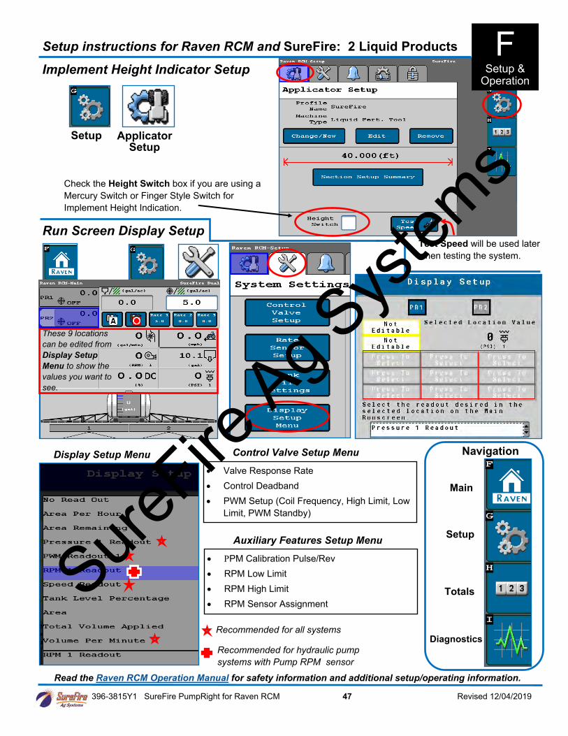
396-3815Y1 SureFire PumpRight for Raven RCM 47 Revised 12/04/2019
Display Setup Menu
Recommended for all systems
Recommended for hydraulic pump
systems with Pump RPM sensor
Run Screen Display Setup
Read the Raven RCM Operation Manual for safety information and additional setup/operating information.
Setup
Totals
Main
Diagnostics
Navigation
Implement Height Indicator Setup
Setup Applicator Setup
Check the Height Switch box if you are using a
Mercury Switch or Finger Style Switch for
Implement Height Indication.
Test Speed will be used later
when testing the system.
Setup instructions for Raven RCM and SureFire: 2 Liquid Products
• Valve Response Rate
• Control Deadband
• PWM Setup (Coil Frequency, High Limit, Low
Limit, PWM Standby)
Control Valve Setup Menu
• PM Calibration Pulse/Rev
• RPM Low Limit
• RPM High Limit
• RPM Sensor Assignment
Auxiliary Features Setup Menu
These 9 locations
can be edited from
Display Setup
Menu to show the
values you want to
see.
F Setup &
Operation
SureFire
Ag Sys
tems
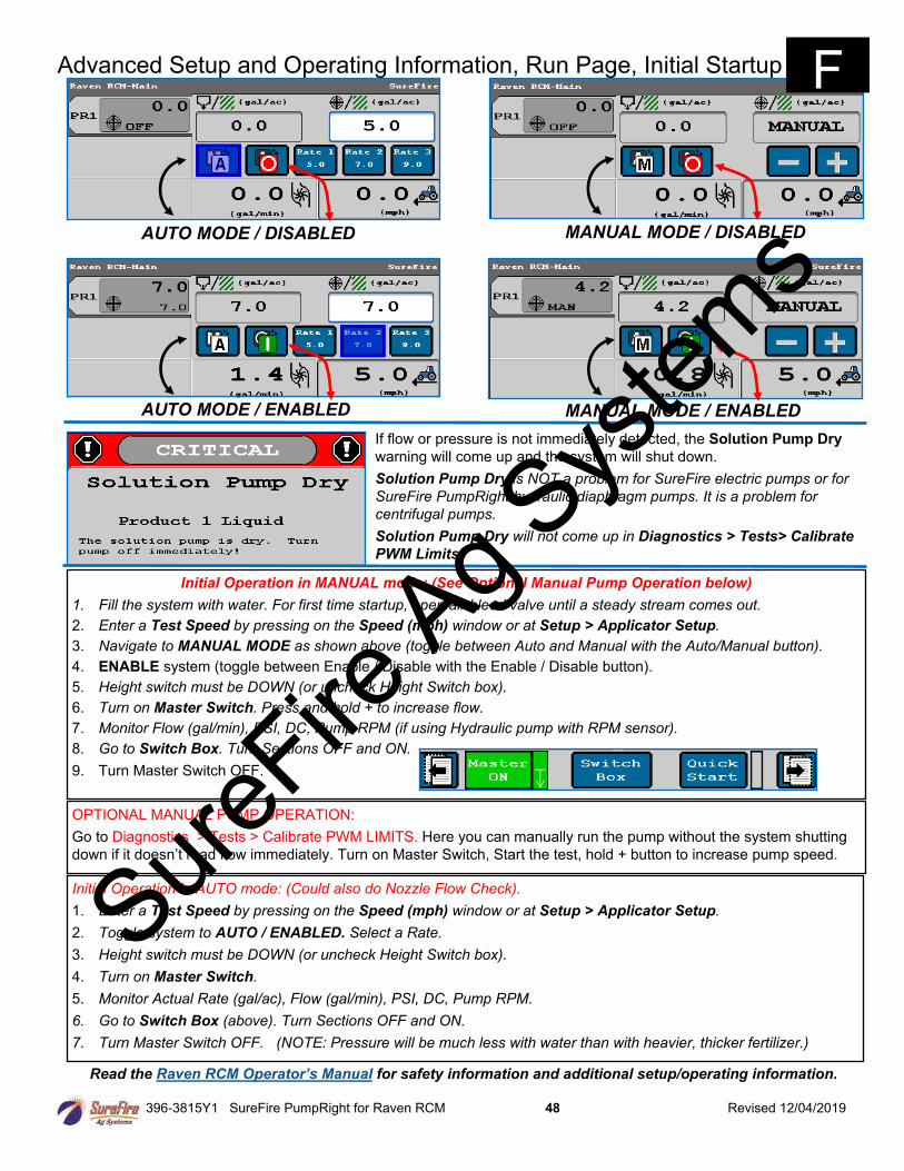
396-3815Y1 SureFire PumpRight for Raven RCM 48 Revised 12/04/2019
Initial Operation in AUTO mode: (Could also do Nozzle Flow Check).
1. Enter a Test Speed by pressing on the Speed (mph) window or at Setup > Applicator Setup.
2. Toggle system to AUTO / ENABLED. Select a Rate.
3. Height switch must be DOWN (or uncheck Height Switch box).
4. Turn on Master Switch.
5. Monitor Actual Rate (gal/ac), Flow (gal/min), PSI, DC, Pump RPM.
6. Go to Switch Box (above). Turn Sections OFF and ON.
7. Turn Master Switch OFF. (NOTE: Pressure will be much less with water than with heavier, thicker fertilizer.)
Initial Operation in MANUAL mode: (See Optional Manual Pump Operation below)
1. Fill the system with water. For first time startup, open air bleed valve until a steady stream comes out.
2. Enter a Test Speed by pressing on the Speed (mph) window or at Setup > Applicator Setup.
3. Navigate to MANUAL MODE as shown above (toggle between Auto and Manual with the Auto/Manual button).
4. ENABLE system (toggle between Enable / Disable with the Enable / Disable button).
5. Height switch must be DOWN (or uncheck Height Switch box).
6. Turn on Master Switch. Press and hold + to increase flow.
7. Monitor Flow (gal/min), PSI, DC, Pump RPM (if using Hydraulic pump with RPM sensor).
8. Go to Switch Box. Turn Sections OFF and ON.
9. Turn Master Switch OFF.
OPTIONAL MANUAL PUMP OPERATION:
Go to Diagnostics > Tests > Calibrate PWM LIMITS. Here you can manually run the pump without the system shutting
down if it doesn’t read flow immediately. Turn on Master Switch, Start the test, hold + button to increase pump speed.
Advanced Setup and Operating Information, Run Page, Initial Startup
AUTO MODE / DISABLED MANUAL MODE / DISABLED
AUTO MODE / ENABLED MANUAL MODE / ENABLED
If flow or pressure is not immediately detected, the Solution Pump Dry
warning will come up and the system will shut down.
Solution Pump Dry is NOT a problem for SureFire electric pumps or for
SureFire PumpRight hydraulic diaphragm pumps. It is a problem for
centrifugal pumps.
Solution Pump Dry will not come up in Diagnostics > Tests> Calibrate
PWM Limits.
Read the Raven RCM Operator’s Manual for safety information and additional setup/operating information.
F
SureFire
Ag Sys
tems
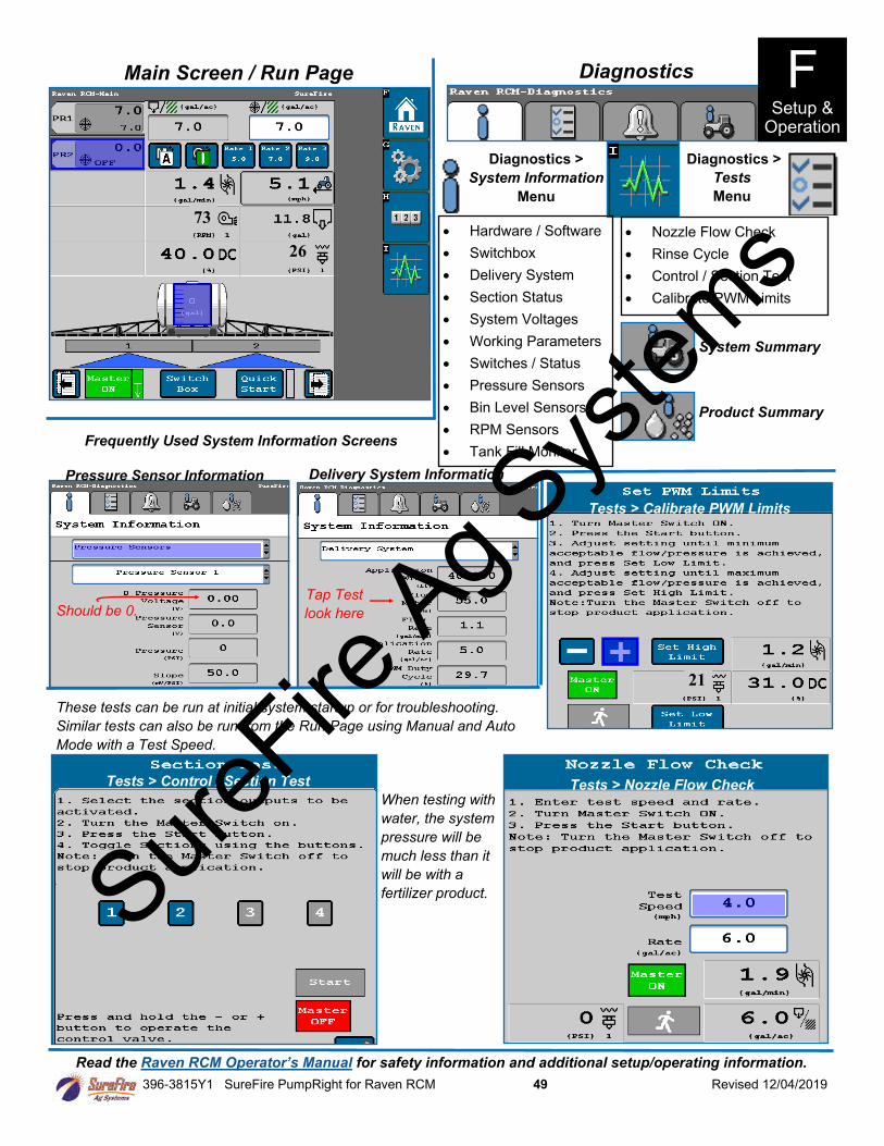
396-3815Y1 SureFire PumpRight for Raven RCM 49 Revised 12/04/2019
Read the Raven RCM Operator’s Manual for safety information and additional setup/operating information.
Main Screen / Run Page
26
73
Diagnostics >
System Information
Menu
• Hardware / Software
• Switchbox
• Delivery System
• Section Status
• System Voltages
• Working Parameters
• Switches / Status
• Pressure Sensors
• Bin Level Sensors
• RPM Sensors
• Tank Fill Monitor
Diagnostics >
Tests
Menu
• Nozzle Flow Check
• Rinse Cycle
• Control / Section Test
• Calibrate PWM Limits
Diagnostics
System Summary
Product Summary
Pressure Sensor Information Delivery System Information
Should be 0.
Frequently Used System Information Screens
Tests > Control / Section Test Tests > Nozzle Flow Check
These tests can be run at initial system startup or for troubleshooting.
Similar tests can also be run from the Run Page using Manual and Auto
Mode with a Test Speed.
When testing with
water, the system
pressure will be
much less than it
will be with a
fertilizer product.
Tests > Calibrate PWM Limits
21
Tap Test
look here
F Setup &
Operation
SureFire
Ag Sys
tems
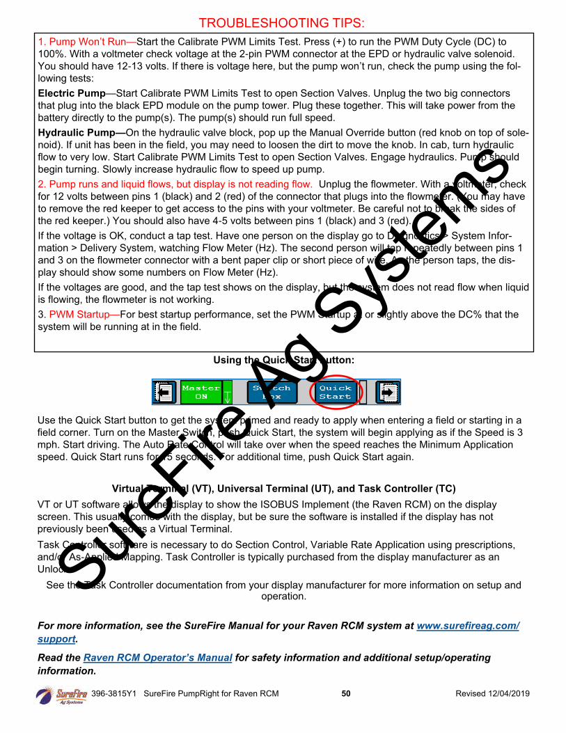
396-3815Y1 SureFire PumpRight for Raven RCM 50 Revised 12/04/2019
1. Pump Won’t Run—Start the Calibrate PWM Limits Test. Press (+) to run the PWM Duty Cycle (DC) to
100%. With a voltmeter check voltage at the 2-pin PWM connector at the EPD or hydraulic valve solenoid.
You should have 12-13 volts. If there is voltage here, but the pump won’t run, check the pump using the fol-
lowing tests:
Electric Pump—Start Calibrate PWM Limits Test to open Section Valves. Unplug the two big connectors
that plug into the black EPD module on the pump tower. Plug these together. This will take power from the
battery directly to the pump(s). The pump(s) should run full speed.
Hydraulic Pump—On the hydraulic valve block, pop up the Manual Override button (red knob on top of sole-
noid). If unit has been in the field, you may need to loosen the dirt to move the knob. In cab, turn hydraulic
flow to very low. Start Calibrate PWM Limits Test to open Section Valves. Engage hydraulics. Pump should
begin turning. Slowly increase hydraulic flow to speed up pump.
2. Pump runs and liquid flows, but display is not reading flow. Unplug the flowmeter. With a voltmeter, check
for 12 volts between pins 1 (black) and 2 (red) of the connector that plugs into the flowmeter. (You may have
to remove the red keeper to get access to the pins with your voltmeter. Be careful not to break the sides of
the red keeper.) You should also have 4-5 volts between pins 1 (black) and 3 (red).
If the voltage is OK, conduct a tap test. Have one person on the display go to Diagnostics > System Infor-
mation > Delivery System, watching Flow Meter (Hz). The second person will tap repeatedly between pins 1
and 3 on the flowmeter connector with a bent paper clip or short piece of wire. As the person taps, the dis-
play should show some numbers on Flow Meter (Hz).
If the voltages are good, and the tap test shows on the display, but the system does not read flow when liquid
is flowing, the flowmeter is not working.
3. PWM Startup—For best startup performance, set the PWM Startup at or slightly above the DC% that the
system will be running at in the field.
TROUBLESHOOTING TIPS:
Using the Quick Start button:
Use the Quick Start button to get the system primed and ready to apply when entering a field or starting in a
field corner. Turn on the Master Switch, push Quick Start, the system will begin applying as if the Speed is 3
mph. Start driving. The Auto Rate Control will take over when the speed reaches the Minimum Application
speed. Quick Start runs for 15 seconds. For additional time, push Quick Start again.
Virtual Terminal (VT), Universal Terminal (UT), and Task Controller (TC)
VT or UT software allows the display to show the ISOBUS Implement (the Raven RCM) on the display
screen. This usually comes with the display, but be sure the software is installed if the display has not
previously been used as a Virtual Terminal.
Task Controller software is necessary to do Section Control, Variable Rate Application using prescriptions,
and/or As-Applied Mapping. Task Controller is typically purchased from the display manufacturer as an
Unlock.
See the Task Controller documentation from your display manufacturer for more information on setup and operation.
For more information, see the SureFire Manual for your Raven RCM system at www.surefireag.com/
support.
Read the Raven RCM Operator’s Manual for safety information and additional setup/operating
information.
SureFire
Ag Sys
tems
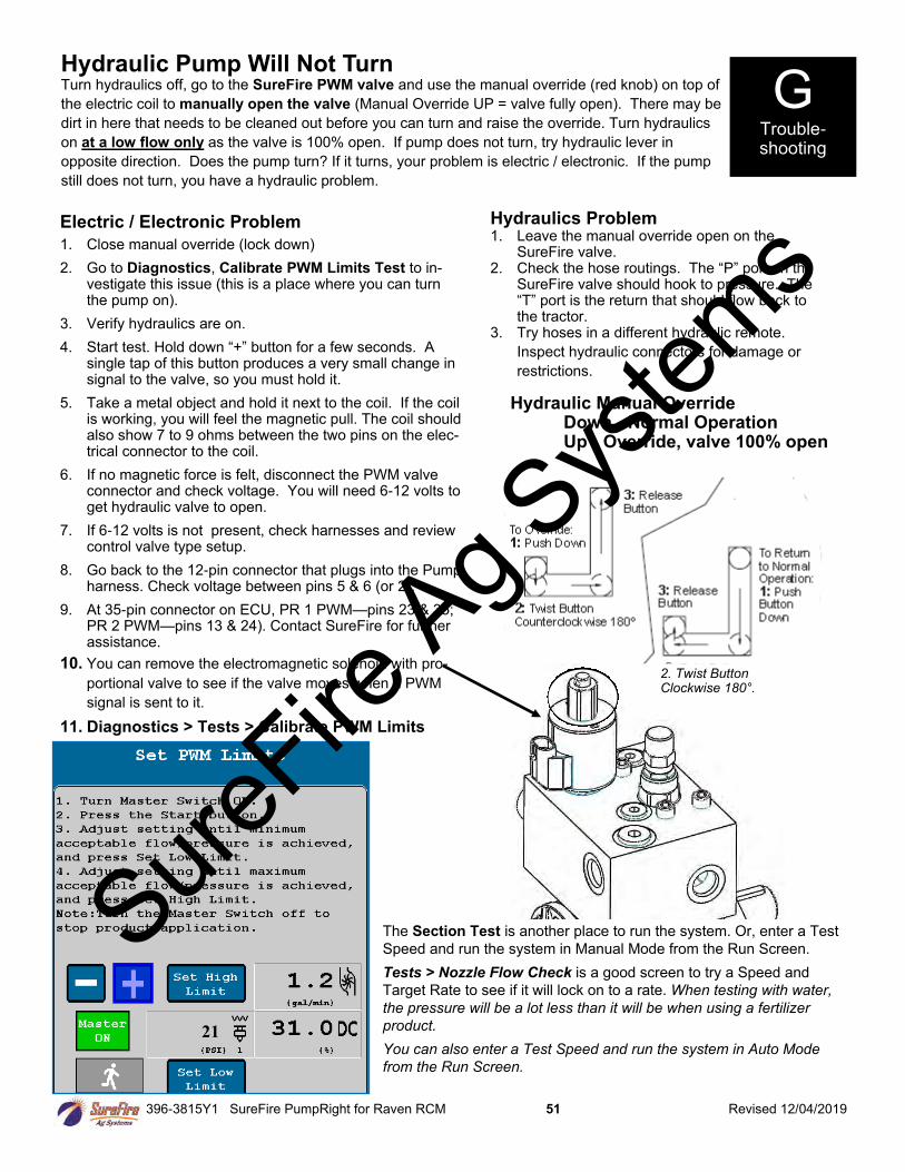
396-3815Y1 SureFire PumpRight for Raven RCM 51 Revised 12/04/2019
Hydraulic Pump Will Not Turn Turn hydraulics off, go to the SureFire PWM valve and use the manual override (red knob) on top of
the electric coil to manually open the valve (Manual Override UP = valve fully open). There may be
dirt in here that needs to be cleaned out before you can turn and raise the override. Turn hydraulics
on at a low flow only as the valve is 100% open. If pump does not turn, try hydraulic lever in
opposite direction. Does the pump turn? If it turns, your problem is electric / electronic. If the pump
still does not turn, you have a hydraulic problem.
Electric / Electronic Problem
1. Close manual override (lock down)
2. Go to Diagnostics, Calibrate PWM Limits Test to in-vestigate this issue (this is a place where you can turn the pump on).
3. Verify hydraulics are on.
4. Start test. Hold down “+” button for a few seconds. A single tap of this button produces a very small change in signal to the valve, so you must hold it.
5. Take a metal object and hold it next to the coil. If the coil is working, you will feel the magnetic pull. The coil should also show 7 to 9 ohms between the two pins on the elec-trical connector to the coil.
6. If no magnetic force is felt, disconnect the PWM valve connector and check voltage. You will need 6-12 volts to get hydraulic valve to open.
7. If 6-12 volts is not present, check harnesses and review control valve type setup.
8. Go back to the 12-pin connector that plugs into the Pump harness. Check voltage between pins 5 & 6 (or 2).
9. At 35-pin connector on ECU, PR 1 PWM—pins 23 & 35; PR 2 PWM—pins 13 & 24). Contact SureFire for further assistance.
10. You can remove the electromagnetic solenoid with pro-
portional valve to see if the valve moves when a PWM
signal is sent to it.
11. Diagnostics > Tests > Calibrate PWM Limits
Hydraulics Problem 1. Leave the manual override open on the
SureFire valve. 2. Check the hose routings. The “P” port on the
SureFire valve should hook to pressure. The “T” port is the return that should flow back to the tractor.
3. Try hoses in a different hydraulic remote.
Inspect hydraulic connectors for damage or
restrictions.
Hydraulic Manual Override Down - Normal Operation Up - Override, valve 100% open
The Section Test is another place to run the system. Or, enter a Test
Speed and run the system in Manual Mode from the Run Screen.
Tests > Nozzle Flow Check is a good screen to try a Speed and
Target Rate to see if it will lock on to a rate. When testing with water,
the pressure will be a lot less than it will be when using a fertilizer
product.
You can also enter a Test Speed and run the system in Auto Mode
from the Run Screen.
G Trouble-shooting
Tests > Calibrate
21
2. Twist Button Clockwise 180°.
SureFire
Ag Sys
tems
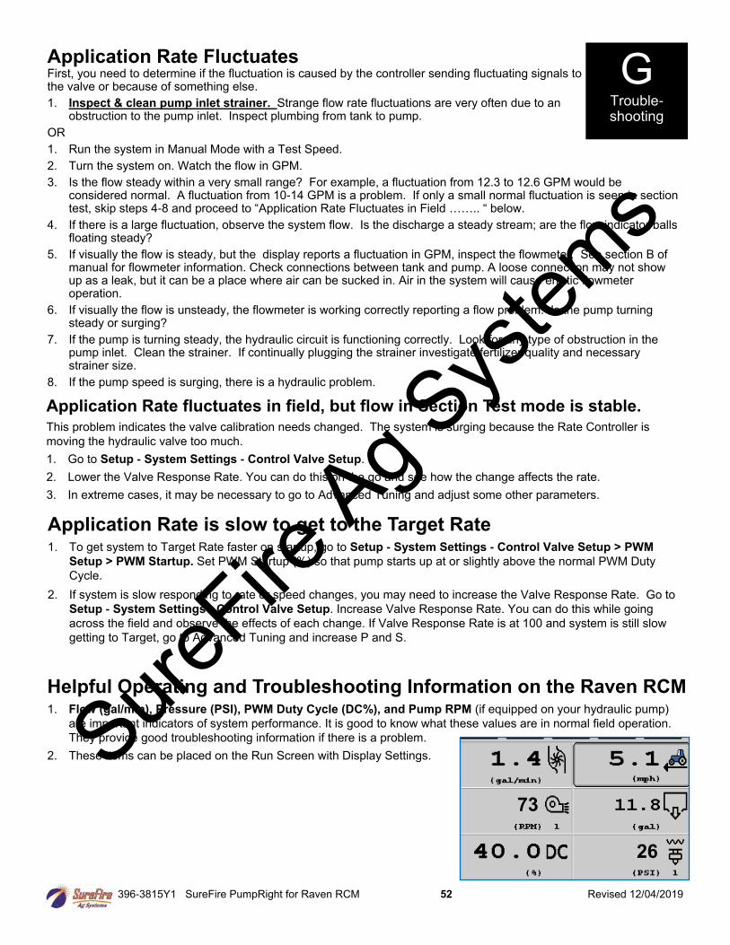
396-3815Y1 SureFire PumpRight for Raven RCM 52 Revised 12/04/2019
Application Rate Fluctuates First, you need to determine if the fluctuation is caused by the controller sending fluctuating signals to the valve or because of something else.
1. Inspect & clean pump inlet strainer. Strange flow rate fluctuations are very often due to an obstruction to the pump inlet. Inspect plumbing from tank to pump.
OR
1. Run the system in Manual Mode with a Test Speed.
2. Turn the system on. Watch the flow in GPM.
3. Is the flow steady within a very small range? For example, a fluctuation from 12.3 to 12.6 GPM would be considered normal. A fluctuation from 10-14 GPM is a problem. If only a small normal fluctuation is seen in section test, skip steps 4-8 and proceed to “Application Rate Fluctuates in Field …….. “ below.
4. If there is a large fluctuation, observe the system flow. Is the discharge a steady stream; are the flow indicator balls floating steady?
5. If visually the flow is steady, but the display reports a fluctuation in GPM, inspect the flowmeter. See section B of manual for flowmeter information. Check connections between tank and pump. A loose connection may not show up as a leak, but it can be a place where air can be sucked in. Air in the system will cause erratic flowmeter operation.
6. If visually the flow is unsteady, the flowmeter is working correctly reporting a flow problem. Is the pump turning steady or surging?
7. If the pump is turning steady, the hydraulic circuit is functioning correctly. Look for any type of obstruction in the pump inlet. Clean the strainer. If continually plugging the strainer investigate fertilizer quality and necessary strainer size.
8. If the pump speed is surging, there is a hydraulic problem.
Application Rate fluctuates in field, but flow in Section Test mode is stable. This problem indicates the valve calibration needs changed. The system is surging because the Rate Controller is
moving the hydraulic valve too much.
1. Go to Setup - System Settings - Control Valve Setup.
2. Lower the Valve Response Rate. You can do this on the go and see how the change affects the rate.
3. In extreme cases, it may be necessary to go to Advanced Tuning and adjust some other parameters.
Application Rate is slow to get to the Target Rate 1. To get system to Target Rate faster on startup, go to Setup - System Settings - Control Valve Setup > PWM
Setup > PWM Startup. Set PWM Startup (%) so that pump starts up at or slightly above the normal PWM Duty
Cycle.
2. If system is slow responding to rate or speed changes, you may need to increase the Valve Response Rate. Go to
Setup - System Settings - Control Valve Setup. Increase Valve Response Rate. You can do this while going
across the field and observe the effects of each change. If Valve Response Rate is at 100 and system is still slow
getting to Target, go to Advanced Tuning and increase P and S.
Helpful Operating and Troubleshooting Information on the Raven RCM 1. Flow (gal/min), Pressure (PSI), PWM Duty Cycle (DC%), and Pump RPM (if equipped on your hydraulic pump)
are important indicators of system performance. It is good to know what these values are in normal field operation.
They provide good troubleshooting information if there is a problem.
2. These items can be placed on the Run Screen with Display Settings.
G Trouble-shooting
73
26
SureFire
Ag Sys
tems
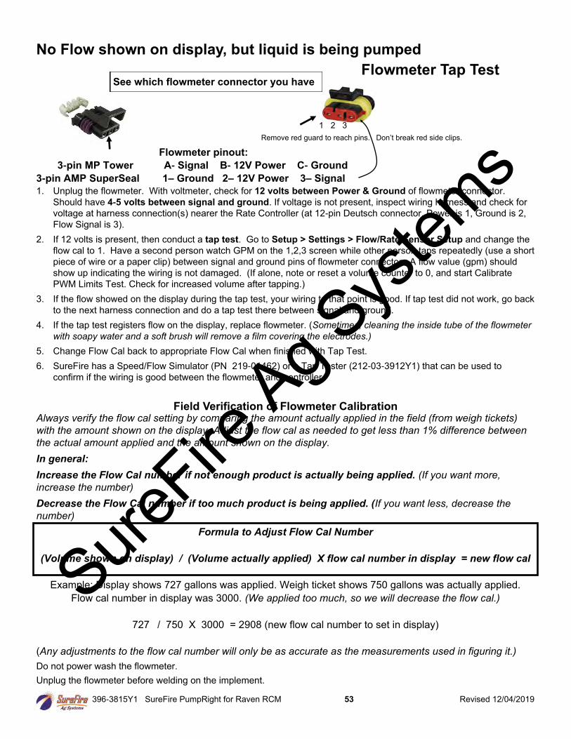
396-3815Y1 SureFire PumpRight for Raven RCM 53 Revised 12/04/2019
No Flow shown on display, but liquid is being pumped
Flowmeter Tap Test
Flowmeter pinout:
3-pin MP Tower A- Signal B- 12V Power C- Ground
3-pin AMP SuperSeal 1– Ground 2– 12V Power 3– Signal
1. Unplug the flowmeter. With voltmeter, check for 12 volts between Power & Ground of flowmeter connector.
Should have 4-5 volts between signal and ground. If voltage is not present, inspect wiring harness and check for
voltage at harness connection(s) nearer the Rate Controller (at 12-pin Deutsch connector, Power is 1, Ground is 2,
Flow Signal is 3).
2. If 12 volts is present, then conduct a tap test. Go to Setup > Settings > Flow/Rate Sensor Setup and change the
flow cal to 1. Have a second person watch GPM on the 1,2,3 screen while other person taps repeatedly (use a short
piece of wire or a paper clip) between signal and ground pins of flowmeter connector. A flow value (gpm) should
show up indicating the wiring is not damaged. (If alone, note or reset a volume counter to 0, and start Calibrate
PWM Limits Test. Check for increased volume after tapping.)
3. If the flow showed on the display during the tap test, your wiring to that point is good. If tap test did not work, go back
to the next harness connection and do a tap test there between signal and ground.
4. If the tap test registers flow on the display, replace flowmeter. (Sometimes, cleaning the inside tube of the flowmeter
with soapy water and a soft brush will remove a film covering the electrodes.)
5. Change Flow Cal back to appropriate Flow Cal when finished with Tap Test.
6. SureFire has a Speed/Flow Simulator (PN 219-01462) or a Tap Tester (212-03-3912Y1) that can be used to
confirm if the wiring is good between the flowmeter and controller.
Field Verification of Flowmeter Calibration Always verify the flow cal setting by comparing the amount actually applied in the field (from weigh tickets)
with the amount shown on the display. Adjust the flow cal as needed to get less than 1% difference between
the actual amount applied and the amount shown on the display.
In general:
Increase the Flow Cal number if not enough product is actually being applied. (If you want more,
increase the number)
Decrease the Flow Cal number if too much product is being applied. (If you want less, decrease the
number)
Formula to Adjust Flow Cal Number
(Volume shown on display) / (Volume actually applied) X flow cal number in display = new flow cal
Example: Display shows 727 gallons was applied. Weigh ticket shows 750 gallons was actually applied.
Flow cal number in display was 3000. (We applied too much, so we will decrease the flow cal.)
727 / 750 X 3000 = 2908 (new flow cal number to set in display)
(Any adjustments to the flow cal number will only be as accurate as the measurements used in figuring it.)
Do not power wash the flowmeter.
Unplug the flowmeter before welding on the implement.
Remove red guard to reach pins. Don’t break red side clips.
See which flowmeter connector you have
1 2 3
SureFire
Ag Sys
tems
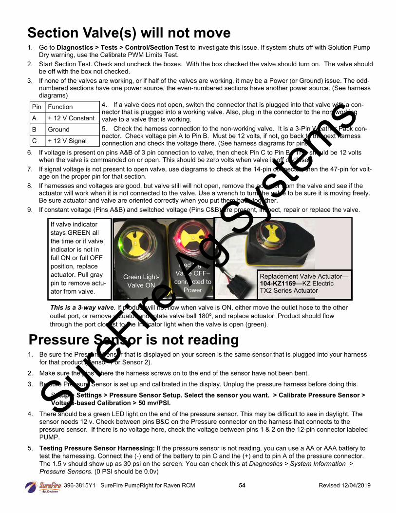
396-3815Y1 SureFire PumpRight for Raven RCM 54 Revised 12/04/2019
1. Be sure the Pressure Sensor that is displayed on your screen is the same sensor that is plugged into your harness
for that product (Sensor 1 or Sensor 2).
2. Make sure the pins where the harness screws on to the end of the sensor have not been bent.
3. Be sure Pressure Sensor is set up and calibrated in the display. Unplug the pressure harness before doing this.
Setup > Settings > Pressure Sensor Setup. Select the sensor you want. > Calibrate Pressure Sensor >
Voltage-based Calibration > 50 mv/PSI.
4. There should be a green LED light on the end of the pressure sensor. This may be difficult to see in daylight. The
sensor needs 12 v. Check between pins B&C on the Pressure connector on the harness that connects to the
pressure sensor. If there is no voltage here, check the voltage between pins 1 & 2 on the 12-pin connector labeled
PUMP.
5. Testing Pressure Sensor Harnessing: If the pressure sensor is not reading, you can use a AA or AAA battery to
test the harnessing. Connect the (-) end of the battery to pin C and the (+) end to pin A of the pressure connector.
The 1.5 v should show up as 30 psi on the screen. You can check this at Diagnostics > System Information >
Pressure Sensors. (0 PSI should be 0.0v)
Pressure Sensor is not reading
Section Valve(s) will not move 1. Go to Diagnostics > Tests > Control/Section Test to investigate this issue. If system shuts off with Solution Pump
Dry warning, use the Calibrate PWM Limits Test.
2. Start Section Test. Check and uncheck the boxes. With the box checked the valve should turn on. The valve should be off with the box not checked.
3. If none of the valves are working, or if half of the valves are working, it may be a Power (or Ground) issue. The odd-numbered sections have one power source, the even-numbered sections have another power source. (See harness diagrams)
4. If a valve does not open, switch the connector that is plugged into that valve with a con-nector that is plugged into a working valve. Also, plug in the connector to the non-working valve to a valve that is working.
5. Check the harness connection to the non-working valve. It is a 3-Pin Weather Pack con-nector. Check voltage pin A to Pin B. Must be 12 volts, if not, go back to the next harness connection and check the voltage there. (See harness diagrams for pins)
6. If voltage is present on pins A&B of 3 pin connection to valve, then check Pin C to Pin B. This should be 12 volts when the valve is commanded on or open. This should be zero volts when valve is off or closed.
7. If signal voltage is not present to open valve, use diagrams to check at the 14-pin connector, then the 47-pin for volt-age on the proper pin for that section.
8. If harnesses and voltages are good, but valve still will not open, remove the actuator from the valve and see if the actuator will work when it is not connected to the valve. Use a wrench to turn the valve to be sure it is moving freely. Be sure actuator and valve are oriented correctly when you put them back together.
9. If constant voltage (Pins A&B) and switched voltage (Pins C&B) are present, inspect, repair or replace the valve.
Pin Function
A + 12 V Constant
B Ground
C + 12 V Signal
Green Light-
Valve ON
Red Light
Valve OFF–
connected to
Power
If valve indicator
stays GREEN all
the time or if valve
indicator is not in
full ON or full OFF
position, replace
actuator. Pull gray
pin to remove actu-
ator from valve.
Replacement Valve Actuator—104-KZ1169—KZ Electric TX2 Series Actuator
This is a 3-way valve. If product will not flow when valve is ON, either move the outlet hose to the other
outlet port, or remove actuator and rotate valve ball 180º, and replace actuator. Product should flow
through the port closest to the Indicator light when the valve is open (green).
SureFire
Ag Sys
tems
396-3815Y1 SureFire PumpRight for Raven RCM 55 Revised 12/04/2019
Other issues 1. “My rate won’t go low enough. I want 8 gpa, but it won’t put down less
than 11 gpa.”
A. Check Setup > System Settings > Rates > Minimum Flow Rate. This can be set at
0.0 or at the low range of your flowmeter. This is gal / min not gal / acre.
B. Check Setup > System Settings > Control Valve Setup > PWM Settings > Low Limit. Default setting is
10 for electric pumps and 25-30 for hydraulic pumps. If set too high, the pump cannot slow down enough
when your speed drops or when sections close.
C. On a hydraulic pump, be sure the red manual override knob is down and locked on the hydraulic valve.
2. “I can’t get up to my rate. I want 12 gpa, and I can’t get more than 10 gpa.”
A. How many GPM are required to hit your rate? Is this within the pump’s specifications? On an electric
pump, the output of the pump decreases as the pressure increases. Keep the pressure under 40 PSI (or
lower) on an electric system. Is a recirculation valve open, allowing too much liquid to recirculate?
B. On a dual electric pump system, check each pump individually to see that each one is working at
capacity.
C. Is the strainer plugged? If too small of a mesh strainer is being used, the fluid can gel up around the
screen as the fluid is pulled through.
D. Does the pump have enough hydraulic oil to hit the desired rate? If the pump is in series behind another
pump or motor, the hydraulic oil to this pump may be limited.
E. Check Setup > System Settings > Control Valve Setup > PWM Setup > PWM Settings > High Limit.
This should be 100.
F. Check the PWM DC % (Duty Cycle). This can be placed on the Run Screen.
G. Check the Pump RPM. Maximum RPM should be 500-550 RPM.
H. Run the pump with a Test Speed in Manual Mode. Press the + button to increase flow. Observe flow
(GPM), PWM DC%, PSI, and Pump RPM (if equipped).
I. Run a Nozzle Flow Check. See gal/ac, PSI, gal/min, and PWM Duty Cycle.
J. Is the flow cal correct? Is the width of the implement set correctly?
3. “It’s pretty close to the rate, but it won’t ever lock in to the rate.”
Go to Setup > System Settings > Rates > Display Smoothing. Check the box for Display Smoothing.
Without Display Smoothing it is normal for the system to show the rate constantly changing small amounts as
you go across the field. With Display Smoothing, if the Applied Rate is close to the Target Rate, the display
does not show all the small changes.
4. “When I start up, I get a screen that says “Solution Pump Dry”.
This is not unusual on the RCM. If the flowmeter does not show flow immediately when you start, this screen
pops up. It is made to protect centrifugal pumps that can be harmed quickly if they are dry. This is not a
problem for SureFire diaphragm pumps. To get to Target Rate quicker on startup, set the PWM Startup % so
the pump starts at or near where it will be running.
G Trouble-shooting
SureFire
Ag Sys
tems
396-3815Y1 SureFire PumpRight for Raven RCM 56 Revised 12/04/2019
5. “My pressure is too high / too low.”
The pressure will be what it is depending on how hard it has to push to get the amount of liquid you
are moving from the pressure sensor to where it leaves the system. This pressure will depend on the
product itself, the volume (gal/min) you are moving and how much restriction there is to that flow. The
orifice or metering tube will be the primary restriction, but it is possible that other parts of the system
may add to the total pressure. The pressure a system develops will be less (possibly much less) with water than it will be
with a fertilizer product.
What pressure is “too low”?
You need enough pressure to open the check valves. If the pressure is too low, some check valves will open before
others, so that some rows may be flowing while others are not. With 4 lb check valves, we like at least 8 PSI. With 10
lb check valves, we like 15-20 PSI.
What pressure is “too high”?
There are a few products that may have flow characteristics that are better at lower rather than higher pressures. With
most products that is not a concern.
The plumbing components of a SureFire system are rated at 100 PSI or above. On an electric pump system, the pump
capacity decreases as the pressure increases. Our standard Tower pump has an internal 70 PSI bypass. With an
electric pump, we like to see pressures from 10 to 30 PSI. If the pump has the capacity to hit the rate at higher
pressures, there is not a problem with doing that, but for long-term operation it would be best to switch to a larger orifice
or metering tube.
The SureFire PumpRight hydraulic pump has the ability to pump up to 290 PSI. SureFire plumbs these with a 100 PSI
pressure relief valve (PRV) so that plumbing components will not be damaged if high pressure develops. Typical
operating pressures with hydraulic pumps will be 20-60 PSI, but the pump will work fine at 80-90 PSI if that is
needed. If continually running in that high range, consider a larger orifice or metering tube.
Lower pressure will not necessarily reduce the velocity of the output stream at the row. Conversely, higher pressure
will not necessarily increase the velocity of the output stream at the row. The velocity of the output stream is determined
by the volume of the flow and the size of the opening at the output. Changing the pressure by changing an orifice or
metering tube upstream from the outlet will not affect the velocity of the output stream if the flow volume remains the
same.
Options if pressure is too high with orifices: Use a bigger orifice. Slow down. If pressure is too low, use a
smaller orifice.
With metering tube: Options if pressure is too high: Use a larger diameter tube. Shorten the tubes that are
on now. Slow down. (The pressure in a metering tube is related to the viscosity of the product. Many products change
viscosity as the temperature changes. A product will have a higher viscosity (and therefore higher pressure) on a cold
morning that it will on a hot afternoon.)
With metering tube: Options if pressure is too low: Switch to a smaller diameter tube. Use a longer tube.
See SureFire publication “396-3269Y1 Navigating the Metering Tube Maze” for more information on how
metering tube works.
See SureFire publication “396-3229Y1 Liquid System Components Overview” for a description of all the system
components and additional troubleshooting/service information.
See the system manual for your system for more complete information. Manuals and publications are available
for download at www.surefireag.com.
© 2016-2018 SureFire Ag Systems
G Trouble-shooting
Read the Raven RCM Operator’s Manual for safety information and additional setup/operating information. SureFire
Ag Sys
tems
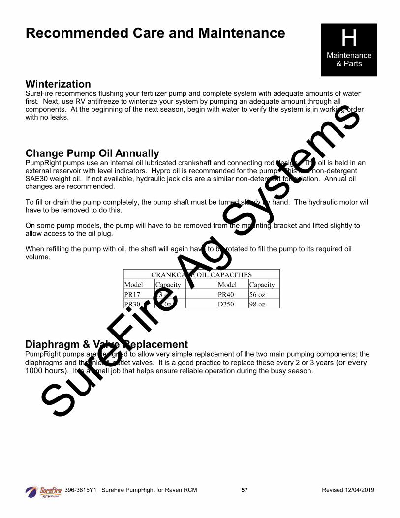
396-3815Y1 SureFire PumpRight for Raven RCM 57 Revised 12/04/2019
Winterization SureFire recommends flushing your fertilizer pump and complete system with adequate amounts of water first. Next, use RV antifreeze to winterize your system by pumping an adequate amount through all components. At the beginning of the next season, begin with water to verify the system is in working order with no leaks.
Change Pump Oil Annually PumpRight pumps use an internal oil lubricated crankshaft and connecting rod design. The oil is held in an external reservoir with level indicators. Hypro oil is recommended for the pump. This is a non-detergent SAE30 weight oil. If not available, hydraulic jack oils are a similar non-detergent formulation. Annual oil changes are recommended. To fill or drain the pump completely, the pump shaft must be turned slowly by hand. The hydraulic motor will have to be removed to do this. On some pump models, the pump will have to be removed from the mounting bracket and lifted slightly to allow access to the oil plug. When refilling the pump with oil, the shaft will again have to be rotated to fill the pump to its required oil volume.
Recommended Care and Maintenance H Maintenance
& Parts
Diaphragm & Valve Replacement PumpRight pumps are designed to allow very simple replacement of the two main pumping components; the
diaphragms and the inlet & outlet valves. It is a good practice to replace these every 2 or 3 years (or every 1000 hours). It is a small job that helps ensure reliable operation during the busy season.
CRANKCASE OIL CAPACITIES
Model Capacity Model Capacity
PR17 13 oz PR40 56 oz
PR30 28 0z D250 98 oz
SureFire
Ag Sys
tems
396-3815Y1 SureFire PumpRight for Raven RCM 58 Revised 12/04/2019
Pre-season Service
(A little time spent here may prevent some downtime when you want to be rolling.)
1. Visually check entire system (hoses, fittings, harnesses, etc.) for any signs of wear or trouble.
2. On the display, recheck all setup screens (see Section F) to verify correct setup.
3. Fill system with water and run in Manual mode (Section Test or Calibrate PWM Limits Test) to verify components and system are in working order. (May need to open air bleed valve to prime pump the first time. Be sure air bleed tube is not plugged.)
4. Clean out the dirt that may be packed in to the manual override knob on the hydraulic valve block. Be sure manual override knob can be operated in case it is needed for troubleshooting. The knob should be pushed down and locked for normal operation.
5. If necessary run pump in manual override mode to check hydraulic setup (see page 37).
6. Tighten all clamps. Loose clamps may be evident by leaks on the output side of the system. Loose clamps from the tank to the pump are not always apparent, but can be sources of air getting into the system which can create issues.
7. Push in tubes at all Quick-Connect fittings so they are seated tightly. Tubes that are not fully seated are not always obvious, but may allow air in, which can cause check valves to leak.
8. Remove the black cap from the top of each check valve. Check the diaphragm to be sure it is intact and not gummed up with residue. Look under the diaphragm for debris. Compress the spring in the cap to be sure it moves freely. Carefully replace diaphragm and tighten cap.
9. Remove and clean the strainer. Be sure strainer is tightened securely so it will not suck air.
10. Be sure all rows are flowing and that all metering tubes/orifices are open. (Note: It will take a higher flow rate with water to create enough pressure to open all the check valves.)
11. Run the Nozzle Flow Check to verify that system will lock on to a Target Rate.
H Maintenance
& Parts
Hydraulic oil under extremely high pressure. Do not use hand or any other skin to check for or to stop hydraulic leaks. Be sure pressure is relieved before loosening hydraulic fittings. Replace worn hoses immediately. Seek medical care immediately if hydraulic oil is shot into the eye or the skin.
These pumps can deliver liquid at high pressure (290 PSI). Be sure the 100 PSI Pressure Relief Valve (PRV) is installed and functioning so system pressure will be kept under 100 PSI. Check hoses, hose clamps, and liquid fittings regularly and repair or replace loose connections. Sure
Fire Ag S
ystem
s
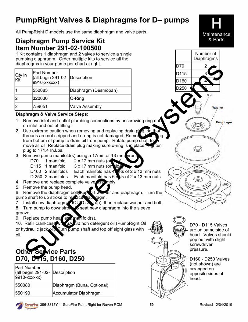
396-3815Y1 SureFire PumpRight for Raven RCM 59 Revised 12/04/2019
PumpRight Valves & Diaphragms for D– pumps
All PumpRight D-models use the same diaphragm and valve parts.
Number of Diaphragms
D70 2
D115 3
D160 4
D250 6
Diaphragm Pump Service Kit Item Number 291-02-100500 1 Kit contains 1 diaphragm and 2 valves to service a single pumping diaphragm. Order multiple kits to service all the diaphragms in your pump per chart at right.
Qty in Kit
Part Number (all begin 291-02-9910-xxxxxx)
Description
1 550085 Diaphragm (Desmopan)
2 320030 O-Ring
2 759051 Valve Assembly
Other Service Parts D70, D115, D160, D250
Part Number (all begin 291-02-9910-xxxxxx)
Description
550080 Diaphragm (Buna, Optional)
550190 Accumulator Diaphragm
Diaphragm & Valve Service Steps:
1. Remove inlet and outlet plumbing connections by unscrewing ring nut on inlet and outlet fitting.
2. Use extreme caution when removing and replacing drain plug, so that threads are not stripped and o-ring is not damaged. Remove drain plug from bottom of pump to drain oil from pump. Rotate pump shaft to re-move all oil. Replace drain plug making sure o-ring is in place. Tighten plug to 171.4 In.Lbs.
3. Remove pump manifold(s) using a 17mm or 13 mm wrench.
D70 1 manifold 2 x 17 mm nuts (on top)
D115 1 manifold 3 x 17 mm nuts (on side)
D160 2 manifolds Each manifold has 4 sets of 2 x 13 mm nuts
D 250 2 manifolds Each manifold has 6 sets of 2 x 13 mm nuts
4. Remove and replace complete valve assembly.
5. Remove the pump head.
6. Remove the diaphragm bolt, support washer and diaphragm. Turn the pump shaft to up stroke to replace diaphragm.
7. Install new diaphragm (LIQUID side up), then replace washer and bolt.
8. Turn pump to downstroke to seat new diaphragm into the sleeve groove.
9. Replace pump head and manifold(s).
10. Refill crankcase with SAE30 non detergent oil (PumpRight Oil
or hydraulic jack oil). Turn pump shaft and top off sight glass with
oil.
D70 - D115 Valves are on same side of head. Valves should pop out with slight screwdriver pressure. D160 - D250 Valves (not shown) are arranged on opposite sides of head.
H Maintenance
& Parts
SureFire
Ag Sys
tems
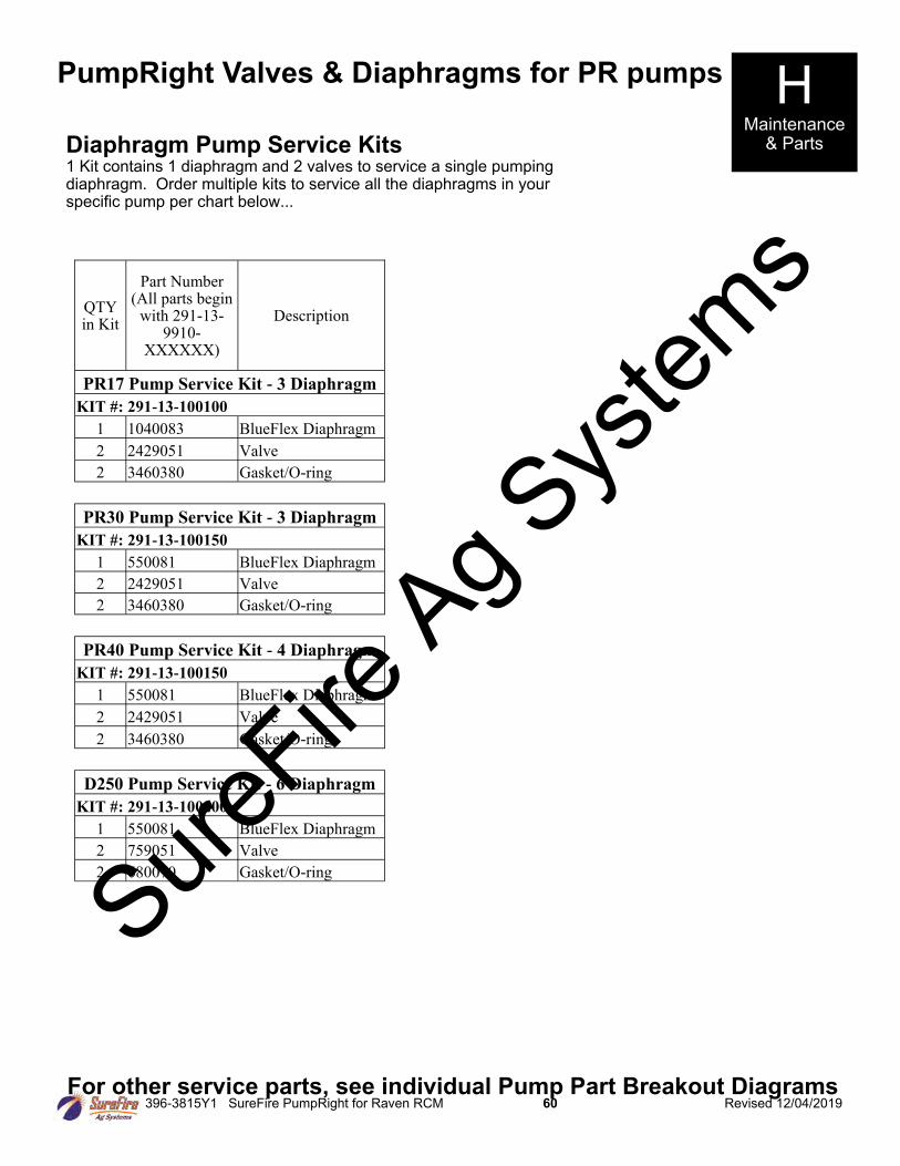
396-3815Y1 SureFire PumpRight for Raven RCM 60 Revised 12/04/2019
PumpRight Valves & Diaphragms for PR pumps
Diaphragm Pump Service Kits 1 Kit contains 1 diaphragm and 2 valves to service a single pumping diaphragm. Order multiple kits to service all the diaphragms in your specific pump per chart below...
For other service parts, see individual Pump Part Breakout Diagrams
H Maintenance
& Parts
QTY in Kit
Part Number (All parts begin
with 291-13-9910-
XXXXXX)
Description
PR17 Pump Service Kit - 3 Diaphragm
KIT #: 291-13-100100
1 1040083 BlueFlex Diaphragm
2 2429051 Valve
2 3460380 Gasket/O-ring
PR30 Pump Service Kit - 3 Diaphragm
KIT #: 291-13-100150
1 550081 BlueFlex Diaphragm
2 2429051 Valve
2 3460380 Gasket/O-ring
PR40 Pump Service Kit - 4 Diaphragm
KIT #: 291-13-100150
1 550081 BlueFlex Diaphragm
2 2429051 Valve
2 3460380 Gasket/O-ring
D250 Pump Service Kit - 6 Diaphragm
KIT #: 291-13-100200
1 550081 BlueFlex Diaphragm
2 759051 Valve
2 680070 Gasket/O-ring
SureFire
Ag Sys
tems
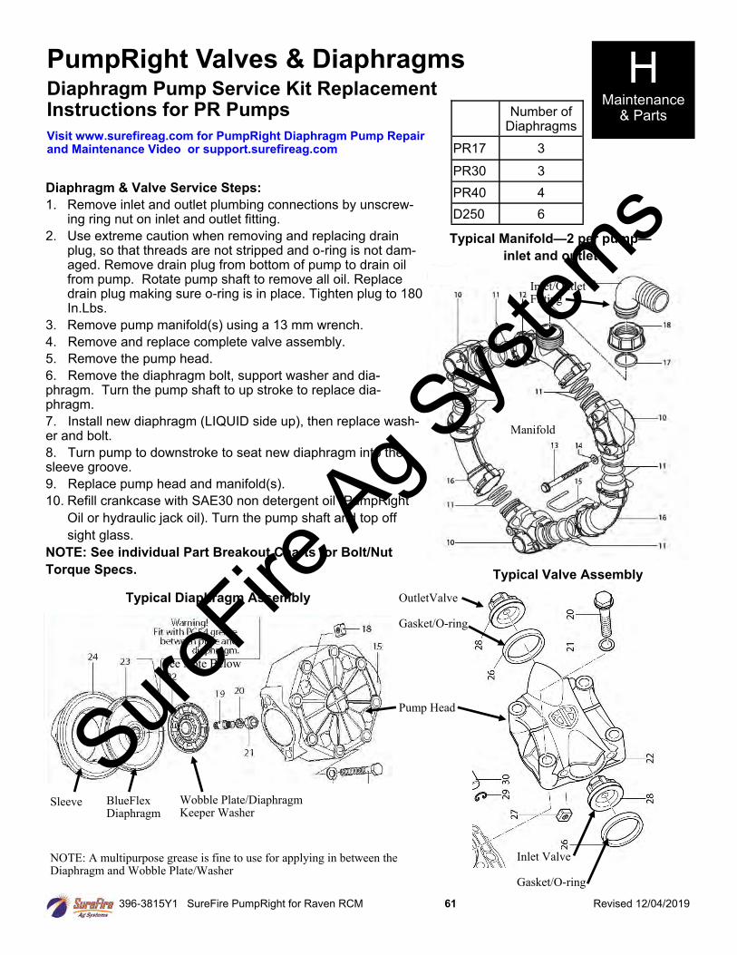
396-3815Y1 SureFire PumpRight for Raven RCM 61 Revised 12/04/2019
PumpRight Valves & Diaphragms
Number of Diaphragms
PR17 3
PR30 3
PR40 4
D250 6
Diaphragm Pump Service Kit Replacement Instructions for PR Pumps
Diaphragm & Valve Service Steps:
1. Remove inlet and outlet plumbing connections by unscrew-ing ring nut on inlet and outlet fitting.
2. Use extreme caution when removing and replacing drain plug, so that threads are not stripped and o-ring is not dam-aged. Remove drain plug from bottom of pump to drain oil from pump. Rotate pump shaft to remove all oil. Replace drain plug making sure o-ring is in place. Tighten plug to 180 In.Lbs.
3. Remove pump manifold(s) using a 13 mm wrench.
4. Remove and replace complete valve assembly.
5. Remove the pump head.
6. Remove the diaphragm bolt, support washer and dia-phragm. Turn the pump shaft to up stroke to replace dia-phragm.
7. Install new diaphragm (LIQUID side up), then replace wash-er and bolt.
8. Turn pump to downstroke to seat new diaphragm into the sleeve groove.
9. Replace pump head and manifold(s).
10. Refill crankcase with SAE30 non detergent oil (PumpRight
Oil or hydraulic jack oil). Turn the pump shaft and top off
sight glass.
NOTE: See individual Part Breakout Charts for Bolt/Nut
Torque Specs.
H Maintenance
& Parts
Typical Manifold—2 per pump—
inlet and outlet
Inlet/Outlet Fitting
Manifold
OutletValve Gasket/O-ring
Pump Head
Inlet Valve Gasket/O-ring
Typical Valve Assembly
Typical Diaphragm Assembly
Sleeve BlueFlex Diaphragm
Wobble Plate/Diaphragm Keeper Washer
Visit www.surefireag.com for PumpRight Diaphragm Pump Repair and Maintenance Video or support.surefireag.com
See Note Below
NOTE: A multipurpose grease is fine to use for applying in between the Diaphragm and Wobble Plate/Washer
SureFire
Ag Sys
tems
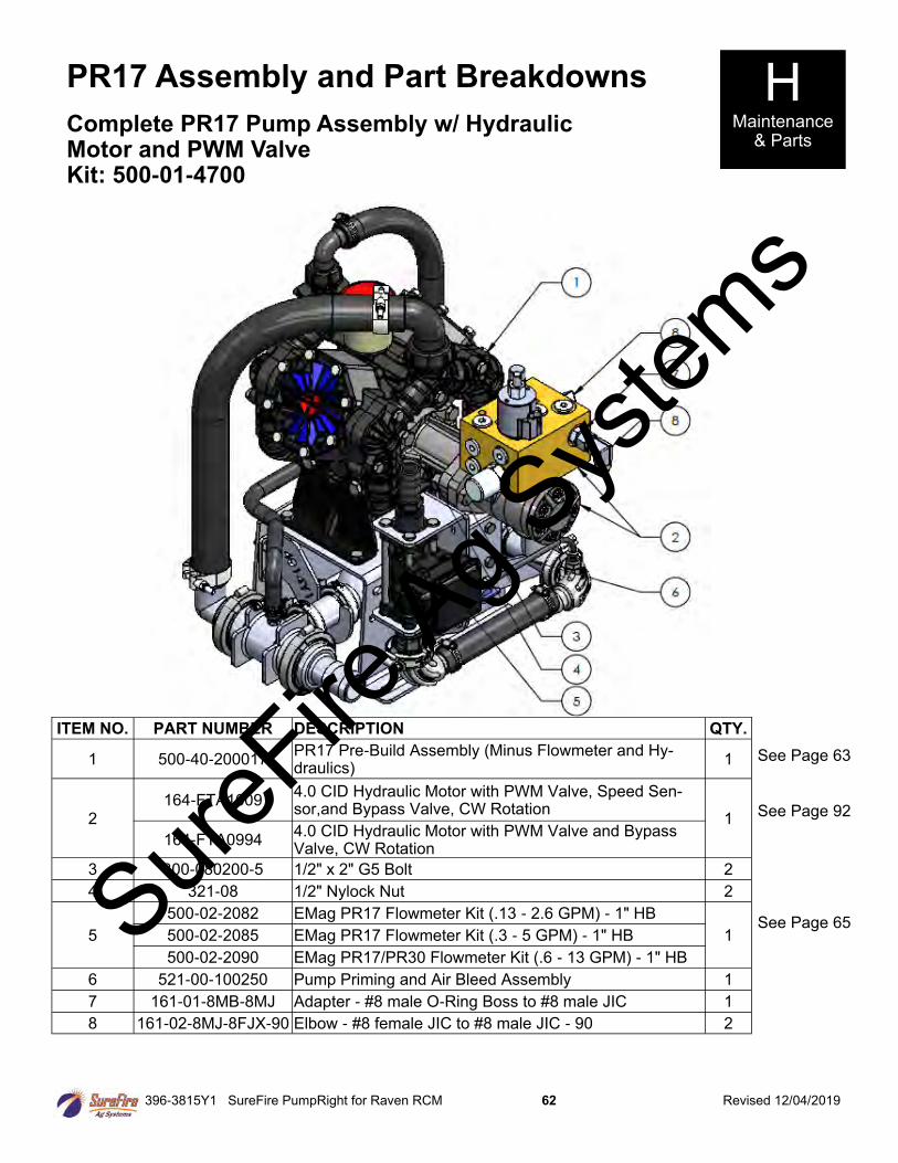
396-3815Y1 SureFire PumpRight for Raven RCM 62 Revised 12/04/2019
PR17 Assembly and Part Breakdowns H Maintenance
& Parts Complete PR17 Pump Assembly w/ Hydraulic Motor and PWM Valve Kit: 500-01-4700
ITEM NO. PART NUMBER DESCRIPTION QTY.
1 500-40-200017 PR17 Pre-Build Assembly (Minus Flowmeter and Hy-draulics)
1
2 164-FTA1609
4.0 CID Hydraulic Motor with PWM Valve, Speed Sen-sor,and Bypass Valve, CW Rotation
1
164-FTA0994 4.0 CID Hydraulic Motor with PWM Valve and Bypass Valve, CW Rotation
3 300-080200-5 1/2" x 2" G5 Bolt 2
4 321-08 1/2" Nylock Nut 2
5
500-02-2082 EMag PR17 Flowmeter Kit (.13 - 2.6 GPM) - 1" HB
1 500-02-2085 EMag PR17 Flowmeter Kit (.3 - 5 GPM) - 1" HB
500-02-2090 EMag PR17/PR30 Flowmeter Kit (.6 - 13 GPM) - 1" HB
6 521-00-100250 Pump Priming and Air Bleed Assembly 1
7 161-01-8MB-8MJ Adapter - #8 male O-Ring Boss to #8 male JIC 1
8 161-02-8MJ-8FJX-90 Elbow - #8 female JIC to #8 male JIC - 90 2
See Page 63
See Page 92
See Page 65 SureFire
Ag Sys
tems
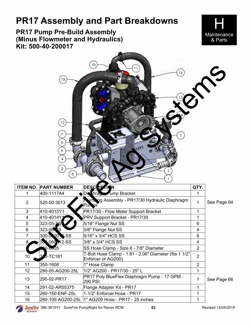
396-3815Y1 SureFire PumpRight for Raven RCM 63 Revised 12/04/2019
PR17 Assembly and Part Breakdowns H Maintenance
& Parts
PR17 Pump Pre-Build Assembly (Minus Flowmeter and Hydraulics) Kit: 500-40-200017
See Page 64
ITEM NO. PART NUMBER DESCRIPTION QTY.
1 400-1117A4 Diaphragm Pump Bracket 1
2 520-00-3013 Plumbing Assembly - PR17/30 Hydraulic Diaphragm Pumps
1
3 410-4015Y1 PR17/30 - Flow Meter Support Bracket 1
4 410-4014Y1 PRV Support Bracket - PR17/30 1
5 323-05-SS 5/16" Flange Nut SS 6
6 323-06-SS 3/8" Flange Nut SS 4
7 300-050012-SS 5/16" x 3/4" HCS SS 6
8 300-060012-SS 3/8" x 3/4" HCS SS 4
9 350-0605 SS Hose Clamp - Size 6 - 7/8" Diameter 2
10 350-TC181 T-Bolt Hose Clamp - 1.81 - 2.06" Diameter (fits 1 1/2" Enforcer or AG200)
2
11 350-1608 1" Hose Clamp 2
12 280-05-AG200-25L 1/2" AG200 - PR17/30 - 25" L 1
13 290-02-PR17 PR17 Poly BlueFlex Diaphragm Pump - 17 GPM - 290 PSI
1
14 291-02-AR55375 Flange Adapter Kit - PR17 1
15 280-150-ENF-25L 1-1/2" Enforcer Hose - PR17 1
16 280-100-AG200-25L 1" AG200 Hose - PR17 - 25 inches 1
See Page 66
SureFire
Ag Sys
tems
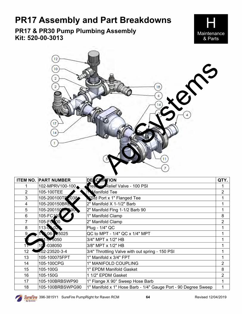
396-3815Y1 SureFire PumpRight for Raven RCM 64 Revised 12/04/2019
PR17 Assembly and Part Breakdowns H Maintenance
& Parts
PR17 & PR30 Pump Plumbing Assembly Kit: 520-00-3013
ITEM NO. PART NUMBER DESCRIPTION QTY.
1 102-MPRV100-100 Pressure Relief Valve - 100 PSI 1
2 105-100TEE 1" Manifold Tee 2
3 105-200100TEE038 2"Std Port x 1" Flanged Tee 1
4 105-200150BRB 2" Manifold X 1-1/2" Barb 1
5 105-200150BRB90 2" Manifold Flng 1-1/2 Barb 90 1
6 105-FC100 1" Manifold Clamp 8
7 105-FC200 2" Manifold Clamp 2
8 113-05-025 Plug - 1/4" QC 1
9 113-06-025025 QC to MPT - 1/4" QC x 1/4" MPT 1
10 101-075050 3/4" MPT x 1/2" HB 1
11 101-038050 3/8" MPT x 1/2" HB 1
12 102-23520-3-4 3/4" Throttling Valve with out spring - 150 PSI 1
13 105-100075FPT 1" Manifold x 3/4" FPT 1
14 105-100CPG 1" MANIFOLD COUPLING 2
15 105-100G 1" EPDM Manifold Gasket 8
16 105-150G 1 1/2" EPDM Gasket 2
17 105-100BRBSWP90 1" Flange X 90° Sweep Hose Barb 1
18 105-100BRBSWPG90 1" Manifold x 1" Hose Barb - 1/4" Gauge Port - 90 Degree Sweep 1
SureFire
Ag Sys
tems
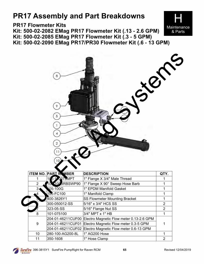
396-3815Y1 SureFire PumpRight for Raven RCM 65 Revised 12/04/2019
PR17 Assembly and Part Breakdowns H Maintenance
& Parts
PR17 Flowmeter Kits Kit: 500-02-2082 EMag PR17 Flowmeter Kit (.13 - 2.6 GPM) Kit: 500-02-2085 EMag PR17 Flowmeter Kit (.3 - 5 GPM) Kit: 500-02-2090 EMag PR17/PR30 Flowmeter Kit (.6 - 13 GPM)
ITEM NO. PART NUMBER DESCRIPTION QTY.
1 105-100075MPT 1" Flange X 3/4" Male Thread 1
2 105-100BRBSWP90 1" Flange X 90° Sweep Hose Barb 1
3 105-100G 1" EPDM Manifold Gasket 1
4 105-FC100 1" Manifold Clamp 1
5 400-3826Y1 SS Flowmeter Mounting Bracket 1
6 300-050012-SS 5/16" x 3/4" HCS SS 2
7 323-05-SS 5/16" Flange Nut SS 2
8 101-075100 3/4" MPT x 1" HB 1
9
204-01-46211CUF00 Electro Magnetic Flow meter 0.13-2.6 GPM
1 204-01-46211CUF01 Electro Magnetic Flow meter 0.3-5 GPM
204-01-46211CUF02 Electro Magnetic Flow meter 0.6-13 GPM
10 280-100-AG200-8L 1" AG200 Hose 1
11 350-1608 1" Hose Clamp 2
SureFire
Ag Sys
tems

396-3815Y1 SureFire PumpRight for Raven RCM 66 Revised 12/04/2019
H Maintenance
& Parts
PR17 Assembly and Part Breakdowns PR17 Polypropylene BlueFlex Diapragm Pump—17 GPM P/N: 290-02-PR17 (SP)
SureFire
Ag Sys
tems
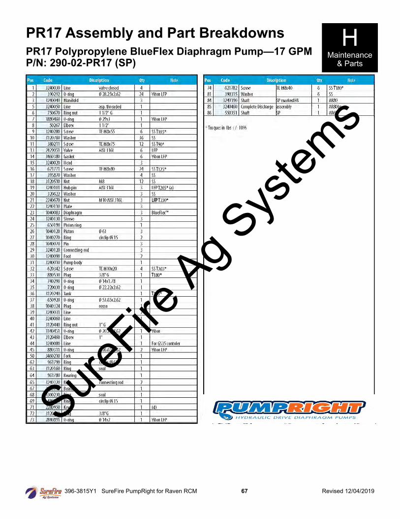
396-3815Y1 SureFire PumpRight for Raven RCM 67 Revised 12/04/2019
H Maintenance
& Parts
PR17 Assembly and Part Breakdowns
PR17 Polypropylene BlueFlex Diaphragm Pump—17 GPM P/N: 290-02-PR17 (SP)
SureFire
Ag Sys
tems
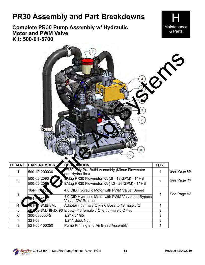
396-3815Y1 SureFire PumpRight for Raven RCM 68 Revised 12/04/2019
PR30 Assembly and Part Breakdowns H Maintenance
& Parts Complete PR30 Pump Assembly w/ Hydraulic Motor and PWM Valve Kit: 500-01-5700
See Page 69
See Page 71
See Page 92
ITEM NO. PART NUMBER DESCRIPTION QTY.
1 500-40-200030 PR30 Poly Pre-Build Assembly (Minus Flowmeter and Hydraulics)
1
2 500-02-2090 EMag PR30 Flowmeter Kit (.6 - 13 GPM) - 1" HB
1 500-02-2095 EMag PR30 Flowmeter Kit (1.3 - 26 GPM) - 1" HB
3 164-FTA1609 4.0 CID Hydraulic Motor with PWM Valve, Speed
1 164-FTA0994
4.0 CID Hydraulic Motor with PWM Valve and Bypass Valve, CW Rotation
4 161-01-8MB-8MJ Adapter - #8 male O-Ring Boss to #8 male JIC 1
5 161-02-8MJ-8FJX-90 Elbow - #8 female JIC to #8 male JIC - 90 2
6 300-080200-5 1/2" x 2" G5 2
7 321-08 1/2" Nylock Nut 2
8 521-00-100250 Pump Priming and Air Bleed Assembly 1
SureFire
Ag Sys
tems
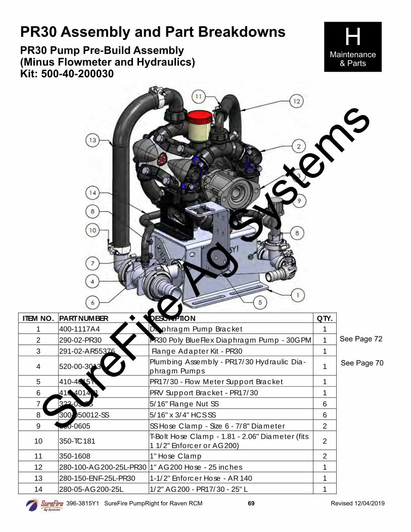
396-3815Y1 SureFire PumpRight for Raven RCM 69 Revised 12/04/2019
PR30 Assembly and Part Breakdowns H Maintenance
& Parts
PR30 Pump Pre-Build Assembly (Minus Flowmeter and Hydraulics) Kit: 500-40-200030
See Page 72
See Page 70
ITEM NO. PART NUMBER DESCRIPTION QTY.
1 400-1117A4 Diaphragm Pump Bracket 1
2 290-02-PR30 PR30 Poly BlueFlex Diaphragm Pump - 30GPM 1
3 291-02-AR55376 Flange Adapter Kit - PR30 1
4 520-00-3013 Plumbing Assembly - PR17/30 Hydraulic Dia-
phragm Pumps 1
5 410-4015Y1 PR17/30 - Flow Meter Support Bracket 1
6 410-4014Y1 PRV Support Bracket - PR17/30 1
7 323-05-SS 5/16" Flange Nut SS 6
8 300-050012-SS 5/16" x 3/4" HCS SS 6
9 350-0605 SS Hose Clamp - Size 6 - 7/8" Diameter 2
10 350-TC181 T-Bolt Hose Clamp - 1.81 - 2.06" Diameter (fits
1 1/2" Enforcer or AG200) 2
11 350-1608 1" Hose Clamp 2
12 280-100-AG200-25L-PR30 1" AG200 Hose - 25 inches 1
13 280-150-ENF-25L-PR30 1-1/2" Enforcer Hose - AR 140 1
14 280-05-AG200-25L 1/2" AG200 - PR17/30 - 25" L 1
SureFire
Ag Sys
tems
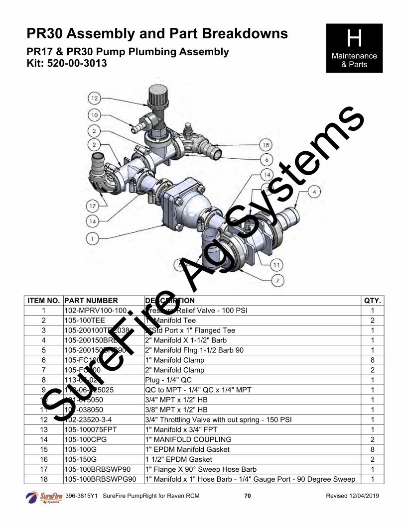
396-3815Y1 SureFire PumpRight for Raven RCM 70 Revised 12/04/2019
PR30 Assembly and Part Breakdowns H Maintenance
& Parts
PR17 & PR30 Pump Plumbing Assembly Kit: 520-00-3013
ITEM NO. PART NUMBER DESCRIPTION QTY.
1 102-MPRV100-100 Pressure Relief Valve - 100 PSI 1
2 105-100TEE 1" Manifold Tee 2
3 105-200100TEE038 2"Std Port x 1" Flanged Tee 1
4 105-200150BRB 2" Manifold X 1-1/2" Barb 1
5 105-200150BRB90 2" Manifold Flng 1-1/2 Barb 90 1
6 105-FC100 1" Manifold Clamp 8
7 105-FC200 2" Manifold Clamp 2
8 113-05-025 Plug - 1/4" QC 1
9 113-06-025025 QC to MPT - 1/4" QC x 1/4" MPT 1
10 101-075050 3/4" MPT x 1/2" HB 1
11 101-038050 3/8" MPT x 1/2" HB 1
12 102-23520-3-4 3/4" Throttling Valve with out spring - 150 PSI 1
13 105-100075FPT 1" Manifold x 3/4" FPT 1
14 105-100CPG 1" MANIFOLD COUPLING 2
15 105-100G 1" EPDM Manifold Gasket 8
16 105-150G 1 1/2" EPDM Gasket 2
17 105-100BRBSWP90 1" Flange X 90° Sweep Hose Barb 1
18 105-100BRBSWPG90 1" Manifold x 1" Hose Barb - 1/4" Gauge Port - 90 Degree Sweep 1
SureFire
Ag Sys
tems
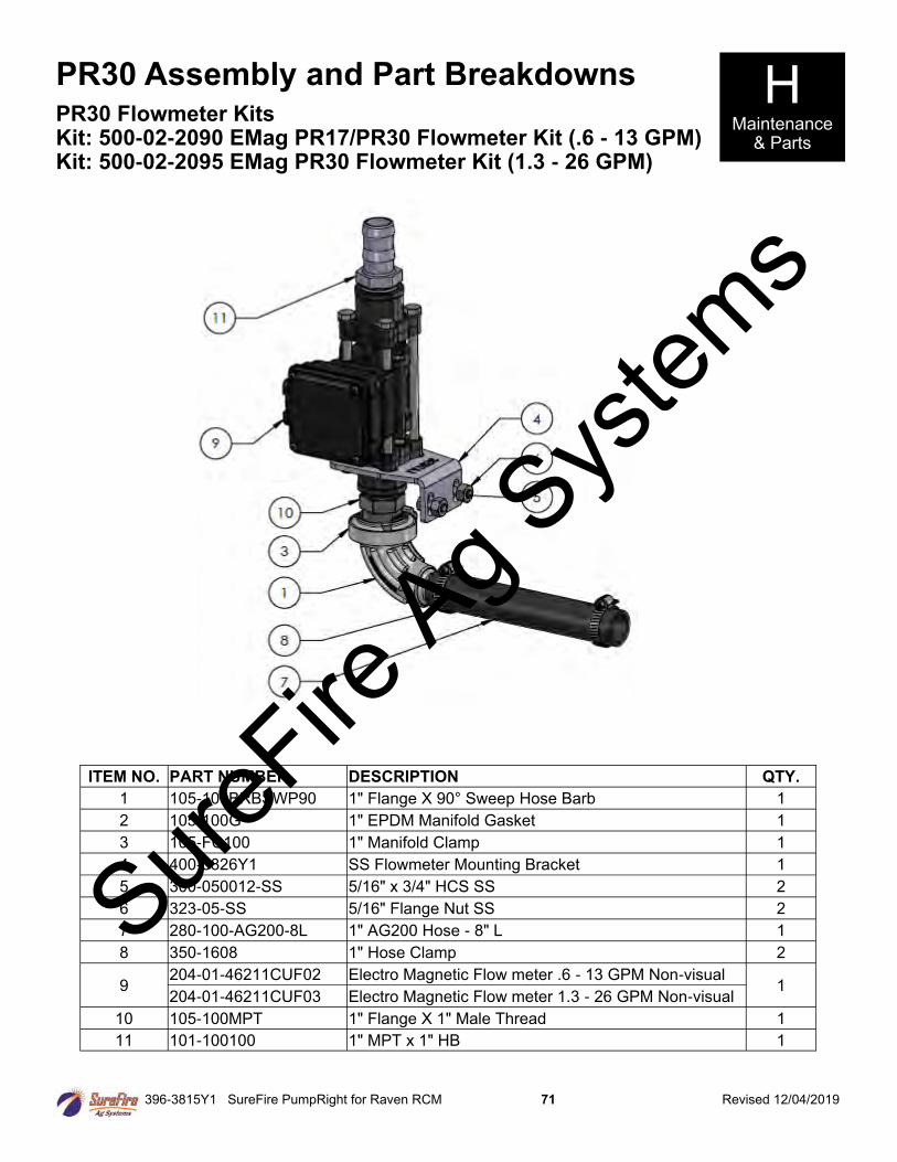
396-3815Y1 SureFire PumpRight for Raven RCM 71 Revised 12/04/2019
PR30 Assembly and Part Breakdowns H Maintenance
& Parts
PR30 Flowmeter Kits Kit: 500-02-2090 EMag PR17/PR30 Flowmeter Kit (.6 - 13 GPM) Kit: 500-02-2095 EMag PR30 Flowmeter Kit (1.3 - 26 GPM)
ITEM NO. PART NUMBER DESCRIPTION QTY.
1 105-100BRBSWP90 1" Flange X 90° Sweep Hose Barb 1
2 105-100G 1" EPDM Manifold Gasket 1
3 105-FC100 1" Manifold Clamp 1
4 400-3826Y1 SS Flowmeter Mounting Bracket 1
5 300-050012-SS 5/16" x 3/4" HCS SS 2
6 323-05-SS 5/16" Flange Nut SS 2
7 280-100-AG200-8L 1" AG200 Hose - 8" L 1
8 350-1608 1" Hose Clamp 2
9 204-01-46211CUF02 Electro Magnetic Flow meter .6 - 13 GPM Non-visual
1 204-01-46211CUF03 Electro Magnetic Flow meter 1.3 - 26 GPM Non-visual
10 105-100MPT 1" Flange X 1" Male Thread 1
11 101-100100 1" MPT x 1" HB 1
SureFire
Ag Sys
tems
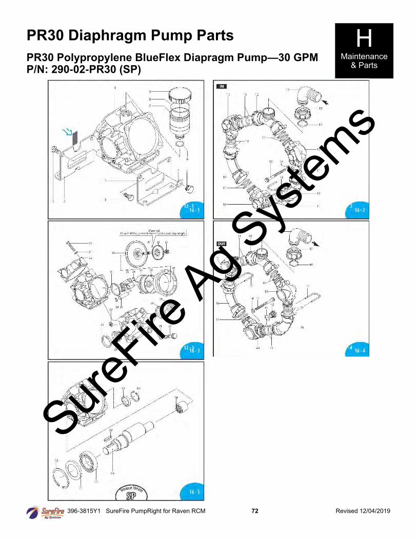
396-3815Y1 SureFire PumpRight for Raven RCM 72 Revised 12/04/2019
PR30 Diaphragm Pump Parts
PR30 Polypropylene BlueFlex Diapragm Pump—30 GPM P/N: 290-02-PR30 (SP)
H Maintenance
& Parts
SureFire
Ag Sys
tems
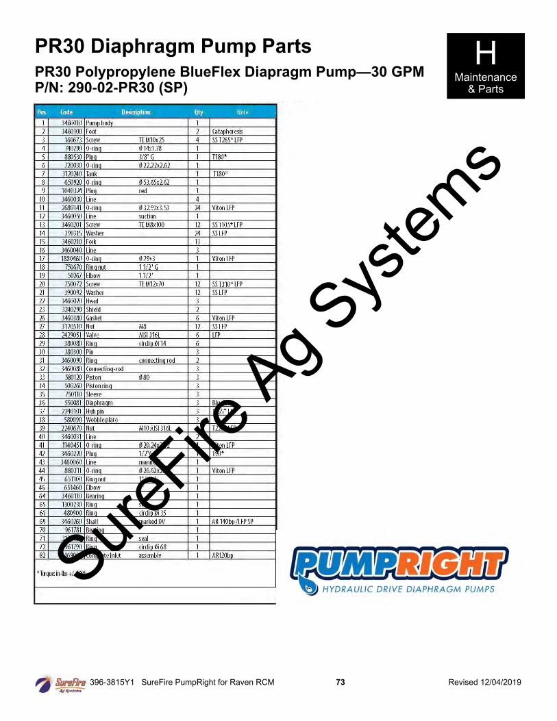
396-3815Y1 SureFire PumpRight for Raven RCM 73 Revised 12/04/2019
PR30 Diaphragm Pump Parts H Maintenance
& Parts
PR30 Polypropylene BlueFlex Diapragm Pump—30 GPM P/N: 290-02-PR30 (SP)
SureFire
Ag Sys
tems
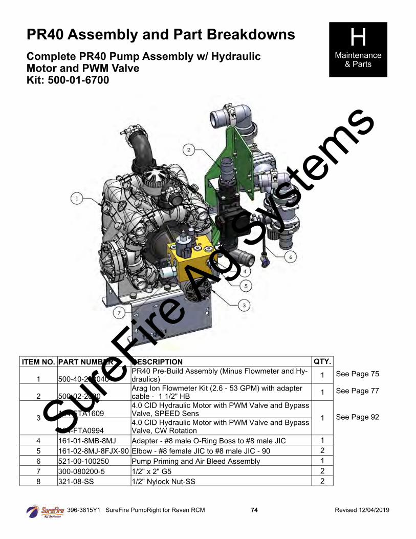
396-3815Y1 SureFire PumpRight for Raven RCM 74 Revised 12/04/2019
PR40 Assembly and Part Breakdowns H Maintenance
& Parts Complete PR40 Pump Assembly w/ Hydraulic Motor and PWM Valve Kit: 500-01-6700
See Page 75
See Page 77
See Page 92
ITEM NO. PART NUMBER DESCRIPTION QTY.
1 500-40-200040 PR40 Pre-Build Assembly (Minus Flowmeter and Hy-draulics)
1
2 500-02-2080 Arag Ion Flowmeter Kit (2.6 - 53 GPM) with adapter cable - 1 1/2" HB
1
3 164-FTA1609
4.0 CID Hydraulic Motor with PWM Valve and Bypass Valve, SPEED Sens
1
164-FTA0994 4.0 CID Hydraulic Motor with PWM Valve and Bypass Valve, CW Rotation
4 161-01-8MB-8MJ Adapter - #8 male O-Ring Boss to #8 male JIC 1
5 161-02-8MJ-8FJX-90 Elbow - #8 female JIC to #8 male JIC - 90 2
6 521-00-100250 Pump Priming and Air Bleed Assembly 1
7 300-080200-5 1/2" x 2" G5 2
8 321-08-SS 1/2" Nylock Nut-SS 2
SureFire
Ag Sys
tems
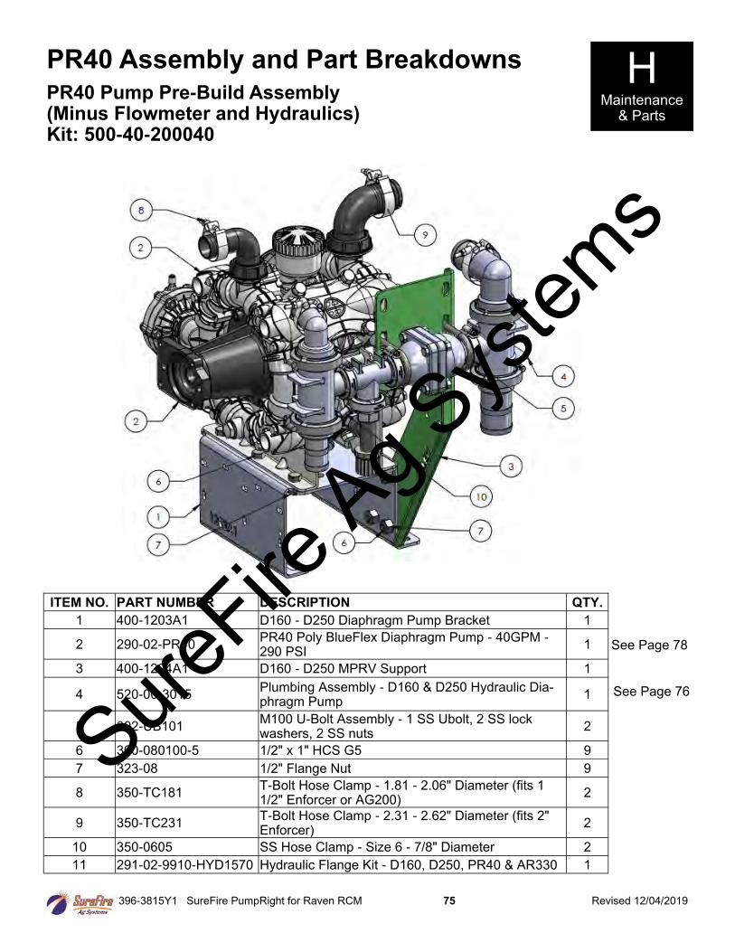
396-3815Y1 SureFire PumpRight for Raven RCM 75 Revised 12/04/2019
PR40 Assembly and Part Breakdowns H Maintenance
& Parts
PR40 Pump Pre-Build Assembly (Minus Flowmeter and Hydraulics) Kit: 500-40-200040
See Page 78
See Page 76
ITEM NO. PART NUMBER DESCRIPTION QTY.
1 400-1203A1 D160 - D250 Diaphragm Pump Bracket 1
2 290-02-PR40 PR40 Poly BlueFlex Diaphragm Pump - 40GPM - 290 PSI
1
3 400-1204A1 D160 - D250 MPRV Support 1
4 520-00-3015 Plumbing Assembly - D160 & D250 Hydraulic Dia-phragm Pump
1
5 302-UB101 M100 U-Bolt Assembly - 1 SS Ubolt, 2 SS lock washers, 2 SS nuts
2
6 300-080100-5 1/2" x 1" HCS G5 9
7 323-08 1/2" Flange Nut 9
8 350-TC181 T-Bolt Hose Clamp - 1.81 - 2.06" Diameter (fits 1 1/2" Enforcer or AG200)
2
9 350-TC231 T-Bolt Hose Clamp - 2.31 - 2.62" Diameter (fits 2" Enforcer)
2
10 350-0605 SS Hose Clamp - Size 6 - 7/8" Diameter 2
11 291-02-9910-HYD1570 Hydraulic Flange Kit - D160, D250, PR40 & AR330 1
SureFire
Ag Sys
tems
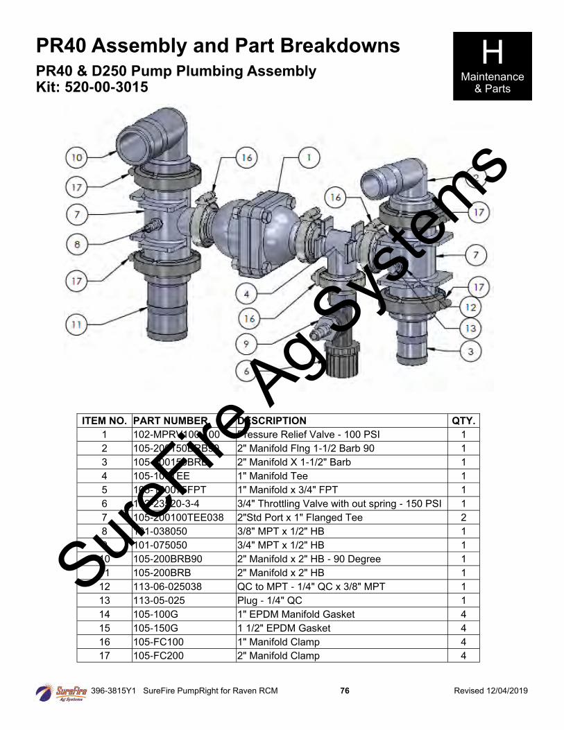
396-3815Y1 SureFire PumpRight for Raven RCM 76 Revised 12/04/2019
PR40 Assembly and Part Breakdowns H Maintenance
& Parts
PR40 & D250 Pump Plumbing Assembly Kit: 520-00-3015
ITEM NO. PART NUMBER DESCRIPTION QTY.
1 102-MPRV100-100 Pressure Relief Valve - 100 PSI 1
2 105-200150BRB90 2" Manifold Flng 1-1/2 Barb 90 1
3 105-200150BRB 2" Manifold X 1-1/2" Barb 1
4 105-100TEE 1" Manifold Tee 1
5 105-100075FPT 1" Manifold x 3/4" FPT 1
6 102-23520-3-4 3/4" Throttling Valve with out spring - 150 PSI 1
7 105-200100TEE038 2"Std Port x 1" Flanged Tee 2
8 101-038050 3/8" MPT x 1/2" HB 1
9 101-075050 3/4" MPT x 1/2" HB 1
10 105-200BRB90 2" Manifold x 2" HB - 90 Degree 1
11 105-200BRB 2" Manifold x 2" HB 1
12 113-06-025038 QC to MPT - 1/4" QC x 3/8" MPT 1
13 113-05-025 Plug - 1/4" QC 1
14 105-100G 1" EPDM Manifold Gasket 4
15 105-150G 1 1/2" EPDM Gasket 4
16 105-FC100 1" Manifold Clamp 4
17 105-FC200 2" Manifold Clamp 4
SureFire
Ag Sys
tems
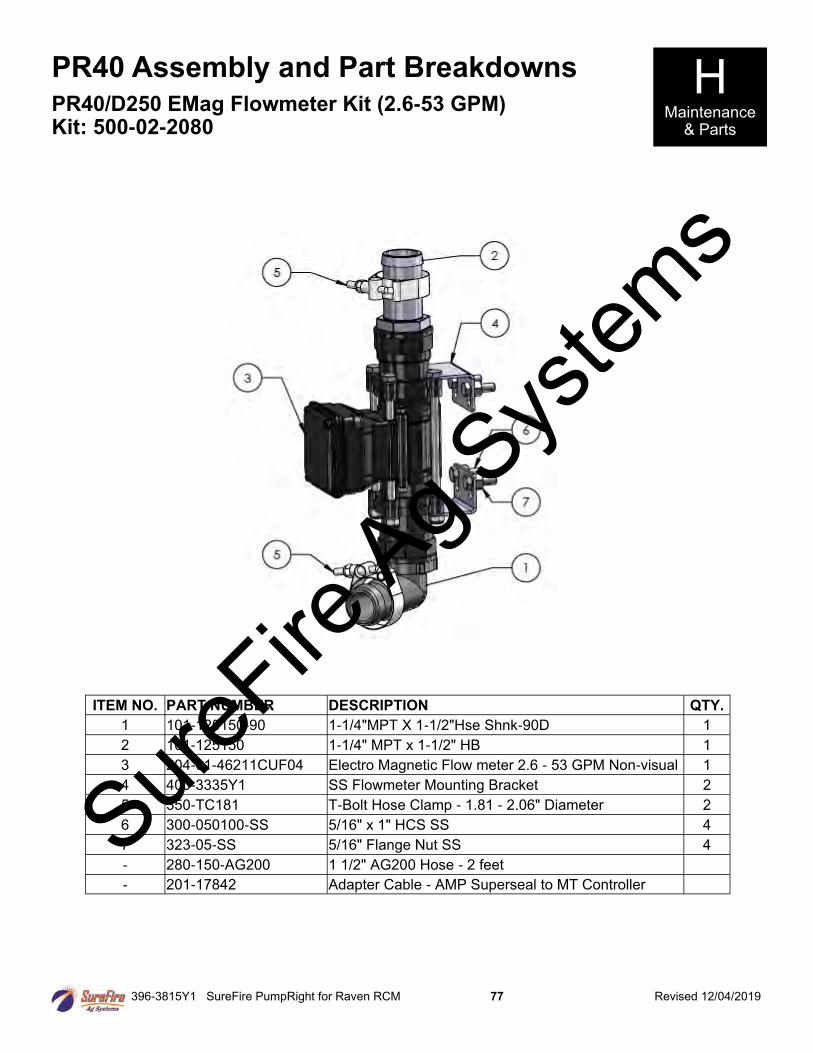
396-3815Y1 SureFire PumpRight for Raven RCM 77 Revised 12/04/2019
PR40 Assembly and Part Breakdowns H Maintenance
& Parts
PR40/D250 EMag Flowmeter Kit (2.6-53 GPM) Kit: 500-02-2080
ITEM NO. PART NUMBER DESCRIPTION QTY.
1 101-125150-90 1-1/4"MPT X 1-1/2"Hse Shnk-90D 1
2 101-125150 1-1/4" MPT x 1-1/2" HB 1
3 204-01-46211CUF04 Electro Magnetic Flow meter 2.6 - 53 GPM Non-visual 1
4 400-3335Y1 SS Flowmeter Mounting Bracket 2
5 350-TC181 T-Bolt Hose Clamp - 1.81 - 2.06" Diameter 2
6 300-050100-SS 5/16" x 1" HCS SS 4
7 323-05-SS 5/16" Flange Nut SS 4
- 280-150-AG200 1 1/2" AG200 Hose - 2 feet
- 201-17842 Adapter Cable - AMP Superseal to MT Controller
SureFire
Ag Sys
tems
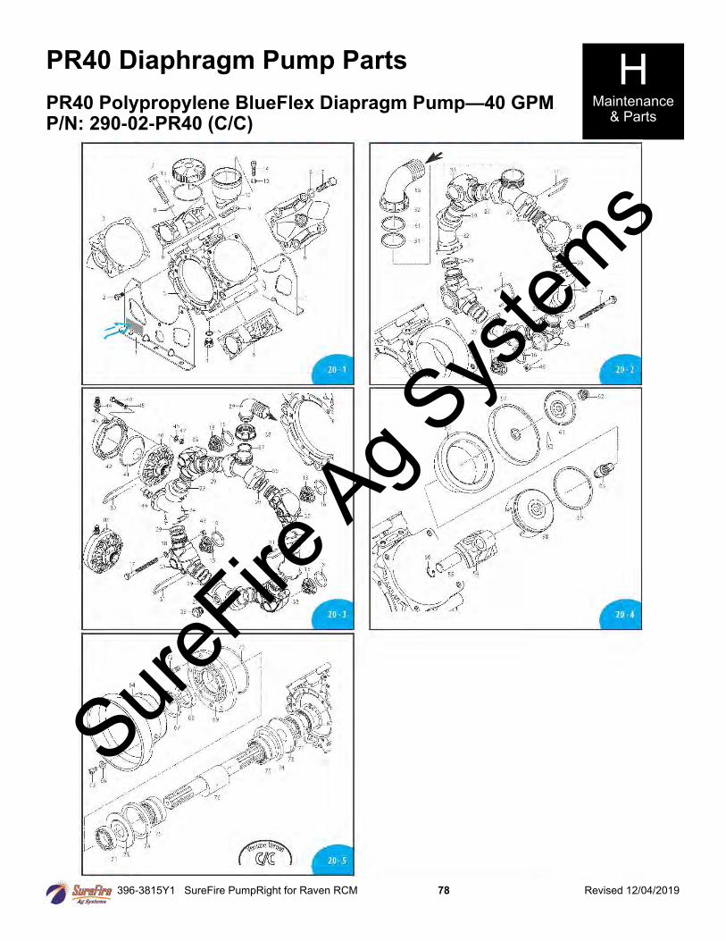
396-3815Y1 SureFire PumpRight for Raven RCM 78 Revised 12/04/2019
PR40 Diaphragm Pump Parts H Maintenance
& Parts PR40 Polypropylene BlueFlex Diapragm Pump—40 GPM P/N: 290-02-PR40 (C/C)
SureFire
Ag Sys
tems

396-3815Y1 SureFire PumpRight for Raven RCM 79 Revised 12/04/2019
PR40 Diaphragm Pump Parts H Maintenance
& Parts
PR40 Polypropylene BlueFlex Diapragm Pump—40 GPM
SureFire
Ag Sys
tems
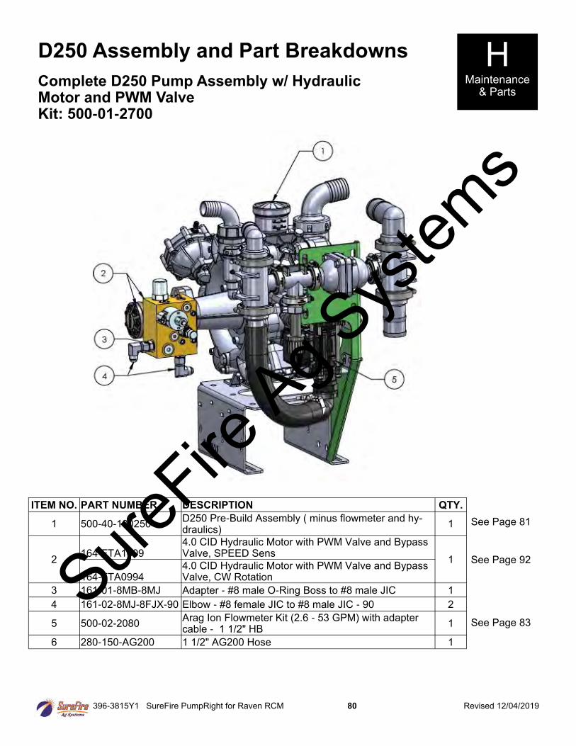
396-3815Y1 SureFire PumpRight for Raven RCM 80 Revised 12/04/2019
D250 Assembly and Part Breakdowns H Maintenance
& Parts Complete D250 Pump Assembly w/ Hydraulic Motor and PWM Valve Kit: 500-01-2700
See Page 81
See Page 92
See Page 83
ITEM NO. PART NUMBER DESCRIPTION QTY.
1 500-40-100250 D250 Pre-Build Assembly ( minus flowmeter and hy-draulics)
1
2 164-FTA1609
4.0 CID Hydraulic Motor with PWM Valve and Bypass Valve, SPEED Sens
1
164-FTA0994 4.0 CID Hydraulic Motor with PWM Valve and Bypass Valve, CW Rotation
3 161-01-8MB-8MJ Adapter - #8 male O-Ring Boss to #8 male JIC 1
4 161-02-8MJ-8FJX-90 Elbow - #8 female JIC to #8 male JIC - 90 2
5 500-02-2080 Arag Ion Flowmeter Kit (2.6 - 53 GPM) with adapter cable - 1 1/2" HB
1
6 280-150-AG200 1 1/2" AG200 Hose 1
SureFire
Ag Sys
tems
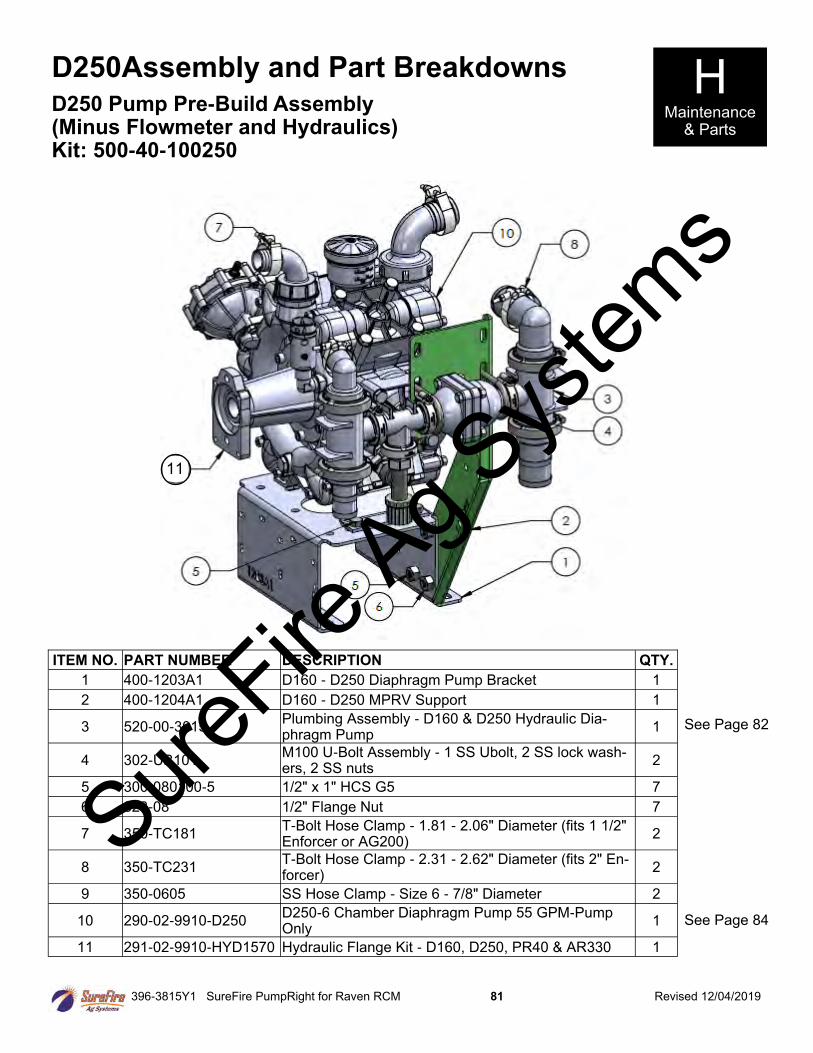
396-3815Y1 SureFire PumpRight for Raven RCM 81 Revised 12/04/2019
D250Assembly and Part Breakdowns H Maintenance
& Parts
D250 Pump Pre-Build Assembly (Minus Flowmeter and Hydraulics) Kit: 500-40-100250
See Page 82
ITEM NO. PART NUMBER DESCRIPTION QTY.
1 400-1203A1 D160 - D250 Diaphragm Pump Bracket 1
2 400-1204A1 D160 - D250 MPRV Support 1
3 520-00-3015 Plumbing Assembly - D160 & D250 Hydraulic Dia-phragm Pump
1
4 302-UB101 M100 U-Bolt Assembly - 1 SS Ubolt, 2 SS lock wash-ers, 2 SS nuts
2
5 300-080100-5 1/2" x 1" HCS G5 7
6 323-08 1/2" Flange Nut 7
7 350-TC181 T-Bolt Hose Clamp - 1.81 - 2.06" Diameter (fits 1 1/2" Enforcer or AG200)
2
8 350-TC231 T-Bolt Hose Clamp - 2.31 - 2.62" Diameter (fits 2" En-forcer)
2
9 350-0605 SS Hose Clamp - Size 6 - 7/8" Diameter 2
10 290-02-9910-D250 D250-6 Chamber Diaphragm Pump 55 GPM-Pump Only
1
11 291-02-9910-HYD1570 Hydraulic Flange Kit - D160, D250, PR40 & AR330 1
11
See Page 84
SureFire
Ag Sys
tems

396-3815Y1 SureFire PumpRight for Raven RCM 82 Revised 12/04/2019
D250 Assembly and Part Breakdowns H Maintenance
& Parts
D250 & PR40 Pump Plumbing Assembly Kit: 520-00-3015
ITEM NO. PART NUMBER DESCRIPTION QTY.
1 102-MPRV100-100 Pressure Relief Valve - 100 PSI 1
2 105-200150BRB90 2" Manifold Flng 1-1/2 Barb 90 1
3 105-200150BRB 2" Manifold X 1-1/2" Barb 1
4 105-100TEE 1" Manifold Tee 1
5 105-100075FPT 1" Manifold x 3/4" FPT 1
6 102-23520-3-4 3/4" Throttling Valve with out spring - 150 PSI 1
7 105-200100TEE038 2"Std Port x 1" Flanged Tee 2
8 101-038050 3/8" MPT x 1/2" HB 1
9 101-075050 3/4" MPT x 1/2" HB 1
10 105-200BRB90 2" Manifold x 2" HB - 90 Degree 1
11 105-200BRB 2" Manifold x 2" HB 1
12 113-06-025038 QC to MPT - 1/4" QC x 3/8" MPT 1
13 113-05-025 Plug - 1/4" QC 1
14 105-100G 1" EPDM Manifold Gasket 4
15 105-150G 1 1/2" EPDM Gasket 4
16 105-FC100 1" Manifold Clamp 4
17 105-FC200 2" Manifold Clamp 4
SureFire
Ag Sys
tems
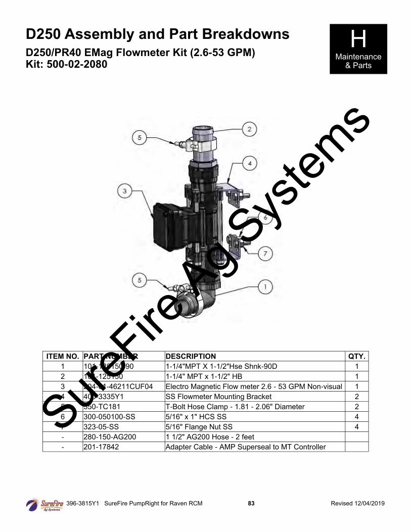
396-3815Y1 SureFire PumpRight for Raven RCM 83 Revised 12/04/2019
D250 Assembly and Part Breakdowns H Maintenance
& Parts
D250/PR40 EMag Flowmeter Kit (2.6-53 GPM) Kit: 500-02-2080
ITEM NO. PART NUMBER DESCRIPTION QTY.
1 101-125150-90 1-1/4"MPT X 1-1/2"Hse Shnk-90D 1
2 101-125150 1-1/4" MPT x 1-1/2" HB 1
3 204-01-46211CUF04 Electro Magnetic Flow meter 2.6 - 53 GPM Non-visual 1
4 400-3335Y1 SS Flowmeter Mounting Bracket 2
5 350-TC181 T-Bolt Hose Clamp - 1.81 - 2.06" Diameter 2
6 300-050100-SS 5/16" x 1" HCS SS 4
7 323-05-SS 5/16" Flange Nut SS 4
- 280-150-AG200 1 1/2" AG200 Hose - 2 feet
- 201-17842 Adapter Cable - AMP Superseal to MT Controller
SureFire
Ag Sys
tems
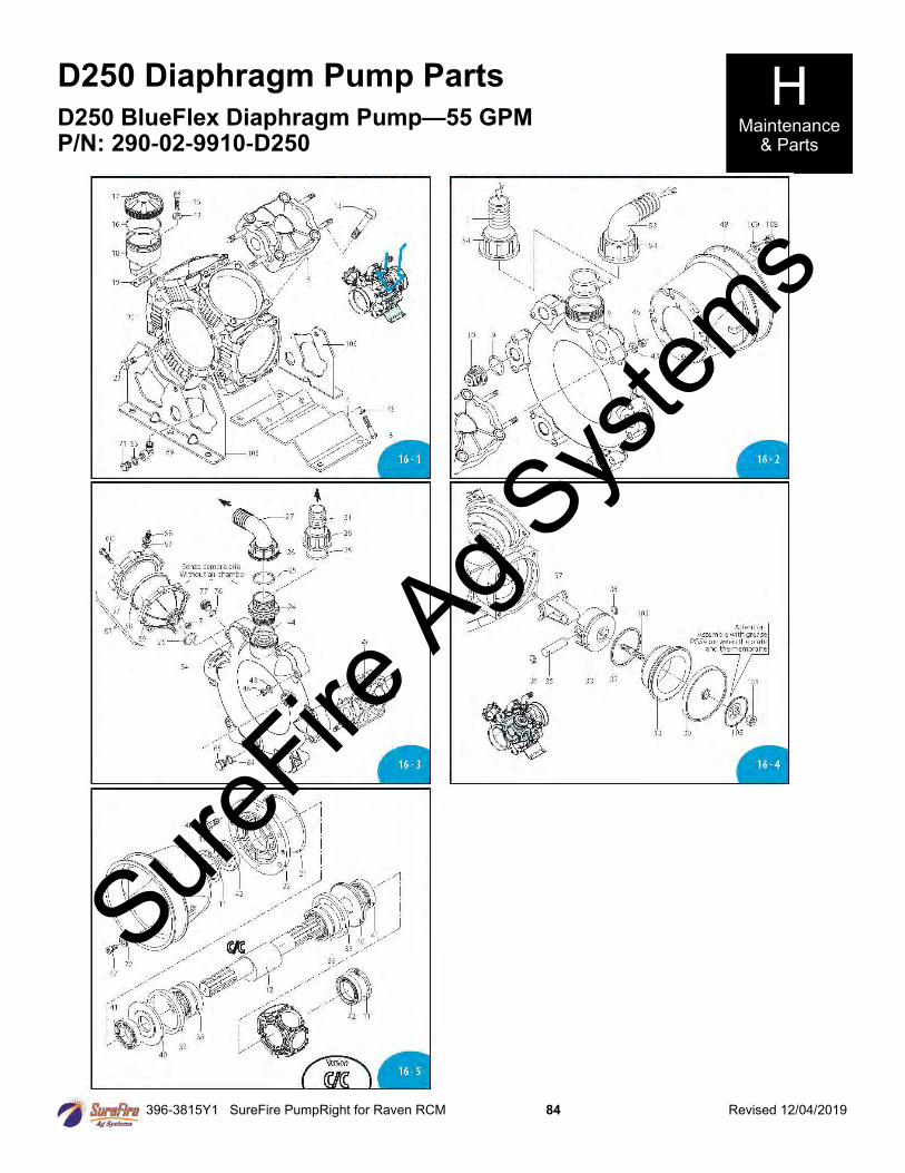
396-3815Y1 SureFire PumpRight for Raven RCM 84 Revised 12/04/2019
D250 Diaphragm Pump Parts H Maintenance
& Parts
D250 BlueFlex Diaphragm Pump—55 GPM P/N: 290-02-9910-D250
SureFire
Ag Sys
tems
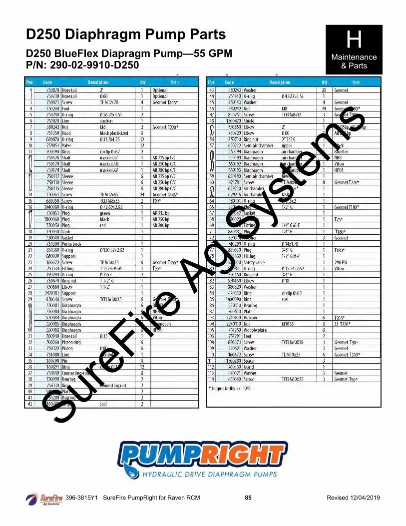
396-3815Y1 SureFire PumpRight for Raven RCM 85 Revised 12/04/2019
D250 Diaphragm Pump Parts H Maintenance
& Parts
D250 BlueFlex Diapragm Pump—55 GPM P/N: 290-02-9910-D250
SureFire
Ag Sys
tems
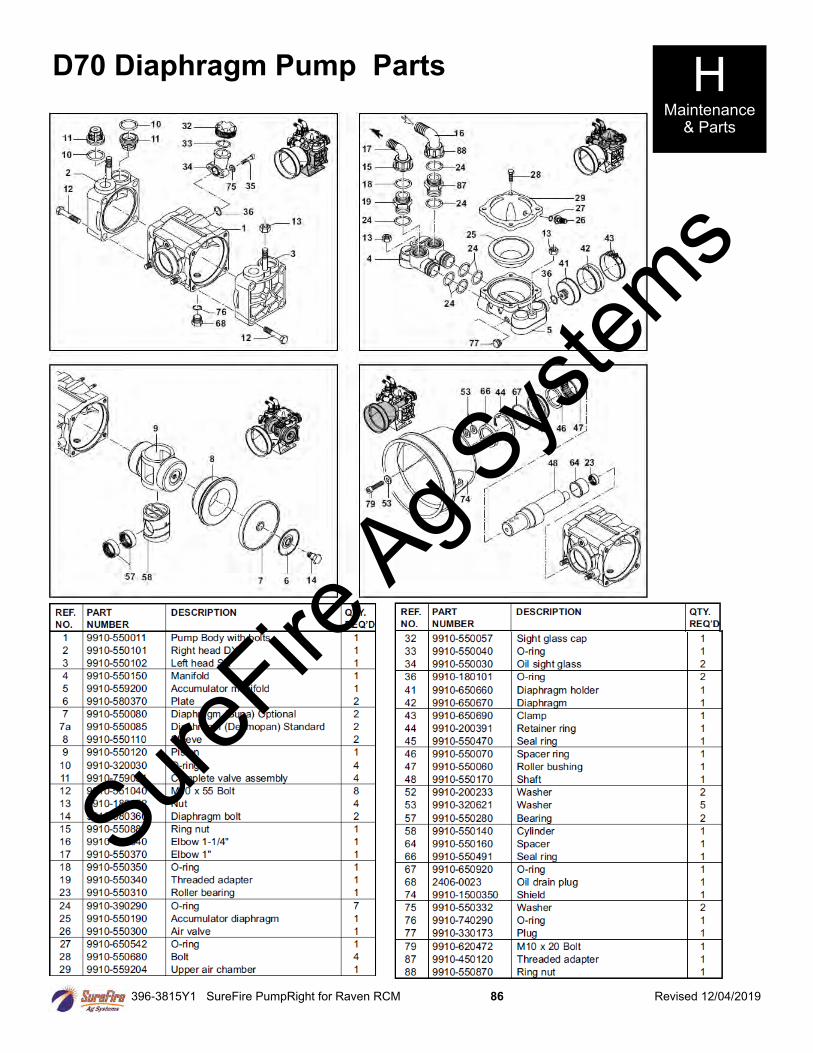
396-3815Y1 SureFire PumpRight for Raven RCM 86 Revised 12/04/2019
D70 Diaphragm Pump Parts H Maintenance
& Parts
SureFire
Ag Sys
tems
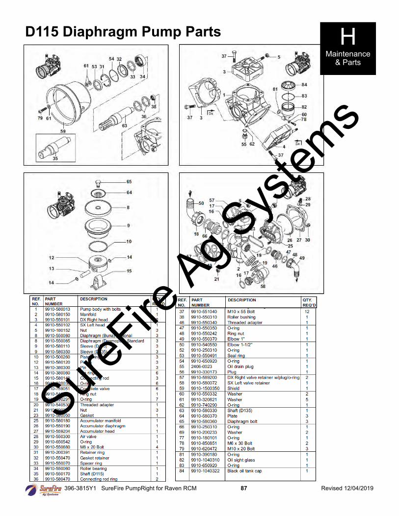
396-3815Y1 SureFire PumpRight for Raven RCM 87 Revised 12/04/2019
D115 Diaphragm Pump Parts H Maintenance
& Parts
SureFire
Ag Sys
tems
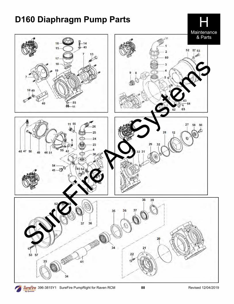
396-3815Y1 SureFire PumpRight for Raven RCM 88 Revised 12/04/2019
D160 Diaphragm Pump Parts H Maintenance
& Parts
SureFire
Ag Sys
tems
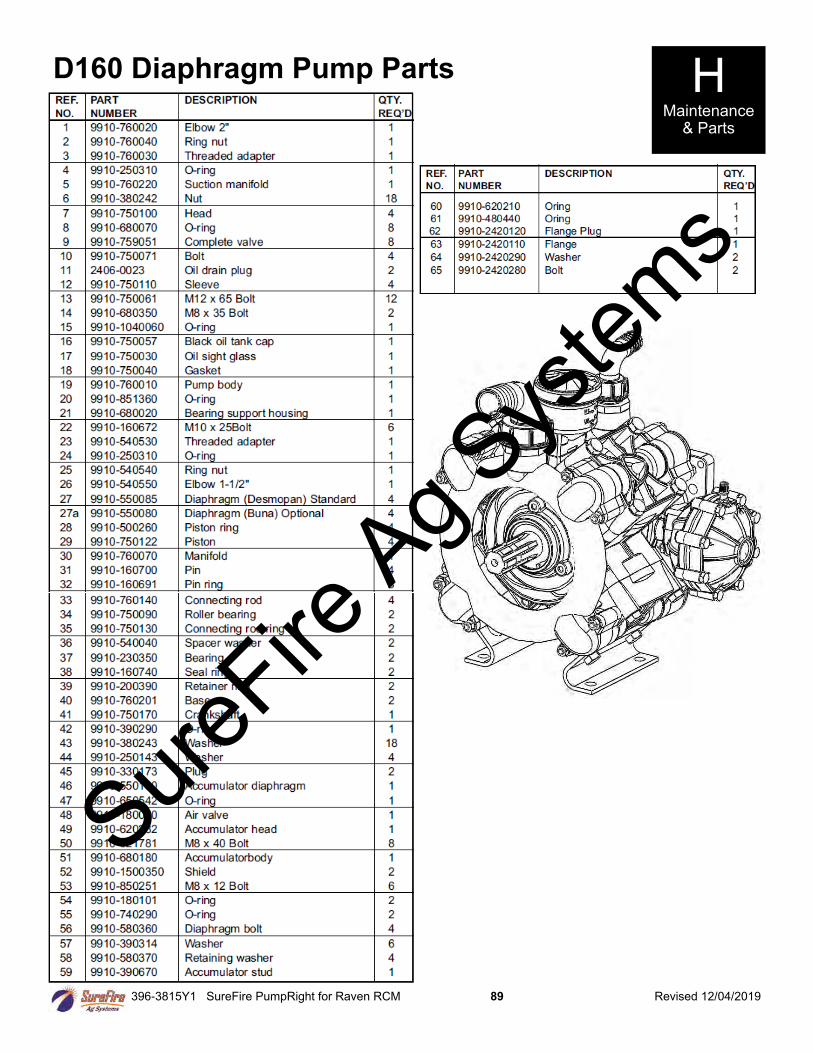
396-3815Y1 SureFire PumpRight for Raven RCM 89 Revised 12/04/2019
D160 Diaphragm Pump Parts H Maintenance
& Parts
SureFire
Ag Sys
tems
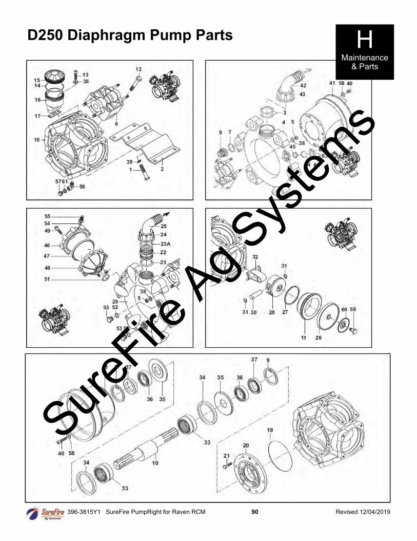
396-3815Y1 SureFire PumpRight for Raven RCM 90 Revised 12/04/2019
D250 Diaphragm Pump Parts H Maintenance
& Parts
SureFire
Ag Sys
tems
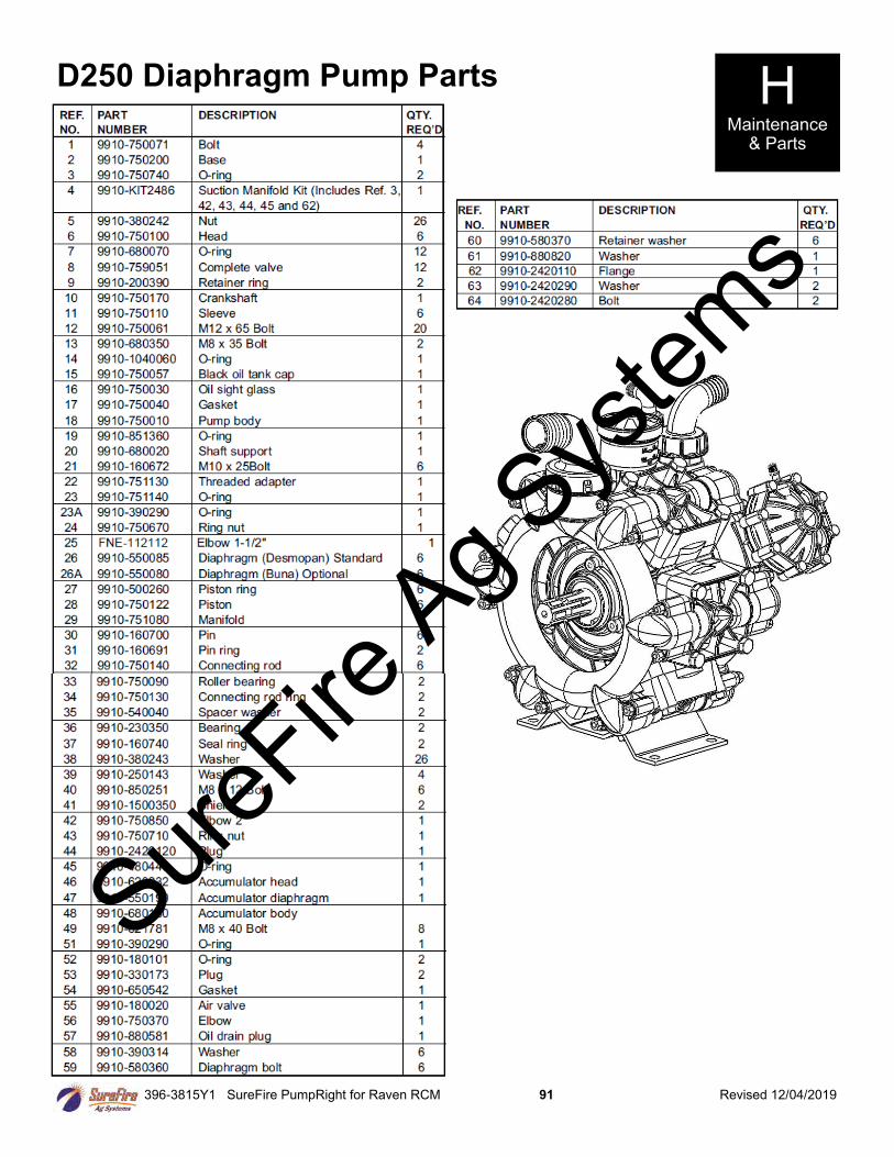
396-3815Y1 SureFire PumpRight for Raven RCM 91 Revised 12/04/2019
D250 Diaphragm Pump Parts H Maintenance
& Parts
SureFire
Ag Sys
tems
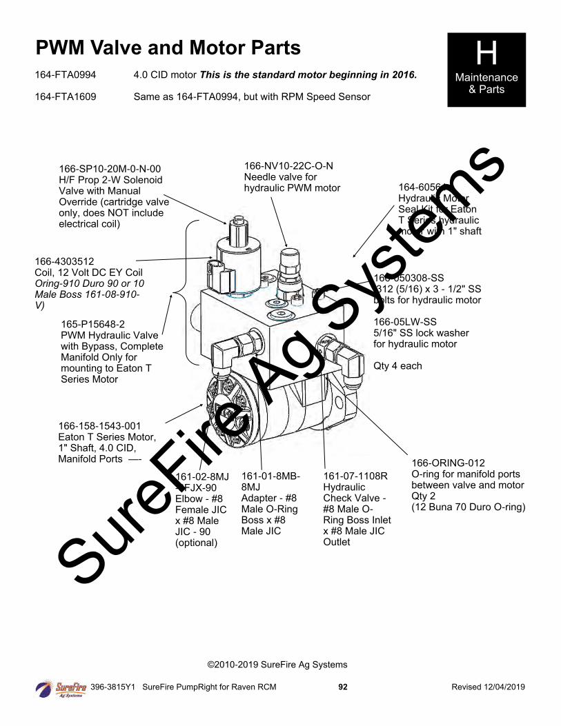
396-3815Y1 SureFire PumpRight for Raven RCM 92 Revised 12/04/2019
PWM Valve and Motor Parts H Maintenance
& Parts
164-60564 Hydraulic Motor Seal Kit for Eaton T Series hydraulic motor with 1" shaft
166-ORING-012 O-ring for manifold ports between valve and motor Qty 2 (12 Buna 70 Duro O-ring)
166-NV10-22C-O-N Needle valve for hydraulic PWM motor
166-158-1543-001 Eaton T Series Motor, 1" Shaft, 4.0 CID, Manifold Ports —-
166-4303512 Coil, 12 Volt DC EY Coil Oring-910 Duro 90 or 10 Male Boss 161-08-910-V)
166-SP10-20M-0-N-00 H/F Prop 2-W Solenoid Valve with Manual Override (cartridge valve only, does NOT include electrical coil)
166-050308-SS .312 (5/16) x 3 - 1/2" SS bolts for hydraulic motor 166-05LW-SS 5/16" SS lock washer for hydraulic motor Qty 4 each
161-01-8MB-8MJ Adapter - #8 Male O-Ring Boss x #8 Male JIC
161-07-1108R Hydraulic Check Valve - #8 Male O-Ring Boss Inlet x #8 Male JIC Outlet
161-02-8MJ-8FJX-90 Elbow - #8 Female JIC x #8 Male JIC - 90 (optional)
164-FTA0994 4.0 CID motor This is the standard motor beginning in 2016. 164-FTA1609 Same as 164-FTA0994, but with RPM Speed Sensor
165-P15648-2 PWM Hydraulic Valve with Bypass, Complete Manifold Only for mounting to Eaton T Series Motor
©2010-2019 SureFire Ag Systems
SureFire
Ag Sys
tems