396 3053Y1 - SureFire Ag · 2016. 5. 23. · 396-3053Y1 SureFire Tower 100 for NutriSphere®-N NH3...
44
396-3053Y1 SureFire Tower 100 for NutriSphere®-N NH3 for Pro 700 Revised 04/13/2016 Tower 100 Electric Pump System for NutriSphere-N® NH3 396-3053Y1 AFS Pro 700 AccuControl SureFire Ag Systems
Transcript of 396 3053Y1 - SureFire Ag · 2016. 5. 23. · 396-3053Y1 SureFire Tower 100 for NutriSphere®-N NH3...
396-3053Y1 SureFire Tower 100 for NutriSphere®-N NH3 for Pro 700 Revised 04/13/2016
Tower 100 Electric Pump System for NutriSphere-N® NH3
396-3053Y1
AFS Pro 700
AccuControl
SureFire
Ag Sys
tems
SureFire
Ag Sys
tems
396-3053Y1 SureFire Tower 100 for NutriSphere®-N NH3 for Pro 700 Revised 04/13/2016
Table Of Contents
A Introduction
Introduction Read Me First ......................................................................................... 2 Basic Steps to Install your System ......................................................... 3 System Overview Drawing ..................................................................... 4
B Components
Liquid
Components - Liquid Flowmeter, Electric Shutoff and Section Valves ..................................... 5,6 Pressure Sensor, Pump Priming and Air Bleed Valve ............................ 7 Flow Indicators and Manifolds ................................................................ 8,10 Dual Check Valve Systems, Metering Tube, Row Distribution ............... 10-11 Plumbing Setup, Shank and Knife Points ............................................... 11-12 Toolbox (Spare Parts) ............................................................................ 13
D Components
Wiring & Elec.
Components - Wiring & Electrical Connecting to Pro 700 AccuControl with Field-IQ Module ...................... 14-15 System Layout ........................................................................................ 16 PWM EPD .............................................................................................. 17 Wiring Harness Drawings ....................................................................... 18-20
E Installation Overview
Installation Overview Harness Connections, ZIP Valve Mounting ............................................ 21 Tower 100 Plumbing Overview and Valve Operation, Recirculation ...... 22 Tower 100 Plumbing Detail .................................................................... 23 Tower 100 Tank Cradle and Mounting Brackets .................................... 24
F Setup &
Operation
Controller Setup & Operation Pro 700 Display General Setup ............................................................... 25-26 AccuControl Configuration ...................................................................... 27-28 Create a Layout, Valve Calibration ......................................................... 29 Product Setup, Layer Assignment, Work Condition > Control ................. 30 Setup Screenshots—Run Screen, Valve Cal, Liquid Drive Setup, more . 31
H Maintenance
& Parts
Maintenance & Parts Winterization and Maintenance Recommendations ............................... 41 Pre-season Service ................................................................................ 41
G Trouble- Shooting
Troubleshooting FAQs, Operating Tips, Troubleshooting Tips .......................................... 32-34 Row Flow and Pump Output Chart ......................................................... 34 Pump Will Not Run, Flowmeter Not Reading .......................................... 35-36 Important Setup and Troubleshooting Procedures ........................... 37 Troubleshooting Pump, PWM, and Section Valves ............................... 38-39 Application Rate fluctuates, Slow Getting to Target Rate ....................... 40
©2015-2016 SureFire Ag Systems
SureFire
Ag Sys
tems
396-3053Y1 SureFire Tower 100 for NutriSphere®-N NH3 for Pro 700 2 Revised 04/13/2016
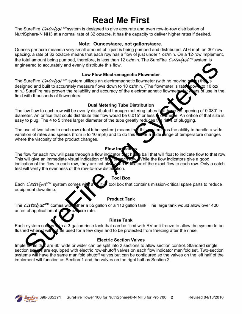
Read Me First The SureFire Catalyst™ system is designed to give accurate and even row-to-row distribution of
NutriSphere-N NH3 at a normal rate of 32 oz/acre. It has the capacity to deliver higher rates if desired.
Note: Ounces/acre, not gallons/acre.
Ounces per acre means a very small amount of liquid is being pumped and distributed. At 6 mph on 30” row spacing, a rate of 32 oz/acre means that each row has a flow of just under 1 oz/min. On a 12-row implement,
the total amount being pumped, therefore, is less than 12 oz/min. The SureFire Catalyst™ system is
engineered to accurately and evenly distribute this flow.
Low Flow Electromagnetic Flowmeter
The SureFire Catalyst™ system utilizes an electromagnetic flowmeter (with no moving parts) that is
designed and built to accurately measure flows down to 10 oz/min. (The flowmeter is rated down to 10 oz/min.) SureFire has proven the reliability and accuracy of the electromagnetic flowmeter by years of use in the field with thousands of flowmeters.
Dual Metering Tube Distribution
The low flow to each row will be evenly distributed through metering tubes that have an opening of 0.080” in diameter. An orifice that could distribute this flow would be 0.015” or less in diameter. An orifice of that size is easy to plug. The 4 to 5 times larger diameter of the tube greatly reduces the risks of plugging. The use of two tubes to each row (dual tube system) means that this system has the ability to handle a wide variation of rates and speeds (from 5 to 10 mph) and to do this under a wide range of temperature changes where the viscosity of the product changes.
Flow Indicators
The flow for each row will pass through a flow indicator that has a ball that will float to indicate flow to that row. This will give an immediate visual indication of flow to each row. While the flow indicators give a good indication of the flow to each row, they are not always an indicator of the exact flow to each row. Only a catch test will verify the evenness of the row-to-row distribution.
Tool Box
Each Catalyst™ system comes with a built-in tool box that contains mission-critical spare parts to reduce
equipment downtime.
Product Tank
The Catalyst™ comes with either a 55 gallon or a 110 gallon tank. The large tank would allow over 400
acres of application at the 32 oz/acre rate.
Rinse Tank
Each system comes with a 3-gallon rinse tank that can be filled with RV anti-freeze to allow the system to be flushed when it will not be used for a few days and to be protected from freezing after the rinse.
Electric Section Valves
Implements that are 60’ wide or wider can be split into 2 sections to allow section control. Standard single section setups are equipped with electric row-shutoff valves on each flow indicator manifold set. Two-section systems will have the same manifold shutoff valves but can be configured so the valves on the left half of the implement will function as Section 1 and the valves on the right half as Section 2.
SureFire
Ag Sys
tems
396-3053Y1 SureFire Tower 100 for NutriSphere®-N NH3 for Pro 700 3 Revised 04/13/2016
Getting Started
This manual contains the information for the SureFire Tower 100 system for NutriSphere-N NH3 that is being introduced in June, 2015.
Changes to components or configuration settings may be made to improve the operation of the system.
Go to the tab in Section F for the instructions on setting up your display.
You have purchased a SureFire NutriSphere NH3 application system for your equipment. This system can be controlled by:
John Deere Rate Controller
Ag Leader Liquid Product Control Module
Trimble Field-IQ Rate and Section Control Module
Case IH Pro 700 with AccuControl
SureFire Commander II controller
Note: SureFire Ag Systems also has the SureFire Torpedo system, a complete anhydrous ammonia application system. See www.surefireag.com for more information.
A Introduction
Basic Installation Steps
1. Have your control module and display in the cab connected and set up by the dealer for your display and controller. To apply anhydrous ammonia and NutriSphere-N NH3 you will need 2 Field-IQ modules, one for each product.
2. Open the packages and familiarize yourself with the components. See the System Overview Examples on the following pages to see the big picture of how SureFire Fertilizer Systems are installed. Refer to manual sections B & D for component information.
3. Mount the Tower and tank on your equipment.
4. Install the plumbing kit including flow indicator columns, electric ZIP valves, and metering tube plumbing to each row unit delivery point. See sections B & E for information on these components.
5. Attach harnesses as shown in Section D.
6. Setup Controller for SureFire fertilizer system as shown in Section F.
7. Fill system with water, conduct initial operation and tests per Section F.
8. Winterize system with RV Antifreeze if freezing temperatures are expected.
General Information
SureFire
Ag Sys
tems
396-3053Y1 SureFire Tower 100 for NutriSphere®-N NH3 for Pro 700 4 Revised 04/13/2016
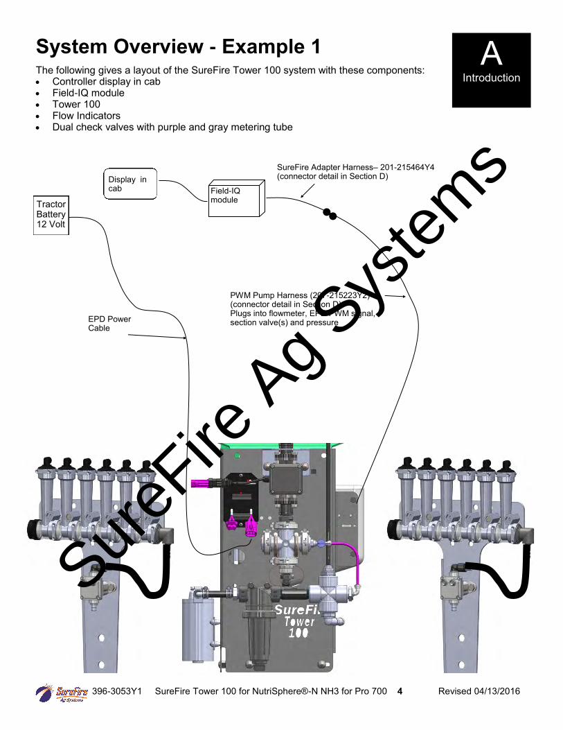
System Overview - Example 1
The following gives a layout of the SureFire Tower 100 system with these components: Controller display in cab Field-IQ module Tower 100 Flow Indicators Dual check valves with purple and gray metering tube
A Introduction
Tractor Battery 12 Volt
SureFire Adapter Harness– 201-215464Y4(connector detail in Section D)
PWM Pump Harness (207-215223Y2) (connector detail in Section D) Plugs into flowmeter, EPD PWM signal, section valve(s) and pressure
Field-IQ module
Display in cab
EPD Power Cable
SureFire
Ag Sys
tems
396-3053Y1 SureFire Tower 100 for NutriSphere®-N NH3 for Pro 700 5 Revised 04/13/2016
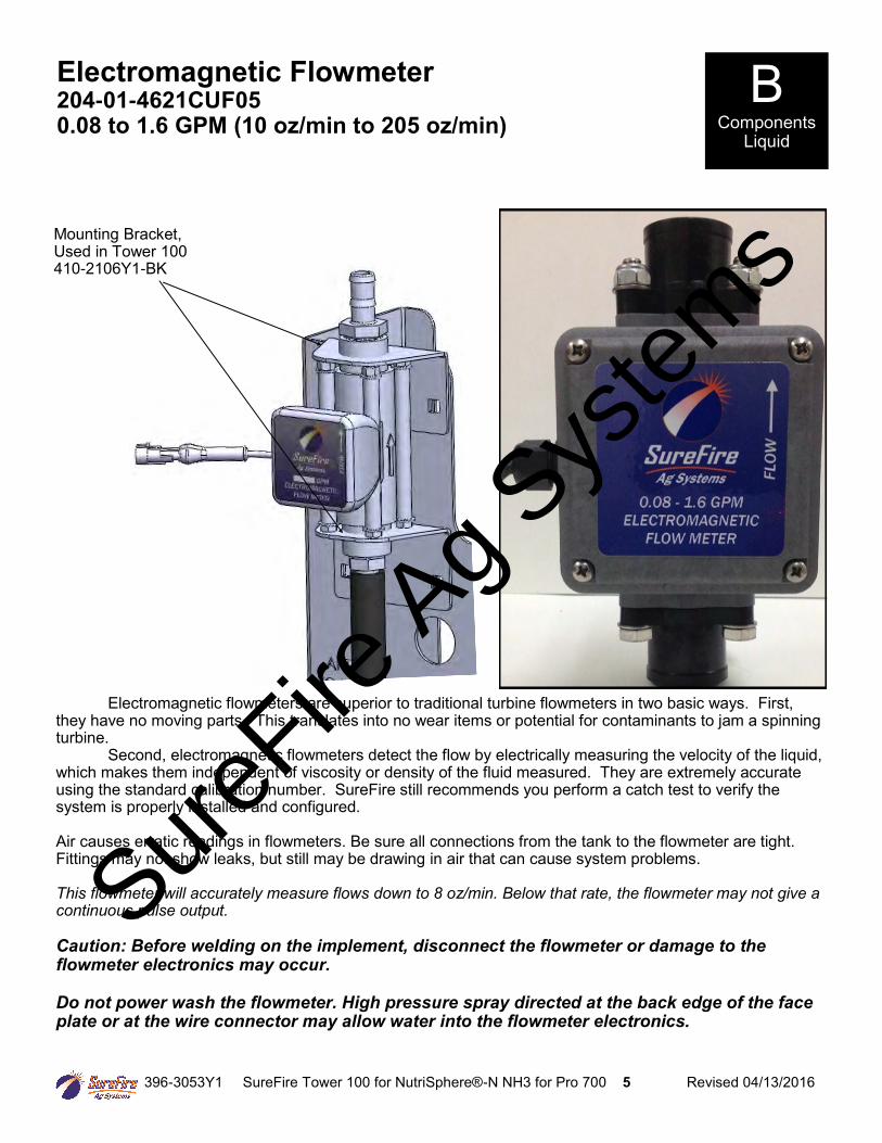
Electromagnetic Flowmeter 204-01-4621CUF05 0.08 to 1.6 GPM (10 oz/min to 205 oz/min)
B Components
Liquid
Mounting Bracket, Used in Tower 100 410-2106Y1-BK
Electromagnetic flowmeters are superior to traditional turbine flowmeters in two basic ways. First, they have no moving parts. This translates into no wear items or potential for contaminants to jam a spinning turbine. Second, electromagnetic flowmeters detect the flow by electrically measuring the velocity of the liquid, which makes them independent of viscosity or density of the fluid measured. They are extremely accurate using the standard calibration number. SureFire still recommends you perform a catch test to verify the system is properly installed and configured. Air causes erratic readings in flowmeters. Be sure all connections from the tank to the flowmeter are tight. Fittings may not show leaks, but still may be drawing in air that can cause system problems. This flowmeter will accurately measure flows down to 8 oz/min. Below that rate, the flowmeter may not give a continuous pulse output. Caution: Before welding on the implement, disconnect the flowmeter or damage to the flowmeter electronics may occur. Do not power wash the flowmeter. High pressure spray directed at the back edge of the face plate or at the wire connector may allow water into the flowmeter electronics.
SureFire
Ag Sys
tems
396-3053Y1 SureFire Tower 100 for NutriSphere®-N NH3 for Pro 700 6 Revised 04/13/2016
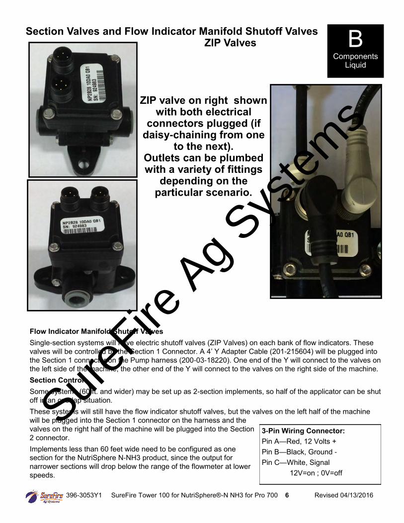
Section Valves and Flow Indicator Manifold Shutoff Valves ZIP Valves
ZIP valve on right shown with both electrical
connectors plugged (if daisy-chaining from one
to the next). Outlets can be plumbed with a variety of fittings
depending on the particular scenario.
Flow Indicator Manifold Shutoff Valves
Single-section systems will have electric shutoff valves (ZIP Valves) on each bank of flow indicators. These
valves will be controlled by the Section 1 Connector. A 4’ Y Adapter Cable (201-215604) will be plugged into
the Section 1 connector on the Pump harness (200-03-18220). One end of the Y will connect to the valves on
the left side of the machine, the other end of the Y will connect to the valves on the right side of the machine.
Section Control Some systems (60 ft. and wider) may be set up as 2-section implements, so half of the applicator can be shut
off in an overlap situation. These systems will still have the flow indicator shutoff valves, but the valves on the left half of the machine
will be plugged into the Section 1 connector on the harness and the
valves on the right half of the machine will be plugged into the Section
2 connector. Implements less than 60 feet wide need to be configured as one
section for the NutriSphere N-NH3 product, since the output for
narrower sections will drop below the range of the flowmeter at lower
speeds.
3-Pin Wiring Connector:
Pin A—Red, 12 Volts + Pin B—Black, Ground - Pin C—White, Signal 12V=on ; 0V=off
B Components
Liquid
SureFire
Ag Sys
tems
396-3053Y1 SureFire Tower 100 for NutriSphere®-N NH3 for Pro 700 7 Revised 04/13/2016
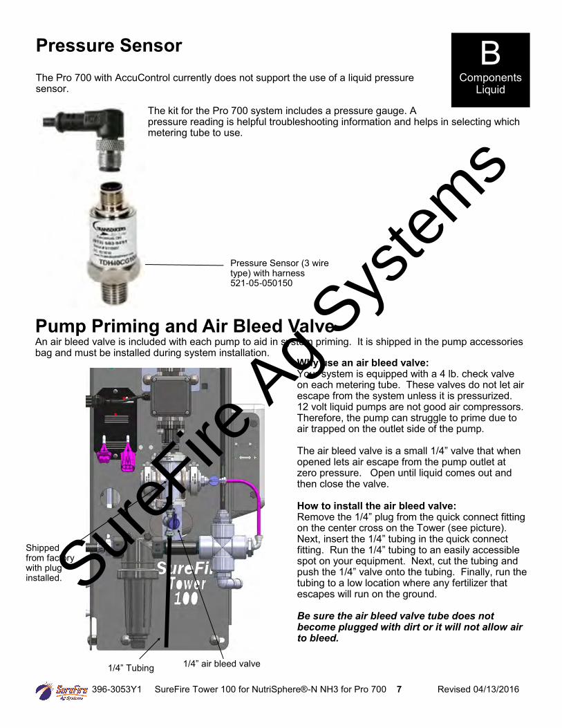
The Pro 700 with AccuControl currently does not support the use of a liquid pressure sensor.
The kit for the Pro 700 system includes a pressure gauge. A pressure reading is helpful troubleshooting information and helps in selecting which metering tube to use.
Pressure Sensor B Components
Liquid
Pressure Sensor (3 wire type) with harness 521-05-050150
Pump Priming and Air Bleed Valve An air bleed valve is included with each pump to aid in system priming. It is shipped in the pump accessories bag and must be installed during system installation.
Why use an air bleed valve: Your system is equipped with a 4 lb. check valve on each metering tube. These valves do not let air escape from the system unless it is pressurized. 12 volt liquid pumps are not good air compressors. Therefore, the pump can struggle to prime due to air trapped on the outlet side of the pump. The air bleed valve is a small 1/4” valve that when opened lets air escape from the pump outlet at zero pressure. Open until liquid comes out and then close the valve. How to install the air bleed valve: Remove the 1/4” plug from the quick connect fitting on the center cross on the Tower (see picture). Next, insert the 1/4” tubing in the quick connect fitting. Run the 1/4” tubing to an easily accessible spot on your equipment. Next, cut the tubing and push the 1/4” valve onto the tubing. Finally, run the tubing to a low location where any fertilizer that escapes will run on the ground. Be sure the air bleed valve tube does not become plugged with dirt or it will not allow air to bleed.
1/4” Tubing 1/4” air bleed valve
Shipped from factory with plug installed. Sure
Fire Ag S
ystem
s
396-3053Y1 SureFire Tower 100 for NutriSphere®-N NH3 for Pro 700 8 Revised 04/13/2016
B Components
Liquid
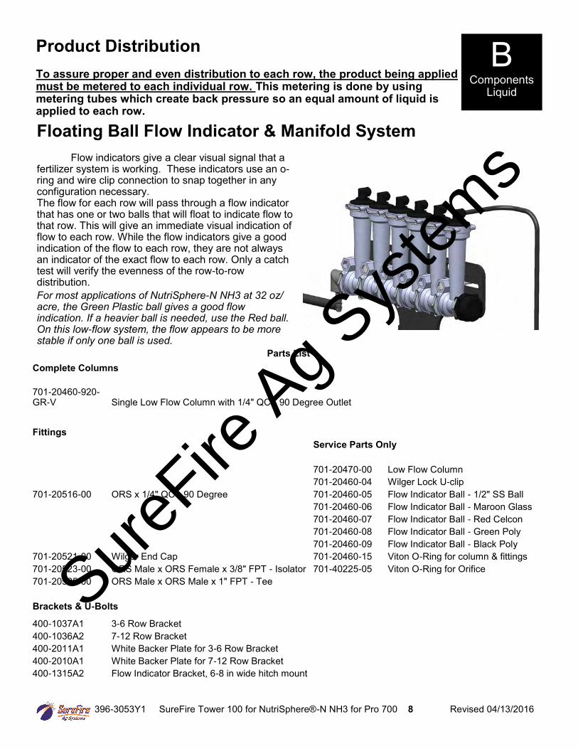
Floating Ball Flow Indicator & Manifold System
Flow indicators give a clear visual signal that a fertilizer system is working. These indicators use an o-ring and wire clip connection to snap together in any configuration necessary. The flow for each row will pass through a flow indicator that has one or two balls that will float to indicate flow to that row. This will give an immediate visual indication of flow to each row. While the flow indicators give a good indication of the flow to each row, they are not always an indicator of the exact flow to each row. Only a catch test will verify the evenness of the row-to-row distribution. For most applications of NutriSphere-N NH3 at 32 oz/acre, the Green Plastic ball gives a good flow indication. If a heavier ball is needed, use the Red ball. On this low-flow system, the flow appears to be more stable if only one ball is used.
Parts List
Complete Columns
701-20460-920-GR-V Single Low Flow Column with 1/4" QC - 90 Degree Outlet
Fittings
Service Parts Only
701-20470-00 Low Flow Column 701-20460-04 Wilger Lock U-clip 701-20516-00 ORS x 1/4" QC - 90 Degree 701-20460-05 Flow Indicator Ball - 1/2" SS Ball 701-20460-06 Flow Indicator Ball - Maroon Glass 701-20460-07 Flow Indicator Ball - Red Celcon 701-20460-08 Flow Indicator Ball - Green Poly 701-20460-09 Flow Indicator Ball - Black Poly 701-20521-00 Wilger End Cap 701-20460-15 Viton O-Ring for column & fittings 701-20523-00 ORS Male x ORS Female x 3/8" FPT - Isolator 701-40225-05 Viton O-Ring for Orifice 701-20525-00 ORS Male x ORS Male x 1" FPT - Tee
Brackets & U-Bolts
400-1037A1 3-6 Row Bracket 400-1036A2 7-12 Row Bracket
400-2011A1 White Backer Plate for 3-6 Row Bracket 400-2010A1 White Backer Plate for 7-12 Row Bracket 400-1315A2 Flow Indicator Bracket, 6-8 in wide hitch mount
Product Distribution To assure proper and even distribution to each row, the product being applied must be metered to each individual row. This metering is done by using metering tubes which create back pressure so an equal amount of liquid is applied to each row.
SureFire
Ag Sys
tems
396-3053Y1 SureFire Tower 100 for NutriSphere®-N NH3 for Pro 700 9 Revised 04/13/2016
B Components
Liquid
400-1037A1 3-6 Row Bracket
400-2011A1 6 Row White Visi-bility Backer Plate
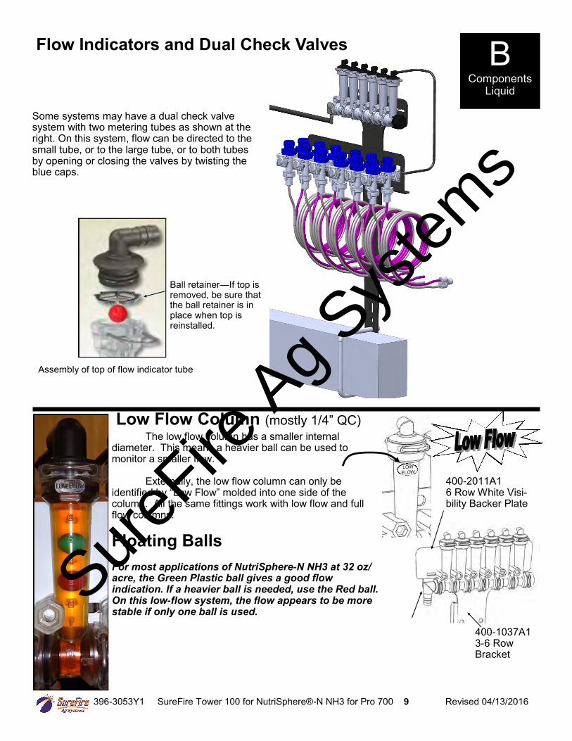
The low flow column has a smaller internal diameter. This means a heavier ball can be used to monitor a smaller flow. Externally, the low flow column can only be identified by “Low Flow” molded into one side of the column. All the same fittings work with low flow and full flow columns. Floating Balls For most applications of NutriSphere-N NH3 at 32 oz/acre, the Green Plastic ball gives a good flow indication. If a heavier ball is needed, use the Red ball. On this low-flow system, the flow appears to be more stable if only one ball is used.
Low Flow Column (mostly 1/4” QC)
Ball retainer—If top is removed, be sure that the ball retainer is in place when top is reinstalled.
Flow Indicators and Dual Check Valves
Assembly of top of flow indicator tube
Some systems may have a dual check valve system with two metering tubes as shown at the right. On this system, flow can be directed to the small tube, or to the large tube, or to both tubes by opening or closing the valves by twisting the blue caps.
SureFire
Ag Sys
tems
396-3053Y1 SureFire Tower 100 for NutriSphere®-N NH3 for Pro 700 10 Revised 04/13/2016
Dual Metering Tube Plumbing Kits with Dual Check Valve
The SureFire Catalyst Tower 100 NutriSphere-N NH3 system comes with a dual metering tube distribution
system. These plumbing kits will contain everything you need to distribute product from the flowmeter outlet down to the ground application device. For most applications of NutriSphere-N NH3 at 32 oz/acre on 30” rows, the purple tube will be the tube that is used. When applying in cold weather and/or at high speeds, it may be necessary to use the blue tube. The system will work at pressures up to 50 PSI, but for prolonged use above 45 PSI, consider switching to a larger tube.
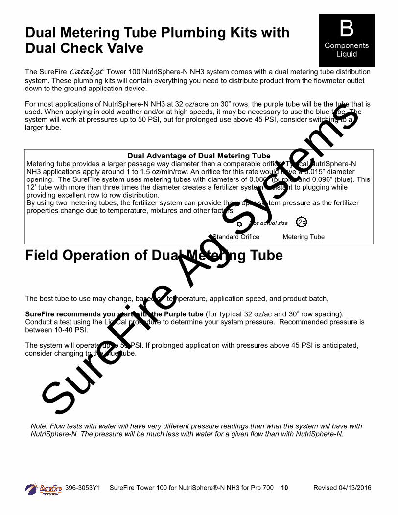
Dual Advantage of Dual Metering Tube Metering tube provides a larger passage way diameter than a comparable orifice. Typical NutriSphere-N NH3 applications apply around 1 to 1.5 oz/min/row. An orifice for this rate would have a 0.015” diameter opening. The SureFire system uses metering tubes with diameters of 0.080” (purple) and 0.096” (blue). This 12’ tube with more than three times the diameter creates a fertilizer system resistant to plugging while providing excellent row to row distribution. By using two metering tubes, the fertilizer system can provide the proper system pressure as the fertilizer properties change due to temperature, mixtures and other factors.
Standard Orifice Metering Tube
2x
Field Operation of Dual Metering Tube
B Components
Liquid
Not actual size
Note: Flow tests with water will have very different pressure readings than what the system will have with NutriSphere-N. The pressure will be much less with water for a given flow than with NutriSphere-N.
The best tube to use may change, based on temperature, application speed, and product batch, SureFire recommends you start with the Purple tube (for typical 32 oz/ac and 30” row spacing). Conduct a test using the Liq Cal procedure to determine your system pressure. Recommended pressure is between 10-40 PSI. The system will operate up to 50 PSI. If prolonged application with pressures above 45 PSI is anticipated, consider changing to the blue tube.
SureFire
Ag Sys
tems
396-3053Y1 SureFire Tower 100 for NutriSphere®-N NH3 for Pro 700 11 Revised 04/13/2016
B Components
Liquid
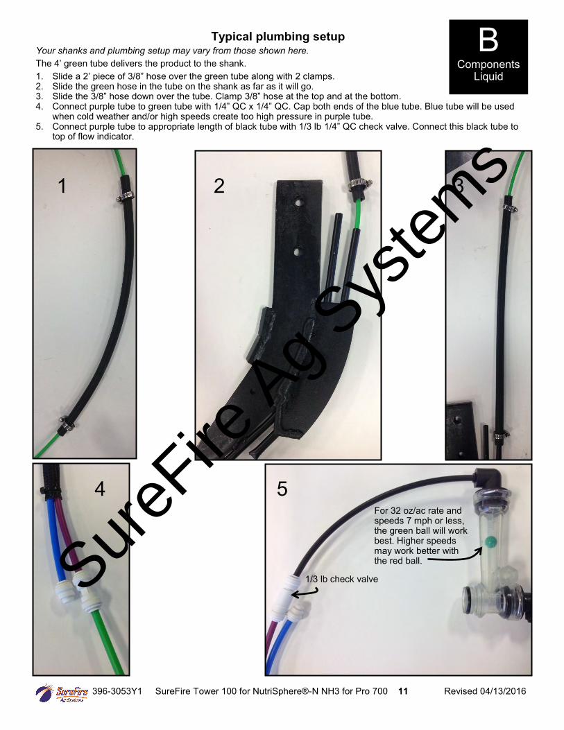
Typical plumbing setup Your shanks and plumbing setup may vary from those shown here.
The 4’ green tube delivers the product to the shank. 1. Slide a 2’ piece of 3/8” hose over the green tube along with 2 clamps. 2. Slide the green hose in the tube on the shank as far as it will go. 3. Slide the 3/8” hose down over the tube. Clamp 3/8” hose at the top and at the bottom. 4. Connect purple tube to green tube with 1/4” QC x 1/4” QC. Cap both ends of the blue tube. Blue tube will be used
when cold weather and/or high speeds create too high pressure in purple tube. 5. Connect purple tube to appropriate length of black tube with 1/3 lb 1/4” QC check valve. Connect this black tube to
top of flow indicator.
1 2 3
4 5 For 32 oz/ac rate and speeds 7 mph or less, the green ball will work best. Higher speeds may work better with the red ball.
1/3 lb check valve SureFire
Ag Sys
tems
396-3053Y1 SureFire Tower 100 for NutriSphere®-N NH3 for Pro 700 12 Revised 04/13/2016
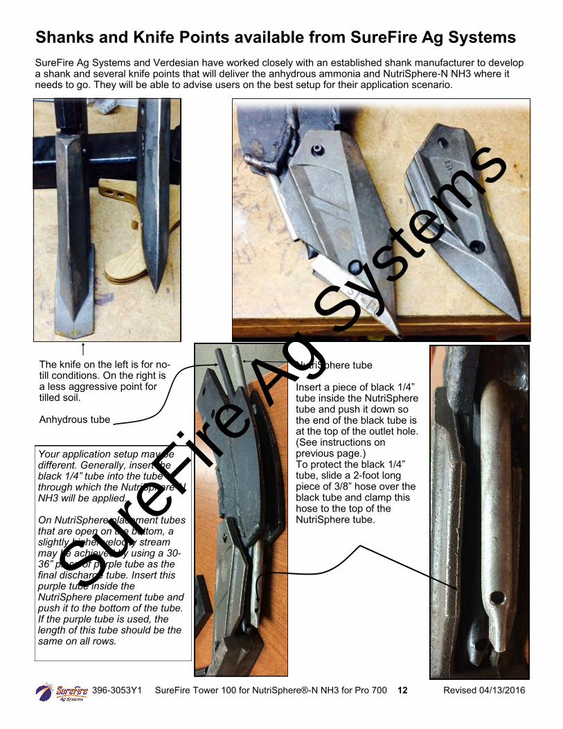
Shanks and Knife Points available from SureFire Ag Systems
SureFire Ag Systems and Verdesian have worked closely with an established shank manufacturer to develop a shank and several knife points that will deliver the anhydrous ammonia and NutriSphere-N NH3 where it needs to go. They will be able to advise users on the best setup for their application scenario.
The knife on the left is for no-till conditions. On the right is a less aggressive point for tilled soil. Anhydrous tube
NutriSphere tube Insert a piece of black 1/4” tube inside the NutriSphere tube and push it down so the end of the black tube is at the top of the outlet hole. (See instructions on previous page.) To protect the black 1/4” tube, slide a 2-foot long piece of 3/8” hose over the black tube and clamp this hose to the top of the NutriSphere tube.
Your application setup may be different. Generally, insert the black 1/4” tube into the tube through which the NutriSphere-N NH3 will be applied. On NutriSphere placement tubes that are open on the bottom, a slightly higher velocity stream may be achieved by using a 30-36” piece of purple tube as the final discharge tube. Insert this purple tube inside the NutriSphere placement tube and push it to the bottom of the tube. If the purple tube is used, the length of this tube should be the same on all rows.
SureFire
Ag Sys
tems

396-3053Y1 SureFire Tower 100 for NutriSphere®-N NH3 for Pro 700 13 Revised 04/13/2016
Toolbox (no tools, just spare parts) A toolbox containing critical items will be included with each system. The toolbox will contain: QTY 1 12 volt electric pump 2 flow indicator columns 10 size 6 hose clamps 1 3/8” HB 90 degree electric pump fitting 1 3/8” HB straight electric pump fitting 2 40 Amp fuses 1 1” Tee Strainer gasket-FKM 2 Clips for electric pump 4 QC 1/4” End Stop White Poly Cap 6 QC to QC—1/4” QC x 1/4” QC 2 Check Valve—1/3 lb—1/4” QC x 1/4” QC
B Components
Liquid
SureFire
Ag Sys
tems
396-3053Y1 SureFire Tower 100 for NutriSphere®-N NH3 for Pro 700 14 Revised 04/13/2016
D Wiring & Elec
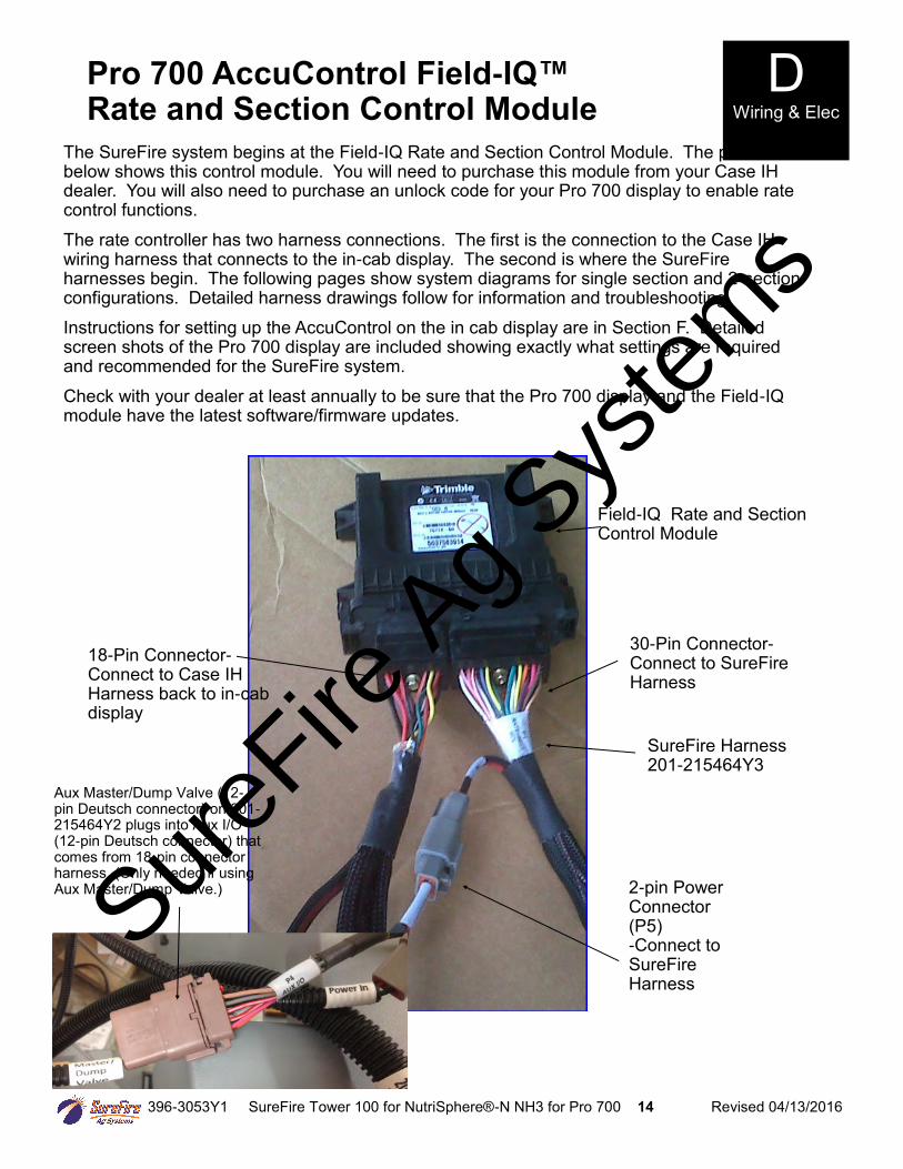
Pro 700 AccuControl Field-IQ™ Rate and Section Control Module
The SureFire system begins at the Field-IQ Rate and Section Control Module. The picture below shows this control module. You will need to purchase this module from your Case IH dealer. You will also need to purchase an unlock code for your Pro 700 display to enable rate control functions.
The rate controller has two harness connections. The first is the connection to the Case IH wiring harness that connects to the in-cab display. The second is where the SureFire harnesses begin. The following pages show system diagrams for single section and 2-section configurations. Detailed harness drawings follow for information and troubleshooting.
Instructions for setting up the AccuControl on the in cab display are in Section F. Detailed screen shots of the Pro 700 display are included showing exactly what settings are required and recommended for the SureFire system. Check with your dealer at least annually to be sure that the Pro 700 display and the Field-IQ module have the latest software/firmware updates.
18-Pin Connector- Connect to Case IH Harness back to in-cab display
Field-IQ Rate and Section Control Module
30-Pin Connector- Connect to SureFire Harness
SureFire Harness
201-215464Y3
2-pin Power Connector (P5)
-Connect to SureFire Harness
Aux Master/Dump Valve (12-pin Deutsch connector) on 201-215464Y2 plugs into Aux I/O (12-pin Deutsch connector) that comes from 18-pin connector harness. (Only needed if using Aux Master/Dump Valve.) Sure
Fire Ag S
ystem
s
396-3053Y1 SureFire Tower 100 for NutriSphere®-N NH3 for Pro 700 15 Revised 04/13/2016
D Wiring & Elec
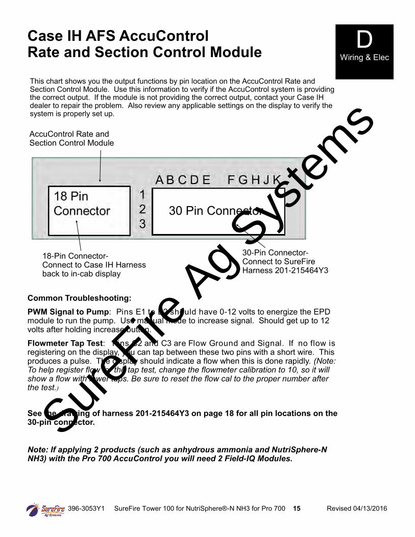
Case IH AFS AccuControl Rate and Section Control Module
This chart shows you the output functions by pin location on the AccuControl Rate and Section Control Module. Use this information to verify if the AccuControl system is providing the correct output. If the module is not providing the correct output, contact your Case IH dealer to repair the problem. Also review any applicable settings on the display to verify the system is properly set up.
AccuControl Rate and Section Control Module
30 Pin Connector
30-Pin Connector- Connect to SureFire Harness 201-215464Y3
18-Pin Connector-
Connect to Case IH Harness back to in-cab display
Common Troubleshooting:
PWM Signal to Pump: Pins E1 to E2 should have 0-12 volts to energize the EPD module to run the pump. Use manual mode to increase signal. Should get up to 12 volts after holding increase button.
Flowmeter Tap Test: Pins C2 and C3 are Flow Ground and Signal. If no flow is registering on the display, you can tap between these two pins with a short wire. This produces a pulse. The display should indicate a flow when this is done rapidly. (Note: To help register flow for the tap test, change the flowmeter calibration to 10, so it will show a flow with fewer taps. Be sure to reset the flow cal to the proper number after the test.)
See the drawing of harness 201-215464Y3 on page 18 for all pin locations on the 30-pin connector.
Note: If applying 2 products (such as anhydrous ammonia and NutriSphere-N NH3) with the Pro 700 AccuControl you will need 2 Field-IQ Modules.
SureFire
Ag Sys
tems
396-3053Y1 SureFire Tower 100 for NutriSphere®-N NH3 for Pro 700 16 Revised 04/13/2016
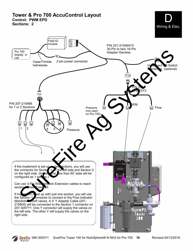
Tower & Pro 700 AccuControl Layout Control: PWM EPD Sections: 2
P/N 207-215223Y2
P/N 201-215464Y3 30-Pin to twin 16-Pin Adapter Harness
If the implement is set up as two sections, you will use the connector for Section 1 on the left side and Section 2 on the right side. (Implements less than 60’ wide will be configured as 1 section.) Can use 3-Pin Weatherpack Extension cables to reach section valves if needed. If implement is set up with just one section, you will use the Section 1 connector to connect to the Flow Indicator Manifold Shutoff valves. A 4’ Y Adapter Cable (201-215604) will be connected to the Section 1 connector on 207-3057Y1. One Y connector will supply the valves on the left side. The other Y will supply the valves on the right side.
PWM Flow Pressure
(not used on Pro 700)
Field IQ module
Pro 700 display in cab
Case/Trimble harnesses
D Wiring & Elec.
Pressure
P/N 207-215466 for 1 or 2 Sections
1 2 4 5 6
Implement Lift Switch Connector (optional)
2-pin power connector
SureFire
Ag Sys
tems
396-3053Y1 SureFire Tower 100 for NutriSphere®-N NH3 for Pro 700 17 Revised 04/13/2016
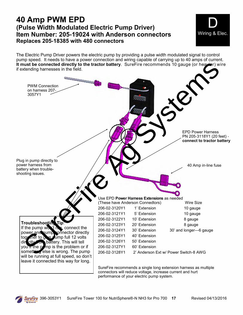
40 Amp PWM EPD (Pulse Width Modulated Electric Pump Driver) Item Number: 205-19024 with Anderson connectors Replaces 205-18385 with 480 connectors
D Wiring & Elec.
40 Amp in-line fuse
EPD Power Harness PN 205-3118Y1 (20 feet) - connect to tractor battery
Plug in pump directly to power harness from battery when trouble-shooting issues.
Use EPD Power Harness Extensions as needed (These have Anderson Connedtors) Wire Size 206-02-3120Y1 1’ Extension 10 gauge 206-02-3121Y1 5’ Extension 10 gauge 206-02-3122Y1 10’ Extension 8 gauge 206-02-3123Y1 20’ Extension 8 gauge 206-02-3124Y1 30’ Extension 30’ and longer—6 gauge
206-02-3125Y1 40’ Extension
206-02-3126Y1 50’ Extension 206-02-3127Y1 60’ Extension 206-02-3128Y1 2’ Anderson Ext w/ Power Switch-8 AWG
SureFire recommends a single long extension harness as multiple connectors will reduce voltage, increase current and hurt performance of your electric pump system.
Troubleshooting Tip: If the pump won’t run, connect the power and pump connector directly together to give pump full 12 volts directly from battery. This will tell you if the pump is the problem or if something else is wrong. The pump will be running at full speed, so don’t leave it connected this way for long.
The Electric Pump Driver powers the electric pump by providing a pulse width modulated signal to control pump speed. It needs to have a power connection and wiring capable of carrying up to 40 amps of current. It must be connected directly to the tractor battery. SureFire recommends 10 gauge (or heavier) wire if extending harnesses in the field.
PWM Connection on harness 207-3057Y1
SureFire
Ag Sys
tems
Project:
Filename:
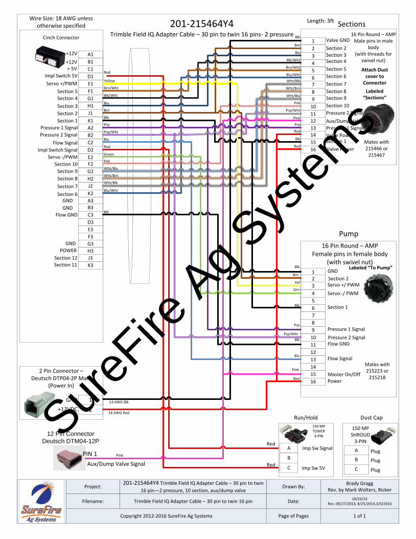
201-215464Y4 Trimble Field IQ Adapter Cable – 30 pin to twin
16 pin—2 pressure, 10 section, aux/dump valve
Trimble Field IQ Adapter Cable – 30 pin to twin 16 pin
Drawn By:
Date:
Brady GraggRev. by Mark Wolters, Ricker
10/23/12Rev. 09/27/2013, 8/25/2014,3/3/2016
Page of Pages 1 of 1Copyright 2012-2016 SureFire Ag Systems
201-215464Y4Trimble Field IQ Adapter Cable – 30 pin to twin 16 pins- 2 pressure
Wire Size: 18 AWG unless otherwise specified
Length: 3ft
1 GND
16 Pin Round – AMPFemale pins in female body
(with swivel nut)
Prp
Grn
2
3 Servo +/ PWMYel
4
5
6
7
8
9
10
11
12
13
14
15
16
Blk
Blu
Red
A1
Section 2
Section 3
Cinch Connector
Wht/Blu
Blu
B1
C1
Section 4
Brn
D1
E1
F1
G1
H1
J1
K1
A2
B2
C2
Pressure 1 SignalPrp
D2
E2
Impl Switch 5V
F2
G2
H2
J2
K2
A3B3
C3
D3
Impl Switch Signal
E3
Servo +/PWM
Blk
Blu
F3
G3
Flow Signal
Yellow
H3
J3
K3
Green
1 Valve GND
Section 2
16 Pin Round – AMPMale pins in male
body(with threads for
swivel nut)
2
3 Section 3
4
5
67
8
9
10
11
12
13
14
15
16
Blk
Labeled “Sections”
Labeled “To Pump”
2+12VDC
GND
2 Pin Connector – Deutsch DTP04-2P Male
(Power In)
14 AWG Blk1
14 AWG Red
Red
Red
Red
Red
Section 4
Section 5
Section 6
Section 7
Section 8Section 9
Section 10
Pressure 2 Signal
Aux/Dump Valve
Pressure 1 Signal
Valve PowerSection 1
Valve Power
Section 5
Section 6
Section 7
Section 8
Section 9
Section 10
Section 11
Section 12
Section 1Blk
Blk/Wht
Brn/Wht
Wht/Blk
Wht/Brn
Pnk
Blu/Wht
Wht/Blu
Blu
Brn
Prp/Wht
Pink
Blk/Wht
Brn/Wht
Wht/Blk
Wht/Brn
Pnk
Blu/Wht
Blk
Prp
Servo -/ PWM
Blk
Section 1Blk
Pressure 1 Signal
Flow GND
Flow Signal
Power
Flow GND
Servo -/PWM
Red
Red
150 MPTOWER3-PIN
A
B
C
Mates with 215466 or
215467
Mates with 215223 or
215218
Pump
Dust Cap
Sections
AImp Sw Signal
150 MPSHROUD
3-PIN
B
C
Run/Hold
Plug
Plug
Plug
Attach Dust cover to
Connector
Pressure 2 Signal
+12V
GND
+12V
GND
Imp Sw 5V
GND
POWER
+ 5V
Prp/Wht
Prp/WhtPressure 2 Signal
12 Pin ConnectorDeutsch DTM04-12P
Pink
PinkPIN 1
Aux/Dump Valve Signal
Master On/Off
Section 2Brn
SureFire
Ag Sys
tems
markw
Typewritten Text
18
Project:
Filename:
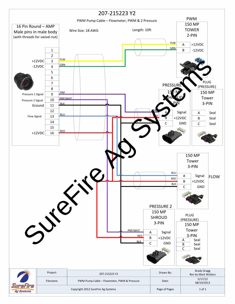
207-215223 Y2
PWM Pump Cable – Flowmeter, PWM & Pressure
Drawn By:
Date:
Brady GraggRev by Mark Wolters
5/17/1208/19/2013
Page of Pages 1 of 1Copyright 2012 SureFire Ag Systems
207-215223 Y2 PWM Pump Cable – Flowmeter, PWM & 2 Pressure
Wire Size: 18 AWG Length: 10ft
A +12VDC
-12VDC
150 MPTOWER2-PIN
YLW
GRNB
A Signal
+12VDC
150 MPSHROUD
3-PIN
PRP
REDB
C GNDBLK
A
+12VDC
GND
150 MPTower3-PIN
RED
BLKB
C
SignalBLU
1
16 Pin Round – AMPMale pins in male body(with threads for swivel nut)
PRP
GRN
2
3YLW
4
5
6
7
8
9
10
11
12
13
14
15
16
PWM
BLK
BLU
RED
PRESSURE 1
+12VDC
-12VDC
FLOW
Pressure 1 Signal
Ground
+12VDC
Flow Signal
PLUG (PRESSURE)
A
150 MPTower3-PIN
B
C
Seal
Seal
Seal
A Signal
+12VDC
150 MPSHROUD
3-PIN
PRP/WHT
REDB
C GNDBLK
PRESSURE 2
PRP/WHT
PLUG (PRESSURE)
A
150 MPTower3-PIN
BC
SealSealSeal
Pressure 2 Signal
SureFire
Ag Sys
tems
markw
Typewritten Text
19
A
Signal
+12VDC
WPTOWER3-PIN
B
CGND
Project:
Filename:
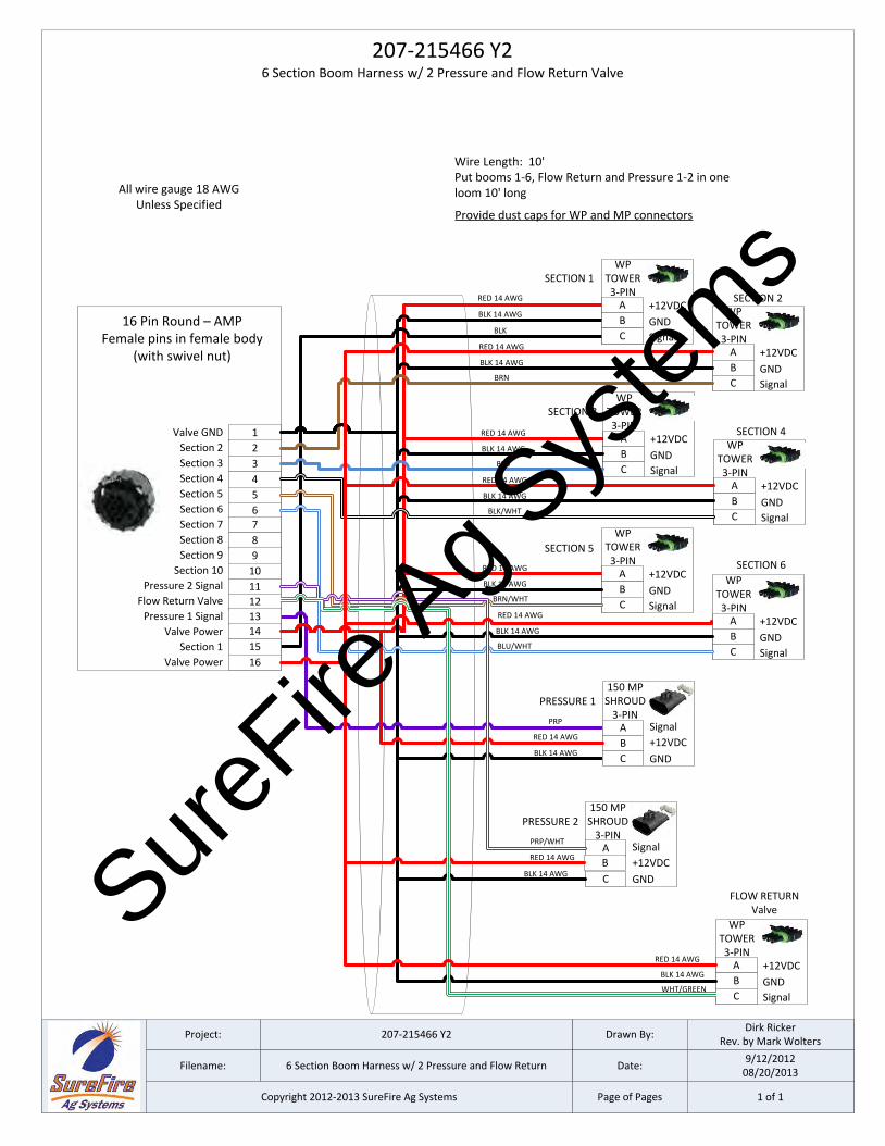
207-215466 Y2
6 Section Boom Harness w/ 2 Pressure and Flow Return
Drawn By:
Date:
Dirk RickerRev. by Mark Wolters
9/12/201208/20/2013
Page of Pages 1 of 1Copyright 2012-2013 SureFire Ag Systems
A
Signal
+12VDC
WPTOWER3-PIN
B
CGND
A
Signal
+12VDC
WPTOWER3-PIN
B
CGND
A
Signal
+12VDC
WPTOWER3-PIN
B
CGND
A
Signal
+12VDC
WPTOWER3-PIN
B
CGND
A
Signal
+12VDC
WPTOWER3-PIN
B
CGND
207-215466 Y26 Section Boom Harness w/ 2 Pressure and Flow Return Valve
B
Signal
+12VDC
150 MPSHROUD
3-PIN
C
A
GND
16 Pin Round – AMPFemale pins in female body
(with swivel nut)
1Valve GND
Section 2 2
3Section 3
4
5
67
8
9
10
11
12
13
14
15
16
Section 4
Section 5
Section 6
Section 7
Section 8
Section 9
Section 10
Pressure 2 Signal
Flow Return Valve
Pressure 1 Signal
Valve Power
Section 1
Valve Power
SECTION 1
SECTION 2
PRESSURE 1
All wire gauge 18 AWG Unless Specified
RED 14 AWG
BLK 14 AWG
BLK
RED 14 AWG
BLK 14 AWG
BRN
RED 14 AWG
BLK 14 AWG
BLU
RED 14 AWG
BLK 14 AWG
BLK/WHT
RED 14 AWG
BLK 14 AWG
BRN/WHT
RED 14 AWG
BLK 14 AWG
BLU/WHT
RED 14 AWG
BLK 14 AWG
PRP
Wire Length: 10'Put booms 1-6, Flow Return and Pressure 1-2 in one loom 10' long
Provide dust caps for WP and MP connectors
SECTION 3
SECTION 4
SECTION 5
SECTION 6
A
Signal
+12VDC
WPTOWER3-PIN
B
CGND
FLOW RETURNValve
Signal
+12VDC
150 MPSHROUD
3-PIN
C
A
GND
PRESSURE 2
BRED 14 AWG
PRP/WHT
BLK 14 AWG
RED 14 AWG
BLK 14 AWG
WHT/GREEN
SureFire
Ag Sys
tems
markw
Typewritten Text
20
396-3053Y1 SureFire Tower 100 for NutriSphere®-N NH3 for Pro 700 21 Revised 04/13/2016
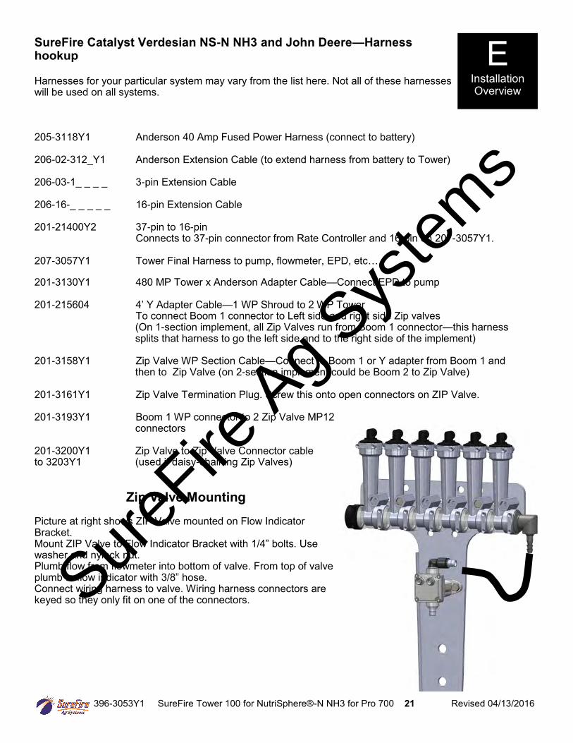
SureFire Catalyst Verdesian NS-N NH3 and John Deere—Harness hookup Harnesses for your particular system may vary from the list here. Not all of these harnesses will be used on all systems. 205-3118Y1 Anderson 40 Amp Fused Power Harness (connect to battery) 206-02-312_Y1 Anderson Extension Cable (to extend harness from battery to Tower) 206-03-1_ _ _ _ 3-pin Extension Cable 206-16-_ _ _ _ _ 16-pin Extension Cable 201-21400Y2 37-pin to 16-pin Connects to 37-pin connector from Rate Controller and 16-pin on 207-3057Y1. 207-3057Y1 Tower Final Harness to pump, flowmeter, EPD, etc… 201-3130Y1 480 MP Tower x Anderson Adapter Cable—Connect EPD to pump 201-215604 4’ Y Adapter Cable—1 WP Shroud to 2 WP Tower To connect Boom 1 connector to Left side and right side Zip valves
(On 1-section implement, all Zip Valves run from Boom 1 connector—this harness splits that harness to go the left side and to the right side of the implement)
201-3158Y1 Zip Valve WP Section Cable—Connect to Boom 1 or Y adapter from Boom 1 and
then to Zip Valve (on 2-section implement could be Boom 2 to Zip Valve) 201-3161Y1 Zip Valve Termination Plug. Screw this onto open connectors on ZIP Valve. 201-3193Y1 Boom 1 WP connector to 2 Zip Valve MP12
connectors 201-3200Y1 Zip Valve to Zip Valve Connector cable to 3203Y1 (used if daisy-chaining Zip Valves)
Zip Valve Mounting Picture at right shows ZIP Valve mounted on Flow Indicator Bracket. Mount ZIP Valve to Flow Indicator Bracket with 1/4” bolts. Use washer and nylock nut. Plumb flow from flowmeter into bottom of valve. From top of valve plumb to flow indicator with 3/8” hose. Connect wiring harness to valve. Wiring harness connectors are keyed so they only fit on one of the connectors.
E Installation Overview
SureFire
Ag Sys
tems
396-3053Y1 SureFire Tower 100 for NutriSphere®-N NH3 for Pro 700 22 Revised 04/13/2016
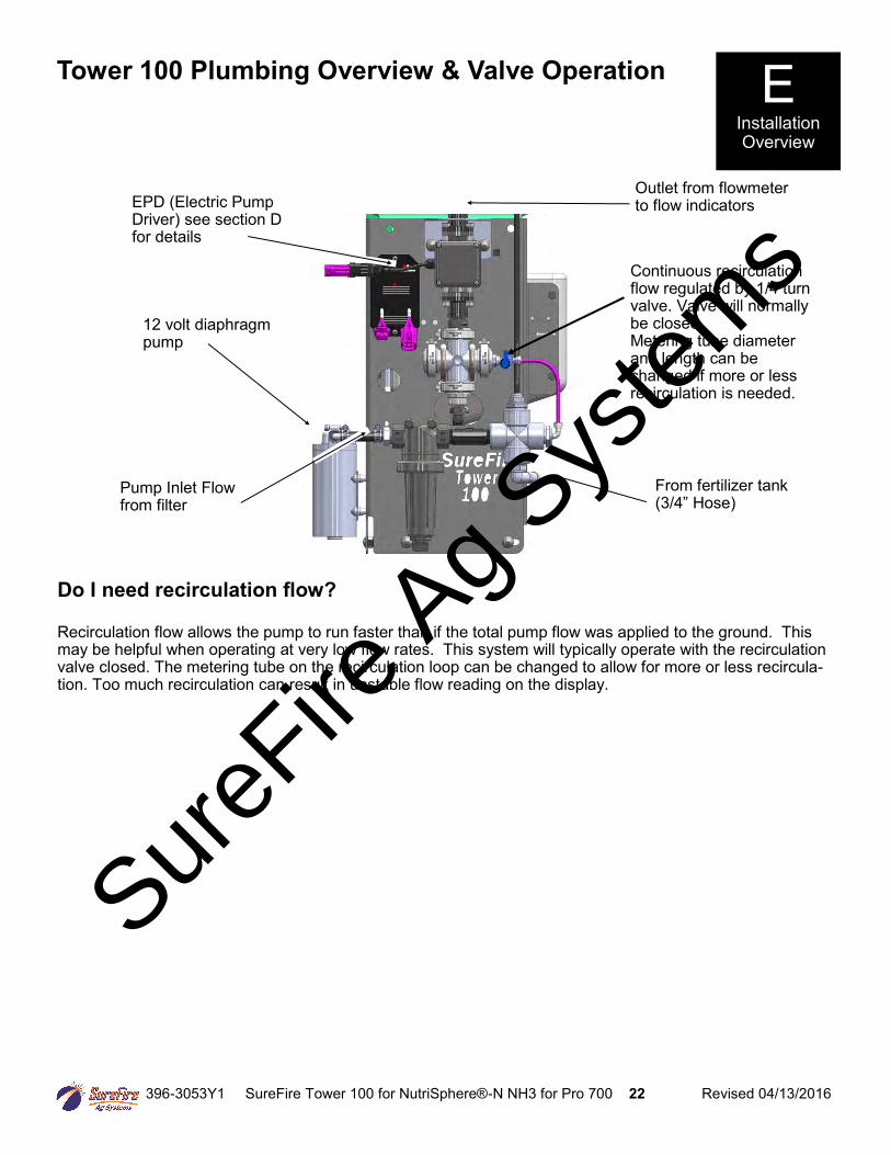
Tower 100 Plumbing Overview & Valve Operation
EPD (Electric Pump Driver) see section D for details
E Installation Overview
12 volt diaphragm pump
Continuous recirculation flow regulated by 1/4 turn valve. Valve will normally be closed. Metering tube diameter and length can be changed if more or less recirculation is needed.
Outlet from flowmeter to flow indicators
From fertilizer tank (3/4” Hose)
Pump Inlet Flow from filter
Do I need recirculation flow? Recirculation flow allows the pump to run faster than if the total pump flow was applied to the ground. This may be helpful when operating at very low flow rates. This system will typically operate with the recirculation valve closed. The metering tube on the recirculation loop can be changed to allow for more or less recircula-tion. Too much recirculation can result in unstable flow reading on the display.
SureFire
Ag Sys
tems
396-3053Y1 SureFire Tower 100 for NutriSphere®-N NH3 for Pro 700 23 Revised 04/13/2016
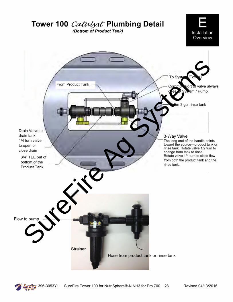
Tower 100 Catalyst Plumbing Detail (Bottom of Product Tank)
3-Way Valve The long end of the handle points toward the source—product tank or rinse tank. Rotate valve 1/2 turn to change from tank to rinse. Rotate valve 1/4 turn to close flow
from both the product tank and the
rinse tank.
Hose from product tank or rinse tank
Flow to pump
Strainer
From 3 gal rinse tank
Common Port of valve always
goes to System / Pump
To System (Tower)
3/4” TEE out of
bottom of the
Product Tank
From Product Tank
Drain Valve to
drain tank—
1/4 turn valve
to open or
close drain
E Installation Overview
SureFire
Ag Sys
tems
396-3053Y1 SureFire Tower 100 for NutriSphere®-N NH3 for Pro 700 24 Revised 04/13/2016
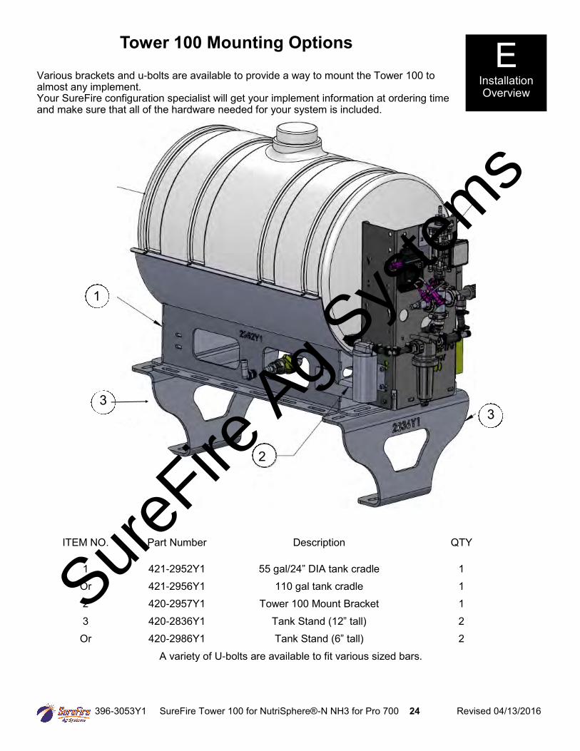
ITEM NO. Part Number Description QTY
1 421-2952Y1 55 gal/24” DIA tank cradle 1 Or 421-2956Y1 110 gal tank cradle 1 2 420-2957Y1 Tower 100 Mount Bracket 1 3 420-2836Y1 Tank Stand (12” tall) 2 Or 420-2986Y1 Tank Stand (6” tall) 2
A variety of U-bolts are available to fit various sized bars.
1
2
3 3
Tower 100 Mounting Options
Various brackets and u-bolts are available to provide a way to mount the Tower 100 to almost any implement. Your SureFire configuration specialist will get your implement information at ordering time and make sure that all of the hardware needed for your system is included.
E Installation Overview
SureFire
Ag Sys
tems
396-3053Y1 SureFire Tower 100 for NutriSphere®-N NH3 for Pro 700 25 Revised 04/13/2016
F Setup &
Operation
AA
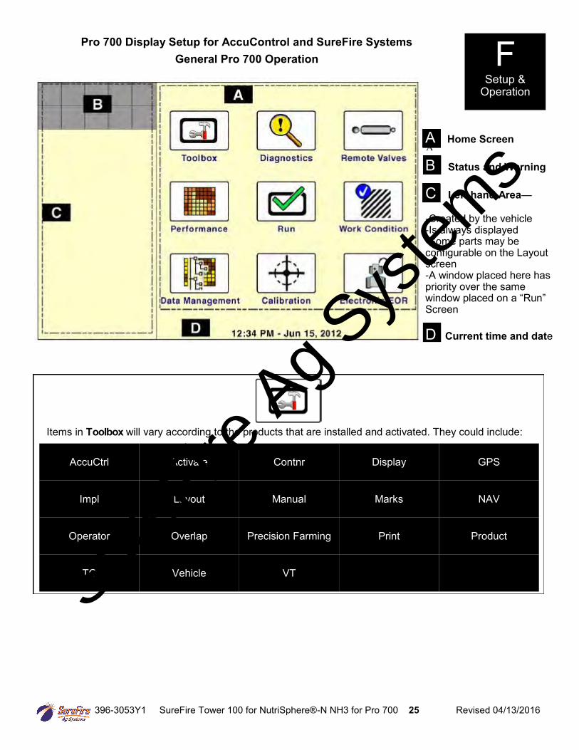
Items in Toolbox will vary according to the products that are installed and activated. They could include:
AccuCtrl Activate Contnr Display GPS
Impl Layout Manual Marks NAV
Operator Overlap Precision Farming Print Product
TC Vehicle VT
Pro 700 Display Setup for AccuControl and SureFire Systems
General Pro 700 Operation
A Home Screen B Status and Warning C Left-hand Area— -Created by the vehicle -Is always displayed -Some parts may be configurable on the Layout screen -A window placed here has priority over the same window placed on a “Run” Screen D Current time and date
SureFire
Ag Sys
tems
396-3053Y1 SureFire Tower 100 for NutriSphere®-N NH3 for Pro 700 26 Revised 04/13/2016
F Setup &
Operation
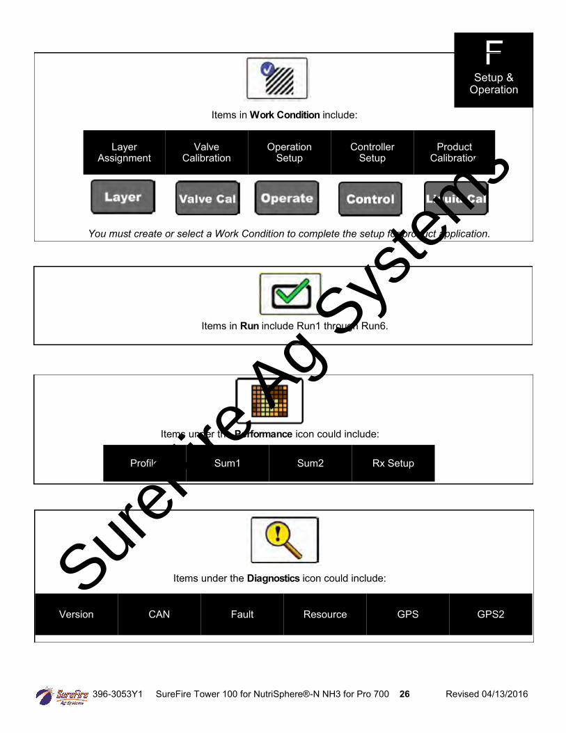
Items in Work Condition include:
Layer Assignment
Valve Calibration
Operation Setup
Controller Setup
Product Calibration
You must create or select a Work Condition to complete the setup for product application.
Items in Run include Run1 through Run6.
Items under the Performance icon could include:
Profile Sum1 Sum2 Rx Setup
Items under the Diagnostics icon could include:
Version CAN Fault Resource GPS GPS2
SureFire
Ag Sys
tems
396-3053Y1 SureFire Tower 100 for NutriSphere®-N NH3 for Pro 700 27 Revised 04/13/2016
F Setup &
Operation
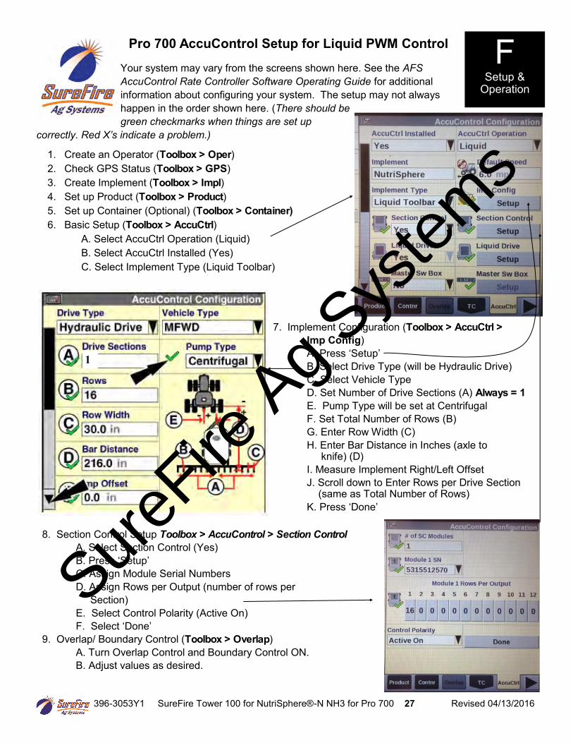
Pro 700 AccuControl Setup for Liquid PWM Control
Your system may vary from the screens shown here. See the AFS
AccuControl Rate Controller Software Operating Guide for additional
information about configuring your system. The setup may not always
happen in the order shown here. (There should be
green checkmarks when things are set up
correctly. Red X’s indicate a problem.)
1. Create an Operator (Toolbox > Oper) 2. Check GPS Status (Toolbox > GPS) 3. Create Implement (Toolbox > Impl) 4. Set up Product (Toolbox > Product) 5. Set up Container (Optional) (Toolbox > Container) 6. Basic Setup (Toolbox > AccuCtrl) A. Select AccuCtrl Operation (Liquid) B. Select AccuCtrl Installed (Yes) C. Select Implement Type (Liquid Toolbar)
1
7. Implement Configuration (Toolbox > AccuCtrl >
Imp Config) A. Press ‘Setup’ B. Select Drive Type (will be Hydraulic Drive) C. Select Vehicle Type D. Set Number of Drive Sections (A) Always = 1
E. Pump Type will be set at Centrifugal F. Set Total Number of Rows (B) G. Enter Row Width (C) H. Enter Bar Distance in Inches (axle to knife) (D) I. Measure Implement Right/Left Offset J. Scroll down to Enter Rows per Drive Section (same as Total Number of Rows) K. Press ‘Done’
8. Section Control Setup Toolbox > AccuControl > Section Control
A. Select Section Control (Yes) B. Press ‘Setup’ C. Assign Module Serial Numbers D. Assign Rows per Output (number of rows per Section) E. Select Control Polarity (Active On) F. Select ‘Done’ 9. Overlap/ Boundary Control (Toolbox > Overlap) A. Turn Overlap Control and Boundary Control ON. B. Adjust values as desired.
SureFire
Ag Sys
tems
396-3053Y1 SureFire Tower 100 for NutriSphere®-N NH3 for Pro 700 28 Revised 04/13/2016
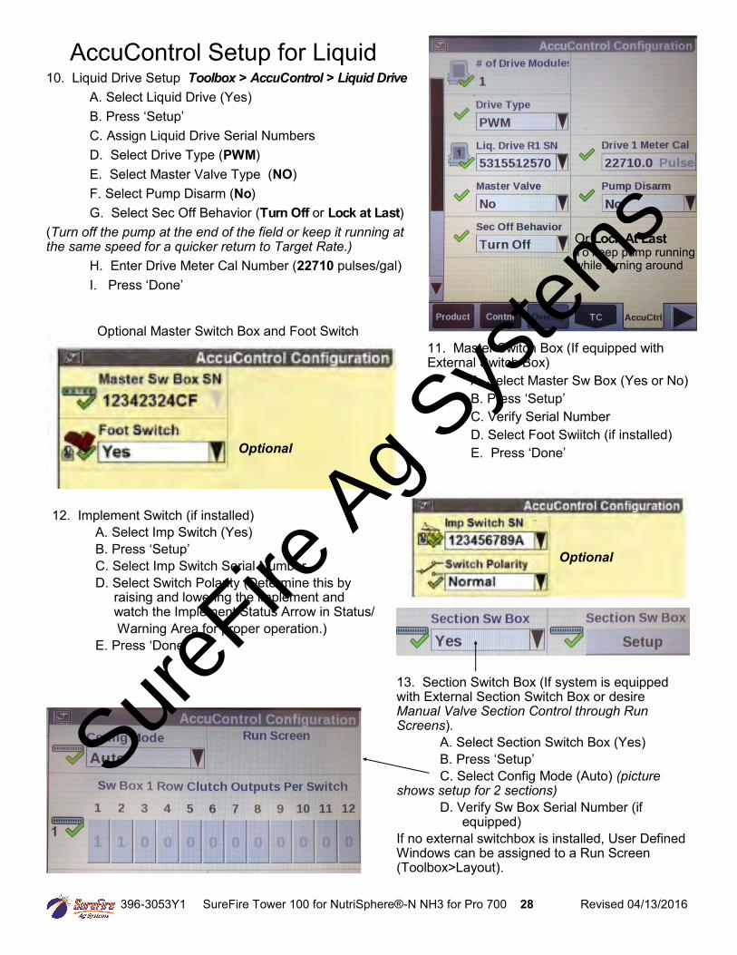
10. Liquid Drive Setup Toolbox > AccuControl > Liquid Drive A. Select Liquid Drive (Yes) B. Press ‘Setup’ C. Assign Liquid Drive Serial Numbers D. Select Drive Type (PWM) E. Select Master Valve Type (NO) F. Select Pump Disarm (No) G. Select Sec Off Behavior (Turn Off or Lock at Last) (Turn off the pump at the end of the field or keep it running at the same speed for a quicker return to Target Rate.)
H. Enter Drive Meter Cal Number (22710 pulses/gal) I. Press ‘Done’
11. Master Switch Box (If equipped with External Switch Box) A. Select Master Sw Box (Yes or No) B. Press ‘Setup’ C. Verify Serial Number D. Select Foot Swiitch (if installed) E. Press ‘Done’
12. Implement Switch (if installed) A. Select Imp Switch (Yes) B. Press ‘Setup’ C. Select Imp Switch Serial Number D. Select Switch Polarity (Determine this by raising and lowering the implement and watch the Implement Status Arrow in Status/ Warning Area for proper operation.) E. Press ‘Done’
13. Section Switch Box (If system is equipped with External Section Switch Box or desire Manual Valve Section Control through Run Screens). A. Select Section Switch Box (Yes) B. Press ‘Setup’ C. Select Config Mode (Auto) (picture shows setup for 2 sections)
D. Verify Sw Box Serial Number (if equipped) If no external switchbox is installed, User Defined Windows can be assigned to a Run Screen (Toolbox>Layout).
AccuControl Setup for Liquid
Optional Master Switch Box and Foot Switch
Or Lock At Last To keep pump running while turning around
Optional
Optional
SureFire
Ag Sys
tems
396-3053Y1 SureFire Tower 100 for NutriSphere®-N NH3 for Pro 700 29 Revised 04/13/2016
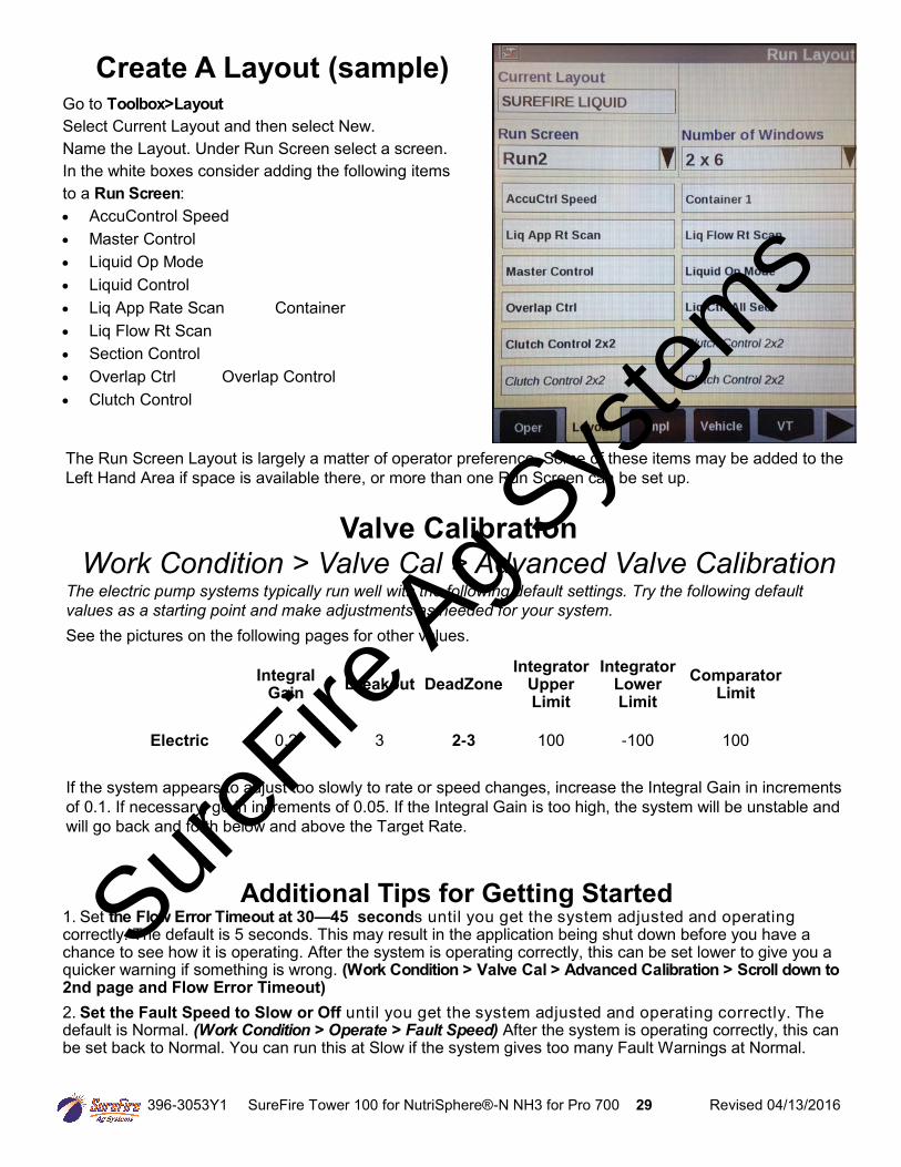
Create A Layout (sample)
Go to Toolbox>Layout Select Current Layout and then select New. Name the Layout. Under Run Screen select a screen. In the white boxes consider adding the following items to a Run Screen: AccuControl Speed Master Control Liquid Op Mode Liquid Control Liq App Rate Scan Container Liq Flow Rt Scan Section Control Overlap Ctrl Overlap Control Clutch Control
The Run Screen Layout is largely a matter of operator preference. Some of these items may be added to the
Left Hand Area if space is available there, or more than one Run Screen can be set up.
Valve Calibration
Work Condition > Valve Cal > Advanced Valve Calibration
The electric pump systems typically run well with the following default settings. Try the following default
values as a starting point and make adjustments as needed for your system.
See the pictures on the following pages for other values. If the system appears to adjust too slowly to rate or speed changes, increase the Integral Gain in increments
of 0.1. If necessary, go in increments of 0.05. If the Integral Gain is too high, the system will be unstable and
will go back and forth below and above the Target Rate.
Additional Tips for Getting Started 1. Set the Flow Error Timeout at 30—45 seconds until you get the system adjusted and operating correctly. The default is 5 seconds. This may result in the application being shut down before you have a chance to see how it is operating. After the system is operating correctly, this can be set lower to give you a quicker warning if something is wrong. (Work Condition > Valve Cal > Advanced Calibration > Scroll down to 2nd page and Flow Error Timeout)
2. Set the Fault Speed to Slow or Off until you get the system adjusted and operating correctly. The default is Normal. (Work Condition > Operate > Fault Speed) After the system is operating correctly, this can be set back to Normal. You can run this at Slow if the system gives too many Fault Warnings at Normal.
Integral Gain
Breakout DeadZone Integrator
Upper Limit
Integrator Lower Limit
Comparator Limit
Electric 0.2 3 2-3 100 -100 100
SureFire
Ag Sys
tems
396-3053Y1 SureFire Tower 100 for NutriSphere®-N NH3 for Pro 700 30 Revised 04/13/2016
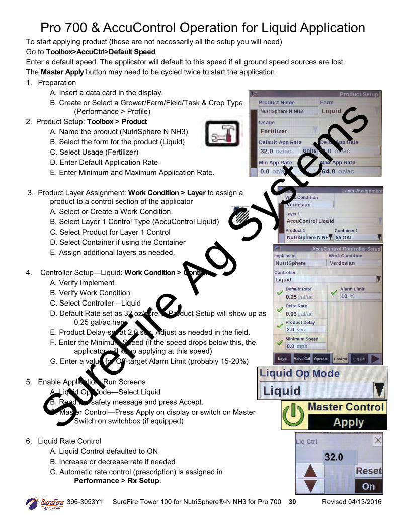
Pro 700 & AccuControl Operation for Liquid Application To start applying product (these are not necessarily all the setup you will need) Go to Toolbox>AccuCtrl>Default Speed
Enter a default speed. The applicator will default to this speed if all ground speed sources are lost. The Master Apply button may need to be cycled twice to start the application. 1. Preparation A. Insert a data card in the display. B. Create or Select a Grower/Farm/Field/Task & Crop Type
(Performance > Profile) 2. Product Setup: Toolbox > Product
A. Name the product (NutriSphere N NH3) B. Select the form for the product (Liquid) C. Select Usage (Fertilizer) D. Enter Default Application Rate E. Enter Minimum and Maximum Application Rate. 3. Product Layer Assignment: Work Condition > Layer to assign a
product to a control section of the applicator A. Select or Create a Work Condition. B. Select Layer 1 Control Type (AccuControl Liquid) C. Select Product for Layer 1 Control D. Select Container if using the Container E. Assign additional layers as needed. 4. Controller Setup—Liquid: Work Condition > Control
A. Verify Implement B. Verify Work Condition C. Select Controller—Liquid D. Default Rate set as 32 oz/acre in Product Setup will show up as
0.25 gal/ac here E. Product Delay-set at 2.0 sec. Adjust as needed in the field. F. Enter the Minimum Speed (if the speed drops below this, the applicator will keep applying at this speed) G. Enter a value for Off-target Alarm Limit (probably 15-20%) 5. Enable Application: Run Screens A. Liquid Op Mode—Select Liquid B. Read the safety message and press Accept. C. Master Control—Press Apply on display or switch on Master Switch on switchbox (if equipped) 6. Liquid Rate Control A. Liquid Control defaulted to ON B. Increase or decrease rate if needed C. Automatic rate control (prescription) is assigned in
Performance > Rx Setup.
32.0
SureFire
Ag Sys
tems

396-3053Y1 SureFire Tower 100 for NutriSphere®-N NH3 for Pro 700 31 Revised 04/13/2016
Possible Run Screen Layout for system with 2 sections
Screen showing Flow Error Timeout set to 45 sec Work Condition > Valve Cal > Advanced Calibration > Scroll down to 2nd page and Flow Error Timeout)
Start with these Valve Cal settings Work Condition > Valve Cal >
Advanced Calibration
Screen showing AccuControl Liquid Drive Setup Toolbox > AccuCtrl > Lquid Drive Setup
To use default AccuCtrl speed, turn Radar off. Toolbox > Vehicle > Radar Installed > NO
Or Lock At Last To keep pump running while turning around
SureFire
Ag Sys
tems
396-3053Y1 SureFire Tower 100 for NutriSphere®-N NH3 for Pro 700 32 Revised 04/13/2016
Frequently Asked Questions (FAQ), Operating Tips, and Troubleshooting Tips for SureFire Catalyst System with
Pro 700 AccuControl 1. Which metering tube should I use? Use the tube (or tubes) that will keep the pressure in the 10 to 20 PSI range. This could change during the day. On a cold morning with cold, thick product it may be necessary to open both tubes. As the product warms up it will get thinner and you may be able to close the gray tube and just use the purple tube. When applying in warm temperatures or at lower speeds the gray tube may work best to keep the pressure in that range. When applying at higher speeds, there is more product going through the tube, so the purple tube or both tubes may be necessary at higher speeds. There is no harm to anything operating at higher pressures, but this system seems to have a more stable flow reading in that 10 to 20 PSI range. Below 8 PSI may result in uneven flow distribution as all the check valves may not open at the same time or to the same degree. The electric pump has a built-in internal bypass at 60 PSI. 2. I’m trying to apply 32 oz/acre. My Target Rate is set at 32 oz/acre. On my Run Screen the Liq App
Rate Scan only shows gal/ac and the Liq Flow Rt Scan shows gpm. How do I know if I’m hitting my rate?
The Pro 700 only shows gallons on the Liq App Rt Scan and the Liq Flow Rt Scan, and it only shows these to 1 decimal place. 32 oz/acre is 0.25 gal/ac. The Liq App Rt Scan should move back and forth between 0.2 and 0.3 gal/ac if it is applying 0.25 gal/ac. At 32 oz/acre on a 40’ implement, the pump output will be 0.1 gpm at 5 mph and 0.2 gpm at 10 mph. The ultimate verification of proper application is if the actual output in a field matches what should have been applied for the number of acres covered. At 32 oz/acre (0.25 gal/ac), 100 acres would take 25 gallons. A catch test can be conducted to verify proper setup and operation. The Pro 700 has a Liquid Calibration sequence (Work Condition > Liq Cal). If doing the AccuControl Liquid Calibration be sure to catch enough output to get a good measurement. At 32 oz/acre, each row is only putting out about 1 oz/min. It would be best to catch the total pump output for several minutes to get a large enough sample volume. The SureFire electromagnetic flowmeter typically measures very accurately. Small adjustments, if any, to the Meter Cal Value are usually sufficient. (Optional workaround to have the Pro 700 show Liq App Rate Scan and Liq Flow Rt Scan in ounces instead of gallons: Set the Flowmeter Cal Value at 177.4 (22710 / 128). It will say 177.4 pulses/gal, but it is actually 177.4 pulses/ounce. The flowmeter will think it is counting gallons, but it is actually counting ounces. Set the Rate at 32 gal/ac. The Liq App Rate Scan and Liq Flow Rate Scan will now show the number of ounces per acre and ounces per minute (but the controller will say and will think it is measuring gallons per acre and gallons per minute). With this setting, the Liq App Rate Scan will jump around some. It should be close to 32, but this will move because of the instantaneous nature of the calculations and the unavoidable momentary variations as the implement goes across the field. 3. Can I use the Pro 700 Valve Calibration procedure to set up my system? Yes (maybe). Work Condition > Valve Cal has a Valve Calibration procedure. On the Pro 700, this may or not may not give values for the various valve calibration parameters that will work. This manual has values that have worked on a number of systems. There is no harm in trying the Valve Cal procedure but it may not always provide a workable setup. Make sure the system is primed and ready for operation before running the Valve Calibration.
SureFire
Ag Sys
tems
396-3053Y1 SureFire Tower 100 for NutriSphere®-N NH3 for Pro 700 33 Revised 04/13/2016
Frequently Asked Questions (FAQ), Operating Tips, and Troubleshooting Tips for SureFire Catalyst System with
Pro 700 AccuControl 4. I keep getting an Error Message and my system stops. For initial setup and during troubleshooting, set the Flow Error Timeout (Work Condition > Valve Cal > scroll to 2nd page) to 45 seconds. This should let the system run long enough to troubleshoot the problem. Also, set the Fault Speed (Work Condition > Operate) to Slow or Off. Some of the Pro 700 error messages are not specific enough to be very helpful. Consider each item listed in the message to try to pinpoint the problem. 5. Which ball should I use in the flow indicator? The green ball will give a good indication for most application scenarios below 8 mph. In cold weather when the product is thicker, the heavier red ball may do better. Basically, if the green works, use it. If you want a heavier ball, use the red one. At the low flow rates of this system, using a heavier ball or using both balls has, at times, created some instability in the flow. 6. The balls in my flow indicators are not at the same level. While giving a good indication of the flow to each row, the balls are not an absolute indicator of exact flow. Repeated catch tests have shown very little row-to-row variation with this system. Uneven balls may be an indication of variation in flow, but only a careful catch test can verify this. Check the plumbing on rows that appear out of line. Switch the tube that is coming out of one flow indicator with another tube and see if the other flow indicator shows the same thing. 7. When I tested the system with water, I couldn’t build any pressure. The metering tubes are designed to work with the NutriSphere N-NH3 product, which has a much higher viscosity than water. When testing the system with water it will be necessary to run a much higher rate to build more pressure. At low rates and low pressure, the check valves may not all open or there may be uneven row-to-row flow. 8. What software/firmware versions should I be running? The latest. Check with your Case dealer to see what the current versions are. It is necessary to update the display software, the AccuControl software, and the Field-IQ firmware, along with any other features you are using. Out of date or mismatched software/firmware versions can cause system operating problems. 9. My system surges above rate and then below rate. Check the Integral Gain in the Advanced Valve Calibration page (Work Condition > Valve Cal > Advanced Calibration). Too high of an Integral Gain will cause the system to surge above and below the rate (like oversteering). Too low of a DeadZone setting can cause some of this also. If the DeadZone is set at 3%, the controller will not make any adjustments to the pump speed if the Applied Rate is within 3% of the Target Rate. On a 32 oz/acre, this would be ± 1 oz. If this is set too low, the controller attempts to adjust to every slight deviation from the Target Rate. This can actually lead to oscillating back and forth across the Target Rate.
SureFire
Ag Sys
tems
396-3053Y1 SureFire Tower 100 for NutriSphere®-N NH3 for Pro 700 34 Revised 04/13/2016
Frequently Asked Questions (FAQ), Operating Tips, and Troubleshooting Tips for SureFire Catalyst System with
Pro 700 AccuControl
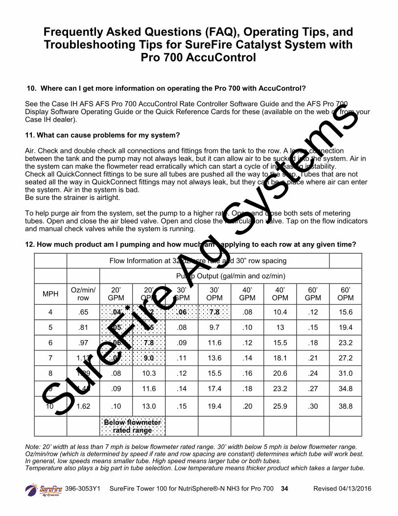
10. Where can I get more information on operating the Pro 700 with AccuControl? See the Case IH AFS AFS Pro 700 AccuControl Rate Controller Software Guide and the AFS Pro 700 Display Software Operating Guide or the Quick Reference Cards for these (available on the web or from your Case IH dealer). 11. What can cause problems for my system? Air. Check and double check all connections and fittings from the tank to the row. A loose connection between the tank and the pump may not always leak, but it can allow air to be sucked into the system. Air in the system can make the flowmeter read erratically which can start a cycle of increasing instability. Check all QuickConnect fittings to be sure all tubes are pushed all the way to the stop. Tubes that are not seated all the way in QuickConnect fittings may not always leak, but they can be a place where air can enter the system. Air in the system is bad. Be sure the strainer is airtight. To help purge air from the system, set the pump to a higher rate. Open and close both sets of metering tubes. Open and close the air bleed valve. Open and close the recirculation valve. Tap on the flow indicators and manual check valves while the system is running. 12. How much product am I pumping and how much am I applying to each row at any given time? Note: 20’ width at less than 7 mph is below flowmeter rated range. 30’ width below 5 mph is below flowmeter range. Oz/min/row (which is determined by speed if rate and row spacing are constant) determines which tube will work best. In general, low speeds means smaller tube. High speed means larger tube or both tubes. Temperature also plays a big part in tube selection. Low temperature means thicker product which takes a larger tube.
Flow Information at 32 oz/acre rate and 30” row spacing
Pump Output (gal/min and oz/min)
MPH Oz/min/row
20’ GPM
20’ OPM
30’ GPM
30’ OPM
40’ GPM
40’ OPM
60’ GPM
60’ OPM
4 .65 .04 5.2 .06 7.8 .08 10.4 .12 15.6
5 .81 .05 6.5 .08 9.7 .10 13 .15 19.4
6 .97 .06 7.8 .09 11.6 .12 15.5 .18 23.2
7 1.13 .07 9.0 .11 13.6 .14 18.1 .21 27.2
8 1.29 .08 10.3 .12 15.5 .16 20.6 .24 31.0
9 1.45 .09 11.6 .14 17.4 .18 23.2 .27 34.8
10 1.62 .10 13.0 .15 19.4 .20 25.9 .30 38.8
Below flowmeter rated range
Sure
Fire Ag S
ystem
s
396-3053Y1 SureFire Tower 100 for NutriSphere®-N NH3 for Pro 700 35 Revised 04/13/2016
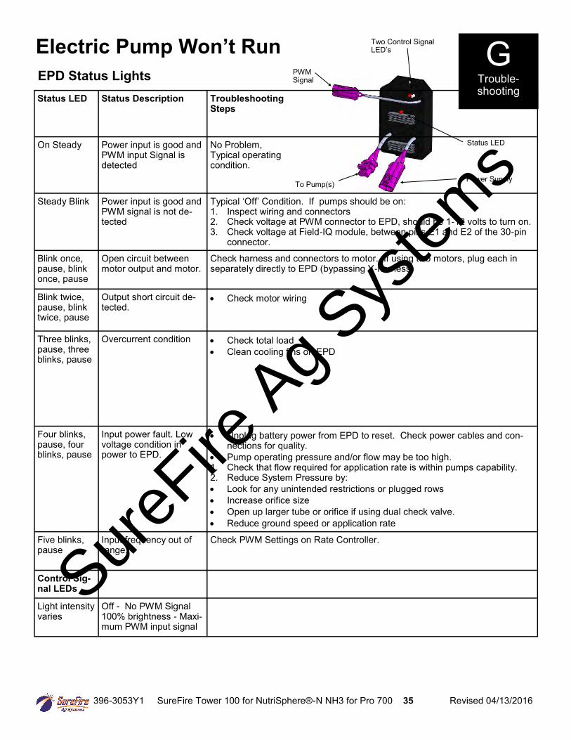
Status LED Status Description Troubleshooting Steps
On Steady Power input is good and PWM input Signal is detected
No Problem, Typical operating condition.
Steady Blink Power input is good and PWM signal is not de-tected
Typical ‘Off’ Condition. If pumps should be on: 1. Inspect wiring and connectors 2. Check voltage at PWM connector to EPD, should be 1-12 volts to turn on. 3. Check voltage at Field-IQ module, between pins E1 and E2 of the 30-pin
connector.
Blink once, pause, blink once, pause
Open circuit between motor output and motor.
Check harness and connectors to motor. If using two motors, plug each in separately directly to EPD (bypassing Y-harness)
Blink twice, pause, blink twice, pause
Output short circuit de-tected.
Check motor wiring
Three blinks, pause, three blinks, pause
Overcurrent condition Check total load Clean cooling fins on EPD
Four blinks, pause, four blinks, pause
Input power fault. Low voltage condition in power to EPD.
Unplug battery power from EPD to reset. Check power cables and con-nections for quality.
Pump operating pressure and/or flow may be too high. 1. Check that flow required for application rate is within pumps capability. 2. Reduce System Pressure by: Look for any unintended restrictions or plugged rows Increase orifice size Open up larger tube or orifice if using dual check valve. Reduce ground speed or application rate
Five blinks, pause
Input frequency out of range.
Check PWM Settings on Rate Controller.
Control Sig-nal LEDs
Light intensity varies
Off - No PWM Signal 100% brightness - Maxi-mum PWM input signal
Electric Pump Won’t Run
EPD Status Lights
To Pump(s)
Two Control Signal LED’s
Status LED
Power Supply
PWM Signal
G Trouble-shooting
SureFire
Ag Sys
tems
396-3053Y1 SureFire Tower 100 for NutriSphere®-N NH3 for Pro 700 36 Revised 04/13/2016
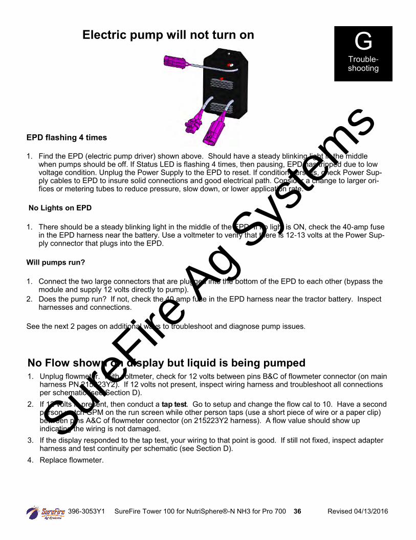
Electric pump will not turn on
EPD flashing 4 times
1. Find the EPD (electric pump driver) shown above. Should have a steady blinking light in the middle when pumps should be off. If Status LED is flashing 4 times, then pausing, EPD has tripped due to low voltage condition. Unplug the Power Supply to the EPD to reset. If condition persists, check Power Sup-ply cables to EPD to insure solid connections and good electrical path. Consider a change to larger ori-fices or metering tubes to reduce pressure, slow down, or lower application rate.
No Lights on EPD
1. There should be a steady blinking light in the middle of the EPD. If no light is ON, check the 40-amp fuse in the EPD harness near the battery. Use a voltmeter to verify that there is 12-13 volts at the Power Sup-ply connector that plugs into the EPD.
Will pumps run?
1. Connect the two large connectors that are plugged into the bottom of the EPD to each other (bypass the module and supply 12 volts directly to pump).
2. Does the pump run? If not, check the 40 amp fuse in the EPD harness near the tractor battery. Inspect harnesses and connections.
See the next 2 pages on additional ways to troubleshoot and diagnose pump issues.
G Trouble-shooting
No Flow shown on display but liquid is being pumped 1. Unplug flowmeter. With voltmeter, check for 12 volts between pins B&C of flowmeter connector (on main
harness PN 215223Y2). If 12 volts not present, inspect wiring harness and troubleshoot all connections per schematic (see Section D).
2. If 12 volts is present, then conduct a tap test. Go to setup and change the flow cal to 10. Have a second person watch GPM on the run screen while other person taps (use a short piece of wire or a paper clip) between pins A&C of flowmeter connector (on 215223Y2 harness). A flow value should show up indicating the wiring is not damaged.
3. If the display responded to the tap test, your wiring to that point is good. If still not fixed, inspect adapter harness and test continuity per schematic (see Section D).
4. Replace flowmeter.
SureFire
Ag Sys
tems
396-3053Y1 SureFire Tower 100 for NutriSphere®-N NH3 for Pro 700 37 Revised 04/13/2016
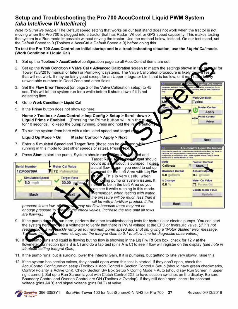
Setup and Troubleshooting the Pro 700 AccuControl Liquid PWM System (aka Intellivew IV Intellirate) Note to SureFire people: The Default speed setting that works on our test stand does not work when the tractor is not moving when the Pro 700 is plugged into a tractor that has Radar, Wheel, or GPS speed capability. This makes testing the system in a Run mode impossible without driving the tractor. Use the method below, instead. On our test stand, set the Default Speed to 0 (Toolbox > AccuCtrl > Default Speed > 0) before doing this. To test the Pro 700 AccuControl on initial startup and in a troubleshooting situation, use the Liquid Cal mode. (Work Condition > Liquid Cal) 1. Set up the Toolbox > AccuControl configuration page so all AccuControl items are set. 2. Set up the Work Condition > Valve Cal > Advanced Calibration screen to match the settings shown in the manual for
Tower (3/3/2016 manual or later) or PumpRight systems. The Valve Calibration procedure is likely to give results that will not work. It may be fairly good except for an Upper Integrator Limit that is too low, or it may have totally unworkable numbers in Dead Zone and other fields.
3. Set the Flow Error Timeout (on page 2 of the Valve Calibration setup) to 45 sec. This will let the system run for a while before it shuts down if it is not detecting flow.
4. Go to Work Condition > Liquid Cal 5. If the Prime button does not show up here:
Home > Toolbox > AccuControl > Imp Config > Setup > Scroll down > Liquid Prime > Enabled. (Pressing the Prime button will run the pump for 10 seconds. To keep the pump running, press and hold the Prime button.)
6. To run the system from here with a simulated speed and target rate: Liquid Op Mode > On Master Control > Apply > Next
7. Enter a Simulated Speed and Target Rate (these can be changed while running in this mode to test other speeds or rates). Press Next.
8. Press Start to start the pump. System should run at Simulated Speed and Target Rate. Measured Output should count up as product is pumped. To see actual flow in gpm, you need to set up a Layout for the Left Area with Liq Flw Rt Scn. This is very useful when diagnosing pump or system issues. It needs to be in the Left Area so you can see it while running in this mode. (Remember, when testing with water, the pressure will be much less than it will be with a fertilizer product. If the
pressure is too low, all the rows may not flow because there may not be enough pressure to open all the check valves. Increase the rate until all rows are flowing.)
9. If the pump does not run here, perform the other troubleshooting tests for hydraulic or electric pumps. You can start the system here and use a voltmeter to verify that there is PWM voltage at the EPD or hydraulic valve. (If it is not reading flow, it will quickly ramp up to maximum pump speed and shut off, giving a “Motor Stalled” error message. To make this happen more slowly, set the Integral Gain to 0.1 to allow time for diagnostic observation.)
10. If the pump runs and liquid is flowing but no flow is showing in the Liq Flw Rt Scn box, check for 12 v at the flowmeter connection (pins B & C) and do a tap test (pins A & C) to see if flow will register on the display (see note in #9 about setting Integral Gain).
11. If the pump runs, but is surging, lower the Integral Gain. If it is pumping, but getting to rate very slowly, raise this. 12. If the system has section valves, they should open when this test is started. If they don’t open, check the
AccuControl Configuration setup (Toolbox > AccuControl > Section Control > Setup {should have green checkmarks, Control Polarity is Active On}). Check Section Sw Box Setup > Config Mode > Auto (should say Run Screen in upper right corner). Set up a Run Screen layout with Clutch Control 2X2 to have section switches on the display. Be sure Boundary Control and Overlap Control are ON (Toolbox > Overlap). If they still don’t open, check for constant voltage (pins A&B) and signal voltage (pins B&C) at valve.
SureFire
Ag Sys
tems
396-3053Y1 SureFire Tower 100 for NutriSphere®-N NH3 for Pro 700 38 Revised 04/13/2016
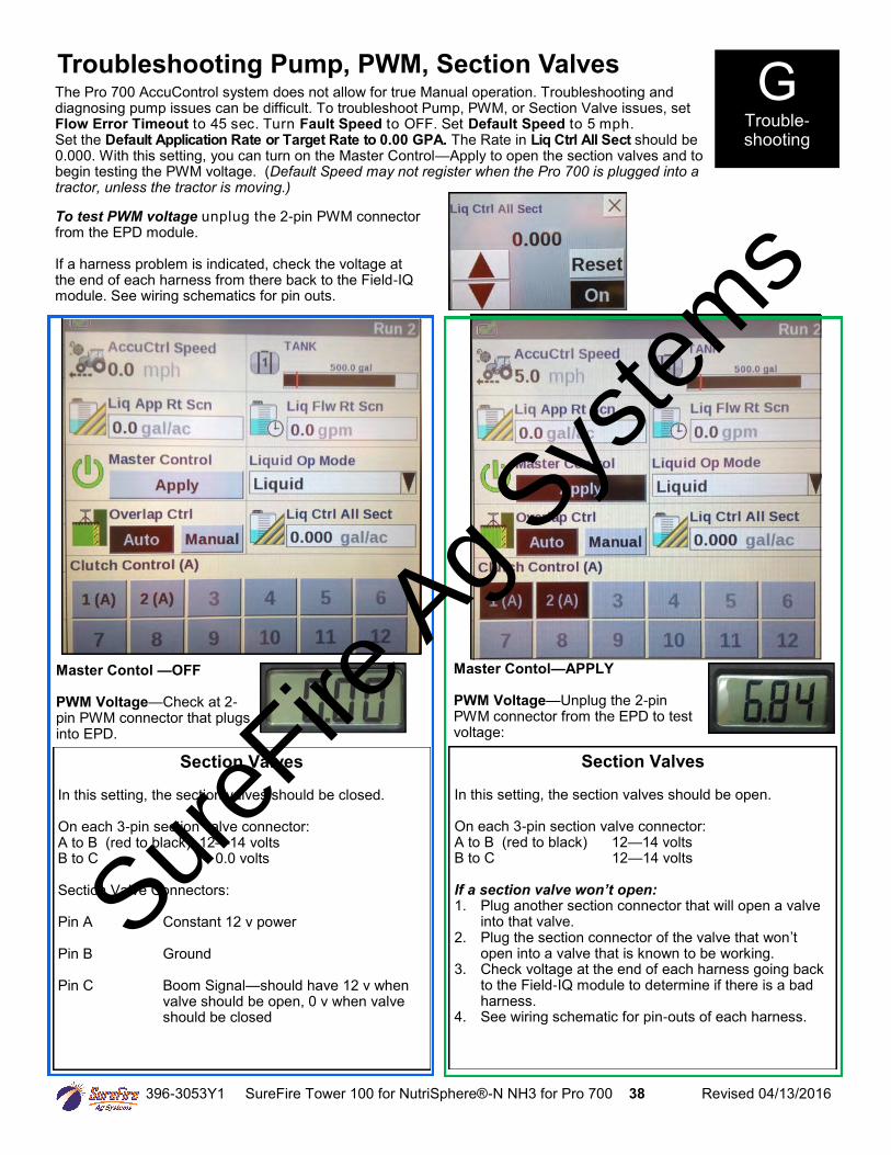
The Pro 700 AccuControl system does not allow for true Manual operation. Troubleshooting and diagnosing pump issues can be difficult. To troubleshoot Pump, PWM, or Section Valve issues, set Flow Error Timeout to 45 sec. Turn Fault Speed to OFF. Set Default Speed to 5 mph. Set the Default Application Rate or Target Rate to 0.00 GPA. The Rate in Liq Ctrl All Sect should be 0.000. With this setting, you can turn on the Master Control—Apply to open the section valves and to begin testing the PWM voltage. (Default Speed may not register when the Pro 700 is plugged into a tractor, unless the tractor is moving.)
G Trouble-shooting
To test PWM voltage unplug the 2-pin PWM connector from the EPD module. If a harness problem is indicated, check the voltage at the end of each harness from there back to the Field-IQ module. See wiring schematics for pin outs.
Master Contol —OFF PWM Voltage—Check at 2-pin PWM connector that plugs into EPD.
Master Contol—APPLY PWM Voltage—Unplug the 2-pin PWM connector from the EPD to test voltage:
Section Valves In this setting, the section valves should be closed. On each 3-pin section valve connector: A to B (red to black) 12—14 volts B to C 0.0 volts Section Valve Connectors: Pin A Constant 12 v power Pin B Ground Pin C Boom Signal—should have 12 v when valve should be open, 0 v when valve should be closed
Section Valves In this setting, the section valves should be open. On each 3-pin section valve connector: A to B (red to black) 12—14 volts B to C 12—14 volts If a section valve won’t open: 1. Plug another section connector that will open a valve
into that valve. 2. Plug the section connector of the valve that won’t
open into a valve that is known to be working. 3. Check voltage at the end of each harness going back
to the Field-IQ module to determine if there is a bad harness.
4. See wiring schematic for pin-outs of each harness.
Troubleshooting Pump, PWM, Section Valves
SureFire
Ag Sys
tems
396-3053Y1 SureFire Tower 100 for NutriSphere®-N NH3 for Pro 700 39 Revised 04/13/2016
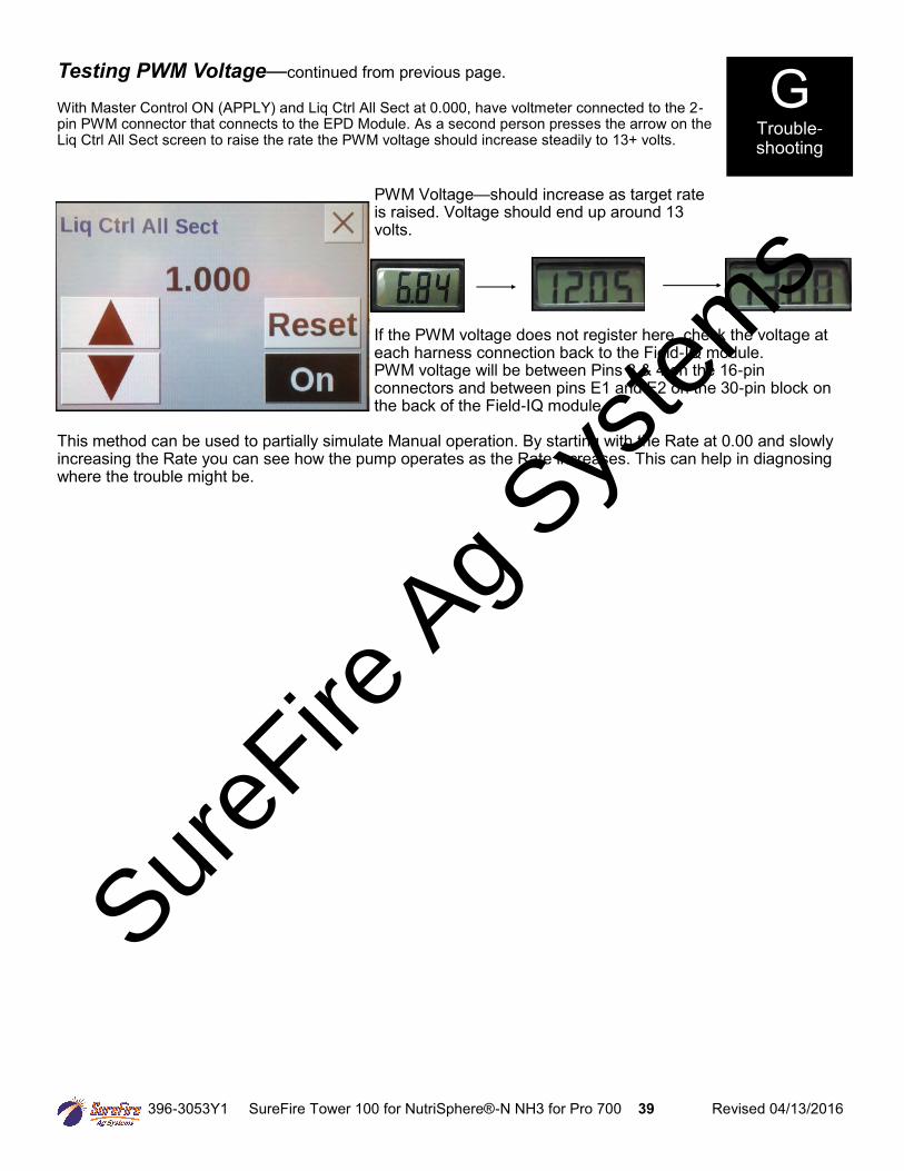
If the PWM voltage does not register here, check the voltage at each harness connection back to the Field-IQ module. PWM voltage will be between Pins 3 & 4 on the 16-pin connectors and between pins E1 and E2 on the 30-pin block on the back of the Field-IQ module.
This method can be used to partially simulate Manual operation. By starting with the Rate at 0.00 and slowly increasing the Rate you can see how the pump operates as the Rate increases. This can help in diagnosing where the trouble might be.
PWM Voltage—should increase as target rate is raised. Voltage should end up around 13 volts.
G Trouble-shooting
Testing PWM Voltage—continued from previous page. With Master Control ON (APPLY) and Liq Ctrl All Sect at 0.000, have voltmeter connected to the 2-pin PWM connector that connects to the EPD Module. As a second person presses the arrow on the Liq Ctrl All Sect screen to raise the rate the PWM voltage should increase steadily to 13+ volts.
SureFire
Ag Sys
tems
396-3053Y1 SureFire Tower 100 for NutriSphere®-N NH3 for Pro 700 40 Revised 04/13/2016
Application Rate Fluctuates Due to the very low application rate used on this system, pump speed changes must be made very slowly since even small changes in pump speed will result in a relatively large change in flow. The controller needs to be set with a very low Valve Calibration number (Integral Gain) so that it can lock onto the rate without continually overshooting and undershooting. This means that the controller will react slower on startup and on larger speed changes. Any system will have minor rate fluctuations going across the field. This is normal and may show up more when applying at very low rates as this system does. First, you need to determine if the fluctuation is caused by the controller sending fluctuating signals to the valve. 1. Set the DeadZone at 3%. (Work Condition > Valve Cal > Advanced Calibration) If the DeadZone is too
low, the controller attempts to adjust every time the rate deviates even a small amount. This can cause the system to start oscillating and actually create more error.
2. Decrease the Integral Gain. (Work Condition > Valve Cal > Advanced Calibration) 3. Are the floating balls slowly going up and down? This low rate system works better when just one ball is in
the flow indicator. Use the green ball unless conditions dictate a heavier ball (red). Also, sometimes the flowmeter sensitivity indicates output changes that don’t translate into actual fluctuation in output at the row. Is the output at the row fluctuating?
4. Inspect & clean pump inlet strainer. Strange flow rate fluctuations are very often due to an obstruction to the pump inlet. Inspect plumbing from tank to pump.
5. Consider if there is air getting into the system. Air going through the flowmeter will cause erratic flowmeter readings, which in turn will cause the controller to start surging as it tries to chase the fluctuating flowmeter readings.
6. What is the pressure? Pressure that is under 8 PSI may mean that not all check valves are opening and staying open. This can cause fluctuations in flow. If the pressure is over 60 PSI, the internal bypass in the pump may be opening. This system has shown more stable flow when operated between 10 and 20 PSI. Use the largest tube or tubes that will keep the pressure above 10 PSI.
7. If recirculation valve is open, try running it with this valve closed (or vice versa). 8. Try operating the system at a lower rate or speed and building up to the desired rate and speed. See
chart on page XX to see if desired output is below the range of the flowmeter. Outputs near or below the range of the flowmeter may cause fluctuation as the output goes in and out of flowmeter range.
Application Rate & Flow Troubleshooting G Trouble-shooting
Application Rate is slow to get to the Target Rate (Due to the very low application rate used on this system, the controller needs to be set with a very low Valve Calibration number (Integral Gain) so that it can lock onto the rate without continually overshooting and undershooting. This means that the controller will react slower on startup and on larger speed changes.)
1. You may need to increase the Integral Gain. Go to Work Condition > Valve Cal > Advanced Calibration.
(Note: Increasing the Integral Gain to speed up control changes may result in the system being unstable at normal operating speed.)
2. Increase the Minimum PWM setting (Work Condition > Valve Cal > Advanced Calibration > scroll down to 2nd page > Advanced PWM > Minimum PWM %). The system will get to Target Rate faster on startup if the Minimum PWM is close to the operating rate. However, the Minimum PWM setting sets the lowest speed that the pump will run, so if the Minimum PWM is too high, the pump will not be able to slow down enough to reach the lowest rate and speed output.
SureFire
Ag Sys
tems
396-3053Y1 SureFire Tower 100 for NutriSphere®-N NH3 for Pro 700 41 Revised 04/13/2016
Winterization
SureFire recommends flushing your product pump and complete system with adequate amounts of water first. Next, use RV antifreeze to winterize your system by pumping an adequate amount through all components. At the beginning of the next season, begin with water to verify the system is in working order with no leaks.
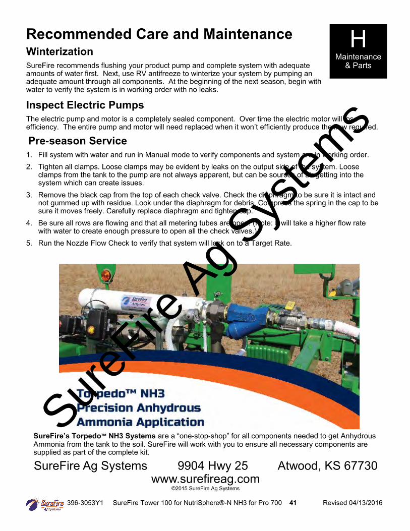
Inspect Electric Pumps
The electric pump and motor is a completely sealed component. Over time the electric motor will lose efficiency. The entire pump and motor will need replaced when it won’t efficiently produce the flow required.
Pre-season Service
1. Fill system with water and run in Manual mode to verify components and system are in working order. 2. Tighten all clamps. Loose clamps may be evident by leaks on the output side of the system. Loose
clamps from the tank to the pump are not always apparent, but can be sources of air getting into the system which can create issues.
3. Remove the black cap from the top of each check valve. Check the diaphragm to be sure it is intact and not gummed up with residue. Look under the diaphragm for debris. Compress the spring in the cap to be sure it moves freely. Carefully replace diaphragm and tighten cap.
4. Be sure all rows are flowing and that all metering tubes are open. (Note: It will take a higher flow rate with water to create enough pressure to open all the check valves.)
5. Run the Nozzle Flow Check to verify that system will lock on to a Target Rate.
Recommended Care and Maintenance H Maintenance
& Parts
SureFire Ag Systems 9904 Hwy 25 Atwood, KS 67730 www.surefireag.com
©2015 SureFire Ag Systems
SureFire’s Torpedo™ NH3 Systems are a “one-stop-shop” for all components needed to get Anhydrous Ammonia from the tank to the soil. SureFire will work with you to ensure all necessary components are supplied as part of the complete kit.
SureFire
Ag Sys
tems

396-3053Y1 SureFire Tower 100 for NutriSphere®-N NH3 for Pro 700 42 Revised 04/13/2016
SureFire
Ag Sys
tems