
39245203 intro-es-iv
35
Other Hardware Units • Power Supply • Clock Oscillator • Reset Circuits • I/O Ports, Buses, Interfaces • LCD & LED Displays • Keypad / Keyboard • Memories • Real Time Clock • Watchdog Timer • Interrupt Handlers • D/A Converter (PWM) • A/D Converter
-
Upload
embeddedbvp -
Category
Documents
-
view
71 -
download
0
Transcript of 39245203 intro-es-iv

Other Hardware Units
• Power Supply• Clock Oscillator• Reset Circuits• I/O Ports, Buses,
Interfaces
• LCD & LED Displays• Keypad / Keyboard
• Memories• Real Time Clock
• Watchdog Timer• Interrupt Handlers• D/A Converter
(PWM)• A/D Converter
Power Supply • Most Systems have their Power Supply with
5.0V +/- 0.25V; 3.3V +/- 0.3V; 2.0V +/- 0.2V 1.5V +/- 0.2VAdditionally, 12V +/- 0.2V may be needed for RS232 serial interface, EEPROM or Flash.
• External I/O , Timers, Clock and Reset Circuits should be should separately powered
• Ceramic Disc Capacitors placed near Vcc & Gnd of each IC to bypass Radio Frequency Interference
Power Supply from external source…..
• Some Systems do not have a power Source of their own and connect to an external Supply.Examples: Network Interface Card, Graphics Accelerator Card in Personal Computer
• Some are Powered by use of a Charge Pump. Like RTS Signal in case of ‘Mouse’ in Computer
• Contact less Smart Cards use radiation based Charge Pump when used with Host Machine

To reduce the Power dissipation
• Use 3.3V supply instead of 5.0V and save power up-to 50%
• Operate system at lowest possible voltage during ‘Idle’ state by selecting a Power Down Mode
• Disable use of certain hardware blocks when not needed (Caches memory) by processor or during a particular Code Execution (Timers or I/O Units)
• Avoid unnecessary glitches and frequent input changes to CMOS logic gates.

Power Saving Modes Using “Stop” States• Processor enters into ‘Stop’ state after:
(i) It receives a “Stop” Instruction
(ii) Disabling Clock inputs to processor
(iii)Stopping the external clock circuit function
(iv) Auto Shut-down operation• Processor can go to ‘Run’ Mode after receiving:
(i) A User Interrupt
(ii) Periodic Wake-up Interrupt
Power Saving Modes Using “Wait” States• Processor enters into ‘Wait’ state after:
(i) It receives a “Wait” Instruction which slows down or disables Clock inputs to ALU.
(ii) While external clock circuit is non-functional,
Timer and DRAM continue to receive clock.
• Processor can go to ‘Run’ Mode after receiving:
(i) An Interrupt or
(ii) A “Reset” Signal

Power Saving due to reduction of Clock frequency
• Power Consumption reduces in CMOS typically 2.5 mW per 100 kHz.
• Reduction in clock from 8000 kHz to 100 kHz can reduce power by 200 mW.
• Heat Generation reduces• RF Interference also reduces • Processor may take longer time to execute code
which may be acceptable during “Idle” time.

Clock Oscillator
• Clock controls the various timing requirements of:• Processor, Timers and Machine Cycles for
fetching, decoding, executing, storing results• Uses external Crystals or Int. Ceramic Resonator• Crystals offer highest frequency stability with
variation in temperature, Voltage and with Aging
• Crystal Oscillator has higher driving capability as needed in Multiprocessors systems to control and synchronize clocks to all processors

Real Time Clock
• A suitably configured Timer Circuit is called System Clock / Real Time Clock (RTC)
• RTC used by Scheduler for real time processing
• Assume a µP generates clock output every 0.5 µS. If Timer is configured by S/W to issue Timeout interrupts (ticks) after every 200 clock input, causing RTC tick rate of 10 kHz.
• RTC Interrupt / Tick is generated every 100 µS
• RTC is also used to obtain S/W controlled delays and Timeouts.

Timers / Counters
• Each Timer has Clock, Gate and Output signals • 8 / 16 Bit Timers / Counters cab be cascaded• Configurable by software in following operating
Modes thru ‘Command’ and ‘Status’ Registers
(1) Time Out Interrupt Generation,
(2) Divide by N Counter / Square wave Generator
(3) Hardware triggered Mono-shot
(4) Software triggered Mono-shot

Reset Circuits
• Power-on-Reset causes processor to begin program execution from a pre-defined Starting address in the program counter (default address)
• “Reset” generated for a fixed clock cycles. • Reset activated by any one of the followings:
(1) External Power-On Reset Circuit
(2) On detection of low voltage on supply (LVDI)
(3) Software Instruction
(4) Timeout by Watchdog Timer due to a fault

Watchdog Timer (WDT)
• Watchdog Timer resets the system after a predetermined timeout – during fault.
• Recovers the system if Program gets stuck. Faults may develop in system due to:
(1) Processor loosing memory reference due to noise spike on Address, Data and / or Control Bus
(2) A sensor getting damaged
(3) Actuator control circuit turns faulty during ‘run’ • Most µC have the Watchdog Timers

Types of Memories
• Internal RAM: 256 or 512 byte for Registers, Temporary Data and Stack
• Internal ROM / PROM: 4 to 16 kB of µC Program• Internal Caches in certain µP• EEPROM / Flash: To save result, system status,
Camera Images, Songs, Speeches after a suitable format compression
• External ROM: For Embedded Software in µP• RAM memory buffer at the ports• External Caches: In Super scalar µP

Input Ports• Inputs Signals from physical devices
Key Buttons,
Sensors & Transducers,• Inputs from Communication system
Network Card
Fax Modem
Broadcasting Service• System gets Inputs by ‘Read’ operation at the port
address
Output Ports• Output Devices
– LCD and LED– Printer– Alarms, Actuators– Communication Systems or Network
• System sends outputs through ‘Write’ operation to port addresses
Interrupt Controllers
• Interrupts are asynchronous H/W events generated by external devices or peripherals in the system
• Processor responds by an appropriate ISR for each device requesting attention
• Certain Interrupt sources are Non-maskable and therefore have highest priority
• Scheduler always gives priority to ISR over the tasks of normal operation

A/D Converters
• 8, 10, 12 bit A/D serial or parallel Converter • Need Start Conversion Command from processor
• Generate End of Conversion Interrupt to µP / µC• Principle of Operation:
– Successive Approximation (25 µS)
– Flash Converter (Less than a µS)– Sigma Delta Converter (several mS)

Keypad
• Keypad is read using input port• 3 Steps to read a key depression event
– Detection of Key pressing event– Debouching– Encoding the value of key

PC Address
2 Bytes for address from where execution starts during Power-On Reset
SP Address
2 Bytes for address of Stack On Reset
Interrupt Service Routine Vector Addresses of 2 bytes each
Boot-up Program Codes
Bytes for Machine Code for RTOS
Bytes for data as Input to Program
Bytes for Machine specific Codes for each program, task, and ISR
System ROM Memory

Types of Languages:
• Machine Language• Assembly Language• High Level Language
– C,
– C++– Java

Selection of Language
• Code Density• Time Density
• Development time• Programming Skills• Portability
• Complexity

Programming in Machine Language
• Used in specific situations like configuring a Physical Device or a Sub-system
• Programmer must understand the Processor, Memorize Instruction Set and Machine code
• Very difficult and Time consuming. • Not portable – Dedicated to hardware

Assembly Language
• Programmer must have thorough understanding of (i) Processor Architecture and
(ii) Instruction Set.
• Compact Code generated
• Minimum Execution time

Assembly Language
Useful to write Assembly code for: • Simple / Small systems
Toys, Robot Arm, Data Acquisition system, Chocolate Vending Machine
• Configuring physical devices likePorts, Display, ADC, DAC, Reading into or transmitting from a buffer, device driver code

High Level Language ‘C’:
• For most systems, C is a preferred language. • Programs written in C are
fast, portable, robust and efficient• Well suited to structured programming• has a rich set of library functions,
• Extendable: add our own functions to library• C Programs have capability of an Assembly
language with all features of High level language
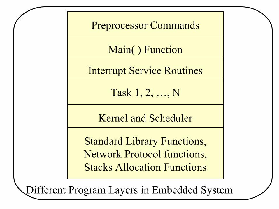
Preprocessor Commands
Main( ) Function
Interrupt Service Routines
Task 1, 2, …, N
Kernel and Scheduler
Standard Library Functions,Network Protocol functions,Stacks Allocation Functions
Different Program Layers in Embedded System

Programming Languages used in new Emb Designs
0.0%
10.0%
20.0%
30.0%
40.0%
50.0%
60.0%
70.0%
80.0%
90.0%
Assembly C C++ Java Other
1998-19991999-2000

Development Tools needed:
• Editors, Cross-Assemblers, • Compiler, Cross Compilers, linkers,
• Simulator, In-circuit Emulators,• Integrated Development Environment (IDE)• OS: Windows 2000; XP or Unix
• RTOS: RT Linux, VxWorks, Win CE, QNX

Use of Real-Time Kernels in New Embedded Designs.
0.0%
20.0%
40.0%
60.0%
80.0%
100.0%
4-bit 8-bit 16-bit 32-bit 64-bit Special

The build and load process for desktop application program
CompilerCompiler
AssemblerAssembler
LinkerLinker
LoaderLoader
Read-WriteMemory (RAM)
Read-WriteMemory (RAM)
Operating System Image: BootProcess
BootProcess
Object Files
Executable Image File

The build and load process for embedded application program
Cross Linker
Cross Linker
Real-Time Kernel: Target Programme
rs
Target Programme
rs
Object Files
Executable Image File
ROM Image
FileCross Compiler
Cross Compiler
Cross Assembler
Cross Assembler
Read-Write Memory (RAM)
Read-Write Memory (RAM)
Flash/EPROM/Read-
Only Memory (ROM)
Flash/EPROM/Read-
Only Memory (ROM)
Program Initialization

Applications – Small scale Embedded System
• Washing Machine• Keyboard Controller
• Serial Ports Card• Computer Mouse• CRT Display Controller
• Remote Controller of TV• Microcontroller based Digital Panel meters for
Voltage, Current, resistance, Frequency

Applications - Medium Scale Emb. Systems• Computer Networking Systems:
Firewall / Router, Switch, Bridge, Hub, Gateway, Front End Processor in a server,
• Attitude & Orbit Control Electronics in Satellites• Banking System- ATM & credit card transaction• Communication: Mobile Phone, Cable TV terminal• Image Processing, Pattern Recognizers, Filtering,
Speech and Video processing• DNA Sequence and Pattern Storage Card and DNA
Pattern Recognizer

Applications - Sophisticated Emb Systems
• Wireless LAN and convergent technology devices• Real time Video/ Speech, Multimedia processing• Security Products & High speed network security
Gigabit rate encryption rate products• Interface & Networking systems using high speed
400 MHz plus, Ultra high speed 10 Gbps and large bandwidth: Routers, LANs, Switches, Gateways, WAN
• Space exploration: the Mars Pathfinder


