38GXM/40GXM Service Training. GXM XPOWER MULTI HIGH WALL SYSTEM Up to 14.5 SEER (18K to 30K) Heat...
38
38GXM/40GXM Service Training
-
Upload
craig-lawther -
Category
Documents
-
view
216 -
download
2
Transcript of 38GXM/40GXM Service Training. GXM XPOWER MULTI HIGH WALL SYSTEM Up to 14.5 SEER (18K to 30K) Heat...
38GXM/40GXM Service Training
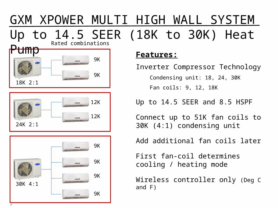
GXM XPOWER MULTI HIGH WALL SYSTEMUp to 14.5 SEER (18K to 30K) Heat Pump
2
18K 2:1
24K 2:1
Rated combinations
9K
9K
12K
12K
30K 4:1
9K
9K
9K
9K
Features:
Inverter Compressor Technology
Condensing unit: 18, 24, 30K
Fan coils: 9, 12, 18K
Up to 14.5 SEER and 8.5 HSPF
Connect up to 51K fan coils to 30K (4:1) condensing unit
Add additional fan coils later
First fan-coil determines cooling / heating mode
Wireless controller only (Deg C and F)
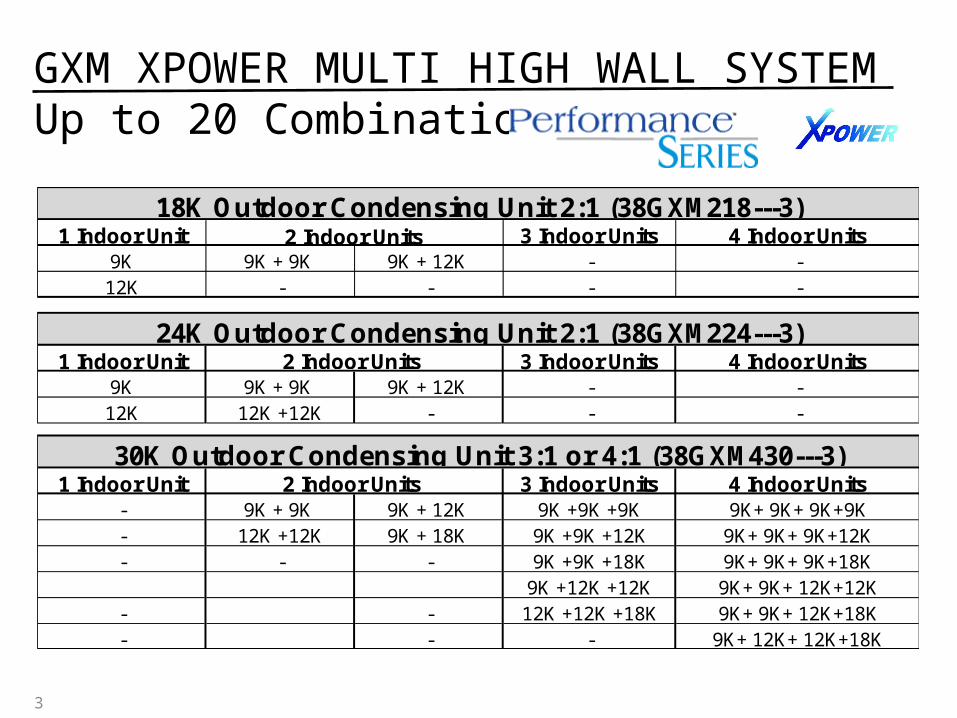
1 Indoor Unit 3 Indoor Units 4 Indoor Units9K 9K + 9K 9K + 12K - -12K - - - -
1 Indoor Unit 3 Indoor Units 4 Indoor Units9K 9K + 9K 9K + 12K - -12K 12K +12K - - -
1 Indoor Unit 3 Indoor Units 4 Indoor Units- 9K + 9K 9K + 12K 9K +9K +9K 9K+ 9K+ 9K+9K- 12K +12K 9K + 18K 9K +9K +12K 9K+ 9K+ 9K+12K- - - 9K +9K +18K 9K+ 9K+ 9K+18K
9K +12K +12K 9K+ 9K+ 12K+12K- - 12K +12K +18K 9K+ 9K+ 12K+18K- - - 9K+ 12K+ 12K+18K
2 Indoor Units
2 Indoor Units 18K Outdoor Condensing Unit 2:1 (38GXM218---3)
24K Outdoor Condensing Unit 2:1 (38GXM224---3)2 Indoor Units
30K Outdoor Condensing Unit 3:1 or 4:1 (38GXM430---3)
3
GXM XPOWER MULTI HIGH WALL SYSTEMUp to 20 Combinations
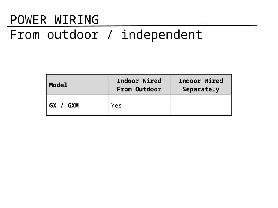
Model Indoor Wired From Outdoor
Indoor Wired Separately
GX / GXM Yes
POWER WIRINGFrom outdoor / independent
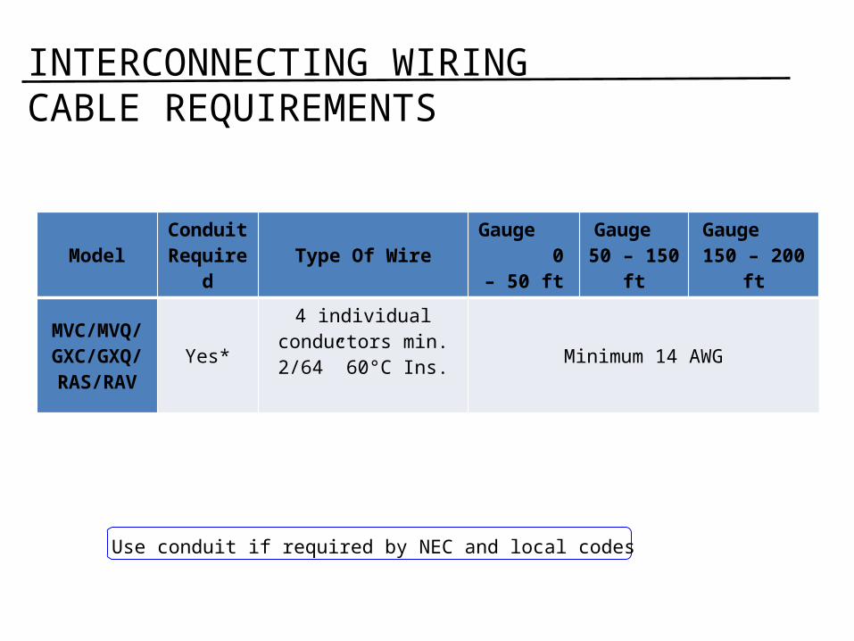
INTERCONNECTING WIRING CABLE REQUIREMENTS
Model Conduit Required Type Of Wire Gauge
0 – 50 ftGauge
50 – 150 ftGauge
150 – 200 ft
MVC/MVQ/GXC/GXQ/
RAS/RAV
Yes*
4 individual conductors min. 2/64”
60°C Ins. Minimum 14 AWG
Back to main menu
Use conduit if required by NEC and local codes

System GXM (Multi)
ºC/ºF convertible
Yes
Timer 12 Hour
Range 25 feet
Dedicated AC or HP
HP Only
Standard / Optional
Standard
USER INTERFACEWireless controllers - Carrier
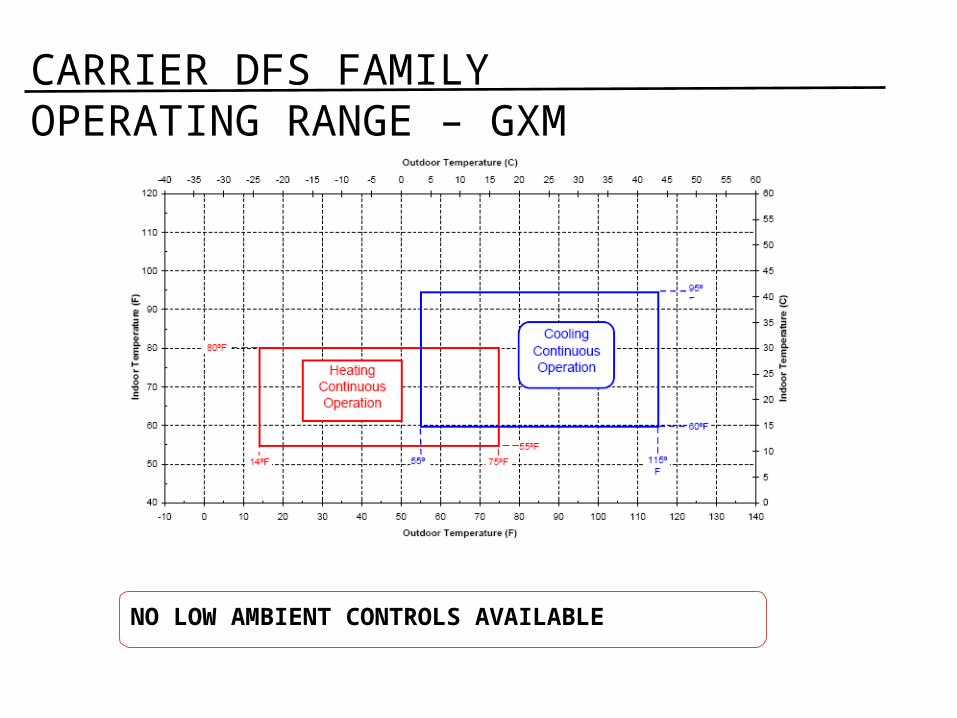
CARRIER DFS FAMILY OPERATING RANGE – GXM
NO LOW AMBIENT CONTROLS AVAILABLE
Refrigeration Components
Metering Device – Electronic Expansion Valves in Outdoor Unit
Reversing Valve – Energized in Heating
Back to main menu
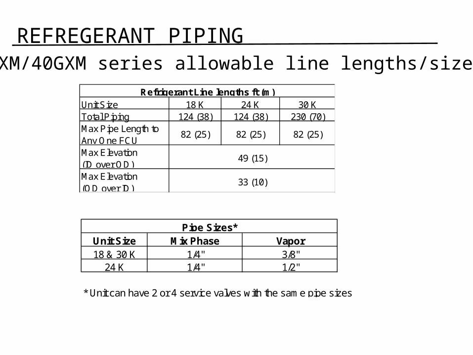
REFREGERANT PIPING 38GXM/40GXM series allowable line lengths/sizes
Unit Size 18 K 24 K 30 KTotal Piping 124 (38) 124 (38) 230 (70)Max Pipe Length to Any One FCU
82 (25) 82 (25) 82 (25)
Max Elevation (ID over OD)Max Elevation (OD over ID)
49 (15)
33 (10)
Refrigerant Line lengths ft (m)
Unit Size Mix Phase Vapor18 & 30 K 1/4" 3/8"
24 K 1/4" 1/2"
* Unit can have 2 or 4 service valves with the same pipe sizes
Pipe Sizes*
Back to main menu
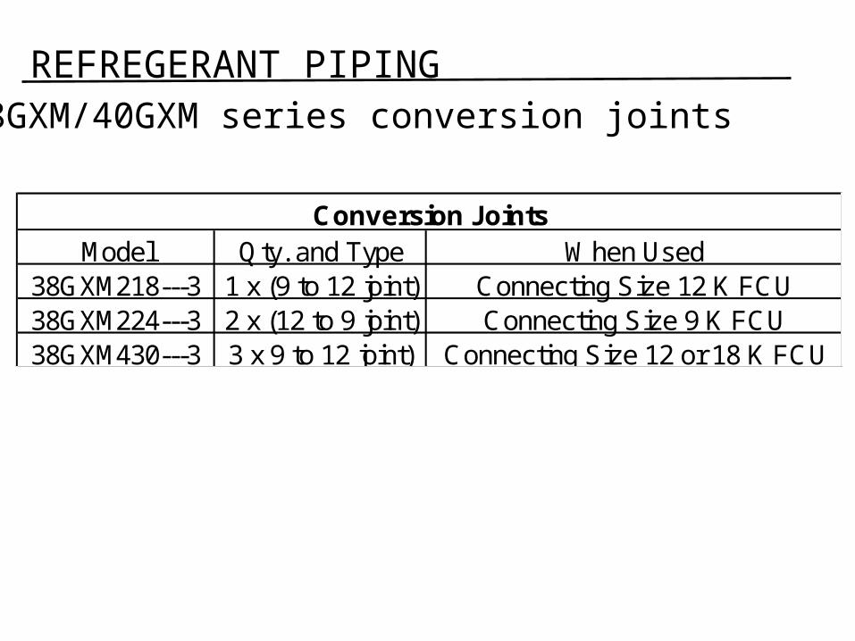
REFREGERANT PIPING 38GXM/40GXM series conversion joints
Model Qty. and Type When Used38GXM218---3 1 x (9 to 12 joint) Connecting Size 12 K FCU38GXM224---3 2 x (12 to 9 joint) Connecting Size 9 K FCU38GXM430---3 3 x 9 to 12 joint) Connecting Size 12 or 18 K FCU
Conversion Joints
Back to main menu
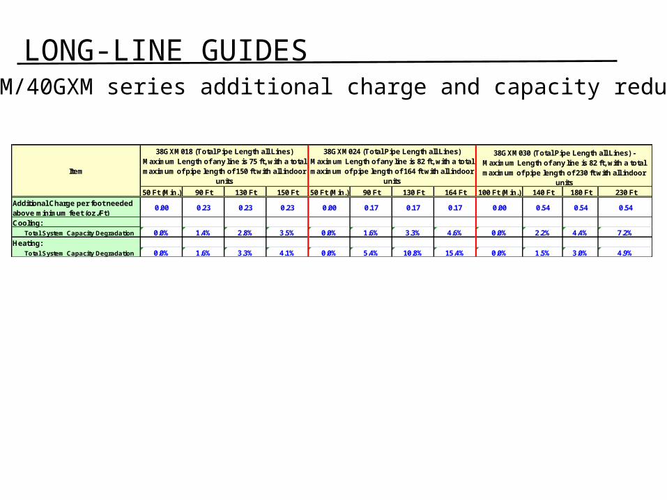
LONG-LINE GUIDES 38GXM/40GXM series additional charge and capacity reduction
50 Ft (Min.) 90 Ft 130 Ft 150 Ft 50 Ft (Min.) 90 Ft 130 Ft 164 Ft 100 Ft (Min.) 140 Ft 180 Ft 230 Ft
Additional Charge per foot needed above minimum feet (oz./Ft)
0.00 0.23 0.23 0.23 0.00 0.17 0.17 0.17 0.00 0.54 0.54 0.54
Cooling:Total System Capacity Degradation 0.0% 1.4% 2.8% 3.5% 0.0% 1.6% 3.3% 4.6% 0.0% 2.2% 4.4% 7.2%
Heating:Total System Capacity Degradation 0.0% 1.6% 3.3% 4.1% 0.0% 5.4% 10.8% 15.4% 0.0% 1.5% 3.0% 4.9%
38GXM018 (Total Pipe Length all Lines) Maximum Length of any line is 75 ft, with a total maximum of pipe length of 150 ft with all indoor
units
38GXM024 (Total Pipe Length all Lines) Maximum Length of any line is 82 ft, with a total maximum of pipe length of 164 ft with all indoor
units
38GXM030 (Total Pipe Length all Lines) - Maximum Length of any line is 82 ft, with a total maximum of pipe length of 230 ft with all indoor
units
Item
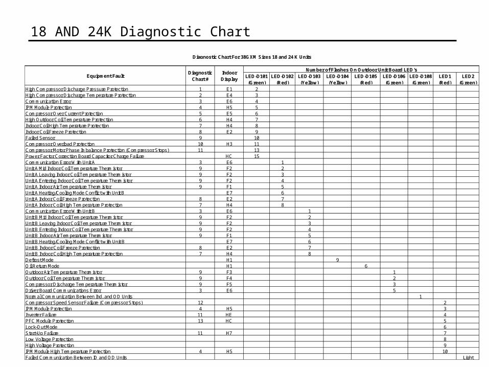
18 AND 24K Diagnostic Chart
LED-D101 (Green)
LED-D102 (Red)
LED-D103 (Yellow)
LED-D104 (Yellow)
LED-D105 (Red)
LED-D106 (Green)
LED-D108 (Green)
LED1 (Red)
LED2 (Green)
High Compressor Discharge Pressure Protection 1 E1 2High Compressor Discharge Temperature Protection 2 E4 3Communication Error 3 E6 4IPM Module Protection 4 H5 5Compressor Over Current Protection 5 E5 6High Outdoor Coil Temperature Protection 6 H4 7Indoor Coil High Temperature Protection 7 H4 8Indoor Coil Freeze Protection 8 E2 9Failed Sensor 9 10Compressor Overload Protection 10 H3 11Compressor Motor Phase Imbalance Protection (Compressor Stops) 11 13Power Factor Correction Board Capacitor Charge Failure HC 15Communication Error With Unit A 3 E6 1Unit A Mid Indoor Coil Temperature Thermistor 9 F2 2Unit A Leaving Indoor Coil Temperature Thermistor 9 F2 3Unit A Entering Indoor Coil Temperature Thermistor 9 F2 4Unit A Indoor Air Temperature Thermistor 9 F1 5Unit A Heating/Cooling Mode Conflict with Unit B E7 6Unit A Indoor Coil Freeze Protection 8 E2 7Unit A Indoor Coil High Temperature Protection 7 H4 8Communication Error With Unit B 3 E6 1Unit B Mid Indoor Coil Temperature Thermistor 9 F2 2Unit B Leaving Indoor Coil Temperature Thermistor 9 F2 3Unit B Entering Indoor Coil Temperature Thermistor 9 F2 4Unit B Indoor Air Temperature Thermistor 9 F1 5Unit B Heating/Cooling Mode Conflict with Unit B E7 6Unit B Indoor Coil Freeze Protection 8 E2 7Unit B Indoor Coil High Temperature Protection 7 H4 8Defrost Mode H1 9Oil Return Mode H1 6Outdoor Air Temperature Thermistor 9 F3 1Outdoor Coil Temperature Thermistor 9 F4 2Compressor Discharge Temperature Thermistor 9 F5 3Driver Board Communications Error 3 E6 5Normal Communication Between Ind. and OD Units 1Compressor Speed Sensor Failure (Compressor Stops) 12 2IPM Module Protection 4 H5 3Inverter Failure 11 HE 4PFC Module Protection 13 HC 5Lock-Out Mode 6Start-Up Failure 11 H7 7Low Voltage Protection 8High Voltage Protection 9IPM Module High Temperature Protection 4 H5 10Failed Communication Between ID and OD Units Light
Number of Flashes On Outdoor Unit Board LED'sEquipment Fault
Diagnostic Chart For 38GXM Sizes 18 and 24 K Units
Diagnostic Chart #
Indoor Display
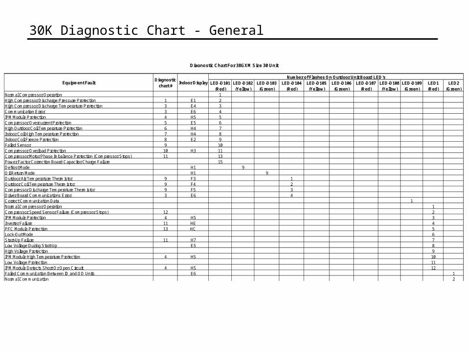
30K Diagnostic Chart - General
LED-D101 (Red)
LED-D102 (Yellow)
LED-D103 (Green)
LED-D104 (Red)
LED-D105 (Yellow)
LED-D106 (Green)
LED-D107 (Red)
LED-D108 (Yellow)
LED-D109 (Green)
LED1 (Red)
LED2 (Green)
Normal Compressor Operation 1High Compressor Discharge Pressure Protection 1 E1 2High Compressor Discharge Temperature Protection 3 E4 3Communication Error 3 E6 4IPM Module Protection 4 H5 5Compressor Overcurrent Protection 5 E5 6High Outdoor Coil Temperature Protection 6 H4 7Indoor Coil High Temperature Protection 7 H4 8Indoor Coil Freeze Protection 8 E2 9Failed Sensor 9 10Compressor Overload Protection 10 H3 11Compressor Motor Phase Imbalance Protection (Compressor Stops) 11 13Power Factor Correction Board Capacitor Charge Failure 15Defrost Mode H1 9Oil Return Mode H1 9Outdoor Air Temperature Thermistor 9 F3 1Outdoor Coil Temperature Thermistor 9 F4 2Compressor Discharge Temperature Thermistor 9 F5 3Driver Board Communications Error 3 E6 4Correct Communication Data 1Normal Compressor Operation 1Compressor Speed Sensor Failure (Compressor Stops) 12 2IPM Module Protection 4 H5 3Inverter Failure 11 HE 4PFC Module Protection 13 HC 5Lock-Out Mode 6Start-Up Failure 11 H7 7Low Voltage During Start-Up E5 8High Voltage Protection 9IPM Module High Temperature Protection 4 H5 10Low Voltage Protection 11IPM Module Detects Short Or Open Circuit 4 H5 12Failed Communication Between ID and OD Units E6 1Normal Communication 2
Diagnostic Chart For 38GXM Size 30 Unit
Equipment FaultDiagnostic
chart #
Number of Flashes On Outdoor Unit Board LED'sIndoor Display
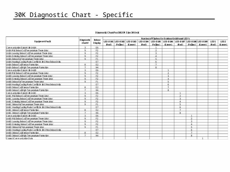
30K Diagnostic Chart - Specific
LED-D101 (Red)
LED-D102 (Yellow)
LED-D103 (Green)
LED-D104 (Red)
LED-D105 (Yellow)
LED-D106 (Green)
LED-D107 (Red)
LED-D108 (Yellow)
LED-D109 (Green)
LED1 (Red)
LED2 (Green)
Communication Error With Unit A 3 E6 1Unit A Mid Indoor Coil Temperature Thermistor 9 F2 2Unit A Leaving Indoor Coil Temperature Thermistor 9 F2 3Unit A Entering Indoor Coil Temperature Thermistor 9 F2 4Unit A Indoor Air Temperature Thermistor 9 F1 5Unit A Heating/Cooling Mode Conflict With Other Indoor Units E7 6Unit A Indoor Coil Freeze Protection 8 E2 7Unit A Indoor Coil High Temperature Protection 7 H4 8Communication Error With Unit B 3 E6 1Unit B Mid Indoor Coil Temperature Thermistor 9 F2 2Unit B Leaving Indoor Coil Temperature Thermistor 9 F2 3Unit B Entering Indoor Coil Temperature Thermistor 9 F2 4Unit B Indoor Air Temperature Thermistor 9 F1 5Unit B Heating/Cooling Mode Conflict With Other Indoor Units E7 6Unit B Indoor Coil Freeze Protection 8 E2 7Unit B Indoor Coil High Temperature Protection 7 H4 8Communication Error With Unit C 3 E6 1Unit C Mid Indoor Coil Temperature Thermistor 9 F2 2Unit C Leaving Indoor Coil Temperature Thermistor 9 F2 3Unit C Entering Indoor Coil Temperature Thermistor 9 F2 4Unit C Indoor Air Temperature Thermistor 9 F1 5Unit C Heating/Cooling Mode Conflict With Other Indoor Units E7 6Unit C Indoor Coil Freeze Protection 8 E2 7Unit C Indoor Coil High Temperature Protection 7 H4 8Communication Error With Unit D 3 E6 1Unit D Mid Indoor Coil Temperature Thermistor 9 F2 2Unit D Leaving Indoor Coil Temperature Thermistor 9 F2 3Unit D Entering Indoor Coil Temperature Thermistor 9 F2 4Unit D Indoor Air Temperature Thermistor 9 F1 5Unit D Heating/Cooling Mode Conflict With Other Indoor Units E7 6Unit D Indoor Coil Freeze Protection 8 E2 7Unit D Indoor Coil High Temperature Protection 7 H4 8Correct Communication Data 1
Diagnostic Chart For 38GXM Size 30 Unit
Equipment FaultDiagnostic
chart #
Number of Flashes On Outdoor Unit Board LED'sIndoor Display
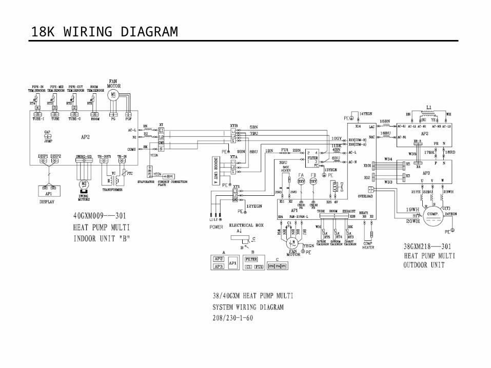
18K WIRING DIAGRAM
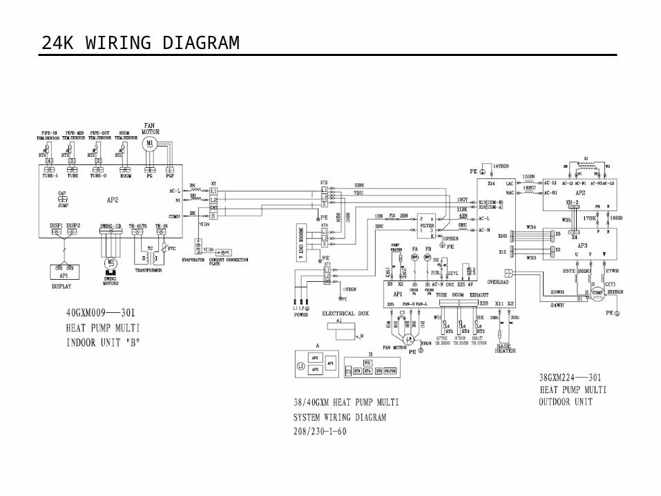
24K WIRING DIAGRAM
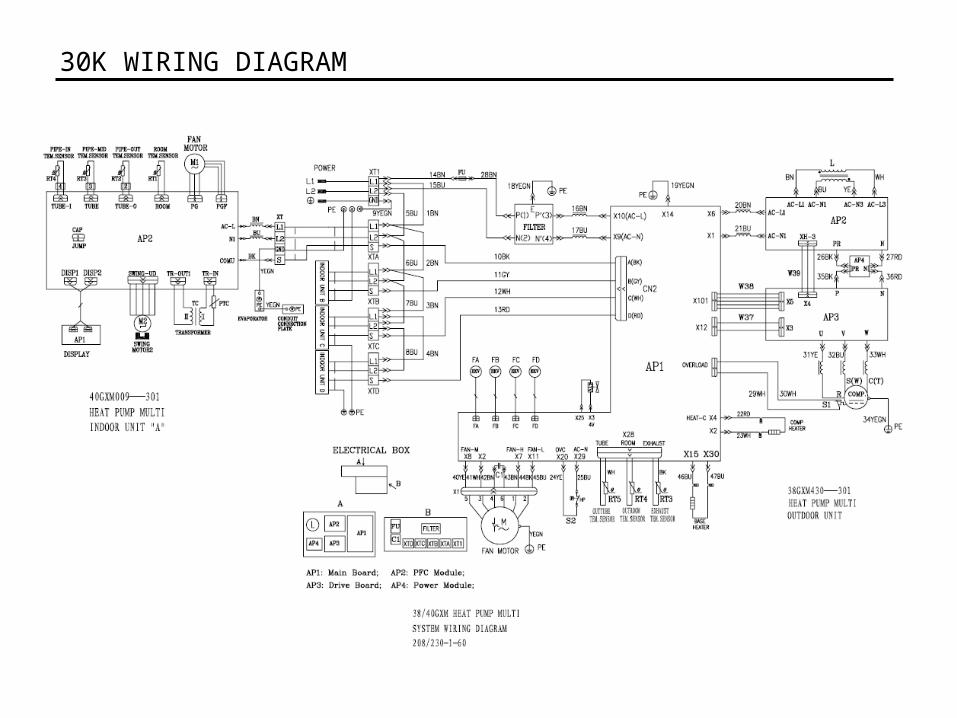
30K WIRING DIAGRAM

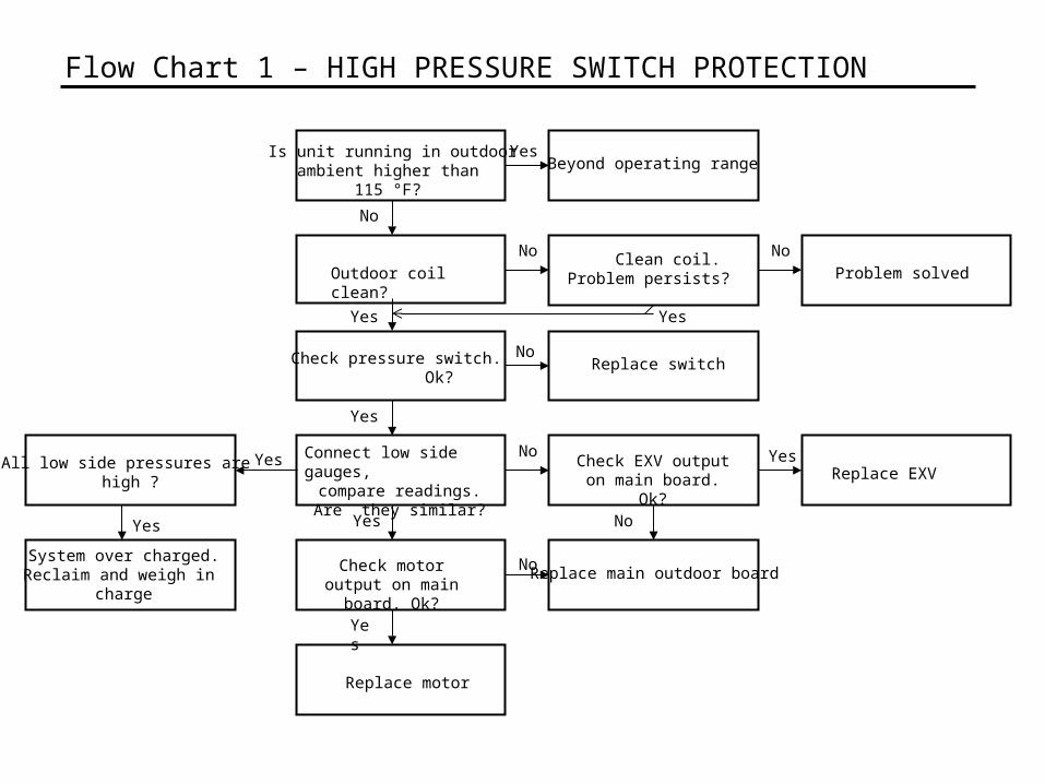
Flow Chart 1 – HIGH PRESSURE SWITCH PROTECTION
Check pressure switch. Ok?
Replace motor
No
No
Yes
Yes
Yes
Connect low side gauges,compare readings. Are
they similar?
Replace switch
Check EXV output on main board. Ok?
Replace main outdoor board
No
Is unit running in outdoorambient higher than
115 °F?
Beyond operating range
Outdoor coil clean? Clean coil.Problem persists? Problem solved
Yes
No No
No
YesReplace EXV
Check motor output on main board. Ok?
No
All low side pressures are high ?
Yes
System over charged.Reclaim and weigh in
charge
Yes Yes
Yes
Flow Chart 1 – HIGH PRESSURE SWITCH PROTECTION
Check pressure switch. Ok?
Replace motor
No
No
Yes
Yes
Yes
Connect low side gauges,compare readings. Are
they similar?
Replace switch
Check EXV output on main board. Ok?
Replace main outdoor board
No
Is unit running in outdoorambient higher than
115 °F?
Beyond operating range
Outdoor coil clean? Clean coil.Problem persists? Problem solved
Yes
No No
No
YesReplace EXV
Check motor output on main board. Ok?
No
All low side pressures are high ?
Yes
System over charged.Reclaim and weigh in
charge
Yes
Yes Yes
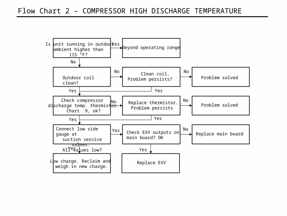
Flow Chart 2 – COMPRESSOR HIGH DISCHARGE TEMPERATURE
Is unit running in outdoorambient higher than
115 °F?
Beyond operating range
Outdoor coil clean? Clean coil.Problem persists? Problem solved
Check compressor discharge temp. thermistor.
Chart 9, ok?
Replace thermistor. Problem persists
Problem solved
Check EXV outputs on main board? OK
Yes
No
Yes
No No
No
Yes
No
Yes
Yes
Yes
Yes
Connect low side gauge atsuction service valves.
All values low?
NoReplace main board
Low charge. Reclaim and weigh in new charge.
Replace EXV
Yes
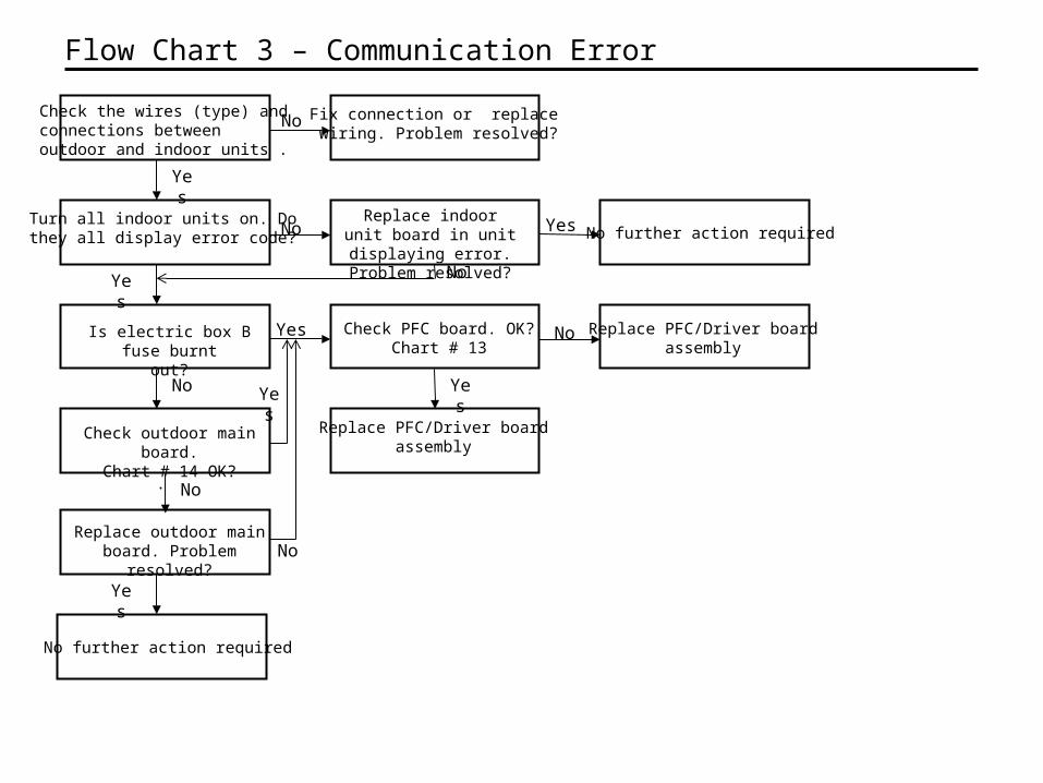
Turn all indoor units on. Dothey all display error code?
.
Replace indoor unit board in unit displaying
error. Problem resolved?
No
Yes
Flow Chart 3 – Communication Error
Is electric box B fuse burntout?
Yes
Check the wires (type) and connections betweenoutdoor and indoor units .
No
Fix connection or replace wiring. Problem resolved?
No
Yes
Check outdoor main board.Chart # 14 OK?
Yes
No
No further action requiredYes
No
No
Replace outdoor main board. Problem resolved?
Yes
No further action required
Check PFC board. OK?Chart # 13
Replace PFC/Driver board assembly
Replace PFC/Driver board assembly
Yes
No
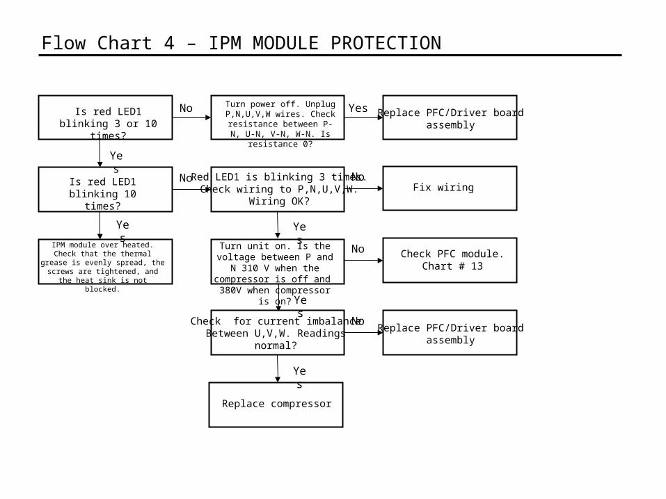
Is red LED1 blinking 3 or 10 times?
Turn power off. Unplug P,N,U,V,W wires. Check
resistance between P-N, U-N, V-N, W-N. Is resistance 0?
No
Yes
Flow Chart 4 – IPM MODULE PROTECTION
IPM module over heated.Check that the thermal grease is
evenly spread, the screws are tightened, and the heat sink is not
blocked.
Yes
No Red LED1 is blinking 3 times.Check wiring to P,N,U,V,W.
Wiring OK?
Yes
Turn unit on. Is the voltage between P and N 310 V when
the compressor is off and 380V when compressor is on?
Yes Replace PFC/Driver board assembly
Is red LED1 blinking 10 times?
NoFix wiring
Yes
No Check PFC module.Chart # 13
Check for current imbalanceBetween U,V,W. Readings
normal?
NoReplace PFC/Driver board
assembly
Yes
Replace compressor

Flow Chart 5 – Compressor Over Current Protection
Is unit running in outdoorambient higher than
115 °F?
Beyond operating range
Outdoor coil clean? Clean coil.Problem persists? Problem solved
Check motor output onoutdoor board. Ok?
Connect low side gauge atsuction service valve.
Suction pressure normal?
Check compressor. Referto Chart # 15
Check compressor. Referto Chart #15
High suction?
Unit is overcharged. Reclaim charge and weigh in correct charge.
Yes
No
Yes Yes
No
No
No No
Yes
No
Yes
Yes
Outdoor motor ok? Replace motor
Yes
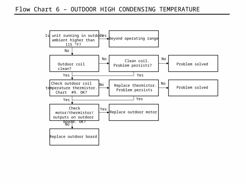
Flow Chart 6 – OUTDOOR HIGH CONDENSING TEMPERATURE
Is unit running in outdoorambient higher than
115 °F?
Beyond operating range
Outdoor coil clean? Clean coil.Problem persists? Problem solved
Check outdoor coiltemperature thermistor.
Chart #9. OK?
Check motor/thermistor/ outputs on outdoor board.
OK?
Replace outdoor board
Replace thermistor. Problem persists
Problem solved
Replace outdoor motor
Yes
No
Yes
No No
No
Yes
No
Yes
Yes
Yes
No
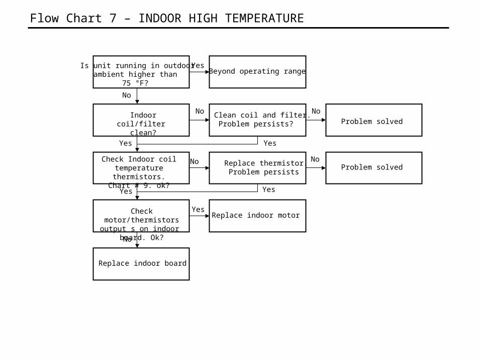
Flow Chart 7 – INDOOR HIGH TEMPERATURE
Is unit running in outdoorambient higher than
75 °F?
Beyond operating range
Indoor coil/filter clean?
Clean coil and filter.Problem persists? Problem solved
Check Indoor coiltemperature thermistors.
Chart # 9. ok?
Check motor/thermistors output s on indoor board.
Ok?
Replace indoor board
Replace thermistor. Problem persists
Problem solved
Replace indoor motor
Yes
No
Yes
No No
No
Yes
No
Yes
Yes
Yes
No
.
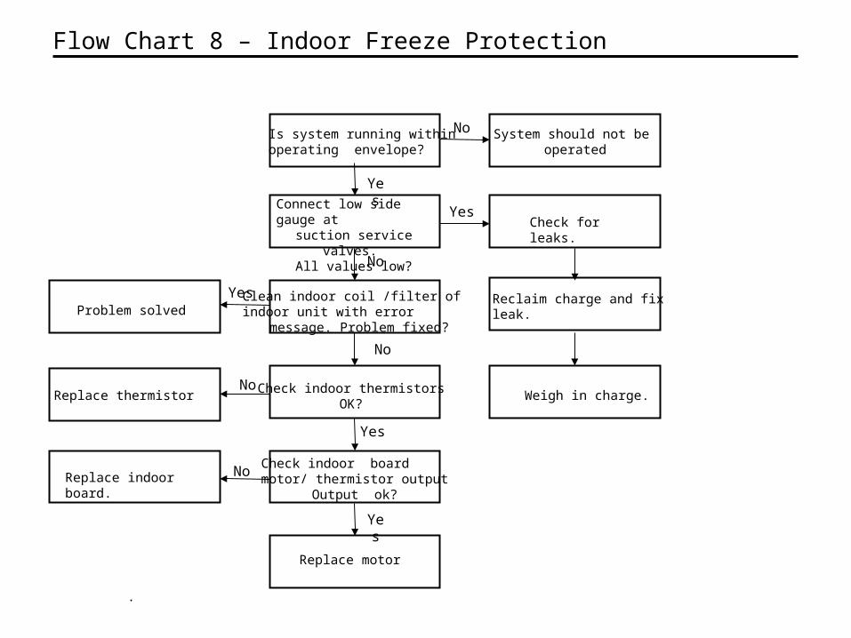
Flow Chart 8 – Indoor Freeze Protection
No
Yes
Replace motor
Connect low side gauge atsuction service valves.
All values low?
Yes
No
Check for leaks.
Reclaim charge and fixleak.
Weigh in charge.
No
Clean indoor coil /filter of indoor unit with error message. Problem fixed?
Yes
No
Problem solved
Check indoor boardmotor/ thermistor output
Output ok?Replace indoor board.
Is system running within operating envelope?
System should not be operated
No
Yes
Yes
Check indoor thermistorsOK?
Replace thermistor
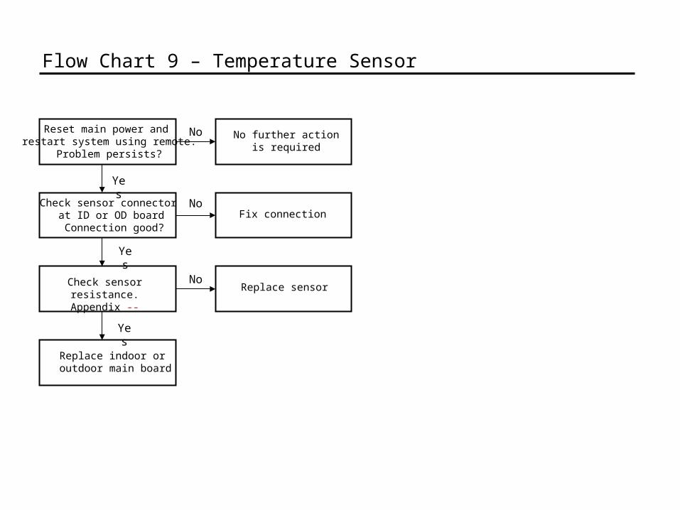
Reset main power and restart system using remote.
Problem persists?
Check sensor resistance.Appendix --
No further action is required
No
Yes
Flow Chart 9 – Temperature Sensor
Yes
Check sensor connector at ID or OD board Connection good?
NoFix connection
Yes
NoReplace sensor
Replace indoor oroutdoor main board
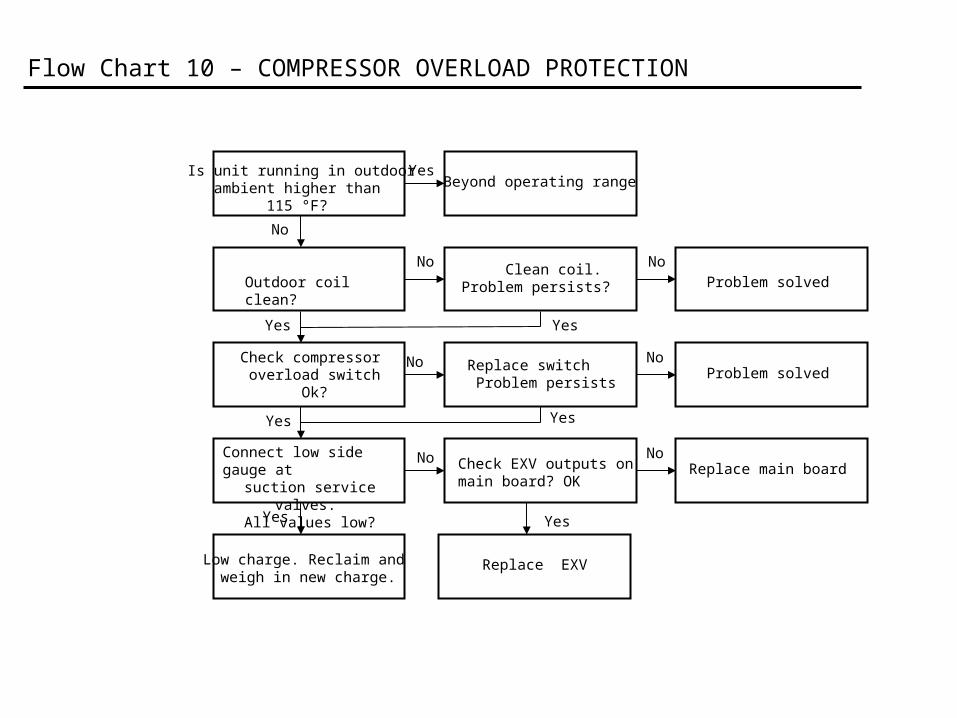
Flow Chart 10 – COMPRESSOR OVERLOAD PROTECTION
Is unit running in outdoorambient higher than
115 °F?
Beyond operating range
Outdoor coil clean? Clean coil.Problem persists? Problem solved
Check compressor overload switch
Ok?
Replace switch Problem persists
Problem solved
Check EXV outputs on main board? OK
Yes
No
No
No No
No
Yes
No
Yes
Yes
Yes
Yes
Connect low side gauge atsuction service valves.
All values low?
NoReplace main board
Yes
Low charge. Reclaim and weigh in new charge.
Replace EXV
Check Compressor Replace CompressorNo
Yes
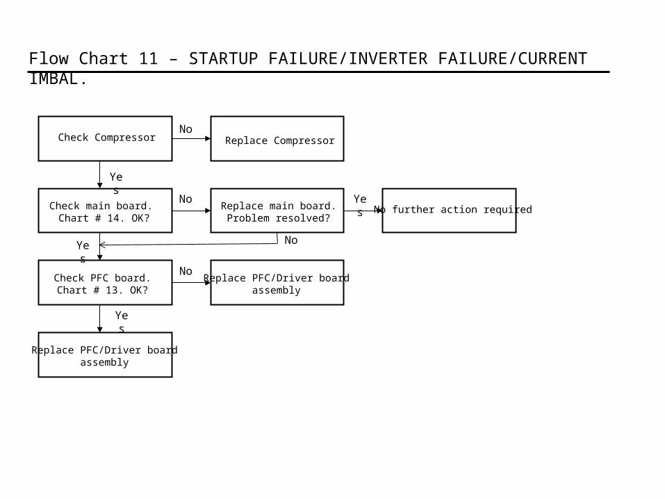
Flow Chart 11 – STARTUP FAILURE/INVERTER FAILURE/CURRENT IMBAL.
Check PFC board.Chart # 13. OK?
Yes
Check main board. Chart # 14. OK?
NoReplace main board.Problem resolved?
Yes
NoReplace PFC/Driver board
assembly
No further action requiredYes
No
Replace PFC/Driver board assembly
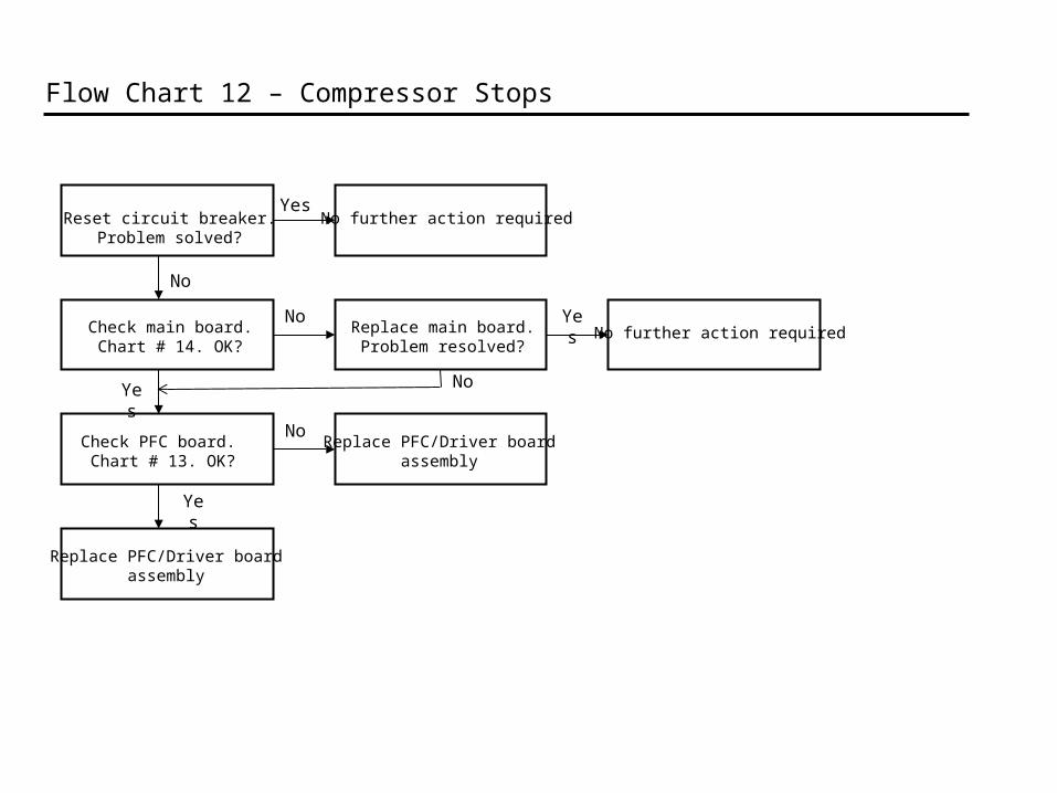
Reset circuit breaker.Problem solved?
Yes
Yes
Flow Chart 12 – Compressor Stops
Check PFC board. Chart # 13. OK?
Check main board. Chart # 14. OK?
NoReplace main board.Problem resolved?
Yes
NoReplace PFC/Driver board
assembly
No further action requiredYes
No
Replace PFC/Driver board assembly
No further action required
No
.
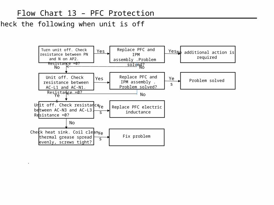
Flow Chart 13 – PFC Protection
Unit off. Check resistance between AC-L1 and AC-
N1. Resistance =0?
Turn unit off. Check resistance between PN and N on AP2. Resistance =0?
Replace PFC and IPM assembly .Problem
solved?
Yes
No
Yes
Replace PFC electric inductance
Yes
Unit off. Check resistance between AC-N3 and AC-L3.Resistance =0?
No
Check heat sink. Coil clean,thermal grease spread evenly, screws tight?
No additional action is required
Problem solved
Yes
No
No
Yes
Yes
Replace PFC and IPM assembly . Problem
solved?
Fix problemYes
Check the following when unit is off
.
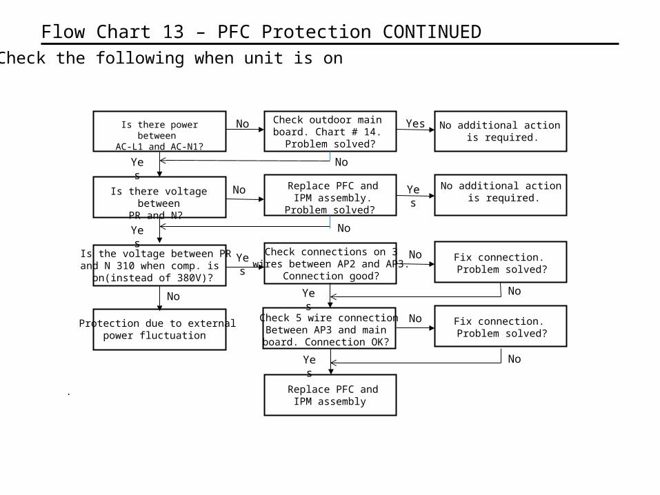
Flow Chart 13 – PFC Protection CONTINUED
Is there voltage betweenPR and N?
Is there power between AC-L1 and AC-N1?
Check outdoor main board. Chart # 14. Problem solved?
No
Yes
No
Check connections on 3wires between AP2 and AP3.
Connection good?
Yes
Is the voltage between PRand N 310 when comp. is
on(instead of 380V)?
No
Protection due to externalpower fluctuation
No additional action is required.
Yes
No
No
Yes
Yes
Replace PFC and IPM assembly. Problem
solved?
Check 5 wire connectionBetween AP3 and main board. Connection OK?
Check the following when unit is on
Fix connection. Problem solved?
No
Yes
Fix connection. Problem solved?
No
Yes
Replace PFC and IPM assembly
No
No
No additional action is required.
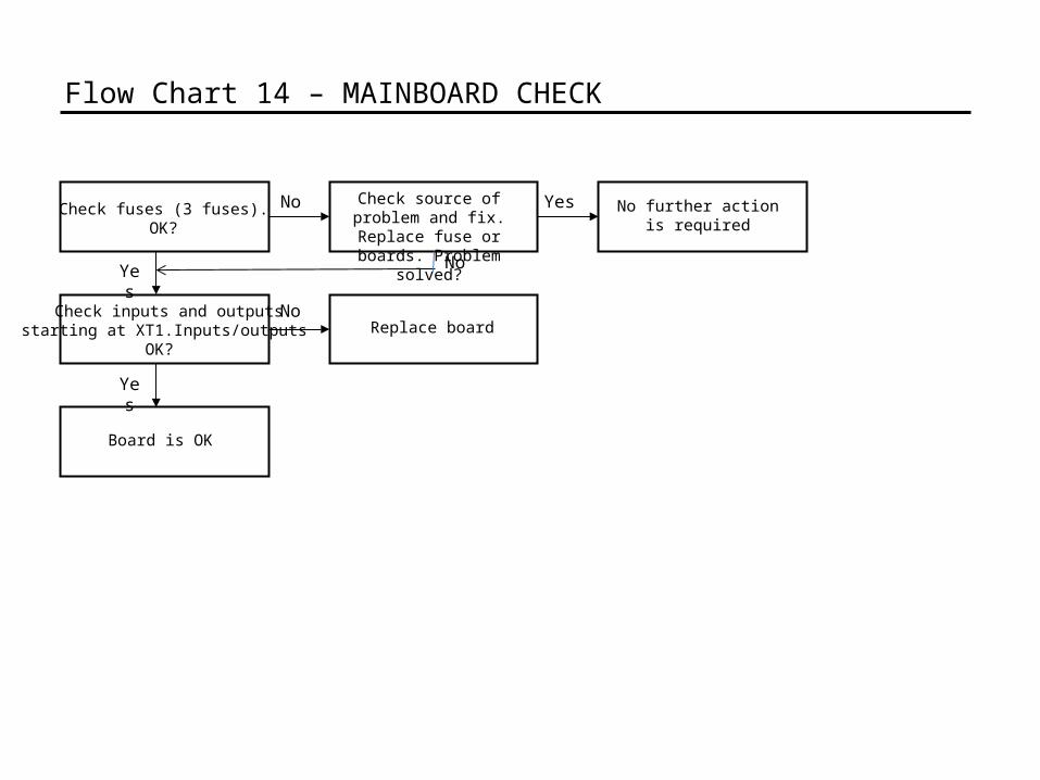
Check fuses (3 fuses).OK?
Check source of problem and fix. Replace fuse or boards. Problem solved?
No
Yes
Flow Chart 14 – MAINBOARD CHECK
Board is OK
Yes
Check inputs and outputsstarting at XT1.Inputs/outputs
OK?
NoReplace board
No further action is required
Yes
No
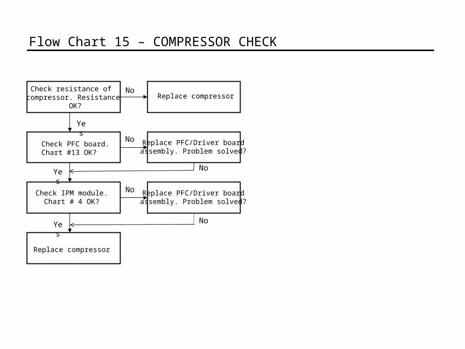
Check resistance of compressor. Resistance
OK?
Replace compressor
Replace compressorNo
Yes
Flow Chart 15 – COMPRESSOR CHECK
Check IPM module.Chart # 4 OK?
Yes
Check PFC board.Chart #13 OK?
No
Yes
No
Replace PFC/Driver board assembly. Problem solved?
Replace PFC/Driver board assembly. Problem solved?
No
No
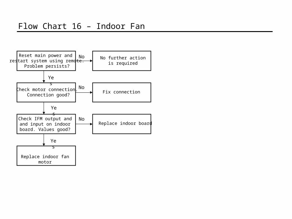
Reset main power and restart system using remote.
Problem persists?
Replace indoor fan motor
No further action is required
No
Yes
Flow Chart 16 – Indoor Fan
Check IFM output and and input on indoor
board. Values good?
Yes
Check motor connection. Connection good?
NoFix connection
Yes
NoReplace indoor board
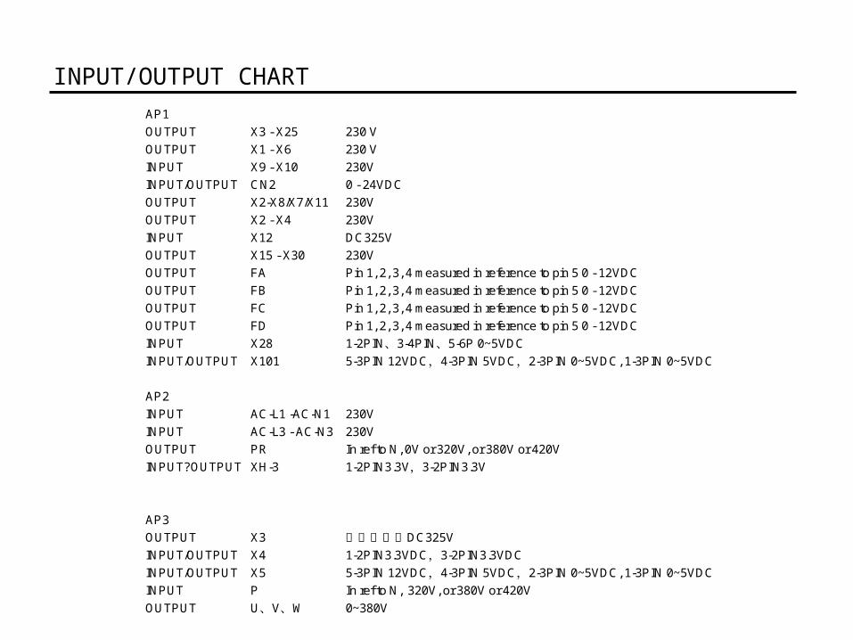
INPUT/OUTPUT CHART AP1OUTPUT X3 - X25 230 VOUTPUT X1 - X6 230 VINPUT X9 - X10 230VINPUT/OUTPUT CN2 0 - 24VDCOUTPUT X2-X8/X7/X11 230VOUTPUT X2 - X4 230VINPUT X12 DC325VOUTPUT X15 - X30 230VOUTPUT FA Pin 1, 2, 3, 4 measured in reference to pin 5 0 - 12VDCOUTPUT FB Pin 1, 2, 3, 4 measured in reference to pin 5 0 - 12VDCOUTPUT FC Pin 1, 2, 3, 4 measured in reference to pin 5 0 - 12VDCOUTPUT FD Pin 1, 2, 3, 4 measured in reference to pin 5 0 - 12VDCINPUT X28 1-2PIN 3-4PIN 5-6P 0~5VDC、 、INPUT/OUTPUT X101 5-3PIN 12VDC 4-3PIN 5VDC 2-3PIN 0~5VDC, 1-3PIN 0~5VDC, ,
AP2INPUT AC-L1 -AC-N1 230VINPUT AC-L3 - AC-N3 230VOUTPUT PR In ref to N, 0V or 320V, or 380V or 420VINPUT?OUTPUT XH-3 1-2PIN3.3V 3-2PIN3.3V,
AP3OUTPUT X3 DC325V两端之间约INPUT/OUTPUT X4 1-2PIN3.3VDC 3-2PIN3.3VDC,INPUT/OUTPUT X5 5-3PIN 12VDC 4-3PIN 5VDC 2-3PIN 0~5VDC, 1-3PIN 0~5VDC, ,INPUT P In ref to N, 320V, or 380V or 420VOUTPUT U V W、 、 0~380V
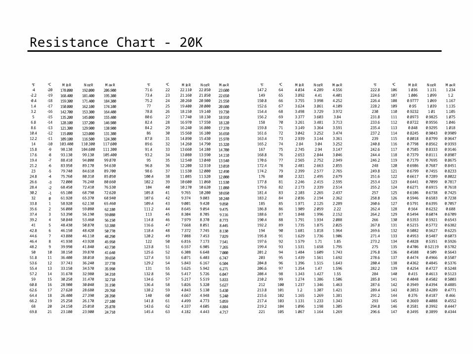
Resistance Chart - 20K
°F °C Min R Nor R Max R °F °C Min R Nor R Max R °F °C Min R Nor R Max R °F °C Min R Nor R Max R-4 -20 178.000 192.000 206.900 71.6 22 22.110 22.850 23.600 147.2 64 4.034 4.289 4.556 222.8 106 1.036 1.131 1.234
-2.2 -19 168.400 181.400 195.300 73.4 23 21.160 21.850 22.650 149 65 3.892 4.41 4.401 224.6 107 1.006 1.099 1.2-0.4 -18 159.300 171.400 184.300 75.2 24 20.260 20.900 21.550 150.8 66 3.755 3.998 4.252 226.4 108 0.9777 1.069 1.1671.4 -17 150.800 162.100 174.100 77 25 19.400 20.000 20.600 152.6 67 3.624 3.861 4.109 228.2 109 0.95 1.039 1.1353.2 -16 142.700 153.300 164.400 78.8 26 18.150 19.140 19.730 154.4 68 3.498 3.729 3.972 230 110 0.9232 1.01 1.1055 -15 135.200 145.000 155.400 80.6 27 17.740 18.130 18.910 156.2 69 3.377 3.603 3.84 231.8 111 0.8973 0.9825 1.075
6.8 -14 128.100 137.200 146.900 82.4 28 16.970 17.550 18.120 158 70 3.261 3.481 3.713 233.6 112 0.8722 0.9556 1.0468.6 -13 121.300 129.900 138.900 84.2 29 16.240 16.800 17.370 159.8 71 3.149 3.364 3.591 235.4 113 0.848 0.9295 1.01810.4 -12 115.000 123.000 131.300 86 30 15.560 16.100 16.650 161.6 72 3.042 3.252 3.474 237.2 114 0.8245 0.9043 0.990912.2 -11 109.100 116.500 124.300 87.8 31 14.890 15.430 15.970 163.4 73 2.939 3.144 3.361 239 115 0.8018 0.8799 0.964714 -10 103.400 110.300 117.600 89.6 32 14.260 14.790 15.320 165.2 74 2.84 3.04 3.252 240.8 116 0.7798 0.8562 0.9393
15.8 -9 98.130 104.600 111.300 91.4 33 13.660 14.180 14.700 167 75 2.745 2.94 3.147 242.6 117 0.7585 0.8333 0.914617.6 -8 93.130 99.130 105.400 93.2 34 13.080 13.590 14.110 168.8 76 2.653 2.844 3.046 244.4 118 0.7379 0.8111 0.890719.4 -7 88.410 94.000 99.870 95 35 12.540 13.040 13.540 170.6 77 2.565 2.752 2.949 246.2 119 0.7179 0.7695 0.867521.2 -6 83.950 89.170 94.630 96.8 36 12.200 12.510 13.010 172.4 78 2.481 2.663 2.855 248 120 0.6986 0.7687 0.845123 -5 79.740 84.610 89.700 98.6 37 11.530 12.000 12.490 174.2 79 2.399 2.577 2.765 249.8 121 0.6799 0.7455 0.8233
24.8 -4 75.760 80.310 85.050 100.4 38 11.085 11.520 12.000 176 80 2.321 2.495 2.679 251.6 122 0.6617 0.7289 0.802226.6 -3 72.000 76.240 80.660 102.2 39 10.600 11.060 11.530 177.8 81 2.246 2.415 2.595 253.4 123 0.6441 0.7099 0.781728.4 -2 68.450 72.410 76.530 104 40 10.170 10.620 11.080 179.6 82 2.173 2.339 2.514 255.2 124 0.6271 0.6915 0.761830.2 -1 65.100 68.790 72.620 105.8 41 9.765 10.200 10.650 181.4 83 2.103 2.265 2.437 257 125 0.6106 0.6738 0.742532 0 61.920 65.370 68.940 107.6 42 9.374 9.803 10.240 183.2 84 2.036 2.194 2.362 258.8 126 0.5946 0.6583 0.7238
33.8 1 58.920 62.130 65.460 109.4 43 9.001 9.420 9.850 185 85 1.971 2.125 2.289 260.6 127 0.5791 0.6395 0.705735.6 2 56.080 59.080 62.180 111.2 44 8.645 9.054 9.475 186.8 86 1.909 2.059 2.22 262.4 128 0.564 0.6232 0.68837.4 3 53.390 56.190 59.080 113 45 8.304 8.705 9.116 188.6 87 1.848 1.996 2.152 264.2 129 0.5494 0.6074 0.670939.2 4 50.840 53.460 56.150 114.8 46 7.979 8.370 8.773 190.4 88 1.791 1.934 2.088 266 130 0.5353 0.5921 0.654341 5 48.430 50.870 53.380 116.6 47 7.668 8.051 8.445 192.2 89 1.735 1.875 2.025 267.8 131 0.5215 0.5772 0.6382
42.8 6 46.150 48.420 50.770 118.4 48 7.372 7.745 8.130 194 90 1.681 1.818 1.964 269.6 132 0.5082 0.5627 0.622544.6 7 43.880 46.110 48.290 120.2 49 7.088 7.453 7.829 195.8 91 1.629 1.736 1.906 271.4 133 0.4953 0.5487 0.607346.4 8 41.930 43.920 45.950 122 50 6.816 7.173 7.541 197.6 92 1.579 1.71 1.85 273.2 134 0.4828 0.5351 0.592648.2 9 39.990 41.840 43.730 123.8 51 6.557 6.905 7.265 199.4 93 1.531 1.658 1.795 275 135 0.4706 0.52119 0.578250 10 38.150 39.870 41.640 125.6 52 6.308 6.648 7.000 201.2 94 1.484 1.609 1.743 276.8 136 0.4588 0.509 0.5643
51.8 11 36.400 38.010 39.650 127.4 53 6.071 6.403 6.747 203 95 1.439 1.561 1.692 278.6 137 0.4474 0.4966 0.550753.6 12 37.743 36.240 37.770 129.2 54 5.843 6.167 6.504 204.8 96 1.396 1.515 1.643 280.4 138 0.4362 0.4845 0.537655.4 13 33.150 34.570 35.990 131 55 5.625 5.942 6.271 206.6 97 1.354 1.47 1.596 282.2 139 0.4254 0.4727 0.524857.2 14 31.670 32.980 34.310 132.8 56 5.417 5.726 6.047 208.4 98 1.343 1.427 1.55 284 140 0.415 0.4613 0.512359 15 30.250 31.470 32.710 134.6 57 5.217 5.519 5.833 210.2 99 1.274 1.386 1.506 285.8 141 0.4048 0.4502 0.5003
60.8 16 28.900 30.040 31.190 136.4 58 5.026 5.320 5.627 212 100 1.237 1.346 1.463 287.6 142 0.3949 0.4394 0.488562.6 17 27.620 28.680 29.760 138.2 59 4.843 5.130 5.430 213.8 101 1.2 1.307 1.421 289.4 143 0.3853 0.4289 0.477164.4 18 26.400 27.390 28.390 140 60 4.667 4.948 5.240 215.6 102 1.165 1.269 1.381 291.2 144 0.376 0.4187 0.46666.2 19 25.250 26.170 27.100 141.8 61 4.499 4.773 5.059 217.4 103 1.131 1.233 1.343 293 145 0.3669 0.4088 0.455268 20 24.150 25.010 25.870 143.6 62 4.337 4.605 4.884 219.2 104 1.096 1.198 1.305 294.8 146 0.3581 0.3992 0.4447
69.8 21 23.100 23.900 24.710 145.4 63 4.182 4.443 4.717 221 105 1.067 1.164 1.269 296.6 147 0.3495 0.3899 0.4344
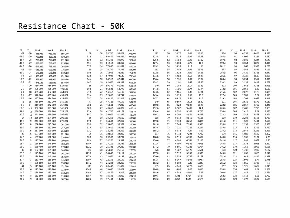
Resistance Chart - 50K
°F °C Min R Nor R Max R °F °C Min R Nor R Max R °F °C Min R Nor R Max R °F °C Min R Nor R Max R-22 -30 833.900 911.400 995.200 50 10 93.760 98.000 102.300 122 50 16.77 17.65 18.56 194 90 4.132 4.469 4.829
-20.2 -29 782.000 853.500 930.700 51.8 11 89.460 93.420 97.460 123.8 51 16.13 16.99 17.88 195.8 91 4.005 4.334 4.687-18.4 -28 733.800 799.800 871.100 53.6 12 85.380 89.070 92.840 125.6 52 15.52 16.36 17.22 197.6 92 3.882 4.204 4.549-16.6 -27 689.000 750.000 815.800 55.4 13 81.510 84.950 88.460 127.4 53 14.94 15.75 16.6 199.4 93 3.764 4.079 4.416-14.8 -26 647.300 703.800 764.500 57.2 14 77.840 81.050 84.320 129.2 54 14.38 15.17 16 201.2 94 3.65 3.958 4.287
-13 -25 608.500 660.800 716.900 59 15 74.350 77.350 80.390 131 55 13.84 14.62 15.43 203 95 3.541 3.841 4.163-11.2 -24 572.400 620.800 672.700 60.8 16 71.040 73.830 76.670 132.8 56 13.33 14.09 14.88 204.8 96 3.435 3.728 4.043-9.4 -23 538.800 580.600 631.600 62.6 17 67.900 70.500 73.140 134.6 57 12.83 13.58 14.05 206.6 97 3.332 3.619 3.928-7.6 -22 507.400 548.900 593.400 64.4 18 64.910 67.340 69.790 136.4 58 12.36 13.09 13.84 208.4 98 3.234 3.514 3.816-5.8 -21 478.100 516.600 557.400 66.2 19 62.070 64.330 66.620 138.2 59 11.91 12.62 13.35 210.2 99 3.138 3.413 3.708
-4 -20 450.700 486.500 524.600 68 20 59.370 61.480 63.610 140 60 11.48 12.17 12.89 212 100 3.046 3.315 3.603-2.2 -19 425.200 458.300 493.600 69.8 21 56.800 58.770 60.740 141.8 61 11.06 11.74 12.44 213.8 101 2.958 3.22 3.503-0.4 -18 401.200 432.000 464.800 71.6 22 54.360 56.190 58.030 143.6 62 10.66 11.32 12.01 215.6 102 2.872 3.129 3.4051.4 -17 378.900 407.400 437.800 73.4 23 52.030 53.740 55.450 145.4 63 10.28 10.93 11.6 217.4 103 2.789 3.04 3.3113.2 -16 357.900 384.500 412.600 75.2 24 49.820 51.410 53.000 147.2 64 9.917 10.54 11.2 219.2 104 2.709 2.955 3.219
5 -15 338.300 362.900 389.100 77 25 47.720 49.190 50.670 149 65 9.567 10.18 10.82 221 105 2.632 2.872 3.1316.8 -14 319.800 342.800 367.000 78.8 26 45.630 47.080 48.540 150.8 66 9.23 9.827 10.45 222.8 106 2.557 2.792 3.0468.6 -13 302.600 323.900 346.400 80.6 27 43.650 45.070 46.510 152.6 67 8.907 9.489 10.1 224.6 107 2.485 2.715 2.963
10.4 -12 286.300 306.200 327.100 82.4 28 41.760 43.160 44.570 154.4 68 8.597 9.165 9.763 226.4 108 2.416 2.64 2.88312.2 -11 271.100 289.600 309.000 84.2 29 39.960 41.340 42.730 156.2 69 8.299 8.854 9.438 228.2 109 2.348 2.568 2.806
14 -10 256.800 274.000 292.100 86 30 38.260 39.610 40.980 158 70 8.013 8.555 9.125 230 110 2.283 2.498 2.73115.8 -9 243.300 259.300 276.200 87.8 31 36.630 37.960 39.300 159.8 71 7.738 8.268 8.825 231.8 111 2.22 2.431 2.65917.6 -8 230.700 245.600 261.200 89.6 32 35.080 36.380 37.700 161.6 72 7.745 7.991 8.536 233.6 112 2.159 2.365 2.58919.4 -7 218.800 232.600 247.200 91.4 33 33.610 34.880 36.180 163.4 73 7.221 7.726 8.257 235.4 113 2.1 2.302 2.52121.2 -6 207.500 220.500 234.000 93.2 34 32.200 33.450 34.720 165.2 74 6.978 7.47 7.99 237.2 114 2.044 2.241 2.455
23 -5 197.000 209.000 221.600 95 35 30.860 32.090 33.330 167 75 6.744 7.224 7.732 239 115 1.988 2.182 2.39224.8 -4 187.000 198.300 210.000 96.8 36 29.580 30.790 32.010 168.8 76 6.519 6.998 7.484 240.8 116 1.935 2.124 2.3326.6 -3 177.600 199.100 199.000 98.6 37 28.370 29.540 30.740 170.6 77 6.303 6.761 7.245 242.6 117 1.883 2.069 2.2728.4 -2 168.800 178.500 188.700 100.4 38 27.210 28.360 29.530 172.4 78 6.095 6.542 7.016 244.4 118 1.833 2.015 2.21230.2 -1 160.400 169.500 179.000 102.2 39 26.100 27.230 28.380 174.2 79 5.895 6.331 6.794 246.2 119 1.758 1.963 2.165
32 0 152.500 161.000 169.800 104 40 25.040 26.150 27.270 176 80 5.702 6.129 6.581 248 120 1.738 1.912 2.10233.8 1 145.100 153.000 161.200 105.8 41 24.040 25.110 26.220 177.8 81 5.517 5.933 6.376 249.8 121 1.693 1.863 2.04935.6 2 138.000 145.400 153.100 107.6 42 23.070 24.130 25.210 179.6 82 5.339 5.746 6.178 251.6 122 1.649 1.816 1.99837.4 3 131.400 138.300 145.400 109.4 43 22.150 23.190 24.240 181.4 83 5.167 5.565 5.987 253.4 123 1.606 1.77 1.94839.2 4 125.100 131.500 138.100 111.2 44 21.280 22.290 23.320 183.2 84 5.002 5.39 5.803 255.2 124 1.565 1.725 1.9
41 5 119.100 125.100 131.300 113 45 20.440 21.430 22.440 185 85 4.843 5.222 5.626 257 125 1.525 1.682 1.84542.8 6 113.500 119.100 124.800 114.8 46 19.640 20.600 21.590 186.8 86 4.69 5.06 5.455 258.8 126 1.487 1.64 1.80844.6 7 108.100 113.400 118.700 116.6 47 18.870 19.810 20.780 188.6 87 4.543 4.904 5.29 260.6 127 1.449 1.6 1.75646.4 8 103.100 108.000 113.000 118.4 48 18.140 19.060 20.010 190.4 88 4.401 4.754 5.131 262.4 128 1.413 1.56 1.72248.2 9 98.300 102.800 107.500 120.2 49 17.440 18.340 19.270 192.2 89 4.264 4.609 4.977 264.2 129 1.377 1.522 1.681