38999 Series 1 - PEI-Genesis · For standard applications, these connectors come with crimp style...
12
177 38999 Series Series I For Assistance in Europe – Please See the Back Cover For a Complete Listing of Our Branch Offices and Contact Numbers. • Specifications subject to change. 38999 Series 1 38999 Series MIL-DTL-38999 Series I connectors offer high density contact arrangements in a miniature circular shell. Originally designed for the especially demanding requirements of today’s high performance military and commercial aircraft, these connectors are finding their way into applications needing ex- tremely reliable interconnections. Series I features include total environmental sealing, wide operating temperature range (-65°C to 200°C), quick mating three-point bayonet coupling, 100% scoop proof shell de- sign, EMI-RFI shielding, and they are available in a rugged 500-hour salt spray plating. • High Performance Military Aircraft • Commercial Airlines • Communications Equipment • Armored Personnel Carriers & Tanks • Missiles • Shipboard • Medical Instrumentation • High Reliability Test Equipment Quick Mating A three-point bayonet coupling system is quick mating and also provides an audible and tactile “click,” along with visual verification of mated connectors via a sighting hole and high-visibility, bright blue painted bayonet pins. Shielded Interconnect The plugs feature high quality grounding springs that provide 360 degrees of EMI/RFI shielding protection. These springs ground the barrel of the plug to the inside wall of the receptacle with a wiping action that offers effective protection from reception or transmission of electronic noise. Many Contact Layouts and Styles Series I connectors come in a wide variety of contact sizes and layouts up to 128 contacts. Printed circuit board, fiber optic, thermocouple, and coax style contacts are avail- able for special applications. Utilizes High-Quality Military Contacts For standard applications, these connectors come with crimp style military contacts designed to resist bending, and provide reliable performance under the most rigorous conditions. Corrosion Resistant Available with cadmium-over-nickel plating, Series I connectors have met and passed the 500-hour military salt spray corrosion tests. Applications Features
Transcript of 38999 Series 1 - PEI-Genesis · For standard applications, these connectors come with crimp style...

177
38
99
9 Series
Series I
For Assistance in Europe – Please See the Back Cover For a Complete Listing of Our Branch Offices and Contact Numbers. • Specifications subject to change.
38999 Series 1 38
99
9 Series
MIL-DTL-38999 Series I connectors offer high density contact arrangements in a miniature circular shell. Originally designed for the especially demanding requirements of today’s high performance military and commercial aircraft, these connectors are finding their way into applications needing ex-tremely reliable interconnections. Series I features include total environmental sealing, wide operating temperature range (-65°C to 200°C), quick mating three-point bayonet coupling, 100% scoop proof shell de-
sign, EMI-RFI shielding, and they are available in a rugged 500-hour salt spray plating.
• High Performance Military Aircraft• Commercial Airlines• Communications Equipment• Armored Personnel Carriers & Tanks• Missiles
• Shipboard• Medical Instrumentation• High Reliability Test Equipment
Quick MatingA three-point bayonet coupling system is quick mating and also provides an audible and tactile “click,” along with visual verification of mated connectors via a sighting hole and high-visibility, bright blue painted bayonet pins.Shielded InterconnectThe plugs feature high quality grounding springs that provide 360 degrees of EMI/RFI shielding protection. These springs ground the barrel of the plug to the inside wall of the receptacle with a wiping action that offers effective protection from reception or transmission of electronic noise. Many Contact Layouts and StylesSeries I connectors come in a wide variety of contact sizes and layouts up to 128 contacts. Printed circuit board, fiber optic, thermocouple, and coax style contacts are avail-able for special applications.Utilizes High-Quality Military ContactsFor standard applications, these connectors come with crimp style military contacts designed to resist bending, and provide reliable performance under the most rigorous conditions.Corrosion ResistantAvailable with cadmium-over-nickel plating, Series I connectors have met and passed the 500-hour military salt spray corrosion tests.
Applications
Features

178
38
99
9 Series
Series I
In North America: Pricing Delivery: 800-642-8750 • Tech Support: 800-523-0727 • www.peigenesis.com • Specifications subject to change.
38
99
9 Series
Series I
38999 Series 1STEP 1
Select Shell StyleReceptacle or Plug
MS27466T
MS27656T
Receptacle
mates with
Standard Plug
MS27467T
t t t t
MS27468T
Front mount with rear accessory threads.
+Rear mount with rear accessory threads.
Jam Nut with rear accessory threads.
+
+ Most Popular
Heat Shrink Product CSB2 CSB3 CSB4 CSB5 BSB1 HBSB2 BSB2 BSB3 BSB4 BSB5 Expanded ID 0.70 1.06 1.44 1.80 0.94 0.35 1.18 1.22 1.42 1.69 inch (mm) (17.8) (26.9) (36.6) (45.7) (23.9) (8.9) (30.0) (31.0) (36.1) (42.9) Recovered ID 0.32 0.50 0.69 0.88 0.24 0.14 0.24 0.28 0.33 0.39 inch (mm) (8.1) (12.7) (17.5) (22.4) (6.1) (3.6) (6.1) (7.1) (8.4) (9.9) Length Max 5.25 5.75 6.25 6.75 1.50 2.17 2.17 2.64 3.15 3.90 inch (mm) (133.4) (146.1) (158.8) (171.5) (38.1) (55.1) (55.1) (67.1) (80.0) (99.1) 9 u 11 u u u u 13 u u u u u 15 u u u u u u 17 u u u u u 19 u u u u u 21 u u u u 23 u u u 25 u u u
Shel
l Siz
e
Heat Shrink Product RSB1 RSB2 RSB3 RSB4 RSB5 Expanded ID 0.88 1.01 1.16 1.35 1.47 inch (mm) (22.4) (25.7) (29.5) (34.3) (37.3) Recovered ID 0.23 0.26 0.30 0.35 0.37 inch (mm) (5.8) (6.6) (7.6) (8.9) (9.4) Length Max 4.14 4.88 5.76 6.78 7.29 inch (mm) (105.2) (124.0) (146.3) (172.2) (185.2) 9 u 11 u u 13 u u 15 u 17 u u 19 u 21 u 23 u u
25 u
Shel
l Siz
e
Heat Shrink SB SB SB SB SB HST HST HST HST Product 1 2 3 4 5 1 2 3 4 Expanded ID 0.88 1.01 1.16 1.35 1.47 0.750 1.000 1.250 1.570 inch (mm) (22.4) (25.7) (29.5) (34.3) (37.3) (19.1) (25.4) (31.8) (39.9) Recovered ID 0.25 0.29 0.33 0.38 0.41 0.250 0.320 0.416 0.510 inch (mm) (6.4) (7.4) (8.4) (9.7) (10.4) (6.4) (8.1) (10.6) (13.0) Length Max 4.17 4.77 5.46 6.28 7.00 6.00 inch (mm) (105.9) (121.2) (138.7) (159.5) (177.8) (152.4) 9 u u
11 u u u
13 u u u
15 u u
17 u u u
19 u u
21 u u
23 u u
25 u
Shel
l Siz
e
STEP 6 Choose Endbell
Spring U = Unshielded US = with shielding spring UT = with shielding tape UW = with shielding tape & spring
Potted (Preferred)
STEP 7 Choose Heat Shrink Boot or Tubing
Most Popular
Note: Cable outside diameter must be between expanded and recovered dimensions.tBoot Options
CSB – Convoluted Shrink Boot
BSB/HBSB – Bottle Shaped Shrink Boot (High Ratio Bottle Shaped Boot)
SB – Straight Boot
Expanded
Expanded
Recovered
Recovered
Recovered
Expanded
Recovered
Expanded
Recoveredadhesive lined
heat shrink tubing
Shielding Tape
RU
Call for more info
Right Angle
RSB – Right Angle Shrink Boot
HST – Heat Shrink Tubing

179
38
99
9 Series
Series I
For Assistance in Europe – Please See the Back Cover For a Complete Listing of Our Branch Offices and Contact Numbers. • Specifications subject to change.
38
99
9 Series
Series I
STEP 7 Choose Wire Protection
STEP 2A
Example of part description:
*See Connector Solutions Guide(omit for normal)
Size Code Size Code A R 1 2 3 Min Max Min Max Min Max Min Max Min Max PF* PS* MS* mm mm mm mm PL* ML* mm mm mm mm mm mm 9 ♦ ♦ ♦ 3.0 6.5 2.0 5.0 - - - - - - 11 ♦ ♦ ♦ 4.0 8.0 2.0 6.0 ♦ ♦ 4.0 6.5 7.5 9.5 - - 13 ♦ ♦ ♦ 5.0 10.0 3.0 7.0 ♦ ♦ 6.5 9.5 7.0 10.5 - - 15 ♦ ♦ ♦ 6.0 12.0 5.0 9.0 ♦ ♦ 6.5 9.5 8.5 10.5 - - 17 ♦ ♦ ♦ 10.0 14.0 7.0 12.0 ♦ ♦ 6.5 9.5 7.0 10.5 9.5 13.0 19 ♦ ♦ ♦ 10.0 14.0 7.0 12.0 ♦ ♦ 6.5 9.5 7.0 10.5 9.5 13.0 21 ♦ ♦ ♦ 13.0 18.0 9.0 16.0 ♦ ♦ 9.0 13.0 13.0 15.5 14.0 18.0 23 ♦ ♦ ♦ 13.0 18.0 9.0 16.0 ♦ ♦ 17.0 21.0 21.0 25.0 - - 25 ♦ ♦ ♦ 13.0 18.0 9.0 16.0 - - - - - -
Shel
l Siz
e
Size Code 1 1 2 3 4 Min Max Min Max Min Max Min Max MSS* mm mm mm mm mm mm mm mm 9 ♦ 4.0 6.0 6.0 9.5 - - - - 11 ♦ 4.0 6.5 6.5 9.5 8.0 10.5 - - 13 ♦ 6.5 9.5 8.0 10.5 9.0 13.0 - - 15 ♦ 6.5 9.5 7.0 10.5 9.0 13.0 - - 17 ♦ 6.5 9.5 7.0 10.5 9.0 13.0 11.5 15.5 19 ♦ 6.5 9.5 7.0 10.5 9.0 13.0 11.5 15.5 21 ♦ 9.0 13.0 11.5 15.5 17.0 20.0 20.0 25.0 23 ♦ 9.0 13.0 11.5 15.5 17.0 20.0 20.0 25.0 25 ♦ 9.0 13.0 11.5 15.5 17.0 20.0 20.0 25.0
Shel
l Siz
e
t t t
STEP 5Choose Alternate
Shell Position(omit for normal)
A = Next Most PopularB = Limited AvailabilityC = Check for AvailabilityD = Check for Availability
STEP 4Choose Contact
A or B is used only for special contact types (PC Pin, Thermocouple, Fiberoptic).
STEP 3Choose Connector
Plating B = Olive Drab Chromate over Cadmium over Electroless Nickel (-65°C to 175°C -85°F to 347°F)
F = Electroless Nickel ‡ (-65°C to 200°C -85°F to 392°F)
A = Clear Chromate over Cadmium over Electroless Nickel ‡ (-65°C to 150°C (inactive) -85°F to 302°F) C = Anodic Coating F (-65°C to 200°C -85°F to 392°F)
2AShell Size*
7Wire
Protection
4Contact
5Rotation
6Endbell
MS27468T F P -UT BSB52B
ConnectorLayout*
25 35
ChooseShell SizeSTEP 2BChooseConnectorLayout See Connector Solutions Guides
07 10 12 14 17 23 Conduit ID 0.256 0.394 0.472 0.563 0.650 0.906 Inch (mm) (6.5) (10.0) (12.0) (14.3) (16.5) (23.0) Conduit OD 0.394 0.512 0.622 0.728 0.835 1.122 Inch (mm) (10.0) (13.0) (15.8) (18.5) (21.2) (28.5) 9 u u 11 u u 13 u u u 15 u u u u u
17 u u u u 19 u u u u
21 u
23 u 25 u
Shel
l Siz
e
CA*
R= with reducer
t
t
t
t
Go to STEP 6
CG = Straight Adapter Endbell RG = Right Angle Adapter Endbell
t
Shielded Cord GriptOR
Unshielded Cord GriptOR
Note: F Endbells U & CG will be Black Anodized. ‡ Endbells U & CG will be Electroless Nickel Plated
38999 Series I
Unshielded Conduits
CA* = conduit adapter for plastic flexible conduit. Add size code i.e. CGCA10
Note: Normal recommended conduit fill is 40% of Conduit ID or less.
Conduit Adapter and Cord Grip Types
CA*= Conduit AdapterMSS*= Metal Short Shielded - Nickel Plated BrassPF*= Plastic with Flex SpringPS*= Plastic ShortMS*= Metal Short - Nickel Plated BrassPL*= Plastic LongML*= Metal Long - Nickel Plated Brass*= add size code per chart i.e. CGPFA or CGMSS4 Min/Max refers to cable diameter.
Note: Cable jacket and shield diameters must be between Min/Max of cord grip. For detailed info on shield diameters, ➥see MSS table on page 232.
Please call for more information
STEP 6 Choose Endbell
P = PinS = SocketA = Less Pin ContactsB = Less Socket Contacts
See Connector Solutions Guides
1Shell Style
3Plating

180
38
99
9 Series
Series I
In North America: Pricing Delivery: 800-642-8750 • Tech Support: 800-523-0727 • www.peigenesis.com • Specifications subject to change.
38999 Series I – Dimensions
Series I
L Max Overall Length B Max C Shell A Diameter Rear Thread Size Max MS27466 MS27656 MS27466 MS27656 UNEF-2A J Max F Max S (TP) H Max 9 .573 1.240 1.247 .632 .820 7/16-28 .100 .958 .719 .138
(14.55) (31.50) (31.67) (16.05) (20.83) (2.54) (24.33) (18.26) (3.51)
11 .701 1.240 1.247 .632 .820 9/16-24 .100 1.051 .812 .138
(17.81) (31.50) (31.67) (16.05) .820(20.83) (2.54) (26.70) (20.62) (3.51)
13 .851 1.240 1.247 .632 .820 11/16/24 .100 1.145 .906 .138
(21.62) (31.50) (31.67) (16.05) .820(20.83) (2.54) (29.08) (23.01) (3.51)
15 .976 1.240 1.247 .632 .820 13/16-20 .100 1.239 .969 .138
(24.79) (31.50) (31.67) (16.05) .820(20.83) (2.54) (31.47) (24.61) (3.51)
17 1.101 1.240 1.247 .632 .820 15/16-20 .100 1.332 1.062 .138
(27.97) (31.50) (31.67) (16.05) .820(20.83) (2.54) (33.83) (26.97) (3.51)
19 1.208 1.240 1.247 .632 .820 1-1/16-18 .100 1.458 1.156 .138
(30.68) (31.50) (31.67) (16.05) .820(20.83) (2.54) (37.03) (29.36) (3.51)
21 1.333 1.240 1.247 .602 .820 1-3/16-18 .130 1.582 1.250 .138
(33.86) (31.50) (31.67) (15.29) .790(20.07) (3.30) (40.18) (31.75) (3.51)
23 1.458 1.240 1.247 .602 .820 1-5/16-18 .130 1.708 1.375 .157
(37.03) (31.50) (31.67) (15.29) .790(20.07) (3.30) (43.38) (34.93) (3.99)
25 1.583 1.240 1.247 .602 .820 1-7/16-18 .130 1.832 1.500 .157
(40.21) (31.50) (31.67) (15.29) .790(20.07) (3.30) (46.53) (38.10) (3.99)
Receptacles
MS27656
All dimensions in inches (millimeters in parenthesis)

181
38
99
9 Series
Series I
For Assistance in Europe – Please See the Back Cover For a Complete Listing of Our Branch Offices and Contact Numbers. • Specifications subject to change.
Dimensions – 38999 Series I 38
99
9 Series
Series I Shell Size D ∅ LF Max K Max Z∅ Cable Min* BB∅ Max JJ∅ Max C Code 9 0.740 2.189 0.433 0.281 0.391 0.486 B (18.8) (55.5) (11.0) (7.2) (9.9) (12.3) 11 0.740 2.270 0.433 0.338 0.493 0.587 B (18.8) (57.7) (11.0) (8.6) (12.5) (14.9) 13 0.865 2.270 0.476 0.506 0.665 0.783 C (22.0) (57.7) (12.1) (12.9) (16.9) (19.9) 15 0.990 2.390 0.476 0.562 0.744 0.862 D (25.1) (60.7) (12.1) (14.3) (18.9) (21.9) 17 1.146 2.460 0.476 0.619 0.821 0.939 E (29.1) (62.5) (12.1) (15.7) (20.9) (23.9) 19 1.271 2.540 0.476 0.675 0.891 1.010 F (32.3) (64.5) (12.1) (17.1) (22.6) (25.6) 21 1.428 2.480 0.476 0.731 0.954 1.072 G (36.3) (63.0) (12.1) (18.6) (24.2) (27.2) 23 1.552 2.580 0.476 0.843 1.095 1.213 H (39.4) (65.5) (12.1) (21.4) (27.8) (30.8) 25 1.552 2.630 0.476 0.900 1.157 1.276 H (39.4) (66.6) (12.1) (22.86) (29.4) (32.4)
K
JJBBZ
UNCC-PG
L�
D± .003(0.08)
125
Universal Heat Shrink
Shell Size D ∅ LF Max K Max Z∅ Cable Max* BB∅ Max C Code 9 0.740 1.930 0.118 0.330 0.580 B (18.8) (49.0) (3.0) (8.38) (14.8) 11 0.865 1.930 0.118 0.440 0.707 C (22.0) (49.0) (3.0) (11.18) (18.0) 13 0.990 1.930 0.118 0.550 0.833 D (25.1) (49.0) (3.0) (13.97) (21.2) 15 0.990 1.950 0.118 0.652 0.887 D (25.1) (49.5) (3.0) (16.56) (22.6) 17 1.146 2.000 0.118 0.752 0.989 E (29.1) (50.8) (3.0) (19.10) (25.1) 19 1.271 1.887 0.118 0.752 1.114 F (32.3) (47.9) (3.0) (19.10) (28.3) 21 1.428 2.104 0.118 0.950 1.270 G (36.3) (53.4) (3.0) (24.10) (32.3) 23 1.552 2.220 0.118 0.950 1.395 H (39.4) (56.4) (3.0) (24.10) (35.4) 25 1.552 2.300 0.118 0.950 1.395 H (39.4) (58.4) (3.0) (24.10) (35.4)
UNAC-PG
K
Z BB JJ
L�
D± .003(0.08)
125
Cord Grip
L F is the maximum reference length from the mating face of the connector* Recommended cable maximum is 90% of actual endbell I.D.All dimensions in inches (millimeters in parenthesis)

182
38
99
9 Series
Series I
In North America: Pricing Delivery: 800-642-8750 • Tech Support: 800-523-0727 • www.peigenesis.com • Specifications subject to change.
38999 Series I – Dimensions38
99
9 Series
Series I
Receptacles
MS27468
Overall U Max V C Shell A Diameter Length Jam Nut W Max Jam Nut Rear Thread Size Max B Max H Max Class T Flats UNEF-2A 9 .573 .920 .120 1.358 .892 1.204 11/16-24UNEF 7/16-28
(14.55) (23.37) (3.05) (34.50) (22.66) (30.58)
11 .701 .920 .120 1.358 1.017 1.391 13/16-24UNEF 9/16-24
(17.81) (23.37) (3.05) (34.50) (25.83) (35.33)
13 .851 .920 .120 1.358 1.205 1.516 1-20UNEF 11/16/24
(21.62) (23.37) (3.05) (34.50) (30.61) (38.51)
15 .976 .920 .120 1.358 1.329 1.641 1-1/8-18UNEF 13/16-20
(24.79) (23.37) (3.84) (34.50) (33.76) (41.68)
17 1.101 .920 .120 1.358 1.455 1.766 1-1/4-18UNEF 15/16-20
(27.97) (23.37) (3.84) (34.50) (39.96) (44.86)
19 1.208 .920 .120 1.358 1.579 1.954 1-3/8-18UNEF 1-1/16-18
(30.68) (23.37) (3.84) (34.50) (40.11) (49.63)
21 1.333 .920 .120 1.358 1.705 2.078 1-1/2-18UNEF 1-3/16-18
(33.86) (23.37) (3.84) (34.50) (43.31) (52.78)
23 1.458 .920 .120 1.358 1.829 2.204 1-5/8-18UNEF 1-5/16-18
(37.03) (23.37) (3.84) (34.50) (46.46) (55.98)
25 1.583 .920 .120 1.358 2.017 2.328 1-3/4-18UNS 1-7/16-18
(40.21) (23.37) (3.84) (34.50) (51.23) (59.13)
All dimensions in inches (millimeters in parenthesis)

183
38
99
9 Series
Series I
For Assistance in Europe – Please See the Back Cover For a Complete Listing of Our Branch Offices and Contact Numbers. • Specifications subject to change.
Dimensions – 38999 Series I 38
99
9 Series
Series I Shell Size D ∅ LF Max K Max Z∅ Cable Min* BB∅ Max JJ∅ Max C Code 9 0.740 2.349 0.433 0.281 0.391 0.486 B (18.8) (59.7) (11.0) (7.2) (9.9) (12.3) 11 0.740 2.420 0.433 0.338 0.493 0.587 B (18.8) (61.5) (11.0) (8.6) (12.5) (14.9) 13 0.865 2.430 0.476 0.506 0.665 0.783 C (22.0) (61.7) (12.1) (12.9) (16.9) (19.9) 15 0.990 2.550 0.476 0.562 0.744 0.862 D (25.1) (64.8) (12.1) (14.3) (18.9) (21.9) 17 1.146 2.620 0.476 0.619 0.821 0.939 E (29.1) (66.5) (12.1) (15.7) (20.9) (23.9) 19 1.271 2.700 0.476 0.675 0.891 1.010 F (32.3) (68.6) (12.1) (17.1) (22.6) (25.6) 21 1.428 2.700 0.476 0.731 0.954 1.072 G (36.3) (68.6) (12.1) (18.6) (24.2) (27.2) 23 1.552 2.850 0.476 0.843 1.095 1.213 H (39.4) (72.4) (12.1) (21.4) (27.8) (30.8) 25 1.552 2.850 0.476 0.900 1.157 1.276 H (39.4) (72.4) (12.1) (22.86) (29.4) (32.4)
K
JJBBZ
UNCC-PG
L�
D± .003(0.08)
125
Universal Heat Shrink
Shell Size D ∅ LF Max K Max Z∅ Cable Max* BB∅ Max C Code 9 0.740 2.140 0.118 0.330 0.580 B (18.8) (54.4) (3.0) (8.38) (14.8) 11 0.865 2.140 0.118 0.440 0.707 C (22.0) (54.4) (3.0) (11.18) (18.0) 13 0.990 2.160 0.118 0.550 0.833 D (25.1) (54.9) (3.0) (13.97) (21.2) 15 0.990 2.180 0.118 0.652 0.887 D (25.1) (54.5) (3.0) (16.56) (22.6) 17 1.146 2.180 0.118 0.752 0.989 E (29.1) (55.4) (3.0) (19.10) (25.1) 19 1.271 2.300 0.118 0.752 1.114 F (32.3) (58.4) (3.0) (19.10) (28.3) 21 1.428 2.360 0.118 0.950 1.270 G (36.3) (59.9) (3.0) (24.10) (32.3) 23 1.552 2.530 0.118 0.950 1.395 H (39.4) (64.3) (3.0) (24.10) (35.4) 25 1.552 2.560 0.118 0.950 1.395 H (39.4) (65.0) (3.0) (24.10) (35.4)
UNAC-PG
K
Z BB JJ
L�
D± .003(0.08)
125
Cord Grip
L F is the maximum reference length from the mating face of the connector* Recommended cable maximum is 90% of actual endbell I.D.All dimensions in inches (millimeters in parenthesis)

184
38
99
9 Series
Series I
In North America: Pricing Delivery: 800-642-8750 • Tech Support: 800-523-0727 • www.peigenesis.com • Specifications subject to change.
38999 Series I – Dimensions38
99
9 Series
Series I
L Max C Shell A Diameter G Diameter Overall Length Rear Thread Size Max Max T Class UNEF-2A 9 .585 .859 1.234 7/16 - 28
(14.86) (21.82) (31.34)
11 .717 .984 1.234 9/16 - 24
(18.21) (24.99) (31.34)
13 .866 1.156 1.234 11/16 - 24
(22.00) (29.36) (31.34)
15 .990 1.281 1.234 13/16 - 20
(25.15) (32.54) (31.34)
17 1.115 1.406 1.234 15/16 - 20
(28.32) (35.71) (31.34)
19 1.222 1.516 1.234 1 1/16 - 18
(31.04) (38.51) (31.34)
21 1.347 1.641 1.234 1 3/16 - 18
(34.21) (41.68) (31.34)
23 1.472 1.766 1.234 1 5/16 - 18
(37.39) (44.86) (31.34)
25 1.597 1.891 1.234 1 7/16 - 18
(40.56) (48.03) (31.34)
Plugs
MS27467
All dimensions in inches (millimeters in parenthesis)

185
38
99
9 Series
Series I
For Assistance in Europe – Please See the Back Cover For a Complete Listing of Our Branch Offices and Contact Numbers. • Specifications subject to change.
Dimensions – 38999 Series I 38
99
9 Series
Series I Shell Size D ∅ LF Max K Max Z∅ Cable Min* BB∅ Max JJ∅ Max C Code 9 0.740 2.189 0.433 0.281 0.391 0.486 B (18.8) (55.6) (11.0) (7.2) (9.9) (12.3) 11 0.740 2.260 0.433 0.338 0.493 0.587 B (18.8) (57.4) (11.0) (8.6) (12.5) (14.9) 13 0.865 2.270 0.476 0.506 0.665 0.783 C (22.0) (57.7) (12.1) (12.9) (16.9) (19.9) 15 0.990 2.390 0.476 0.562 0.744 0.862 D (25.1) (60.7) (12.1) (14.3) (18.9) (21.9) 17 1.146 2.460 0.476 0.619 0.821 0.939 E (29.1) (62.5) (12.1) (15.7) (20.9) (23.9) 19 1.271 2.530 0.476 0.675 0.891 1.010 F (32.3) (64.3) (12.1) (17.1) (22.6) (25.6) 21 1.428 2.470 0.476 0.731 0.954 1.072 G (36.3) (62.7) (12.1) (18.6) (24.2) (27.2) 23 1.552 2.570 0.476 0.843 1.095 1.213 H (39.4) (65.3) (12.1) (21.4) (27.8) (30.8) 25 1.552 2.620 0.476 0.900 1.157 1.276 H (39.4) (66.5) (12.1) (22.86) (29.4) (32.4)
K
JJBBZ
UNCC-PG
L�
D± .003(0.08)
125
Universal Heat Shrink
Shell Size D ∅ LF Max K Max Z∅ Cable Max* BB∅ Max C Code 9 0.740 1.930 0.118 0.330 0.580 B (18.8) (49.0) (3.0) (8.38) (14.8) 11 0.865 1.930 0.118 0.440 0.707 C (22.0) (49.0) (3.0) (11.18) (18.0) 13 0.990 1.930 0.118 0.550 0.833 D (25.1) (49.0) (3.0) (13.97) (21.2) 15 0.990 1.950 0.118 0.652 0.887 D (25.1) (49.5) (3.0) (16.56) (22.6) 17 1.146 1.950 0.118 0.752 0.989 E (29.1) (49.5) (3.0) (19.10) (25.1) 19 1.271 2.060 0.118 0.752 1.114 F (32.3) (52.3) (3.0) (19.10) (28.3) 21 1.428 2.090 0.118 0.950 1.270 G (36.3) (53.1) (3.0) (24.10) (32.3) 23 1.552 2.220 0.118 0.950 1.395 H (39.4) (56.4) (3.0) (24.10) (35.4) 25 1.552 2.300 0.118 0.950 1.395 H (39.4) (58.4) (3.0) (24.10) (35.4)
UNAC-PG
K
Z BB JJ
L�
D± .003(0.08)
125
Cord Grip
L F is the maximum reference length from the mating face of the connector* Recommended cable maximum is 90% of actual endbell I.D.All dimensions in inches (millimeters in parenthesis)

186
38
99
9 Series
Series I
In North America: Pricing Delivery: 800-642-8750 • Tech Support: 800-523-0727 • www.peigenesis.com • Specifications subject to change.
38999 Series I – Contacts38
99
9 Series
Contact Wire Size Pin Wire Strip Wire Hole Size AWG Contact Color Bands Lengths Wire Range Filler Color
Part Number 1 2 3 Min Max
22D 22-28 M39029/58-360 Orange Blue Black .125 (3.18) .030 (0.76) .054 (1.37) MS27488-22-2 Black
*22M 24-28 M39029/58-361 Orange Blue Brown .125 (3.18) .030 (0.76) .050 (1.27) MS27488-22-2 Black
*22 22-26 M39029/58-362 Orange Blue Red .125 (3.18) .034 (0.86) .060 (1.52) MS27488-22-2 Black
20 20-24 M39029/58-363 Orange Blue Orange .188 (4.77) .040 (1.02) .083 (2.11) MS27488-20-2 Red
16 16-20 M39029/58-364 Orange Blue Yellow .188 (4.77) .065 (1.65) .109 (2.77) MS27488-16-2 Blue
12 12-14 M39029/58-365 Orange Blue Green .188 (4.77) .097 (2.46) .142 (3.61) MS27488-12-2 Yellow
8 Coax+ - - - - - .135 (3.43) .155 (3.94) MS27488-8-3 -
Pins
Sockets
+ For Coax and Fiber Optic (MIL-T-29504/4) contacts, call.* Inactive for new designs
Head goes in first, trim excess
Contact Wire Size Socket Wire Strip Wire Hole Size AWG Contact Color Bands Lengths Wire Range Filler Color
Part Number 1 2 3 Min Max
22D 22-28 M39029/56-348 Orange Yellow Grey .125 (3.18) .030 (0.76) .054 (1.37) MS27488-22-2 Black
20 20-24 M39029/56-351 Orange Green Brown .188 (4.77) .040 (1.02) .083 (2.11) MS27488-20-2 Red
16 16-20 M39029/56-352 Orange Green Red .188 (4.77) .065 (1.65) .109 (2.77) MS27488-16-2 Blue
12 12-14 M39029/56-353 Orange Green Orange .188 (4.77) .097 (2.46) .142 (3.61) MS27488-12-2 Yellow
8 Coax+ - - - - - .135 (3.43) .155 (3.94) MS27488-8-3 -
+ For Coax and Fiber Optic (MIL-T-29504/4) contacts, call.
Head goes in first, trim excess
All dimensions in inches (millimeters in parenthesis)
187
38
99
9 Series
Series I
For Assistance in Europe – Please See the Back Cover For a Complete Listing of Our Branch Offices and Contact Numbers. • Specifications subject to change.
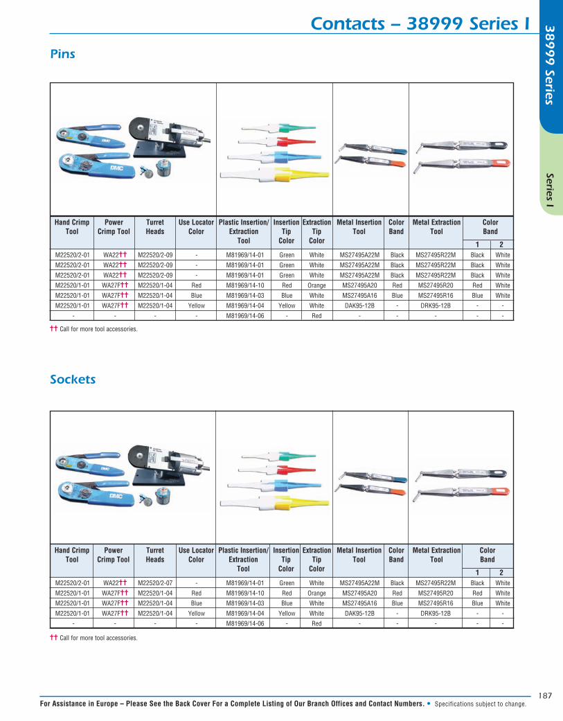
Contacts – 38999 Series I
1 2 M22520/2-01 WA22== M22520/2-09 - M81969/14-01 Green White MS27495A22M Black MS27495R22M Black White
M22520/2-01 WA22== M22520/2-09 - M81969/14-01 Green White MS27495A22M Black MS27495R22M Black White
M22520/2-01 WA22== M22520/2-09 - M81969/14-01 Green White MS27495A22M Black MS27495R22M Black White
M22520/1-01 WA27F== M22520/1-04 Red M81969/14-10 Red Orange MS27495A20 Red MS27495R20 Red White
M22520/1-01 WA27F== M22520/1-04 Blue M81969/14-03 Blue White MS27495A16 Blue MS27495R16 Blue White
M22520/1-01 WA27F== M22520/1-04 Yellow M81969/14-04 Yellow White DAK95-12B - DRK95-12B - -
- - - - M81969/14-06 - Red - - - - -
Hand Crimp Power Turret Use Locator Plastic Insertion/ Insertion Extraction Metal Insertion Color Metal Extraction Color Tool Crimp Tool Heads Color Extraction Tip Tip Tool Band Tool Band Tool Color Color
1 2 M22520/2-01 WA22== M22520/2-07 - M81969/14-01 Green White MS27495A22M Black MS27495R22M Black White
M22520/1-01 WA27F== M22520/1-04 Red M81969/14-10 Red Orange MS27495A20 Red MS27495R20 Red White
M22520/1-01 WA27F== M22520/1-04 Blue M81969/14-03 Blue White MS27495A16 Blue MS27495R16 Blue White
M22520/1-01 WA27F== M22520/1-04 Yellow M81969/14-04 Yellow White DAK95-12B - DRK95-12B - -
- - - - M81969/14-06 - Red - - - - -
Hand Crimp Power Turret Use Locator Plastic Insertion/ Insertion Extraction Metal Insertion Color Metal Extraction Color Tool Crimp Tool Heads Color Extraction Tip Tip Tool Band Tool Band Tool Color Color
Pins
Sockets
== Call for more tool accessories.
== Call for more tool accessories.

188
38
99
9 Series
Series I
In North America: Pricing Delivery: 800-642-8750 • Tech Support: 800-523-0727 • www.peigenesis.com • Specifications subject to change.
38999 Series I – At-A-Glance38
99
9 Series
Additional Connector InformationName:
Company:
Email:
Phone:
CONNECTOR Part #: _______________________________________________
OR# of Contacts: _______________________________________ Sizes & Type:____________________________
CABLE Manufacturer: ________________________________________________________________________ (If Known)
CABLE Part #: _____________________________________ OR Cable OD:____________________________
Use endbell “U” for Menus A, B, C, D & E
Qty: EAU:
Use endbell “CG” for Menus F, G & H
Crimp Termination Only
Choose One Connector Choose One Endbell Choose One Wire Protection