
38324264 Ansys Composites Capability
58
© 2005 ANSYS, Inc. 1 ANSYS, Inc. Proprietary Composites Analysis in ANSYS Composites Analysis in ANSYS
-
Upload
sharan-annapura -
Category
Documents
-
view
40 -
download
4
description
FG
Transcript of 38324264 Ansys Composites Capability

© 2005 ANSYS, Inc. 1 ANSYS, Inc. Proprietary
Composites Analysis in ANSYS Composites Analysis in ANSYS

© 2005 ANSYS, Inc. 2 ANSYS, Inc. Proprietary
Topics Topics
• Composites and Advantages • Traditional Composites Modeling • Interface Delamination and Failure Simulation • ANSYSFibersim Interface

© 2005 ANSYS, Inc. 3 ANSYS, Inc. Proprietary
Composites in the Industry Composites in the Industry
• By the broadest definition, a composite material is one in which two or more materials that are different are combined to form a single structure with an identifiable interface.
• The properties of that new structure are dependant upon the properties of the constituent materials as well as the properties of the interface.
• Additionally, where metal alloys have isotropic characteristics, composites can have very selective directional properties to meet specific application needs.
© 2005 ANSYS, Inc. 4 ANSYS, Inc. Proprietary
Composites in the Industry Composites in the Industry
• Composites used for typical engineering applications are advanced fiber or laminated composites, such as fiberglass, glass epoxy, graphite epoxy, and boron epoxy.
• ANSYS allows you to model composite materials with specialized elements called layered elements. You can perform any structural analysis (including nonlinearities such as large deflection and stress stiffening).

© 2005 ANSYS, Inc. 5 ANSYS, Inc. Proprietary
Benefits of Composites Benefits of Composites
• Stronger and stiffer than metals on a density basis • Capable of high continuous operating temperatures
• Highly corrosion resistant • Electrically insulating/conducting/selectively conducting properties
• Tailorable thermal expansion properties • Exceptional formability • Outstanding durability

© 2005 ANSYS, Inc. 6 ANSYS, Inc. Proprietary
Traditional Composites Analysis Traditional Composites Analysis

© 2005 ANSYS, Inc. 7 ANSYS, Inc. Proprietary
• Element Technology • Material Modeling and Layered Configuration • Failure Criteria • Additional Modeling and PostProcessing
Traditional Composites Modeling Traditional Composites Modeling
© 2005 ANSYS, Inc. 8 ANSYS, Inc. Proprietary
Elements for Composites Analysis Elements for Composites Analysis
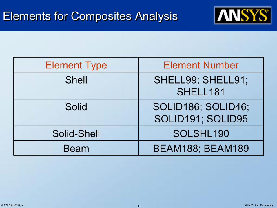
BEAM188; BEAM189 SOLSHL190
SOLID186; SOLID46; SOLID191; SOLID95
SHELL99; SHELL91; SHELL181
Element Number Element Type
Beam SolidShell
Solid
Shell
© 2005 ANSYS, Inc. 9 ANSYS, Inc. Proprietary
SHELL99 Linear Layered Structural Shell Element SHELL99 Linear Layered Structural Shell Element
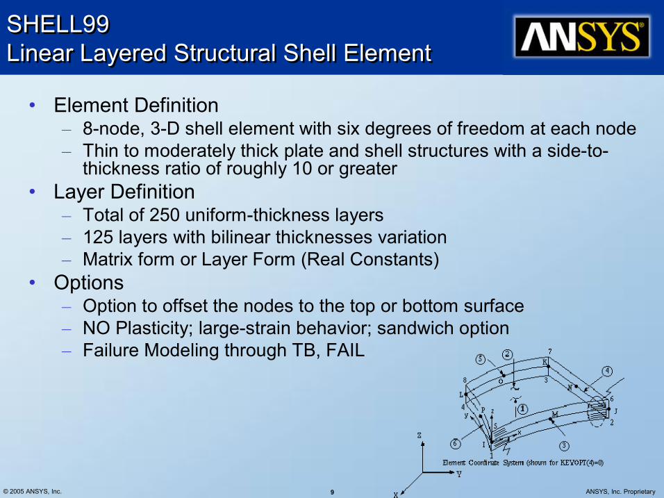
• Element Definition – 8node, 3D shell element with six degrees of freedom at each node – Thin to moderately thick plate and shell structures with a sideto thickness ratio of roughly 10 or greater
• Layer Definition – Total of 250 uniformthickness layers – 125 layers with bilinear thicknesses variation – Matrix form or Layer Form (Real Constants)
• Options – Option to offset the nodes to the top or bottom surface – NO Plasticity; largestrain behavior; sandwich option – Failure Modeling through TB, FAIL
© 2005 ANSYS, Inc. 10 ANSYS, Inc. Proprietary
SHELL91 Nonlinear Layered Structural Shell Element SHELL91 Nonlinear Layered Structural Shell Element
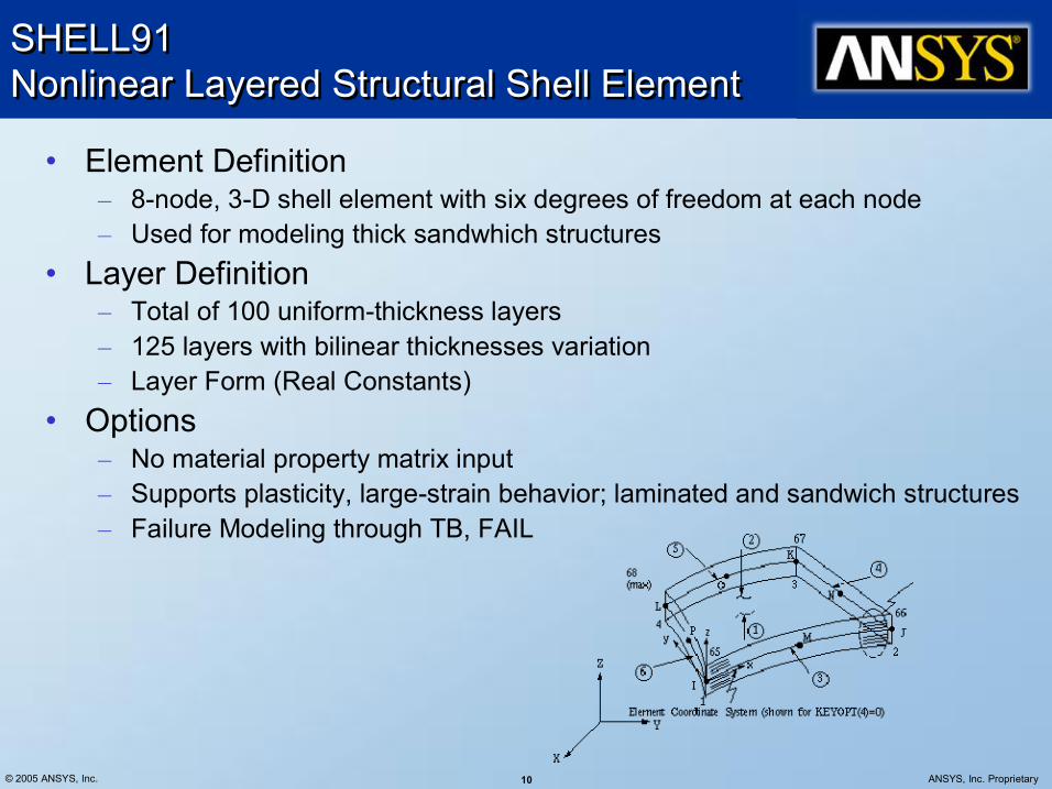
• Element Definition – 8node, 3D shell element with six degrees of freedom at each node – Used for modeling thick sandwhich structures
• Layer Definition – Total of 100 uniformthickness layers – 125 layers with bilinear thicknesses variation – Layer Form (Real Constants)
• Options – No material property matrix input – Supports plasticity, largestrain behavior; laminated and sandwich structures – Failure Modeling through TB, FAIL

© 2005 ANSYS, Inc. 11 ANSYS, Inc. Proprietary
SHELL181 Finite Strain Shell SHELL181 Finite Strain Shell
• Element Definition – 4node 3D shell element with 6 degrees of freedom at each node. – Used for layered applications for modeling laminated composite shells or sandwich construction. (First order shear deformation)
• Layer Definition – Total of 255 uniform/nonuniform section layers – Section commands rather than real constants. – Supports generalized section definition
• Options – Full nonlinear capabilities including large strain and material models – Failure criteria is available via FC and other FCxxx commands.

© 2005 ANSYS, Inc. 12 ANSYS, Inc. Proprietary
SOLID186 3D Layered Structural Solid Element SOLID186 3D Layered Structural Solid Element
• Element Definition – Layered version of the 20node 3D solid element with three
degrees of freedom per node (UX, UY, UZ). – The element can be stacked to model throughthethickness
discontinuities. • Layer Definition
– Total of 250 layers – Section commands rather than real constants.
• Options – Full nonlinear capabilities including large strain – Failure criteria is available via FC and other FCxxx commands.

© 2005 ANSYS, Inc. 13 ANSYS, Inc. Proprietary
SOLID46 3D Layered Structural Solid Element SOLID46 3D Layered Structural Solid Element
• Element Definition – Layered version of the 8node, 3D solid element, SOLID45, with three
degrees of freedom per node (UX, UY, UZ) – Designed to model thick layered shells or layered solids – Can stack several elements to model more than 250 layers to allow
throughthethickness deformation slope discontinuities. • Layer Definition
– Allows up to 250 uniformthickness layers per element. – Allows 125 layers with thicknesses that may vary bilinearly – Userinput constitutive matrix option
• Options – Nonlinear capabilities including large strain – Failure criteria through TB, FAIL option
© 2005 ANSYS, Inc. 14 ANSYS, Inc. Proprietary
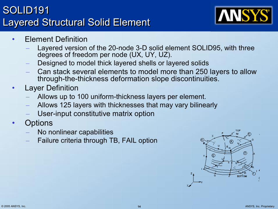
SOLID191 Layered Structural Solid Element SOLID191 Layered Structural Solid Element
• Element Definition – Layered version of the 20node 3D solid element SOLID95, with three
degrees of freedom per node (UX, UY, UZ). – Designed to model thick layered shells or layered solids – Can stack several elements to model more than 250 layers to allow
throughthethickness deformation slope discontinuities. • Layer Definition
– Allows up to 100 uniformthickness layers per element. – Allows 125 layers with thicknesses that may vary bilinearly – Userinput constitutive matrix option
• Options – No nonlinear capabilities – Failure criteria through TB, FAIL option

© 2005 ANSYS, Inc. 15 ANSYS, Inc. Proprietary
SOLSH190 3D Layered Structural Solid Shell SOLSH190 3D Layered Structural Solid Shell
• Element Definition – 8node 3D solidShell element with three degrees of freedom per node (UX,
UY, UZ). – The element can be stacked to model throughthethickness discontinuities. – SOLSH190 can be used for simulating shell structures with a wide range of
thickness (from thin to moderately thick). • Layer Definition
– The element has full nonlinear capabilities including large strain and allows 250 layers for modeling laminated shells.
• Options – Failure criteria is available using the FC commands – Full nonlinear capabilities including large strain and material models – Supported by EORIENT and VEORIENT commands
R1
R3
1
8
6
4 7
5 3
2
A
R3
R1 C
R3 R2
D
B
R3 R2

© 2005 ANSYS, Inc. 16 ANSYS, Inc. Proprietary
Beam188/189 3D Beams Beam188/189 3D Beams • Element Definition
– BEAM188/BEAM189, linear and quadratic versions of the 3D finite strain beam elements with six DOF
– Suitable for analyzing slender to moderately stubby/thick beam structures. This element is based on Timoshenko beam theory. Shear deformation effects are included.
• Layer Definition – Through Section commands – Multi material cross section, custom cross section, inclusion and prediction of
transverse shear stresses • Options
– Nonlinear capabilities including large strain and material models

© 2005 ANSYS, Inc. 17 ANSYS, Inc. Proprietary
Material Modeling & Layered Configuration Material Modeling & Layered Configuration
• The most important characteristic of a composite material is its layered configuration.
• Each layer may be made of a different orthotropic material and may have its principal directions oriented differently.
• For laminated composites, the fiber directions determine layer orientation.
• Two methods are available for defining the layered configuration: i. By specifying individual layer properties ii. By defining constitutive matrices that relate generalized forces
and moments to generalized strains and curvatures

© 2005 ANSYS, Inc. 18 ANSYS, Inc. Proprietary
Individual Layer Properties: First Method Individual Layer Properties: First Method
• With this method, the layer configuration is defined layerbylayer from bottom to top.
• The bottom layer is designated as layer 1, and additional layers are stacked from bottom to top in the positive Z (normal) direction of the element coordinate system.
• At times, a physical layer will extend over only part of the model. In order to model continuous layers, these dropped layers may be modeled with zero thickness.
© 2005 ANSYS, Inc. 19 ANSYS, Inc. Proprietary
Individual Layer Properties Individual Layer Properties
• Material Property – MP command is used to define the linear material properties. – TB command is used to define the nonlinear material data tables
• The only difference is that the material attribute number for each layer of an element is specified in the element's real constant table or Section data
• The linear material properties for each layer may be either isotropic or orthotropic
• Material property directions are parallel to the layer coordinate system, defined by the element coordinate system and the layer orientation angle

© 2005 ANSYS, Inc. 20 ANSYS, Inc. Proprietary
Defining Layer Data Defining Layer Data
• Using Layered sections through the Section Tool – For each layer, the following are specified in the section definition through the section commands; or through the Section Tool (SECTYPE, SECDATA) (accessed with the SECNUM attributes).
– Material properties (via a material reference number MAT)
– Layer orientation angle commands (THETA) – Layer thickness (TK) – Number of integration points per layer (NUMPT)

© 2005 ANSYS, Inc. 21 ANSYS, Inc. Proprietary
Layer Data Definition Layer Data Definition
• Layer Orientation Angle – This defines the orientation of the layer coordinate system with respect to the element coordinate system.
– It is the angle (in degrees) between Xaxes of the two systems. By default, the layer coordinate system is parallel to the element coordinate system.
• Layer Thickness – If the layer thickness is constant, you only need to specify TK(I), the thickness at node I. Otherwise, the thicknesses at the four corner nodes must be input.
– Dropped layers may be represented with zero thickness. • Number of integration points per layer
– This allows you to determine in how much detail the program should compute the results.
– For very thin layers, when used with many other layers, one point would be appropriate. But for laminates with few layers, more would be needed. The default is 3 points.

© 2005 ANSYS, Inc. 22 ANSYS, Inc. Proprietary
Shell Section Data Shell Section Data
• SecType, SecId, SHELL SHELL, Name • SecData, Thick, MatID, Ori, numSectPt
Thick Layer Thickness MatID Material ID for layer Ori Layer Orientation numSectPt Number of integration points thru layer thickness Repeat as many times as needed
© 2005 ANSYS, Inc. 23 ANSYS, Inc. Proprietary
Constitutive Matrices: Second Method Constitutive Matrices: Second Method
• This is an alternative to specifying the individual layer properties
• Available as an option KEYOPT(2) for SOLID46 and SHELL99.
• The matrices, which represent the forcemoment and strain curvature relationships for the element, must be calculated outside the ANSYS program
• They can be included as part of the solution printout with KEYOPT(10).
• The main advantages of the matrix approach are: – It allows you to incorporate an aggregate composite material behavior.
– A thermal load vector may be supplied. – The matrices may represent an unlimited number of layers. – The terms of the matrices are defined as real constants.
© 2005 ANSYS, Inc. 24 ANSYS, Inc. Proprietary
Preintegrated General Shell Sections Preintegrated General Shell Sections
• You can now define homogenous shell section behavior directly via preintegrated general shell sections, a method commonly used in analyses involving laminated composite structures.
• With preintegrated shell sections (SECTYPE,,GENS), you can directly specify the membrane, bending, and coupling properties.
• The preintegrated method also allows analysis of complex geometry (with repeated patterns such as corrugated sheets) using equivalent shell section properties.
• You can use preintegrated general shell sections when using the SHELL181 element, provided that linear elastic material behavior is acceptable.
• Preintegration – Requires fewer system resources because numerical integration through the thickness of the shell is not required.
– Allows import of homogenous sectionstiffness constants evaluated in other analyses or by thirdparty, specialpurpose software tools.

© 2005 ANSYS, Inc. 25 ANSYS, Inc. Proprietary
Node Offset Node Offset
• For SHELL181 using sections defined through the section commands, nodes can be offset during the definition of the section, using the SECOFFSET command.
• For SHELL91, and SHELL99 the node offset option (KEYOPT(11)) locates the element nodes at the bottom, middle or top surface of the shell.
© 2005 ANSYS, Inc. 26 ANSYS, Inc. Proprietary
Failure Criteria Failure Criteria
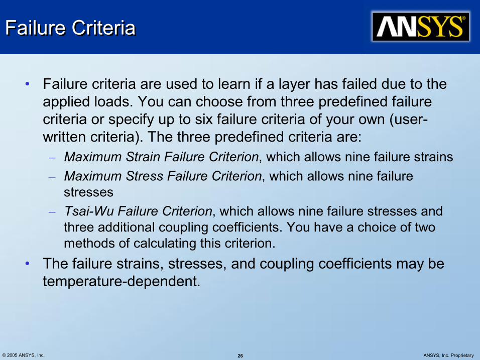
• Failure criteria are used to learn if a layer has failed due to the applied loads. You can choose from three predefined failure criteria or specify up to six failure criteria of your own (user written criteria). The three predefined criteria are: – Maximum Strain Failure Criterion, which allows nine failure strains – Maximum Stress Failure Criterion, which allows nine failure stresses
– TsaiWu Failure Criterion, which allows nine failure stresses and three additional coupling coefficients. You have a choice of two methods of calculating this criterion.
• The failure strains, stresses, and coupling coefficients may be temperaturedependent.

© 2005 ANSYS, Inc. 27 ANSYS, Inc. Proprietary
Specifying Failure Criteria Specifying Failure Criteria
• Failure criteria are commonly used for orthotropic materials. They can be input using either the FC commands or the TB commands
• TB Command: TB, FAIL Composite material failure data – Applies to SOLID46, SHELL91, SOLID95, SHELL99, SOLID191
• The failure criteria table is started by using the TB command (with Lab = FAIL). The data table is input in two parts: – the failure criterion keys – the failure stress/strain data.
• Data not input are assumed to be zero. The six failure criterion keys are defined with the TBDATA command following a special form of the TBTEMP command [TBTEMP,,CRIT] to indicate that the failure criterion keys are defined next

© 2005 ANSYS, Inc. 28 ANSYS, Inc. Proprietary
TB, FAIL and FC Commands TB, FAIL and FC Commands
TB,FAIL,1,2 ! Data table for failure criterion, material 1, ! no. of temperatures = 2 TBTEMP,,CRIT ! Failure criterion key TBDATA,2,1 ! Maximum Stress Failure Criterion (Const. 2 = 1) TBTEMP,100 ! Temperature for subsequent failure properties TBDATA,10,1500,,400,,10000 ! X, Y, and Z failure tensile stresses (Z value ! set to a large number) TBDATA,16,200,10000,10000 ! XY, YZ, and XZ failure shear stresses TBLIST TBTEMP,200 ! Second temperature TBDATA,...
FC,1,TEMP,, 100, 200 ! Temperatures FC,1,S,XTEN, 1500, 1200 ! Maximum stress components FC,1,S,YTEN, 400, 500 FC,1,S,ZTEN,10000, 8000 FC,1,S,XY , 200, 200 FC,1,S,YZ ,10000, 8000 FC,1,S,XZ ,10000, 8000 FCLIST, ,100 ! List status of Failure Criteria at 100.0 degrees FCLIST, ,150 ! List status of Failure Criteria at 150.0 degrees FCLIST, ,200 ! List status of Failure Criteria at 200.0 degrees PRNSOL,S,FAIL ! Use Failure Criteria

© 2005 ANSYS, Inc. 29 ANSYS, Inc. Proprietary
Failure Criteria … Failure Criteria …
• The TB commands (TB, TBTEMP, and TBDATA) can be used only for SHELL91, SHELL99, SOLID46, or SOLID191, but the FC and FCLIST commands can be used for any 2D or 3D structural solid element or any 3D structural shell element.
• Some notes about specifying failure criteria: – The criteria are orthotropic, so you must input the failure stress or failure strain values for all directions. (The exception is that compressive values default to tensile values.)
– If you don't want the failure stress or strain to be checked in a particular direction, specify a large number in that direction
– Userwritten failure criteria may be specified via user subroutines USRFC1 through USRFC6. These subroutines should be linked with the ANSYS program beforehand
© 2005 ANSYS, Inc. 30 ANSYS, Inc. Proprietary
Pre & Post Processing Commands Pre & Post Processing Commands
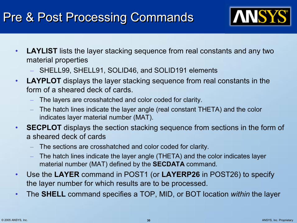
• LAYLIST lists the layer stacking sequence from real constants and any two material properties – SHELL99, SHELL91, SOLID46, and SOLID191 elements
• LAYPLOT displays the layer stacking sequence from real constants in the form of a sheared deck of cards. – The layers are crosshatched and color coded for clarity. – The hatch lines indicate the layer angle (real constant THETA) and the color
indicates layer material number (MAT). • SECPLOT displays the section stacking sequence from sections in the form of
a sheared deck of cards – The sections are crosshatched and color coded for clarity. – The hatch lines indicate the layer angle (THETA) and the color indicates layer
material number (MAT) defined by the SECDATA command. • Use the LAYER command in POST1 (or LAYERP26 in POST26) to specify
the layer number for which results are to be processed. • The SHELL command specifies a TOP, MID, or BOT location within the layer

© 2005 ANSYS, Inc. 31 ANSYS, Inc. Proprietary
Interlaminar shear stresses Interlaminar shear stresses
• Interlaminar shear stresses are usually important at the free edges of a model.
• For relatively accurate interlaminar shear stresses at these locations, the element size at the boundaries of the model should be approximately equal to the total laminate thickness.
• For shells, increasing the number of layers per actual material layer does not necessarily improve the accuracy of interlaminar shear stresses.

© 2005 ANSYS, Inc. 32 ANSYS, Inc. Proprietary
Interlaminar shear stresses Interlaminar shear stresses
• With elements SOLID46, SOLID95, SOLSH190 and SOLID191, however, stacking elements in the thickness direction should result in more accurate interlaminar stresses through the thickness.
• Interlaminar transverse shear stresses in shell elements are based on the assumption that no shear is carried at the top and bottom surfaces of the element.
• These interlaminar shear stresses are only computed in the interior and are not valid along the shell element boundaries.
• Use of shelltosolid submodeling is recommended to accurately compute all of the free edge interlaminar stresses.

© 2005 ANSYS, Inc. 33 ANSYS, Inc. Proprietary
0/90 Symmetric Composite Example 0/90 Symmetric Composite Example
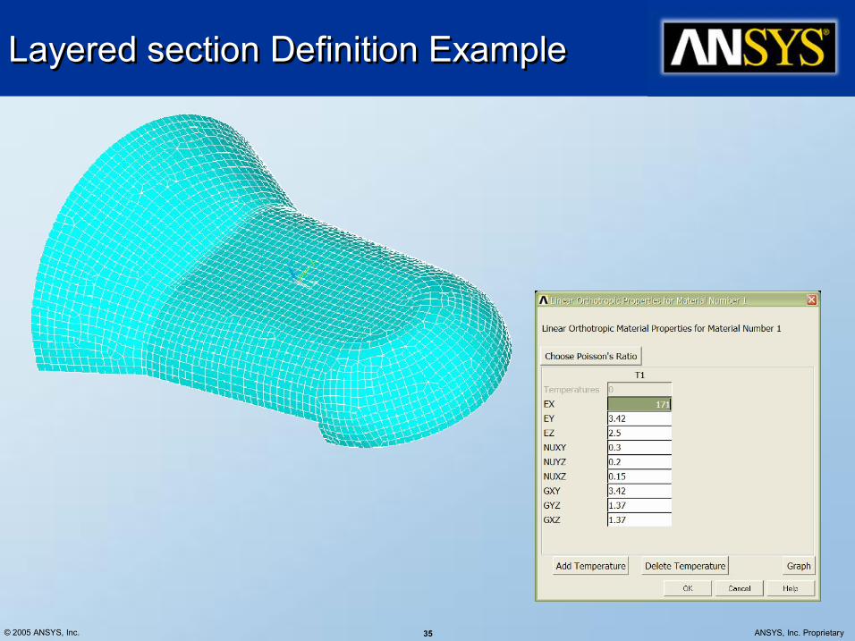
EX = 171GPa EY = 3.42GPa EZ = 3.42GPa PRXY=0.25 PRYZ=0.25 PRXZ=0.25
GXY = 3.42GPa GYZ = 1.37GPa GXZ = 1.37GPa

© 2005 ANSYS, Inc. 34 ANSYS, Inc. Proprietary
0/90 Symmetric Composite Example … 0/90 Symmetric Composite Example …
Solid Shell 190
h/L = 0.2; # layers: 30
Solid Shell 190
h/L = 0.06; # layers: 12
© 2005 ANSYS, Inc. 35 ANSYS, Inc. Proprietary
Layered section Definition Example Layered section Definition Example

© 2005 ANSYS, Inc. 36 ANSYS, Inc. Proprietary
Layered section Definition Example … Layered section Definition Example …
SECPLOT Command
© 2005 ANSYS, Inc. 37 ANSYS, Inc. Proprietary
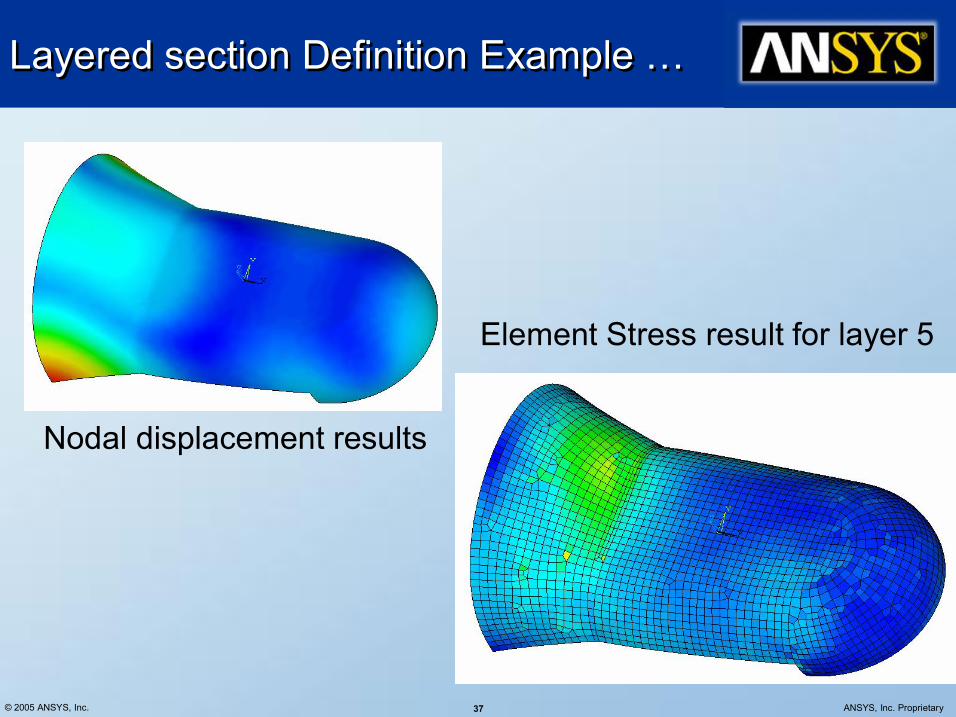
Layered section Definition Example … Layered section Definition Example …
Element Stress result for layer 5
Nodal displacement results

© 2005 ANSYS, Inc. 38 ANSYS, Inc. Proprietary
Interface Delamination and Failure Interface Delamination and Failure
© 2005 ANSYS, Inc. 39 ANSYS, Inc. Proprietary
Interface Delamination and Failure Interface Delamination and Failure
• An interface exists anywhere two materials are joined together.
• The interface between the layers of a composite structure is of special interest, because when this type of structure is subjected to certain types of external loading, the failure process (delamination) takes on a unique character.
• Interface delamination is traditionally simulated using fracture mechanics methods, such as nodal release technique.
• Alternatively, you can use the cohesive zone model to simulate interface delamination and other fracture pheneomenon.

© 2005 ANSYS, Inc. 40 ANSYS, Inc. Proprietary
Cohesize Zone Model Cohesize Zone Model
• This approach introduces failure mechanisms by using the hardeningsoftening relationships between the separations and incorporating the corresponding tractions across the interface.
• This technique is also well suited for modeling the fracture process in a homogenous medium, since fracture can be viewed as a separation process between two surfaces
• Interface delamination and failure simulation is performed by first separating the model into two components or groups of elements.
• A cohesive zone is then defined between these two groups. ANSYS offers a set of interface elements designed specifically to represent the cohesive zone between the components and to account for the separation across the interface.
© 2005 ANSYS, Inc. 41 ANSYS, Inc. Proprietary
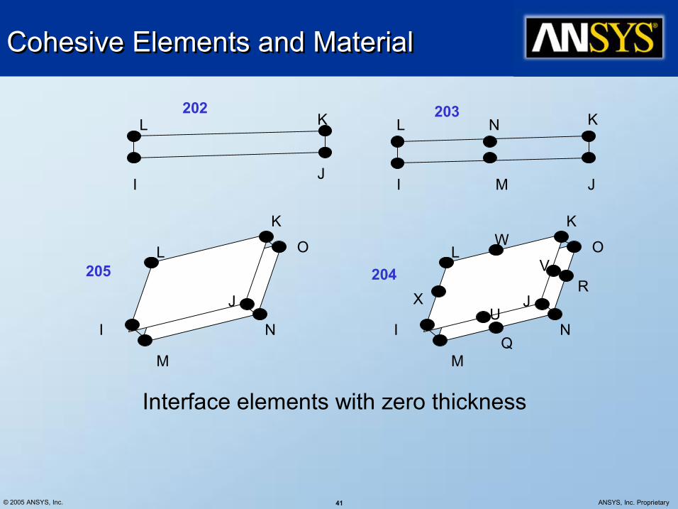
Cohesive Elements and Material Cohesive Elements and Material
Interface elements with zero thickness
I J
L K
I J
K L
M
N 202 203
I
J
K
L
M
N
O
I
J
K
L
M
N
O
Q
R
U
V
W
X
205 204
© 2005 ANSYS, Inc. 42 ANSYS, Inc. Proprietary
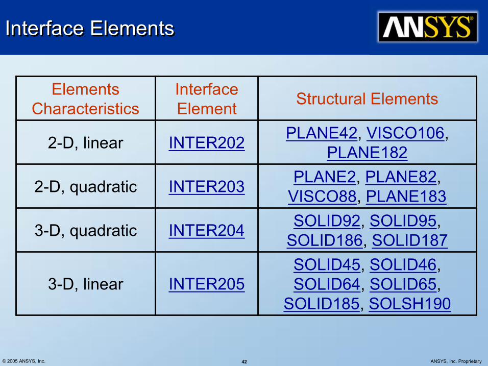
Interface Elements Interface Elements
SOLID45, SOLID46, SOLID64, SOLID65,
SOLID185, SOLSH190 INTER205 3D, linear
SOLID92, SOLID95, SOLID186, SOLID187 INTER204 3D, quadratic
PLANE2, PLANE82, VISCO88, PLANE183 INTER203 2D, quadratic
PLANE42, VISCO106, PLANE182 INTER202 2D, linear
Structural Elements Interface Element
Elements Characteristics
© 2005 ANSYS, Inc. 43 ANSYS, Inc. Proprietary
Cohesive Element and Material Cohesive Element and Material
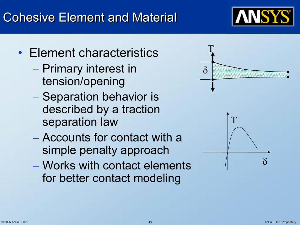
• Element characteristics – Primary interest in tension/opening
– Separation behavior is described by a traction separation law
– Accounts for contact with a simple penalty approach
– Works with contact elements for better contact modeling
T
δ
T
δ

© 2005 ANSYS, Inc. 44 ANSYS, Inc. Proprietary
Cohesive Element and Material Cohesive Element and Material
• Material definition – Material model parameters
– Data input TB,CZM,mat,ntemp,npts,EXPO TBDATA,1,c1,c2,c3 C1 – C2 – C3 –
max σ n δ t δ
max σ
n δ
t δ
T
δ
• Cohesive zone model – Exponential model
Surface potential
Traction across the surface
Δ Δ T
∂ φ ∂
= ) (
δ δ
−
δ δ
−
δ δ
+ − δ σ = φ n
n 2 t
2 t
n
n n max exp exp 1 1 e ) (Δ

© 2005 ANSYS, Inc. 45 ANSYS, Inc. Proprietary
Interface Delamination Example Interface Delamination Example
Problem description
U
U Length: 100 mm Width: 20 mm
h: 3 mm
a: 30 mm
Reference: Alfano, G. and Crisfield, M. A., “Finite element interface models for the delamination analysis of laminated composites: mechanical and computational issues”, International Journal for Numerical Methods in Engineering, 2001, 50:17011736.

© 2005 ANSYS, Inc. 46 ANSYS, Inc. Proprietary
Interface Delamination Example … Interface Delamination Example …
Cohesive Zone Modeling
Cohesive Zone Elements

© 2005 ANSYS, Inc. 47 ANSYS, Inc. Proprietary
Interface Delamination Example … Interface Delamination Example …

© 2005 ANSYS, Inc. 48 ANSYS, Inc. Proprietary
Interface Delamination Example … Interface Delamination Example …
Comparision
0.00E+00
1.00E+01
2.00E+01
3.00E+01
4.00E+01
5.00E+01
6.00E+01
0.00E+00 1.00E+00 2.00E+00 3.00E+00 4.00E+00 5.00E+00 6.00E+00 7.00E+00 8.00E+00 9.00E+00 DisplacementUy (mm)
Reaction ForceFy (N
)
C1=37 N/mm^2, C2=0.0025 mm Element Type: Inter202
Element length: 0.4 mm
C1=25 N/mm^2, C2=0.004 mm Element Type: Inter202
Element length: 0.5 mm
Reference results Element length: 1 mm
C1=25 N/mm^2, C2=0.004 mm Element Type: Inter205
Element length: 0.5 mm

© 2005 ANSYS, Inc. 49 ANSYS, Inc. Proprietary
ANSYS – Fibersim Interface ANSYS – Fibersim Interface

© 2005 ANSYS, Inc. 50 ANSYS, Inc. Proprietary
ANSYS Fibersim Interface ANSYS Fibersim Interface
• VISTAGY, Inc. develops and markets the FiberSIM suite of software for composite design and manufacturing.
• www.vistagy.com/products/fibersim.htm • By supporting the composite engineering process from the early
stages of design all the way through to manufacturing, FiberSIM enables engineers to fully exploit these materials quickly and cost effectively.
• FiberSIM provides CADintegrated software solutions for:
– Managing plies – Assessing producibility – Creating flat patterns – Generating properties for analysis – Producing design documentation – Generating offset laminate surfaces – Exporting flat patterns to manufacturing – Programming laser projection systems – Interfacing with fiber placement machines

© 2005 ANSYS, Inc. 51 ANSYS, Inc. Proprietary
FiberSIM Interface FiberSIM Interface
• The FiberSIM Analysis interface provides a complete and detailed description of the final part design, enabling accurate verification of the part's performance
• It has geometry available using .xml file that has the following information available: – Names of all layers – Which layers are used (not droppedoff) – The orientation angle of all layers
© 2005 ANSYS, Inc. 52 ANSYS, Inc. Proprietary
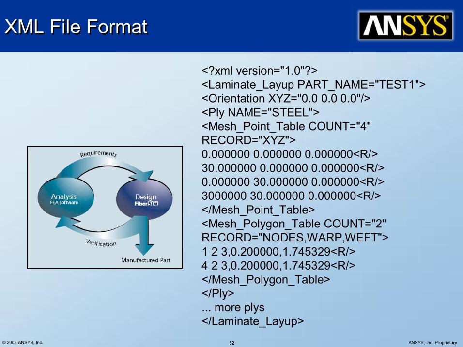
XML File Format XML File Format
<?xml version="1.0"?> <Laminate_Layup PART_NAME="TEST1"> <Orientation XYZ="0.0 0.0 0.0"/> <Ply NAME="STEEL"> <Mesh_Point_Table COUNT="4" RECORD="XYZ"> 0.000000 0.000000 0.000000<R/> 30.000000 0.000000 0.000000<R/> 0.000000 30.000000 0.000000<R/> 3000000 30.000000 0.000000<R/> </Mesh_Point_Table> <Mesh_Polygon_Table COUNT="2" RECORD="NODES,WARP,WEFT"> 1 2 3,0.200000,1.745329<R/> 4 2 3,0.200000,1.745329<R/> </Mesh_Polygon_Table> </Ply> ... more plys </Laminate_Layup>
© 2005 ANSYS, Inc. 53 ANSYS, Inc. Proprietary
XML File XML File
• The XML file has the following information available: – The names of all layers – Which layers are used (not droppedoff) at any one point
– The orientation angle of all layers used at any one point

© 2005 ANSYS, Inc. 54 ANSYS, Inc. Proprietary
FibreSim Interface … contd. FibreSim Interface … contd.
• The XML file does not describe the laminate completely. Also needed are: – Layer thicknesses – Layer material properties
• These are provided using the SECDATA and MP commands in ANSYS.
• SHELL99 and SHELL181 are supported
sect,4,shell,fibersim, lamin1 secd,0.2,1,,,layer1 secd,1.0,2,,,layer2

© 2005 ANSYS, Inc. 55 ANSYS, Inc. Proprietary
Other Input information Other Input information
• Additionally, the following input are available: – Offset selection – Added mass per unit area – Distance and angle tolerances between the FS model and the ANSYS model
– Debug output keys
© 2005 ANSYS, Inc. 56 ANSYS, Inc. Proprietary
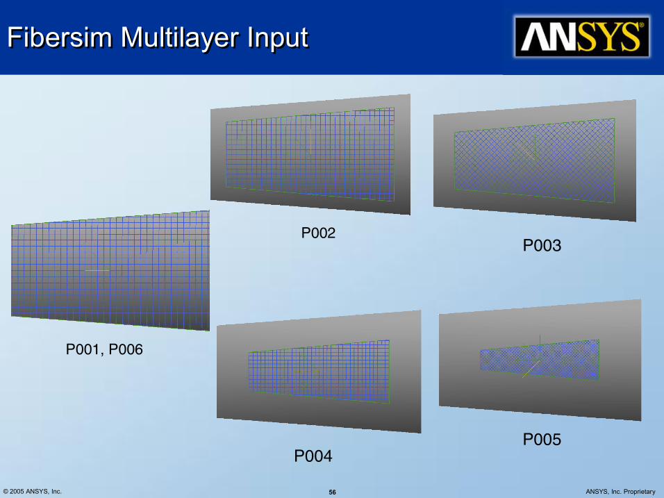
Fibersim Multilayer Input Fibersim Multilayer Input
P001, P006
P002 P003
P004 P005

© 2005 ANSYS, Inc. 57 ANSYS, Inc. Proprietary
ANSYSFibersim Interface Example ANSYSFibersim Interface Example
t1 = 1.0e3 ! ! ************ Import FiberSIM data ******* ! sect,1,shell,fibersim,xml_filename ! secd,t1,1,,,P001 secd,t1,1,,,P002 secd,t1,1,,,P003 secd,t1,1,,,P004 secd,t1,1,,,P005 secd,t1,1,,,P006 ! secr,xml_filename,xml secn,1 ! thicktol = t1*50 edgetol = 100 angtol = 180 secc,,,,,,,,,thicktol,edgetol,angtol,0
ANSYS Shell Mesh
Displacement Results
© 2005 ANSYS, Inc. 58 ANSYS, Inc. Proprietary
Conclusion Conclusion
• ANSYS offers a range of capability for composites analysis • Traditional composites capability includes shell, solid and beam
elements with advanced section definition and failure criteria specification capability
• Advanced delamination modeling capability through cohesive zone elements extends the composites capability include failure modeling
• Interface to Fibersim brings composites analysis in ANSYS closer to CAD design and manufacturing by providing exact fiber orientations for use in generating laminate properties


![Mechanical Performance Analysis Based on ANSYS of Concrete … · [2] Rochette P, Labossière P. Axial testing of rectangular column models con composites. Journal of Composites for](https://static.fdocuments.net/doc/165x107/61409f702e263e64232a2e9d/mechanical-performance-analysis-based-on-ansys-of-concrete-2-rochette-p-labossire.jpg)


