376 ELECTROMAGNETIC THEORY, CH, VII,
65
376 ELECTROMAGNETIC THEORY, CH, VII, In the distortionless case, Z is the constant Lv. The re- flected waves are then of the same type as the incident if Z 0 and Z 1 are also constant-that is, mere resistances in the obvious case, or else equivalent distortionless circuits. But in the theory of this chapter, Z= ( R + �p ) I =Lv ( p + p + ) 1 , (3) K+Sp p +p - so we cannot get clean reflection without change of type unless the terminal resistance operator is a constant multiple of Z, which means that Z0 and Z1 may be other lines with suitably chosen constants, or else practical imitations. In all cases of this kind, it is sufficient to find the formula r the initial wave. All the llowing waves may be obtained om it by changing the origin and argument suitably. Let V O be voltage impressed at x = 0, and V 1 the first wave. Then V 1 =C qz V 0 . ( 4) On arrival at x = l, reflection begins. To produce the reflected wave, put x= l in V i , multiply by p 1 , and then introduce the attenuator {(l-z>, Thus (5) is the second wave. On its arrival at x=O, the third wave begins. Put =0 in V 2 , multiply by p 0 , and then by e - qz , producing (6) Observe that to get V 3 from V 1 we multiply by p 0 p 1 c 1 • In the same way V 4 is got om V 2 , and any V , from V n• So the total Vis V = (1 + P oP 1 c 2 q 1 + P o 2 P ?c q 1 + . .. )( V t + V 2), (7 ) or, which means the same, E z +p t(21) V=--�- --V 0 , (8) 1- PoP1c l which is the condensed rm of solution for Vin terms of V 0 • The latter is npt. the real voltage at x 0, except when the line i3 infinitely long, when, however, ( 4) above is sufficient. Also
Transcript of 376 ELECTROMAGNETIC THEORY, CH, VII,

376 ELECTROMAGNETIC THEORY, CH, VII,
In the distortionless case, Z is the constant Lv. The reflected waves are then of the same type as the incident if Z0
and Z1
are also constant-that is, mere resistances in theobvious case, or else equivalent distortionless circuits. But inthe theory of this chapter,
Z= (R+�p) I =Lv(p+p+o-) 1, (3)K+Sp p+p-o-so we cannot get clean reflection without change of type unlessthe terminal resistance operator is a constant multiple of Z,which means that Z0 and Z1 may be other lines with suitablychosen constants, or else practical imitations. In all cases ofthis kind, it is sufficient to find the formula for the initialwave. All the following waves may be obtained from it bychanging the origin and argument suitably.
Let VO
be voltage impressed at x = 0, and V 1 the first wave.Then
V1 = CqzV 0. ( 4)
On arrival at x = l, reflection begins. To produce the reflectedwave, put x= l in V
i, multiply by p
1, and then introduce the
attenuator {-q(l-z>, Thus(5)
is the second wave. On its arrival at x=O, the third wavebegins. Put Q:=0 in V
2, multiply by p0, and then by e-qz,
producing(6)
Observe that to get V3
from V1 we multiply by p0p1
c21J1• Inthe same way V 4 is got from V
2, and any V,. from V n-2• So
the total V isV = (1 + PoP1
c2q1 + Po2P?c-1q1 + ... )(Vt + V 2), (7)
or, which means the same,E-qz + p t-q(21-o:) V=--�-.!.--V
0, (8)
1- PoP1c2ql
which is the condensed form of solution for Vin terms of V0•
The latter is npt. the real voltage at x""' 0, except when the linei3 infinitely long, when, however, (4) above is sufficient. Also

ELECTROllAGNF.TfC WAYES. 877
the relation bPtween V0 and e, when e is impressed force producing V0, is
(9)
Operational solutions of the condensed kind, as (8), and its modifications, may be developed to Fourier series by means of the expansion theorem, § 282 and after. It is unfortunate that the results, save in relatively simple cases, should be unmanageable for numerical calculation. Even to prove their identity with the wave series by rigorous methods involves the evaluation of definite integrals of a formidable nature. But that is hardly the right way to work. When in mathematical physics we find, by following Fourier's methods, say, that our solutions involve certain series and integrals, not recognisable as known forms, the practical way to evaluate them is to find another way of solving the same problems, and then equate the results to the former ones. This may not be rigorous. But it may be better than that Whole families of new results may " tumble out" of themselves, altogether beyond rigorous treatment. But this is an 3pisode.
If we write
(10)
although we know that only a limited number of terms on the right side may be in existence, we may do so without ambiguity, whether the individual waves are represented by algebraical formulre or by operational formulre. The latter are ( 4 ), (5), (G), &c., the former are their algebrisations. In (8) all the waves are added, though they may not be in existence. But there is no metaphysics here. If non-existent they do nothing. The function V0 is zero before and begins when t = 0. The derived wave V1 · has the same property, modified by the operator e·q:z:. It only exists for positive values oft which are not less than x/v. Or, more shortly, it begins when t reaches the value x/v. Similarly V2 begins when t reaches (2l - x)/v ; Vs begins when t reaches (2l + x)/v, and so on. Before these epochs they are zero. So, considering the complete formula (10), whether it be algebraical or operational, we see that the terms come into existence one after another at the proper

378 ELECTRO:llAGNETIC THEORY, CH, VII,
moments indicated by their structure. Thus, from t = 0 up to t=l/v, we have V = V1 only, and its range is only from x=O to vt. From t = l/v up to 2l/v, we have V = V1 only, between x=O and 2l-x, but V = V1 + V2 beyond, up to x=l. And so on to the rest of the waves. It is only necessary to follow the wave front running to and fro at speed v to see the extent of operation of the waves.
In the algebrised formulrn themselves, the positivity of the arguments limits the existence of special terms. Thus, if the first wave involves w/P,.(z1
), where w1=icr(t-x/v), z1=cr(t2 -x2/v2)1; (11)
then the second wave will involve wtPn(z2), where w2 = fcr{t - (2l - x)/v}, z2 = cr{t2
- (2l - x)2/v2}!; (12)and the third will involve w
g"P,.(z
3), where
w3 = ½cr{t-(2l +x)/v}, z3 = cr{t2
- (2l + x)2/v2}1; (13)and so on. In all cases the w's must be positive, or at least zero, and the same as regards the quantities under the radical. This consideration makes the formula (10) explicitly correct all along.
Terminal Reflection without Loss. Wave Solutions. § 397. Now, let V0 be known. Let it be expanded in the
form V
0=cPt � A,.I,.(crt),
of which I have given numerous examples. explained, the first wave is expressed by
V -pt -..;, A wtp ( ) 1=
E ,,:;.,,; n- nZ1,
and the second by �
V2 = P1€-pt � A,.l�rP .. (z2), �
and the third by
(14) Then, as before
(15)
(16)
w" V3=PoP1£-pt �A,.� P,.{z3), (17)
and so on, introducing the factors p1
and Po alternately, and changing x to 2Z -x, 2l + x, 4l -x, 4l + x, &c.

ELECTRO:uAG:IBTIC WAVES. 879
Thus, the solution is fully completed when p0 and p1
are constants. When not constants, but operators, then there is change of type. Equations (15), (16), (17) are still true, but require the performance of the p
0 and p
1 operations to fully
algebrise them. How to do this will come later. At present note that there are four practical cases in which the reflection coefficients are constants (besides the general case of terminal arrangements having resistance operators constant multiples of that of the line), namely terminal short-circuit or insulation at either or both ends. There is complete negative reflection of voltage at a short-circuit, that is, p
0 or p
1 = -1 ;
and there is complete positive reflection of voltage at a disconnection, th!!-t is, p
0 or p
1 = + 1. The current is also completely
reflected, but in the opposite sense to the voltage. So, by letting p
0 or p
1 be + 1 or -1, we can construct the full solu
tions for a line of finite length. [In this connection the case of a circuit closed upon itself should be noticed. Here an impressed force at any part of the circuit generates two waves, to right and left respectively. They are similar as regards C, but opposite as regards V. They are also the same as if they entered infinitely long cables. But they travel round and round and overlap each other and one another ; so the resultant V and C are represented by infinite series. of waves just as in cases of terminal reflection. The above description is sufficient to build up the complete formulre.]
It usually happens that the initial wave is expressed by an infinite series of the form (15). Then, of course, all the derived waves are similar infinite series. There is only one practical case where the waves are expressed by a single term. If either there be no leakage, and V0 be steady, which is thoroughly practical; or else, next best, if there be leakage, but V
0 impressed be made to subside according to the leakage
law, i.e., V0=e
0cKt/S where e
0is steady; then, as before seen,
cl= eo Po(z
1)"-pt (18)
Lv
is the first current wave. It follows that if there be shortcircuit at both terminals, the complete result due to theimpressed force V
0 at x=O is
C ={� . .,-pt{ P0(z1) + Po(Zi?) + P0(z,) + Po(z,) + ··} (19)

380 ELECTROMAGNETIC THEORY, CH. VII.
because there is complete positive reflection of the current atthe terminals. On the other hand, under the same circumstances, the firstvoltage wave is, by§ 381, equation (33), V1 = e
0€- pt{ P0(z1) + 2w1P1(z1) + 2 itP2(z1) +. ·l (20)
It follows that the second wave isV� = -e
0E�Pt{ P
0(z,.) + 2w2Pi(z2) + 2it{P2(z2) + ··l (21)
because there is negative reflection of the voltage. And thethird wave is {
ws2 l V8 = + e0E-pt Po(z8) + 2w8P1(zs) + 2 � P2(zs) + ...
J, (22)
and so on. When a steady V0
is applied to a distortionless circuit thecurve of V (and C also) is shaped according to c KxJSv, orc KtJS, if x=vt. If, therefore, we let V0
decrease with thetime according to the same law, the resulting curve of V willbe a straight line, and V = cKt/S x constant will represent thewave, extending from x=O to vt. No doubt this simplicity is the ultimate reason why the primary wave of C just treatedis represented by one term only. If the line is insulated at a;= l, whilst still short-circuitedat x=O, we have p0 = -1, p1 = +I. The complete C wave istherefore0= �: €-pt{ Po(.�1) -P0(z2) -Po(zs) + Po(z4) + ... }· (23)
If insulated at x = 0 there is negative reflection of thecurrent. An impressed e produces no C, and therefore no Veither. We must shift e away from the origin, or make someother change before e can work. Comparison with Fourier Series. Solution of Definite
Integrals.
§ 398. Now, to show the connection with the Fourier seriesform of solution, take the fundamental case of (19), and do it

ELECTRO)IAGNETIQ WAVES. 881by the expansion theorem for normal solutions. The first andsecond waves are
C - -qz;vo 1-E i-•
therefore the complete C is -e,,i _ E
--qz - Pi �
:!l-z) Vo C=(l+PoPtE + ... )(C1 +C2)- (l "') z·
- Po P1•·q
(24)
(25)
Here we must put p0 = - 1 = p
1, and V
0 = e0cKt1S = eirr-p)t. Theresult is
C=coshq(l-x) _q_/rr-p)te ,shinql R +Lp 0 (26)
and the corresponding V formula isV_shinq(l-x) (rr-p)t - --c-'c-'--� E e0• shinql (27)
We see that the determinantal equation gives ql=n-rri in thecase of V, excepting the zero root, but that in the case of Cthere is an additional root p = - R/L. But in the expansiontheorem the operand is steady. Here it is a function of thetime. This is easily put right. Shift the exponential timefunction to the left, whilst increasing p to p + u - p at thesame time. Then (26) becomes C
- (rr -p)t cosh(l - x) (p2 + 2JJ<T)l/v (v2 + 2p<r)l/v (28)-E shinl(p2+2po-)l/v L(p+2<r) eo, where the operand is now steady. The expansion theoremturns it (by the usual work, presenting nothing special) to
where C- (rr -p)t {l - e-2rrt 2e-rrt� mrx sin At} -e0e 2Ll<r +Lf-�COS-l- -X--- ,
A= {('mn-fl)2 - <r2}½ = ( m2v2- <r2)!, (29)
(30)
and in the summation n is integral, ranging from I to c,,. This solution (29) is therefore equivalent to (19) above. In a similar manner the expansion theorem turns (�7) to( _ )t { ( x) 2E -rrt I . mrx( <r
. ) } v = eoE
rr P 1 -1 - -7r-� n Slll -l- cos+ X Slll At ,
which is equivalent to the si{m of (20), (21), (22), &c. (31)

382 ELECTROMAGNETIC THEORY. CH. Vil.
If the line is in6nitely long, the summations become definite integrals. Put mr/l = rn, then the step dm is 7r/l, and (29) becomes
_ t 2 j"' sin At 0=e0e P - cos mx-- dm,Lr. o A (32) where,\ is as in the second form of (30). At the same time there is only one wave, viz., (18) above, the rest having no chance to make a start. So, equating (18) and (32), we obtain
2vf"' sin At Po(z1)=- cosmx--dm. (33) 7l" o A
Again, equate the C's. in (19) and (2!J). Multiply both sides by cos (nr.x/l) and integrate to x from Oto l. We obtain
!1 J
sin At {I 0{z1) + Po(z2) + ... } cos mx dx = V--· o A (34)On the left side the function integrated ranges in the way before explained. When the line is infinitely long (34) becomes fvt shin ut Po(z1)d.v = v --·
D U
Use this in (33). Then follows shin u� = �j"' �in mvt sin At din.u 7r o m A
The other formula (31), when l= oo, reduces to
(35)
(36)
V = e0iu - p)t{ l _ E - ut� { sir;t:i_: (cos+ X sin) At.dm}, {37)
and this is equivalent to the first wave, equation (20). So we obtain P0(z1) + 2w1P1(z1) + 2w12 P2(z1 ) + 2 wi3 Ps(z1) + ...
l� � = eut -! ( si:mx( cos+ X sin) At. dm. (38)
But, with Z finite, equating the sum of the V waves to (31), multiplying both sides by sin (nr.x/l), and integrating to x from 0 to l, we obtain
J:{F(x) -F(2l-x) +F(2Z +x) -... } sinmxdx = .!_(eut -cos At-� sin>..t), (39)
in A

ELECTROlIAGNETJC., WAVES.
where383(4.0)
as in (20), the change of argument from x to (2l-x), &c.,being to introduce the second, third and following waves asthey come on. If, for instance, t is not greater than l/v, thelimits in (39) may be O and vt, and then only the first F function occurs, the rest being zero.
If, in (38), x is greater than 1:t, all the left side is zero, as110 disturbance has reached x. So we get
e = - -- cos +-sm At. m.�t 2f"' sinmx( <r • ) d 'll" O 1lt A
(41)
This is true when x is the least bit greater than vt. But itis not true when x is actually= vt, because if it is the least bitless, the left side of (41) should be e<rt -1, for the left side of(38) is P
0(0), or 1, when x=vt. So, taking the mean, we
obtain� -½=- -- cos+-sm At.dm.t 2/"'sin mvt(
<r • ) 'll" o m A (42)
Change the sign of <r to obtain another formula. Thispeculiar behaviour of definite integrals at places of discontinuity has to be very carefully remembered, or it maybe a dangerous source of error. In any case, it is veryannoying. In the operational and wave formulre, on theother hand, there is no puzzling change of formula involvedat the wave front.
From ( 42) the formula (36) may be derived. Similarly,it may be noted that in (33) the value of the right member iszero when x>vt. This is plain by the manner of construction. But at the wave front itself we must take the meanvalue just before and behind the wave front to evaluate theintegral. Thus,
2vf"' sin At ½=- cos mrt--dm.1r o ,\ (43)
Perhaps, on the whole, it is as well to keep away from thedefinite integrals, if we can get formulre clear of them.
When the impressed force is steady, say e0
itself, under thesame circumstances terminally, i.e., short circuits, then the

384 ELECTROl!AGNETIC THEORY. CH, VII.
expansion theorem applied to (27) above, without thoexponential operand, gives at once
V- shin (l - x)(RK)½-eo---��� shinl(RK)'2e
0 - pt-...� m sin mx( ,\t p . ,\ ) - -l
e � --- cos + - sm t ,m2 +RK ,\ and C = e (�) 1 cosh (l - x) (RK)1 �cRt/L
0 R shin l(ltK)1 Rl- -E ��-- '- COS--Slll -- -- ,
2eo - pt...,,, cos mx {RI7 (
a- • ) ,\t Rm2 sin ,\t} Rl m2 +RK ,\ L ,\
where in is nrr/l as before.
(44)
(45)
Now, in§ 382, equations (54) (57), I have given the V and Csolutions in w"P,. functions for the first wave, and have shownhow to carry on the formuhe to any extent in § 384 in anotherway. The succeeding waves are obtainable by change of argument, as explained above. Therefore we may equate the wavesolutions to (44) and (45) respectively, and derive a fresh batchof solv�d definite integrals if required. But, as they are allincluded in the equivalence of (44), (45) to the wave formuloo,we need not go far in elaborating them. Considering onlythe first wave, l=oo in (44) makes
V · -xfRK 2e0 -pt{" m sin mx( ,\ p • ,\ ) d =e0e - --E ---- cos t +-sm t mrr , o m2 +RK ,\ (45A)
equivalent to ( 57) § 382, with e = �0•
General Way of Finding Second and Following Waves due
to Terminal Reflection.
§ 399. The first wave sent along a circuit when voltage isapplied at its beginning is independent of the nature of thearrangement at the far end. This follows from the property ofpropagation of disturbances at finite speed. It follows, again,that if we construct, by the expansion theorem for normalfunctions generalised, the series which represents the complete solution due to impressed force at the origin, so as tosuit given terminal arrangements, that series will, for a shortperiod of time, have a known meaning-viz., representing

ELECTRO:\IAGXETIC,_ w.� ms. 385
the first wave only. The series will conbin, in every term, symbols standing for the electrical properties of the terminal arrangements, but in such a manner that only those in Z
0
have any effect upon the numerical meaning in the first wave-that is, in the region from x=O up to t:t, provided rt<l. But as soon as rt reaches the value l, then the symbols in Z1 become operative, but only in the part of the circuit occupied by the second wave. In the remainder, next the origin, the Z1 symbols are still inoperative. But after t = 2l/ v, both the Z0 and Z1 symbols are operative, and we cannot change their values without affecting the numerical meaning of the formula. Though far-reaching, these conclusions are perfectly safe and sound, because the fundamental reason is sound, and has no exceptions in its application. Similar conclusions, of a more comprehensive nature, obtain in all electrical problems involving waves when done in terms of normal functions.
If, as in a few examples lately given, we know the nature of the second and succeeding -waves, then we have the full interpretation of the Fourier series. But, in more general cases, from the hidden complex roots involved, it may be of a practically unmanageable nature. I shall now explain how to obtain the formulre far the series of waves, one after another, and illustrate by relatively easy examples. There is this to be said for the solutions in the Fourier series. They are readily obtainable, and are comprehensive. Against, they may be excessively difficult in the interpretation. On the other hand, the wave formulre are harder to obtain, but when got are easily calculable. Although the British Association blundered sadly about the electrical units, I am grateful to that body for its tables of the I,.(x) functions. If tables of the K,. function (continnons) and the G,. function (oscillating) are in preparation, about which I know nothing, I venture to strongly recommend that they be standardised as done in this work, § 336 and later. Much trouble will be saved in the future,even though it be not, like 4r., a question of practical importance.
That the calculation of the second and succeeding waves is feasible may be seen thus. The first and second waves being
vl = C9'Yo, "� = P1c-'lr-1-:r1vo, (46)
cc

386 ELECTROMAGNETIC THEORY, CII. VII.
the second wave differs from the first in the change from x to (2l-x) and in the p1 factor. Put 2l-x=y, then we may write
(47)
Comparing now with the first wave, we see that V2 is the wave sent into an unlimited circuit by the impressed voltage p1V0•
Similarly (48)
if z = 2l +x, So V3 is the wave sent in by the impressed voltage PoPi V0 • And so on. This is not a bad way of looking at the matter, because it shows that all the waves may beobtained like the first, every one from its proper impressed voltage. Thus,
'W n V0=cPt�A..In(crt) makes V
1 =e-pt�A,,
--1...Pn(z1)-
Therefore, if we write the voltage p1V0 thus:- �
p1 Vo= e-pt 2: B,.J,,(crt), the second wave will be
V -pt"" B W2" p ( ) 2 = f ,£.; n- n Z-2 ;
(4D)
(50)
and so on. But, though easy to follow in principle, this way is not convenient in practice, if it be understood to mean the prior determination of p1V0, p0p1V0, &c., as functions of the time, and their subsequent expansion in I,. functions, and then the generalisation to waves. There is a better way of carrying out the work.
We ·found that a great simplification arose by the use of the differentiators a and /3, instead of d/dx and d/dt, and practically by using only one of them, with the operand P0(z) throughout. This can now be followed up.
Knowing that V1ePt=/1(a)P0(z), where, by (105), §386,
we shall now have
(51)
(52)
(53) wherefi(a) is the modification infi(a) required corresponding

ELECTRO�IAGNETTC WAVES. 387to the passage from the first of (46) to (47). To find it,note that
V2=p1{£-PtJi(a)P0(z)}. (54)So, p1 being a function of p, turn p top - p (allowing us toshift p
1 forward to the other side of £ - pt), and then put
iu,a+a-1) for p. Let the result be u1 . Then
Similarlywhere
fia) =o-1 f1(a).V3£pt = /
3(a)P0(z),fs(a) = u�uJ
1(a),
(55)(56)(57)
u0 being the function of a obtained from p
0 by turning p to
�o-(a + a-1) - p.The matter is now reduced to plain algebra. Thus, as
regards V2 • Expand fia) in powers of a; then, by (53),v/t = L B,.an Po
(z) = L B,,1�.lP,.(zJ (53)
�L
is the fully developed formula. It is only just at the last thatwe need think about the proper arguments, as w
2 and z
2 in the
second wave, w3 and z3 in the third, and so on.
The successi-rn waves of current may be done in the sameway. See (106), § 3 6 for the first wave. Then introduce-o-
1 and -o-0 as factors, instead of +o-
1 and +o-0
above, toobtain the following waves: Say,
C pt [ pt](l - a)2 Lt: 1£ =g1(a)Po(z), g
1= V0£ l+a2
, (59)LvC
2�t = g/a)Po
(z),and so on.
(60)
Application to Terminal Resistances. Full Solutions withthe Critical Resistances. Second Wave with anyResistance.
§ 400. The next thing is to show how the above plan worksout. The simplest case is that of a terminal mere resistance,!=:ay R1, at z = l. Then
L (p+p+u)I R Z-Z r p+p-u - 1
-p1
= --1= - �---• (61)Z+Z i .................. + .. . cc2

388 ELECTROMAGNETIC THEORY. CH, YJI.
:Make the above-described changes in p ( or use the middleformula in (104), § 386). We get
Or
Lv(l + a)(l -a.)-1- R1
- U1= • ..................... + ...
C + a U1 = --}+ca if
(62)
(63)
The quantity c varies from - 1 to• + 1, vanishing whenR1 = Lv. We may then expect a great simplification. Thisterminal condition destroys reflection in the distortionlesscase. At present it will destroy a lot of terms. We haveu= - a. So when the first wave is
V1 = e- pt 2: A,.a."P0(z), (64)
the second wave is(65)
a.'ld if R0 = Lv is the similar terminal condition at x = 0, wehave u0= - a also; so that the third wave is
Vs= e-pt 2: A,.a.n+2Po(z). (66)The complete result is therefore
V =e 2: A,. -P,.(::1)- --Pn+I(z2) +-·-P,,+2(z8)- ••• _ pt {w1" w2
n+I w8n+2 }� [n+l [n+2
(67) arising from any voltage impressed at :c = 0 producingV0 = E-pt 2: A
,.I
,.(ut), (68)with terminal resistances of the critical amount.
Similarly as regards the C waves. Thus, when V0= e0e-Kt/S,where e0
is constant, the simple case so often used before, we geteo1Lv01
= E -ptPo(z1),eo 1L-i:C2 = E-ptw2P1(z2),
(69)
(70) 2
eu1Lv0a =E-ptW..!Pizs), (71)and so on, whPn there is the critical resistance Lv at both ends

ELECTROlIAGNBTIC WAVES, 889 ....
of the line. The rcilcction coefficients are now -p1 and -Po, sothe differentiator + a derives any wave from the preceding one But if there be a short circuit at x= 0, so that - Po= 1, andtherefore -<To= 1, the operators of derivation are alternatelya and 1, and we obtain e0-1Li·CePt = P0(z1) + {ic2Pi(z2) + u·3P1(z3)}
+ { [iPiz4) + ���Plz5)} + ... . (72)Notice in the above that all waves after the first are zero at their fronts. This is because the front of the first wave travelswithout distortion, and since there is no reflection at all of apure plane wave when R1 = Lv in the distortionless case, thereis no reflection of wave front now. Any departure of R: fromthe value Lv must produce a reflected wave which is finite atits front. This will also appear in the formulm to follow. When R
1 has any value, then
c +a (1 -c�)a -- =c+----c+ (1-c2)a{l -ac+a2c2 -... ). (73)I +ca l+ca
This is the expression for - <T1
, in rising powers_of a. So, whene0-
1Li·C1ePt = P0(z1),
as in (69), is the first wave of current, the second isw2 w3 e
0-1Lt-C
2ept =cP0
+ (1 - c2)(wP1 - c 19 P2 +c2 �P
3 - ... ). (74)� [� For distinctness the arguments are omitted. Use w2 and z2• When c = ± 1 we reduce to the cases of terminal earth or insulation. When c = 0 we fall back on the case already con
sidered. When c is+ , then Lv > RI' and the second wave of current is+ at its front, the terminal resistance being insufficient to destroy the initial reflection. When c is -, R1 > Lv,
and the reflected wave of current is negative. Similarly, if the first wa.e is of a complicated type, sayLvC
1ePt = � A,.a"P
0(z), (7 5\
this being a sufficient expression in general, then(76)

B90 ELECTROMAGN�TIC THEORY, CH. VU,
Here we may use the development (73), and apply it toevery term in the summation by itself, one after another.This in, in fact., what we must do unless we can bring2: A,.a" to a simpler form with advantage, which may be doneby specialising it. The part belonging to A,. is
A,.{ra"+ (l-c2)(an+l -can+2+c2an+a _ ... )}PQ(z), (77)
the meaning of which is known.Inversion of Operations. Derivation of F.irst Wave from
the Second.§ 401. As an illustration, we may reverse operations, and ask
this question : Given the second wave, what was the first one ?To answer this, operate on the second wave by- CT1
-1, thereciprocal opera tor. Thus, if
(78)or the second wave is of the fundamental simplest type, thenthe first is such that
2:A,.a" = -· - = -+ 1 - - a- - + - - .. . ;
, . 1 + ca 1 ( 1) ( a2 a8 ) c+a c c2 c c2
which makes-lL C pt PO (i 1 ) ( a2 a8
) p e0 v 1E = -+ - - a - - + - - ... 0, c c
2 c c
2
(79)
(80)in which w1 and z1 must be used. The C0 impressed at x = 0is· now obtainable. It is
-lL ·C pt -Io (1 1 ) (I I2 Is ) ( ) ea V OE - - + -- 1 - - + -;- - , , , CTt ,
c c2
c c2
(81)That this is the proper answer may be verified by taking (80)as a given primary wave and calculating the second by theoperator - CT1, i.e., as exhibited in (76). The result is the secondwave (78). But it does not follow that the first wave is aphysically possible one. It might be that the given secondwave is such that no finite first wave could produce it. Now(81) looks suspiciously divergent when c is < 1, but I think afurther examination (which, this being an episode of curiosity,

ELECTRO:IIAGNETtC WAVES. 391
need not be entered upon) will show that the primary wave obtained is usually quite a fair one. There is, however, one case of evident failure. When c = 0 we obtain an infinite first wave. But now the reason is also evident. We know already that when R
1 = Lv the disturbance must be zero at the front
of the second wave when the first wave is finite. But our proposed second wave is not zero but finite at the wave front. So the first wave must needs be infinitely intense. Save in this case, I see no reason for failure. Naturally, when c differs little from 1, the first wave must be very intense.
Derivation of Third and Later Waves from the Secc,nd.
§ 402. In a similar manner we can work back from any waveto any preceding wave, and determine the possibility by examining the result, when the possibility or impossibility is not evident beforehand. Returning to the main question, the second wave being exhibited generally by (76), (77), take the case n = O. Then
Lv01£pt = A
0P0
(z1), (82)
Li-02£P = A0
{c + (I -c2)(a - ca2 + c2a3 - ••• )}P0, (83)
with z2
and w2
in the second wave. Find the third wave, when the terminal arrangement at the origin is a mere resistance. We shall have
(84)
Here <To and c0
only differ from <T1
and c in the substitution of R
0 for R
1• The third wave comes from the second, therefore,
in the same manner precisely as the second came from the first, with the change mentioned. Thus if the second wave is of the type (78) or (82), the third is of the type (83), with 0
3, w3, z
3, and c
0• But taking matters literally as in (82),
(83), namely, that these equations represent the first and second waves, then, to find the third, we require to expand u-aer
1 in powers of a. Here u-
0 is like u-1' and is given by
- <To = c0 + (1 - r/)a(l - c0a + c02a2 - ••• ). (85)

392 ELECTRO.IAGNETlC THEOlW. CH. \'11,
This may be applied to (83) c.lirectly. The result is, as far as P
3,
Lv03ePt = A0
[ cc0 + a( c + c0)(1 - cc0)
+ a2{cco(c2 + c02- 2) + (l -c2)(1 - r-
02)}
+ a3{cc/(1 - c02) + c0c2(1- c2)- (c + c0)(1- c2)(1 - c0
2); + ... JP0 • (8G)
This, using 1c8 and z3, represents the third wave. Remember that a"P0 means (w"/�)P,.(z) throughout, with the proper u· a.nd z.
Similarly, the fourth wave may be obtained from (8G) by multiplying the right member by - cr1 ; and the result multiplied by - cr0 will give the fifth wave; and so on to any extent. The work is so entirely mechanical and simple in principle, being Algebra, Chapter IL, or thereabouts, on the formation of products by multiplication, that it is unnecessary to elaborate the developments unless they are actually wanted. It will be seen that the full expressions for the successive waves get mere and more complicated, just as, in fact, the algebraical expansions of cr1 , cr.,cri, cr0cr12, &c., grow complicated. So it is best to use the condensed forms, and say cr.rcrtP0(z), after n reflections at x = l, and m reflections at x = 0, understanding by cr0, cr1 certain known functions of a to be expressed in power series.
Summarised Complete Solutions.
§ 403. From the above it will be seen that the following is aconvenient way of writing or describing the complete solution
. for V:-V.i't =(l +cr1 +cr0cr1 +cr0cr1
2+cricr12 + ... )V1ept
=(l+cr1+cr0cr1+cr0cri2+- .. )�A,.a"P0(z), · (87)
when V1.i't is the ·first wave, and the summation in the second
line expresses its equivalent to be obtained, in the way already explained, out of V
0ePt. After the development of the er pro
ducts for any wave the proper z's and w's are to be inserted. The last equation does not strictly represent the operational solution in wave form. That contains exponential terms, along with the p
0, p
1 coefficients. But their effect is allowed

ELECTROlIAGNETIO WAVES. 893
for, along with the change from the p's to the u's, in the finalcorrect choice of ic and z for any wave.
l::limilarly, CEP£ =(l -CT1 +u0u1 -<T0<T12+ ... )C1Ept
=(l-u1+<T0<T1 -CT0<T/+ ... )�Bna.nPo(z) (8)expresses the complete C in terms of the first wave. But itis not necessary to go through the whole work twice over.The C wa,es can be obtained from the V waves, or conversely.For we know that
LvC1Ept = l - av 1Ept' (89)I+a by (101) and (104), § 386. This is for the first wave. Sothe same operator, taken positively or negatively, as the casemay be, derives any C wave from the corresponding V wave ;and conversely with the inverse opera.tor.
The just described summary does not apply merely when/Jo and pi, or u
0 and u1 after them, have the particular forms
belonging to terminal resistances, but has general applicationto a1'y terminal arrangements. One or two examples of otherarrangements will now be examined.
Reflection by a Condenser.ij 404. When the reflector 1s a non-conductive condenser,
its resistance operator is (SJP)-1, if S1 is the permHtance.Therefore we must put 1 Z1=-,81P in the previous results.obtain u out of p, thus
Z -Z1 -r1 = --,Z+Z1 Putting 1u( a+ a-1) - pL-t:1 +a_ 2a
_ 1 -a S1 {u(l + a") -2a.p}-<Ti
- ----�--�-�
. + .
(90)for p, we
(91)
Clearing of fractions, and arranging in powers of a, makes1 + a.(1 -2P -!) + a2(1- � + !) + a.3
_
u _ u 0u u 0u
(92) I - 1 + a.(1- 2p + �) + a.2 (1 - 2p - �)+as'
u &u u 0u
where 0 is the time period S1Lr. This u1 being the reflectioncoefficient for the voltage x EPt, only needs developmem in

3!)4 ELECTROMAGNETIC THEORY. Ci!. VII.
rising powers of a to show its effect upon a given incidentvoltage. The easiest way is by long division, and the result, as faras a3, which is sufficient for illustration, is
_ a-, = I - 4a + 8a2 (l _ � + l__)Oa- Oa- a- Oa--��s(1 - 4p_ + 4p2 + 8_ - Sp + _ _4 ) +... . (93)Oa- CT cr
1 Ocr 0cr2 (Per" So, if the first wave is represented by V1ept=ePu(z1), e beingconstant, the second wave is
V2ePt = -e {Po - ± w2P1 + � (1 - � + l__)'.v�P2 + ... }, (!J4)Ocr Ocr er Ocr [ 2 following (93) on to P8 if wanted, and further still to anyextent by carrying on the long division. Use z2 with the Pfunctions, of course. We may readily verify that the last solution reducescorrectly when er= 0. It is then the case of reflection at aterminal condenser in a distortionless circuit. The voltageimpressed on the condenser by the first wave is ee-Pt, So atthe condenser itself V = - 1-Z1/Z V = -- 1 - (Op)-1 e - pt (95)2 l+Z1/Z 1 l+(Op)-1 '
Or V pt _ 1 - {O(p - p)}-1
2E - -8�-'-cc-"-��...,. 1+{0(p-pJ} 1
= - e{ l - O(p � p) +
U"(p � p)2 - ... }__ { 2 ( p p2 )- e l - Op 1 + p + p" + ...
+-0� (1+�+ ... )2 -�(l + ... ) 2 + ... }.(!JG)'p' p (;1·'1," The work is developed in this particular way because we only want the result as far as p-3, and so far as that all is shown.Or, collecting terms,
v2l = -e{I -�+-�(.!. -p)- -�(..!, - 2P +p2) + ... )
J (97)Op 0p
2 e Ops 0· 0 Integrating this, we turn p-" to tn/'t!!__· But the initial moment is lfv after the incident wave left the beginning of the line.So, instead oft write t - l/v, and we obtain the voltage of thereflected wave at the condenser.

ELECTRmIAGNBTIC WAVES, 805
To compare with (94), remember that u=O reduces allthe P functions to unity, and that w" contains the factor u".The result is that all terms disappear save those in which1t· is dfrided by u, w2 by <T2 , and so on. What is left is identicalwith (97), save that it is more general, since it gives thevoLage all along the reflected wave, as well as its terminalvalue. Put x = l in w
2 to produce exact agreement. The
complete solution in the reduced case may be readily obtainedby remembering that the distortionless circuit behaves towardsdisturbances coming from the condenser, just as if it were aresistance Lv.
Reflection by an Inductance Coil.§ 405. When the reflector is a coil of inductance L
1 and no
resistance, iis resistance operator is L1p, and therefore- Z-Llpp--Z+L1P (98)
is the reflection coefficient for the voltage. Turn 7J to JJ - pto obtain the reflection coefficient for the voltage multipliedby <pt. Lastly, put p in terms of a to obtain the expressionfor <r1• It is
Li +u. -L/l<Tl +a2 -p}1-a 2a
-<Tl = ----------, ... + ..... .and, clearing of fractions and re-arranging, this becomes
1 -a (1 + 2P + _!_) + a2(1 + 2P -_!_) - u.3 <T 0u <T 0<T
<Ti = -----,�-----�-�--, 1 (1 2p 2) 2(1 2p 2) 8 -a +--- +a +-+- -au 0<T <T 0<T
(09)
(100)
where O is the time period LifLi-. This somewhat resembles(D2), but is essentially different in detail. By division we get
<T
i
= 1- 4a -8a2(1 +� -..!..) + ... (101)0<T 0<T <r 0<T So, the first wave beingt 'll"" V1<P =e0
a"P0=e0-2.P,.(z1);
the second is, by (101), � (102)
<T2=eo ______,,_p,. ___ 2_p11+1- ,:;- 1+ - - 2 P,.+2{11·0" 4 11' n+l 8 ( p 1 )w n+2 l!!: 0<T l n + 1 u<r u 0<T tn + 2
+ ... )(103)

3!}6 ELECTROMAGNETIC THJ<:ORY. CH. Vll.
with z2 in the P functions instead of Zi- I omit fuller development. A whole book would be wanted to carry it out in full for various practical terminal arrangements. It is .sufficient to give enough to show how the method works out.
A comprehensive case is that of a conducting condenser in sequence with a resisting coil, making
1 Z1 = R1 + L1P +
K S I+ 1P
Herc the fraction corresponding to (92) and (100) goes as far as a5 in the numerator and denominator, and is too lengthy to print in one line. Other combinations may be made up readily by attending to the fundamental property of resistance operators, that they combine like resistances.
The working of the human mind is slow. I set myself the above problems 22 years ago, when I first recognised as a consequence of Maxwell's theory of self-induction, combined with W. Thomson's theory of the electric teregraph, that all disturbances travelled at finite speed, and, therefore, that the Fourier solutions could be broken up into an infin:.:t1 series of distinct solutions. But it was not until 10 years later that I managed to carry out this analysis in the simple case of terminal earth or insulation. Another 10 years later, by following up the previous work, I have extended the method to any terminal arrangement. And it is remarkable how simply it goes, excepting, of course, in the complication of the development of products of the powers of u-0 and <T1 (see (87), (88), §403.) Perhaps I may have done the work wrongly. If so, Ishall be glad to be corrected.
Initial States. Expression of Results by Definite Integrals.
§ 406. It is now desirable to say something about initialstates. To show that a given initial state is transformed when left to itself, at any time later on, to some other state, may be regarded as the "classical" way of expressing results. When, however, it is considered that the formula must involve an integration applied to the initial state coupled with some other function, and that the execution of the integration may be impracticable, it is clear that the only essential part of the matter is to know how an initial state confined to a single spot behaves when loft to itself. As regards the effects due to

ELECTROllAGNETIQ WAYES. 39i
special initial states, they may, I think, usually be determinedbetter by other ways than through the integral. I have shown (in § 371 , equations (121), (122)) that the Vand C at x due to the charge Q initially at the origin are V = _q__E -pt(�+a-)Po(z),2Su dt
C = !Qt·E -pt( - ±)P0 (z),2 dx
(1)(2)
where z has the usual meaning a-(t2-x2/v2}1. If Q is at thepointy, then put (x - y) for x in z. Now Q = SV0,ly, when we have a distribution of Q, or of V0, the initial transverse voltage.Given, then, V0
as a function of y, the state at time tisE-ptf "'v (d )P (, V = -- o - + er o z )Jy' 2v -"' dt
C=½St·E-ptf "'vo(- �)Po(i)cly,_,, dx
where z' = a-{t2 - (x -y)2/i·2}t.
(3)
(4)
But here Po(z') is a discontinuous function, and requiresspecial attention because it is differentiated. Moreover, thefinite speed of propagation makes the practical limits be x + vtancl x - rt, that is, at the distance vt on each side of the pointx where V and Oare to be found. If y is outside this·range,the V0 there has had no effect at x.
0 x-vtYo V
y X x+vt
It is just at the new limits that z' =0, and Po(z') drops from 1 to 0. It results that when y is between the new limits wedo not need any change, but at the limits we want extra terms,showing the effect of the discontinuity in P0 (z').. Consideringthe space and time variations separately at the wave front ofP
0(z'), the operators d/d(rt) and -d/dx with unit operandsboth represent unit impulses at y = x + vt, whilst d/d(vt) and+ d/rfx represent unit impulses at x - i·t. The result is thatif we use the new limits we transform (3), (4) to
V = E-pt{Vo1 + V (l'l + l_Jz+vtvo(� + a-)Po(z')Jy}' (5)� 2u z-vt dt
L11C=E-pt{Vo,� V02+!fz+vtV0(- d)P0 (z'),1y}, (6)� 2. z-vt dx

398 ELECTRmrAG�ETIC THEORY, CH, YU.
where Vo1 is the value of V0 at the lower, and V02 its value atthe upper limit.
Similarly, the effect of an initial distribution of 00
is to beobtained by interchanging V and C, V
0 and 0
0, L and S,
R and K, producingC.., £ -pt{Co1 + Co2 + __!_J"'+"t 0
0 (±. - rr)Po(z')dy}, (7)2 2v x-vt dt
SvV =•-pt fl 001 - 002 +!J"'+·,t co(- !i)Po(z')dy}, (8)2 2 x-vt dx
As the reasoning about the limits is, from the purely mathematical point of view, troublesome, it may be as well to repeatthat the fundamental formulm (I), (2) not only represent continuous distributions of V and C between the limits ± vt, butalso impulsive waves at the limits; and of course the impulsesmust not be overlooked. At x= +vt, (1) indicates that V isimpulsive to the amount (½Q/S).-pt, and (2) that C isimpulsive to the amount (½Qv).-Pt. The ratio of the first tothe second is Lv, showing that there is a pure electromagneticwave at the front, x = vt. At the back, where x = - i·t, V has thesame sign and value, but C is reversed. The impulsive wavegoes the other way.
The Special Initial States J0
(rrJ:/t') and Jn (rr:i:/v).§ 407. Having included the general integrals for the sake of
completeness, to exhibit special cases it will be desirable toleave them alone, and make use of previously-obtained results.In all the preceding, when generating waves, the P0(z) orP n(z) functions have been discontinuous, or only existentwithin certain limits. We shall now remove this restriction.
Let(9)
where e is constant, represent an initial state. It is anoscillating function, like the cosine, of amplitude eat the origin,but decreasing in amplitude as we pass away in either direction,according to a law which tends ultimately to that of variationinversely as the square root of the distance. The biggesthump is in the middle (x=O), and it is of extra length also.

ELECTROMAGNETIC WAVES. 899
As time passes on, two things happen. First, there is the attenuation all over according to the time factor e-Pt. Besides that, the function J0(crx/v) is converted to J
0{cr(x2/v2 - t2)1},
which is the same as P0(z) or Io(z). That is, V = e cPtP
o(z), (10)
is what arises from the given initial state under certain circumstances to be considered presently.
There are two regions to be considered. If x<vt (on either side) we have the original middle hump spread out, without any oscillation. It represents the P
0(z) solution, zA being positive.
But if x2>v2t\ z2 is negative, and the function is oscillatory as at first. As time goes on, all the nodes and humps and hollows move out to the right on the right side, and to the left on the left side, leaving behind only the middle hump attenuated and changed in shape, widely spread and flattened. This is a rough general description of what occurs. The proof is that (10) is known to satisfy the characteristic, that it does so independently of the sign of z2
, and that it, when t = 0, expresses the initial state. What has been omitted is the consideration of the initial and subsequent current.
As regards the speed of motion of the nodes, let Ym be a root of Jo(y)=O. Then
(11)
dx crvt and dt =(Ym2 + cr2t2/ (12)
The initial speed is zero. The ultimate speed is v. The greater y,,., the less the speed. The values of the first three y's are
y1 = 2·404, y2 = 5·520, Ys = 8·653. It is, no doubt, the big hump in the middle that drives away
the smaller ones. In a similar manner if the state at time t is
1C11
V =e£-pt_ P,.(z), (13) {!!
or, in fnll, as regards w and z, t cr"(t - x/v)" • V=u-P
2,.�
P,.{cr(t2 -:ifl/1'2)'}, (14)

400 ELECTROMAGNF.JIC THEORY. CH, VII,
holding good for all values of x, the initial state may beV0 =eJn(crx/v)x(-1t, (15)
But for a better understanding, it is necessary to considerthe state of current as well as that of voltage.
The States of V and C resulting from any Initial States,V0 and C0, expansible in J,. functions.
§ 408. For this purpose the functions U and W, expressing themomentary pure waves, are convenient (§ 378). Suppose that
U = B0P0 + (A1u + B 1w)P1 + (A2n2 + B21c2t2 +... . (16)
Then, since W =aU, we haveW =A1P0+ (A2u+Bow)P1 + (A8u2+B 1w2)�2 + ... , (17)
with argument z. In these put t = 0, thenU0 = B0J0+ (A1 - B1)J, + (A2+ B2)J2 + (As - Ba)Js + ... , (18) W0 = A1J0+ (A2 - B0)J1 +(As+ Bi)J2+ (A4 - B2)Js + ... , (19)
Now, suppose that W0 =0 (initial state of W). Then allthe A's become known in terms of the B's, and equations(16, 17) are reduced to
U = [B0(l + /P) + B1(a -/38) + B2(a2 + {34
) + BB{a8- {35
) + ... JP0,
(20)W = [B0(a + /3) + B1(a2 .:... /P) + B2(a8 + {33) + B,(a4
- {34) + ... JP0•
(21)As a furbher test, note that {3W = U. We now have a systemof U and W such that W0 =0 and
U0 = B0Jo+ B1J1 + (B0 + B2)J2 + (B1 + Ds)Ja + ... , (22)The argument of the J functions is always crx/1:.
Now, I have shown how to expand any power function inBessel functions, § 385; do this for U0 ; say
U0 = � CnJ,.(crx/v) = CoJo+ C1J1 + ... • (23) Comparison with (22) finds the B's in terms of C's, andreduces U toU =(C0(l + /P) + C1(a - /3") + (02- C0)(a2+ /34
) + (Cs- C1)(a8- /3·')
+ (C, -C2)(a' + /3°) + (C. - Cs)(a5
- /37) + ... JI\. (24)

ELECTRO.llAGNETIO WAVES, 401We have now the complete solution for the initial state U
0, coupled with the initial state W0 , for we may derive W by aU = W. I use the convenient notation a"P0 and /3"'P0 as previously, because it simplifies the work. See (27), (28), § 380.We may also rearrange (24) thus:
Or
U = [ Co(l + /Ji - /34 + ... -a2 + a• -a6 + ... )-01 (/33-/3"+/37-... -a +a8 -a6+ ... ) + Cla2
- a• +a6- • • • + /34
- /36+ /33- ... )- ... ]P0• (25)
_ -[( 1 fJ2 ) ( a /38 ) J
. "C- l+a' + l+,B'' Co+ l+a"-1+/3' 01+, .. Po, (26)
- {w2 - u2 w• - u• w6 - u6
} =Co P0 -T P2 + -,4-P,- � P0 + ... _
+C1 w1P1 - --P3 + --P6 --- P7+ ... { �+� �+� �+� }� � l'! {w2 w4 - u4 w0 - u6 w8 - u8
}+C, _: P2 -�P,+-1 6-P0 -�P8+ ...
(27)
+ . . . . . . . . . . . . . . . (28)To be paired with this is the solutionW = [ (1 :a, + 1: ,B'J) Co + (1 :
2
a2 -1 :/J
J) C1 + ···]Po, (29)which expands to
{ �+� ��� }W = C0 (u + w) P1 - �P8 + �P6 - ...
C{�-�P-�-�P+�-�P-} +1 � 2t4�6••· + &c., &c. (30)
It is now obvious at a glance from the meaning of u and wthat W vanishes initially. So, taking this form (30) as known(which it was not at the beginning), we can at once deriveU = BW. We can at any rate utilise this knowledge to deriveDD

402 ELECTRO:UAGNETIC THEORY. Cll. Vll,
the similar solutions for U and W so that U0 = 0, without thetroublesome work. Thus
U = (C0+Cif3+Ci32 + Csf33 + ... )1: µ---:zPo
+ (Co - C1a + C2a
2 - C3a3 + .... ) 1: a,lo
makes U0
= 0. The corresponding Wis aU, orW = (C0+ Ci/3+ Ci32 + 03/33 + ··\ !"
µ2
- (C C C 9 C s ) a2P o + o - ia + _,a· -3
U + ... -1 -.,.. +a·
Remember that a/3 = l in these workings.states are
(31)
(32)The initial
U0= 0, W0
= "':i:,C,.J,.(rrx/v). (33)We have now completed the solution of the problem of the
states of V and C resulting from any initial distributions whichadmit of expansion in Bessel integral functions. The fractional cases need not be entered into at present.
Some Fundamental Examples.
§ 409. Here are some illustrative examples :U0 =0, W0
= J0(rrx/r), (31)us+ w3 u"+w5 U = ( it+ ic)P 1 - ---W-P
3 + �p
5 - ... 1 (35)
u2
- w2 u4 -- u--1
aU=W= P0 ---P2+-- P4
-... . (36)l: �
In a similar manner we have(37)
w2
- ii2
ii-4 - ii4 U = P0 -�P2+�P4
- ••• , (38)u3 + w3 u5 + u;5 W = (u+w)P1- � P3
+�P5
-... . (39)In the latter case V0 = LvC0 initially; i.e, a momentary pure
positive wave of the form J0(rrx/v) gives rise to {38) (39). At
timet, VEpt = u + w, andLvc�t = u - w find V and C. In theformer case the initial state was a pure negative wave, resulting in (35) (36).

ELECTROMAGNETIC WAVES,
Again, we know that n" + w" £'rt=Po+(u+1c)P1+ e P2+ ... ,
by (43), § -S�l. If we change u to ui, it becomes becomes wi, and uw becomes - i,w ; so
403
(40)
ui, w
(41)
with argument zi, or u(-i"/v2 -t2)'. Now interchange t and z/v, then we get
. �+� . U = sm(ux/v) = (u-w)P1 - -
3-P8 + ... , (42) t_
tt2 + w2 u4 + w4
aU=W=cos(ux/v)=P0 - --P2+--P,-... , (43)12 [!
with argument z as usual. Here ux/v = u -w. We see that U, W forms a system of
V, C subsiding according to e-Pt without any shifting of the nodes. Of this an easier proof was given before, § 379 ; the present is an interesting way of exhibiting the independence of the expansions of sin (ux/v) and cos (ux/v) of the time, although, of course, t occurs in every term.
The General Solution for any Initial State, and some Simple Examples.
§ 410. Another way of getting solutions of the characteristicequation of V or C should not be passed over, having interesting connections with the preceding methods. The characteristic of V ePt being
v2.12(Vept) = (p2 - u2)(VePt), (1)
by (5), (6), § 378, we formerly used the form of solution
(2) where A and B are time functions, and s is the operator v-1 (p2-u2)1 • But write (1) in the form
DD2 (3)

40! ELECTRmIAGXETIC THEORY,
ancl we see that another form of solution is shin vt V£Pt=cosh1•t, A+-- B,
V
where A ancl B are now x fundions, and
CH, Yll,
(4)
v=(v2�2+cr2t (5) The form ( 4) is suitable for the derivation of the results due to given initial states. Thus, given that V = V0 and C = C0 at the moment t = 0. These data serve to determine A and B, and therefore V and C, with the assistance of (5), (6), § 378. The results are
t{( (J' • ) shinvt�c} V = £ - P oosh +; shm vt . VO - --v - S o ,
{( rr • ) shinvt� 1 C = € - pt cosh - ; shm vt . 00 - --v - L VO f'
(6)
(7)
Notice that the second of the�e is derivable from tho first by interchanging V and C, VO and C0, R and K, L and S. If one solution has been worked out, another having a different physical meaning is immediately derivable by the interchanges mentionc:d. Also notice that the functions of vt are even functions; that is, by (5), they are functions of �2. So the Vdue to VO is derivable by even differentiations with respect to x, whilst the V due to C
0 is derivable by odd differentiations. We have here the means of constructing any number of solutions, provided V0 and C0 a.re given continuous functions of x, so that the operations can be carried out by ordinary rules. For example, if VO= A:v. Then �2x = O, so it is the same as taking v = <1', The result is
(8) Here V subsides by leakage, but without change of type. The corresponding current is
C A -pt h' t A ( -Rt/L -KtJS)= - - € S lll<J' = - € - €
L<J' 2L<1' (9)
The current is the same everywhere, and is negative, whether er be positive or negative.

ELECTROMAGNETIC WAVES, 405Similarly, if C
0 = Bx, we obtain
C=BxE-BtfL, V=�(E-RI/L_E-Kt/S). (10)2SCT It is now V that is negative for any value of CT.
If we combine the two initial states, and make B = A/Lv,then V0= LvC0 initially, a positive wave, and
==E - E -E V A_ -Kt/l + Ar( -RtfL -Kt/a)is the resulting V. When CT= 0, we reduce to
representing a positive wave.
(11)
(12)
Simila.rly, the results due to V0=Ax2 , Ax3, &c., may be
developed. They are much more complicated. Passing onton. complete power series, the simplest is V
0 = Al'>'. Here the
potence of � is Ii, so the results areV = e-P{ cosh 1,t + � shin vt )Aehz,
where v means the positive constant ( v2k' + CT2)1, by ( 5).
(13)(14)
fore important than the last case is the simply periodic.H V
O and C
0 are simply periodic functions of x, say of sin mx
and cosmx, the potence of t:.• is -m2, and (6), (7) representthe solutions explicitly, provided v has the constant value(CT2 - m2v2)1• Or, if A= (m2v2-CT2)\ which may be more convenient, then
V - t{( CT. )' V sin.\tt:.c} = E p cos + xsm At, 0 - -A- S O ,
C = e-pt{ (cos -�sin )At. C0
- si:At �V0}
(15)
(16�are the simply periodic solutions. They may also be regardedas the general solutions, provided -.\2 =v2t:.2 + CT2 defines A.
A curious case is A= 0, or m = CT/v. This we had before,§ 379. There is no change of type as the time advances,

406 ELECTROMAGNRTJC THEORY, CH, VJT,
Conversion to Definite Integrals. Short Cut to Fourier's Theorem.
§ 411. All the above solutions labour under the defect thatthey are not practical in this respect, that the initial states extend continuously over the whole range of x. Moreover, if V0 is represented by x, x2, x8, &c., it increases infinitely as we pass away from the origin. Even V0 =� becomes infinite on one side. And although the simply periodic solution has no infinities it does not vanish at infinity. A more practical sort of initial state would be V0 =Ac hx�, vanishing at infinity on both sides, and by an expedient admitting of concentration at the origin. But the working out of this case is rather elaborate.
Now since (7), (8) are the general operational solutions they are true for any V0 and 00, discontinuous as well as continuous. It is by the consideration of states which are initially discontinuous that we should obtain practical solutions showing the genesis and progression of waves. So we have to find how to algebrise (7), (8) for discontinuous V0or 00• 'fhere are two ways. One is to convert the general solutions to Fourier integrals, and then evaluate them. The other way is to find a transformation of the general operational solutions which will allow of their direct algebris1tion. The direct way was the first way I attacked this problem. My second way was a similar process applied to an impressed force. The third way was the indirect process of going via Fourier integrals, corroborating the results got by the previous ways.
Here first do the integrals, to get it over. It is readily proved in works on plane trigonometry that
(17)
being + 1 when x is between O and l and -1 when between 0 and - l. So there is a jump at the origin. This is important. Make l infinite. Denote the coefficient of x in any sine term by m, then the step dm is 21r/l, so (17) is converted to
+ 1 _ 2/"'sin mxd· - -- -- m,
r. o rn (18)
being+ 1 when w is + and -1 when xis - , The jump is 2

ELECTROMAGNETIC... WAVES, 407
at the origin. Next differentiate to x. The result is (dividingby 2),If
"' Ill=- cosmzdm, (19)Tr O
i.e., an impulsive function of tot11.l 1, condensed at the origin.This is the effective meaning for physical purposes. Sof(y)dyf" cos m(x -y)dm, (20)
Tr 0
represents zero, except at x = y, where the total is f(.J;)dy.Finally,If
"'
f"' f'(x)=:;;:. J,,,(y)dy O
cosm(x-y)dm, (21)
by integrating (20) from y = -oo to + oo . The above is a short cut to Fourier's theorem. But it is(19) or (20) we want here. Go back to (6), (7), and let theinitial state be V0cly at the point x=y. Then
_ t shin vt V dyf"' V=e P(p+u)---0- cosm(x-y)dm.
V 7r 0 (22)
In this form the v operator can act on the discontinuousoperand by direct differentiations applied to the cosine function. The potence of 62 is -m•, and the result ispt V dyj"' sin At V =E- (p+ u) _o - --cosm(x-y)dm.
1r O .\ The corresponding C isC
-p
t V0d1Jf"111�in.\t. ( )d =e --· - --Slllm x-y m,
1r oL A
(23)
(24)by doing the same work for the part of (7) depending on V
0• These being the V and C arising from V
0dy at the point y=x, integration from y = - oc to + oo will give V and C due to anyinitial distributions V
0, C
0• So the general solutions (6), (7) are equivalently expressed by
e -ptf "'f"' {
6} shin vt V=--;;- 0 _.,
V0 (p+u)-C08 -v-cosm(x-y)dmdy,(25)
C = £�pt
[:J� { C0 (p -u) - V0 �} sm:vt cosm(x-y)dmdy,(26)
where v = (a-2 - m2v2)\ and V0
, 00
are expressed as functions of�•

408 ELECTRO::IIAGXETIC THEORY, CH, VII,
The Space Integra1s of V and C, due to Elements at the Origin. § 412. We can evaluate these integrals in any case in whichV and C have been determined, say by the operational solutions (6), (7). For example, we know the results due to Y0 = constant, or x, (,.,,, &c. But these special evaluations do not help us to evaluate for a discontinuity. Say Y0 is constant on the left, and zero on the right side of the origin. The full realisation then depends upon evaluating this integral, which is the fundamental one, u = - -- cos mxdm,
2f" sin >..t r. o >.. (27)where ,\ = (m2v2
- o-2)1• When this is done we can easily derive the V and C due to elements of V0 and C0 anywhere. Before solving (27), however, and without knowing the re3ult, we can get some information out of (23), (24). Thus, let us find the space-integral oi V due to V0rl!f at the origin. We have V E -pt!'" ( ,r . ) -- =-- cosmx cosh +-shm vt.d111, V0,/y r. o v and therefore
J:vdx E-ptf"' Sinmx ( 0- • ) --=- -- cosh + -shm vt.dm.V0dy r. o in v
(28)
(29) This can be evaluated when x = oo . Look back to equation (18). When x is made infinitely great, the effective meaning is that the 1 is concentrated at the origin of m. It is the only place where the infinitely rapid oscillations do not effectively cancel. So put m = 0 in the t function. We make v = o-, and get
!., V dx -pt _o __ = E __ :: (crt=½E-Kt/S_V0 dy r. 2 (30) '.I'hat is, a charge initially at one spot subsides in amount according to E-Kt/8, however it may be redistributed, which we are not supposed to know. The ½ factor shows that half the charge only goes to the right. Exactly similarly, if the initial state is C
0dy, we have
(., . Cdx -pt -·-"--=E- 1:.E-at =½cRI/L,C0d!f 1r 2 (31)

ELECTROlllAGNETrn WAVES. 409 That the total charge subsides accordmg to c KtfS, and the
total momentum according to .- Rt/L, may be proved in an elementary manner through the properties of the distortionless circuit.
Since there A no V beyond x = vt, we may give x in (29) any value exceeding vt, and still have the result (30), and therefore
tTt 2j"'sinnix( h <r h" ) d E = - -- cos + - s m vt . ni, 1i' 0 ?It V
(32). if z>vt. But if x is less than vt, the value of this integral is a function of x in genera.I. Except when x is just under vt. We then exclude the head of the disturbance, namely, the wave going to the right, of amount ½ Viy e - pt_ Deduct this from J:Vdx in (30), therefore. This means that the value of the right number of (32) is •tTt - 1, when z is just under vt. When ,i: is actually vt, take the .mean, and say etTt -½, See (41), (42), § 398, for another arrival at these results.
The Time Integral of C, due to Elements at the Origin. § 413. Next we may find the time-integral of C at any point.
First, we may prove by ordinary integrations that f\- pt sin At dt = [-•_pt cos A�+ (p/ A) sin A.t]\ (33)o )., r"(m2+ RK) 0
J:• - pt { cos A.t - X sin At }dt = [•-pt - 2bcos A.t+ (in2v2
+ 2bo-)A-1 s.in A.t]t (34)v2(m2 + RIT) o' where b = K/2S. Therefore, if initially we have V 0dy and 0
0dy at the origin, we obtain, by (24) for the result due to V
0,
and by the companion to (23) for the result due to 00
,
f-,, Cdt = d.11J"' KS-1LC0 cos=+ V 0m sin 1nx d
m. (35)o r. o Lv2(m2 + RK) This is a well-known form of integral. It makes
f Cdt= dy{ ½LC0(�t +½SV0}.-�ru,:, (36)

410 ELECTROMAGNETIC THEORY, CH, VII,
showing separately how much is due to V0 and how much to 0
0• The latter vanishes when there is no leakage, and which
is more striking, increases indefinitely with K at the origin; whereas the former is greatest when K = 0,and least (zero) when K=a:>.
If VO= LvC
0, so I hat we start with a positive wave to the
right and Q = SV 0dy is the initial charge, then the last formula makes
f Cdt=½Q{t+(��Y}c x✓RK, (37) All the charge goes to the right when L/R = K/S, and never returns. But we get only ½Q when there is no leakage. rhough all of Q goes to the right at first, ½Q comes back again. It is the resistance that causes this. When K/S exceeds R/L, the time integral of the current exceeds Q. This is abnormal, because R/L is always greater than K/S practically. But in the application to electromagnetic waves in general, both cases may have to be considered.
Evaluation of the Fundamental Integral. §414. Next, we have to evaluate the integral u, equation
(27), before progress can be made to complete knowledge by the Fourier integral method. We may expand the function (sin At)/>.. in a series in various ways. For example, the expansion (166), § 375, may be employed, with special meanings of the symbols, to find e•tJv, and e-•tjv, and therefore (sin At)/>... We may then, if we can, effect the integration concerned in u term by term. Or other expansions may be employed in the same manner. But such work is very complicated, and, without guidance, might not be satisfactory. There is, however, a short cut whereby the complications due to using a full algebraical expansion of (sin>..t)/A may be avoided.
Thus, A is a function of a-9• So, by Taylor's Theorem,
/(o-2) = /(0) + a-3/'(0) + �:f"(O) + ... . (38) But it may easily be proved by differentiating e"t/v that
<f2 e"t -1 e•t - --l!,t-, (39) dttl<r2 V V

Therefore
ELECTROlIAGXRTIC WAYF.S,
d €Vt f £Vt
- - = ½t-dt.du2 v v
411
(40)
The operators d/da-2 and ½p-1t are therefore equivalent, and we may employ the changed operator to obtain the expansion of £vt/v by integrations to t instead of differentiations to a-2. The same is true of the function ,\-1 sin,\t, Thus,
sin ,\t -(l 1 2 _1t ( ½a-2p-1t)� )
sin mvt --- + t,<T'P +�--+ ... -,
). e_ mv (41)
because u=O reduces,\ to mv. Or, to avoid misunderstanding of the meaning of p-1t,
� = sm 111i-t + ½a-2 t �lt + 2a- ttlt t sm mi· dt. ,\ .
ft . (1 •)211 ft . t
,\ 1/W o 1/IV 2 o o 1/W
+ ... . (42)
That this gives a correct expansion of the function concerned may be verified by comparison with the formula (166), § 375,already referred to. The process here indicated, in fact, provides an alternative method of finding the expansion of �t/11, and the connected functions. But the point at present is 1wt to employ the developed expansion, but the operator which develops if out of (sinmi·t)/mi-. Thus, by (27) and (41),
( (½a-2p-lt)2 )2/" sin mrt
U= l+½a-2p-1t+�-� + ... - cosmx--dm, (43)
� 1r o mv
by shifting the operator outside the sign of integration to 111,
Now, since cos mx sin mvt =½sin m(vt + x) +½sin m(vt - x),
we can see, by comparison with (18) above, that the value of the integral in the last equation multiplied by 2/r. is v-1 when vt>x, and zero when i·t<x. Therefore
u = !(1 + ½a-2p-1t + (½a-2r1
t)2 + ... ) (0 or 1). ( 44)V
�
That the operand is O when t< x/v bas the result that if we usethe operand 1 only, the limits of integration must be from x/vto t instead of from O to t. So.
u = - 1 + ½u t dt + -- tdt t ,It+ .•. . 1{ 2J' (½a-2)2
11 ft } V z/'D e_ z/'D z/o (45)

412 ELECTRmlAGNETJC THEORY. CII. VII,
The first term in the brackets is 1 ; the second is½cr'[ft2]�;v = ½ ½cr2(t2 - x2/v2);
the third is (46)
the fourth¼(½cr�)3/t t(f-x2/v2)2dt= 41/½cr2?(t1-x2/v2)3: (48)
@ x[v e._ and so on, the process being to multiply any term by t andthen integrate to obtain the next term. We can see at aglance now what the complete formula is. It is
2/ » sin ,\t 1 [ 2 2 1 it= - cos mx -- dnb - 10 cr(t -af/v) J.
r. o ,\ V
provided t>x/v. And u=O, if t<xfc.(Ml)
Compare with (33), § 398, where this result was arrived atin another way. Having got it out of the Fourier integral,we can now if we like proceed to obtain the formulre for thewaves of V and C due to V0dy and C
o<ly, They agree fully
with the previous results, as in § 371 for instance, and so neednot be repeated here.Generalisation of the Integral. Both kinds of Bessel
Functions.§ 415. The following generalisation of the result is of
importance in some other electromagnetic problems, and maytherefore be conveniently put here for future reference.Using the notation for Bessel functions explained towardsthe end of the last chapter, we have
J [( •; ,2 2,1 J _ 2f "'cos m,\ sin nv-1(r2 + ,\2 t,,\ 0 n v -m 1 r -- ______ ,,, ,
7r O (i.2 + ,\2)t (50)
Go[(n•;v• _ m•/r] = �/"'cos m,\ cosnv-1(r2 + ,\2l J,\, ( 51)
7r O (i.2 +,\')½ provided n/v > m. The first of these is equivalent to (49).The second is its companion, concerning the other Besselfunction. But if n/v < m, then the value of the integral in

ELEC'fl:O.lJ.-1.UXETlC'W.-I.VES. 413
(50) is zero instead of J0( ••• ); and instead of G0 ( .•. )
on the left side of (51) we must writeKJ:(1112 - n2/r2)'r]. (52)
Also, whether m be greater or less than n/i·, we have this result:-
KJ:(in2 + p2/v2)!r] sin nt=!j" cosm,\ sinn[t-v-1(,.2 +.\2)l]J,\. (53)
'II" _., (r2+,\2)' Thifl formula includes the preceding. [Here pis the time
time differentiator as usual, and the special previous resuUs depend upon {56), § 8!2].
The C due to initial V0
• Operational Method, andModification.
§ 416. Returning to the investigation in § 414, there aresome things about it worth attention in view of understanding the inner workings of the mechanism of analysis. We converted the original operational solution to a Fourier integral because we assumed that we did not see how to algebrise it directly. But then again, not seeing how to evaluate the integral simply by commonly-employed orthodox methods, we employed an operational process to avoid the complication of a full development of the functions concerned. Now, consideration will show that the Fourier integral plays an unnecessary part in the work. It may be skipped over without any loss. On the other hand, there will be a gain in simplicity by making the whole of the work operational.
Thus, given initially V = V0, constant on the left side, andzero on the right side of the origin, the current that results, by (7), is
C V cPt shin vt Al (54) == o �,
because -AV0 = V0Al here. Now use the operational expansion (41), or, which is the same,
Then we get
shin vt = E
�a-•p-1t shin vtA.
V VA
-pt C = V �v E�a-•p-It shin vtA • 1.
(55)
(56)

414 ELECTRmIAGN:ETIC THEORY. CH. VII.
Now evtt.. 1 is 1 from x= -vt to oo, and e-1'tAl is 1 from x = + i·t to oo , by Taylor's theorem, § 276. So their difference represents 1 from x = - vt to + vt. Therefore
C- V0e-pt �u2p- 1t + vt - - -
E [l) ' 2Lv -vt (57)
where the I means a function of x existent between the limits indicated. Now the limits for the time integration are O and tas usual, but since the operand is O when x>vt or< - vt, the effective limits are x/v and t on the right side of the origin, and - x/v and t on the left side. The rest of the work is as in § 414, for the rig ht side, making
«.[ 0E- pt ' C= 2Lv I0{cr(t2 -x2/v2)'}, (58)
as before found, § 367. It is true on both sides of the origin. It will be observed that the only troublesome part of this
investigation is the initial recognition of the expansion (55). Granting that, the rest is plain enough.
The result (58) suggests a modification which did not present itself naturally previously. If two operators are strictly identical, however different in appearance, one may be substituted for the other in general, perhaps universally, if worked rightly. But the substitution may also be malle when the operators are not identical, if their effects are the same under the circumstances considered. Thus, as above, 2 shin vt6..1 means 1 between x = + vt and - vt. The original operand 1 is a positively existent function of x, and the operator turns it to a function of x and f. (They are not functions at all in the limited sense of function theorists, but that does not matter. Physics is above mathematics, and the slave must be trained to work to suit the master's convenience.) Now compare it with e-Cx2/v2>0t, where D means the t2 differentiator. The 1 is now a positively existent function of t2, and the operator destroys the part between t2 = O and x2/ v2• 'rhe resulting function is therefore 1 provided t2 is greater than x2/v2
• So it is the same function of x and tas before. Instead of (56), therefore, we may write
(59)

ELECTROl\IAGNEl'lC WAVES. 415
The significance of the change will now appear. For since D = ½t-1p, therefore
and (59) is the same as
C = VoE - pt Jcr2D-\- (:il/v2)D1.2Lv
(60)
There is now only one differentiator in question, and the corresponding variable does not appear in tha operators. They may therefore be interchanged, making
C = Vo E -pt c (x2/v2)D E¾cr2D-11.
2Lv
Now we know that
(61)
(62)
as in (19), 377. Or we may verify (62) on the spot. Then the other operator in (61) turns t2 tot" - #/v', and brings us to the result (58) again. It is not necessary to interchange the operators as above done ; but it has the result of considerably simplifying the work. We could not interchange in the form (56), because the variable t is present in the second operator, and is acted upon by the corresponding differentiator in the first.
The V due to initial V0
•
§417. The car-responding treatment of the V due to initialV
0 is more difficult. We have, by (6)
( shin vt V = V0
E-pt p+CT) --1,V
if initially V = V 0, constant on the+ side of the origin. use (55). We get
V E - pt ½cr2p-1 t vttl. - vttl. V = _o __ (p+CT)E (E - E )x, 2v
(63)
ow
(64)
where the x stands for ti.-11. It is only positively existent.
Or, V = VoE - pt (p + CT) E
½cr2p- t{ [x + 1:t]- [x -vt] },2v
(65)

416 ELECTRO:UAGXETIC THEORY, CH, VU,
where the functions in the [J's are only positively existent.That is, when x is less than - rt, (x being on the negative side),the operand is zero, and V is zero. And when x between- vt and + vt, the operand is x + vt. Finally, when x is
greater than vt, the operand is 21:t. This triple function ofx and t is fully represented either in (6!) or in (65) under thelimitation to positivity mentioned.
Now, when x is greater than vt, we know the result byelementary reasoning. The disturbance has not reached x,so V there is the original V
0 attenuated by the leakance. It
is V = V0c Kt/S, We should verify this. The operand is2vt, and(1 + ½<r"p-1t + ... )t = t + ½<r'� + (½<r2>2 __£_ + ... = <r-1 shin <rt. (66)
3 12 3. 5 This makes -V-V _ pt ( . shin <rt -V _ pt ,rt -
0E p + <T )-- - - 0E E , (T
which is the required result.(67)
But when x lies between ± i·t, and the operand is x + vt,the work is considerably complicated. We found before, byanother method, that an infinite series of Bessel functionswas needed. When x is +, or in the region of V
0, as the
time goes from O to t, the operand is 2vt from t = 0 to xfv, andis then x + rt from t = x/v to the full t. When x is - , theoperand is O until the time reaches - x/r, and is then x + vttill the full t is reached. It is not necessary to do both sides.The side away from V0, the negative side here, is the easier tomanage. We have to find U, given by
U = (1 + ½C1'2p- 1t + ... ) (x + tt), (68)the limits in the integrations being-x/v and t. The beginningof the resulting series going only as far as p- 2, isU =X + vt+ ½<r2 { �(t2 - �) + �(t3 + �}2 v• 3 v8
(69)This is horrid, and need not be pursued further, althoughdoubtless, by extension and proper arrangement, it can be

ELEOTRO:llAG:N'ETIO' WAVES, 417
more conveniently exhibited. If the initial V0
is on the left side, the corresponding U on the right side is obtained by changing the sign of x.
We have already found a concise and convenient way of developing the C wave when the V wave is known, and conversely, §§ 382, 386. In the present case we have (58) for the C wave, and therefore
(70)
for the V wave. For distinctness let V0 be on the negative siile, then we calculate V on the positive side, so as not to be troubled with the subsiding V0• Now use the a, (3 differentiators, and we have
p+<T l+½(a+,B) l+a ----i;-
= ½(a -/3) =1-a'
as explained in § 382.' This makes
V = ½ V0E-P1(1 + 2a + 2a2 + ... )P0(z)
(71)
(72)
(73)
See also § 381. The investigations are practically the same on the right side of the origin ; but on the left side there is a distinction. If the source is an impressed force at the origin, then C at x and at - x are identical, whilst V at - x is the negative of V at x, assuming that x is positive. But when the source is the distribution V
O above assumed, then we must
add on V0c Kt/S to the negative of the Vin (73) to obtain V at -x.
Final Investigation of the V and C due to initial V
0 and 0
0•
§ 418. We now come to the very last way I shall give ofalgebrising th€ operational solutions for initial states. It has some historical interest, and had especial value in being the first way in which I was able to obtain full mathematical confirmation of the results relating to the generation of positive and negative tails obtained by a consideration of the distortionless circuit.

418 ELECTRO�IAGNETIC THEORY. CH. YII.
For explicitness, say that V = V0 initially, without any C.Then, by (6), (7), the resulting states of V and C are
0 _ _ pt shin vt "V - -E -- '-' 0• Lv
(7 4.J
(75)Now in the distortionless case ePt reduces to evt t:.., which i.,
merely a translational operator, and enables the algebrisationto be immediately effected. But since when there is distortionthe property of propagation of elementary disturbances at speedv remains true, if we express 11
1ePt in the form evtt:..J(v.1),then we separate the distortion from the translation. Whetherthis is useful depends upon the form assumed by f(v.c\). If/(v6)V0 can be algebrised, then the work is done.
The required expansion may be effected by §375, equation(166). ,Turn'!/ to t, s2 to cr2, and p to v.1.
The result is-=-.I+-1\+ -1-+ - -+ ... ,ePt evt.6. J scrt (scrt\ 2r 2 (scrt)
3 r, } V 1.1 l 2 2 / � 2 �
where s = cr/v.1, and the r's are functions of (vti.)-1, thus,1 3 3 r1 = 1 - vt.1' r2 = 1 -- vt.1 + (vt£l)2' &c.,
(76)
(77)as described in§ 375, only with yp there changed to vt.1 here.
Since changing the sign oft gives us e- Pt/v, it is clear thatthe solutions (7 4), (75) are expanded as required, and sincef(v.1) contains .1 inversely in s and in the r's, the expansion issuitable for the treatment of discontinuities.
In the practical execution it is perhaps as well, or better,to rearrange (76) in powers of (v.1)-1. This is to be done byinspection of the r functions. The result is
(78)where the g's are time functions, namely

ELECTRO:lllGNETIO- WAVES. 419being the sa.me as in § 376, equation (179), where they turnedup in another way. The next three are
8 er2t2 a4t4 5ert 5 a-Zt3 u-5tf>!/4 = 8 - 8 + 2.4.6.8' 95 = 16 - 4 2.4.6 + 2.4.6.8.10'
96 = - � + 15 r;2t2 - � a4t4 + cr6t6 • (80)16 16 2.4 2 2.4.6.8 2.4.6.8.10.12 Similarly we can develop (p+er)evt/v, either by differen
tiating (78), or by using the A series in §375. We get (p +er)�= e•·l.l(l +-11 + s3/2 + s3/3 + ... ), (81)
V
where the j's are also time functions, of which the first six are/1 = 1 + ert, /2 = �(1 + �), /3 = - !(1 + �
1) + er�t2 (1 +a:'),2 2 4 2 4 2.4 6 /4 = _ 3ert(1 + �) + er3t3 (l + <:!),8 6 2.4.6 8 {; = �(1 + �)- rrt2 (1 +�t) + � (1 + ert),8 6 2.4 8 2.4.6.8 10 fG = 5ert(1 + �) _ � cr3t3 (l + u-t) + u-5t5 (l + ert). (82)16 8 4 2.4.6 lO 2.4.6 8.10 I�
By changing the sign of er, and also that oft, we get- vt (p- er/-= e-1.•tA (1- s/
1 + s2/
2 - s3/3
+ ... ) ; (83)V
and so, by taking half the sum of (81) and (83), (74) becomesexpanded.
Our original equations (74), (75) are therefore brought tothe forms
V = ½ e - pt evtA ( l + .if1 + s2f 2 + s% + ... ) Vo+ ! e - pt e - i·tA (1 - sf1
+ s% - s°fa + ... ) V 0, (84)L,•C = - ½e - ptevtA( l + sg. + s'g, + fll
g� + ... ) Vo,, - pt - 1;!A(l , s )u+ 2E e - sgl + s g, - s 9s + . . . v O• (85)
The only operations to be performed now, except the translations to right and left respectively, are the integrations sV0,
tf-V0, &c. Suppose, for example, V0
is constant, but existsonly from the point y to + a:, , and we want V outside the V
0
i E �

420 ELECTROMAGNETIC THEORY, OH. YU.
region. Then the second line in (84) is zero, because V0 iszero; and in the first line, :::.-"Vo is V0(x - y)"/'r!_, when x>y, and zero on the other side. That is, all these integrals exist from y to oci. Then Evtt:. turns x to x + vt, and makes (84) become
V = ½E-ptvo{l + o-y!/1 + (0",1/1)2ft + (o-_11,)Sfq + ···}· (86)v v e_ v i!
where y, = x + vt - y. Here y1 must be positive. If it benegative, V is zero. This diagram will illustrate:-Vo
f __ ._J!_ __ _
·-
___ _j <-!
" y
The dotted line shows the beginning of the V wave before ithas attenuated much at its front, without any allowance for the attenuation of V0, if there be any. The curve of V is nota straight line, as mistakenly represented. But later diagrams will show the approximate shape under differentcircumstances. Similarly, the other formula (85) makes LvO = - ½E-ptvo{l + o-y,[h + e11iy fl:_+ (o-y1)8 � + .. ,}, (87)
V V [: V �
It gives the current between the limits x = y + vt and y - vt.It is pretty easy to calculate these formulre when t is not too big. In fact, to show how the wave begins, they are easierthan the corresponding Bessel formulre. If the initial V0
is on the left side of the origin, that is,from - oo to x = 0, then the proper change in the meaning ofy, makes V = ½ V
0e-pt[1 +o-t/1
(1- �) + o-2f'f2(1- �) 2 + ···] (88)vt � vt
express Vat x on the positive side, from x=0 to vt; beyondwhich, V is zero. And the corresponding O is given by !.mC = 2V
0e-Pf 1 + o-ty
1 ( 1 - v�) + o-;2 g2 ( 1 - : r + ... } (Sfl)

ELECTROMAGNETIC' WAVES, 421
To obtain the formula for the C dne to C0 change the signof u in (88), explicit and in the fs, of course also writing Cand C0 instead of V and V
0• To obtain the formula for the V
dne to C0, change LvC to SvV, and V0 to C0, in (89), withoutother change, because reversing the sign of u leaves utg
l' &c.,
the game.Comparing different ways of working, we may collect some
of the results thus :-f-l(t"'a2 +cr2}' f-xv-1(p2 - cr2)'
(v2.1.2+u2)1vM= (p2-ut)l pl_ (P - <F)' -xv-1(p2 - cr2l crt _ f { ( 2 2/ �)ll - -� f f - 0ut -X V { p+u
2vr:. sint(m2v2 -o-2}'d = - cosmx-�-------..-� m-rr o (m2v2 - o-2)!
= 1 + <Fl[f1(l - �) + u2t2 9
2(1-.:'.:)2
+ ••• •vt � vt
(�O)
(91)
(92)
(93)
There are several other forms, but these are the principal.There are also combination formuhe, when there is initiallyexistent both V
0 and C
0; for example, to show how an initial
pure wave casts its tail behind. But they do not involve freshinvestigation, and as space is running short, I now bring thedevelopment of these formulm to a conclusion. I have goneover pretty well all the ground. Another way of attackingthe mathematics of the subject will be found in Webster'slately publishetl "Electricity and Magnetism,'' § 255, due toBoussinesq, and methods by Poincare and Picard are alsoreferred to there. In these the reader may revel if he wantsmore. I have had enough of it for the present. Naturally,I prefer my own ways, because I can understand them better.And best of all I like the distortionless circuit, because everything essential to a general understanding �an be foreseen byits means without any of the complicated mathematics, whichhowever is of course necessary to complete the matter, andpermit particular people to admit the truth of the conclusions,and to allow of close calculations being made if desired (" El.Pa.," Vol. 2, pp. 119 to 155, and pp. 381,427, 475. &c.).

422 ELECTROMAGNETIC THEORY, CH. VU,
Undistorted Waves without and with attenuation.
§419. Having in Chap. IV., Vol. I., described pretty fullythe meaning of the theory, in its application to conducting circuits as well as to plane waves in a uniform medium with two conductivities, it is unnecessary to repeat the information here. What follows is supplementary, particularly for the assistance of those readers who may desire to go into numerical detail, and draw the curves according to the preceding formulre.
First take the case of no resistance and no leakage. Represent V by the ordinate erected on the base line which stands for the circuit. Then let there be two equal waves travelling towards one another. The one on the left is the positive wave. In it V = LvC. On the right is the negative wave, in which V = - LvC. This being the state at a certain moment, the subsequent history is got by moving the positive wave to the right and the negative to the left, at the rnme
I V=LvC I- Glspeed v. When they overlap the real V and C are got by superposition. It follows that when they coincide in position there is no C, whilst V is doubled. After that the negative wave emerges on the left, and the positive on the right.
This also show� how an initial state of transverse voltage only, without magnetic force, behaves. Say it is 2V, as in the middle. Then it splits immediately into the positive and negative waves, not as shown in the diagram, but as they would be after emerging from coincidence. Similarly as regards an initial state of current only. Say it is 20. Then it splits into a positive wave in which V = LvO going to the right, and a negative wave in which - V = LcC going to the left.
After this rudimentary preliminary, pass to the distortionless circuit with resistance. Besides the undistorted transmission as above, there is now attenuation in transit. The time factor of attenuation is cRt /L, The curve of attenuation

'.ELECTROMAGNETIC WAVES, -123
along the circuit is therefore y=cll%Lv. Draw it, and then let an elementary plane wave slide along it at speed v, and it will correctly represent the transit of the wave as modified by the resistance and the leakage.
All the elements of a gi,eu arbitrary wave, say a positive wave, travel at the same speed, and attenuate at the same rate.
� A 9 x a, b Y
Fro. 1.
To illustrate, if A, B shows the curve of voltage at a certain moment, then a, b will show what it becomes a little later, the time interval being the distance Aa (or Bb) divided by v. Similarly a circle will shrink to an ellipse. Note that this shrinkage does not count as distortion at all. The variations of voltage (and of current, since V = Li-C) as the wave passes any point x, are identically repeated when it passes y further on, only reduced in size. If the voltage is impressed at the left end, according to f(t), then it makes f(t-x/v) x c Rz/L11
at any later point x.
Now consider the initial state V =2V0
constant on the left side and zero on the right Eide of the origin, without any C.
·---·-- 2 Vo---·•------ !,
'iVo .,. ______ , : ' '
: :i.vo l .1vo
---FIG.2
What results is tq be found by dividing the initial state into two equal parts, one with positive current, making V
O= Li-C
0,
the other with equal negative current making VO= - Li-C
0,
and then moving the first to the right and the second to the left, at speed i,. In the figure, the upper dotted line shows the

424 ELECTROMAGNETIC THEORY, CH, VlI,
initial state, and the lower dotted line what it attenuates to at the later time making E -
Kt/a= fr· The shaded region shows the electromagnetic wave V = LvC spreading both ways. The dotted part of the curve of voltage has no magnetic force associated with it. The voltage is there attenuating by leakage only, but at the same rate as the V and C in the wave.
Effects of Resistance and Leakance on an Initial State of Constant V0 on one side of the Origin.
§ 420. Next suppose R[L to be increased a little, K/S remaining the same. Then p, or R/2L + K/2S, is made greater than K/S. New E- pt is the wave attenuator, and c Kt/S the leakage attenuator. It follows that, with the same initial circumstances as in the last case, the attenuation at the wave front is greater than at the origin of the wave. So, instead of the
-----·-·-·-�Vo------------.
4 I
=---;1:----... J-Frn. 3.
horizontal straight line of V in the last case, the curve of V must fall to the right and rise behind. The thick line shows the curve of voltage at the moment making c Kt/s = ¾, and E-pt=½• At the origin, Vat every moment is equal to halfthe V behind the wave ; at the particular moment in questionthis is -}V0, and there is additional attenuation along the waveto the right, making V at the front be ½V0 • The generalcharacteristic as the wave spreads and V attenuates all overis the greater attenuation at the wave front than at the origin.
The case is quite altered if, instead of increasing R{L, we reduce it, taking the distortionless case as initial standard. For we shall now make p less than K/S. The remarkable result is that the attenuation at the forward wave front, and in the forward wave generally, is less than at the origin, and in the region behind the wave occupied by V without any C. In the diagram, Fig. 4, the same attenuation by leakage alone

ELECTROMAG-NE'l:,IC WAVES, 425
is shown, and the same value at the origin, but at the forward wave front V is !V0 •
-•---------�Vo __________ 7
�L.---�-J -----,1-Fm.4.
Next pass to the two extremes partially indicated. One is R=O, the other R=O. If K=O, we have p=R/2L=a as well. With the same initial state there is no attenuation behind the wave region, and the voltage at the origin
FIG. 5.
remains steadily at V = V0• In the case illustrated, the
value of £-pt is ½, and the thick line shows the curve of voltage. The constancy of V at the origin enables us to regard the wave proceeding to the right as being impressed by a steady voltage V
0•
; �Vo
Fro. 6.
At the other extreme we have R = 0, p = K/2S = - u ; that is, there is attenuation by leakage only, and u is negative. Two moments of time after the first moment are considered, and the

ELECTROMAGNETIC THEORY. ca. vu.
corresponding two stages of the voltage curve are shown. When 2V
0 has fallen to �-V0
, the voltage at the origin is½ V0, and at
the forward wave front JV 0
. And at the later moment, when this wave front has gone twice* as far, the initial 2V
0has attenuated to JV0 , and at the origin we have i-V0 , and at the forward wave front ½ V
0• On the left side of the origin V bas become
negative in a portion of the wave. The ultimate limit of this is easily seen ; the place of zero voltage moves towards the origin as the wave spreads and attenuates.
Division of Charge Initially at the Origin into Two Waves
with Positive or Negative Charge between them.' § 421. From the previous curves may readily be derived those
representing how a charge initially confined to a limited region splits and spreads. For if upon the state V =V
O from x = - oo
to O, we superimpose the state V = -VO
from - oo to x = + a, the resultant is simply V
0 between x=O and a. So shift the
curve of V arising from the full+ V0
, through the distance a to the right, and take the difference of the new and old curve to represent the V arising from V
0 in the length a. It may be
any length. If chosen infinitesimal the result will show how a point charge splits and spreads. But then the curve requires magnification. On the other hand, if a be chosen large, we
Vo
�! ! ' '
Fm.7.
do not get clear representaLion of the wave.i, owing to overlapping. So take a of a moderate size, as in Fig. 7. This is the case of no leakage. The difference of the two curves shows what -we want. Bringing it down to the base line, Fig. 8 arises. It shows the two waves running away from one another. They are not quite pure waves, because they are
* This is wrong. Not twice, but 2·7 times as far. Enlarge the time scale to suit in the second curve.

ELECTROMAGNETIC WAVES. 427
of finite depth. Between them is the diffused electrification cast behind by the two beads as they travel; tliat is, it is the double tail formed by the superposition of the tails of the two waves. The complete area. of two heads and the double tail is the same as the area of the original rectangle, shown dotted. At any rate, it ought to be so, and by the look of it, is not
V=-LvC
Fm.8.
far wrong. As the heads attenuate to zero, the curve of V approximates towards the curve of diffusion in Fourier's theory.
When <T is negative, the intermediate V is negative instead of positive. In Fig. 9 the case R = 0 is illustrated, or <T = - K/2S = - p. The moment of time is such that <rt= -1. I have roughly calculated that the value of c1 being ·3678,
,---, i : I I
: I ! Vo !• I ; :
-� : : ' '
42 22222, '?22W!22?!7/maa&?c>??
Fm.9.
the amount of electrification in each of the two heads is a.bout ·18-1 Q, and in the complete tail -·116 Q, if Q is the amountoriginally given. The electrification has therefore decreasedfrom Q to (·868 - ·116)Q or ·252 Q. This calculation is donefor an initial condensed charge, but will not be greatly wrongunder the circumstances.
So far relating to the V-waves arising from initial V0, the C-waves due to initial C0 may be readily deduced. In brief,the C due to C0 is the same function as the V due to V0 withthe sigrr of <T changed. This means that if a first case concerned a given R and K, and a. second one is made by inter-

428 ELECTRO!llAGNETIC THEORY. CH. VII.
changing their values, then V/V0
in the first case is the same as 0/0
0 in the second, if the distributions V0
and 00
are similar and equal.
So the V/V0
curve in Fig. 3, where R is in excess, or CT is positive, also represents the C/0
0 curve when K is in excess, .
making CT negative. Similarly Fig. 4 shows the 0/00
curve when R is in excess. And Fig. 8 shows the 0/0
0 curve arising from a central distribution of 0
0, when R is zero (er negative),
with persistence of mAmentum now instead of electrification, whilst Fig. 9 shows the corresponding C/0
0 curve when er is
positive. We may make similar interchanges of L and S. The " -pt
factor remains the same when R/L and K/S are transposed, whereas CT is reVE:rsed.
The Current due to Initial Charge on one side of the Origin.
§ 422. There remain for consideration the curves of C due toV
0 and of V due to 00• These are alike. Not only that, but
they are similar when er is positive or equally negative. The
Fro. 10.
general type is shown in Fig. 10. Let initially there be 2V0
on the left side of the origin. Then
0= Yo €-ptlo[cr(t2-x2/v2l]Lv
is the formula for C. Here p = er (l + K/SCT), so, taking CT
positive, we require to give pa greater value, unless K is zero. Say <Tt=l, then "-pt must not be greater than c1
• So 1 is a good value to take, and in the figure are shown the curves of C when crt = 1 and 2, the corresponding values of "..:. pt being ¼ and ½, The voltage at the origin is VO
"-Kt/S.

ELECTROlIAGXETIC WA\'ES, 429
From these curves, by taking differences as before, we can derive the curves showing the current due to initial V0 through a certain distance. Two stages are shown in Fig. 11. The cnrrent is positive in the wave going to the right, and negative
Fro. 11.
in the one going to the left, and the diffused current between them is positive and negative also. The positive wave appears to have a positive tail; the negative a negative tail. This appears anomalous, but it is a mixed up case. It is the negative part of the intermediate current that represents (in a great measure) the tail of the positive wave, whilst the positive part represents that of the negative wave, as will be more plainly seen presently.
The After-effects of an Initially Pure Wave. Positive and Negative Tails.
§ 423. To obtain the formulre showing the tail cast behindby an initially pure wave in which V
0=LvC
0, we have merely
to add together the V resulting from VO
to that resulting from LuC
0 to :find the V due to both, and similarly as regards the
C due to both causes. The expansions in powers of (1 - x/vt) are convenient for immediate rough numerical calculation. But the following Fig. 12 has been obtained by an entirely different process, namely, by making numerical interchanges. It would take up too much of the rapidly-decreasing space remaining in this volume to enter into detail concerning this method. The reader who will study the short account given elsewhere (" Elec. Pa.," Vol. II., p. 818), and will take it in, will easily be able to construct tail curves, as well as a variety of others. The results are rough, but show all the main characteristics in size and shape. In this method you go behind the scenes,

430 ELECTROMAGNETIC THEORY, cm. vn.
as it were, and see the inner workings of the formuloo when time and space vary. Both the voltage and the current curves are obtained from the same series of numbers.
Supposing there is initially a pure wave of small depth at the place 0, advancing to the right, Fig. 12 shows the tail of V when there is no leakage, at moments t = ½, l, 2, and 3 later, the unit of time being arbitrary here. The remains of the head are shown for the times t = 2 and 3, on 'the right side, but no heads are shown previously, because they would be too big to get into the diagram without increasing its vertical dimensions inconveniently. The vertical lines at 0, and at ½, 1 on the right merely indicate the position of the middle of the head ; on the other hand, its depth as well as height are shown at 2 and 3.
There are signs of the maximum having been reached in . the curve 1. In the later curve 2 nearly all the electrifica-
Fw.12.
tion is in the tail, and the maximum is a long way from the bead. In the later curve 3 the bead does not count for much, the maximum bas moved back a little, the curve bas become more symmetrical with respect to the middle point, and the change of curvature sh'.lws itself markedly on the left side, and perhaps a little on the right side as well. Later on, when the head disappears, the tail (widely spread) continues to tend to become symmetrical with respect to 0.
In the next diagram, Fig. 13, is represented the development of the t�il of current, on the same scale, and at the same moments of time. The heads 2 and 3 are shown the same as in Fig. 12. This means that the curve is that of LvC, not C. The heads for t = O, ½, and 1 are left out as before. At first the tail is entirely negative, thickest at the tip, and decreases towards the head, Note in passing that the sloping lines at

ELECTROMAG�ETIC WAVES, 431
the tips in Figs. 12 and 13 are merely consequences of the finite depth chosen for the head, "which causes overlapping. These sloping lines are vertical when the head is of infinitesimal thickness. Going further, at the moment t = 1, the
-
3 2
Fm. 13.
negativity of the tail has nearly ceased at its junction with the head. At the moment t = 2, it is positive next the head, and a long way behind. Remember that the head is greatly reduced from the original head at 0. At the moment t = 3, further progress has been made towards symmetry, and the positive part of the tail has a maximum. After that, there is a continuation of the progress towards symmetry.*
Figs. 1 to 13 described in terms of Electromagnetic Waves in a doubly Conducting Medium.
§ 424. In the preceding, nearly all equations and resultshave been expressed in terms of V and C (voltage and current), instead of E and H (the electric and magnetic forces). The main reason for this is on account of the direct application that can be made to telegraphic, telephonic and Hertzian waves along wires. But for plane electromagnetic waves in general in a conducting medium, it is, of course, more natural to consider E and H, and think of what goes on within and along
* I am unable to explaia by my theory why the waves at 2 and 3 should lean backwards. ·we must have recourse to a scienticulistic explanation. Ttie spy who drives the cart informed me that the retardation of the top of the wave with respect to the bottom was indicative of incipient 11.ction of "the KR law," making the speed of the current be less at the top than at the bottom. B.,b the tanner confirmed thls, with an oath, Both are scienticulistically impregnated,

432 ELECTROMAGNETIC THEORY, OH. VII.
a single tube of flux of energy of unit section. It is sufficient here merely to restate how to translate solutions from the concrete to the specific. It would scarcely be necessary were it not for the singular part played by R when we pass from real wire waves to pure electromagnetic waves.
Turn V and C to E and H. The former are the line integrals of the latter. Then L, the inductance per unit length becomes µ, the inductivity, and S the permittance per u.l. becomes c the permittivity of the medium through which the waves are passing. Also, K the leakance per unit length becomes k, the electric conductivity, and R the resistance per u.1. of the wires becomes g, the magnetic conductivity(fictitious) of the medium. The peculiarities connected withthe last should be noted in the following, smce if they are notunderstood the subject is rather puzzling sometimes.
Referring to Figs. 1 to 13, Fig. 1 shows how plane waves of E and H of any type would be transmitted in a medium possessing both conductivities of such amounts as to make !f/p,=k/c. Similarly, in Fig. 2, where the initial state is a uniform field E0 on the left side of the plane x = 0. The wave arising may stand for either E or H, since E = µ,vH.
Passing to Fig. 3, here it is the magnetic conductivity that is in excess, and the wave of E arising from the initial state E0 is represented. It equally well represents the wave of H, arising from a similar initial state H0, when the electric conductivity is in excess.
In Fig. 4 the curve shows the wave of E arising from E0
when k is in excess. Or else, the wave of H arising from H0
when g is in excess. In Fig. 5 we have the wave of E due to E0 when the con
ductivity is wholly magnetic. Or else, the wave of H due to H0 when the conductivity is wholly electric.
Fig. 6 shows the wave of E due to E0 when the con• ductivity is wholly electric. Or else, the wave of H due to H0 when it is wholly magnetic. In these examples, if one case is fictitious owing to the non-existence of g, it may be turned to a real case by considering E instead of H, or H instead of E.
Fig. 8 shows how an initial state of E0 in a plane slab divides into two equal plane slabs, which separate and

ELECTRO)IAGNETIC WAVES, 433
attenuate, and leave part of their contents behind and between them, when k = 0, and g is finite: There is persistence of total displacement. Or else it shows the division of initial H
0, when g = O, and le is finite. It is the induction that now
persists. Fig. 9 shows how the initial state of E
0 divides and spreads
when g = 0, and le is finite. Or else how a state of H0
divides when le= 0, and g is finite.
Fig. 10 shows the wave of H due to initial uniform E0
on the left side of the origin. Or else the wave of E due to similar H0
•
Fig. 11 shows the wave of H due to a slab of E0 at the ongm. Or else the wave of E due to a similar slab of H
0•
Fig. 12 shows the tail of E in different stages of growth arising from the initial pure wave E
0 = µvH
0, when the con
ductivity is wholly magnetic. Or else the tail of H due to the same initial state when the conductivity is wholly electric.
Finally, Fig. ·13 shows the tail of H in different stages due to the same initial state as last when there is magnetic conductivity alone. Or else the tail of E due to the same when there is electric conductivity alone.
I am aware of the deficiencies of the above diagrams. Perhaps some electrical student who possesses the patient laboriousness sometimes found associated with early manhood may find it worth his while to calculate the waves thoroughly and give tables of results, and several curves in every case.* It should be a labour of love, of course ; for although if done thoroughly there would be enough to make a book, it would not pay, and the most eminent publishers will not keep a book in stock if it does not pay, even though it be a book that is well recognised to be a valuable work, and perhaps to a great extent the maker of other works of a more sellable nature. Storage room is too valuable.
* \Vebster's "Electricity and Magnetism" contains a fe.,, curves, but not enough for what I refer to. Gray's work, in Vol, II., may perhaps go further.
FF

CHAPTER VIII.
GENERALISED DIFFERENTIATION AND DIVERGENT SERIES.
A Formula for E_ obtained by Harmonic Analysis.
§ 425. I am reminded that this volume is growing fat.Therefore I come to the last matter to be considered in it. Omitting some other investigations concerning plane waves, I must say a few words on the subject of generalised differentiation and divergent series. I have put it off to the last for several reasons. It is not the main subject for one thing, and only turns up incidentally. Again, I have asked myself, if investigations of this matter are not good enough for Ancither Place, how can they be good enough for Electromagnetic Theory ? I really cannot answer such a poser. Then again, it is not easy to get up any enthusiasm after it has been artificially cooled by the wet blankets of rigorists. Nevertheless, I have been informed that I have been the means of stimulating some interest in the subject in certain places. Perhaps not in England to any extent worth speaking of, but certainly in Paris it is a fact that a big prize has been offered lately on the subject of the part played by divergent series in analysis. Well, that is better than the wet blanket, and sets a lesson that may or may not be followed in other quarters. I hope the prize-winner will have something substantial to say. I wish him success, whoever he may be.
The easiest way out of my difficulty would be to just shove in here my three papers "On Operators in Physical Mathematics," Royal Soc. Proceedings (Part I., Dec. 15, 1892; Part II., June 8, 1893, and Part III., down for reading June 21, 1894, and not read). But this would take about 120 pages,

GENERALISED DIFFERENTIATION AND DIVERGENT SERIES, 435
which is out of the question. An account of certain parts of the papers will be quite sufficient for the present work, and can be. given in a limited space, especially because a good deal has been given already in one form or another.
So, passing over§§ 1 to 14, Part I., O.P.M:., already given with large extensions, come at once to the � function in its relation to fractional differentiations and integrations. Let 6. be a differentiator, say with respect to x, then we have had to consider not only ti--1 when n is integral, but also when it is fractional, say½ or½, We are obliged to consider such cases, because our operational solutions involve them. · The case n = ¼ also occurs in cylindrical problems, and no doubt other values turn up in other problems. We want to find what � is in the equation
(1)
subject to �=ne.=_1, �=l, (2)
the last datum being necessary to fix the size of the function, or to standardise it. We know that there is such a function as is defined by (2) given in all treatises on the Integral Calculus (equivalently) under the name of Euler's Gamma function, though I think most books only treat of it from n= -1 to + ro, and have nothing to say about the region from - ro to -1, and still less about the application to generalised differentiation. With a different zero it is also called Gauss's II. function. But put asiJe from memory for the present what may be said about the Gamma function in books, and consider it in the light of practical work in operational mathematics.
A formula. for � based upon (1) may be readily found. Use harmonic analysis. We have
1!"'
A 1 = - cos mx dm,'Ir 0
a remarkable formula already used many times. · 6,-(n+l)f"' 6, · "1 = t,-(n+l).6.1 = --- cos mx dm.
'Ir 0
(3) -
So (4)
Now with the simply periodic operand cos mx, the potence FF2
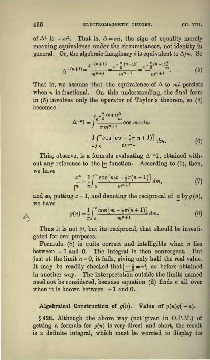
A /
436 ELECIROJIIAGNETIC THEORY. CII. VIII.
of A2 is - m2• That is, A=rni, the sign of equality merely meaning equivalence under the circumstances, not identity in general. Or, the algebraic imaginary i is equivalent to A/m. So
i-(n+l) - �(n+I)i _ �(n+l)� -ln+l)-
_€ 2 € 2 "' A - inn+l - nin+l mn+l • (5)
That is, we assume that the equivalence of A to mi persists when n is fractional. On this understanding, the final form in (5) involves only the operator of Taylor's theorem, so ( 4) becomes
_�(n+l)�
b.-"1 = !€ 2
m COS mx dm 1rmn+1
(6)
This, observe, is a formula evaluating A-"l, obtained without any reference to the � function. According to (1), then, we have
� = !J"' cos[mx -½1r(n + 1)] dm, (7)
\� 11" o rnn+l and so, putting x= 1, and denoting the reciprocal of� by g(n),we have
( )- lf"'cos [m-½1r(n+ 1)] d g n - _ ---=--���� m. 7r o mn+l (8)
Thus it is not �• but its reciprocal, that should be investigated for our purposes.
Formula (8) is quite correct and intelligible when n lies between -1 and 0. The integral is then convergent. But just at the limit n=O, it fails, giving only half the real value. It may be readily checked that l..=J = 1r½, as before obtained in another way. The interpretation outside the limits named need not be considered, because equation (2) finds n all over when it is known between -1 and O.
Algebraical Construction of g(n). Value of g(n)g( -n).
§426. Although the above way (not•given in O.P.M:.) ofgetting a formula for g(n) is very direct and short, the result is a definite integral, which must be worried to display its

GENERALISED DIFFERENTIATION AND DIVERGENT SERIES, 437
effective meaning. The curve of. g(n) can be drawn approximately at once by plotting its known values when n is integral, viz., 0 for every negative integer, and 1, 1, ½, ¼, -h, &c., at n-=O, 1, 2, 8, 4, &c. By the look of it, we see that the curve has a maximum between O and 1, and is oscillatory on the negative side, whilst continuously positive on the positive side. This is confirmed by plotting the midway values, also known, for n = ½, !, &c. The range of the oscillations is now approximntely indicated. As n increases negatively, the range increases.
O.P .M., §§ 17, 18, 19. If we turn right to left, we shallobtain the similar curve of g( -n), oscillatory on the right side of the origin, and continuously positive on the left side, with a maximum between O and -1.
The two curves are remarkably connected. Form the curve of the product g(n) g( - n). It is oscillatory on both sides. It has a zero for every integral value of n, positive and negative, and has the value 1 at the origin. This defines the function (sin mr)/nrr. That is,•
sin nrr g(n)g(-n)= -, (9) nrr
for all values of n. The values of g(½), &c., follow at once. Now (0) is the same as
g(n) g( -n) = (1-n2) (1-¼n2) (1 -½n2) •••• , (10) therefore, since the zeros of g(n) are known,
g(n)=X(l+n)(l+½n)(l+¼n) ..... , (11) g(-n)=X-1(1-n)(l-½n)(l-¼n) .... , (12)
where X is some function which does not introduce fresh zeros. Since n=O makes g(O)=X apparently in (11), it might be thought that X = 1. But it is co instead when· n is -, and O when n is+, as may be easily seen by drawing the curve
y=(l+n) (l+½n) ... (1+�) (13)
with a limited number of products. This is an oscillatory curve crossing then-axis at the points -1, - 2, &c., up to - r.
* There might be an extra factor. But there is not, to harmonise g(n) and g( - nj. Or we may regard the value of g( - ½) as known, to determinethe factor to be 1,

438 ELECTROMAGNETIC THEORY, OH. VIII,
Now as r is increased, the range of the oscillations gets smaller, and tends to become infinitely small when r= oo. This is confirmed by the fact that (13) is identically the same as
y=l+n+n(n+l)+ •• , +n(n+l)(n+2) ... (n+r-l),(l4)
� t viz., the first r + 1 terms in the expansion of (1 -1 )-" by the binomial theorem. When r is oo, y is zero for all negative and oo for all positive values of n.
The X multiplier must therefore be oo when n is negative. There is a radical distinction between the vanishing of y at n= -1, -2, &c., and the vanishing between these values. In the first case the zeros are absolute, and cannot be magnified. The curve crosses the axis at the points named. But the
· vanishing of y between can be cancelled by infinite magnification, so as to lift up the curve of y from the zero line tothe g(n) curve. Thus, choose X so that equation (11) shallbe true when there are r products and n is an integer. Thismakes
or
For example, if n is 10 and r is 100, then
X = 1 . 2 . 3 • 4 .• � • 99 . 100 _ 1 .1 . 2 . 3 . 4 .... 109 . 110 101 ..• 110 As 1· is indefinitely increased this becomes r-", so g(n) = r-"(1 +n)(l +½n) .... (1 +n/r)=r"(l -l)-11, (15)
The limit that is tended to when r is made infinite is the value of g(n).
By logarising (15) we get n2. ns n4 login= -nC+- S
2- -S
3+-S
4- ... , (lG)
L 2 3 4
1 1 where Sm= l+- +- + ... , 0 = 81
- log r= 0·5772. (17) 2"' 3m
From (16) may be derived a formula for g(n) in rising powers of n, namely
n2 nsg(n) = 1 +On+ (02 - S
2) -+ (03 -30S2 + 2S3)-2 �
+ (04 - 60.2S2 + 80S
3 + 3S2
2 - 6S4)� +. . . . (18)

GENERALISED DIFFERENTIATION AND DIVERGENT SERIES, 439
Like 1r, the value of Chas been calculated to a large number of places of decimals, though I do bot know that anything is gained by it. Something wonderful might however turn up, for instance, a long succession of O's.
The cosine function may similarly be split into two, making
f(n)f(-n)=cosmi, and (n-½)J(n)=/(n-1). (19)
But this f(n) is not useful like the g(n) function.
Generalisation of Exponential Function.
§ 427. Passing on to O.P.M., § 20, 21, the usual formuladefining t: and expressing Euler's Gamma integral is equivalent to
f"'e-"'x" 1= -dx, (20) 0 e.
provided n is over -1. There are two ways of developing the indefinite integral " by parts," say
( :i;n+l xn+2 xn+s ) W1
=e -x tn+ I +
/n+2 +
tn+3 + ... ' (21)
(xn xn -1 x7,-2 )- W2 = - e-X - + --1
+ 12 + .. • •
E /n- -2 (22)
So [w1] between any two limits is equal to [ - w2] between the same limits. That is, [w1 +w2] between any two limits, iszero. Therefore w1 + w2 does not change its value with :c. But does its value depend upon n? No, because if n is > - I, we may divide the integral (20) into two, one going from O to x, the other from x to CD. For the first use (21), since w1 = O when x = 0 ; and for the second use (22), since w2 = O when x= CD, We get
(23) or, which is the same,
xn-1 xn xn+l xn
eX = "· + \ n -1 + � + [n + I + ·" = � � • (24)
the series to be continued both ways. The assumption was that n> -1. But the change of n to n - I in (24) makes no

440 ELECTROMAGNETIC THEORY, CH. Yill.
difference. So (24) is true for all values of n. The series on, the right is a periodic function of n in appearance, since the
change of n to n + l reproduces the series. But as regardsthe value, the periodicity is only apparent. It is always e"'. Innumerical calculation only the initial. convergent part of theseries on its divergent side is to be counted, though all on theconvergent side, as usual. Note that x is a positive quantity all through. Whennegative another formula is needed, to be given later on.
The function w1 may be developed in a rising power seriesoperationally thus,W1 = t,_-1 .-xt,.-nJ = t,.-1(u + 1)--IIC" = u-1(t. + I)-"�
Li+ 1
=(Cl + 1)-(n+i) = t. -(n+I) - (n + l)u -(n+2)+(n+l�n + 2)u-<n+a>_ ... , (25)
expanding by the binomial theorem; and now a,lgebrising,we get xn+l xn+2 (n+ l)(n+2) xn+a W1 = fn+1-(n+l)ln+2 + � (n+s-···· (26)This may be confirmed by (21). But a similar operationaltreatment of w
2 fails. So expand w
2 in (22) in a power series
by direct multiplication, using the usual formula for c". Theresult is xn-1 x" x"+1 w
2=··· ,;,- (l-It-1 +-(l-l)"+- (I-ltt1+ ... -w1
• �-1 � iii+ 1 ---- (27).Butw
1+w
2= 1, so (1-1)" ,. 1=�---X.
� (28)
This is the result we shall get by developing (24) to apower series, multiplying it by the usual c" expansion. Amore general formula. including (28) will occur later. Theapparent numerical unintelligibility is no necessary bar to theuse of (28) as a working and transforming formula.. It oftenturns up. By (1 - 1 )" is to be understood the expansionaccording to the binomial theorem, in powers of the second l.