36C and 36D Gas Control Product Information5 36C and 36D GAS CONTROL PRODUCT INFORMATION R-3769C...
12
36C and 36D Gas Control Product Information The 36C and 36D combination gas control valves are compact multifunction controls designed to meet requirements for use with Standing Pilot systems and all types of intermittent ignition systems (Direct Spark, Hot Surface, Proven Pilot, and Cycle Pilot). Along with its compact size, all control adjustments and features, as well as the system interface wiring panel, have been designed on the top surface of the control for simplified application and easy accessibility. Information in this manual is provided to qualified HVAC Professionals Only for the installation and replacement of gas valves. Homeowners must contact their local HVAC Contractor for gas valve replacement. Any gas valve suspected of damage or if it has been flooded with water must be replaced immediately. There are no service- able parts on a gas valve.
Transcript of 36C and 36D Gas Control Product Information5 36C and 36D GAS CONTROL PRODUCT INFORMATION R-3769C...

36C and 36D Gas ControlProduct Information
The 36C and 36D combination gas control valves are compact multifunction controls designed to meet requirements for use with Standing Pilot systems and all types of intermittent ignition systems (Direct Spark, Hot Surface, Proven Pilot,
and Cycle Pilot). Along with its compact size, all control adjustments and features, as well as the system interface wiring panel, have been designed on the top surface of the control for simplified application and easy accessibility.
Information in this manual is provided to qualified HVAC Professionals Only for the installation and replacement of gas valves. Homeowners must contact their local HVAC Contractor for gas valve replacement.
Any gas valve suspected of damage or if it has been flooded with water must be replaced immediately. There are no service-able parts on a gas valve.

2
36C and 36D GAS CONTROLPRODUCT INFORMATION
R-3769C
General Specifications
Standard Features
Optional Features
❏ Pressure switch❏ Thermocouple operated safety valve❏ Negative pressure regulator❏ Natural to LP regulator selector (convertible)❏ Step opening-regulated (non-convertible)❏ 2 stage (Relay or Bi-metal operated)❏ Slow opening
❏ Inlet screen ❏ Automatic valves seal with in-line pressure❏ Ambient temperature (most models) -40˚ to 175˚F❏ Mounting - horizontal, vertical, and 90˚ from horizontal❏ Pilot filter❏ Manual shut-off valve❏ Top mounted components❏ Easily accessible pilot and outlet pressure tap❏ Easy grip pipe boss
CURRENT REQUIREMENTS
WITHOUT REDUNDANTSOLENOID
VOLTAGEFREQUENCY
24V, 60HZ
120V, 60HZ
240V, 60HZ
24V, 50HZ
120V, 50HZ
240V, 50HZ
WITH REDUNDANTSOLENOID
.190/.230 AMPS
.030/.042 AMPS
.016/.020 AMPS
.230/.270 AMPS
.030/.042 AMPS
.017/.021 AMPS
.550/.650 AMPS
.102/.138 AMPS
.054/.067 AMPS
.450/.550 AMPS
.100/.200 AMPS
.050/.070 AMPS
❏ Delay opening❏ Conduit connection❏ Inlet pressure tap❏ Right/left angle outlets❏ Solenoid operated redundant valve❏ Adjustable pilot pressure (non-regulated)❏ Mounting holes for 8-32 screws
36C/36D Schematic Gas Flow Diagram
ADJUSTMENT RANGE:Natural Gas: 2.5” to 5” W.C.LP Gas: 4.2” to 11.0” W.C. 7.5” to 12.0” W.C.
Regulator Information
Maximum Pressure: 1⁄2 PSIAgency Approved: -AGA all models -CGA all models -UL as required
MANUALVALVE
ECO
ECO TERMINALS TO POWER HEAD COIL(OPTIONAL)
PILOT FILTER
PILOT ADJSCREW
(LOCATEDAT TOP)
INLET
INTERRUPTERIN OPEN POSITION
TOPILOT OUTLET
WORKING GAS PRESSURE
DIAPHRAGMSPRING
DIAPHRAGM
OUTLET REGULATED MAIN GASFLOWING
MANUAL VALVEWINDOW OPEN
CONTROL ORIFICE
MAIN VALVE
CYCLINGVALVEOPEN
RELAYCOIL
BY PASSORIFICE
VENTADJUST SCREWMASTER
REGULATOROPEN
LINE INTERRUPTER GASVALVE FOR USE WITH THERMOCOUPLE
(STANDING PILOT)
PILOT FILTER
PILOT ADJSCREW
(LOCATEDAT TOP)
INLET
REDUNDANT/PILOT VALVEIN OPEN POSITION
TOPILOT OUTLET
WORKING GAS PRESSURE
DIAPHRAGMSPRING
DIAPHRAGM
OUTLET REGULATED MAIN GASFLOWING
MANUAL VALVEWINDOW OPEN
CONTROL ORIFICE
MAIN VALVE
CYCLINGVALVEOPEN
RELAYCOIL
BY PASSORIFICE
VENTADJUST SCREWMASTER
REGULATORCLOSED
AUTOMATIC GAS VALVE(INTERMITTANT IGNITION)
MANUAL VALVEIN "ON" POSITION
VALVELEVER

3
36C and 36D GAS CONTROLPRODUCT INFORMATIONR-3769C
0 100 200 300 500FLOW (1000 BTU/HR NAT. GAS)
OU
TLE
T P
RE
SS
UR
E (
IN. W
.C.)
14" MAX. INLET/2.5" W.C. OUTLET
14" MAX. INLET/5" W.C. OUTLET
21" W.C. INLET/2.5" W.C. OUTLET
21" W.C. INLET/5" W.C. OUTLET
5.5
5
4.5
4
3.5
3
2.5
2400
7" MIN. INLET/2.5" W.C. OUTLET
7" MIN. INLET/5" W.C. OUTLET
RANGE OF REGULATION(OUTLET PRESSURE VS. FLOW)
Performance Curves
Range of Regulation Capacity
1” PRESSURE DROP CAPACITY RATING
AGA STD. NAT. GAS(1,000 BTU/CU. FT.)
LP GAS(2,500 BTU/CU. FT.)
PIPE SIZES AVAILABLE
BTU/HR
1⁄2” X 3⁄8”1⁄2” X 1⁄2”1⁄2” X 3⁄4”3⁄4” X 3⁄4”
100,000230,000230,000280,000
162,000372,600372,600453,600
2
1.5
1
0.5
00 100 200 300 400
FLOW (1000 BTU/HR NAT. GAS)
1⁄2” X 1⁄2”1⁄2” X 3⁄8”
3⁄4” X 3⁄4”
DIF
FE
RE
NT
IAL
PR
ES
SU
RE
(IN
. W.C
.)
1” PRESSURE DROP CAPACITYDIFFERENTIAL PRESSURE VS. FLOW
1” Pressure Drop Capacity
RANGE OF REGULATION
AGA STD. NAT. GAS.64 SP. GR.
(1,000 BTU/CU. FT.)
LP GAS1.53 SP. GR.
(2,500 BTU/CU. FT.)PIPE SIZES AVAILABLE
1⁄2” X 3⁄8”1⁄2” X 1⁄2”1⁄2” X 3⁄4”3⁄4” X 3⁄4”
15,000 - 100,00030,000 - 290,00030,000 - 290,00050,000 - 400,000
15,000 - 162,00030,000 - 469,00030,000 - 469,00050,000 - 648,000

4
36C and 36D GAS CONTROLPRODUCT INFORMATION
R-3769C
Features and Options
Fast Open Control
Slow Open Control
Manual HI-LO Adjustable Control
This control has a fast opening characteristic which is suitable for a wide range of applications. It provides a fast rise to full pressure upon energizing the automatic valves. Regulator spring conversion kits are available for most models.
This control has slow opening characteristic. It provides a slow increase of gas to full pressure for smoother ignition, as may be required. The control can be a fast or slow close as well.
This control has a manual outlet pressure adjustment characteristic. It provides a fast rise of gas to the manually adjusted outlet pressure for a preferred flame setting in gas fireplace and gas log applications.
NOTE: TYPICAL OPENING CURVE NATURAL GAS 25,000 BTU/HR. 7” W.C. INLET/1.5” W.C. MINIMUM/3.5” W.C. MAXIMUM.
NOTE: TYPICAL OPENING CURVE NATURAL GAS 120,000 BTU/HR. 7” W.C. INLET / 3.5” W.C. OUTLET.
NOTE: TYPICAL OPENING CURVE NATURAL GAS 200,000 BTU/HR. 7” W.C. INLET / 3.5” W.C. OUTLET.
Negative Regulator Control
This control is designed for direct burner ignition applications with appliances having premix type burners using a combustion air blower requiring regulated negative outlet pressure. The control is equipped with dual automatic valves that control gas flow to the main burner, a two position manual valve for manual gas shut off, and a negative pressure regulator. A variety of models are available to suit voltage, pipe size and pressure regulator requirements.
NOTE: TYPICAL OPENING CURVE NATURAL GAS 200,000 BTU/HR. 7” W.C. INLET / -.2” W.C. AT -2 W.C. VACUUM PRESSURE.
36C/36D SLOW OPENING GAS VALVE4.0
3.5
3.0
2.5
2.0
1.5
1.0
0.5
0.00 4 6 8 12
SECONDSO
UT
LET
PR
ES
SU
RE
(IN
. W.C
.)
10
36C/36D FAST OPENING GAS VALVE4.0
3.5
3.0
2.5
2.0
1.5
1.0
0.5
0.00 2 4 6 8 10
SECONDS
OU
TLE
T P
RE
SS
UR
E (
IN. W
.C.)
36C/36D NEGATIVE REGULATOR0
0.05
-0.1
-0.15
-0.2
-0.250 2 4 6 8 10
SECONDS
OU
TLE
T P
RE
SS
UR
E (
IN. W
.C.)
36D MANUAL HI-LO ADJUSTABLE GAS VALVE4.0
3.5
3.0
2.5
2.0
1.5
1.0
0.5
0.00 2 4 6 8 10
SECONDS
OU
TLE
T P
RE
SS
UR
E (
IN. W
.C.)
(MINIMUM)
(MAXIMUM)
OFF
ON
PILOT
OFF
ON
PILOT
OFF
ON
PILOT
OFF
ON
PILOT
OFF
ON
PILOT
OFF
ON
PILOT

5
36C and 36D GAS CONTROLPRODUCT INFORMATIONR-3769C
Features and Options
This control has a step open feature that regulates the outlet to an initial step pressure (non-field adjustable) and rises to the full outlet pressure. It provides a step pressure for softer ignition.
Options:1. Regulated step factory set to a predetermined step pressure.2. Fixed orifice step internally orificed for a step pressure based upon inlet pressure and flow.
Step Open Control
Two Stage Control
This control has a two-stage feature. Upon energizing the main and redundant control valves, the servo regulator will provide a low fire rate until the high fire relay or bi-metal heater is energized or manual selection is made. (Adjustable high fire.)
Options:1. Bi-metal operated for a gradual change from the first stage to second stage.2. Relay operated for an instantaneous change from the first stage to the second stage.3. Manually operated from first to second stage with step at first stage when in second stage position.
Convertible Regulator
The convertible regulator option involves a construction which permits easy Natural to LP conversion (or vice versa) by removing, inverting and re-placing the regulator cap screw or by a mechanical adjustment. This feature easily lends itself to use in mobile homes and infra-red applications.
Options:1. Fixed orifice step internally orificed for a step pressure based upon inlet pressure.2. Fast open to full outlet pressure.
NOTE: TYPICAL OPENING CURVE NATURAL GAS 200,000 BTU/HR. 7” W.C. INLET / 1” W.C. FIRST STAGE/3.5”W.C. SECOND STAGE.
36C/36D STEP OPENING GAS VALVE4.0
3.5
3.0
2.5
2.0
1.5
1.0
0.5
0.00 2 4 6 8 10
SECONDS
OU
TLE
T P
RE
SS
UR
E (
IN. W
.C.)
NOTE: TYPICAL OPENING CURVE NATURAL GAS 200,000 BTU/HR. 7” W.C. INLET / 3.5” W.C. OUTLET/1” W.C. STEP.
36C/36D TWO STAGE GAS VALVE4.0
3.5
3.0
2.5
2.0
1.5
1.0
0.5
0.00 2 4 6 8 10
SECONDS
OU
TLE
T P
RE
SS
UR
E (
IN. W
.C.)
36C/36D NAT/LP CONVERTIBLE GAS VALVE4.0
3.5
3.0
2.5
2.0
1.5
1.0
0.5
0.00 2 4 6 8 10
SECONDS
OU
TLE
T P
RE
SS
UR
E (
IN. W
.C.)
NOTE: TYPICAL OPENING CURVE NATURAL GAS 200,000 BTU/HR. 7” W.C. INLET / 3.5” W.C. OUTLET.
OFF
ON
PILOT
OFF
ON
PILOT
OFF
ON
PILOT
OFF
ON
PILOT
OFF
ON
PILOT
LCO
OFF
ON
PILOT
OFF
ON
PILOT

6
36C and 36D GAS CONTROLPRODUCT INFORMATION
R-3769C
System Applications
HSI CONTROL. The thermostat calls for heat and energizes the HSI control. If the system is equipped with prepurge, the purge fan is energized and power will be delayed thirty seconds before application to the silicon carbide igniter. If prepurge is not selected, the igniter is powered within one second. The igniter heats up and at the end of the heating period, the redundant and main valves are opened. A flame must be detected within a fixed time period or both valves close, the igniter is turned off and the HSI control locks out unless the system is equipped with retry. Retry indicates the ignition sequence will be repeated for a total of three tries if flame is undetected or lost within 30 seconds of ignition.
Accessories: HSI Control, Sense Electrode, Silicon Carbide Igniter.
Hot Surface Ignition Systems
Direct Spark Ignition System
The thermostat calls for heat and simultaneously energizes the DSI control module and both redundant and main gas valves. Sparks at the ignition electrodes ignite the gas at the main burner. Flame is sensed through the electrodes by the flame detection circuit and shuts off the sparking. If flame is not established within a fixed time period (lock-out time) both valves close, sparking ceases and the control module locks out.
Accessories: DSI Control, Electrodes.
INTEGRATED CONTROL. The 50A50 integrated Hot Surface Ignition control employs a microprocessor to continuously monitor, analyze, and control the proper operation of the gas burner, inducer, and fan. Signals interpreted during continual surveillance of the thermostat and flame sensing element initiate automatic ignition of the burner, sensing of the flame, and system shut-off during normal operation. The control incorporates system fault analysis for quick gas flow shut-off, coupled with automatic ignition retry upon sensing a fault correction.
THERMOSTAT
HOT LINE VOLTAGE NEUTRAL
COMMON (“C”)W R
LINE VOLTAGE
LOW VOLTAGE
REDUNDANTVALVE
TRANSFORMER24 VOLTS A.C.
60 H.Z.
MAINVALVE
MV
MV
TR
TH
FP
GND
L
IGN
BLACK
SILICON CARBIDEIGNITOR
WH
ITE
BLA
CK
LIM
IT
FLAMESENSOR PROBE
HEAT COOL PARK PARK
CIRCULATORBLOWER
CIRCNEU IND
INDNEU
INDUCER
K1a K1b
K2 K4
RRO2
RO1
ROLLOUTSWITCH
THXFMRHOT
XFMRNEU
TRC
YGW
24 VAC
COMPRESSORCONTACTORCOIL
THERMOSTAT
R
YGW
HLI
AUX.LIMIT
HIGHLIMIT
PRESSURESWITCH
HLOPS
K8
K7
GASVALVE
MVMVGNDLIGNFP2FP1
IGNITOR
FLAMESENSEPROBE
LINE HOT
LINE NEU120 VAC
MAINVALVE
MV
MV
TR
TH
24V.
GND
REDUNDANTVALVE
SPARK RETURN
DSICONTROL
H.V
.
LEA
D

7
36C and 36D GAS CONTROLPRODUCT INFORMATIONR-3769C
System Applications
The thermostat calls for heat and simultaneously energizes the pilot valve and the Proven Pilot control. Sparking from the ignition electrode to the pilot burner ignites the gas at the pilot burner. Flame is sensed by the flame detection circuit which energizes the main valve. Main burner gas is ignited and sparking ceases once a pilot flame is detected.
Accessories: Proven Pilot Control, Pilot Burner Assembly.
Proven Pilot System
The thermostat calls for heat and simultaneously energizes pilot solenoid and pilot relight control. Pilot valve opens and relight begins sparking. Gas flow activates the pressure switch. Sparks ignite pilot gas. Once the flame is detected, the sparks stop. After sufficient heat is sensed by the Mercury Flame Sensor, the main valve is energized and the system is in operating mode. (Fig. 1)
The schematic for “ALL GASES,” Figure 2, includes a safety timer which acts to close the main gas valve, turns off the pilot redundant coil and locks out the system should a flame not be detected within a fixed period of time.
Accessories: Mercury Flame Sensor, Pilot Burner/Electrode Assembly, Pilot Relight Control, Safety Timer (for all gas systems).
Cycle Pilot System
Standing Pilot System
Gas flow to the pilot burner is controlled by a safety valve which is manually operated and held in by current generated from a thermocouple placed in the pilot flame. When the thermostat calls for heat the main valve is energized.
THERMOSTAT
LIMIT
HOT LINE VOLTAGE
120 VAC
NEUTRAL
COMMON (“C”)W R
25 VAC
H.V. LEAD
IGNITIONELECTRODE
(PILOT)
SENSEELECTRODE
PILOTVALVE
MAINVALVE
TH
PV
MV
MV
PV
TR
GND
FP
LINE VOLTAGE
LOW VOLTAGE
54
32
11
62
34
5
16
23
45
PILOT REDUNDANT
COIL
MAIN COIL
3098 SENSOR
HOT
COLD
PRESSURESWITCH
6 3 2 5 4
WIRING HARNESS
2
3
4
TO ELECTRODE
T2 T1
THRU MOUNTINGHOLES
THERMOSTATLIMIT
24 VAC
LINE
40VATRANSFORMER
NATURAL GASFigure 1
5059
ALL GASESFigure 2
PILOT REDUNDANT
COIL
MAIN COIL
3098 SENSOR
HOT
COLD
PRESSURESWITCH
WIRING HARNESS
2
3
4
TO ELECTRODE
T2 T1
THRU MOUNTINGHOLES
THERMOSTATLIMIT
24 VAC
LINE
5059
5 4 2 3 1
T1T2
6 3 2 5 4
WARP SWITCH HEATER
WARP SWITCH SAFETY
TIMER5022
BLU
E
RE
D
TAN
YE
L
OR
G
CYCLE PILOT HARNESSESHARNESSLENGTH
TYPE NO.
36”
36”
F115-0059
F115-0064
Thermocoupleconnection E.C.O.
Micro device
Leadassembly
E.C.O. Terminals
Wiring for Energy Cut-Off (E.C.O.) connection
HighLimit
PowerUnit
TH TH-PG PG
Thermostat
White-RodgersGas Valve
To PilotGenerator
Wiring for 36C03U/36C13U/36D34U (.750 Volt)
8
36C and 36D GAS CONTROLPRODUCT INFORMATION
R-3769C
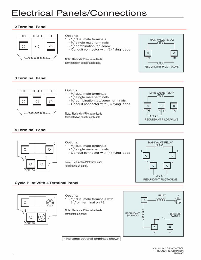
Electrical Panels/Connections
2 Terminal Panel
Options:* - 1⁄4” dual male terminals - 1⁄4” single male terminals - 1⁄4” combination tab/screw - Conduit connector with (2) flying leads
Cycle Pilot With 4 Terminal Panel
Options:* - 1⁄4” dual male terminals with 3⁄16” pin terminal on #2
4 Terminal Panel
Options:* - 1⁄4” dual male terminals - 1⁄4” single male terminals - Conduit connector with (4) flying leads
3 Terminal Panel
Options:* - 1⁄4” dual male terminals - 1⁄4” single male terminals - 1⁄4” combination tab/screw terminals - Conduit connector with (3) flying leads
Note: Redundant/Pilot valve leads terminated on panel if applicable.
Note: Redundant/Pilot valve leads terminated on panel.
Note: Redundant/Pilot valve leads terminated on panel.
Note: Redundant/Pilot valve leads terminated on panel if applicable.
* Indicates optional terminals shown
TH-TRTH TR
TH-TRTH TR
1 2
3 4
PILOT ADJ.
1 2
3 4
PILOT ADJ.
MAIN VALVE RELAY
TH TR
REDUNDANT PILOT/VALVE
MAIN VALVE RELAY
TH TR
REDUNDANT PILOT/VALVE
TH - TR
MAIN VALVE RELAY
1 2
REDUNDANT PILOT/VALVE
3 4
RELAY1 2
REDUNDANTSOLENOID
3 4
PRESSURESWITCH

9
36C and 36D GAS CONTROLPRODUCT INFORMATIONR-3769C
Electrical Panels/Connections
Cycle Pilot With Plug In Receptacle
Options: - Edge connector - Wiring harness with connector - Flying leads* - 1⁄4” male “Com, L, S” terminals - Plug in receptacle on top or outlet side
* Indicates optional terminals shown
Millivolt 3 Terminal Panel
Note: Second stage relay leads and redundant valve leads terminated on panel.
Relay 2 Stage
Options:* - 1⁄4” dual male terminals - Edge connector - Flying leads
PILOTADJ.
SL
CO
M.
Bi-metal 2 Stage
Options:* - (6) 1⁄4” male terminals - (5) 1⁄4” male terminals
Note: Redundant/Pilot valve leads terminated on panel.
D-1 D-2
C-1W-1
C-2
W-2
PILO
TA
DJ.
1 2
3 4
PILOT ADJ.
TH-PGTH PGOptions:* - 1⁄4” combination tab/screw terminals
BLACK PRESSURE
SWITCH
TAN TAN
REDUNDANTCOIL
WHITE
MAINRELAYCOIL
TAN
TAN
S
L
COMMON
4 2
3
REDUNDANT/PILOT VALVE
MAIN VALVE
D-2
W-1
W-2 C-2
C-1
HI-LO OPERATOR
D-1 REDUNDANT/PILOT VALVE
MAIN VALVEW-1
W-2 C-2
C-1
HI-LO OPERATOR
D-1
12
2
3
2ND STAGERELAY
MAIN VALVE
REDUNDANTVALVE
4
36D13
GREEN
RED
4
6 5 4 3 2 1
23
TAN
TAN
TAN
PRESSURESWITCH
RELAY COIL
( WITH PRESSURE SWITCHAND EDGE CONNECTOR )
MAIN VALVE RELAY
TH PGTH-PG

10
36C and 36D GAS CONTROLPRODUCT INFORMATION
R-3769C
Dimensions
Basic Model (24V or Millivolt)
Manual 2 Stage With Regulated Step
Regulated Step
Basic Model (120V or 240V)
Includes all basic 24V or 750 millivolt as well as negative regulator models.
Includes all 120V or 240V basic models with a conduit connector.
For all regulated step models including convertible models with a natural/LP gas selector feature.
For manual Hi-Lo two stage type models.

11
36C and 36D GAS CONTROLPRODUCT INFORMATIONR-3769C
Dimensions
Bi-metal Operated 2 Stage
Convertible Regulator (Natural/LP Selector)
Plug In Pilot Types
Relay Operated 2 Stage
Includes all relay operated 2 stage type models.
Includes all bi-metal operated 2 stage type models.
Includes all plug in pilot type pressure switch models.
Note: Gas valve shown has plug in pilot receptacle on top.
Includes all natural/LP gas convertible regulator models with the “Flip-Flop” type selector.

Models AvailableEach valve is uniquely defined by a model number succeeded by the type number as follows:
36C xx x TYPE xxBasic Model Number Series
Specification of options/features(numbered versions)
PACK OPTIONPACKCODE
BULK PACK20/BOX
SINGLE PACK1/BOX
PALLET PACK
* INCLUDES INDIVIDUAL INSTRUCTION SHEETS
B1
P1
S1*
VOLTAGE LETTER CODINGLETTER VOLTAGE FREQUENCY CURRENTNONE
ABCGHU
1XX2XX3XX4XX
1⁄2” x 3⁄8”1⁄2” x 1⁄2”1⁄2” x 3⁄4”3⁄4” x 3⁄4”
2412011524240240.750
A.C.A.C.A.C.A.C.A.C.A.C.D.C.
606050506050--
TYPE NUMBER NUMBER PIPE SIZE (INLET x OUTLET)
AccessoriesREGULATOR
CONVERSION KITS AVAILABLEF92-0656F92-0659F92-0737F92-0866F69-0727
F92-0514
LP to NAT GAS (2.5”-5.0”)NAT to LP GAS (7.5”-12.0”)NAT to LP GAS (Non-regulated)NAT to LP GAS (4.2”-11.0”)1⁄4” brass compression fittingfor pilot line conversionsOne 3⁄4” x 1⁄2” N.P.T. and one1⁄2” x 3⁄8” N.P.T. reducer bushings
36C01 NAT YES NO NO RELAY NO LINE INTERRUPTER, RELAY OPERATOR, REGULATOR36C02 NAT/LP YES YES NO RELAY NAT/LP FLIP-FLOP SELECTOR36C03 NAT YES YES NO RELAY STANDARD STANDING PILOT36C04 NAT YES YES REGULATED RELAY REGULATED STEP OPENING36C05 NAT YES YES REGULATED RELAY MANUAL HI-LO (TWO STAGE), NATURAL GAS36C10 ALL NO YES NO RELAY 36C03 WITH OUT REGULATOR36C12 NAT/LP YES YES REGULATED RELAY NAT/LP SELECTOR, REGULATED STEP OPENING W/NAT/LP SELECTOR36C13 LP YES YES NO RELAY 36C03 ONLY LP GAS36C14 LP YES YES REGULATED RELAY 36C04 ONLY LP GAS36C15 LP YES YES REGULATED RELAY MANUAL HI-LO (TWO STAGE), LP GAS36C21 ALL NO NO NO RELAY NO MANUAL VALVE, NO PILOT36C27 NAT YES NO REGULATED RELAY 36CO4 WITH OUT LINE INTERRUPTER36C36 NAT/LP YES NO NO RELAY PLUG-IN-PILOT36C38 NAT YES NO NO RELAY BI-METAL 2 STAGE36C40 NAT YES YES NO RELAY BI-METAL 2 STAGE36C41 LP YES YES NO RELAY BI-METAL 2 STAGE36C53 NAT.LP YES YES NO RELAY SLOW OPENING36C67 NAT/LP YES YES FIXED RELAY NAT/LP SELECTOR (”FLIP-FLOP“), STEP OPENING36C68 NAT/LP YES SOLENOID NO RELAY 36C03/C13 WITH REDUNDANT36C74 NAT/LP YES SOLENOID REGULATED RELAY 36C04/C14 WITH REDUNDANT36C76 NAT/LP YES SOLENOID NO RELAY BI-METAL 2 STAGE36C77 NAT/LP YES SOLENOID FIXED RELAY NAT/LP SELECTOR (”FLIP-FLOP“), STEP OPENING36C78 NAT/LP YES SOLENOID NO RELAY 36C77 WITH OUT STEP OPENING36C81 NAT/LP YES SOLENOID NO RELAY 36C53 WITH REDUNDANT, SLOW OPENING36C84 NAT/LP YES SOLENOID NO RELAY PRESSURE SWITCH, PLUG IN PILOT36C87 NAT/LP YES SOLENOID REGULATED RELAY PRESSURE SWITCH36C90 NAT/LP YES SOLENOID NO RELAY 36C68 LESS MANUAL VALVE36C92 NAT/LP YES SOLENOID NO RELAY 36C76 WITH PRESSURE SWITCH36C94 NAT/LP YES SOLENOID SLOW RELAY SLOW OPEN, PRESSURE SWITCH WITH PLUG IN PILOT36D01 NAT/LP YES NO FIXED RELAY 36C67 WITH OUT LINE INTERRUPTER36D11 ALL NO SOLENOID NO RELAY 36C90 WITH OUT REGULATOR36D13 NAT/LP YES SOLENOID NO RELAY RELAY OPERATED 2 STAGE36D14 NAT/LP YES SOLENOID NO RELAY 36D13 WITH PRESSURE SWITCH36D22 NAT YES YES NO RELAY 36C03 WITH BRITISH THREADS36D23 NAT/LP YES SOLENOID NO RELAY 36D13 WITH OUT MANUAL VALVE36D24 NAT/LP YES SOLENOID NO RELAY NEGATIVE REGULATOR WITH DELAYED OPENING36D27 NAT/LP YES SOLENOID NO RELAY NEGATIVE REGULATOR36D29 NAT/LP YES SOLENOID NO RELAY 36C76 WITH OUT MANUAL VALVE36D32 NAT/LP YES YES NO RELAY MANUAL HI-LO ADJUSTMENT
LINE MODEL NO. TYPE GAS REGULATOR INTERRUPTER STEP OPERATOR SPECIAL FEATURES*
*Models numbers may not be current production. Please consult White-Rodgers distributor or visit www.white-rodgers.com.
White-Rodgers is a division of Emerson Electric Co.
The Emerson logo is a trademark and service mark of Emerson Electric Co.
R-3769C1006
www.white-rodgers.comwww.emersonclimate.com